

Page 1

Wired Configuration Guide
Product Model : DWS-3000 Series
Unified Wired & Wireless Access System
Release 2.1
April 2008
©Copyright 2008. All rights reserved.
Page 2

Wired Configuration Guide
2 © 2001- 2008 D-Link Corporation. All Rights Reserved.
Page 3

Table of Contents
List of Figures. . . . . . . . . . . . . . . . . . . . . . . . . . . . . . . . . . . . . . . . . . . 9
List of Tables . . . . . . . . . . . . . . . . . . . . . . . . . . . . . . . . . . . . . . . . . . 13
About This Book . . . . . . . . . . . . . . . . . . . . . . . . . . . . . . . . . . . . . . . 15
Document Organization . . . . . . . . . . . . . . . . . . . . . . . . . . . . . . . . . . . . . . . 15
CLI/Web Examples - Slot/Port Designations . . . . . . . . . . . . . . . . . . . . . . . 16
Audience . . . . . . . . . . . . . . . . . . . . . . . . . . . . . . . . . . . . . . . . . . . . . . . . . . . 16
CLI Documentation. . . . . . . . . . . . . . . . . . . . . . . . . . . . . . . . . . . . . . . . . . . 16
1 Getting Started . . . . . . . . . . . . . . . . . . . . . . . . . . . . . . . . . . . . . . 17
In-Band and Out-of-Band Connectivity . . . . . . . . . . . . . . . . . . . . . . . . . . . 17
Configuring for In-Band Connectivity . . . . . . . . . . . . . . . . . . . . . . . . . . . . . . 17
Configuring for Out-of-Band Connectivity . . . . . . . . . . . . . . . . . . . . . . . . . . . 19
Starting the Switch . . . . . . . . . . . . . . . . . . . . . . . . . . . . . . . . . . . . . . . . . . . 20
Initial Configuration. . . . . . . . . . . . . . . . . . . . . . . . . . . . . . . . . . . . . . . . . . 20
Unified Switch Installation . . . . . . . . . . . . . . . . . . . . . . . . . . . . . . . . . . . . . 21
Quick Starting the Networking Device . . . . . . . . . . . . . . . . . . . . . . . . . . . . . . 21
System Information and System Setup. . . . . . . . . . . . . . . . . . . . . . . . . . . . . . . 21
2 Using the Web Interface. . . . . . . . . . . . . . . . . . . . . . . . . . . . . . . 27
Configuring for Web Access . . . . . . . . . . . . . . . . . . . . . . . . . . . . . . . . . . . . 27
Starting the Web Interface. . . . . . . . . . . . . . . . . . . . . . . . . . . . . . . . . . . . . . 28
Web Page Layout. . . . . . . . . . . . . . . . . . . . . . . . . . . . . . . . . . . . . . . . . . . . . . . 28
Configuring an SNMP V3 User Profile. . . . . . . . . . . . . . . . . . . . . . . . . . . . . . 29
Command Buttons . . . . . . . . . . . . . . . . . . . . . . . . . . . . . . . . . . . . . . . . . . . . . . 30
3 Virtual LANs. . . . . . . . . . . . . . . . . . . . . . . . . . . . . . . . . . . . . . . . 31
VLAN Configuration Example . . . . . . . . . . . . . . . . . . . . . . . . . . . . . . . . . . 32
Configuring a Guest VLAN. . . . . . . . . . . . . . . . . . . . . . . . . . . . . . . . . . . . . . . 32
Configuring Dynamic VLAN Assignments . . . . . . . . . . . . . . . . . . . . . . . . . . . 32
CLI Examples . . . . . . . . . . . . . . . . . . . . . . . . . . . . . . . . . . . . . . . . . . . . . . . 33
Example #1: Create Two VLANs. . . . . . . . . . . . . . . . . . . . . . . . . . . . . . . . . . . 33
Example #2: Assign Ports to VLAN2 . . . . . . . . . . . . . . . . . . . . . . . . . . . . . . . 33
Example #3: Assign Ports to VLAN3 . . . . . . . . . . . . . . . . . . . . . . . . . . . . . . . 33
Example #4: Assign VLAN3 as the Default VLAN . . . . . . . . . . . . . . . . . . . . . 34
Example #5: Assign IP Addresses to VLAN 2. . . . . . . . . . . . . . . . . . . . . . . . . 34
Web Interface . . . . . . . . . . . . . . . . . . . . . . . . . . . . . . . . . . . . . . . . . . . . . . . 34
Private Edge VLANs. . . . . . . . . . . . . . . . . . . . . . . . . . . . . . . . . . . . . . . . . . 35
CLI Example . . . . . . . . . . . . . . . . . . . . . . . . . . . . . . . . . . . . . . . . . . . . . . . . . . 36
4 802.1X Network Access Control . . . . . . . . . . . . . . . . . . . . . . . . 37
802.1x Network Access Control Example. . . . . . . . . . . . . . . . . . . . . . . . . . 38
3
Page 4

Wired Configuration Guide
Guest VLAN . . . . . . . . . . . . . . . . . . . . . . . . . . . . . . . . . . . . . . . . . . . . . . . . 39
Configuring Dynamic VLAN Assignment. . . . . . . . . . . . . . . . . . . . . . . . . . 41
5 Storm Control. . . . . . . . . . . . . . . . . . . . . . . . . . . . . . . . . . . . . . . .43
CLI Example. . . . . . . . . . . . . . . . . . . . . . . . . . . . . . . . . . . . . . . . . . . . . . . . 43
Web Interface . . . . . . . . . . . . . . . . . . . . . . . . . . . . . . . . . . . . . . . . . . . . . . . 45
6 Trunking (Link Aggregation) . . . . . . . . . . . . . . . . . . . . . . . . . . .47
CLI Example . . . . . . . . . . . . . . . . . . . . . . . . . . . . . . . . . . . . . . . . . . . . . . . . 47
Web Interface Configuration - LAGs/Port-channels . . . . . . . . . . . . . . . . . 50
Configuring the Guest VLAN by Using the CLI. . . . . . . . . . . . . . . . . . . . . . . . 39
Configuring the Guest VLAN by Using the Web Interface. . . . . . . . . . . . . . . . 40
Example #1: Set Broadcast Storm Control for All Interfaces . . . . . . . . . . . . . 43
Example #2: Set Multicast Storm Control for All Interfaces. . . . . . . . . . . . . . 44
Example #3: Set Unicast Storm Control for All Interfaces . . . . . . . . . . . . . . . 44
Example 1: Create two port-channels: . . . . . . . . . . . . . . . . . . . . . . . . . . . . . . 48
Example 2: Add the physical ports to the port-channels: . . . . . . . . . . . . . . . . 49
Example 3: Enable both port-channels.. . . . . . . . . . . . . . . . . . . . . . . . . . . . . . 49
7 IGMP Snooping . . . . . . . . . . . . . . . . . . . . . . . . . . . . . . . . . . . . . .51
Overview. . . . . . . . . . . . . . . . . . . . . . . . . . . . . . . . . . . . . . . . . . . . . . . . . . . 51
CLI Examples . . . . . . . . . . . . . . . . . . . . . . . . . . . . . . . . . . . . . . . . . . . . . . . 51
Example #1: show igmpsnooping . . . . . . . . . . . . . . . . . . . . . . . . . . . . . . . . . . 51
Example #2: show mac-address-table igmpsnooping . . . . . . . . . . . . . . . . . . . 52
Example #3: set igmp (Global Config Mode) . . . . . . . . . . . . . . . . . . . . . . . . . 52
Example #4: set igmp (Interface Config Mode). . . . . . . . . . . . . . . . . . . . . . . . 52
Web Examples. . . . . . . . . . . . . . . . . . . . . . . . . . . . . . . . . . . . . . . . . . . . . . . 53
8 Port Mirroring . . . . . . . . . . . . . . . . . . . . . . . . . . . . . . . . . . . . . . .59
Overview. . . . . . . . . . . . . . . . . . . . . . . . . . . . . . . . . . . . . . . . . . . . . . . . . . . 59
CLI Examples . . . . . . . . . . . . . . . . . . . . . . . . . . . . . . . . . . . . . . . . . . . . . . . 59
Example #1: Set up a Port Mirroring Session. . . . . . . . . . . . . . . . . . . . . . . . . 59
Example #2: Show the Port Mirroring Session . . . . . . . . . . . . . . . . . . . . . . . . 60
Example #3: Show the Status of All Ports . . . . . . . . . . . . . . . . . . . . . . . . . . . . 60
Example #4: Show the Status of the Source and Destination Ports. . . . . . . . . 60
Web Examples. . . . . . . . . . . . . . . . . . . . . . . . . . . . . . . . . . . . . . . . . . . . . . . 61
9 Port Security. . . . . . . . . . . . . . . . . . . . . . . . . . . . . . . . . . . . . . . . .63
Overview. . . . . . . . . . . . . . . . . . . . . . . . . . . . . . . . . . . . . . . . . . . . . . . . . . . 63
Operation . . . . . . . . . . . . . . . . . . . . . . . . . . . . . . . . . . . . . . . . . . . . . . . . . . 63
CLI Examples . . . . . . . . . . . . . . . . . . . . . . . . . . . . . . . . . . . . . . . . . . . . . . . 64
Example #1: show port security. . . . . . . . . . . . . . . . . . . . . . . . . . . . . . . . . . . . 64
Example #2: show port security on a specific interface . . . . . . . . . . . . . . . . . 64
Example #3: (Config) port security . . . . . . . . . . . . . . . . . . . . . . . . . . . . . . . . . 64
Web Examples. . . . . . . . . . . . . . . . . . . . . . . . . . . . . . . . . . . . . . . . . . . . . . . 65
4 © 2001- 2008 D-Link Corporation. All Rights Reserved.
Page 5

10 Link Layer Discovery Protocol . . . . . . . . . . . . . . . . . . . . . . . . . 69
CLI Examples . . . . . . . . . . . . . . . . . . . . . . . . . . . . . . . . . . . . . . . . . . . . . . . 69
Example #1: Set Global LLDP Parameters . . . . . . . . . . . . . . . . . . . . . . . . . . 69
Example #2: Set Interface LLDP Parameters. . . . . . . . . . . . . . . . . . . . . . . . . 70
Example #3: Show Global LLDP Parameters . . . . . . . . . . . . . . . . . . . . . . . . 70
Example #4 Show Interface LLDP Parameters . . . . . . . . . . . . . . . . . . . . . . . 70
Using the Web Interface to Configure LLDP . . . . . . . . . . . . . . . . . . . . . . . 71
11 Denial of Service Attack Protection . . . . . . . . . . . . . . . . . . . . . 75
Overview. . . . . . . . . . . . . . . . . . . . . . . . . . . . . . . . . . . . . . . . . . . . . . . . . . . 75
CLI Examples . . . . . . . . . . . . . . . . . . . . . . . . . . . . . . . . . . . . . . . . . . . . . . . 75
Web Interface . . . . . . . . . . . . . . . . . . . . . . . . . . . . . . . . . . . . . . . . . . . . . . . 76
12 Port Routing . . . . . . . . . . . . . . . . . . . . . . . . . . . . . . . . . . . . . . . . 77
Port Routing Configuration . . . . . . . . . . . . . . . . . . . . . . . . . . . . . . . . . . . . 77
CLI Examples . . . . . . . . . . . . . . . . . . . . . . . . . . . . . . . . . . . . . . . . . . . . . . . 78
Example 1. Enabling routing for the Switch . . . . . . . . . . . . . . . . . . . . . . . . . . 78
Example 2. Enabling Routing for Ports on the Switch . . . . . . . . . . . . . . . . . . 79
Using the Web Interface to Configure Routing. . . . . . . . . . . . . . . . . . . . . . 80
13 VLAN Routing . . . . . . . . . . . . . . . . . . . . . . . . . . . . . . . . . . . . . . 81
VLAN Routing Configuration . . . . . . . . . . . . . . . . . . . . . . . . . . . . . . . . . . . 81
CLI Examples . . . . . . . . . . . . . . . . . . . . . . . . . . . . . . . . . . . . . . . . . . . . . . . 81
Example 1: Create Two VLANs. . . . . . . . . . . . . . . . . . . . . . . . . . . . . . . . . . . . 82
Example 2: Set Up VLAN Routing for the VLANs and the Switch.. . . . . . . . . 83
Using the Web Interface to Configure VLAN Routing . . . . . . . . . . . . . . . . 84
14 Virtual Router Redundancy Protocol. . . . . . . . . . . . . . . . . . . . 87
CLI Examples . . . . . . . . . . . . . . . . . . . . . . . . . . . . . . . . . . . . . . . . . . . . . . . 87
Example 1: Configuring VRRP on the Switch as a Master Router. . . . . . . . . 88
Example 2: Configuring VRRP on the Switch as a Backup Router . . . . . . . . 89
Using the Web Interface to Configure VRRP . . . . . . . . . . . . . . . . . . . . . . . 90
15 Proxy Address Resolution Protocol (ARP). . . . . . . . . . . . . . . . 93
Overview. . . . . . . . . . . . . . . . . . . . . . . . . . . . . . . . . . . . . . . . . . . . . . . . . . . 93
CLI Examples . . . . . . . . . . . . . . . . . . . . . . . . . . . . . . . . . . . . . . . . . . . . . . . 93
Example #1 show ip interface. . . . . . . . . . . . . . . . . . . . . . . . . . . . . . . . . . . . . 93
Example #2: ip proxy-arp . . . . . . . . . . . . . . . . . . . . . . . . . . . . . . . . . . . . . . . . 94
Web Example. . . . . . . . . . . . . . . . . . . . . . . . . . . . . . . . . . . . . . . . . . . . . . . . 94
16 Access Control Lists (ACLs) . . . . . . . . . . . . . . . . . . . . . . . . . . . 95
Overview. . . . . . . . . . . . . . . . . . . . . . . . . . . . . . . . . . . . . . . . . . . . . . . . . . . 95
Limitations. . . . . . . . . . . . . . . . . . . . . . . . . . . . . . . . . . . . . . . . . . . . . . . . . . . . 95
MAC ACLs . . . . . . . . . . . . . . . . . . . . . . . . . . . . . . . . . . . . . . . . . . . . . . . . . 96
IP ACLs. . . . . . . . . . . . . . . . . . . . . . . . . . . . . . . . . . . . . . . . . . . . . . . . . . . . 96
ACL Configuration Process . . . . . . . . . . . . . . . . . . . . . . . . . . . . . . . . . . . . 97
5
Page 6

Wired Configuration Guide
IP ACL CLI Example . . . . . . . . . . . . . . . . . . . . . . . . . . . . . . . . . . . . . . . . . 97
MAC ACL CLI Examples . . . . . . . . . . . . . . . . . . . . . . . . . . . . . . . . . . . . . . 98
Web Examples. . . . . . . . . . . . . . . . . . . . . . . . . . . . . . . . . . . . . . . . . . . . . . 102
17 Class of Service Queuing. . . . . . . . . . . . . . . . . . . . . . . . . . . . . .109
Ingress Port Configuration. . . . . . . . . . . . . . . . . . . . . . . . . . . . . . . . . . . . 109
Egress Port Configuration - Traffic Shaping . . . . . . . . . . . . . . . . . . . . . . 110
Queue Configuration . . . . . . . . . . . . . . . . . . . . . . . . . . . . . . . . . . . . . . . . 110
Queue Management Type . . . . . . . . . . . . . . . . . . . . . . . . . . . . . . . . . . . . . 110
CLI Examples . . . . . . . . . . . . . . . . . . . . . . . . . . . . . . . . . . . . . . . . . . . . . . 110
Web Examples. . . . . . . . . . . . . . . . . . . . . . . . . . . . . . . . . . . . . . . . . . . . . . 113
Example #1: Create ACL 179 and Define an ACL Rule . . . . . . . . . . . . . . . . . 98
Example #2: Define the Second Rule for ACL 179 . . . . . . . . . . . . . . . . . . . . . 98
Example #3: Apply the rule to Inbound Traffic on Port 0/2 . . . . . . . . . . . . . . 98
Example #4: Set up a MAC Access List. . . . . . . . . . . . . . . . . . . . . . . . . . . . . . 98
Example #5: Specify MAC ACL Attributes . . . . . . . . . . . . . . . . . . . . . . . . . . . 99
Example #6 Configure MAC Access Group. . . . . . . . . . . . . . . . . . . . . . . . . . 100
Example #7 Set up an ACL with Permit Action. . . . . . . . . . . . . . . . . . . . . . . 101
Example #8: Show MAC Access Lists . . . . . . . . . . . . . . . . . . . . . . . . . . . . . . 101
MAC ACL Web Pages . . . . . . . . . . . . . . . . . . . . . . . . . . . . . . . . . . . . . . . . . . 102
IP ACL Web Pages. . . . . . . . . . . . . . . . . . . . . . . . . . . . . . . . . . . . . . . . . . . . . 105
Trusted and Untrusted Ports/CoS Mapping Table. . . . . . . . . . . . . . . . . . . . . 109
CoS Mapping Table for Trusted Ports. . . . . . . . . . . . . . . . . . . . . . . . . . . . . . 110
18 Differentiated Services . . . . . . . . . . . . . . . . . . . . . . . . . . . . . . .117
CLI Example . . . . . . . . . . . . . . . . . . . . . . . . . . . . . . . . . . . . . . . . . . . . . . . 118
DiffServ Inbound Configuration . . . . . . . . . . . . . . . . . . . . . . . . . . . . . . . . . . 118
Adding Color-Aware Policing Attribute. . . . . . . . . . . . . . . . . . . . . . . . . . . . . 120
Using the Web Interface to Configure Diffserv. . . . . . . . . . . . . . . . . . . . . 121
Configuring the Color-Aware Attribute by Using the Web . . . . . . . . . . . . . . 129
DiffServ for VoIP Configuration Example . . . . . . . . . . . . . . . . . . . . . . . . 131
Configuring DiffServ VoIP Support Example . . . . . . . . . . . . . . . . . . . . . . . . 132
19 RADIUS . . . . . . . . . . . . . . . . . . . . . . . . . . . . . . . . . . . . . . . . . . .133
RADIUS Configuration Example . . . . . . . . . . . . . . . . . . . . . . . . . . . . . . . 133
Configuring RADIUS by Using CLI Commands. . . . . . . . . . . . . . . . . . . . . . 134
Configuring RADIUS by Using the Web Interface. . . . . . . . . . . . . . . . . . . . . 135
20 TACACS+. . . . . . . . . . . . . . . . . . . . . . . . . . . . . . . . . . . . . . . . . .139
TACACS+ Configuration Example. . . . . . . . . . . . . . . . . . . . . . . . . . . . . . 139
Configuring TACACS+ by Using CLI Commands. . . . . . . . . . . . . . . . . . . . . 140
Configuring TACACS+ by Using the Web Interface . . . . . . . . . . . . . . . . . . . 141
21 DHCP Filtering . . . . . . . . . . . . . . . . . . . . . . . . . . . . . . . . . . . . .145
Overview. . . . . . . . . . . . . . . . . . . . . . . . . . . . . . . . . . . . . . . . . . . . . . . . . . 145
Limitations . . . . . . . . . . . . . . . . . . . . . . . . . . . . . . . . . . . . . . . . . . . . . . . . 145
CLI Examples . . . . . . . . . . . . . . . . . . . . . . . . . . . . . . . . . . . . . . . . . . . . . . 146
6 © 2001- 2008 D-Link Corporation. All Rights Reserved.
Page 7

Example #1: Enable DHCP Filtering for the Switch . . . . . . . . . . . . . . . . . . 146
Example #2: Enable DHCP Filtering for an Interface. . . . . . . . . . . . . . . . . 146
Example #3: Show DHCP Filtering Configuration . . . . . . . . . . . . . . . . . . . 146
Web Examples. . . . . . . . . . . . . . . . . . . . . . . . . . . . . . . . . . . . . . . . . . . . . . 146
22 Traceroute . . . . . . . . . . . . . . . . . . . . . . . . . . . . . . . . . . . . . . . . . 149
CLI Example . . . . . . . . . . . . . . . . . . . . . . . . . . . . . . . . . . . . . . . . . . . . . . . 149
23 Configuration Scripting. . . . . . . . . . . . . . . . . . . . . . . . . . . . . . 151
Overview. . . . . . . . . . . . . . . . . . . . . . . . . . . . . . . . . . . . . . . . . . . . . . . . . . 151
Considerations . . . . . . . . . . . . . . . . . . . . . . . . . . . . . . . . . . . . . . . . . . . . . 151
CLI Examples . . . . . . . . . . . . . . . . . . . . . . . . . . . . . . . . . . . . . . . . . . . . . . 151
Example #1: script. . . . . . . . . . . . . . . . . . . . . . . . . . . . . . . . . . . . . . . . . . . . . 151
Example #2: script list and script delete. . . . . . . . . . . . . . . . . . . . . . . . . . . . 152
Example #3: script apply running-config.scr . . . . . . . . . . . . . . . . . . . . . . . . 152
Example #4: show running-config . . . . . . . . . . . . . . . . . . . . . . . . . . . . . . . . 152
Example #5: copy nvram: script. . . . . . . . . . . . . . . . . . . . . . . . . . . . . . . . . . 153
Example #6: script validate running-config.scr . . . . . . . . . . . . . . . . . . . . . . 153
Example #7: Validate another Configuration Script. . . . . . . . . . . . . . . . . . . 154
24 Outbound Telnet. . . . . . . . . . . . . . . . . . . . . . . . . . . . . . . . . . . . 155
Overview. . . . . . . . . . . . . . . . . . . . . . . . . . . . . . . . . . . . . . . . . . . . . . . . . . 155
CLI Examples . . . . . . . . . . . . . . . . . . . . . . . . . . . . . . . . . . . . . . . . . . . . . . 155
Example #1: show network . . . . . . . . . . . . . . . . . . . . . . . . . . . . . . . . . . . . . . 156
Example #2: show telnet . . . . . . . . . . . . . . . . . . . . . . . . . . . . . . . . . . . . . . . . 156
Example #3: transport output telnet . . . . . . . . . . . . . . . . . . . . . . . . . . . . . . . 156
Example #4: session-limit and session-timeout. . . . . . . . . . . . . . . . . . . . . . . 156
Web Example. . . . . . . . . . . . . . . . . . . . . . . . . . . . . . . . . . . . . . . . . . . . . . . 157
25 Pre-Login Banner. . . . . . . . . . . . . . . . . . . . . . . . . . . . . . . . . . . 159
Overview. . . . . . . . . . . . . . . . . . . . . . . . . . . . . . . . . . . . . . . . . . . . . . . . . . 159
CLI Example . . . . . . . . . . . . . . . . . . . . . . . . . . . . . . . . . . . . . . . . . . . . . . . 159
26 Simple Network Time Protocol (SNTP) . . . . . . . . . . . . . . . . . 161
Overview. . . . . . . . . . . . . . . . . . . . . . . . . . . . . . . . . . . . . . . . . . . . . . . . . . 161
CLI Examples . . . . . . . . . . . . . . . . . . . . . . . . . . . . . . . . . . . . . . . . . . . . . . 161
Example #1: show sntp . . . . . . . . . . . . . . . . . . . . . . . . . . . . . . . . . . . . . . . . . 161
Example #2: show sntp client . . . . . . . . . . . . . . . . . . . . . . . . . . . . . . . . . . . . 161
Example #3: show sntp server. . . . . . . . . . . . . . . . . . . . . . . . . . . . . . . . . . . . 162
Example #4: configure sntp. . . . . . . . . . . . . . . . . . . . . . . . . . . . . . . . . . . . . . 162
Example #5: configure sntp client mode. . . . . . . . . . . . . . . . . . . . . . . . . . . . 162
Example #6: configuring sntp server . . . . . . . . . . . . . . . . . . . . . . . . . . . . . . 163
Example #7: configure sntp client port. . . . . . . . . . . . . . . . . . . . . . . . . . . . . 163
Web Interface Examples . . . . . . . . . . . . . . . . . . . . . . . . . . . . . . . . . . . . . . 163
27 Syslog . . . . . . . . . . . . . . . . . . . . . . . . . . . . . . . . . . . . . . . . . . . . . 167
Overview. . . . . . . . . . . . . . . . . . . . . . . . . . . . . . . . . . . . . . . . . . . . . . . . . . 167
7
Page 8

Wired Configuration Guide
CLI Examples . . . . . . . . . . . . . . . . . . . . . . . . . . . . . . . . . . . . . . . . . . . . . . 168
Web Examples. . . . . . . . . . . . . . . . . . . . . . . . . . . . . . . . . . . . . . . . . . . . . . 171
28 Port Description. . . . . . . . . . . . . . . . . . . . . . . . . . . . . . . . . . . . .173
CLI Example . . . . . . . . . . . . . . . . . . . . . . . . . . . . . . . . . . . . . . . . . . . . . . . 173
Configuring Port Description with the Web Interface . . . . . . . . . . . . . . . 174
Interpreting Log Files . . . . . . . . . . . . . . . . . . . . . . . . . . . . . . . . . . . . . . . . . . 167
Example #1: show logging. . . . . . . . . . . . . . . . . . . . . . . . . . . . . . . . . . . . . . . 168
Example #2: show logging buffered. . . . . . . . . . . . . . . . . . . . . . . . . . . . . . . . 168
Example #3: show logging traplogs . . . . . . . . . . . . . . . . . . . . . . . . . . . . . . . 169
Example 4: show logging hosts . . . . . . . . . . . . . . . . . . . . . . . . . . . . . . . . . . . 169
Example #5: logging port configuration . . . . . . . . . . . . . . . . . . . . . . . . . . . . 170
Example #1: Enter a Description for a Port . . . . . . . . . . . . . . . . . . . . . . . . . 173
Example #2: Show the Port Description . . . . . . . . . . . . . . . . . . . . . . . . . . . . 173
8 © 2001- 2008 D-Link Corporation. All Rights Reserved.
Page 9

List of Figures
Figure 1. Web Interface Panel-Example .............................................................. 28
Figure 2. Web Interface Panel-Example .............................................................. 29
Figure 3. Configuring an SNMP V3 User Profile ................................................ 29
Figure 4. VLAN Example Network Diagram....................................................... 32
Figure 5. VLAN Configuration ............................................................................ 34
Figure 6. VLAN Port Configuration..................................................................... 35
Figure 7. DWS-3000 with 802.1x Network Access Control................................ 38
Figure 8. Port Configuration (Storm Control)...................................................... 45
Figure 9. LAG/Port-channel Example Network Diagram.................................... 48
Figure 10. Trunking Configuration....................................................................... 50
Figure 11. IGMP Snooping - Global Configuration and Status Page................... 53
Figure 12. IGMP Snooping - Interface Configuration Page................................. 54
Figure 13. IGMP Snooping VLAN Configuration............................................... 54
Figure 14. IGMP Snooping - VLAN Status Page................................................. 55
Figure 15. IGMP Snooping - Multicast Router Statistics Page............................ 55
Figure 16. IGMP Snooping - Multicast Router Configuration Page.................... 56
Figure 17. IGMP Snooping - Multicast Router VLAN Statistics Page................ 56
Figure 18. IGMP Snooping - Multicast Router VLAN Configuration Page........ 57
Figure 19. Multiple Port Mirroring....................................................................... 61
Figure 20. Multiple Port Mirroring - Add Source Ports ....................................... 61
Figure 21. System - Port Utilization Summary..................................................... 62
Figure 22. Port Security Administration............................................................... 65
Figure 23. Port Security Interface Configuration ................................................. 65
Figure 24. Port Security Statically Configured MAC Addresses......................... 66
Figure 25. Port Security Dynamically Learned MAC Addresses......................... 66
Figure 26. Port Security Violation Status............................................................. 67
Figure 27. LLDP Global Configuration................................................................ 71
Figure 28. LLDP Interface Configuration ............................................................ 72
Figure 29. LLDP Interface Summary ................................................................... 73
Figure 30. LLDP Statistics.................................................................................... 73
Figure 31. Denial of Service Protection Configuration..................................... 76
Figure 32. Port Routing Example Network Diagram ........................................... 78
Figure 33. IP Configuration.................................................................................. 80
Figure 34. IP Interface Configuration................................................................... 80
Figure 35. VLAN Routing Example Network Diagram....................................... 82
Figure 36. VLAN Configuration .......................................................................... 84
Figure 37. VLAN Port Configuration................................................................... 84
Figure 38. VLAN Routing Configuration............................................................. 85
Figure 39. Enabling Routing................................................................................. 85
Figure 40. IP Interface Configuration................................................................... 86
Figure 41. VRRP Example Network Configuration............................................. 88
Figure 42. IP Configuration.................................................................................. 90
Figure 43. IP Interface Configuration................................................................... 91
List of Figures
9
Page 10

Wired Configuration Guide
Figure 44. VRRP Configuration........................................................................... 91
Figure 45. Virtual Router Configuration .............................................................. 92
Figure 46. Proxy ARP Configuration................................................................... 94
Figure 47. IP ACL Example Network Diagram ................................................... 97
Figure 48. MAC ACL Configuration Page - Create New MAC ACL ............... 102
Figure 49. MAC ACL Rule Configuration - Create New Rule.......................... 102
Figure 50. MAC ACL Rule Configuration Page - Add Destination
MAC and MAC Mask......................................................................................... 103
Figure 51. MAC ACL Rule Configuration Page - View the Current Settings... 103
Figure 52. ACL Interface Configuration ............................................................ 104
Figure 53. MAC ACL Summary ........................................................................ 104
Figure 54. MAC ACL Rule Summary................................................................ 105
Figure 55. IP ACL Configuration Page - Create a New IP ACL........................ 105
Figure 56. IP ACL Configuration Page - Create a Rule and Assign an ID ........ 106
Figure 57. IP ACL Rule Configuration Page - Rule with Protocol and
Source IP Configuration ..................................................................................... 106
Figure 58. Attach IP ACL to an Interface........................................................... 107
Figure 59. IP ACL Summary.............................................................................. 108
Figure 60. IP ACL Rule Summary ..................................................................... 108
Figure 61. CoS Mapping and Queue Configuration........................................... 111
Figure 62. CoS Configuration Example System Diagram.................................. 112
Figure 63. 802.1p Priority Mapping Page........................................................... 113
Figure 64. CoS Trust Mode Configuration Page................................................ 113
Figure 65. IP DSCP Mapping Configuration Page............................................. 114
Figure 66. CoS Interface Configuration Page..................................................... 114
Figure 67. CoS Interface Queue Configuration Page ......................................... 115
Figure 68. CoS Interface Queue Status Page...................................................... 115
Figure 69. DiffServ Internet Access Example Network Diagram...................... 118
Figure 70. DiffServ Configuration...................................................................... 122
Figure 71. DiffServ Class Configuration............................................................ 122
Figure 72. DiffServ Class Configuration - Add Match Criteria ......................... 123
Figure 73. Source IP Address ............................................................................. 123
Figure 74. DiffServ Class Configuration............................................................ 124
Figure 75. DiffServ Class Summary................................................................... 124
Figure 76. DiffServ Policy Configuration .......................................................... 125
Figure 77. DiffServ Policy Configuration .......................................................... 125
Figure 78. DiffServ Policy Class Definition....................................................... 126
Figure 79. Assign Queue .................................................................................... 126
Figure 80. DiffServ Policy Summary ................................................................. 127
Figure 81. DiffServ Policy Attribute Summary.................................................. 127
Figure 82. DiffServ Service Configuration......................................................... 128
Figure 83. DiffServ Service Summary ............................................................... 128
Figure 84. DiffServ VoIP Example Network Diagram ...................................... 131
Figure 85. RADIUS Servers in a DWS-3000 Network...................................... 134
Figure 86. Add a RADIUS Server...................................................................... 135
Figure 87. Configuring the RADIUS Server ...................................................... 136
10 © 2001- 2008 D-Link Corporation. All Rights Reserved.
Page 11

List of Figures
Figure 88. Create an Authentication List............................................................ 137
Figure 89. Configure the Authentication List..................................................... 137
Figure 90. Set the User Login............................................................................. 138
Figure 91. DWS-3000 with TACACS+.............................................................. 140
Figure 92. Add a TACACS+ Server................................................................... 141
Figure 93. Configuring the TACACS+ Server................................................... 141
Figure 94. Create an Authentication List (TACACS+)...................................... 142
Figure 95. Configure the Authentication List (TACACS+)............................... 142
Figure 96. Set the User Login (TACACS+)....................................................... 143
Figure 97. DHCP Filtering Configuration.......................................................... 147
Figure 98. DHCP Filtering Interface Configuration........................................... 147
Figure 99. DHCP Filter Binding Information..................................................... 148
Figure 100. Telnet Session Configuration.......................................................... 157
Figure 101. SNTP Global Configuration Page................................................... 163
Figure 102. SNTP Global Status Page................................................................ 164
Figure 103. SNTP Server Configuration Page.................................................... 165
Figure 104. SNTP Server Status Page ................................................................ 165
Figure 105. Log - Syslog Configuration Page.................................................... 171
Figure 106. Buffered Log Configuration Page................................................... 171
Figure 107. Log - Hosts Configuration Page - Add Host................................... 172
Figure 108. Log - Hosts Configuration Page...................................................... 172
Figure 109. Port Configuration Screen - Set Port Description ........................... 174
11
Page 12

Wired Configuration Guide
12 © 2001- 2008 D-Link Corporation. All Rights Reserved.
Page 13

List of Tables
Table 1. Quick Start up Software Version Information . . . . . . . . . . . . . . . . . . . . 22
Table 2. Quick Start up Physical Port Data . . . . . . . . . . . . . . . . . . . . . . . . . . . . . 22
Table 3. Quick Start up User Account Management . . . . . . . . . . . . . . . . . . . . . . 23
Table 4. Quick Start up IP Address . . . . . . . . . . . . . . . . . . . . . . . . . . . . . . . . . . . 24
Table 5. Uploading from Networking Device to
Out-of-Band PC (XMODEM) . . . . . . . . . . . . . . . . . . . . . . . . . . . . . . . . . . . . . . . 25
Table 6. Downloading from Out-of-Band PC to
Networking Device (XMODEM) . . . . . . . . . . . . . . . . . . . . . . . . . . . . . . . . . . . . 25
Table 7. Downloading from TFTP Server . . . . . . . . . . . . . . . . . . . . . . . . . . . . . . 26
Table 8. Setting to Factory Defaults . . . . . . . . . . . . . . . . . . . . . . . . . . . . . . . . . . 26
List of Tables
13
Page 14

Wired Configuration Guide
14 © 2001- 2008 D-Link Corporation. All Rights Reserved.
Page 15

About This Book
This document provides an understanding of the CLI and Web configuration options for
D-Link DWS-3000 features.
Document Organization
This document shows examples of the use of the Unified Switch in a typical network. It
describes the use and advantages of specific functions provided by the Unified Switch and
includes information about configuring those functions using the command-line interface
(CLI) and Web interface.
The Unified Switch can operat e as a Layer 2 switch, a La yer 3 rout er, or a combination switch/
router. The switch also includes support for network management and Quality of Service
functions such as Access Control Lists and Differentiated Services. The functions you choose
to activate will depend on the size and complexity of your network.
This document illustrat es conf iguration for the following functions:
About This Book
• L2 Features
- V irtua l LANs (VLANs)
- 802.1x Network Access Control
- Storm Control
- Trunking (Link Aggregation/Port Channels)
- Internet Group Management Protocol (IGMP) Snooping
- Port Mirroring
- Port Security
- Link Layer Discovery Protocol (LLDP)
- Denial of Service Attack Protection
• L3 Features
- Port Routing
- VLAN Routing
- Virtual Router Redundancy Protocol (VRRP)
- Proxy ARP
• Quality of Service (QoS)
- Access Control Lists (ACLs)
- Class of Service (CoS)
- Differentiated Services
Document Organization 15
Page 16

Wired Configuration Guide
• Management
- RADIUS
- TACACS+
- DHCP Filtering
- Traceroute
- Configuration Scripting
- Outbound Telnet
- Pre-Login Banner
- Simple Network Time Protocol (SNTP)
- Syslog
- Port Description
CLI/Web Examples - Slot/Port Designations
To help you understand configuration tasks, this document contains examples from the CLI
and Web Interfaces. The examples are based on the D-Link DWS-3000 switch and use the
slot/port naming convention for interfaces, e.g. 0/2
Audience
Use this guide if you are a(n):
• Experienced system administrator who is responsible for configuring and operating a net-
work using the D-Link DWS-3000 switch
• Level 1 and/or Level 2 Support provider
T o obtain the gr eatest benefi t from this guide, you should have an understand ing of the Unified
Switch. You should also have basic knowledge of Ethernet and networking concepts.
CLI Documentation
The DWS-3000 CLI Command Reference gives information about the CLI commands used to
configure the switch. The document provides CLI descriptions, syntax, and default values.
Refer to the DWS-3000 CLI Command Reference for information on:
• D-Link DWS-3000 switch command overview
• Command structure
16 © 2001- 2008 D-Link Corporation. All Rights Reserved.
Page 17

Getting Started
Connect a terminal to the switch to begin configuration.
In-Band and Out-of-Band Connectivity
Ask the system administrator to determine whether you will configure the switch for in-band
or out-of-band connect ivity. To use the Web Interface, you must set up your system for in-band
connectivity.
Configuring for In-Band Connectivity
In-band connectivity allows you to access the switch from a remote workstation using the
Ethernet network. To use in-band connectivity, you must configure the switch with IP
information (IP address, subnet mask, and default gateway).
1
Configure for In-band connectivity using one of the following methods:
• BootP or DHCP
• EIA-232 port
Using BootP or DHCP
You can assign IP inform ation initially over the network or over the Eth ernet service port
through BootP or DHCP. Check with your system administrator to determine whether BootP
or DHCP is enabled.
You need to configure the BootP or DHCP server with information about the switch —obtain
this information through the serial port connection using the
the server with the following values:
IP Address
Unique IP address for the switch. Each IP parameter is made up of four decimal numbers, ranging from 0 to 255. The default for all IP parameters is
10.90.90.90.
Subnet
Subnet mask for the LAN
show network command. Set up
In-Band and Out-of-Band Connectivity 17
Page 18

Wired Configuration Guide
Gateway
MAC Address
When you connect the switch to the network for the first time after setting up the BootP or
DHCP server, it is configured with the information supplied above. The switch is ready for inband connectivity over the network.
If you do not use BootP or DHCP, access the switch through the EIA-232 port, and configure
the network informatio n as described below.
Using the EIA-232 Port
You can use a locally or remotel y atta ched te rmin al to co nfigur e in-ba nd managemen t thro ugh
the EIA-232 port.
1. To use a locally attached terminal, attach one end of a null-modem serial cable to the
EIA-232 port of the switch and the other end to the COM port of the terminal or workstation.
For remote attach ment, atta ch one e nd o f the seri al cab le to the EI A-232 port of the switc h
and the other end to the modem.
2. Set up the terminal for VT100 terminal emulation.
IP address of the default router, if the switch is a node outside the IP range of
the LAN
MAC address of the switch
A. Set the terminal ON.
B. Launch the VT100 application.
C. Configure the COM port as follows:
I. Set the data rate to 115,200 baud.
II. Set the data format to 8 data bits, 1 stop bit, and no parity.
III. Set the flow control to none.
IV. Select the proper mode under Properties.
V. Se lect Terminal keys .
3. The Log -in User prompt displays when the terminal interfac e initializes.
Enter an approved user name and password. The default is
admin for the user name and
the password is blank.
The switch is installed and loaded with the default configuration.
4. Reduce network traffic by turning off the Network Configuration Protocol. Enter the following command:
configure network protocol none
5. Set the IP address, subnet mask, and gateway address by issue the following command:
config network parms <ipaddress> <netmask> [<gateway>]
IP Address
Unique IP address for the switch. Each IP parameter is made up of four decimal numbers, ranging from 0 to 255. The default for all IP parameters is 10.90.90.90.
18 © 2001- 2008 D-Link Corporation. All Rights Reserved.
Page 19

Subnet
Subnet mask for the LAN.
Gateway
IP address of the default router, if the switch is a node outside the IP range of the
LAN.
6. T o enab le these cha nges to be ret ained durin g a reset of th e switch, type
to the main prompt, type
changes.
7. To view the changes and verify in- band information, issue the command:
8. The switch is configured for in-band connectivity and ready for Web-based management.
save config at the main menu prompt, and ty pe y to confirm the
Configuring for Out-of-Band Connectivity
To monitor and configure the switch using out-of-band connectivity, use the console port to
connect the switch to a terminal desktop system running terminal emulation software. The
console port con nector is a femal e DB-9 conn ector, implemented as a da ta te rminal equi pment
(DTE) connector.
1 Getting Started
CTRL+Z to return
show network.
The following hardware is required to use the console port:
• VT100-compatible terminal, or a desktop, or a portable system with a serial port running
VT100 terminal emulation software.
• An RS-232 cable with a male DB-9 connector for the console port and the appropriate
connector for the terminal.
Perform the followin g tasks to co nnect a termina l to th e swi tch cons ole por t using out-of -ba nd
connectivity:
1. Connect the RS-232 cable to the terminal running VT100 terminal emulation software.
2. Configure the terminal emulatio n software as follows:
A. Select the appropriate serial port (serial port 1 or serial port 2) to connect to the con-
sole.
B. Set the data rate to 115,200 baud.
C. Set the data format to 8 data bits, 1 stop bit, and no parity.
D. Set the flow control to none.
E. Select the proper mode under
F. Select Termina l keys .
NOTE: When using HyperTerminal with Microsoft Windows 2000, make sure that
you have Windows 2000 Service Pack 2 or later installed. With Windows
2000 Service Pack 2, the arrow keys function properly in HyperTerminal's
VT100 emulation. Go to www.microsoft.com
dows 2000 service packs.
Properties.
for more info rmation on Win-
3. Connect the RS-232 cable directly to the switch console port, and tighten the captive
retaining screws.
In-Band and Out-of-Band Connectivity 19
Page 20

Wired Configuration Guide
Starting the Switch
1. Make sure that the switch console port is connected to a VT100 terminal or a VT100 terminal emulator via the RS-232 crossover cable.
2. Locate an AC power receptacle.
3. Deactivate the AC power receptacle.
4. Connect the switch to the AC receptacle.
5. Activate the AC power receptacle.
When the power is turned on with the local terminal already connected, the switch goes
through a power-on self-test (POST). POST runs every time the switch is initialized and
checks hardware compone nts to determine if the switch is full y ope ra tional before completely
booting. If POST detects a critical problem, the startup procedure stops. If POST passes
successfully, a valid executable image is loaded into RAM. POST messages are displayed on
the terminal and indicate test success or failure. The boot process runs for approximately 60
seconds.
Initial Configuration
NOTE: The initial simple configuration procedure is based on the following assump-
tions:
• The switch was not configured before and is in the same state as when you received it.
• The switch boot ed successfully.
• The console connection was established and th e consol e prompt appear s on the scree n of a
VT100 terminal or terminal equivalent.
The initial switch configuration is performed through the console port. After the initial
configuration, you can manage the switch either from the already-connected console port or
remotely through an interface defined during the initial configuration.
NOTE: The switch is not configured with a default user name and password.
NOTE: All of the settings below are necessary to allow the remote management of the
switch through Telnet (Telnet client) or HTTP (Web browser).
Before setting up t he in it ial config urati on of the swi tch, o bta in th e fol lowing infor mati on fr om
your network administrator:
• The IP address to be assigned to the management interface through which the switch is
managed.
• The IP subnet mask for the network.
• The IP address of the default gateway.
20 © 2001- 2008 D-Link Corporation. All Rights Reserved.
Page 21

Unified Switch Installation
This section contains procedures to help you become acquainted quickly with the switch
software.
Before installing the Un ified Switch, you should verify that the switch o perates with the most
recent firmware.
Quick Starting the Networking Device
1. Configure the switch for In-band or Out-of-Band connectivity. In-band connectivity
allows acc ess to the Unified Switc h locally or fr om a remote workstation. You must configure the device with IP information (IP address, subnet mask, and default gateway).
2. Turn the Power ON.
3. Allow the device to load the software until the login prompt appears. The device initial
state is called the default mode.
4. When the prompt asks for operator login, do the following steps:
- Type admin at the login prompt. Since a number of the Quick Setup commands
require administrator account rights, D-Link suggests logging into an administrator
account.
Do not enter a password b ecause the default mode does not use a passwor d - a ft er typ ing
admin, press Enter two times.
- The CLI User EXEC prompt is displayed.
- Type enable to switch to the Privileged EXEC mode from User EXEC.
- Type configure to switch to the Global Config mode from Privileged EXEC.
- Type exit to return to the previous mode.
- Enter ? to show a list of commands that are available in the current mode.
1 Getting Started
NOTE: For more information about the configuration modes, see the CLI Command
Reference.
System Information and System Setup
This section describes the commands you use to view system information and to setup the
network device. The table s bel ow conta in the Quick St art c ommands t hat al low you to vi ew or
configure the following information:
• Software versions
• Physical port data
• User account management
• IP address configuration
• Uploading from Networking Device to Out-of-Band PC (Only XMODEM)
• Downloading from Out-of-Band PC to Networking Device (Only XMODEM)
• Downloading from TFTP Server
• Restoring factory defaults
For each of these tasks, a table shows the command syntax, the mode you must be in to
execute the command, and the purpose and output of the command. If you configure any
network parameters, you should execute the
write command.
Unified Switch Installation 21
Page 22

Wired Configuration Guide
This command saves the cha nge s t o the configuration file. You must be in the correct mode to
execute the command. If you do not save the configuration, all changes are lost when you
power down or reset the networking device.
Quick Start up Software Version Information
Table 1 . Quick Start up Software Version Information
Command Details
show hardware
(Privileged EXEC
Mode)
Switch: 1
System Description..................... D-Link DWS-3026
Machine Model.......................... DWS-3026
Serial Number.......................... 123456abcdef
FRU Number..............................
Maintenance Level...................... A
Manufacturer........................... 0xbc00
Burned In MAC Address.................. 00:01:17:86:34:55
Software Version....................... D.4.18.8
Additional Packages.................... QOS
Quick Start up Physical Port Data
Table 2 . Quick Start up Physical Port Data
Command Details
show port all
(Privileged EXEC
Mode)
Displays the ports
Interface - slot/port, See the CLI Comma nd R eference for more informa-
tion about naming conventions.
Type - Indicates if the port is a special type of port.
Admin Mode - Selects the Port Control Administration State.
Physical Mode - Selects the desired port speed and duplex mode.
Physical Status - Indicates the port speed and duplex mode.
Link Status - I ndicates whether the link is up or down.
Link Trap - Determines whether or not to send a trap when link status
changes.
LACP Mode - Displays whether LACP is enabled or disabled on this port.
Wireless
22 © 2001- 2008 D-Link Corporation. All Rights Reserved.
Page 23

Quick Start up User Account Management
Table 3 . Quick Start up User Account Management
Command Details
show users
(Privilege d EXEC Mode)
show loginsession
(User EXEC Mode)
users passwd <username>
(Global Config Mode)
write
(Privilege d EXEC Mode)
logout
(User EXEC and Privileged
EXEC Modes)
Displays all of the users who are allowed to access the networking device
Access Mode - Shows whether the user is able to change
parameters on the networking device(Read/Write) or is only
able to view them (Read Only).
As a factory default, the admin us er has Read/Write access and
the guest user has Read Only access. There can only be one
Read/Write user and up to five Read Only users.
Displays all of the login session information.
Allows the user to set passwords or change passwords needed
to login
A prompt appears after the command is entered requesting the
user’s old password. In the absence of an old password, leave
the area blank. The user must press Enter to execute the command.
The system then prompts the user for a new password; then a
prompt to confirm the new password. If the new password and
the confirmed password match, a confirmation message is displayed.
A user password should not be more than eight characters in
length.
This command saves passwords and all other changes to the
device.
If you do not save the confi gura tion by entering this command,
all configurations are lost when a power cycle is performed on
the networking device or when the networking device is reset.
Logs the user out of the networking device.
1 Getting Started
Unified Switch Installation 23
Page 24

Wired Configuration Guide
Quick Start up IP Address
To view the network parameters the operator can access the device by the following three
methods.
• Simple Network Management Protocol - SNMP
• Telnet
• Web Browser
NOTE: Helpful Hint: The user should do a ‘copy system:running-config nvram:star-
Table 4 . Quick Start up IP Address
show network
(User EXEC Mode)
network parms <ipaddr>
<netmask> [gateway]
(Privileged EXEC Mode)
tup-config’ after configuring the network parameters so that the configurations are not lost
Command Details
Displays the Network Configurations
IP Address - IP Address of the interface
Default IP is 10.90.90.90
Subnet Mask - IP Subnet Mask for the interface
Default is 255.0.0.0
Default Gateway - The default Gateway for this interface
Default value is 0.0.0.0
Burned in MAC Address - The Burned in MAC Address used for
in-band connectivity
Locally Administered MAC Address - Can be configured to allow a
locally administered MAC address
MAC Address T ype - Specifies which MAC address should be used
for in-band connectivity
Network Configurations Protocol Current - Indicates which net-
work protocol is being used
Default is none
Management VLAN ID - Specifies VLAN ID
Sets the IP Address, subnet mask, and gateway of the router. Th e IP
Address and the gateway must be on the same subnet.
IP Address range from 0.0.0.0 to 255.255.255.255
Subnet Mask range from 0.0.0.0 to 255.255.255.255
Gateway Address range from 0.0.0.0 to 255.255.255.255
24 © 2001- 2008 D-Link Corporation. All Rights Reserved.
Page 25

1 Getting Started
Quick Start up Uploading from Networking Device to Out-of-Band PC (XMODEM)
Table 5 . Uploading from Networking Device to Out-of-Band PC (XMODEM)
Command Details
copy nvram:startup-config <url>
(Privilege d EXEC Mode)
copy nvram:errorlog <url>
(Privilege d EXEC Mode)
Starts the upload, displays the mode and type of
upload, and confirms the upload is progressi ng.
The types are:
• config - configuration file
• errorlog - error log
• log- message log
• traplog - trap log
copy nvram:log <url>
(Privilege d EXEC Mode)
copy nvram:traplog <url>
(Privilege d EXEC Mode)
Quick Start up Downloading from Out-of-Band PC to Networking Device (XMODEM)
The
<url> must be specified as:
xmodem:<filepath>/<filename>
If you are using HyperTerminal, you must specify
where the file is to be received by the PC.
Table 6 .
copy <url> nvram:startup-config
(Privilege d EXEC Mode)
copy <url> system:image
(Privilege d EXEC Mode)
Downloading from Out-of-Band PC to Networking Device (XMODEM)
Command Details
Sets the destination (download) datatype to be an
image (system:image) or a configuration file
(nvram:startup-config).
<url> must be specified as:
The
xmodem:<filepath>/<filename>
If you are using Hyper Terminal, you must specify
which file is to be sent to the networking device.
Unified Switch Installation 25
Page 26

Wired Configuration Guide
Quick Start up Downloading from TFTP Server
Before starting a TF TP server d ownload, the operator must c omplete th e Quick S tart up for th e
IP Address.
Table 7 . Downloading from TFTP Server
copy <tftp://<ipaddress>/<filepath>/
<filename>> nvram:startup-config
(Privilege d EXEC Mode)
copy <tftp://<ipaddress>/<filepath>/
<filename>> system:image
(Privilege d EXEC Mode)
Quick Start up Factory Defaults
Command Details
Sets the destination (download) datatype
to be an image (system:image) or a configuration file (nvram:start up- config).
The URL must be specified as:
tftp://<ipaddress>/<filepath>/<filename>.
The nvram:startup-config option down-
loads the configuration file using tftp and
system:image option downloads the code
file.
Table 8 .
Setting to Factory Defaults
Command Details
clear config
(Privilege d EXEC Mode)
write Enter yes when the prompt pops up that asks if you want to
yes when the prompt pops up to clear all the configu-
Enter
rations ma de to the networking devic e.
save the configurations made to the networking device.
reload (or cold boot the network-
ing device)
(Privilege d EXEC Mode)
Enter yes when the prompt pops up that asks if you want to
reset the system.
You can reset the networking device or cold start the networking device.
26 © 2001- 2008 D-Link Corporation. All Rights Reserved.
Page 27

Using the Web Interface
This chapter is a brief introduction to the Web interface — it explains how to access the Webbased management panels to configure and manage the system.
Tip: Use the Web interface for configuration instead of the CLI interface. Web configuration
is quicker and easier than entering multiple required CLI commands.
You can manage your switch through a Web browser and Internet connection. This is referred
to as Web-based management. To use Web-based management, the system must be set up for
in-band connectivit y.
To access the switch, the Web browser must support:
• HTML version 4.0, or later
• HTTP version 1.1, or later
• JavaScript
• Java
TM
TM
version 1.2, or later
Runtime Plug-in 1.50-06 or later
2
There are equivalent functions in the Web interface and the terminal interface — both
applications usuall y employ t he same menus to accompli sh a tas k. For exampl e, when you l og
in, there is a Main Menu wi th the same f unctions available, etc .
There are several differences between the Web and terminal interfaces. For example, on the
Web int erface the entire forwarding databa se can be displayed, while the terminal interface
only displays 10 entries star ti ng at specified addresses.
To terminate the Web interface session, click the Logout button.
Configuring for Web Access
To enable Web access to the switch:
1. Configure the switc h for in-band connectivity. The Getting Started section of this docu-
ment gives instructions for doing this.
2. Enable Web mode:
A. At the CLI prompt, enter the
B. Set Web Mode to Enabled.
show network command.
Configuring for Web Access 27
Page 28
Wired Configuration Guide
Starting the Web Interface
Follow these steps to start the switch Web interface:
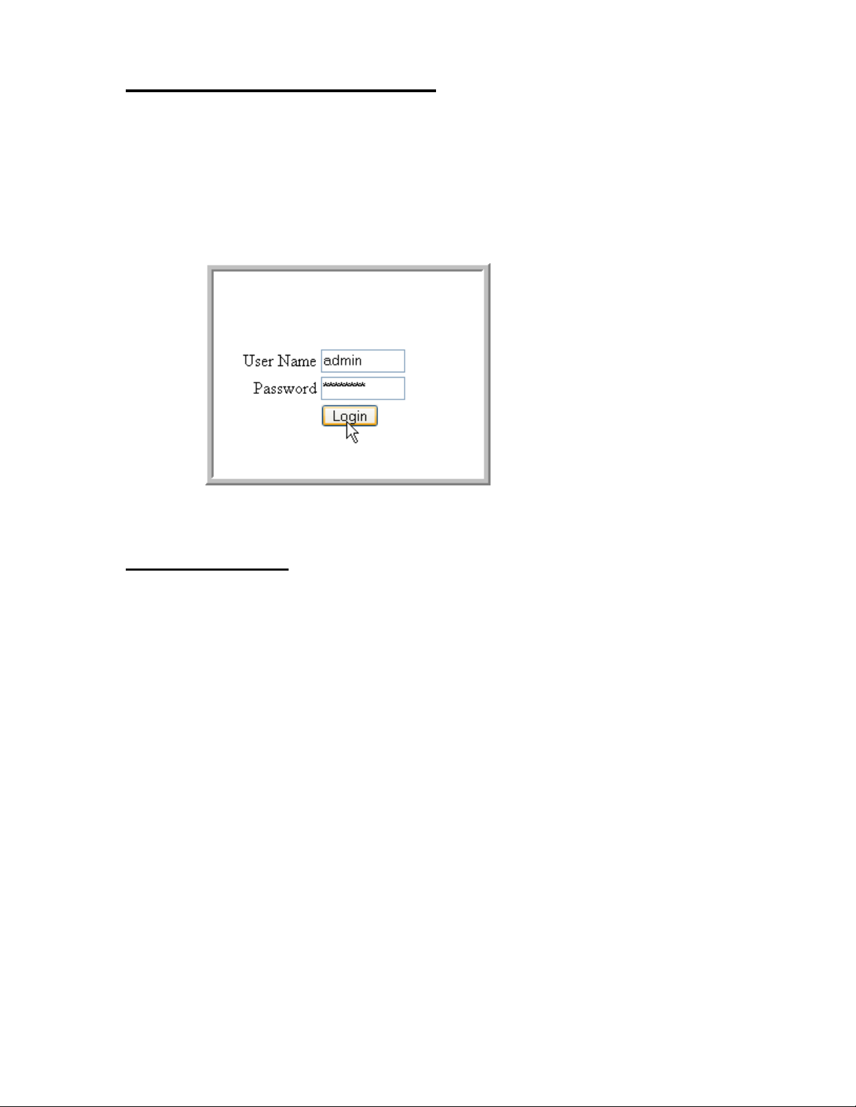
1. Enter the IP address of the switch in the Web browser address field.
2. Enter the appropria te Use r Na me an d Pa sswor d. The User Name and associated Pas swor d
are the same as those used for the terminal interface. Click on the Login button.
Figure 1. Web Interface Panel-Example
3. The System Description Menu displays as shown in Figure 2, with the navigation tree
appearing to the left of the screen.
4. Make a selection by clicking on the appropriate item in the navigation tree.
Web Page Layout
A Web interface panel for the switch Web page consists of three areas (Figure 2).
A banner graphic of the switch appears across the top of the panel.
The second area, a hierarchical-tree view appears to the left of the panel. The tree consists of a
combination of folders, subfolders, and configuration and status HTML pages. You can think
of the folders and subfolders as branches and the configuration and status HTML pages as
leaves. Only the selection of a leaf (not a folder or subfolder) will cause the display of a new
HTML page. A folder or subfolder has no corresponding HTML page.
The third area, at the bottom-right of the panel, displays the currently selected device
configuration status and/or the user configurable information that you have selected from the
tree view.
28 © 2001- 2008 D-Link Corporation. All Rights Reserved.
Page 29
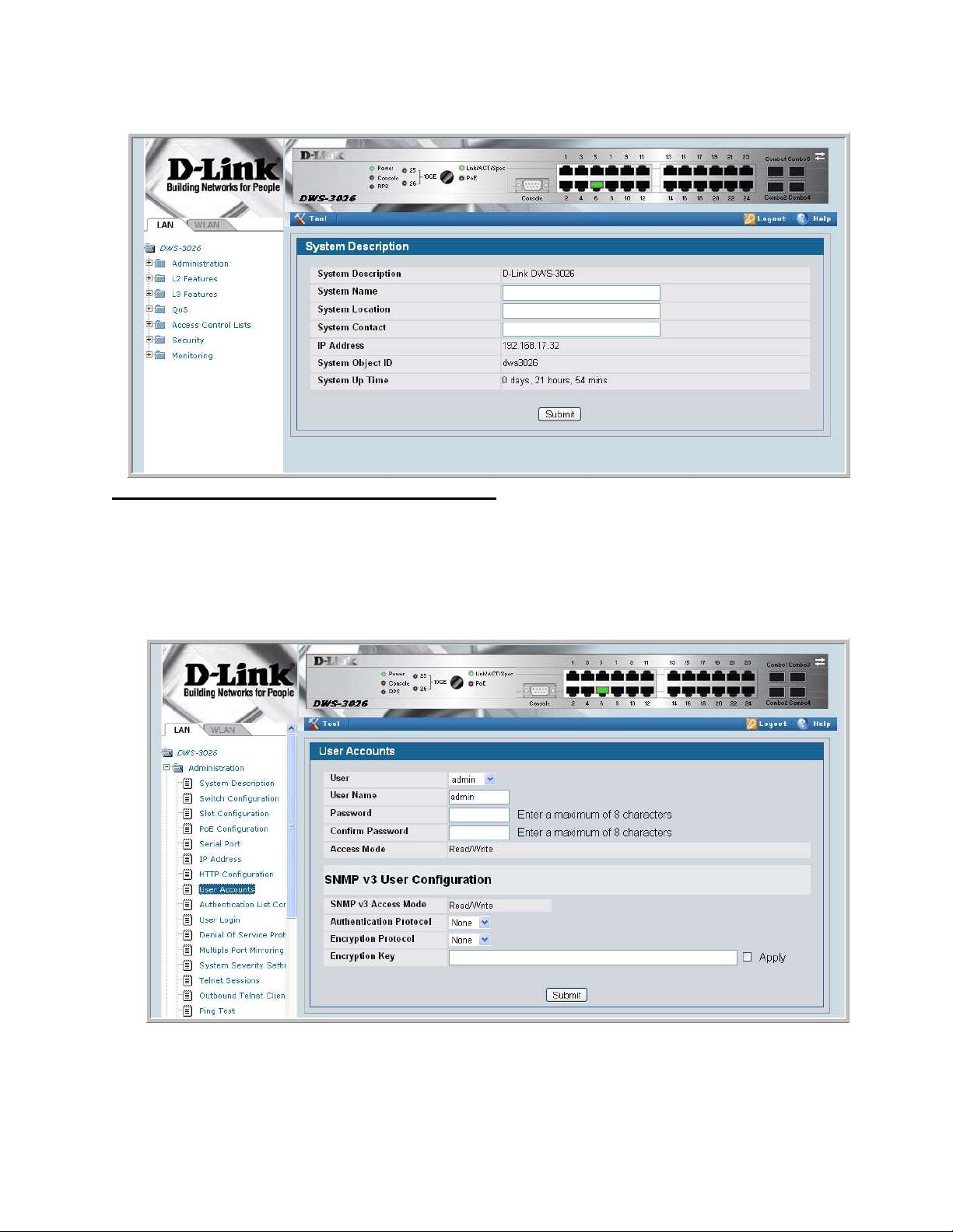
Figure 2. Web Interface Panel-Example
2 Using the Web Interface
Configuring an SNMP V3 User Profile
Configuring an SNMP V3 user profi le is a par t of use r c onfi gur at ion. Any user can connect to
the switch using th e SNMPv3 protocol, but for authent ica ti on and encryption, additional steps
are needed. Use the following steps to configure an SNMP V3 new user profile.
Figure 3. Configuring an SNMP V3 User Profile
1. From the LAN navigation menu, select LAN> Administration>User Accounts (see
Figure 3).
Starting the Web Interface 29
Page 30

Wired Configuration Guide
2. Using the User pull-down menu, select Create to create a ne w user.
3. Enter a new user name in the User Na me field.
4. Enter a new user password in the Password field and then retype it in the Confirm
Password field.
NOTE:If SNMPv3 Auth entication is to be implemented for th is user, set a password
5. If you do not need authentication, go to Step 9.
6. To enable authentica tion, use th e Authentication Protocol pull-down menu to select
either MD5 or SHA for the authentication protocol.
7. If you do not need encryption, go to Step 9.
8. T o e nable encrypt ion, u se the Encr yption Prot ocol pull -dow n menu t o sele ct DES f or the
encryption scheme. Then, enter an encryption code of eight or more alphanumeric
characters in the Encryp tion Key field.
9. Click Submit.
Command Buttons
of eight or more alphanumeric characters.
The following command buttons are used throughout the Web interface panels for the switch:
Save Pressing the Save button implements and saves the changes you just made.
Some settin gs may require you to reset the system in order for them to take
effect.
Refresh Pressing the Refresh button that appears next to the Apply button in Web
interface panels refreshes the data on the panel.
Submit Pressing the Submit button sends the updated configuration to the switch.
Configuration changes take effect immediately, but these changes are not
retained across a power cycle unless a save is performed.
30 © 2001- 2008 D-Link Corporation. All Rights Reserved.
Page 31

Virtual LANs
Adding Virtual LAN (VLAN) support to a Layer 2 switch offers some of the benefits of both
bridging and routing. Like a bridge, a VLAN switch forwards traffic based on the Layer 2
header, which is fast. Like a rout er, it partitions the network into logical segments, which
provides better administration, security and management of multicast traffic.
A VLAN is a set of end stations and the switch ports that connect them. You can have many
reasons for the logical division, for example, department or project membership. The only
physical requirement is that the end station, and the port to which it is connected, both belong
to the same VLAN.
Each VLAN in a network has an ass oci at ed VLAN I D , whic h ap pear s i n t he I EEE 802.1Q tag
in the Layer 2 header of packets transmitted on a VLAN. An end station may omit the tag, or
the VLAN portion of the ta g, in which case the first switch port to receive the pa cket may
either reject it or insert a tag using its default VLAN ID. A given port may handle traffic for
more than one VLAN, but it can only support one default VLAN ID.
3
Two features let you define packet filters that the switch uses as the matching criteria to
determine if a particular packet belongs to a particular VLAN.
• The IP-subnet Based VLAN feature lets you map IP addresses to VLANs by specifying a
source IP address, network mask, and the desired VLAN ID.
• The MAC-based VLAN feature let packets origin ating from end st atio ns become par t of a
VLAN according to source MAC address. To configure the feature, you specify a source
MAC address and a VLAN ID.
The Private Edge VLAN feature lets you set protection between ports located on the switch.
This means that a protected port cannot forward traffic to another protected port on the same
switch.
The feature does not provide protection between ports located on different switches.
31
Page 32

Wired Configuration Guide
VLAN Configuration Example
The diagra m in this section shows a switch with four ports configured to handle the traffic for
two VLANs. Port 0/2 handles tr affic for both VLANs, while port 0/1 is a member of VLAN 2
only, and ports 0/3 and 0/4 are members of VLAN 3 only. The script following the diagram
shows the commands you would use to configure the switch as shown in the diagram.
Figure 4. VLAN Example Network Diagram
5NIFIED3WITCH
0ORT
6,!.
0ORT
6,!.S
6,!.
Configuring a Guest VLAN
You can configure a Guest VLAN for clients to limit network access. If a client station fails to
authenticate using 802.1X or RADIUS, or if the client does not support 802.1X, then after the
authentication times out, the station is put on the guest VLAN configured for that switch port.
0ORT
6,!.
0ORT
6,!.
6,!.
For more information about how to configure a Guest VLAN for wired clients, see “Guest
VLAN” on page 39.
Configuring Dynamic VLAN Assignments
The software supports VLAN assignment for clients based on the RADIUS server
authentication. You need an external RADIUS server to use the dynamic VLAN assignment
feature. For information about how to configure the switch to allow dynamic VLAN
assignments, see “Configuring Dynamic VLAN Assignment” on page 41.
32 © 2001- 2008 D-Link Corporation. All Rights Reserved.
Page 33

CLI Examples
The following examples show how to create VLANs, as si gn ports to the VLANs, and ass ign a
VLAN as the default VLAN to a port.
Example #1: Create Two VLANs
Use the following commands to create two VLANs and to assi gn the VLAN IDs whil e leaving
the names blank.
(DWS-3024) #vlan database
(DWS-3024) (Vlan)#vlan 2
(DWS-3024) (Vlan)#vlan 3
(DWS-3024) (Vlan)#exit
Example #2: Assign Ports to VLAN2
This sequence shows how to assign ports to VLAN2, specify that frames will always be
transmitted tagged from all member ports, and that untagged frames will be rejected on
receipt.
3 Virtual LANs
(DWS-3024) #config
(DWS-3024) (Config)#interface 0/1
(DWS-3024) (Interface 0/1)#vlan participation include 2
(DWS-3024) (Interface 0/1)#vlan acceptframe vlanonly
(DWS-3024) (Interface 0/1)#exit
(DWS-3024) (Config)#interface 0/2
(DWS-3024) (Interface 0/2)#vlan participation include 2
(DWS-3024) (Interface 0/2)#vlan acceptframe vlanonly
(DWS-3024) (Interface 0/2)#exit
(DWS-3024) (Config)#exit
(DWS-3024) #config
(DWS-3024) (Config)#vlan port tagging all 2
(DWS-3024) (Config)#exit
Example #3: Assign Ports to VLAN3
This example shows how to assign the ports that will belong to VLAN 3, and to specify that
untagged frames will be accepted on port 0/4.
Note that port 0/2 belongs to both VLANs and that port 0/1 can never belong to VLAN 3.
(DWS-3024) #config
(DWS-3024) (Config)#interface 0/2
(DWS-3024) (Interface 0/2)#vlan participation include 3
(DWS-3024) (Interface 0/2)#exit
(DWS-3024) (Config)#interface 0/3
(DWS-3024) (Interface 0/3)#vlan participation include 3
(DWS-3024) (Interface 0/3)#exit
(DWS-3024) (Config)#interface 0/4
(DWS-3024) (Interface 0/4)#vlan participation include 3
(DWS-3024) (Interface 0/4)#exit
(DWS-3024) (Config)#
(DWS-3024) (Config)#exit
(DWS-3024) #config
(DWS-3024) (Config)#interface 0/4
(DWS-3024) (Interface 0/4)#vlan acceptframe all
CLI Examples 33
Page 34

Wired Configuration Guide
(DWS-3024) (Interface 0/4)#exit
(DWS-3024) (Config)#exit
Example #4: Assign VLAN3 as the Default VLAN
This example shows how to assign VLAN 3 as the default VLAN for port 0/2.
(DWS-3024) #config
(DWS-3024) (Config)#interface 0/2
(DWS-3024) (Interface 0/2)#vlan pvid 3
(DWS-3024) (Interface 0/2)#exit
(DWS-3024) (Config)#exit
Example #5: Assign IP Addresses to VLAN 2
(DWS-3024) #vlan database
(DWS-3024) (Vlan)#vlan association subnet 192.168.10.10 255.255.255.0 2
(DWS-3024) (Vlan)#exit
(DWS-3024) #show vlan association subnet
IP Address IP Mask VLAN ID
---------------- ---------------- -------
192.168.10.10 255.255.255.0 2
(DWS-3024) #
Web Interface
You can perform the same configuration in the CLI Examples section by using the Web
interface. To create VLANs and specify port participation, use the LAN> L2 Features >
VLAN> VLAN Configuration page.
Figure 5. VLAN Configuration
34 © 2001- 2008 D-Link Corporation. All Rights Reserved.
Page 35

3 Virtual LANs
T o spec if y the handli ng of untagg ed frames on re ceipt use the LAN> L2 Featur es > VLAN >
Port Configuration page.
Figure 6. VLAN Port Configuration
Private Edge VLANs
Use the Private Edge VLAN feature to prevent ports on the switch from forwarding traffic to
each other even if they are on the same VLAN.
• Protected ports cannot forward traffic to other protected ports in the same group, even if
they have the sa me VLAN membe rship. Pr otect ed port s can fo rward traf f ic to unprot ected
ports.
• Unprotected ports can forward traffic to both protected and unprotected ports.
You can also configure groups of protected ports. Each group’s configuration consists of a
name and a mask of ports. A por t can belong to only one set of protecte d ports. An un protecte d
port can be added to a group as a protected port.
The group name is configurable by the network administrator.
Use the switchport protected command to designate a port as protected. Use the show
switchport protected command to display a listing of the protected ports.
Private Edge VLANs 35
Page 36

Wired Configuration Guide
CLI Example
Example #1: switchport protected
(DWS-3024) #config
(DWS-3024) (Config)#interface 0/1
(DWS-3024) (Interface 0/1)#switchport protected ?
<cr> Press Enter to execute the command.
(DWS-3024) (Interface 0/1)#switchport protected
Example #2: show switchport protected
(DWS-3024) #show switchport protected
0/1
36 © 2001- 2008 D-Link Corporation. All Rights Reserved.
Page 37

802.1X Network Access Control
Port-based network acc ess control allows t he operation of a sys tem’ s port( s) to be controll ed to
ensure that access to its services is permitted only by systems that are autho rized to do so .
Port Access Control provides a means of preventing unauthorized access by supplicants or
users to the services offered by a System. Control ov er the access to a switch and the LAN to
which it is connected can be desirable in order to restrict access to publicly accessible bridge
ports or departmental LANs.
The Unified Switch achieves access control by enforcing authentication of supplicants that are
attached to an authenticator’s controlled ports. The result of the authentication process
determines whether the supplicant is authorized to access services on that controlled port.
A PAE (Port Access Entity) can adopt one of two roles within an access control interaction:
4
• Authenticator – Port that enforces authen tication befo re allowing access to serv ices avail-
able via that Port.
• Supplicant – Port that attempts to access services offered by the Authenticator.
Additionally, there exists a third role:
• Authentication server – Server that perf orms the auth entication function ne cessary to
check the credentials of the supplicant on behalf of the Authenticator.
Completion of an authen tication exchange requires all three roles. The Unified Switch
supports the authenticator role only, in which the PAE is responsible for communicating with
the supplicant. The authenticator PAE is also responsible for submitting information received
from the supplicant to the authentication server in order for the credentials to be check ed,
which determines the authorization state of the port. Depending on the outcome of the
authentication process, the authenticator PAE then controls the authorized/unauthorized state
of the controlled Port.
Authentication can be handled locally or via an external authentication server. Two are:
Remote Authentication Dial-In User Service (RADIUS) or Terminal Access Controller Access
Control System (TACACS+). The Unified Switch currently supports RADIUS for 802.1X.
RADIUS supports an accounting function to maintain data on service usages. Under RFC
2866, an extension was added to the RADIUS protocol giving the client the ability to deliver
accounting information about a user to an accounting server. Exchanges to the accounting
server follow similar guidelines as that of an authentication server but the flows are much
37
Page 38

Wired Configuration Guide
simpler. At the start of service for a user, the RADIUS client that is configured to use
accounting sends an accounting start packet specifying the type of service that it will deliver.
Once the server responds with an acknowledgement, the client periodically transmits
accounting data. At the end of service delivery, the client sends an accounting stop packet
allowing the server to update specified statistics. The server again responds with an
acknowledgement.
802.1x Network Access Control Example
This example configures a single RADIUS server used for authentication and accounting at
10.10.10.10. The shared secret is configured to be secret. The process creat es a new
authentication list, called radiusList, which uses RADIUS as the authentication method. This
authentication li st i s ass ociat ed with th e 802.1x defau lt l ogin. 8 02.1x por t bas ed access contr ol
is enabled for the system, and interface 0/1 is configured to be in force-authorized mode
because this is where the RADIUS server and protected network resources are located.
Figure 7. DWS-3000 with 802.1x Network Access Control
If a user, or supplicant, attempts to communicate via the switch on any interface except
interface 0/1, the system challenges the supplicant for login credentials. The system encrypts
the provided information and transmits it to the RADIUS server. If the RADIUS server grants
access, the system sets the 802.1x po rt stat e of the i nterf ace to aut hori zed an d the suppl icant is
able to access network resources.
config
radius server host auth 10.10.10.10
radius server key auth 10.10.10.10
secret
secret
radius server host acct 10.10.10.10
radius server key acct 10.10.10.10
secret
secret
radius accounting mode
authentication login radiusList radius
dot1x defaultlogin radiusList
dot1x system-auth-control
interface 0/1
dot1x port-control force-authorized
exit
exit
38 © 2001- 2008 D-Link Corporation. All Rights Reserved.
Page 39

Guest VLAN
The Guest VLAN feature allows a switch to provid e a distinguished ser vice to unauthenti cated
users. This feature provides a mechanism to allow visitors and contractors to have network
access to re ach external network w ith no ability to surf internal LAN.
When a client that does not support 802.1X is connected to an unauthorized port that is
802.1X-enabled, the client does not respond to the 802.1X requests from the switch.
Therefore, the port remains in the unauthor ized stat e, and the client is not grante d access to the
network. If a guest VLAN is configured for that port, then the port is placed in the configured
guest VLAN and the port is moved to the authorized state, allowing access to the client.
Client devices that are 802.1X-supplicant-enabled authenticate with the switch when they are
plugged into the 802.1X-enabled switch port. The switch verifies the credentials of the client
by communicating with an authentication server. If the credentials are verified, the
authentication server informs the switch to 'unblock' the switch port and allows the client
unrestricted access to the network ; i.e., the client is a member of an internal VLAN.
Guest VLAN Supplicant mode is a global configura tion for al l the ports on the switch. When a
port is configure d for Gue st VL AN in th is mode, i f a cl ient f ails authen ti catio n on the p ort, t he
client is assigned to the guest VLAN configured on that port. The port is assigned a Guest
VLAN ID and is moved to the authorized status. Disa bling the suppli cant mo de does not cle ar
the ports that are already authorized and assigned Guest VLAN IDs.
4 802.1X Network Access Control
Configuring the Guest VLAN by Using the CLI
To enable the Guest VLAN Supplicant Mode, use the dot1x guest-vlan supplicant
command in Global Config mode.
To configure a VLAN as guest VLAN on a per port basis, enter the Interface Config mode for
the port and use the
dot1x guest-vlan <vlan-id> command.
Guest VLAN 39
Page 40

Wired Configuration Guide
Configuring the Guest VLAN by Using the Web Interface
To enable the Guest VLAN features by using the Web interface, use the LAN> Security >
802.1x > 802.1X Setting page.
To configure the Guest VLAN settings on a port, use the LAN> Security > 802.1x > 802.1X
Port Setting page.
40 © 2001- 2008 D-Link Corporation. All Rights Reserved.
Page 41

4 802.1X Network Access Control
Configuring Dynamic VLAN Assignment
The software also supports VLAN assignment for clients based on the RADIUS server
authentication.
To enable the switch to accept VLAN assignment by the RADIUS server, use the
authorization network radius command in Global Config mode.
T o e nable the VLAN Ass ignme nt Mode by usin g the Web interface, use the LAN> Security >
802.1x > 802.1X Setting page and select Enable from the VLAN Assignment Mode menu.
Configuring Dynamic VLAN Assignment 41
Page 42

Wired Configuration Guide
42 © 2001- 2008 D-Link Corporation. All Rights Reserved.
Page 43

Storm Control
A traffic storm is a condition that occurs when incoming packets flood the LAN, which creates
performance degradati on i n the net w ork . The Uni fi ed Swi tc h’s Storm Control feature protects
against this condition.
The Unified Switch provides broadcast, multicast, and unicast storm recovery for individual
interfaces or for all interfaces.
Unicast Storm Control protects against traffic whose MAC addresses are not known by the
system.
For broadcast, multicast, and unicast storm control, if the rate of traffic ingressing on an
interface increases beyond the configured threshold for that type, the traffic is dropped.
5
To configure storm control, you’ll enable the feature for all interfaces or for individual
interfaces, and you’ll set the threshold (storm control level) beyond which the broadcast,
multicast, or unicast traffic will be dropped.
Configuring a storm-control level also enables that form of storm-control. Disabling a stormcontrol level (using the “no” version of the command) sets the storm-control level back to
default value and disables that form of storm-control. Using the “no” version of the “stormcontrol” command (not st atin g a “leve l”) dis ables tha t form of s torm-c ontrol but maintai ns the
configured “level” (to be activ e next ti me that form of storm-control is enabled).
CLI Example
Example #1: Set Broadcast Storm Control for All Interfaces
(DWS-3024) #config
(DWS-3024) (Config)#storm-control broadcast ?
all Configure storm-control features for all ports.
(DWS-3024) (Config)#storm-control broadcast all ?
<cr> Press Enter to execute the command.
level Configure storm-control thresholds.
(DWS-3024) (Config)#storm-control broadcast all level ?
CLI Example 43
Page 44

Wired Configuration Guide
<rate> Enter the storm-control threshold as percent of port
speed.
(DWS-3024) (Config)#storm-control broadcast all level 7
(DWS-3024) (Config)#exit
(DWS-3024)
Example #2: Set Multicast Storm Control for All Interfaces
(DWS-3024) #config
(DWS-3024) (Config)#storm-control multicast all ?
<cr> Press Enter to execute the command.
level Configure storm-control thresholds.
(DWS-3024) (Config)#storm-control multicast all level 8
(DWS-3024) (Config)#exit
(DWS-3024) #
Example #3: Set Unicast Storm Control for All Interfaces
(DWS-3024) #config
(DWS-3024) (Config)#storm-control unicast all level 5
(DWS-3024) (Config)#exit
(DWS-3024) #
44 © 2001- 2008 D-Link Corporation. All Rights Reserved.
Page 45

Web Interface
The Storm Control configuration options are available on the Port Configuration Web page
under the Administration folder.
Figure 8. Port Configuration (Storm Control)
5 Storm Control
Web Interface 45
Page 46

Wired Configuration Guide
46 © 2001- 2008 D-Link Corporation. All Rights Reserved.
Page 47

Trunking (Link Aggregation)
This section shows how to use the Trunking feature (also known as Link Aggregation) to
configure port-channels by using the CLI and the Web interface.
The Link Aggregation (LAG) feature allows the switch to treat multiple physical links
between two end-points as a singl e logi cal link called a port-channel. All of the physi cal links
in a given port-channel must operate in full-duplex mode at the same speed.
You can use the feature to directly connect two switches when the traffic between them
requires high bandwidth and reliability, or to provide a higher bandwidth connection to a
public network.
You can configure the port-channels as either dynamic or static. Dynamic configuration uses
the IEEE 802.3ad standard, which provides for the periodic exchanges of LACPDUs. Static
configuration is used when connecting the switch to an external switch that does not support
the exchange of LACPDUs.
6
The feature offers the following benefits:
• Increased reliability and avai labil ity - - if on e of th e phy sical links in the port-cha nnel g oes
down, traffic is dynamically and transparently reassigned to one of the other physical
links.
• Increased bandwidth -- the aggregated physical links deliver higher bandwidth than each
individual link.
• Incremental increase in bandwidth -- A physical upgrade could produce a 10-times
increase in bandwidth; LAG produc es a two- or fiv e- ti mes inc re ase , usef ul i f only a small
increase is needed.
Management functions treat a port-channel as if it were a single physical port.
You can include a port- channel in a VLAN. You can configure more than one por t-cha nnel fo r
a given switch.
CLI Example
The following shows an example of configuring the Unified Switch to support Link
Aggregation (LAG) to a server and to a Layer 2 switch.
CLI Example 47
Page 48

Wired Configuration Guide
Figure 9 shows the example network.
Figure 9. LAG/Port-channel Example Network Diagram
3ERVER
0ORT
,!'?
0ORT
,!'?
3UBNET
0ORT
,!'?
5NIFIED3WITCH
0ORT
,!'?
,AYER3WITCH
Example 1: Create two port-channels:
(DWS-3024) #config
(DWS-3024) (Config)#port-channel lag_10
(DWS-3024) (Config)#port-channel lag_20
(DWS-3024) (Config)#exit
Use the show port-channel all command to show the logical interface ids you will use to
identify the port- channels i n subseque nt commands. Ass ume that la g_10 is ass igned id 3/ 1 and
lag_20 is assigned id 3/2.
48 © 2001- 2008 D-Link Corporation. All Rights Reserved.
3UBNET3UBNET
Page 49

6 Trunking (Link Aggregation)
(DWS-3024) #show port-channel all
Port- Link
Log. Channel Adm. Trap STP Mbr Port Port
Intf Name Link Mode Mode Mode Type Ports Speed Active
------ ------------- ----- ---- ---- ------ ------- ------ --------- -----3/1 lag_10 Down En. En. Dis. Dynamic
3/2 lag_20 Down En. En. Dis. Dynamic
Example 2: Add the physical ports to the port-channels:
(DWS-3024) #config
(DWS-3024) (Config)#interface 0/2
(DWS-3024) (Interface 0/2)#addport 3/1
(DWS-3024) (Interface 0/2)#exit
(DWS-3024) (Config)#interface 0/3
(DWS-3024) (Interface 0/3)#addport 3/1
(DWS-3024) (Interface 0/3)#exit
(DWS-3024) (Config)#exit
(DWS-3024) #config
(DWS-3024) (Config)#interface 0/8
(DWS-3024) (Interface 0/8)#addport 3/2
(DWS-3024) (Interface 0/8)#exit
(DWS-3024) (Config)#interface 0/9
(DWS-3024) (Interface 0/9)#addport 3/2
(DWS-3024) (Interface 0/9)#exit
(DWS-3024) (Config)#exit
Example 3: Enable both port-channels.
By default, the system enables link trap notification
(DWS-3024) #config
(DWS-3024) (Config)#port-channel adminmode all
(DWS-3024) (Config)#exit
At this point, the LAGs could be added to the default management VLAN.
CLI Example 49
Page 50

Wired Configuration Guide
Web Interface Configuration - LAGs/Port-channels
To perform the same configuration using the Web interface, use the LAN> L2 Features >
Trunking > Configuration page.
Figure 10. Trunking Configuration
To create the port-channels, specify port participation and enable Link Aggregation (LAG)
support on the switch.
50 © 2001- 2008 D-Link Corporation. All Rights Reserved.
Page 51

IGMP Snooping
This section describes th e Internet Group Ma nagement Protocol (IGMP) feature : IGMPv3 and
IGMP Snooping. The IGMP Snooping feature enables the switch to monitor IGMP
transactions betwee n hos ts and r outers. It can hel p c onserve bandwidt h by all owing t he swit ch
to forward IP multicast t raffic only to co nnected hosts that reque st multicast traffic.
Overview
IGMP:
• Uses Version 3 of IGMP
• Includes snooping
• Snooping can be enabled per VLAN
7
CLI Examples
The following are examples of the commands used in the IGMP Snooping feature.
Example #1: show igmpsnooping
(DWS-3024) #show igmpsnooping ?
<cr> Press Enter to execute the command.
<slot/port> Enter interface in slot/port format.
mrouter Display IGMP Snooping Multicast Router information.
<1-3965> Display IGMP Snooping valid VLAN ID information.
(DWS-3024) #show igmpsnooping
Admin Mode...............................Enable
Multicast Control Frame Count............0
Interfaces Enabled for IGMP Snooping.....0/10
Vlans enabled for IGMP snooping..........20
Overview 51
Page 52

Wired Configuration Guide
Example #2: show mac-address-table igmpsnooping
(DWS-3024) #show mac-address-table igmpsnooping ?
<cr> Press Enter to execute the command.
(DWS-3024) #show mac-address-table igmpsnooping
MAC Address Type Description Interfaces
----------------------- ------- ------------ ----------00:01:01:00:5E:00:01:16 Dynamic Network Assist Fwd: 0/47
00:01:01:00:5E:00:01:18 Dynamic Network Assist Fwd: 0/47
00:01:01:00:5E:37:96:D0 Dynamic Network Assist Fwd: 0/47
00:01:01:00:5E:7F:FF:FA Dynamic Network Assist Fwd: 0/47
00:01:01:00:5E:7F:FF:FE Dynamic Network Assist Fwd: 0/47
Example #3: set igmp (Global Config Mode)
(DWS-3026) (Config)#set igmp ?
<cr> Press enter to execute the command.
groupmembership-interval Configure IGMP Group Membership Interval
(secs).
interfacemode Enable/Disable IGMP Snooping.
maxresponse Configure IGMP Max Response time (secs).
mcrtrexpiretime Sets the Multicast Router Present Expiration
time on the system.
(DWS-3026) (Config)#set igmp
Example #4: set igmp (Interface Config Mode)
(DWS-3026) (Config)#interface 0/2
(DWS-3026) (Interface 0/2)#set igmp ?
<cr> Press enter to execute the command.
fast-leave Enable/Disable Fast-Leave on a selected
interface
groupmembership-interval Configure IGMP Group Membership Interval
(secs).
maxresponse Configure IGMP Max Response time (secs).
mcrtrexpiretime Sets the Multicast Router Present Expiration
time on
the system.
mrouter Configure Multicast Router port.
(DWS-3026) (Interface 0/2)#set igmp
52 © 2001- 2008 D-Link Corporation. All Rights Reserved.
Page 53
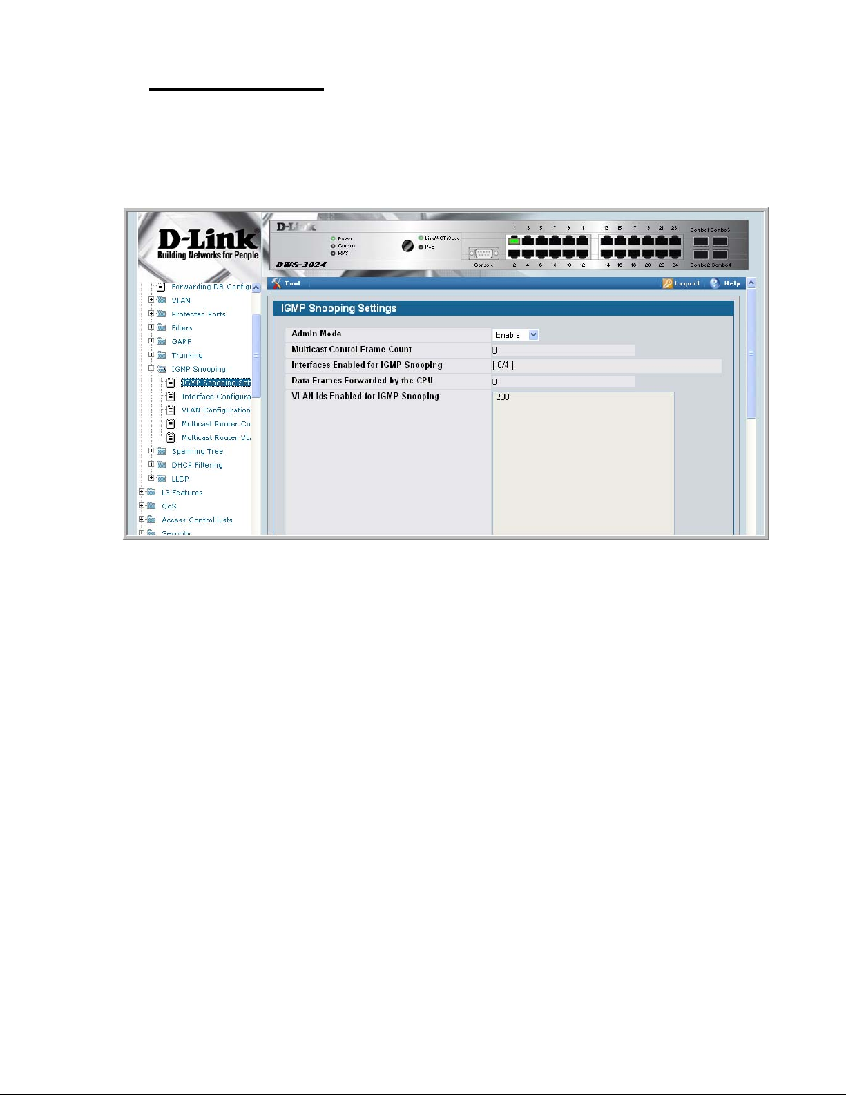
Web Examples
The following web pages are used in the IGMP Snooping feature. Click Help for more
information on the web interface.
Figure 11. IGMP Snooping - Global Configuration and Status Page
7 IGMP Snooping
Web Examples 53
Page 54

Wired Configuration Guide
Figure 12. IGMP Snooping - Interface Configuration Page
Figure 13. IGMP Snooping VLAN Configuration
54 © 2001- 2008 D-Link Corporation. All Rights Reserved.
Page 55

Figure 14. IGMP Snooping - VLAN Status Page
7 IGMP Snooping
Figure 15. IGMP Snooping - Multicast Router Statistics Page
Web Examples 55
Page 56

Wired Configuration Guide
Figure 16. IGMP Snooping - Multicast Router Configur ation Page
Figure 17. IGMP Snooping - Multicast Router VLAN Statistics Page
56 © 2001- 2008 D-Link Corporation. All Rights Reserved.
Page 57

Figure 18. IGMP Snooping - Multicast Router VLAN Configuration Page
7 IGMP Snooping
Web Examples 57
Page 58

Wired Configuration Guide
58 © 2001- 2008 D-Link Corporation. All Rights Reserved.
Page 59

Port Mirroring
This section describes the Port Mirroring feature, which can serve as a diagnostic tool,
debugging tool, or means of fending off attacks.
Overview
Port mirroring selects network traffic from specific ports for analysis by a network analyzer,
while allowing the same traffic to be switched to its destination. You can configure many
switch ports as source ports and one switch port as a destination port. You can also configure
how traffic is mirrored on a source port. Packets received on the source port, transmitted on a
port, or both received and transmitted, can be mirrored to the destination port.
8
CLI Examples
The following are examples of the commands used in the Port Mirroring feature.
Example #1: Set up a Port Mirroring Session
The following command sequence enables port mirroring and specifies a source and
destination ports.
(DWS-3024) #config
(DWS-3024) (Config)#monitor session 1 mode
(DWS-3024) (Config)#monitor session 1 source interface 0/7 ?
<cr> Press Enter to execute the command.
rx Monitor ingress packets only.
tx Monitor egress packets only.
(DWS-3024) (Config)#monitor session 1 source interface 0/7
(DWS-3024) (Config)#monitor session 1 destination interface 0/8
(DWS-3024) (Config)#exit
Overview 59
Page 60

Wired Configuration Guide
Example #2: Show the Port Mirroring Session
(DWS-3024) #show monitor session 1
Session ID Admin Mode Probe Port Mirrored Port Type
---------- ---------- ---------- ------------- ----1 Enable 0/8 0/7 Rx,Tx
(DWS-3024) #Monitor session ID “1” - “1” is a hardware limitation.
Example #3: Show the Status of All Ports
(DWS-3024) #show port all
Intf Type Mode Mode Status Status Trap Mode
---- ---- ------ -------- -------- ------ ---- ---0/1 Enable Auto Up Enable Enable
0/2 Enable Auto Down Enable Enable
0/3 Enable Auto Down Enable Enable
0/4 Enable Auto Down Enable Enable
0/5 Enable Auto Down Enable Enable
0/6 Enable Auto Down Enable Enable
0/7 Mirror Enable Auto Down Enable Enable
0/8 Probe Enable Auto Down Enable Enable
0/9 Enable Auto Down Enable Enable
0/10 Enable Auto Down Enable Enable
Admin Physical Physical Link Link LACP
Example #4: Show the Status of the Source and Destination Ports
Use this command for a specific port. The output shows whether the port is the mirror or the
probe port, what is enabled or disabled on the port, etc.
(DWS-3024) #show port 0/7
Intf Type Mode Mode Status Status Trap Mode
---- ---- ------ -------- -------- ------ ---- ---0/7 Mirror Enable Auto Down Enable Enable
(DWS-3024) #show port 0/8
Intf Type Mode Mode Status Status Trap Mode
---- ---- ------ -------- -------- ------ ---- ---0/8 Probe Enable Auto Down Enable Enable
Admin Physical Physical Link Link LACP
Admin Physical Physical Link Link LACP
60 © 2001- 2008 D-Link Corporation. All Rights Reserved.
Page 61

Web Examples
The following web pages are used with the Port Mirroring feature.
Figure 19. Multiple Port Mirroring
8 Port Mirroring
Figure 20. Multiple Port Mirroring - Add Source Ports
Web Examples 61
Page 62

Wired Configuration Guide
Figure 21. System - Port Utilization Summary
62 © 2001- 2008 D-Link Corporation. All Rights Reserved.
Page 63

Port Security
This section describes the Port Security feature.
Overview
Port Security:
• Allows for limiting the number of MAC addresses on a given port.
• Packets that have a matchin g MAC a ddress (secure packets) are f or warded; all other pack-
ets (unsecure packets) are restricted.
• Enabled on a per port basis.
• When locked, only packets with allowable MAC address will be forwarded.
• Supports both dynamic and static.
• Implement two traffic filtering methods. These methods can be used concurrently.
- Dynamic Locking - User specifies the maximum number of MAC addresses that can
be learned on a port. After the limit is reached, additional MAC addresses are not
learned. Only frames with an allowable source MAC address are forwarded.
- Static Locking - User manually specifies a list of static MAC addresses for a port.
Dynamically locked addresses can be converted to statically locked addresses.
9
Operation
Port Security:
• Helps secure network by preventing unknown devices from forwarding packets.
• When link goes down, all dynamically locked addresses are ‘freed.’
• If a s pecific MAC address is to b e set for a port, set the dyna mic entries to 0, then only
allow packets with a MAC address matching the MAC address in the static list.
• Dynamically locked MAC addresses are ag ed out if a nother pac ket with t hat addres s is not
seen withi n the age-out time. The user can set the time-out value.
• Dynamically locked MAC addresses are eligible to be learned by another port.
• Static MAC addresses are not eligible for aging.
• Dynamically locked addresses can be converted to statically locked addresses.
Overview 63
Page 64

Wired Configuration Guide
CLI Examples
The following are examples of the commands used in the Port Security feature.
Example #1: show port security
(DWS-3024) #show port-security ?
<cr> Press Enter to execute the command.
all Display port-security information for all
<slot/port> Display port security information for a
dynamic Display dynamically learned MAC addresses.
static Display statically locked MAC addresses.
violation Display the source MAC address of the last
Example #2: show port security on a specific interface
interfaces
specific interface.
packet that was discarded on a locked port.
(DWS-3024) #show port-security 0/10
Admin Dynamic Static Violation
Intf Mode Limit Limit Trap Mode
------ ------- ---------- --------- ---------0/10 Disabled 600 20 Disabled
Example #3: (Config) port security
(DWS-3024) (Config) #port-security ?
<cr> Press Enter to execute the command.
(DWS-3024) (Config) #port-security
64 © 2001- 2008 D-Link Corporation. All Rights Reserved.
Page 65
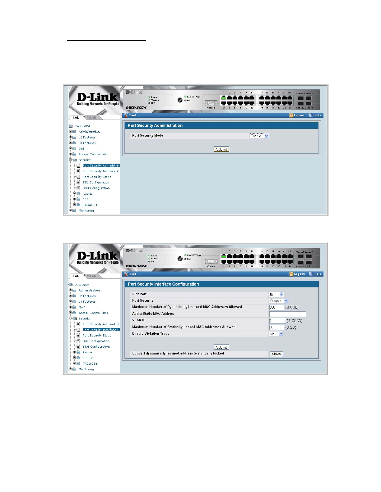
Web Examples
The following Web pages are used in the Port Security feature.
Figure 22. Port Security Administration
9 Port Security
Figure 23. Port Security Interface Configuration
Web Examples 65
Page 66

Wired Configuration Guide
Figure 24. Port Security Statically Configured MAC Addresses
To view Port Security status information, navigate to LAN> Monitoring > Port Security
from the navigation panel.
Figure 25. Port Security Dynamically Learned MAC Addresses
66 © 2001- 2008 D-Link Corporation. All Rights Reserved.
Page 67

Figure 26. Port Security Violation Status
9 Port Security
Web Examples 67
Page 68

Wired Configuration Guide
68 © 2001- 2008 D-Link Corporation. All Rights Reserved.
Page 69

Link Layer Discovery Protocol
The Link Layer Discover y Protocol (LLDP) feature allows i ndi vidual interfaces on the switc h
to advertise major capabilities and physical descriptions. Network managers can view this
information and identify system topology and detect bad configurations on the LAN.
LLDP has separately configurable transmit and receive functions. Interfaces can transmit and
receive LLDP information.
CLI Examples
Example #1: Set Global LLDP Parameters
10
Use the following sequence to specify switch-wide notification interval and timers for all
LLDP interfaces.
(DWS-3024) #config
(DWS-3024) (Config)#lldp ?
notification-interval Configure minimum interval to send remote data
change notifications
timers Configure the LLDP global timer values.
(DWS-3024) (Config)#lldp notification-interval ?
<interval-seconds> Range <5 - 3600> seconds.
(DWS-3024) (Config)#lldp notification-interval 1000
(DWS-3024) (Config)#lldp timers ?
<cr> Press Enter to execute the command.
hold The interval multiplier to set local LLDP data TTL.
interval The interval in seconds to transmit local LLDP data.
reinit The delay before re-initialization.
(DWS-3024) (Config)#lldp timers hold 8 reinit 5
(DWS-3024) (Config)#exit
CLI Examples 69
Page 70

Wired Configuration Guide
(DWS-3024) #
Example #2: Set Interface LLDP Parameters
The following commands configure interface 0/10 to transmit and receive LLDP information.
(DWS-3024) #config
(DWS-3024) (Config)#interface 0/10
(DWS-3024) (Interface 0/10)#lldp ?
notification Enable/Disable LLDP remote data change notifications.
receive Enable/Disable LLDP receive capability.
transmit Enable/Disable LLDP transmit capability.
transmit-mgmt Include/Exclude LLDP management address TLV.
transmit-tlv Include/Exclude LLDP optional TLV(s).
(DWS-3024) (Interface 0/10)#lldp receive
(DWS-3024) (Interface 0/10)#lldp transmit
(DWS-3024) (Interface 0/10)#lldp transmit-mgmt
(DWS-3024) (Interface 0/10)#exit
(DWS-3024) (Config)#exit
(DWS-3024) #
Example #3: Show Global LLDP Parameters
(DWS-3024) #show lldp
LLDP Global Configuration
Transmit Interval............................ 30 seconds
Transmit Hold Multiplier..................... 8
Reinit Delay................................. 5 seconds
Notification Interval........................ 1000 seconds
(DWS-3024) #
Example #4 Show Interface LLDP Parameters
(DWS-3024) #show lldp interface 0/10
LLDP Interface Configuration
Interface Link Transmit Receive Notify TLVs Mgmt
--------- ------ -------- -------- -------- ------- ---0/10 Down Enabled Enabled Disabled Y
TLV Codes: 0- Port Description, 1- System Name
2- System Description, 3- System Capabilities
(DWS-3024) #
70 © 2001- 2008 D-Link Corporation. All Rights Reserved.
Page 71

10 Link Layer Discovery Protocol
Using the Web Interface to Configure LLDP
The LLDP menu page contains links to the following features:
• LLDP Configuration
• LLDP Statistics
• LLDP Connections
• LLDP Configuration
Use the LLDP Global Configuration page to specify LLDP parameters.
Figure 27. LLDP Global Configuration
The LLDP Global Configuration page contains the following fields:
• Transmit Interval (1-32768) — Specifies the interval at which frames are transmitted.
The default is 30 seconds.
• Hold Multiplier (2-10) — Specifies multiplier on the transmit interval to assign to TTL.
Default is 4.
• Re-Initializat ion Delay (1-10) — Specifies delay before a re-initialization. Default is 2 sec-
onds.
• Notification Interval (5-3600) — Limits the transmission of notifications. The default is
5 seconds.
Using the Web Interface to Configure LLDP 71
Page 72

Wired Configuration Guide
Use the LLDP Interface Configuration screen to specify trans mit and recei ve functions for
individual interfaces.
Figure 28. LLDP Interface Configuration
Interface Parameters
• Interface — Specifies the port to be affected by these parameters.
• Transmi t Mode — Enables or disables the transmit function. The default is disabled.
• Receive Mode — Enables or disables the receive function. The default is disabled.
• Transmit Ma nagement Informati on — Enables or disables tr ansmission of management
address instance. Default is disabled.
• Notification Mode — Enables or disables remote change notifications. The default is dis-
abled.
• Included TLVs — Selects TLV information to transmit. Choices include System Name,
System Capabilities, System Description, and Port Description.
72 © 2001- 2008 D-Link Corporation. All Rights Reserved.
Page 73

Figure 29. LLDP Interface Summary
10 Link Layer Discovery Protocol
Figure 30. LLDP Statis tic s
You can also use the pages in the LAN> Monitoring > LLDP Status folder to view
information about local and remote devices.
Using the Web Interface to Configure LLDP 73
Page 74

Wired Configuration Guide
74 © 2001- 2008 D-Link Corporation. All Rights Reserved.
Page 75

Denial of Service Attack Protection
This section describes the D-Link DWS-3000 switch’s Denial of Service Protection feature.
Overview
Denial of Service:
• Spans two categories:
- Protection of the Unified Switch
- Protection of the network
• Protects against the exploitation of a number of vulnera biliti es which would make t he host
or network unstable
• Compliant with Nessus. Nessus is a widely-used vulnerability assessment tool.
• The Unified Switch provides a number of features that help a network administrator pro-
tect networks against DoS attacks.
11
CLI Examples
Enter from Global Config mode:
(DWS-3024) #configure
(DWS-3024) (Config)#dos-control sipdip
(DWS-3024) (Config)#dos-control firstfrag
(DWS-3024) (Config)#dos-control tcpfrag
(DWS-3024) (Config)#dos-control l4port
(DWS-3024) (Config)#dos-control icmp
(DWS-3024) (Config)#exit
(DWS-3024) #show dos-control
SIPDIP Mode.................................... Enable
Overview 75
Page 76

Wired Configuration Guide
First Fragment Mode............................ Enable
Min TCP Hdr Size............................... 20
TCP Fragment Mode.............................. Enable
TCP Flag Mode.................................. Disable
L4 Port Mode................................... Enable
ICMP Mode...................................... Enable
Max ICMP Pkt Size.............................. 512
Web Interface
You can configure the Denial of Service feature from the Denial of Service Protection
Configuration page.
Figure 31. Denial of Service Protection Configuration
76 © 2001- 2008 D-Link Corporation. All Rights Reserved.
Page 77

Port Routing
The first networks were small enough for the end stations to communicate directly. As
networks grew, Layer 2 bridging was used to segregate traffic, a technology that worked well
for unicast traffic, but had problems coping with large quantities of multicast packets. The
next major development was routing, wher e packe ts were ex amin ed and redir ected at Layer 3.
End stations needed to know how to reach their nearest router, and the routers had to
understand the network topology so that they could forward traffic. Although bridges tended
to be faster than routers, using routers allowed the network to be partitioned into logical
subnetworks, which restri cted mult icast tr aff ic and also fac ilitated th e develop ment of securi ty
mechanisms.
An end station specifies the dest ination station’ s Laye r 3 addre ss in the packet’s IP header but
sends the packet to the MAC address of a router. When the Layer 3 router receives the packet,
at a minimum it does the following:
12
• Looks up the Layer 3 address in its address table to determine the outbound port
• Updates the Layer 3 header
• Recreates the Layer 2 header
The router’s IP address is often statically configured in the end station, although the Unified
Switch supports DHCP that allow the address to be assigned dynamically. You may assign
static entries in the routing tables used by the router.
Port Routing Configuration
The Unified Switch always supports Layer 2 bridging, but Layer 3 routing must be explicitly
enabled, first for the Unified Switch as a whole, and then for each port which is to participate
in the routed network.
The configuration commands used in this section’s example enable IP routing on ports 0/2, 0/
3, and 0/5. The router ID is set to the Unified Switch’s management IP address, or to that of
any active router interface if the management address is not configured.
After you’ve issued the routing configuration commands, the following functions are active:
• IP Forwarding - responsible for forwarding received IP packets.
Port Routing Configuration 77
Page 78

Wired Configuration Guide
• ARP Mapping - responsible for maintaining the ARP Table used to correlate IP and MAC
addresses. The ta ble co ntains both static entries an d en tries dynamically updated base d on
information in received ARP frames.
• Routing Table Object - responsible for maintaining the routing table populated by local
and static routes.
CLI Examples
The diagram in this section shows a Unified Switch configured for port routing. It connects
three differe nt subn ets, each c onnected to a dif ferent p ort. The scr ipt sh ows the commands y ou
would use to configure a Unified Switch to provide the port routing support shown in the
diagram.
Figure 32. Port Routing Example Network Diagram
0ORT
5NIFIED3WITCH
ACTINGASAROUTER
0ORT
3UBNET
0ORT
Example 1. Enabling routing for the Switch
Use the following command to enable routing for the switch. Execution of the command
enables IP forwarding by default.
3UBNET
3UBNET
config
ip routing
exit
78 © 2001- 2008 D-Link Corporation. All Rights Reserved.
Page 79

Example 2. Enabling Routing for Ports on the Switch
Use the following commands to enable routing for ports on the switch. The default link-level
encapsulation format is Ethernet. Configure the IP addresses and subnet masks for the ports.
Network directed broadcast frames are dropped and the maximum transmission unit (MTU)
size is 1500 bytes.
config
interface 0/2
routing
ip address 192.150.2.2 255.255.255.0
exit
exit
config
interface 0/3
routing
ip address 192.130.3.1 255.255.255.0
exit
exit
config
interface 0/5
routing
ip address 192.64.4.1 255.255.255.0
exit
exit
12 Port Routing
CLI Examples 79
Page 80

Wired Configuration Guide
Using the Web Interface to Configure Routing
Use the following screens to perform the same configuration using the Graphical User
Interface:
To enable routing for the switch, as shown i n Exampl e 1. Enabling routing for the Switch, use
the LAN> L3 Features> IP > Configuration page.
Figure 33. IP Configuration
To configure routing on ea ch interface, as shown in Examp le 2. Enabli ng Routing for Ports on
the Switch, use the LAN> L3 Features > IP > Interface Configuration page.
Figure 34. IP Interface Configuration
80 © 2001- 2008 D-Link Corporation. All Rights Reserved.
Page 81

VLAN Routing
You can configure the Unified Switch with some ports supporting VLANs and some
supporting routing. You can also configure the Unified Switch to allow traffic on a VLAN to
be treated as if the VLAN were a router port.
When a port is enabled for bri dgi ng ( de fault) rather than routing, all nor mal bri dge processing
is performed for an inbound packet, which is then associated with a VLAN. Its MAC
Destination Address (MAC DA) and VLAN ID are used to search the MAC address table. If
routing is enabled for the VLAN and the MAC DA of an inbound unicast packet is that of the
internal bridge-r outer inter face, the packet will be rout ed. An i nbound mul ticas t pack et wil l be
forwarded to all ports in the VLAN, plus the internal bridge-router interface if it was received
on a routed VLAN.
Since a port can be configured to belong to more than one VLAN, VLAN routing might be
enabled for all of t he VLANs on the por t, or for a subset. VLAN Routing can be use d t o allow
more than one physical po rt to r esi de o n the same subnet. It could also be used when a VLAN
spans multiple physical networks, or when additional segmentation or security is required.
13
This section show s h ow t o c onfigure the Unified Switch to support VLAN routing. A port can
be either a VLAN port or a router port, but not both. However, a VLAN port may be part of a
VLAN that is itself a router port.
VLAN Routing Configuration
This section provides an example of how to configure the Unified Switch to support VLAN
routing. The configuration of the VLAN router port is similar to that of a physical port. The
main difference is that, after the VLAN has been created, you must use the show ip vlan
command to determine the VLAN’s interface ID so that you can use it in the router
configuration commands.
CLI Examples
The diagram in this section shows a Unified Switch configured for VLAN routing. It connects
two VLANs, with two ports participating in one VLAN, and one port in the other. The script
shows the commands you would use to configure the Unified Switch to provide the VLAN
routing support shown in the diagram.
VLAN Routing Configuration 81
Page 82

Wired Configuration Guide
Figure 35. VLAN Routing Example Network Diagram
5NIFIED3WITCH
0HYSICAL0ORT
6,!.2OUTER0ORT
0HYSICAL
0ORT
,AYER3WITCH
6,!.
Example 1: Create Two VLANs
The following commands show an example of how to create two VLANs with egress frame
tagging enabled.
vlan database
vlan 10
vlan 20
exit
0HYSICAL0ORT
6,!.2OUTER0ORT
,AYER3WITCH
6,!.
config
interface 0/1
vlan participation include 10
exit
interface 0/2
vlan participation include 10
exit
interface 0/3
vlan participation include 20
exit
exit
config
vlan port tagging all 10
vlan port tagging all 20
exit
82 © 2001- 2008 D-Link Corporation. All Rights Reserved.
Page 83

13 VLAN Routing
Next specify the VLAN ID assigned to untagged frames received on the ports.
config
interface 0/1
vlan pvid 10
exit
interface 0/2
vlan pvid 10
exit
interface 0/3
vlan pvid 20
exit
exit
Example 2: Set Up VLAN Routing for the VLANs and the Switch.
The following commands show how to enable routing for the VLANs:
vlan database
vlan routing 10
vlan routing 20
exit
show ip vlan
This returns the logical interface IDs that will be used in subsequent routing commands.
Assume that VLAN 10 is assigned ID 4/1 and VLAN 20 is assigned ID 4/2.
Enable routing for the sw itch:
config
ip routing
exit
The next sequence shows an example of conf iguring the I P addresses and subnet mas ks for the
VLAN router ports.
config
interface 4/1
ip address 192.150.3.1 255.255.255.0
exit
interface 4/2
ip address 192.150.4.1 255.255.255.0
exit
exit
CLI Examples 83
Page 84

Wired Configuration Guide
Using the Web Interface to Configure VLAN Routing
You can perform the same configuration by using the Web Interface.
Use the LAN> L2 Features > VLAN> VLAN Configuration page to create the VLANs,
specify port participation, and configure whether frames will be transmitted tagged or
untagged.
Figure 36. VLAN Configuration
Use the LAN> L2 Features > VLAN > Port Configuration page to specify the handling of
untagged frames on receipt.
Figure 37. VLAN Port Configuration
84 © 2001- 2008 D-Link Corporation. All Rights Reserved.
Page 85

13 VLAN Routing
Use the LAN> L3 Features > VLAN Routing > Configuration page to enable VLAN
routing and configure the ports.
Figure 38. VLAN Routing Configuration
To enable routing for the switch, use the LAN> L3 Features > IP > Configuration page.
Figure 39. Enabling Routing
Using the Web Interface to Configure VLAN Routing 85
Page 86

Wired Configuration Guide
Use the LAN> L3 Features > IP > Interface Configuration page to enable routing for the
ports and configure their IP addresses and subnet masks.
Figure 40. IP Interface Configuration
86 © 2001- 2008 D-Link Corporation. All Rights Reserved.
Page 87

Virtual Router Redundancy Protocol
When an end station is statically configured with the address of the router that will handle its
routed traffic, a single point of failure is introduced into the network. If the router goes down,
the end station is unable to communicate. Since static configuration is a convenient way to
assign router addresses, Virtual Router Redundancy Protocol (VRRP) was developed to
provide a backup mechanism.
VRRP eliminates the single point of failure associated with static default routes by enabling a
backup router to take over from a “master” router without affecting the end stations using the
route. The end stations will use a “virtual” IP address that will be recognized by the backup
router if the master router fails. Participating routers use an election protocol to determine
which router is th e mas te r r out er at any given time. A given port may appe ar as mor e t han one
virtual router to the network, also, more than one port on a Unified Switch may be configured
as a virtual router. Either a physical port or a routed VLAN may participate.
14
CLI Examples
This example shows how to configure the Unified Switch to support VRRP. Router 1 will be
the default master router for the virtual route, and Router 2 will be the backup router.
CLI Examples 87
Page 88

Wired Configuration Guide
Figure 41. VRRP Example Network Configuration
5NIFIED3WITCHACTING
0ORT
6IRTUAL2OUTER)$
6IRTUAL!DDR
AS2OUTER
5NIFIED3WITCHACTING
AS2OUTER
0ORT
6IRTUAL2OUTER)$
6IRTUAL!DDR
,AYER3WITCH
(OSTS
Example 1: Configuring VRRP on the Switch as a Master Router
Enable routing for the sw itch. IP forwarding is then enabled by default.
config
ip routing
exit
Configure the IP addresses and subnet masks for the port that will participate in the protocol.
config
interface 0/2
routing
ip address 192.150.2.1 255.255.255.0
exit
Enable VRRP for the switch.
config
ip vrrp
exit
88 © 2001- 2008 D-Link Corporation. All Rights Reserved.
Page 89

14 Virtual Router Redundancy Protocol
Assign virtual router IDs to the port that will participate in the protocol.
config
interface 0/2
ip vrrp 20
Specify the IP address that the virtual router function will recognize. Note that the virtual IP
address on port 0/ 2 is the same as the port’s actual IP address, theref or e this router will always
be the VRRP master when it is active. And the priority default is 255.
ip vrrp 20 ip 192.150.2.1
Enable VRRP on the port.
ip vrrp 20 mode
exit
Example 2: Configuring VRRP on the Switch as a Backup Router
Enable routing for the sw itch. IP forwarding is then enabled by default.
config
ip routing
exit
Configure the IP addresses and subnet masks for the port that will participate in the protocol.
config
interface 0/4
routing
ip address 192.150.4.1 255.255.255.0
exit
Enable VRRP for the switch.
config
ip vrrp 20
exit
Assign virtual router IDs to the port that will participate in the protocol.
config
interface 0/4
ip vrrp 20
Specify the IP address that the virtual router function will recognize. Since the virtual IP
address on port 0/4 is the same as Router 1’s port 0/2 actual IP addres s, this router will always
be the VRRP backup when Router 1 is active.
ip vrrp 20 ip 192.150.2.1
Set the priority for the port. The default priority is 100.
ip vrrp 20 priority 254
CLI Examples 89
Page 90

Wired Configuration Guide
Enable VRRP on the port.
ip vrrp 20 mode
exit
Using the Web Interface to Configure VRRP
Use the following screens to perform the same configuration using the Graphical User
Interface:
To enable routing for the switch, use the LAN > L3 Features > IP > Configuration page.
Figure 42. IP Configuration
To enable routing for the ports and configure their IP addresses and subnet masks, use the
LAN> L3 Features > IP > Interface Configuration page.
90 © 2001- 2008 D-Link Corporation. All Rights Reserved.
Page 91

Figure 43. IP Interface Configuration
14 Virtual Router Redundancy Protocol
To enable VRRP for the switch, use the LAN> L3 Features > VRRP > VRRP
Configuration page.
Figure 44. VRRP Configuration
To configure virtual router settings, use the LAN> L3 Features > VRRP > Virtual Router
Configuration page.
Using the Web Interface to Configure VRRP 91
Page 92

Wired Configuration Guide
Figure 45. Virtual Router Configuration
92 © 2001- 2008 D-Link Corporation. All Rights Reserved.
Page 93

Proxy Address Resolution Protocol (ARP)
This section describes the Proxy Address Resolution Protocol (ARP) feature.
Overview
• Proxy ARP allows a router to answer ARP requests where the target IP address is not the
router itself but a destination that the router can reach.
• If a host does not know the default gateway, proxy ARP can learn the first hop.
• Machines in one physical network appear to be part of another logical network.
• Without proxy ARP, a router responds to an ARP reque st onl y if the t ar get IP addr ess i s an
address configured on the interface where the ARP request arrived.
15
CLI Examples
The following are examples of the commands used in the proxy ARP feature.
Example #1 show ip interface
(DWS-3024) #show ip interface ?
<slot/port> Enter an interface in slot/port format.
brief Display summary information about IP configuration
settings for all ports.
loopback Display the configured Loopback interface information.
(DWS-3024) #show ip interface 0/24
Routing Mode................................... Disable
Administrative Mode............................ Enable
Forward Net Directed Broadcasts................ Disable
Proxy ARP...................................... Enable
Active State................................... Inactive
Link Speed Data Rate........................... Inactive
MAC Address.................................... 00:10:18:82:06:5F
Encapsulation Type............................. Ethernet
IP MTU......................................... 1500
Overview 93
Page 94

Wired Configuration Guide
Example #2: ip proxy-arp
DWS-3024) (Interface 0/24)#ip proxy-arp ?
<cr> Press Enter to execute the command.
(DWS-3024) (Interface 0/24)#ip proxy-arp
Web Example
The following web pages are used in the proxy ARP feature.
Figure 46. Proxy ARP Configuration
94 © 2001- 2008 D-Link Corporation. All Rights Reserved.
Page 95

Access Control Lists (ACLs)
This section describes the Access Control Lists (ACLs) feature.
Overview
Access Control Lists (ACLs) are a collection of permit and deny conditions, called rules, that
provide security by blocking unauthorized users and allowing authorized users to access
specific resources. Normally ACL s reside in a firewall router or in a router connect ing two
internal networks.
ACL Logging provides a means for counti ng the number of “hits” aga inst an ACL rule . When
you configure ACL Logging, you augment the ACL deny rule specification with a ‘log’
parameter that enables hardware hit count collection and reporting. The D-Link DWS-3000
switch uses a fixed five minute logging interval, at which time trap log entries are written for
each ACL logging rule that accumulate d a non-z er o hit count during that interval. You cannot
configure the logging interval.
16
You can set up ACLs to control traffic at La yer 2, Layer 3, or Layer 4. MAC ACLs operate on
Layer 2. IP ACLs operate on Layers 3 and 4.
Limitations
The following limitations apply to ACLs.
• Maximum of 100 ACLs.
• Maximum rules per ACL is 10.
• The system supports ACLs set up for inbound traffic only.
• The system does not support MAC ACLs and IP ACLs on the same interface.
• It may not be possible to log every ACL rule due to limited hardware counter resources.
You can define an ACL with any number of loggi ng rule s, but the number of ru les tha t are
actually logged cannot be determined until the ACL is applied to an interface. Furthermore, hardware counters that become available after an ACL is applied are not retroactively assigned to rules that were unable to be logged (the ACL must be un-applied then
re-applied). Rules that are unable to be logged are still active in the ACL for purposes of
permitting or denying a matching packet.
Overview 95
Page 96

Wired Configuration Guide
• The order of the r ules is impor tant: when a packet matches multiple rules, the first rule
takes precedence. Also, once you define an ACL for a given port, all traffic not specifically permitted by the ACL is denied access.
MAC ACLs
MAC ACLs are Layer 2 ACLs. You can configure the rul es to inspec t the fo llowin g fiel ds of a
packet:
• Source MAC address
• Source MAC mask
• Destination MAC address
• Destination MAC mask
• VLAN ID
• Class of Service (CoS) (802.1p)
• Ethertype
L2 ACLs can apply to one or more interfaces.
Multiple access lists can be applied to a single interface - sequence number determines the
order of execution.
You can assign packets to queues using the assign queue option.
IP ACLs
IP ACLs classify for La yers 3 and 4.
Each ACL is a set of up to ten rules applied to inbound traffic. Each rule spec if ie s whe ther the
contents of a given field should be used to permit or deny access to the network, and may
apply to one or more of the following fields within a packet:
• Destination IP with wildcard m ask
• Destination L4 Port
• Every Packet
• IP DSCP
• IP Precedence
• IP TOS
• Protocol
• Source IP with wildcard mask
• Source L4 port
• Destination Layer 4 port
96 © 2001- 2008 D-Link Corporation. All Rights Reserved.
Page 97

ACL Configuration Process
To configure ACLs, follow these steps:
• Create a MAC ACL by specifying a name.
• Create an IP ACL by specifying a number.
• Add new rules to the ACL.
• Configure the match criteria for the rules .
• Apply the ACL to one or more interface s.
IP ACL CLI Example
The script in this sec tion s hows you how t o set up a n IP ACL with t wo ru les, one appli cable t o
TCP traffic and one to UDP traffic. The content of the two rules is the same. TCP and UDP
packets will only be accept ed by t he Unif ied Swi tch i f the source and de stin ation s tati ons hav e
IP addresses that fall within the defined sets.
Figure 47. IP ACL Example Network Diagram
16 Access Control Lists (ACLs)
5$0OR4#0PACKETTO
REJECTED
$EST)0NOTINRANGE
5NIFIED3WITCH
0ORT
!#,
5$0OR4#0PACKETTO
ACCEPTED
$EST)0INRANGE
,AYER
3WITCH
ACL Configuration Process 97
Page 98

Wired Configuration Guide
Example #1: Create ACL 179 and Define an ACL Rule
After the mask has been applied, it permits packets carrying TCP traffic that matches the
specified Source IP address, and sends these packets to the specified Destination IP address.
config
access-list 179 permit tcp 192.168.77.0 0.0.0.255 192.168.77.3 0.0.0.0
Example #2: Define the Second Rule for ACL 179
Define the rule to set similar conditions for UDP traffic as for TCP traffic.
access-list 179 permit udp 192.168.77.0 0.0.0.255 192.168.77.3 0.0.0.255
exit
Example #3: Apply the rule to Inbound Traffic on Port 0/2
Only traffic matching the criteria will be accepted.
interface 0/2
ip access-group 179 in
exit
MAC ACL CLI Examples
The following are examples of the commands used for the MAC ACLs feature.
Example #4: Set up a MAC Access List
(DWS-3024)(Config)#mac access-list ?
extended Configure extended MAC Access List parameters.
DWS-3024)(Config)#mac access-list extended ?
<name> Enter access-list name up to 31 characters
in length.
rename Rename MAC Access Control List.
(DWS-3024)(Config)#mac access-list extended mac1 ?
<cr> Press Enter to execute the command.
(DWS-3024) (Config)#mac access-list extended mac1
98 © 2001- 2008 D-Link Corporation. All Rights Reserved.
Page 99

Example #5: Specify MAC ACL Attributes
(DWS-3024) (Config)#mac access-list extended mac1
(DWS-3024) (Config-mac-access-list)#deny ?
<srcmac> Enter a MAC Address.
any Configure a match condition for all the source MAC
addresses in the Source MAC Address field.
(DWS-3024) (Config-mac-access-list)#deny any ?
<dstmac> Enter a MAC Address.
any Configure a match condition for all the destination
MAC addresses in the Destination MAC Address field.
bpdu Match on any BPDU destination MAC Address.
(DWS-3024) (Config-mac-access-list)#deny any 00:11:22:33:44:55 ?
<dstmacmask> Enter a MAC Address bit mask.
(DWS-3024) (Config-mac-access-list)#deny any 00:11:22:33:44:55 00
:00:00:00:FF:FF ?
16 Access Control Lists (ACLs)
<ethertypekey> Enter one of the following keywords to specify an
Ethertype (appletalk, arp, ibmsna, ipv4, ipv6, ipx,
mplsmcast, mplsucast, netbios, novell, pppoe, rarp).
<0x0600-0xffff> Enter a four-digit hexadecimal number in the range of
0x0600 to 0xffff to specify a custom Ethertype value.
vlan Configure a match condition based on a VLAN ID.
cos Configure a match condition based on a COS value.
log Configure logging for this access list rule.
assign-queue Configure the Queue Id assignment attribute.
<cr> Press Enter to execute the command.
(DWS-3024) (Config-mac-access-list)#deny any 00:11:22:33:44:55 00:00:00:00:FF:FF log ?
assign-queue Configure the Queue Id assignment attribute.
<cr> Press Enter to execute the command.
(DWS-3024) (Config-mac-access-list)#deny any 00:11:22:33:44:55 00:00:00:00:FF:FF log
(DWS-3024) (Config-mac-access-list)#exit
(DWS-3024) (Config)#exit
(DWS-3024) #
MAC ACL CLI Examples 99
Page 100

Wired Configuration Guide
Example #6 Configure MAC Access Group
(DWS-3024) (Config)#interface 0/5
(DWS-3024) (Interface 0/5)#mac ?
access-group Attach MAC Access List to Interface.
(DWS-3024) (Interface 0/5)#mac access-group ?
<name> Enter name of MAC Access Control List.
(DWS-3024) (Interface 0/5)#mac access-group mac1 ?
in Enter the direction <in>.
(DWS-3024) (Interface 0/5)#mac access-group mac1 in ?
<cr> Press Enter to execute the command.
<1-4294967295> Enter the sequence number (greater than 0) to
(DWS-3024) (Interface 0/5)#mac access-group mac1 in 6 ?
rank direction. A lower sequence number
has higher precedence.
<cr> Press Enter to execute the command.
(DWS-3024) (Interface 0/5)#mac access-group mac1 in 6
(DWS-3024) (Interface 0/5)#exit
(DWS-3024) (Config)#exit
(DWS-3024) #
100 © 2001- 2008 D-Link Corporation. All Rights Reserved.
 Loading...