

Page 1

DVA-G3342SD
Manual
Firmware Version 2.0x
DSL WLAN LAN VoIP ISDN Analog
Page 2

FCC Statement
This equipment has been tested and found to comply with the limits for a
Class B digital device, pursuant to part 15 of the FCC Rules. These limits
are designed to provide reasonable protection against harmful interference in
a residential installation. This equipment generates, uses, and can radiate
radio frequency energy and, if not installed and used in accordance with
the instructions, may cause harmful interference to radio communication.
However, there is no guarantee that interference will not occur in a particular
installation. If this equipment does cause harmful interference to radio or
television reception, which can be determined by turning the equipment off
and on, the user is encouraged to try to correct the interference by one or
more of the following measures:
1. Reorient or relocate the receiving antenna.
2. Increase the separation between the equipment and receiver.
3. Connect the equipment into an outlet on a circuit different from that to
which the receiver is connected.
4. Consult the dealer or an experienced radio/TV technician for help.
FCC Caution
Any changes or modifications not expressly approved by the party responsible
for compliance could void the user’s authority to operate this equipment.
This device complies with Part 15 of the FCC Rules. Operation is subject to
the following two conditions: (1) This device may not cause harmful interference, and (2) this device must accept any interference received, including
interference that may cause undesired operation.
FCC Radiation Exposure Statement
This equipment complies with FCC radiation exposure limits set forth for an
uncontrolled environment. This equipment should be installed and operated
with a minimum distance of about eight inches (20cm) between the radiator
and your body.
This transmitter must not be co-located or operated in conjunction with any
other antenna or transmitter.
CE Mark Warning
This is a Class B product. In a domestic environment, this product may cause
radio interference, in which case the user may be required to take adequate
measures.
Page 3

D-Link HorstBox DVA-G3342SD 3
Copyright Statement
No part of this publication or documentation accompanying this product may
be reproduced in any form or by any means or used to make any derivative
such as translation, transformation, or adaptation without permission from
D-Link Corporation/D-Link Systems, Inc., as stipulated by the United States
Copyright Act of 1976.
Contents are subject to change without prior notice.
Copyright ® 2007 D-Link Corporation. (Service level: April 22, 2008)
Trademarks
D-Link is a registered trademark of D-Link Systems, Inc. Other trademarks
or registered trademarks are the property of their respective manufacturers
or owners.
Mark Ups
Mark Up Function Example
Small caps Buttons, Links, Name
of tabs or pages
Italics Options base or expert mode
Coloured background Notes Note:
Typewriter URLs http://www.dyndns.org/
NE XT
Tab TELE PHO NY
Safety Instructions
Please read this section carefully and follow the instructions for
your own safety and correct use of the HorstBox.
Heed the warnings and follow instructions on the device and in
the manual.
The HorstBox is built and tested by D-Link Deutschland in accordance with IEC 950/EN60950 and left the work in in perfect
condition.
In order to maintain this condition and ensure safe operation,
the user must follow the instructions and heed the warnings in
this manual.
Page 4

D-Link HorstBox DVA-G3342SD 4
1.
The device must be used in accordance with the instructions
for use.
2.
For transport, use the original wrapping or a adequate wrapping. Protect the HorstBox against shocks and blows.
3.
To avoid condensation wait until the device has reached
room temperature before you put it into operation. The
HorstBox has to be completely dry.
4.
Review the information about the environmental conditions
in the specification (see section Appendix in the manual). In
the manual read the sections “Installation” and “Installation
Considerations”.
5. Use only the power adaptor supplied.
6.
The electrical installations in the room must meet regulatory
requirements.
7.
The wall socket or power source must not be shared by other
power consumers. Do not use an extension cable.
8.
The unit is completely disconnected from the power source
only when the power cord is disconnected from the power
source. Therefore the power cord and its connectors must
always remain easily accessible.
9.
Take care that there are no cables, particularly power cables, in the areas where persons can trip over them. For
installation follow the instructions in section “Installation”
in the manual.
10.
Use only adequate and undamaged power cords and network
or telephone cables.
11. Do not connect or disconnect data cable connection during
thunderstorms.
12. Clean the HorstBox with a damp cloth only.
13.
Do not set up the device in the proximity of heat sources
or in a damp location. Make sure the device has adequate
ventilation.
14.
Take care that no extraneous objects or liquids enter the
housing.
Page 5

D-Link HorstBox DVA-G3342SD 5
15.
In emergencies switch off the device immediately, disconnect
the power supply and contact a sales person.
16. Do not open the HorstBox!
17.
Repairs should only be carried out by qualified service personnel. Unauthorized openings and unqualified repairs
endanger the user(s).
18.
Specified normal operation of the HorstBox (according to
IEC 950/EN60950) requires the lid to be mounted.
19.
The guarantee becomes void, if you add or change parts to
the HorstBox.
Page 6

Contents
1 Introduction 12
1.1 About this manual . . . . . . . . . . . . . . . . . . . . 13
1.2 Installation Considerations . . . . . . . . . . . . . . . 13
1.3 Standards-Based Technology . . . . . . . . . . . . . 15
1.4 Ports . . . . . . . . . . . . . . . . . . . . . . . . . . . . 16
1.4.1 Analog . . . . . . . . . . . . . . . . . . . . . . . 16
1.4.2 ISDN . . . . . . . . . . . . . . . . . . . . . . . . 16
1.4.3 VoIP and Ethernet . . . . . . . . . . . . . . . . 17
1.4.4 Example . . . . . . . . . . . . . . . . . . . . . . 17
2 Getting Started 18
2.1 Shipment . . . . . . . . . . . . . . . . . . . . . . . . . 18
2.2 Description . . . . . . . . . . . . . . . . . . . . . . . . 19
2.2.1 Front Panel . . . . . . . . . . . . . . . . . . . . 19
2.2.2 Back Panel . . . . . . . . . . . . . . . . . . . . 21
2.3 Installation . . . . . . . . . . . . . . . . . . . . . . . . 22
2.3.1 Preparations . . . . . . . . . . . . . . . . . . . 22
2.3.2 Connect to the HorstBox . . . . . . . . . . . . 23
2.3.3 Configuration . . . . . . . . . . . . . . . . . . . 25
3 Wizard 27
3.1 Internet Connection . . . . . . . . . . . . . . . . . . . 28
3.2 WLAN . . . . . . . . . . . . . . . . . . . . . . . . . . . 31
3.3 Telephony . . . . . . . . . . . . . . . . . . . . . . . . . 35
3.4 USB . . . . . . . . . . . . . . . . . . . . . . . . . . . . 43
3.5 System . . . . . . . . . . . . . . . . . . . . . . . . . . . 45
4 Telephony 49
4.1 Lines and Accounts . . . . . . . . . . . . . . . . . . . 50
4.1.1 Main Telephone Line . . . . . . . . . . . . . . . 50
4.1.2 Edit Analog Account . . . . . . . . . . . . . . . 51
4.1.3 Delete Analog Account . . . . . . . . . . . . . . 52
Page 7

Contents 7
4.1.4 Assign ISDN Account . . . . . . . . . . . . . . 52
4.1.5 Edit ISDN Account . . . . . . . . . . . . . . . . 55
4.1.6 Delete ISDN Account . . . . . . . . . . . . . . 55
4.1.7 Assign VoIP Account . . . . . . . . . . . . . . . 55
4.1.8 Edit VoIP Account . . . . . . . . . . . . . . . . 57
4.1.9 Delete VoIP Account . . . . . . . . . . . . . . . 57
4.2 Phones and Devices . . . . . . . . . . . . . . . . . . . 58
4.2.1 Default and Fallback account . . . . . . . . . 59
4.2.2 Comfort Options . . . . . . . . . . . . . . . . . 59
4.2.3 Edit Analog Device . . . . . . . . . . . . . . . . 63
4.2.4 Delete Analog Device . . . . . . . . . . . . . . . 64
4.2.5 Edit ISDN Device . . . . . . . . . . . . . . . . . 65
4.2.6 Configure ISDN Device . . . . . . . . . . . . . 65
4.2.7 Delete ISDN Device . . . . . . . . . . . . . . . 66
4.3 Call Rules . . . . . . . . . . . . . . . . . . . . . . . . . 67
4.3.1 Edit Call Rule . . . . . . . . . . . . . . . . . . . 67
4.3.2 Delete Call Rule . . . . . . . . . . . . . . . . . 68
4.4 Dial Rules . . . . . . . . . . . . . . . . . . . . . . . . . 69
4.4.1 Pre-Defined Emergency Call Dial Rules . . . . 70
4.4.2 Add Dial Rules . . . . . . . . . . . . . . . . . . 70
4.4.3 Edit Dial Rules . . . . . . . . . . . . . . . . . . 72
4.4.4 Delete Dial Rule . . . . . . . . . . . . . . . . . 72
4.4.5 Least Cost Routing/Pre-Selection . . . . . . . 72
4.4.6 Preselection . . . . . . . . . . . . . . . . . . . . 75
4.5 Speed Dialing . . . . . . . . . . . . . . . . . . . . . . . 76
4.5.1 Add Speed Dialing . . . . . . . . . . . . . . . . 76
4.5.2 Edit Speed Dialing . . . . . . . . . . . . . . . . 77
4.5.3 Delete Speed Dialing . . . . . . . . . . . . . . . 77
4.6 Phone Log . . . . . . . . . . . . . . . . . . . . . . . . . 78
4.6.1 Delete Phone Log . . . . . . . . . . . . . . . . . 78
4.6.2 Save Phone Log . . . . . . . . . . . . . . . . . . 78
4.7 Status . . . . . . . . . . . . . . . . . . . . . . . . . . . 79
4.8 QoS . . . . . . . . . . . . . . . . . . . . . . . . . . . . 80
4.9 How To Telephone . . . . . . . . . . . . . . . . . . . . 81
4.9.1 Answering A Call . . . . . . . . . . . . . . . . . 81
4.9.2 Internal Calls . . . . . . . . . . . . . . . . . . . 81
4.9.3 External Calls . . . . . . . . . . . . . . . . . . 82
4.9.4 Speed Dialing . . . . . . . . . . . . . . . . . . . 83
4.9.5 Transfer Calls . . . . . . . . . . . . . . . . . . . 83
4.9.6 Park A Call (Phone without Park Function . . 83
Page 8

Contents 8
4.9.7 Unpark A Call . . . . . . . . . . . . . . . . . . 83
4.9.8 Park A Call (Phone with Park Function) . . . . 83
4.9.9 Unpark A Call (Phone with Park Function) . . 84
4.9.10 Telephone Conference . . . . . . . . . . . . . 84
4.9.11 Three-Way Calling (Analog Phone) . . . . . . 85
4.9.12 Call Waiting (Analog phone) . . . . . . . . . . 85
4.9.13 Do Not Disturb . . . . . . . . . . . . . . . . . . 86
4.9.14 Dial Immediately . . . . . . . . . . . . . . . . 86
4.10How to control the HorstBox via a phone . . . . . . . 86
5 Internet 88
5.1 DSL Access . . . . . . . . . . . . . . . . . . . . . . . . 89
5.1.1 DSL Connection . . . . . . . . . . . . . . . . . 89
5.1.2 Internet Connection . . . . . . . . . . . . . . . 91
5.1.3 Additional Settings in Expert Mode . . . . . . 93
5.2 DNS . . . . . . . . . . . . . . . . . . . . . . . . . . . . 93
5.3 Dynamic DNS . . . . . . . . . . . . . . . . . . . . . . 95
5.3.1 Register a DDNS Account . . . . . . . . . . . . 96
5.3.2 Enable DDNS . . . . . . . . . . . . . . . . . . . 96
5.4 Virtual Server . . . . . . . . . . . . . . . . . . . . . . . 97
5.4.1 Add A New Rule . . . . . . . . . . . . . . . . . 98
5.4.2 Edit A Rule . . . . . . . . . . . . . . . . . . . . 99
5.4.3 Delete A Rule . . . . . . . . . . . . . . . . . . . 99
5.5 Filter . . . . . . . . . . . . . . . . . . . . . . . . . . . . 100
5.5.1 Add A New IP Filter . . . . . . . . . . . . . . . 100
5.5.2 Activate IP Filters . . . . . . . . . . . . . . . . 103
5.5.3 Add A New MAC Filter . . . . . . . . . . . . . . 104
5.5.4 Activate MAC Filters . . . . . . . . . . . . . . . 105
5.5.5 Edit Filter . . . . . . . . . . . . . . . . . . . . . 105
5.5.6 Delete A Filter . . . . . . . . . . . . . . . . . . 105
5.6 Firewall . . . . . . . . . . . . . . . . . . . . . . . . . . 106
5.7 DMZ (Exposed Host) . . . . . . . . . . . . . . . . . . . 112
5.8 RIP Settings . . . . . . . . . . . . . . . . . . . . . . . . 114
6 Network 115
6.1 IP Settings . . . . . . . . . . . . . . . . . . . . . . . . 115
6.2 DHCP Server . . . . . . . . . . . . . . . . . . . . . . . 117
6.2.1 Set up DHCP Server . . . . . . . . . . . . . . . 117
6.2.2 Edit Settings . . . . . . . . . . . . . . . . . . . 118
6.3 WLAN . . . . . . . . . . . . . . . . . . . . . . . . . . . 118
Page 9

Contents 9
6.3.1 Activate WLAN . . . . . . . . . . . . . . . . . . 118
6.3.2 Enable WLAN . . . . . . . . . . . . . . . . . . . 118
6.3.3 Security Settings . . . . . . . . . . . . . . . . . 121
6.3.4 Deactivate WLAN . . . . . . . . . . . . . . . . . 124
6.4 WLAN Performance . . . . . . . . . . . . . . . . . . . 125
6.5 Routing . . . . . . . . . . . . . . . . . . . . . . . . . . 127
6.5.1 Add Route . . . . . . . . . . . . . . . . . . . . . 127
6.5.2 Edit Route . . . . . . . . . . . . . . . . . . . . . 128
6.5.3 Delete Route . . . . . . . . . . . . . . . . . . . 128
6.6 SNMP Settings . . . . . . . . . . . . . . . . . . . . . . 129
6.6.1 Enable Agent . . . . . . . . . . . . . . . . . . . 131
6.6.2 Edit Agent . . . . . . . . . . . . . . . . . . . . . 131
6.6.3 Disable Agent . . . . . . . . . . . . . . . . . . . 131
6.6.4 Add Community . . . . . . . . . . . . . . . . . 131
6.6.5 Edit Community . . . . . . . . . . . . . . . . . 131
6.6.6 Delete Community . . . . . . . . . . . . . . . . 132
6.6.7 Add Trap . . . . . . . . . . . . . . . . . . . . . 132
6.6.8 Disable Trap . . . . . . . . . . . . . . . . . . . 132
6.6.9 Allow SNMP access from the internet . . . . . 132
6.6.10Disallow SNMP access from the internet . . . 132
6.7 User Accounts for Network Shares . . . . . . . . . . 133
6.7.1 Add User Account . . . . . . . . . . . . . . . . 133
6.7.2 Edit User Account . . . . . . . . . . . . . . . . 134
6.7.3 Delete User Account . . . . . . . . . . . . . . . 135
6.8 Network Shares . . . . . . . . . . . . . . . . . . . . . 136
6.8.1 Activate Network Shares . . . . . . . . . . . . 136
6.8.2 Add Network Shares . . . . . . . . . . . . . . . 136
6.8.3 Edit Network Shares . . . . . . . . . . . . . . . 138
6.8.4 Delete Network Share . . . . . . . . . . . . . . 138
6.8.5 Configured Shares . . . . . . . . . . . . . . . . 138
6.8.6 How To Use Network Shares . . . . . . . . . . 138
6.9 Manage USB-Storage devices . . . . . . . . . . . . . . 139
6.9.1 Unmount USB Storage Device . . . . . . . . . 139
6.10 USB Printer . . . . . . . . . . . . . . . . . . . . . . . 140
6.10.1 Share USB Printer . . . . . . . . . . . . . . . . 140
6.10.2 Do Not Share USB Printer . . . . . . . . . . . 140
6.10.3 Remove USB Printer . . . . . . . . . . . . . . 141
6.10.4 Install USB Printer . . . . . . . . . . . . . . . 141
7 System 142
Page 10

Contents 10
7.1 Administration . . . . . . . . . . . . . . . . . . . . . . 142
7.2 Time . . . . . . . . . . . . . . . . . . . . . . . . . . . . 143
7.2.1 Automaitc (NTP) . . . . . . . . . . . . . . . . . 145
7.2.2 Synchronize with computer’s clock . . . . . . 145
7.2.3 Manual . . . . . . . . . . . . . . . . . . . . . . 145
7.3 System Settings . . . . . . . . . . . . . . . . . . . . . 145
7.3.1 Reboot . . . . . . . . . . . . . . . . . . . . . . . 145
7.3.2 Load System Settings . . . . . . . . . . . . . . 147
7.3.3 Save System Settings . . . . . . . . . . . . . . 147
7.3.4 Restore Default Settings And Reboot . . . . . 147
7.4 Firmware Update . . . . . . . . . . . . . . . . . . . . . 148
7.5 UPnP . . . . . . . . . . . . . . . . . . . . . . . . . . . . 150
7.6 System Log . . . . . . . . . . . . . . . . . . . . . . . . 151
7.7 Status . . . . . . . . . . . . . . . . . . . . . . . . . . . 152
8 Support 154
8.1 Wizard . . . . . . . . . . . . . . . . . . . . . . . . . . . 154
8.2 Online Help . . . . . . . . . . . . . . . . . . . . . . . . 154
8.3 The HorstBox on the Internet . . . . . . . . . . . . . 156
8.4 Special Settings . . . . . . . . . . . . . . . . . . . . . 157
A Quick Guides and FAQs 158
A.1 Internet Access . . . . . . . . . . . . . . . . . . . . . . 158
A.2 How to Set Up an Analog Connection? . . . . . . . . 158
A.3 How to Set Up an ISDN Connection . . . . . . . . . . 160
A.3.1 Assigning MSNs . . . . . . . . . . . . . . . . . 161
A.3.2 What is an external MSN? . . . . . . . . . . . 161
A.3.3 Check List 1: Installation of Phone Line . . . 161
A.3.4 Check List 2: Configuration of Devices . . . . 162
A.4 How to make an internal call . . . . . . . . . . . . . . 162
A.5 Why do I need Internal Phone Numbers? . . . . . . . 162
A.6 How to make an External Call . . . . . . . . . . . . . 163
A.7 How to use Call-by-Call for National Calls . . . . . . 163
A.8 How to Set Up Call-by-Call to Mobile Phones . . . . 164
A.9 How to Set Up Call-by-Call for Certain Time Periods 165
A.10How to Block Phone Numbers . . . . . . . . . . . . . 165
A.11How to Block 0900-Numbers . . . . . . . . . . . . . . 166
A.12How to Block International Calls . . . . . . . . . . . 166
A.13Emergency Calls and Power Black-out . . . . . . . . 167
A.14Power Supply for USB Devices . . . . . . . . . . . . . 167
Page 11

Contents 11
B Troubleshooting 168
B.1 GUI seems to be broken . . . . . . . . . . . . . . . . . 168
B.2 No Access to User Interface . . . . . . . . . . . . . . . 168
B.3 No Connection to Internet in Infrastructure Mode . 169
B.4 No Wireless Connectivity . . . . . . . . . . . . . . . . 169
B.4.1 How To Avoid Wireless Connectivity Losses . 170
B.4.2 Distance Issues . . . . . . . . . . . . . . . . . . 170
B.4.3 Encryption . . . . . . . . . . . . . . . . . . . . 170
B.4.4 Check WLAN Connection . . . . . . . . . . . . 171
B.4.5 Check Mode . . . . . . . . . . . . . . . . . . . . 171
B.5 Key Lost For Encryption . . . . . . . . . . . . . . . . 171
B.6 An Analog Phone Does Not Work . . . . . . . . . . . . 171
B.7 No Change to Basic or Expert Mode . . . . . . . . . . 172
B.8 Electrical Power Outage and Emergency Calls . . . . 172
B.9 Username and Passwords . . . . . . . . . . . . . . . 173
C Specification, Product Warranty, Technical Support 176
C.1 Specification: Hard- and Software . . . . . . . . . . . 176
C.2 Specification: Telephony Functions . . . . . . . . . . 177
C.3 Specification: Security/Emission . . . . . . . . . . . 177
C.4 Technical Data . . . . . . . . . . . . . . . . . . . . . . 177
D D-LINK Limited Product Warranty 178
E Technical Support 183
Index 183
Page 12

1 Introduction
Dear Customer,
Thank you for choosing a D-Link product.
By choosing the HorstBox you have opted for a high quality
product, able to satisfy the requirements for a simple communication infrastructure for data and voice today and in the future.
The HorstBox connects D-Link’s experience in routing, WLAN,
security and telephony over analog and digital lines with the
know-how in VoIP.
The HorstBox provides all ports you need today to integrate
network and phones efficiently and cost-effectively. Start a gentle
migration of standard phones and new technology without the
need to renew all equipment at hand at once.
Simply connect the phones to the HorstBox, start the wizard to
guide you through the configuration and within minutes you can
surf in and phone over the Internet or use the existing phone
line.
The HorstBox’s lifeline support provides access to an analog
line via an analog phone in times of electrical power outage.
Please read the section 1.2 Installation Considerations on p.13.
Page 13

1.1 About this manual 13
1.1 About this manual
In this manual you will be introduced to all settings of the
HorstBox.
Starting with the first chapter you will learn about the device
and its installation (chapter 2 Getting Started on p.18). The next
chapter will guide you through the installation and configuration
of the HorstBox DVA-G3342SD (chapter 3 Wizard on p.27).
The next chapters each introduce an area of funcionality each:
1. chapter 4 Telephony on p.49;
2. chapter 5 Internet on p.88;
3. chapter 6 Network on p.115;
4. chapter 7 System on p.142.
You will find some help on troubleshooting in chapter B Trou-
bleshooting on p.168.
Check the appendix for the product specification and the warranty.
Please read the section 1.2 Installation Considerations on p.13.
Note:
All user names, phone numbers or passwords used in
this manual are examples only.
Do use your own data only!
1.2 Installation Considerations
Several environmental factors may influence the effectiveness
of the radio signal. If you are installing a WLAN device for the
first time ever, please take some time to read and consider this
section.
The HorstBox lets you access your network using a wireless
connection from virtually anywhere within its operating range.
Keep in mind, however, that the number, thickness, and location
of walls, ceilings, or other objects that the wireless signals must
pass through, may limit the range. Typical ranges vary depending
Page 14

1.2 Installation Considerations 14
on the types of materials and background RF (radio frequency)
noise in your home or business. The key to maximizing wireless
range is to follow these basic guidelines:
1. Keep the number of walls and ceilings between the
HorstBox and other network devices to a minimum.
Each wall or ceiling can reduce the radio range from 1-30
meters (3-90 feet). Position your devices so that the number
of walls or ceilings is minimized.
2. Be aware of the direct line between network devices.
A wall that is 0,5 meters thick (1.5 feet ), at a 45-degree
angle appears to be almost 1 meter (3 feet) thick. At a 2degree angle it looks over 14 meters (42 feet) thick! Position
devices so that the signal will travel straight through a wall
or ceiling (instead of at an angle) for better reception.
3. Building materials can impede the wireless signal.
A solid metal door or aluminum studs may have a negative
effect on range. Try to position wireless devices and computers with wireless adapters so that the signal passes through
drywall or open doorways and not other materials.
4. Align the antenna for best reception.
Align and position the antenna until you get best coverage.
Some WLAN devices or access points will help you with this
task. Sometimes fixing the antenna in a higher position
advances the reception.
5. Keep distance to other devices.
Keep your product away (at least 1-2 meters or 3-6 feet)
from electrical devices or appliances that generate RF noise.
6. Choose a useful combination of channels.
To avoid disturbances of radio waves, choose a useful combination of radio channels.
Standard 802.11b/g devices may always use 3 channels at
once. It’s most effective to use a combination like 2/5/9, as
the factory settings of most devices will be 6 or 11. Make
sure the distance between the channels is a least 2 to 3
unused channels.
Page 15

1.3 Standards-Based Technology 15
1.3 Standards-Based Technology
D-Link Wireless products utilize the 802.11b and the 802.11g
standards.
The IEEE 802.11g standard is an extension of the 802.11b stan-
dard. It increases the data rate up to 54 Mbps within the 2.4GHz
band.
802.11g offers the most advanced network security features available today, including: WPA , TKIP, AES and Pre-Shared Key
mode.
D-Link wireless products are based on industry standards to provide easy-to-use and compatible high-speed wireless connectivity
within your home, business or public access wireless networks.
D-Link wireless products will allow you access to the data you
want, when and where you want it. You will be able to enjoy the
freedom that wireless networking brings.
A Wireless Local Area Network (WLAN) is a computer network
that transmits and receives data with radio signals instead of
wires. WLANs are used increasingly in both home and office
environments, and public areas such as airports, coffee shops
and universities. Innovative ways to utilize WLAN technology
are helping people to work and communicate more efficiently.
Increased mobility and the absence of cabling and other fixed
infrastructure have proven to be beneficial for many users.
Wireless users can use the same applications they use on a wired
network. Wireless adapter cards used on laptop and desktop
systems support the same protocols as Ethernet adapter cards.
People use WLAN technology for many different purposes:
MO BILITY
data in any location within the operating range of the WLAN.
Management decisions based on real-time information can signif-
icantly improve worker efficiency.
LO W IM PLEMENT ATION COSTS
age, change and relocate. Networks that frequently change can
benefit from WLANs ease of implementation. WLANs can operate
in locations where installation of wiring may be impractical.
- Productivity increases when people have access to
- WLANs are easy to set up, man-
Page 16

1.4 Ports 16
IN STALLAT ION AND NETWORK EXPANSIO N
tem can be fast and easy and can eliminate the need to pull
cable through walls and ceilings. Wireless technology allows the
network to go where wires cannot go - even outside the home or
office.
IN EXPENSI VE SOLUTIO N
petitively priced as conventional Ethernet network devices.
SC ALABILI TY
meet the needs of specific applications and installations. Configu-
rations are easily changed and range from Peer -to-Peer networks
suitable for a small number of users to larger infrastructure
networks to accommodate hundreds or thousands of users, de-
pending on the number of wireless devices deployed.
- WLANs can be configured in a variety of ways to
- Wireless network devices are as com-
- Installing a WLAN sys-
1.4 Ports
1.4.1 Analog
The HorstBox provides two ports for analog devices and one port
for the telephone line.
Note:
For an analog telephone line connect the socket with the
port “a/b” on the HorstBox.
1.4.2 ISDN
The HorstBox provides one port for an ISDN device (internal S0-
Bus) and a port for an ISDN telephone line. To connect 2 or
more ISDN devices, use an ISDN distributor (ISDN hub). You may
connect a total of 8 ISDN devices to the internal S0-Bus.1The
HorstBox administrates up to 20 different ISDN devices.
1
If you want to connect more than 4 devices, the additional devices will need
their own power supply.
Page 17
1.4 Ports 17
Note:
For an ISDN line connect the NTBA with the port “S0ext”
on the HorstBox. This is
mandatory
! Connect the NTBA
to the wall socket according to your service providers
instructions.
1.4.3 VoIP and Ethernet
The HorstBox provides 4 ethernet ports and one port to connect
to the WAN. You may increase the number of ethernet ports by
connecting a hub or switch. The HorstBox administrates up to
30 different VoIP phones.
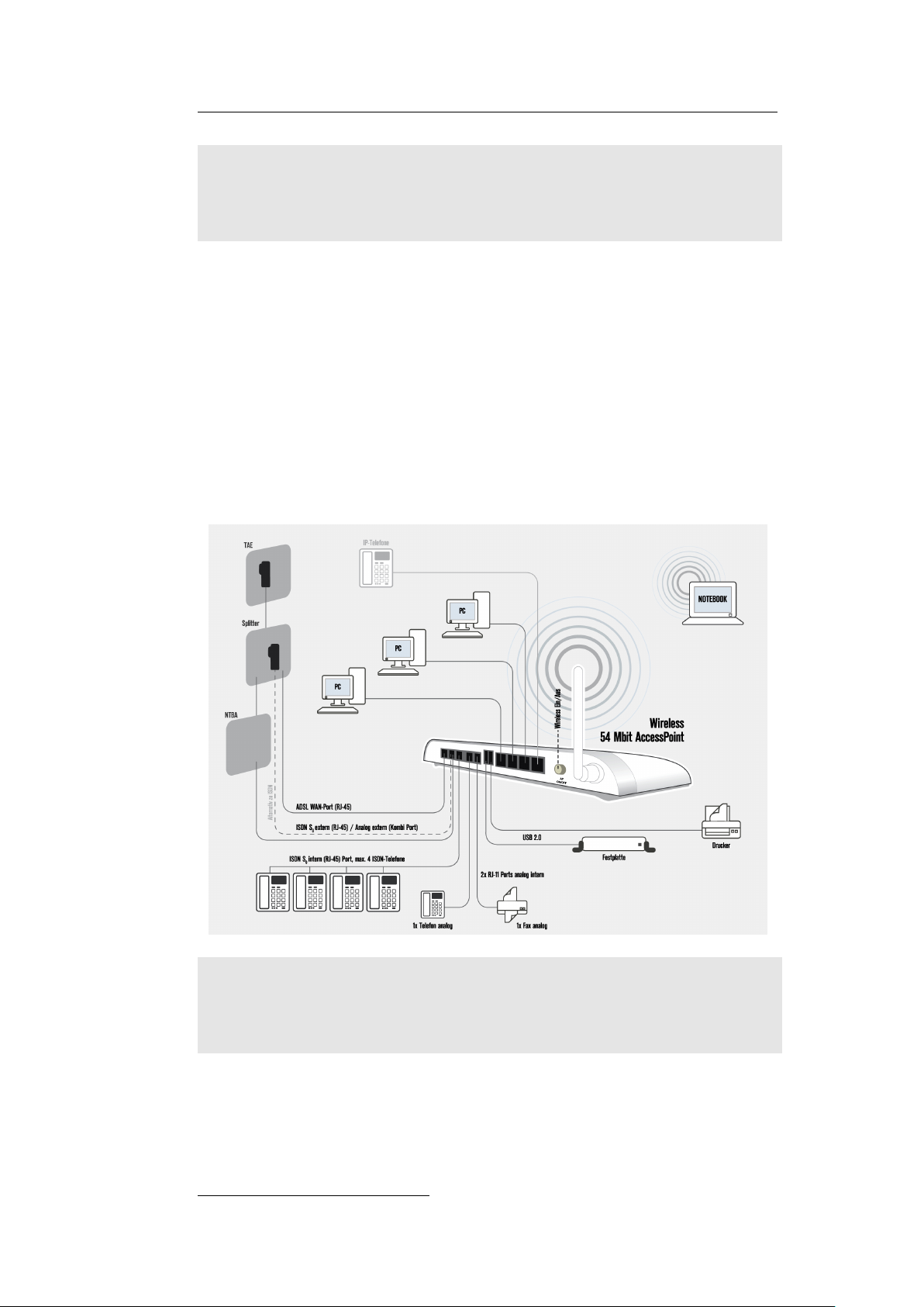
1.4.4 Example
Note:
Analog line: Please connect analog line to port “a/b” on
the HorstBox.
ISDN line: Please connect ISDN line to NTBA2and NTBA
to port “S0 Ext” on the HorstBox.
2
Connecting the ISDN line to NTBA is mandatory!
Page 18

2 Getting Started
Before you install the HorstBox, check to see whether a network
is installed and configured. If necessary, install and configure a
network according to the documentation of the operating system
of your computer.
2.1 Shipment
HorstBox DVA-G3342SD
- Power adaptor: 230V (Output: 12V, 1,5A)
- TAE adaptor, universal coded - ADSL cable (RJ45), gray
- Phone cable (RJ45 to TAE), black - ISDN cable (RJ45), red
- CAT-5 Network cable, blue - ISDN cable (RJ45), black
- WLAN antenna, screwable
1
- Wall bracket
- Installation guide - CD-ROM
- Adaptor: RJ11 plug to 3 TAE ports (NNF) for analog devices
Table 2.1: Shipment
Please contact your sales person immediately, if parts are missing
or broken.
Note:
1
To extend the range of the WLAN you may want to connect a different
According to the terms of guarantee the HorstBox must be
operated only with the power adaptor provided. Elsewise
the guarantee becomes void.
WLAN antenna, e.g. D-Link ANT24-0700 oder D-Link ANT24-0501, to
the HorstBox.
Page 19
2.2 Description 19
2.2 Description
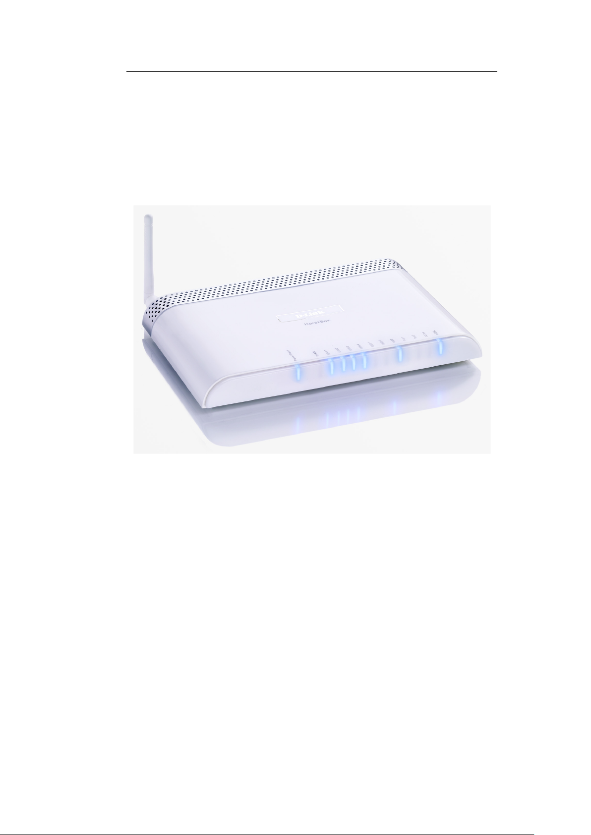
2.2.1 Front Panel
On the front panel of the HorstBox you will find LEDs, which
inform about the status of the device and its ports.
Figure 2.1: Front panel
Page 20

2.2 Description 20
Name LED Function
Power/Status Power/Status
Off Power: no
Red Power: yes; Internet: no
Blue Power: yes; Internet: yes
WLAN Communication over WLAN
Off Access Point: switched off
Blue Access Point: switched on
Blue & blinking Data activity
LAN 1-4 Communication over LAN 1-4
Off Netwerk connection: no
Blue Netwerk connection: yes
Blue & blinking Data activity
USB 1, USB 2
Off Device connected: no
Blue Device connected: yes
VoIP Communication on VoIP connection
Off Connected to VoIP server: no
Blue VoIP account registered or online
Blue & blinking Connected to VoIP server: connecting
Tel 1-2 Analog phone
Off Activity: no
Blue Activity: via land line
Blue & blinking Activity: via VoIP
S0int Communication on internal S0-Bus
Off Activity: no
Blue Activity: via land line
Blue & blinking slow: ca. 2x per second
Activity: via VoIP
Blue & blinking quick: ca. 4x per second
Activity: via analog or ISDN phone and VoIP
ADSL Communication over ADSL
Blue DSL connection: yes
Blue & blinking slow: ca. 2x per second
DSL connection: no
Blue & blinking quick: ca. 4x per second
DSL connection: synchronising
Blue & blinking erratic: Data communication
Table 2.2: Front panel: Functions of LEDs
Page 21
2.2 Description 21
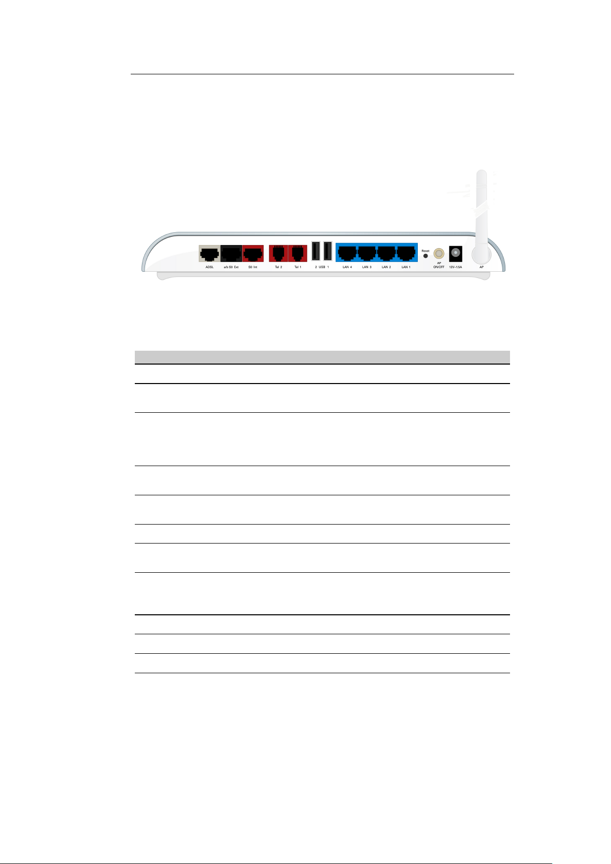
2.2.2 Back Panel
The back panel houses all ports of the HorstBox and the WLAN
and Reset switches.
Figure 2.2: Back panel
Name Port type, Color Function
Order from left to right
ADSL WAN port, (RJ45), gray connect to DSL port on
a/b S0Ext Combi port, (RJ45), black connect to ISDN port on
S0Int ISDN port, (RJ45), red connect ISDN devices to
Tel 2, Tel 1 Phone ports, (RJ11), red Connect up to two analog
USB 2, USB 1 USB ports Connect USB devices
LAN 4 - 1 Ethernet ports, (RJ45), blue Connect up to four ether-
Reset Reset switch To restart press switch for
For a factory reset press switch and hold for ca. 10 second
AP ON/OFF WLAN switch Switch WLAN on and off
12V˜1,5A Power port (round) Connect to power supply
AP Antenna port (round, RP-SMA) Connect WLAN antenna
Table 2.3: Back panel: Colors and functions of ports
splitter
splitter or analog port
(for analog lines use the
adaptor)
internal S0-Bus
phones
net devices
ca. 1 second
Page 22

2.3 Installation 22
2.3 Installation
Please read chapter 1.2 Installation Considerations on p.13 before
installing the HorstBox.
2.3.1 Preparations
Before configuring the HorstBox prepare the device as described
in this section.
• Install the HorstBox at the desired location.
• Provide for air circulation. Do not cover the HorstBox.
•
Connect the HorstBox to your computer. Use the blue network cable provided. Plug it into one of the blue ports of
the device. Plug the other end into the port of the network
adapter card (NIC) of your computer.
•
Plug the power adaptor plug into the power port of the
HorstBox.
•
Plug the power plug of the power adaptor into a socket. This
will make the HorstBox boot up.
•
Boot up the computer you want to use for configuring the
HorstBox.
All preparations are done now. You can start to configure the
HorstBox after the LED reports readiness of the device. These
LEDs should be “on” by now:
assumed that the computer connected to a LAN port is ready,
too.
Note:
The default IP address of the HorstBox is
Make sure that your network is working in the same segment
(192.168.0.x).
If you plan to integrate the HorstBox into an existing
network, you may want to disable the DHCP server temporarily as the HorstBox provides another DHCP server
as default. Using two DHCP servers uncontrolled in one
network may cause severe problems.
Power,Stat
and at least 1x
http://horstbox
LAN
,
.
Page 23

2.3 Installation 23
An easy way to configure the HorstBox is to connect a computer
directly and let it get an IP address from the DHCP server of the
HorstBox. Start the HorstBox first, the computer second.
2.3.2 Connect to the HorstBox
The HorstBox can be configured via a WLAN connection or via a
LAN connection using an ethernet cable.
WLAN Connection
Setting up a WLAN requires a WLAN adaptor installed on your
computer, eg. DWL-G630 (PCMCIA), DWL-G122 (USB) or DWLG510 (PCI).
This section describes the setup of a WLAN for Windows XP.
For other operating systems please refer to the documentation
provided. You may find additional information on the web-sites
of the software manufacturer.
The procedure may differ, if the WLAN adaptor comes with its
own setup program. Please refer to the documentation delivered or configure the program to use the Windows configuration
procedure.
On the desktop right click on the Symbol
context menu choose PROPE R TIES.
In the dialog
icon
WI RELESS NETWORK CONNEC TIONS
choose SHOW WIRELESS NETWORKS.
Mark the entry
enter the network key as asked. The HorstBox uses WPA-PSK for
encryption.
You will find the network key on a sticker on the bottom of the
device.
Enter the network key into both fields and click on CONNE CT.
NE TWORK CONNEC TIONS
dlink
and click on
CO NNECT
NE TWORK
click right click on the
. From the context menu
. In the next dialog
. From the
Page 24
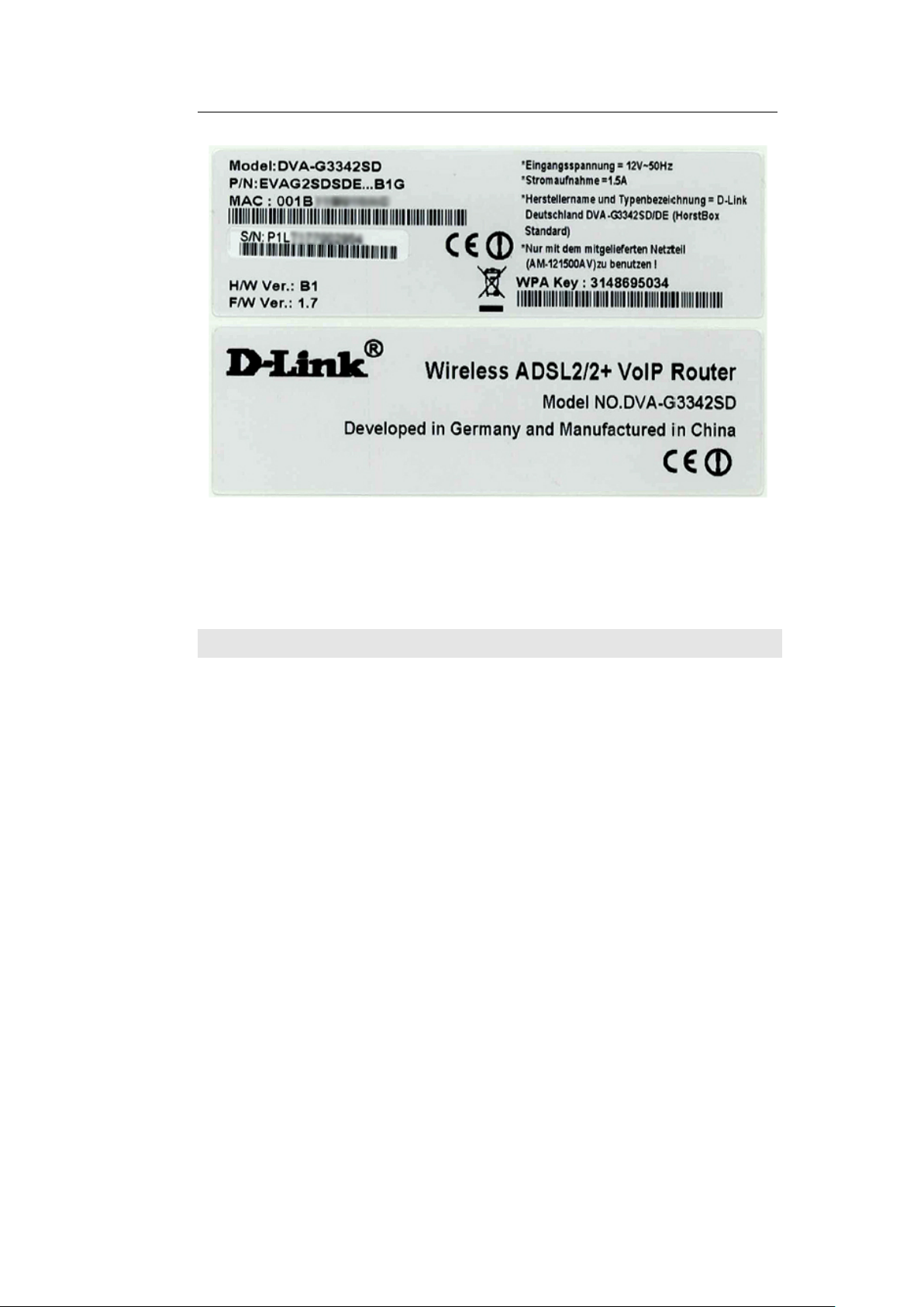
2.3 Installation 24
Figure 2.3: Sticker with Network Key
The dialog
WI RELESS NETW ORK CONNECTI ONS
now shows the
connection to network dlink.
Note: For security reasons change the WPA-PSK key at once.
The status tray will show a symbol for the wireless connection.
LAN Connection
To connect the HorstBox to your computer, use the blue ethernet
cable delivered. Put one end into one of the blue ports on the
HorstBox, the other end into the ethernet port of your computer.
Page 25
2.3 Installation 25
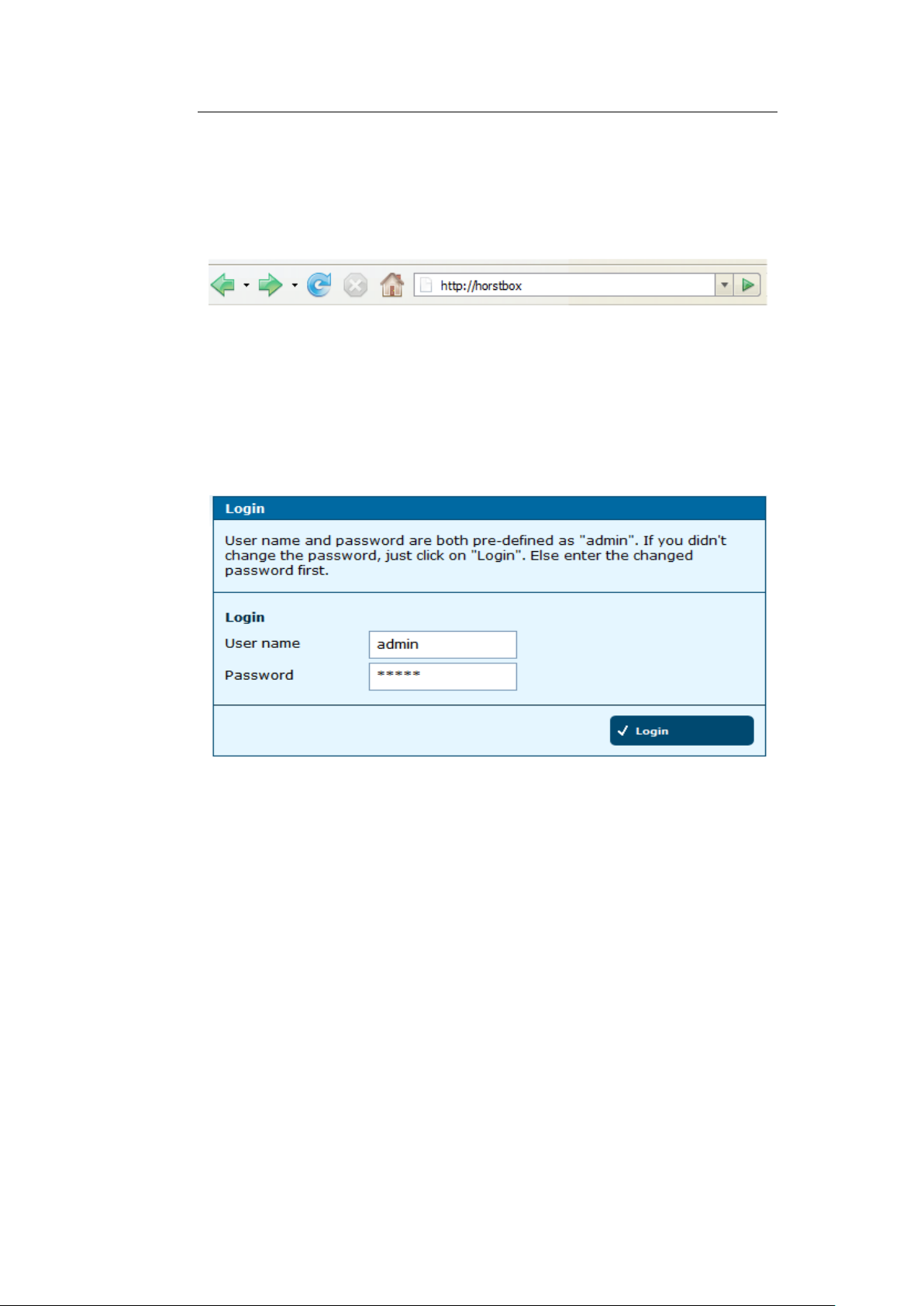
2.3.3 Configuration
To configure the HorstBox via its graphic user interface, call up
the URL http://horstbox in a browser.
Figure 2.4: Enter address in browser
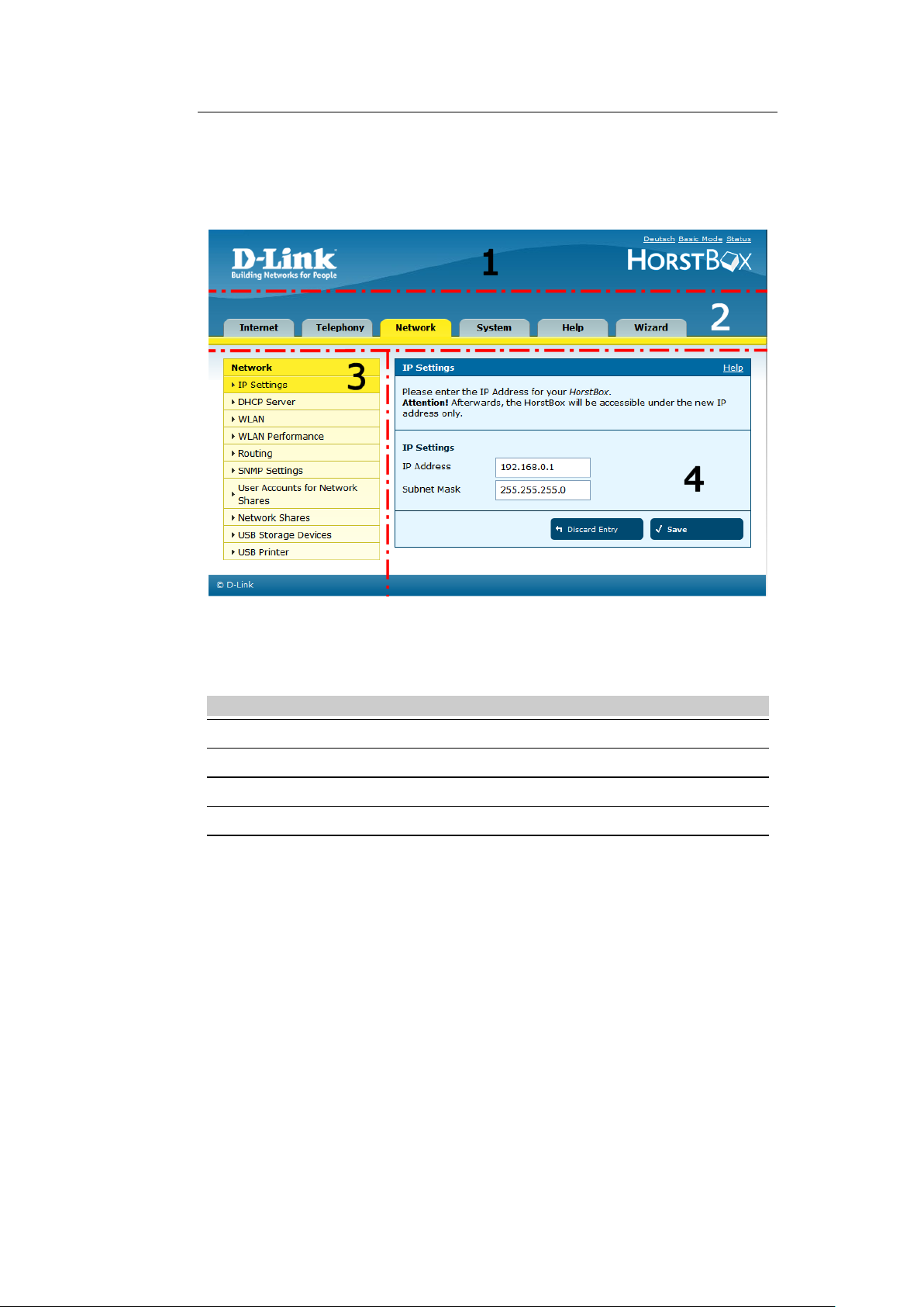
Username and Password are pre-defined as admin. If you didn’t
change the password, just click on
HorstBox.: admin / default password: admin.
Else enter the changed password first. Click on LOGIN.
LO GIN
to get access the
Figure 2.5: User name and Password
If you do the first configuration best use the wizard, which will
start automatically in the browser.
The wizard guides you through all important settings and within
minutes the HorstBox is up and running.
To change settings or install phones later, call up the URL
http://horstbox
dress of the HorstBox, start the graphical user interface by entering the new IP address into the browser.
The graphical user interface shows up in the browser. It is
structured by several tabs, one for each area of functionality.
again. If you have changed the default IP ad-
Page 26
2.3 Installation 26
You can switch between basic and expert mode. While the expert
mode provides more detailed settings, for most users the settings
made in basic mode will be sufficient.
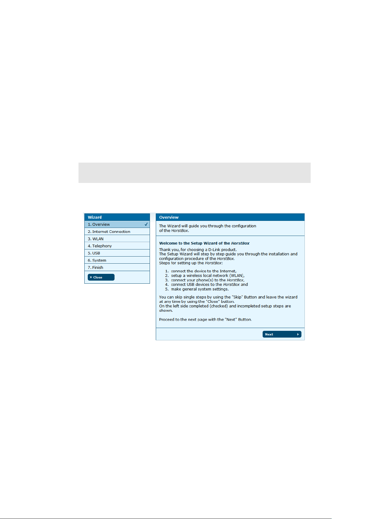
Figure 2.6: Graphical user interface
No Name Function
1 Switch Switch language and modes; status report
2 Tab Open a new tab by clicking on it
3 Navigation column Open new page inside a tab for more settings
4 Text Information / settings / online help
Table 2.4: Graphical User Interface: Functions
Page 27
3 Wizard
The Wizard will guide you step-by-step through the installation
and configuration of the HorstBox. Within minutes the HorstBox
will be ready to go.
Note:
To start the wizard click on
Alternatively start the wizard via the tab WIZ ARD.
For security reasons configure the HorstBox via a network
cable only. Do not use a WLAN connection.
ST AR T WI ZARD
on the start page.
Figure 3.1: Overview Wizard
On the left side of the screen all steps are shown. Those already
finished are ticked off. Clicking on
Wizard with no settings saved.
CL OSE
will terminate the
Page 28
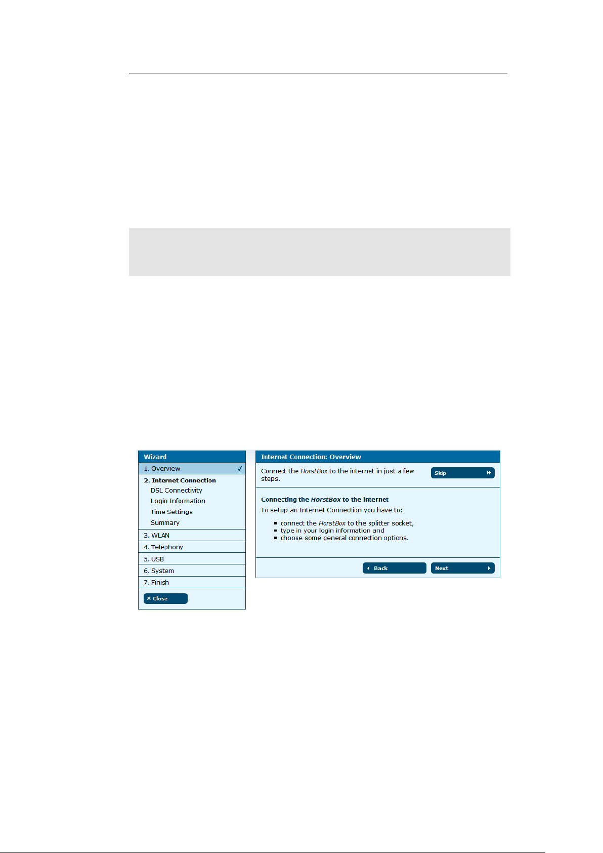
3.1 Internet Connection 28
The configuration of the HorstBox is arranged in five main steps:
1. connect the device to the Internet,
2. setup a wireless local network (WLAN),
3. connect your phone(s) to the HorstBox,
4. connect USB devices to the HorstBox and
5. make general system settings.
Note:
This section will explain all configuration steps. If you do not
want e.g. to connect an analog phone, just skip that step. To
open the next page, click on NEXT.
All user names, phone numbers or passwords used in
this manual are examples only.
Please make sure to use your own data only!
3.1 Internet Connection
Here you will set up the Internet connection of the HorstBox.
Connect the device to the DSL socket, enter all necessary login
details and choose some general connectivity options.
Figure 3.2: Internet connection: Overview
The overview shows all steps required to set up the Internet
connection.
Page 29
3.1 Internet Connection 29
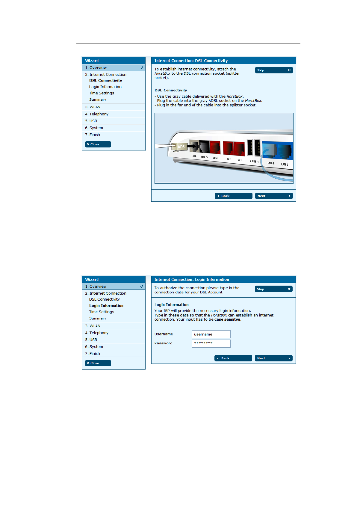
Figure 3.3: Internet connection: DSL connectivity
Use the gray network cable delivered with the HorstBox. Put one
end into the DSL port (gray), the other end into the DSL port on
the splitter.
Click on NEXT, to open the next page to enter the login details.
Figure 3.4: Internet connection: Login details
Your Internet Service Provider (ISP) will provide your login details.
Page 30
3.1 Internet Connection 30
Enter User name and Password for the HorstBox to store and
to establish an Internet connection. Your input has to be case
sensitve.
Click on NEXT, to open the page for the time settings.
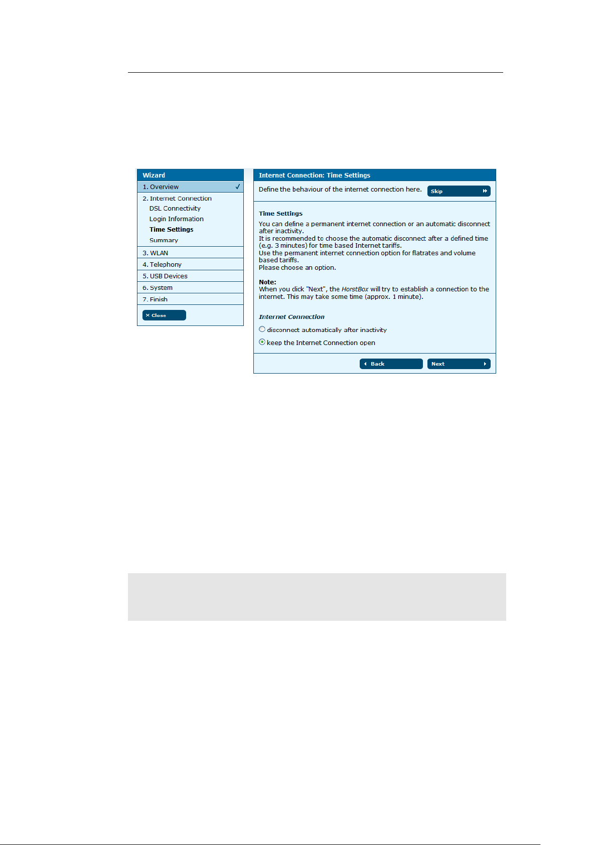
Figure 3.5: Internet connection: Time Settings
You can define a permanent Internet connection or an automatic
disconnection after inactivity.
It is recommended to choose the automatic disconnect after a
defined time (e.g. 3 minutes) for time based Internet tariffs.
Use the permanent Internet connection option for flatrates and
volume based tariffs.
You can change these settings later on the tab
IN TERNET
, page
DSL ACCESS.
Choose an option.
Note:
If you choose automatic disconnect after certain period of
inactivity, the connection will be terminated. No VoIP calls
will go through until a new connection is established.
Click on
NE XT
, to open the summary page for the Internet con-
nection settings.
Click on NEXT to set up the WLAN in just three simple steps.
Page 31

3.2 WLAN 31
Figure 3.6: Internet connection: Summary
3.2 WLAN
Here you will prepare the HorstBox for the WLAN. Attach the
antenna to the device, enter a name for your wireless network
and choose some simple security options.
Figure 3.7: WLAN: Overview
Click on NEXT to get instructions on how to attach the antenna.
Page 32

3.2 WLAN 32
Figure 3.8: WLAN: Attaching the antenna
Plugin the antenna into the antenna socket and screw on clock-
wise. Flip the antenna into an upright position.
Click on
WLAN.
NE XT
, to open the page to specify a name (SSID) for your
Figure 3.9: WLAN: Name (SSID)
Page 33

3.2 WLAN 33
Enter a unique name for your WLAN in order to identify and
propagate it wireless.
Click on NEXT, to open the page for the security settings.
Note: Without any security your WLAN will be open for everyone!
Figure 3.10: WLAN: Security settings
Choose a encryption method and a strong password for the communication with and within your WLAN.
Note:
Use at least WEP as security standard, better WPA. Check
whether all WLAN devices are able to handle WPA.
Page 34

3.2 WLAN 34
Click on
NE XT
, to open the summary page for the WLAN settings.
Figure 3.11: WLAN: Summary
If you used the WLAN switch to switch off the WLAN, a red
framed warning will appear. You may continue using the wizard.
All WLAN settings will become effective once the WLAN is switched
on manually.
If the WLAN is switched off (WLAN switch on the backpanel), a
red framed warning is shown. Continue with the wizard. All
WLAN settings became active, the next time you switch on the
WLAN.
Figure 3.12: Message WLAN switched off
Click on
NE XT
to configure the HorstBox as a PBX in just four
steps.
Page 35

3.3 Telephony 35
3.3 Telephony
To use the HorstBox as phone system PBX you must at least
connect one phone (analog or ISDN). Configure the HorstBox and
do a functional test. You may set up a VoIP account here as well.
Figure 3.13: Telephony: Overview
Click on NEXT to learn how to connect an analog phone.
Connect an analog phone to one of the analog ports (red) “Tel 1”
or “Tel 2” on the HorstBox. Use the adaptor provided (left port,
f-coded) and the cable of your telephone.
Figure 3.14: Telephony: Connect an analog phone
Page 36

3.3 Telephony 36
Click on NEXT.
Figure 3.15: Telephony: Name the analog phone
Please choose unique phone names so the further administration
of the HorstBox will become more comfortable.
Click on NEXT to open the functional test page.
Figure 3.16: Telephony: Functional test
Page 37

3.3 Telephony 37
The functional test checks whether the phone is properly con-
nected. The HorstBox sends a signal and the phone should ring.
Pick up the receiver and put it back into the craddle.
Click on NEXT to continue.
Figure 3.17: Telephony: Second analog phone
If desired, you may connect and set up a second analog phone.
Use the red telephone cable provided. Please repeat the steps
described above. Else skip this step.
Page 38

3.3 Telephony 38
Now you can connect and set up an ISDN phone. Connect the
phone to the port “S0Int” on the HorstBox. Use the red phone
cable (ISDN) provided.
Click on NEXT.
Figure 3.19: Telephony: Name the ISDN phone
Figure 3.18: Telephony: ISDN Phone
Please choose unique phone names so the further administration
of the HorstBox will become more comfortable.
Page 39

3.3 Telephony 39
Click on NEXT to open the functional test page.
Figure 3.20: Telephony: Functional test
The functional test checks whether the phone is properly con-
nected. The HorstBox sends a signal and the phone should ring.
Pick up the receiver and put it back into the craddle.
Before executing the functional test you have to set up your ISDN
phone to MSN 21. Please refer to the documentation of the phone
to learn how to to do this.
You can configure more ISDN phones later on the tab
TE LEPHONY
on the page PHONE S AND DEVI CES.
Click on NEXT to continue.
Page 40

3.3 Telephony 40
Now you will set up the external phone line.
Figure 3.21: Telephony: External phone line
Connect the HorstBox to the phone line.
Analog main line:
Connect the black analog cable to the black
connector "‘a/b S0 Ext"’ at your HorstBox. Connect the other end
to the corresponding jack at the DSL splitter.
ISDN main line:
Connect the black ISDN cable to the black connector "‘a/b S0 Ext"’. Connect the other end to the corresponding
connector at the NTBA.
Note: Attention! ISDN lines require connecting to an NTBA.
Page 41

3.3 Telephony 41
Afterwards you have to choose one of the options:
the analog line (see left Fig.)
or
I want to use the ISDN line (see
right Fig.).
Click on NEXT, to enter the phone numbers.
Figure 3.22: Telephony: Phone numbers
I want to use
Enter the phone number(s). Use the first ISDN phone number
respectively the analog phone number as default number. The
HorstBox will use the number to handle outgoing calls. This
number will be displayed as "‘Caller ID"’.
Click on NEXT.
Figure 3.23: Telephony: VoIP
Page 42

3.3 Telephony 42
Before you can use Internet telephony you have to register with a
VoIP provider, e.g. SipGate to receive a VoIP phone number.
In the next step please enter your login details for the VoIP account in order to make phone calls over the Internet.
Click on NEXT.
Figure 3.24: Telephony: VoIP login details
Enter host name or IP address of the VoIP server into the field
SE RVER
, the VoIP number into the field
PH ONE NUMBER
, user
name and password of the VoIP account into the appropriate
fields.
Click on NEXT for the summary of the telephony settings.
Figure 3.25: Telephony: Summary
Click again on NEXT to set up the USB devices.
Page 43

3.4 USB 43
3.4 USB
Figure 3.26: USB: Overview
Click on
list Share (guest account) choose an option.
Click on NEXT to set up the printer shares.
NE XT
to set up the storage shares. From the drop-down
Figure 3.27: USB: Storage Shares
Page 44

3.4 USB 44
Figure 3.28: USB: Printer Shares
Select the printer you want to share in your LAN. Only one printer
may be shared at a time.
Click on NEXT for the summary page of the USB devices.
Figure 3.29: USB: Summary
Click again on NEXT for the system settings.
Page 45

3.5 System 45
3.5 System
Only some more settings are required now:
1.
System Time. To make sure that rules and tasks can be
executed at the right time you have to set up the system
time properly.
2.
Password. To protect the HorstBox against unauthorized or
illegal access you have to enter an Administration Password.
[Default user: admin; default password: admin.]
Figure 3.30: System: Overview
Click on NEXT to set up the time of the HorstBox.
Figure 3.31: System: Time Settings
Let the HorstBox regulate the system time via Network Time
Protocl (NTP) automatically or synchronize the system time with
your computer’s time.
Page 46

3.5 System 46
Note: It’s recommended to use the “automatic” option.
To set the time manually, use the page TIME on the tab SYS TEM.
Choose one option and click on
NE XT
to set up the password
protection.
A password protects against unauthorized or illegal access.
Change the default password: admin at once!
Figure 3.32: System: Password Protection
Click on NEXT.
You may have to re-login with user name
admin
and the new
password.
Click on NEXT for the summary of the system settings.
Figure 3.33: System: Summary
Click on NEXT for the last page of the wizard.
Page 47

3.5 System 47
Figure 3.34: Wizard: Finish
Congratulation! Your HorstBox has been setup successfully
and is now ready for use.
You have completed all settings now. To finish the Wizard and to
save all settings, click on NEXT on the Finish page.
To go back to a previous step please use BACK.
To close the Wizard click on
PAGE (see next page)s will be shown.
CL OSE
(on the left). The
ST ATUS
For further questions, additional information and help, please
take a look at the user manual and the online help.
On the status page all important information of your HorstBox
(Internet, Telephony, Network and System) can be viewed at a
glance.
Page 48

3.5 System 48
Note:
Figure 3.35: Status page
To call up the status page, use the link
corner) or just click on the D-Link logo.
ST ATUS
(top right
Page 49

4 Telephony
This chapter introduces all telephony settings.
Additionally you may need:
• Phone numbers/external MSNs
as provided by your telephone service provider.
• Manuals for your phone(s)
To navigate in the tab TELEPHO NY use the navigation column.
Figure 4.1: Navigation column Telephony
Note: To stay online permanently use a flatrate!
Page 50

4.1 Lines and Accounts 50
4.1 Lines and Accounts
4.1.1 Main Telephone Line
Before you configure the accounts choose the main telephone
line: analog or ISDN. Select the desired entry in the drop down
list Line Type and click on SAVE.
Figure 4.2: Lines and Accounts
In-bound and out-bound connections are established over ac-
counts. Here you can set up accounts for different kinds of lines.
You can set up one analog account only and up to 10 ISDN and
10 VoIP accounts respectively.
The HorstBox’s lifeline support provides access to an analog
line via an analog phone in times of electrical power outage.
Page 51

4.1 Lines and Accounts 51
On the tab
or devices.
You can use rules (see tabs
preselect which account will use what phone and when).
PH ONES AN D DEVIC ES
CA LL RU LES
you will link accounts to phones
and
DI AL RU LES
4.1.2 Edit Analog Account
To edit the analog account, first select
bottom part of the screen click on
set up as default. This will change if you change the line type.
Analog
ED IT
. The analog account is
as line type. In the
to
Figure 4.3: Edit Analog Account
Enter a name for the account and the phone number. Please
choose unique account names so the further administration of
the HorstBox will become more comfortable.
Calling Line Identification Restriction (CLIR) is a feature which
may be provided by your phone service provider. The common
term for preventing the display of a calling number is blocking.
Page 52

4.1 Lines and Accounts 52
You may block your caller ID by choosing the option
Blocking
the next call dial
To unblock your caller ID, simply press
. Enter a prefix, e.g.
e*e3e1e
# as prefix before the phone number.
e*e3e1e
#
. To block your caller ID for
e#e3e1e
#
Caller ID
<Your phone
number>.
For emergency calls your phone number will not be blocked,
independent whether you have activated or deactivate Caller ID
Blocking.
To save the settings, click on SAVE.
Saving successfully is reported in a success message (green
frame).
If an error occurs you will see an error message (red frame).
Change the settings in the box with the red frame and again click
on SAVE.
To cancel the dialog, click on CANCEL. The previous page will be
displayed.
4.1.3 Delete Analog Account
There is no need to delete the analog account. Simply select
as line type and click on SAVE.
The analog account will not be used any longer. Changing the
line type changes the default account too.
ISDN
4.1.4 Assign ISDN Account
To assign an ISDN account, choose
bottom part of the screen click on ASSIGN.
On the page
ISDN ACCOU NT - ADD
ISDN account and the phone number (MSN).
ISDN
as line type. At the
enter an unique name for the
Page 53

4.1 Lines and Accounts 53
Call Transfers as ISDN Service
You may set up some ISDN services as options. These ISDN
services may be offered by your telephone service provider. The
HorstBox will help you to configure the service, but the functions
will be allocate at the switchboard.
• Permanent call forwarding
bound calls to this phone number (MSN) will be transfered to
the phone number entered in the field
• Call forwarding on no reply
bound calls to this phone number (MSN) will be transfered
to the phone number entered in the field
reply.
• Call forwarding on line busy
in-bound calls to this phone number (MSN) will be transfered
to the phone number entered in the field
line is busy.
Example
Phone number (MSN) 135790 should be transferred permanently
to phone number 246813.
After you have entered the values accordingly, click on
HorstBox will now send the information to the switchboard. All
in-bound calls to 135790 are rerouted to 246813 now.
: Activate this option and all in-
NU MBER
: Activate this option and all in-
: Activate this option and all
NU MBER
permanently.
NU MBER
when the
SAV E
on no
. The
The HorstBox will no longer answer to 135790, until the perma-
nent transfer is cancelled.
To deactive the call transfers, deactivate the option accordingly
and click on
to the switrchboard. The call transfers are reset. All in-bound
calls to 135790 are answered by the HorstBox.
Note: Using call transfer options may cause additional costs!
To save the new account, click on SAVE.
SAV E
. Again the HorstBox will send the information
Page 54

4.1 Lines and Accounts 54
Figure 4.4: Add ISDN Account
Saving successfully is reported in a success message (green
frame).
If an error occurs you will see an error message (red frame).
Change the settings in the box with the red frame and again click
on SAVE.
To cancel the dialog, click on CANCEL. The previous page will be
displayed.
Page 55

4.1 Lines and Accounts 55
4.1.5 Edit ISDN Account
To edit an ISDN account click on
adding an account opens, but this time all fields contain values.
Edit the values and click on SAVE.
Figure 4.5: Edit ISDN Account
ED IT
. The same dialog as for
4.1.6 Delete ISDN Account
To delete an ISDN account click on
by again clicking on
page LINES AND ACCOU NTS will open and display a message.
DE LETE
. The account will be deleted and the
DE LETE
. Confirm the warning
4.1.7 Assign VoIP Account
Before you can use Internet telephony you have to register with a
VoIP provider, e.g. SipGate to receive a VoIP phone number.
To assign a VoIP account, click on ASSIGN.
Enter host name or IP address of the VoIP server into the field
SE RVER
User name and Password into the appropriate fields.
To save the settings, click on SAVE.
Saving successfully is reported in a success message (green
frame).
, the VoIP phone number into the field
PH ONE NUMBER
,
Page 56

4.1 Lines and Accounts 56
If an error occurs you will see an error message (red frame).
Change the settings in the box with the red frame and again click
on SAVE.
To cancel the dialog, click on CANCEL. The previous page will be
displayed.
Note: While using VoIP stay online permanently and use a flat-
rate!
If the option
(see
IN TERNET
disconnect automatically after inactivity
, page
DSL ACCESS
), in-bound calls are no longer
is activated
possible, once the connection is terminated. Out-bound calls
need to establish a connection to the Internet first.
Page 57

4.1 Lines and Accounts 57
Figure 4.6: Assign VoIP Account
4.1.8 Edit VoIP Account
To edit a VoIP account click on
adding an account opens, but this time all fields contain values.
Edit the values and click on SAVE.
ED IT
. The same dialog as for
4.1.9 Delete VoIP Account
To delete a VoIP account, click on
by again clicking on
page LINES AND ACCOU NTS will open and display a message.
DE LETE
. The account will be deleted and the
DE LETE
. Confirm the warning
Page 58

4.2 Phones and Devices 58
4.2 Phones and Devices
Register the connected phones with the HorstBox. You can set
up external call diversions. For each connected device Dial and
Call rules can be defined.
You may connect up to 2 analog devices and up to 4 ISDN devices.
The HorstBox comes with some devices preconfigured. Adjust
those devices to your needs. You may also administrate up to 10
MSNs.
For internal calls (i.e. from one of your phone to another) dial
e*e
(double asterisk) as a prefix. For outgoing calls simply dial the
phone number.
*
Figure 4.7: Phones and Devices
Page 59

4.2 Phones and Devices 59
4.2.1 Default and Fallback account
The Default account will be used for out-bound calls.
The Fallback account will be used for out-bound calls, if the
default account is now available. Therefor use different account
types (analog, ISDN or VoIP) for default and fallback account.
4.2.2 Comfort Options
The HorstBox offer a variety of comfort options for phones and
devices.
• Call Through (ISDN only):
Enter a phone number (MSN) for
an ISDN phone, which will receive in-bound calls without
further configuration.
• Do not disturb:
longer. Out-bound calls are still possible. Select
Once activated, the telephone will ring no
Always
or specify a period of time. This may be helpful as a night
switch. Enter the time in 5 minute intervals.
Use the key combinations:
e#e2e6e
# to deactivate.
• Block caller identification:
not be transmitted.
• Allow call waiting:
1
A second in-bound call will be signaled
e*e2e6e
#
to activate the option and
(CLIR) Your phone number will
during a ongoing call.
• Call forwarding
Permanent call forwarding:
Activate this option and all inbound calls to this phone number (MSN) will be transfered to
the phone number entered in the field
NU MBER
permanently.
Call forwarding on no reply:
Activate this option and all inbound calls to this phone number (MSN) will be transfered
to the phone number entered in the field
NU MBER
on no
reply.
1
For emergency calls your phone number will not be blocked, independent
whether you have activated or deactivated Caller ID Blocking.
Page 60

4.2 Phones and Devices 60
Call forwarding on line busy:
in-bound calls to this phone number (MSN) will be transfered
to the phone number entered in the field
line is busy.
Activate this option and all
NU MBER
when the
Figure 4.8: Comfort options
Page 61

4.2 Phones and Devices 61
Black- and White Listing
Manage in- and out-bound calls via Black or White Listing.
Figure 4.9: Black and White Listing
A “black list” will suppress all phone numbers entered. In-bound
calls to these numbers will be rejected, while out-bound calls to
any of the numbers entered will be blocked.
A “white list” does allow calls to the numbers entered only. For
any other number, in-bound calls will be rejected, while outbound calls will be blocked respectively.
Page 62

4.2 Phones and Devices 62
Add Black or White Listing
To add black or white listing for incoming or out-bound calls,
choose the appropriate optin form one of the drop-down lists
Functionality, and click on ADD.
You may edit black or white lists.
Figure 4.10: Add Black/White Listing
Enter the phone number and click on ASSIG N.
Delete Black or White Listing
To delete a black or white list, click on
DE LETE
warning by again clicking on DE LETE
. Confirm the
Page 63

4.2 Phones and Devices 63
4.2.3 Edit Analog Device
The HorstBox allows for up to two analog devices to be connected.
Both devices are already configured. Adjust those settings to your
needs.
Figure 4.11: Edit Analog Device
To edit an analog device click on EDIT.
In the field NAME enter an unique name for the phone.
A phone connected to port “Tel 1” will answer to phone number
11, connected to port “Tel 2” to number 12. The internal phone
number can not be changed.
Page 64

4.2 Phones and Devices 64
For internal calls dial
e
2
to call the second analog phone. For outgoing call simply dial
e*e
* (double asterisk) as a prefix, e.g.e*e*e1
the phone number.
Choose the default account and the Fallback account.
Choose one or more comfort options, see 4.2.2 Comfort Options
on p.59.
To save the settings, click on SAVE.
Saving successfully is reported in a success message (green
frame).
If an error occurs you will see an error message (red frame).
Change the settings in the box with the red frame and again click
on SAVE.
To cancel the dialog, click on CANCEL. The previous page will be
displayed.
4.2.4 Delete Analog Device
The analog devices can not be deleted. Remove the cables if
neccessary.
Page 65

4.2 Phones and Devices 65
4.2.5 Edit ISDN Device
The HorstBox allows for up to four ISDN devices to be connected.
All four devices are already configured. Adjust those settings to
your needs. Use an ISDN hub, if you need to connect more than
one ISDN device.
To edit the settings of an ISDN device click on EDIT.
In the field NAME enter an unique name for the phone.
For internal calls dial
e2e
2
to call the MSN 21. You may configure several ISDN devices
e*e
*
(double asterisk) as a prefix, e.g.
e*e
to answer to the same MSN. For outgoing calls simply dial the
phone number.
Choose the default account and the fallback account.
Choose one or more comfort options, see 4.2.2 Comfort Options
on p.59.
To save the settings, click on SAVE.
Saving successfully is reported in a success message (green
frame).
If an error occurs you will see an error message (red frame).
Change the settings in the box with the red frame and again click
on SAVE.
To cancel the dialog, click on CANCEL. The previous page will be
displayed.
*
4.2.6 Configure ISDN Device
Next you have to configure your ISDN device(s) to answer to
an internal MSN, as set up before. Please refer to the devices
documentation.
One ISDN device may answer to several MSN and two devices
may answer to the same MSN.
Page 66

4.2 Phones and Devices 66
Figure 4.12: Edit ISDN Device
4.2.7 Delete ISDN Device
The ISDN devices can not be deleted. Remove the cable if necces-
sary.
Page 67

4.3 Call Rules 67
4.3 Call Rules
Call Rules manage the handling of in-bound calls. For each
account you can define which phone is supposed to ring. Of
course several devices may signal an in-bound call in parallel.
To use Call Rules you have to set up at least one account (see
section 4.1 Lines and Accounts on p.50) and register one device
(see section 4.2 Phones and Devices on p.58).
Figure 4.13: Call Rules
4.3.1 Edit Call Rule
To edit a call rule choose its account and click on
Change the options.
On the page
and devices are listed.
Choose the phones and devices that should ring for the in-bound
call. Of course several devices may signal an in-bound call in
parallel.
To answer an in-bound call on a non-active phone, pick up the
receiver and dial
To save the settings, click on SAVE.
CA LL RUL ES - EDIT CAL L RULE
e*e8e
2 .
all registered phones
ED IT RULE
.
Page 68

4.3 Call Rules 68
Figure 4.14: Edit call rules
To cancel the dialog, click on CANCEL. The previous page will be
displayed.
4.3.2 Delete Call Rule
Call rules cannot be deleted, but you can deactivate all options.
Page 69

4.4 Dial Rules 69
4.4 Dial Rules
Dial Rules can define favorable connections for out-bound calls.
The application of these rules depends on the time of day and
on the prefix number of the number you have dialed (e.g. longdistance-call, local call, cell phone call or VoIP call). Dialing specific digits before the phone number allows Least-Cost-Routing.
Note:
Emergency call numbers will always be connected via the
exchange line.
Figure 4.15: Dial rules
Page 70

4.4 Dial Rules 70
4.4.1 Pre-Defined Emergency Call Dial Rules
Adjust the pre-defined emergency call dial rules to your needs. Always keep these phone number current. Under no circumstances
enter irregular phone numbers. In case of an emergency police,
fire brigade or ambulance cannot be called.
To change the pre-defined dial rules, click on
phone numbers and click on SAVE.
ED IT
, change the
4.4.2 Add Dial Rules
To add dial rules, click on ADD.
Now set up the conditions for the new dial rule.
In the first field
number starting with these numbers will be handled by that rule.
Next set up the time conditions:
time conditions
always The rule is valid continuously.
in this time period
Day of week Choose the day(s) of the week:
PR EFIXES
Set up the time period in 5 minute intervals.
from: hour:minute to: hour:minute
Mon Tue Wed Thu Fri Sat Sun
enter the first numbers. Any phone
Now define the rule. You can
• block
• connect via this account
• connect via this account with amended phone number and
prefix/modifier
To save the new call rule, click on SAVE.
Saving successfully is reported in a success message (green
frame).
If an error occurs you will see an error message (red frame).
Page 71

4.4 Dial Rules 71
Figure 4.16: Add/Edit Dial Rule
Page 72

4.4 Dial Rules 72
Change the settings in the box with the red frame and again click
on SAVE.
To discard all recent entries click on DISCARD EN TR Y.
4.4.3 Edit Dial Rules
To edit a dial rule click on
dial rule opens, but this time all fields contain values. Edit the
values and click on SAVE.
ED IT
. The same dialog as for adding a
4.4.4 Delete Dial Rule
To delete a dial rule click on
again clicking on
page DIAL RULES will open and display a message.
DE LETE
DE LETE
. The dial rule will be deleted and the
. Confirm the warning by
4.4.5 Least Cost Routing/Pre-Selection
For Least Cost Routing (LCR) use the option
number
number.
Note:
. Use either
Make sure that date and time are always adjusted correctly, so the dial rules will be executed at the right time.
Prefix
or
Modifier
with amended phone
to manipulate the phone
Example for calling abroad
1. Define a new dial rule.
2.
Enter the first digits, e.g. the country code, in the field
PR EFIXES (1 in fig. 4.17).
3.
Choose the option
rule to be applied.
4.
Choose the option
"‘ISDN account 2"’.
always
connect
or define the time period for the
and the account to use, e.g.
Page 73

4.4 Dial Rules 73
Figure 4.17: Least Cost Routing/Pre-Selection
5. Activate the option with amended phone number.
6. Leave the field PR EFIXES (2 in fig. 4.17) blank.
7. Enter the phone number of the Call-by-Call provider.
8. To save the new rule, click on SAVE.
All out-bound calls to the certain country will be routed via the
chosen Call-by-Call provider.
Define other dial rules for the weekend, the evenings, or other
area/country codes.
Page 74

4.4 Dial Rules 74
Example for Prefix
Define a new call rule and activate the option
with amended
phone number.
Phone number to call: 01234567890
Enter in field PREFIX ES (1 in fig. 4.17): 01234567890
Leave the field PREFIX ES (2 in fig. 4.17) blank.
Enter in field MODIFI ER (3 in fig. 4.17): 0999
The HorstBox will dial: 099901234567890
Table 4.2: Least Cost Routing: Prefix
To save the new call rule click on SAVE.
Example for Number Modification
Define a new call rule and activate the option
with amended
phone number.
Phone number to call: 01234567890
In the field PREFIX ES (1 in fig. 4.17) enter: 012
In the field PREFIX ES (2 in fig. 4.17) enter: 012
In the field MODIFI ER (3 in fig. 4.17) enter: 0999
The HorstBox will dial: 099934567890
Table 4.3: Least-Cost-Routing: Number modification
To save the new call rule click on SAVE.
You may refine call rules by defining several call rules for different
periods of time and various telephone service providers. The
HorstBox will choose the appropriate call rule, depending on the
day of the week and the current time.
Page 75

4.4 Dial Rules 75
4.4.6 Preselection
You can set up the HorstBox to use a certain telephone service
provider for every out-bound call, differentiate even for calls to
mobile phone numbers or overseacalls.
Define a new call rule and activate the option
phone number.
Example
Always use another account for certain out-bound calls:
1. Define a new dial rule.
2.
Enter the first digits, e.g. the area code, in the field
(1 in fig. 4.17)
3.
Choose the option
rule to be applied.
4.
Choose the option
account 1"’.
5.
Leave the fields
in fig. 4.17) blank.
6. To save the new rule, click on SAVE.
always
connect
PR EFIXES
or define the time period for the
and the account to use, e.g. "‘VoIP
(2 in fig. 4.17) and
with amended
PR EFIXES
MO DIFIER
(3
All out-bound calls starting with the saved digits will be routed
via the chosen account.
Example for Prefix
Define a new call rule and activate the option
phone number.
Phone number to dial: 01234567890
In the field PREFIX ES (1 in fig. 4.17) enter: 012
Leave the field PREFIX ES (2 in fig. 4.17) blank.
In the field MODIFI ER (3 in fig. 4.17) enter: 0999
The HorstBox will dial: 099901234567890
Table 4.4: Preselection: Prefix
with amended
Page 76

4.5 Speed Dialing 76
Example for Number Substitution
Define a new call rule and activate the option
with amended
phone number.
Phone number to dial: 01234567890
In field PREFIX ES (1 in fig. 4.17) enter: 012
In field PREFIX ES (2 in fig. 4.17) enter: 012
In field MODIFI ER (3 in fig. 4.17) enter: 0999
The HorstBox will dial: 099934567890
Table 4.5: Preselection: Number Substitution
To save the new call rule, click on SAVE.
4.5 Speed Dialing
Speed Dialing saves time when calling to certain numbers (up to
99) regularly.
To use Speed Dialing enter
e*e*e
7
as prefix before the speed dialing
number.
Example: Speed Dialing for your bank: 01.
To call your bank, dial
e*e*e7e0e
1 .
4.5.1 Add Speed Dialing
To add a speed dialing number, click on ASSIGN.
In the field
field PHONE NUMBER the phone number.
To save the new speed dialing number, click on SAVE.
If an error occurs you will see an error message (red frame).
SP EED DIALI NG
enter the desired shortcut and in the
Page 77

4.5 Speed Dialing 77
Figure 4.18: Speed Dialing
Change the settings in the box with the red frame and again click
on SAVE.
To cancel the dialog, click on CANCEL. The previous page will be
displayed.
4.5.2 Edit Speed Dialing
To edit a speed dialing number click on
for adding a speed dialing number opens, but this time all fields
contain values. Edit the values and click on SAVE.
ED IT
. The same dialog as
4.5.3 Delete Speed Dialing
To delete a speed dialing number click on
warning by again clicking on
and the page SPEED DIALING will open and display a message.
DE LETE
. The dial rule will be deleted
DE LETE
. Confirm the
Page 78

4.6 Phone Log 78
4.6 Phone Log
The phone log shows an overview over all in-bound and out-bound
calls.
Figure 4.19: Phone Log
4.6.1 Delete Phone Log
To delete the phone log and start a new one, click on DELETE.
4.6.2 Save Phone Log
To save the recent phone log as a file on your computer, click on
SAV E
. Choose the path and directory to store the file and click
on SAVE.
Page 79

4.7 Status 79
4.7 Status
The Phone Status indicates the attached VoIP devices and phones
and assists you with the troubleshooting.
Figure 4.20: Status
Page 80

4.8 QoS 80
4.8 QoS
QoS is short for
with a priority mark may be privileged by routers.
Quality of Service
Figure 4.21: QoS
. Voice data packets flagged
For SIP priority (for VoIP) the range is 0 to 63. The default value
is 6.
For RTP priority (for audio and video streams) the range is 0 to
63. The default value is 11.
Please note! Your ISP must support SIP and RTP priority.
Please use the values for SIP and/or RTP priority provided by
the ISP.
Page 81

4.9 How To Telephone 81
4.9 How To Telephone
Note:
Diverting calls to external numbers may cause additional
costs.
Please refer to the documentation of your phones to find out
which features they support. Sometimes your telephone service
provider has to (de-)activate certain features.
After you have connected and set up all devices to the HorstBox
and added all neccessary (dial or call) rules, you may now use the
phones. Internal calls are free, while external calls may generate
costs.
Most of the known ISDN services will function with the HorstBox
as well, even with analog phones, as long as they provide the
necessary funcions, e.g. a display.
Some of the HorstBox’s PBX funcions can be configured via the
keys of a phone in addition to the graphical user interface (see
overview 4.10 How to control the HorstBox via a phone on p.86
at the end of this chapter).
4.9.1 Answering A Call
You may answer in-bound calls on any registered phone. If due
to call rules a phone does not ring, pick up the receiver and dial
e*e8e
2 .
4.9.2 Internal Calls
You can do internal calls between all registered phones.
For internal calls first press
number (MSN).
The quantity of internal phone numbers depends on how many
devices were registered with the HorstBox.
e*e
*
, then dial the internal phone
Page 82

4.9 How To Telephone 82
Combination Device Port / Internal MSN
e*e*e1e
e*e*e1e
e*e*e2e
Table 4.6:
1 Analog 1 "‘Tel 1"’
2 Analog 2 "‘Tel 2"’
1 –e2e4 ISDN 1 – ISDN 4 MSN 21 – MSN 24
Overview Combination
e*e
*
+phone number for internal
calls
4.9.3 External Calls
Out-bound calls are handled by the default account, unless
dial rules define a different account. To change the account on
demand, press
the current call.
Combinations depend on set up accounts accordingly.
Combination uses account:
e
* and dial the number of the desired account for
e*e1e
1 <No. of account>e# <phone no.> analog or ISDN account
e*e1e
2 <No. of account>e# <phone no.> VoIP account
Table 4.7:
Overview: Combination *-phone number for external
calls
Examples
•
To use the analog account to call phone number
0123456789, dial:
e*e1e1e1e#e0e1e2e3e4e5e6e7e8e
•
To use the second VoIP account to call phone number
0987654321, dial:
e*e1e2e2e#e9e8e7e6e5e4e3e2e
9
1
Page 83

4.9 How To Telephone 83
4.9.4 Speed Dialing
(Numbers to be stored beforehand!)
To use a speed dial or vanity number use
e*e*e
7 as a prefix.
Example
The phone number of your bank is stored as speed dialing number
01. To call your bank just dial:
e*e*e7e0e
1 .
4.9.5 Transfer Calls
•
To transfer a call to another phone number during a call,
press
e
R (aka Hook-Flash).
• Dial the new number and talk to the participant.
•
After you put down the receiver, the first caller will talk to
the new participant
4.9.6 Park A Call on Phones without Park Function
• To park a call during the call press
e
R on the phone, thene2 .
4.9.7 Unpark A Call
• Lift the receiver.
• Press
e
R , thene3 .
4.9.8 Park A Call on Phones with Park Function
•
To park a call during the call press the
phone. Please refer to the manual of your phone to learn
more about this function.
PARK
key on your
Page 84

4.9 How To Telephone 84
4.9.9 Unpark A Call on Phones with Park Function
•
To unpark a call use the menu on your phone. Please refer to
the manual of your phone to learn more about this function.
4.9.10 Telephone Conference with 2 Additional
Callers
Analog Phone
For a telephone conference with two more participants and an
analog phone, proceed as follows:
• Call the first participant.
• During the call press
•
Dial the other phone number and talk to the second partici-
e
R or Hook-Flash.
pant.
• Next dial
e
R again, thene3 .
• You are connected to both parties now.
ISDN Phone
For a telephone conference with two more participants and an
ISDN phone, proceed as follows:
• Call the first participant.
• During the call press the TRA NSFER key.
•
Dial the other phone number and talk to the second participant.
•
Press the
CO NFERENC E
key to start the telephone confer-
ence.
Page 85

4.9 How To Telephone 85
4.9.11 Three-Way Calling (Analog Phone)
•
While talking to participant A you want to talk to participant
B.
•
During the call press
number.
• Participant A is on hold now..
• Talk to participant B.
To end the call you have 3 possibilities:
Hold Second Call, Continue First Call
e
R
(aka Hook-Flash) and dial the phone
To return to A, press
e
R
, then
e
2
. Now B is on hold and you can
talk to A.
Start Telephone conference
To start the telephone conference, press
Finish Second Call, Continue First Call
To finish the second call press
e
R
, then
e
0
. Afterwards you will talk
to participant A again.
4.9.12 Call Waiting (Analog phone)
Answering Call
To answer the new call, press
e
R .
e
R , thene2 .
Reject Call
To reject the new call, press
eRe
0 .
Page 86

4.10 How to control the HorstBox via a phone 86
4.9.13 Do Not Disturb (DND)
Activate Do Not Disturb Function
• Lift the receiver.
•
Dial
e*e2e6e
still do out-bound calls.
Deactivate Do Not Disturb Function
• Lift the receiver.
#
. All in-bound calls are blocked now, but you
• Dial
e#e2e6e
# . All in-bound calls are routed through again.
4.9.14 Dial Immediately
Normally the HorstBox waits a few seconds after the last digit is
enter for further input.
Entering
e
#
after the last digit of the phone number, lets the
HorstBox dial without delay.
4.10 How to control the HorstBox via a phone
The overview on the next page shows all key combinations you
may use to control the HorstBox via the keys of your telephone.
Page 87

How to control the HorstBox via a phone 87
Key Combination Function
e*e*e1e
e*e*e2e
e*e*e
e*e*e
e*e1e
e*e1e
e*e8e
1 ore1e2 internal call to analog phones
1 toe2e4 internal call to ISDN phones
7 <Speed Dial> Call a phone number via speed dial
9 Internal call to all phones
1 <No. of account>e# <TN> Call a TN using analog or ISDN account
2 <No. of account>e# <TN> Call a number (TN) using a VoIP account
2 Pick up call on a non-active phone
Call Transfers on the HorstBox
e*e4e1e
e#e4e1e
e*e4e2e
e#e4e2e
e*e4e3e
e#e4e3e
* <phone number> Switch call transfer on
# Switch call transfer off
* <phone number> Switch call transfer on for “no answer”
# Switch call transfer off for “no answer”
* <phone number> Switch call transfer on for “busy”
# Switch call transfer off for “busy”
Call Transfers as ISDN service
e*e2e1e
* <phone number> Switch call transfer on
e#e2e1e
e*e6e1e
e#e6e1e
e*e6e7e
e#e6e7e
# Switch call transfer off
* <phone number> Switch call transfer on for “no answer”
# Switch call transfer off for “no answer”
* <phone number> Switch call transfer on for “busy”
# Switch call transfer off for “busy”
CLIR
e*e3e1e
e#e3e1e
e*e3e2e
e#e3e2e
# <phone number> Activate CLIR for recent call
# <phone number> Deactivate CLIR for recent call
# Activate CLIR permanently
# Deactivate CLIR permanently
Do not disturb function
e*e2e6e
e#e2e6e
Operations with the
eRe
eRe
eRe
# Switch function on
# Switch function off
e
R key (aka Hook-Flash)
0 Terminate call waiting
1 Terminate active call
2 Switch to call on hold
eRe
3
WLAN
e*e9e1e
e#e9e1e
3-Way-Calling with active and call on hold
# Switch WLAN on
# Switch WLAN off
Page 88

5 Internet
This chapter introduces all settings to access the internet and
how to set up other useful features of the HorstBox.
The default IP address of the HorstBox is
this in a browser to start the graphical user interface.
Figure 5.1: Enter the URL of the HorstBox
Username and Password are pre-defined as admin. If you didn’t
change the password, just click on
HorstBox.: admin / default password: admin.
http://horstbox
LO GIN
to get access the
. Open
Figure 5.2: Enter the user name and password
Else enter the changed password first. Click on LOGIN.
Page 89

5.1 DSL Access 89
To navigate in the tab NETWORK use the navigation column.
Figure 5.3: Navigation column Internet (expert and basic mode)
5.1 DSL Access
You may need this information:
• user name and password for the DSL access
You get these details from your Internet Service Provider
(ISP). About case sensitivness of username and password
please refer to B.9 Username and Passwords on p.173.
Please refer to the documentation provided by your ISP before
you change the settings for VPI, VCI, MTU or MRU.
Changing these values without need may result in a bad data
transfer rate or no connectivity at all.
Activate the option
(twice) into the appropriate fields.
5.1.1 DSL Connection
Choose to use the internal modem (connect port WAN to the
splitter) or an external modem (connect port LAN1 to external
modem).
Use login data
. Enter user name and password
Page 90

5.1 DSL Access 90
Figure 5.4: Login data
Please note! Using the ethernet port as Internet access restricts the data transfer rate to 100MBit/s for all ports. Connecting a VDSL modem (data transfer rate: 50MBit/s) leaves
50MBit/s for the 3 other ports. This restriction is not valid for
WLAN connections.
Choose the modulation type. The option
auto select
choose an
moduldation type automatically.
Page 91

5.1 DSL Access 91
5.1.2 Internet Connection
Figure 5.5: Internet Connection
If you change the passwort for the DSL access on the IPS’s website, you have to change it on this page as well. Failing to do so,
will result in denied access to the internet.
From the drop-down list
PPPoA) and the modulation typ. Select
sure what to choose.
Enter user name and password (twice) into the appropriate fields.
Next choose the option
Protocol
disconnect automatically after inactivity
select the protocol (PPPoE or
auto select
, if you are not
if
Page 92

5.1 DSL Access 92
you do not have a flatrate for your internet connection. This will
help you to save valuable online time.
When using a flatrate activate the option
nection open. The HorstBox will stay online permanently.
Define the period of inactivity before disconnecting, e.g. 5 minutes.
Note:
Some ISPs will disconnect a permanent internet connection once
a day.
By activating the option
your provider
suitable point of time, e.g. between 3 and 4 o’clock in the morning.
If you plan to use VoIP, make sure to book a flatrate, to receive
in-bound calls around the clock.
Some programs, e.g. anti-virus software or firewall will
connect to the internet periodically.
If the option
activated, the HorstBox will connect to a NTP server in
the internet in regular intervals to adjust the system time.
This may influence volume or time-based tariffs.
you can put off the forced disconnection to a more
automatic
Putting off the forced disconnection by
on the tab
keep the Internet Con-
SY STEM
, page
TI ME
is
If you activate the option
in-bound VoIP calls will not be routed to the HorstBox. Out-bound
calls need to establish a connection to the Internet first.
Note:
To save the settings, click on SAVE.
Saving successfully is reported in a success message (green
frame).
If an error occurs you will see an error message (red frame).
To discard all recent entries click on DISCARD EN TR Y.
Use a flatrate to connect to the Internet to save and reduce
costs.
disconnect automatically after inactivity
,
Page 93

5.2 DNS 93
5.1.3 Additional Settings in Expert Mode
Note:
To save the settings, click on SAVE.
To discard all recent entries click on DISCARD EN TR Y.
Do only change the following values if requested by your
ISP. Choosing improper values may causes deterioration
of performance and data transfer rate or no internet connectivity at all.
Settings in Expert Mode Scope Default
VPI: Virtual Path Identifier 0-255 1
VCI: Virtual Channel Identifer 32-65535 32
MTU: Maximum Transmission Unit 128-65535 1492
MRU: Maximum Receive Unit 128-1500 1492
Table 5.1: Settings in Expert Mode
5.2 DNS
The resolving of IP addresses to host names/domains and vice
versa is managed by the DNS. The required information (IP ad-
dresses of at least one DNS server) is normally provided by your
ISP. But the HorstBox is also able to detect the DNS servers
available automatically.
Choose whether to use the Domain Name Service (DNS) and if so,
which server to use.
Note:
Choose the option
to let the HorstBox detect your ISP’s DNS servers automatically.
This option refers to the internet connecting only. It may
influence the settings on the tab
SE RVER, option DNS Mode.
Use only automatically detected DNS servers
NE TWORK
, page
DHCP
Page 94

5.2 DNS 94
Figure 5.6: DNS settings
Choose the option
Use only manually specified DNS servers
an
enter the names or IP address of a preferred and an alternate
DNS server. You may choose DNS servers other than those your
ISP provides.
To save the settings, click on
SAV E
. Saving successfully is reported in a success message (green frame). Changes will take
effect after reboot.
To discard all recent entries click on DISCARD EN TR Y.
Note:
Without a DNS server connections to the internet or the
LAN will become unreliable. Domain names can no longer
be resolved into IP addresses.
Page 95

5.3 Dynamic DNS 95
5.3 Dynamic DNS
DDNS makes your computer accessible from the internet under a
constant host name even if your IP address changes dynamically.
The dynamic change of the IP address occurs regularly after fixed
periods of time and is enforced via a short connection interruption
by your ISP. When getting reconnected, a new IP address is
assigned to your computer by your ISP.
With its integrated DDNS client, the HorstBox automatically trans-
mits the new IP address to the DDNS service.
The usage of DDNS requires a registration at a DNS provider.
Figure 5.7: Dynamic DNS settings
Page 96

5.3 Dynamic DNS 96
5.3.1 Register a DDNS Account
Before you can use DDNS you have to set up an user account at dyndns.org (http://www.dyndns.org) or no-ip.com
(http://www.no-ip.com). Please refer to information provided
by your DDNS provider too.
5.3.2 Enable DDNS
To enable Dynamic DNS you should have this information ready:
• user name
DDNS provider
• Hostname of your computer
• Activate the option Dynamic DNS.
•
From the drop-down list
provider.
•
In the field
account.
•
In the fields
password for your DDNS account.
•
In the field
DDNS account.
To save the settings, click on
ported in a success message (green frame). Changes will take
effect after reboot.
To cancel the setup of DDNS, click on DISCARD ENTRY.
and
password
US ER NAME
PASSWORD
HO STNAME
for the DDNS account at your
DNS Provider
enter the user name for your DDNS
and
CO NFIRM PASSW ORD
enter the hostname as set up for your
SAV E
. Saving successfully is re-
choose the desired
enter the
Page 97

5.4 Virtual Server 97
5.4 Virtual Server
Via the virtual server you can forward the access to specified
ports of your external IP address to a virtual server within your
internal network, e.g. for FTP or POP3 access.
Towards the outside, the HorstBox plays the server part receiving
requests from external users under your public IP address and
routing them to the virtual server.
A computer in your internal network behind NAT or behind a
firewall can thus provide services to the outside as a virtual
server. Single ports or port ranges and protocols (UDP/TCP) can
be specified for this purpose. File sharing or web services like
HTTP, FTP or POP3 are possible. The private IP addresses of
servers within the local network remain protected. If you use a
dynamic public IP address, consider to activate DDNS.(see 5.3
Dynamic DNS on p.95)
You can also use a virtual server to redirect HTTP hacking attacks
to a HTTP server within the DMZ.
Figure 5.8: Virtual Server
Page 98

5.4 Virtual Server 98
5.4.1 Add A New Rule
To add a new rule, click on ADD.
Figure 5.9: Virtual Server, Add rule
Fields Content
Rule Name Enter a name for the new rule.
Protocol Choose the protocol:
- TCP - UDP - TCP & UDP
Start Port
End Port
Enter the port number of the first port of the port
range.
Enter the port number of the last port of the port
range.
To define a rule for a single port, enter the same
port number twice.
Page 99

5.4 Virtual Server 99
Fields Content
Port Map Enter the local port number.
If neccessary change the application settings if
you redirect to a non default port number.
IP Address Enter the IP address of the local server.
Table 5.2: Add a rule
To save the rule, click on SAVE.
If an error occurs you will see an error message (red frame).
Change the settings in the box with the red frame and again click
on SAVE.
To cancel the dialog, click on CANCEL. The previous page will be
displayed.
5.4.2 Edit A Rule
To edit a rule, click on
SAV E.
To cancel the dialog, click on CANCEL. The previous page will be
displayed.
ED IT
. Change the settings and click on
5.4.3 Delete A Rule
To delete a rule, click on
clicking on DELET E.
DE LETE
. Confirm the warning by again
Page 100

5.5 Filter 100
5.5 Filter
Filters manage the LAN users’ access to the Internet. It is possible
to permit the access to the Internet for specified IP addresses
within your LAN or to restrict the access for specified IP addresses.
You can also define filters for the access to ports.
Figure 5.10: Filter
5.5.1 Add A New IP Filter
IP filters
computers in the local network.
To add a new IP filter, click on ADD.
block the access to specified internet addresses for single
 Loading...