

Page 1

D-Link
DSB-T100
USB TV Tuner & Capture
Rev. 11022000
User’s Manual
Page 2

Contents
Introduction ..................................................................................................3
Package Contents .................................................................................3
Introduction to USB .....................................................................................4
Introduction to Video Capture......................................................................5
Introduction to Video Editing.......................................................................6
Hardware Installation ...................................................................................7
Placement .............................................................................................7
Front Panel ...........................................................................................7
Rear Panel.............................................................................................8
Software Guide.............................................................................................9
On-Screen Remote................................................................................9
Scanning for Available Channels........................................................11
TV Jukebox Options...........................................................................13
How T o Adjust Color..........................................................................16
How To Capture Still Images from Video..........................................17
Using the Snapshot button..................................................................17
How T o Capture Video.......................................................................18
Uninstalling The USB TV Tuner Driver ............................................19
Uninstalling The USB TV Tuner AP..................................................23
Technical Specifications.............................................................................24
D-Link Offices............................................................................................25
Limited Warranty........................................................................................26
Registration Card........................................................................................34
2
Page 3

Introduction
Congratulations on your purchase of the D-Link DSB-T100. The
DSB-T100 enables you to watch TV on your computer and capture video
from any video source. This guide will explain the features and functions of
the DSB-T100.
Package Contents
The D-Link DSB-T100 package should include the following items:
DSB-T100
User’s Manual
Quick Install Guide
Drivers and Software on CD-ROM
Sound Cable
Stand
3
Page 4

Introduction to USB
USB stands for Universal Serial Bus. It is a standard for connecting
external devices to your computer quickly and easily. One of the nice things
about USB is that power can be provided to the USB device through the
USB cable. Some devices such as printer need more power than the USB
ports can provide, so those devices will have to use an external power sourc e.
USB also allows the device to be connected and removed from the PC
without the need to shut down the computer.
Currently many USB products are widely available on the market and
more are being developed for future release. Because of the high speed of
the USB interface, a USB hub can be used to connect more than one USB
device to one USB port at one time. The USB standard specifies that up to
127 devices can be connected to your computer.
USB is fast enough for webcams and other video devices to transfer
large amounts of data. The USB specification allows for two different
speeds. A lower speed of 1.5Mbps is used in low power and low speed
devices. The faster speed of 12Mbps is used for most devices, especially
audio and video USB devices.
The most used standard for USB is version 1.1. A new version called
USB version 2.0 will be much faster at 400Mbps and will replace version
1.1 as the standard for the market.
4
Page 5

Introduction to Video Capture
V ideo capture has risen in popularity with the advent of faster and more
robust home computer systems. Normally , those wanting to do video capture
and mastering were required to purchase very expensive computer systems
with expensive video and audio hardware. Because of the quick
developments of faster CPU’s and bigger hard drives, video capturing and
editing can be accomplished on today’s inexpensive computers.
V ideo capturing is accomplished by taking a video source of some kind,
usually a TV, VCR or camcorder, connecting the video source to your
computer by way of a video capture device. Video is made up of frames, or
single images. The video is made up of all of these images that are shown,
one after the other, fast enough that your eyes are tricked into thinking that
you are seeing a streaming video. The basic function of the video capture
device is to take each frame of the video and save it into a video file. Another
function of the video capture device is to record the audio portion of the
video and attach it to the video. The file that is saved can then be edited with
video software to combine, remove parts, or add special effects and audio to
produce a final video file.
In most circumstances, the final video file can then be transferred back
to your TV, VCR and camcorder. It can also be compressed into a small file
and e-mailed to friends and family. With recent developments in streaming
video, video can be streamed in real-time over the Internet. Although this
technology is exciting, the cost of implementing such a scenario is often
expensive and quite complicated to install and support.
5
Page 6

Introduction to Video Editing
As with video capture, the hardware that was previously needed to edit
video was very expensive. Today’s PC market has lowered the cost of very
powerful computers that are very capable of editing and producing home
videos. Or course, the faster and more robust your computer is, the faster and
easier it is to edit video.
The first thing to understand when delving into video editing is that
video takes up a lot of hard drive space. If you have a small hard drive, be
prepared to delete every project after you finish it in order to free up space
for your next project. Most new computers should have enough space to edit
and save many projects without any problem. Also, the bigger your project,
the more space is needed.
The video editing application is the key to editing video. Many
applications on the market are very simple and easy to use. Others are geared
toward the more advanced users and provide many advanced features. One
thing to remember when purchasing video editing software is that the
cheaper the price, the less features it will include and the easier it should be
to use. The more expensive software will include more features and will be
much harder to learn and operate. Choose the software that will give you the
features you need but won’t sacrifice ease of use.
Video editing software enables you to cut and paste pieces or whole
parts of a video file into a timeline. The timeline shows the logical flow of
your video. Most video editing software allows you to add text and
transitions to your video. When finished, you can save the video to a file or
output the video to an external video device like a TV, VCR or camcorder.
6
Page 7
Hardware Installation
Note: Install the Drivers by following the Quick Install Guide for the
operating system before connecting the DSB-T100 to the USB port of
your computer.
Placement
Your DSB-T100 should be placed in a safe and secure location. To
ensure proper operation, please keep the unit away from water and other
damaging elements. Your DSB-T100 can be held in place by using the stand
provided.
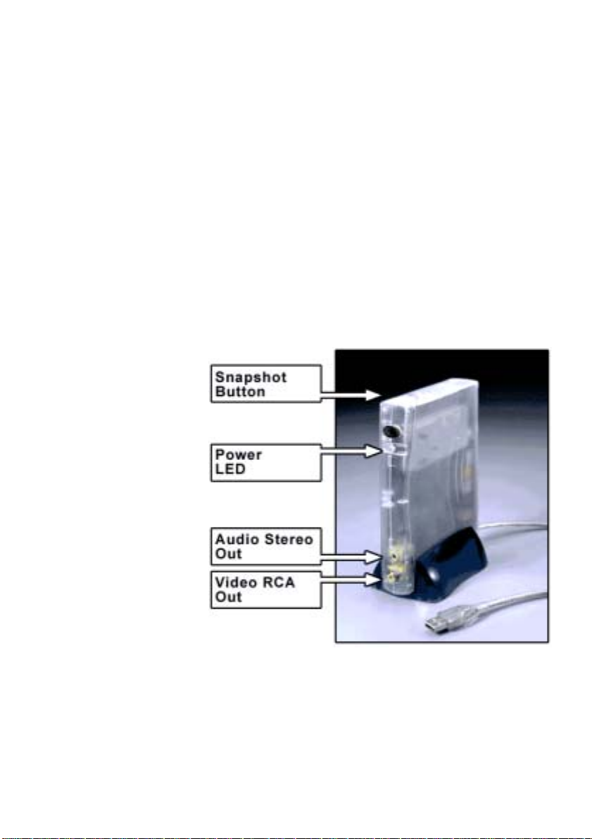
Front Panel
Snapshot
When pressed, the TV
Tuner software will
capture a single frame
from the video source.
Power LED
A green LED indicates
power status.
Audio Out
Used to connect the
DSB-T100 to an
external audio device such as PC Sound Card, TV, VCR or Camcorder.
Video Out
Used to connect the DSB-T100 to an external video device such as a TV,
VCR. Connect the yellow end of the video cable to this RCA jack.
7
Page 8
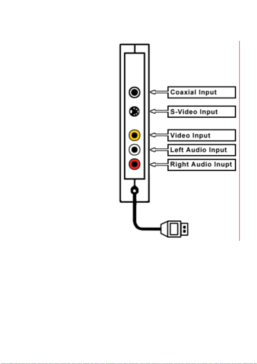
Rear Panel
Coaxial Input
Use when connecting to a
coaxial source such as Cable TV
or VCR.
S-Video Input
Use when connecting to an
S-Video source such as a TV or
VCR.
Video Input
Use when connecting to an RCA
video source. Connect the
yellow end of the video cable to
this RCA jack.
Left Audio Input
Use when connecting to an RCA
audio source. Connect the white
end of the audio cable to this
RCA jack.
Right Audio Input
Use when connecting to an RCA audio source. Connect the red end of the
audio cable to this RCA jack.
8
Page 9
Software Guide
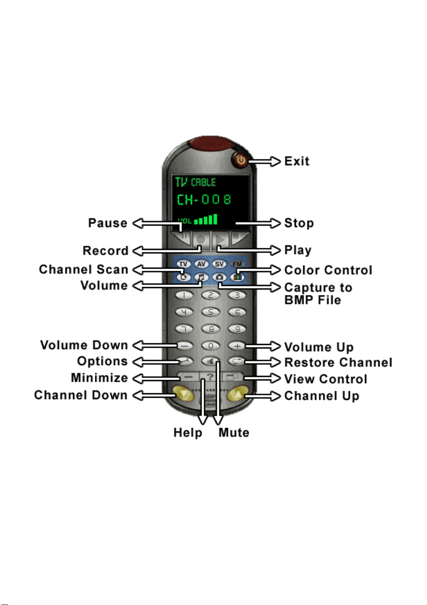
On-Screen Remote
When you start the TV Jukebox application an on-screen remote control will
appear. All options and features are controlled using the remote control.
9
Page 10
Below is a description of the major functions of the on-screen remote:
Press the TV button to play video from either cable or antenna.
Press the AV button to play video from a host of input devices such as VCD,
DVD, and VHS.
Press the SV button to play video from a host of input devices such as VCD,
DVD, and VHS.
Press the Channel Scan button to automatically scan channels that are
available for viewing from cable or antenna.
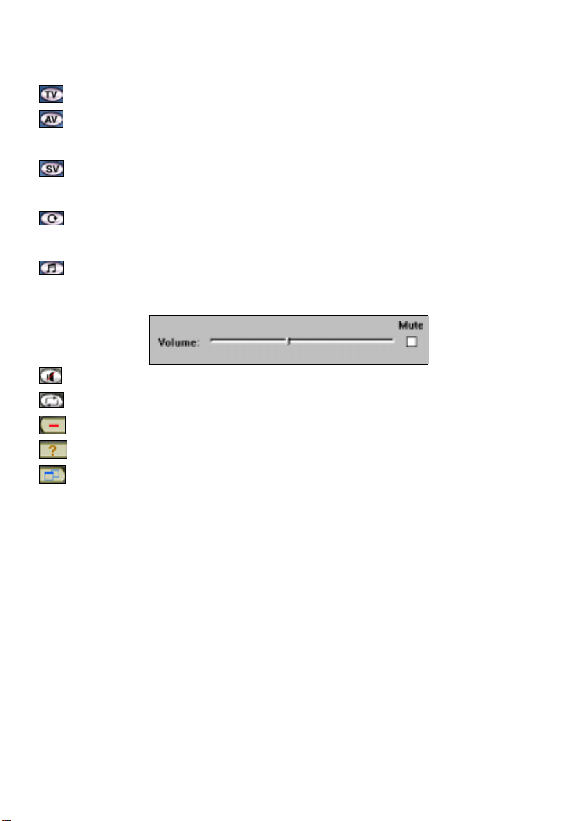
Press the Sound button and a pop up scroll bar will appear for adjusting the
sound level desired as illustrated below:
Press the Mute button to mute audio output.
Press the Restore Channel to jump to the previous channel.
Press the Minimize button to minimize the remote control.
Press the Help button to get help on using the remote control.
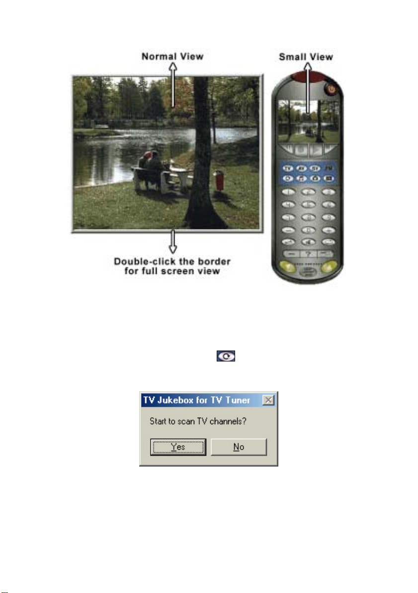
Press the View Control to change viewing screen from normal to small.
Note: From the View Control you have the options of Normal and Small
screen as illustrated. To activate the Full screen option double click on the
border of the normal screen and the Full screen option will be activated. To
return to normal screen press the "ESC" key on the keyboard.
10
Page 11
Scanning for Available Channels
You can scan for available channels while using a Cable or Antenna
connection. Click on the Channel Scan icon from the remote control
and a prompt will appear as shown below.
T o begin scanning click on the “Yes” icon and a new screen will appear with
the scanned channels appearing on the remote as illustrated below.
11
Page 12

12
Page 13

TV Jukebox Options
To configure the settings for the TV Tuner software click on the “Settings”
icon. The following menu will be shown:
Under “Tuner Control” you can select the Input Type from either a Cable
or Antenna source.
From the “Video Input System” you are able to select the TV Tuner
support system in your area. For example, NTSC, PAL, or SECAM.
The “Channel Table” lists all the channels available. Channels with
positive (+) means it will be available for viewing and channels with
negative (−) means the channel will not be available.
You can remove a specific channel by clicking the “Delete” button. The
13
Page 14

negative (−) sign will appear when you delete a channel from the list.
When changes are made, click the “Save” button to save all the new settings
you have set.
The “Device Process” tab allows you to change the sound card that will be
used for capture and playing sound. Click “OK” to save your changes.
14
Page 15

In the “Capture Process” tab, you can select the directory you want to save
the video recordings and snapshots captured from the USB TV Tuner.
The “Time limit” drop down box allows you to select the recording time
limit from 30 seconds up to 120 minutes or no limit. All files are saved in
AVI format. You can also change the Video Format to SP44 or RGB.
Choose the directory used to save the video recordings or snapshot photos
by clicking on Browse. The following screen will be shown:
15
Page 16

Browse your computers file system and choose a directory and press the
“OK” button.
When changes are made, click the “Save” button to save all the new settings
you have set.
How To Adjust Color
You can adjust the viewing color from the on-screen interface by clicking the
“Color Control” icon
viewing screen like the one below.
The color control allows 4 options to enhance the picture quality. These options
include brightness, contrast, hue and saturation. To change each of the options
mentioned above just click on the up or down “arrow button”
selection.
16
and an on-screen menu will pop up on the bottom of the
for the desired
Page 17

You can adjust each of the options by moving the “3D slide button” right (increase)
or left (decrease) for your desired choice
Click the “Reset” button to refresh the new setting. Clicking on the “Color
Control” icon
again will deactivate the color control.
How To Capture Still Images from Video
You can capture still video images from TV, AV or SV.
Click the "capture to .bmp file" icon on the remote control and an
on-screen menu will appear on the upper left side of the screen like the one
below.
By pressing the capture icon the still video image will be displayed up to a
maximum of 8 frames per row. You will be able to save the frames in .bmp
format for your collection.
To delete a frame, highlight the frame or frames you do not want and click
on the delete button.
Using the Snapshot button
The snapshot button on the DSB-T100 is used to capture still images; this
17
Page 18

function is supported by a TWAIN driver . The TWAIN driver can be
activated by an image editing software, like Windows Imaging or other
imaging software.
For example: After running Windows Imaging, (click on Start, Programs,
Accessory, Imaging). Click "File" on the menu bar and choose "Select
Scanner". After selecting the DSB-T100 as the scanner source, click "File"
from the menu bar and choose "Scan New". You can capture still pictures by
pressing the snapshot button on the TV Tuner or click the capture button on
the screen.
How To Capture Video
Follow these steps to capture video using the DSB-T100.
Run the TV Jukebox from the Start menu.
Set the desired settings using the
labeled “TV Jukebox Settings” for help on configuring the settings.
button. Refer to the section
Preview the channel or source you would like to capture in the view
window.
Press the “Record” button to begin recording.
Press the “Stop” button to stop recording.
A pop-up window will ask you if you want to save the captured video
to a new file. If you choose yes, you will be prompted to enter the
new file name. If you choose “No”, the video will be saved using the
settings in the options.
You can now use the bundled Ulead VideoStudio software to edit
and create your own video.
Remember that capturing video to your computer can take up a lot of disk
18
Page 19

space. Make sure that you have ample amount before attempting to capture a
large video sequence.
Uninstalling The USB TV Tuner Driver
In order to uninstall the DSB-T100, you must begin while the DSB-T100 is
still connected to your computer.
Open up the System Properties in Windows by double-clicking on
the System icon in the Control Panel or by right-clicking on My
Computer and clicking on properties.
Select Device Manager and click on the + sign next to “Imaging
Device” and select “D-Link, WDM Capture” as illustrated below.
19
Page 20

Click on the "Remove" button and a prompt will appear to confirm
the removal of the DSB-T100. Click on the "OK" button and the
driver will be uninstalled.
A prompt will appear asking to restart your computer, click on the
“No” icon to continue the uninstallation procedure.
Note:
For Windows 2000 O.S the above prompt will not appear.
Follow these steps to remove the USB controller of the TV Tuner
Driver. From the System Properties Menu, select Device Manager
and click on “Universal Serial Bus controllers” and select
“D-Link USB TV Tuner” as illustrated below.
20
Page 21

Click on the "Remove" button and a prompt will appear to confirm
the removal of the DSB-T100. Click on the "OK" button and the
device will be uninstalled.
A prompt will appear asking to restart your computer, click on the
“No” icon to continue the uninstallation procedure.
Note: W indows 2000 users will no t see the “restart your computer” prompt.
Open the Control Panel and double-click the “Add/Remove Programs”
icon.
21
Page 22

Select “D-Link USB TV Tuner & Video Capture” from the list and click
the “Add/Remove” button.
Select “Remove” from the Install Shield Wizard and click on the Next
button to continue.
Click on the “OK” button to confirm you want to completely remove the
application.
Click on the “Finish” button to finish the uninstall of the Driver.
22
Page 23

Uninstalling The USB TV Tuner AP
From the Start Menu, click Programs, TV Jukebox, Uninstall TV Jukebox.
Click the “Uninstall” icon to continue.
Once the uninstall process is finished, click on the “Exit” icon.
23
Page 24

Technical Specifications
System Requirements
Microsoft Windows 98, 98SE, ME or Windows 2000
300MHz Processor and Above
48MB RAM
500MB Hard Drive Space
CD-ROM Drive
16-bit SoundBlaster Compatible Sound Card
Video Adapter That Supports 24 Bit (16.7 Million Colors) Or
Greater Color
USB Port
Standards
USB Specification version 1.1
Interface
USB Type A
TV Tuner Support
NTSC, PAL, or SECAM
Input Connectors
TV/RF Phono
RCA Composite Video/AudioL/AudioR
S-Video Mini Din Jack
Output Connectors
RCA V ideo
Audio Phono
Performance
Video Playback and Capture up to 30 fps @ CIF
24
Page 25

D-Link Offices
AUSTRALIA D-LINK AUSTRALASIA
Unit 16, 390 Eastern Valley Way, Roseville, NSW 2069, Australia
TEL: 61-2-9417-7100 FAX: 61-2-9417-1077
TOLL FREE: 1800-177-100 (Australia), 0800-900900 (New Zealand)
URL: www.dlink.com.au E-MAIL: support@dlink.com.au, info@dlink.com.au
CANADA D-LINK CANADA
2180 Winston Park Drive, Oakville, Ontario L6H 5W1 Canada
TEL: 1-905-829-5033 FAX: 1-905-829-5095 BBS: 1-965-279-8732 FREE CALL: 1-800-354-6522
URL: www.dlink.ca E-MAIL: techsup@dlink.ca
CHILE D-LINK SOUTH AMERICA
Isidora Goyenechea #2934 of.702, Las Condes, Santiago, Chile
TEL: 56-2-232-3185 FAX: 56-2-2320923 URL: www.dlink.cl
CHINA D-LINK CHINA
2F., Sigma Building, 49 Zhichun Road, Haidian District, 100080 Beijing, China
TEL: 86-10-88097777 FAX: 86-10-88096789
URL: www.dlink.com.cn
DENMARK D-LINK DENMARK
Naverland 2, DK-2600 Glostrup, Copenhagen, Denmark
TEL:45-43-969040 FAX:45-43-424347 URL: www.dlink.dk
E-MAIL: info@dlink.dk
EGYPT D-LINK MIDDLE EAST
7 Assem Ebn Sabet Street, Heliopolis Cairo, Egypt
TEL: 202-2456176 FAX: 202-2456192 URL: www.dlink-me.com
E-MAIL: support@dlink-me.com
FRANCE D-LINK FRANCE
Le Florilege #2, Allee de la Fresnerie
78330 Fontenay Le Fleury France
TEL: 33-1-30238688 FAX: 33-1-3023-8689 URL: www.dlink-france.fr
E-MAIL: info@dlink-france.fr
GERMANY D-LINK GERMANY
Bachstrae 22, D-65830 Kriftel Germany
TEL: 49-(0)6192-97110 FAX: 49-(0)6192-9711-11
URL: www.dlink.de BBS: 49-(0)6192-971199 (Analog) 49-(0)6192-971198 (ISDN)
INFO LINE: 00800-7250-0000 (toll free) HELP LINE: 00800-7250-4000 (toll free)
REPAIR LINE: 00800-7250-8000
INDIA D-LINK INDIA
Plot No.5, Kurla-Bandra Complex Road,
Off Cst Road, Santacruz (E), Bombay - 400 098 India
TEL: 91-22-652-6696 FAX: 91-22-652-8914 URL: www.dlink-india.com
E-MAIL: service@dlink.india.com
ITALY D-LINK ITALIA
Via Nino Bonnet No. 6/b, 20154 Milano, Italy
TEL: 39-02-2900-0676 FAX: 39-02-2900-1723 URL: www.dlink.it
E-MAIL: info@dlink.it
JAPAN D-LINK JAPAN
10F, 8-8-15 Nishi-Gotanda, Shinagawa-ku, Tokyo 141 Japan
TEL: 81-3-5434-9678 FAX: 81-3-5434-9868 URL: www.d-link.co.jp
RUSSIA D-LINK RUSSIA
Michurinski Prospekt 49, 117607 Moscow, Russia
TEL: 7-095-737-3389, 7-095-737-3492 FAX: 7-095-737-3390
SINGAPORE D-LINK INTERNATIONAL
1 International Business Park, #03-12 The Synergy, Singapore 609917
TEL: 65-774-6233 FAX: 65-774-6322
URL: www.dlink-intl.com E-MAIL: info@dlink.com.s g
S. AFRICA D-LINK SOUTH AFRICA
Unit 2, Parkside 86 Oak Avenue
Highveld Technopark Centurion, Gauteng, Republic of South Africa
TEL: 27(0)126652165 FAX: 27(0)126652186
SWEDEN D-LINK SWEDEN
P.O. Box 15036, S-167 15 Bromma Sweden
TEL: 46-(0)8564-61900 FAX: 46-(0)8564-61901 E-MAIL: info@dlink.se
URL: www.dlink.se
TAIWAN D-LINK TAIWAN
2F, No. 119 Pao-Chung Road, Hsin-Tien, Taipei, Taiwan, R.O.C.
TEL: 886-2-2910-2626 FAX: 886-2-2910-1515 URL: www.dlinktw.com.tw
U.K. D-LINK EUROPE
4
TEL: 44-20-8731-5555 FAX: 44-20-8731-5511
URL: www.dlink.co.uk E-MAIL: info@dlink.co.uk
U.S.A. D-LINK U.S.A.
53 Discovery Drive, Irvine, CA 92618 USA
TEL: 1-949-788-0805 FAX: 1-949-753-7033 INFO LINE: 1-800-326-1688
BBS: 1-949-455-1779, 1-949-455-9616
URL: www.dlink.com E-MAIL: tech@dlink.com, support@dlink.com
Tech Support Hours: 6 A.M. to 6 P.M. Pacific Standar d Time. Monday through Friday
th
Floor, Merit House, Edgware Road, Colindale, London, NW9 5AB, U.K.
25
Page 26

Limited Warranty
D-Link Systems, Inc. (“D-Link”) provides this limited warranty for its
product only to the person or entity who originally purchased the product
from D-Link or its authorized reseller or distributor.
Limited Hardware Warranty: D-Link warrants that the hardware portion
of the D-Link products described below (“Hardware”) will be free from
material defects in workmanship and materials from the date of original
retail purchase of the Hardware, for the period set forth below applicable to
the product type (“W arranty Period”) if the Hardware is used and serviced in
accordance with applicable documentation; provided that a completed
Registration Card is returned to an Authoriz ed D-Link Service Of fice within
ninety (90) days after the date of original retail purchase of the Hardware. If
a completed Registration Card is not received by an authorized D-Link
Service Office within such ninety (90) day period, then the Warranty Period
shall be ninety (90) days from the date of purchase.
Product Type Warranty Period
Product (excluding power supplies and fans), if
purchased and delivered in the fifty (50) United
States, or the District of Columbia (“USA”)
Product purchased or delivered outside the USA One (1) Year
Power Supplies and Fans One (1) Year
Spare parts and spare kits Ninety (90) days
D-Link’s sole obligation shall be to repair or replace the def ective Hardware
One (1) Year
at no charge to the original owner. Such repair or replacement will be
rendered by D-Link at an Authorized D-Link Service Office. The
replacement Hardware need not be new or of an identical make, model or
part; D-Link may in its discretion may replace the defective Hardware (or
any part thereof) with any reconditioned product that D-Link reasonably
26
Page 27

determines is substantially equivalent (or superior) in all material respects to
the defective Hardware. The Warranty Period shall extend for an additional
ninety (90) days after any repaired or replaced Hardware is delivered. If a
material defect is incapable of correction, or if D-Link determines in its sole
discretion that it is not practical to repair or replace the defective Hardware,
the price paid by the original purchaser for the defective Hardware will be
refunded by D-Link upon return to D-Link of the defective Hardware. All
Hardware (or part thereof) that is replaced by D-Link, or for which the
purchase price is refunded, shall become the property of D-Link upon
replacement or refund.
Limited Software Warranty: D-Link warrants that the software portion of
the product (“Software”) will substantially conform to D-Link’ s then current
functional specifications for the Software, as set forth in the applicable
documentation, from the date of original delivery of the Software for a
period of ninety (90) days (“Warranty Period”), if the Software is properly
installed on approved hardware and operated as contemplated in its
documentation. D-Link further warrants that, during the Warranty Period,
the magnetic media on which D-Link delivers the Software will be free of
physical defects. D-Link’s sole obligation shall be to replace the
non-conforming Software (or defective media) with software that
substantially conforms to D-Link’s functional specifications for the
Software. Except as otherwise agreed by D-Link in writing, the replacement
Software is provided only to the original licensee, and is subject to the terms
and conditions of the license granted by D-Link for the Software. The
Warranty Period shall extend for an additional ninety (90) days after any
replacement Software is delivered. If a material non-conformance is
27
Page 28

incapable of correction, or if D-Link determines in its sole discretion that it
is not practical to replace the non-conforming Software, the price paid by the
original licensee for the non-conforming Software will be refunded by
D-Link; provided that the non-conforming Software (and all copies thereof)
is first returned to D-Link. The license granted respecting any Software for
which a refund is given automatically terminates.
What You Must Do For Warranty Service:
Registration Card. The Registration Card provided at the back of this
manual must be completed and returned to an Authorized D-Link Service
Office for each D-Link product within ninety (90) days after the product is
purchased and/or licensed. The addresses/telephone/fax list of the nearest
Authorized D-Link Service Office is provided in the back of this manual.
FAILURE TO PROPERLY COMPLETE AND TIMELY RETURN THE
REGISTRATION CARD MAY AFFECT THE WARRANTY FOR THIS
PRODUCT.
Submitting A Claim. Any claim under this limited warranty must be
submitted in writing before the end of the Warranty Period to an Authorized
D-Link Service Office. The claim must include a written description of the
Hardware defect or Software nonconformance in sufficient detail to allow
D-Link to confirm the same. The original product owner must obtain a
Return Material Authorization (RMA) number from the Authorized D-Link
Service Office and, if requested, provide written proof of purchase of the
product (such as a copy of the dated purchase invoice for the product) before
the warranty service is provided. After an RMA number is issued, the
defective product must be packaged securely in the original or other suitable
shipping package to ensure that it will not be damaged in transit, and the
28
Page 29

RMA number must be prominently marked on the outside of the package.
The packaged product shall be insured and shipped to D-Link, 53 Discovery
Drive, Irvine CA 92618, with all shipping costs prepaid. D-Link may reject
or return any product that is not packaged and shipped in strict compliance
with the foregoing requirements, or for which an RMA number is not visible
from the outside of the package. The product owner agrees to pay D-Link’s
reasonable handling and return shipping charges for any product that is not
packaged and shipped in accordance with the foregoing requirements, or
that is determined by D-Link not to be defective or non-conforming.
What Is Not Covered:
This limited warranty provided by D-Link does not cover:
Products that have been subjected to abuse, accident, alteration,
modification, tampering, negligence, misuse, faulty installation, lack of
reasonable care, repair or service in any way that is not contemplated in the
documentation for the product, or if the model or serial number has been
altered, tampered with, defaced or removed;
Initial installation, installation and removal of the product for repair, and
shipping costs;
Operational adjustments covered in the operating manual for the product,
and normal maintenance;
Damage that occurs in shipment, due to act of God, failures due to power
surge, and cosmetic damage; and
Any hardware, software, firmware or other products or services provided by
anyone other than D-Link.
Disclaimer of Other Warranties: EXCEPT FOR THE LIMITED
29
Page 30

WARRANTY SPECIFIED HEREIN, THE PRODUCT IS PROVIDED
“AS-IS” WITHOUT ANY WARRANTY OF ANY KIND INCLUDING,
WITHOUT LIMITATION, ANY WARRANTY OF MERCHANTABILITY,
FITNESS FOR A PARTICULAR PURPOSE AND
NON-INFRINGEMENT. IF ANY IMPLIED WARRANTY CANNOT BE
DISCLAIMED IN ANY TERRITORY WHERE A PRODUCT IS SOLD,
THE DURATION OF SUCH IMPLIED WARRANTY SHALL BE
LIMITED TO NINETY (90) DAYS. EXCEPT AS EXPRESSLY
COVERED UNDER THE LIMITED WARRANTY PROVIDED HEREIN,
THE ENTIRE RISK AS TO THE QUALITY, SELECTION AND
PERFORMANCE OF THE PRODUCT IS WITH THE PURCHASER OF
THE PRODUCT.
Limitation of Liability: T O T HE MAXIMU M EXTENT PERMITTED BY
LAW, D-LINK IS NOT LIABLE UNDER ANY CONTRACT,
NEGLIGENCE, STRICT LIABILITY OR OTHER LEGAL OR
EQUITABLE THEORY FOR ANY LOSS OF USE OF THE PRODUCT,
INCONVENIENCE OR DAMAGES OF ANY CHARACTER, WHETHER
DIRECT , SPECIAL, INCIDENTAL OR CONSEQUENTIAL (INCLUDING ,
BUT NOT LIMITED TO, DAMAGES FOR LOSS OF GOODWILL,
WORK STOPPAGE, COMPUTER FAILURE OR MALFUNCTION,
LOSS OF INFORMATION OR DATA CONTAINED IN, STORED ON,
OR INTEGRATED WITH ANY PRODUCT RETURNED TO D-LINK
FOR WARRANTY SERVICE) RESULTING FROM THE USE OF THE
PRODUCT, RELATING TO WARRANTY SERVICE, OR ARISING OUT
OF ANY BREACH OF THIS LIMITED WARRANTY, EVEN IF D-LINK
HAS BEEN ADVISED OF THE POSSIBILITY OF SUCH DAMAGES.
30
Page 31

THE SOLE REMEDY FOR A BREACH OF THE FOREGOING LIMITED
WARRANTY IS REPAIR, REPLACEMENT OR REFUND OF THE
DEFECTIVE OR NON-CONFORMING PRODUCT.
GOVERNING LAW: This Limited Warranty shall be governed by the laws
of the state of California.
Some states do not allow exclusion or limitation of incidental or consequential
damages, or limitations on how long an implied warranty lasts, so the
foregoing limitations and exclusions may not apply . This limited warranty
provides specific legal rights and the product owner may also have other rights
which vary from state to state.
Trademarks
Copyright 1999 D-Link Corporation. Contents subject to change without
prior notice. D-Link is a registered trademark of D-Link
Corporation/D-Link Systems, Inc. All other trademarks belong to their
respective proprietors.
Copyright Statement
No part of this publication may be reproduced in any form or by any means or
used to make any derivative such as translation, transformation, or
adaptation without permission from D-Link Corporation/D-Link Systems
Inc., as stipulated by the United States Copyright Act of 1976.
CE Mark Warning
This is a Class B product. In a domestic environment, this product may
cause radio interference, in which case the user may be required to take
adequate measures
31
Page 32

Warnung!
Dies ist in Produkt der Klasse B. Im Wohnbereich kann dieses Produkt
Funkstoerungen verursachen. In diesem Fall kann vom Benutzer verlangt
werden, angemessene Massnahmen zu ergreifen.
Advertencia de Marca de la CE
Este es un producto de Clase B. En un entorno doméstico, puede causar
interferencias de radio, en cuyo case, puede requerirse al usuario para que
adopte las medidas adecuadas.
Attention!
Ceci est un produit de classe B. Dans un environnement domestique, ce
produit pourrait causer des interférences radio, auquel cas l`utilisateur
devrait prendre les mesures adéquates.
Attenzione!
Il presente prodotto appartiene alla classe B. Se utilizzato in ambiente
domestico il prodotto può causare interferenze radio, nel cui caso è possibile
che l`utente debba assumere provvedimenti adeguati.
FCC Warning
This equipment has been tested and found to comply with the limits for a
Class B digital device, pursuant to part 15 of the FCC Rules. These limits are
designed to provide reasonable protection against harmful interference in a
residential installation. This equipment generates, uses and can radiate radio
frequency energy and, if not installed and used in accordance with the
32
Page 33

instructions, may cause harmful interference to radio communications.
However, there is no guarantee that inte rference will not occur in a particular
installation. If this equipment does cause harmful interference to radio or
television reception, which can be determined by turning the equipment off
and on, the user is encouraged to try to correct the interference by one or
more of the following measures:
-Reorient or relocate the receiving antenna.
-Increase the separation between the equipment and receiver.
-Connect the equipment into an outlet on a circuit different from that to
which the receiver is connected.
-Consult the dealer or an experienced radio/ TV technician for help.
VCCI Warning
33
Page 34

Register by mail or online at http://www.dlink.com/sales/reg/
Registration Card
Print, type or use block letters.
Your name: Mr./Ms _____________________________________________________________________________
Organization: ________________________________________________ Dept. ____________________________
Your title at organization: ________________________________________________________________________
Telephone: _______________________________________ Fax:________________________________________
Organization's full address: ______________________________________________________________________
____________________________________________________________________________________________
Country: _____________________________________________________________________________________
Date of purchase (Month/Day/Year): _______________________________________________________________
Product Model Product Serial No. * Product installed in type of
(* Applies to adapters only)
Product was purchased from:
Reseller's name: ______________________________________________________________________________
Telephone: _______________________________________ Fax:________________________________________
Reseller's full address: _________________________________________________________ ___ _____________
_________________________________________________________________________
_________________________________________________________________________
Answers to the following questions help us to support your product:
1. Where and how will the product primarily be used?
Home Office Travel Company Business Home Business Personal Use
2. How many employees work at installation site?
1 employee 2-9 10-49 50-99 100-499 500-999 1000 or more
3. What network protocol(s) does your organization use?
XNS/IPX TCP/IP DECnet Others_____________________________
4. What network operating system(s) does your organization use?
D-Link LANsmart Novell NetWare NetWare Lite SCO Unix/Xenix PC NFS 3Com 3+Open
Banyan Vines DECnet Pathwork Windows NT Windows NTAS Windows '95
Others__________________________________________
5. What network management program does your organization use?
D-View HP OpenView/Windows HP OpenView/Unix SunNet Manager Novell NMS
NetView 6000 Others________________________________________
6. What network medium/media does your organization use ?
Fiber-optics Thick coax Ethernet Thin coax Ethernet 10BASE-T UTP/STP
100BASE-TX 100BASE-T4 100VGAnyLAN Others_________________
7. What applications are used on your network?
Desktop publishing Spreadsheet Word processing CAD/CAM
Database management Accounting Others_____________________
8. What category best describes your company?
Aerospace Engineering Education Finance Hospital Legal Insurance/Real Estate Manufacturing
Retail/Chainstore/Wholesale Government Transportation/Utilities/Communication VAR
System house/company Other________________________________
9. Would you recommend your D-Link product to a friend?
Yes No Don't know yet
10.Your comments regarding this product?
__________________________________________________________________________________________
__________________________________________________________________________________________
computer (e.g., Compaq 486)
* Product installed in
computer serial No.
34
Page 35

35
Page 36

36
M20010301
 Loading...