

Page 1

D-Link
Express EtherNetwork
DSA-3100
Hotspot Gateway
Manual
TM
January 2004
Fourth Edition
Building Networks for People
Page 2

Contents
Package Contents ................................................................................3
Introduction...........................................................................................4
Front Panel...........................................................................................5
Rear Panel ...........................................................................................6
Features ...............................................................................................7
Sample Scenarios ................................................................................8
Installation ..........................................................................................10
Setting Up the DSA-3100 ...................................................................11
Configure PCs on your LAN ...............................................................12
TCP/IP Network Setting .....................................................................12
Internet Access Configuration ............................................................13
Using the Configuration Utility ............................................................15
Networking Basics..............................................................................55
Technical Specifications .....................................................................68
Technical Support...............................................................................70
Warranty and Registration..................................................................71
2
Page 3

Package Contents
Contents of Package:
D-Link DSA-3100 Hotspot Gateway
1
CD-ROM (containing Manual and Warranty)
2
Quick Installation Guide
3
4
5
7
If any of the above items are missing, please contact your reseller.
Two (2) CAT5 UTP/Straight-through (Ethernet) cables
One (1) CAT5 UTP/Cross-over cable
6
One (1) Console cable
5V DC, 3A Power Adapter
System Requirements for Configuration:
Computers with Windows, Macintosh, or Linux-based
operating systems with an installed Ethernet adapter
Internet Explorer Version 6.0 or Netscape Navigator
Version 6.0 and Above
3
Page 4

Introduction
The D-Link DSA-3100 Hotspot Gateway is a simple-to-use network access control
system supporting Ethernet, Fast Ethernet or an IEEE 802.11 wireless LAN (WLAN)
separately and simultaneously.
The DSA-3100 can be configured with a standard HTML browser (i.e., Internet Explorer ,
Netscape Navigator) operating on Windows 98SE/Me/2000/XP, Macintosh OS 9, Mac
OS X (v10.1.5 or later), Linux, or Pocket PC 2000/2002. The DSA-3100 allows the
operator to offer wired or wireless networking services and access to the Internet
when used with a switch or wireless access point respectively. The device features
many management settings allowing for private and public access to the Internet and
the necessary privilege mechanisms to permit this usage.
4
Page 5
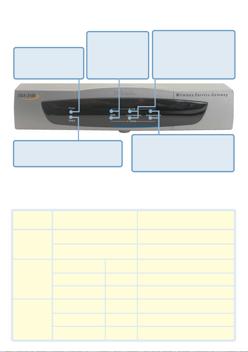
Front Panel
WAN LEDs - a solid
light indicates
Power LED - a solid
light indicates a proper
connection to the power
supply.
Status LED - a solid light on the port
indicates a connection to an Ethernet
network.
The Power Indicator remains illuminated when the DSA-3100 is on. The indicators for
WAN, Local Network, Authentication each have two LED indicators. When CAT5
(Ethernet) cables are plugged into the corresponding port, the upper LED will illuminate
to indicate that a connection has been established. The lower LED will blink whenever
data is transmitted or received.
connection on the
WAN port. The LED
below blinks during
data transmission
Authentication LEDs - a solid light
on the port indicates a connection
from the Authentication port for a
Public Network. The LED below
blinks during data transmission.
Local Network LEDs - a
solid light on the port
indicates a connection from
the Local Network port for a
Private Network. The LED
below blinks during data
transmission.
Power
Status
Link
Activity
Green LED
Green LED
Blinking LED
WAN
Local Network
Authentication
WAN
Local Network
Authentication
Green
Green
Green
Blinking
Blinking
Blinking
5
System is ready
System is ready
System is rebooting or
Firmware upgrading
On line
On line
On line
Data is being transmitted
Data is being transmitted
Data is being transmitted
Page 6
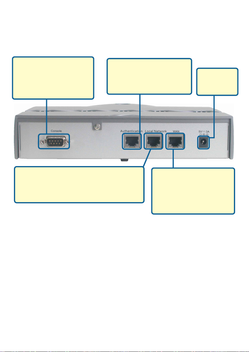
Rear Panel
Console Port -
For resetting to factory
defaults, or reconfiguring
the device. For Advanced
users only!
Local Area Network Port (Private LAN)-
Connects to a switch for a private network.
Does not require authentication to access
the Internet.
Authentication Port
(Public LAN or WLAN with
Access Point) -
Connects to a switch or AP.
Receptor for
Power
Adapter.
WAN Port -
The port that connects to
your WAN connection
providing Internet access to
the Local and Managed
Networks.
6
Page 7

Features
Creates two separate and discreet networks allowing the owner/
administrator to create a wired or wireless hotspot and provide
Internet access to visitors, guests, or customers to your company or
organization.
Manages up to 250 user accounts with internal database.
Supports at least 50 users accessing the Internet at any given time.
Allows ID/Password-based authentication and authorization (can
also be combined with MAC address locking for even
stricter access control).
Supports either POP3, RADIUS, or LDAP external authentication
servers.
Provides on-line status monitoring and historical traffic data.
SSL-protected access to the administration interface and user
authentication interface.
Customizable user log-in and log-out Web interface.
Customizable user log-out timer.
Customizable target URL for users who successfully authenticate.
Console mode administration interface via serial console port.
Supports display of text messages on the log-in page. An
administrator could use the administration interface to input mes
sages (promotions, alerts, additional usage time/services with
corresponding fees).
Supports NAT for managed clients.
Supports static IP, DHCP client and PPPoE client on the WAN
interface.
Built-in DHCP server to manage clients.
Built-in, high-speed policy routing engine.
Customizable peremptory traffic redirection (IP and Port-Redirect).
Built-in NTP client.
7
Page 8
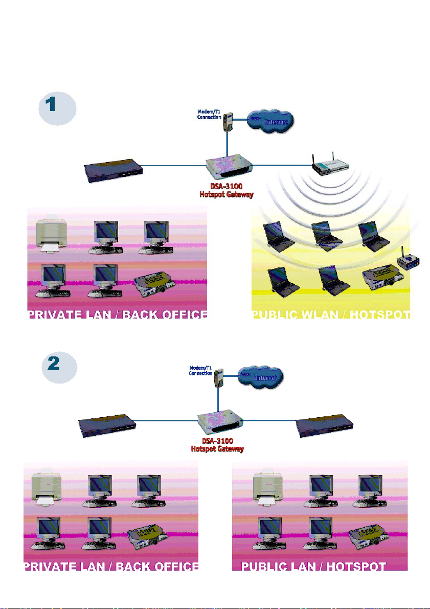
Sample Scenarios
8
Page 9
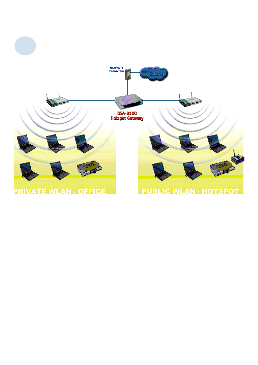
Sample Scenarios (continued)
3
9
Page 10
Installation
Requirements
Standard 10/100Base-T network (UTP/Cat5 Ethernet) cable
with RJ45 connectors.
TCP/IP network protocol must be installed on all networked
computers and related devices.
10
Page 11

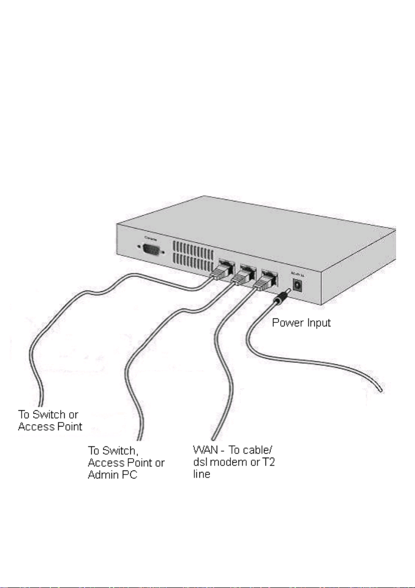
Setting up the DSA-3100
Make sure the DSA-3100 unit is not connected to the power
adapter and is powered OFF.
WAN port connection
Use 10/100BaseT connections to connect the unmanaged network.
The unmanaged network’s interface may be the ADSL router’s LAN
port, cable modem’s LAN port or Intranet switch port.
Private LAN port connection
Use a straight-through cable to connect your admin PC with the
internal switch or hub that is connected to the local network port on
the DSA-3100. If you want to directly connect the DSA-3100 to this
PC or the wireless AP, use a crossover cable.
Public LAN port connection
Use a straight-through cable to connect your client PC with the
internal switch or hub that is connected to the authentication port on
DSA-3100. If you want to directly connect the DSA-3100 to this PC or
the wireless AP, use a crossover cable.
Power ON
Connect the supplied power adapter to the DSA-3100 and insert the
plug on the other end into an electric outlet.
Check the LED
The power LED and WAN LED should be ON, if the
corresponding WAN port is connected to an active cable/DSL
modem or T1 line.
The corresponding local network or authentication indicator should
be ON if a network device is connected to the local network port or
the authentication internal port.
11
Page 12

Configure PCs on your LAN
After installing the DSA-3100, each computer’s TCP/IP network setting and Internet
access configuration may need to be re-configured:
TCP/IP network setting
If your PC uses the default Windows XP/2000/Me/98SE setting, no
changes need to be made. Just start/restart your PC.
If you are running Mac OS 9 or OS X, set your network settings to
DHCP and select Apply.
DSA-3100 will act as a DHCP Server, automatically providing a
suitable IP address (and related information) to each computer
when the computer reboots or when the network settings refresh.
For all non-Server versions of Windows, the default TCP/IP setting
is to act as a DHCP client. In Windows, this is called Obtain an IP
address automatically.
If you are using a fixed IP address on your LAN, or if you want to check
your TCP/IP setting, refer to the Networking Basics section in
this manual.
12
Page 13
Internet Access Configuration
To configure your PCs to use the DSA-3100 for Internet access, follow this
procedure.
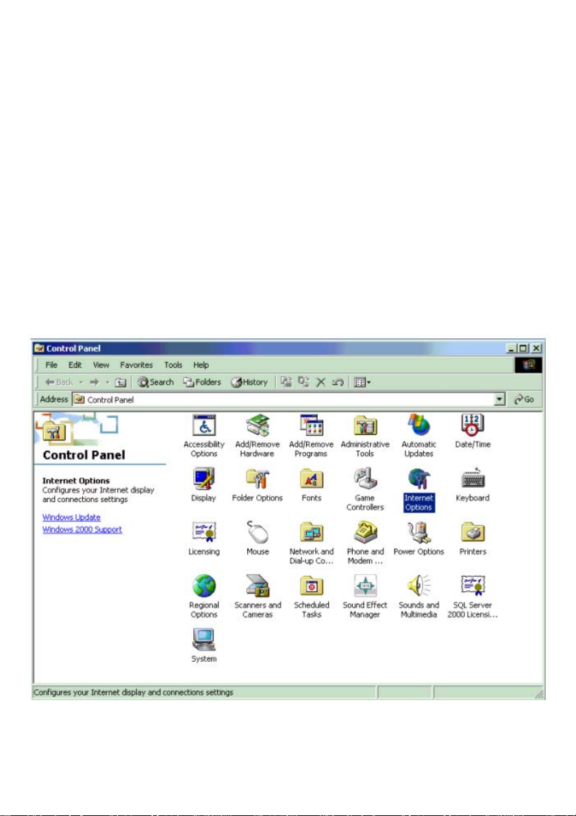
For Windows 9x/2000
Please select Start Menu - Control Panel - Internet Options.
Select the Connection tab, and click the Setup button.
Select “I want to set up my Internet connection manually, or I want to
connect through a local Area network (LAN)” and click next.
13
Page 14
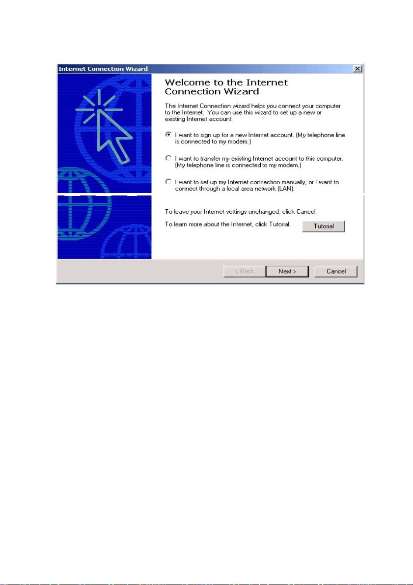
Internet Access Configuration (continued)
Select “I connect through a local area network (LAN)” and click Next.
Ensure all of the boxes on the local area network Internet configuration
screen are unchecked.
Check No, when promoted “Do you want to set up an Internet mail
account now?”
Click Finish to close the Internet Connection Wizard. Setup is now
completed.
For Windows XP
Please select Star Menu - Control Panel - Network and Internet
Connection.
Select the Connection tab, and click the Setup button.
Click Next on the New Connection Wizard screen.
Select Connect to the Internet and click Next.
Select Set up my connection manually and click Next.
Check Connect using a broadband connection this always on and click
Next.
Click Finish to close the New Connection Wizard. Setup is now completed.
14
Page 15
Using the Configuration Utility
To configure the DSA-3100, use a computer which is connected to the local network
port of the DSA-3100 with an Ethernet cable.
First, disable the Access the Internet using a proxy server function. To
disable this function, go to Control Panel > Internet Options > Connections
> LAN Settings and uncheck the enable box.
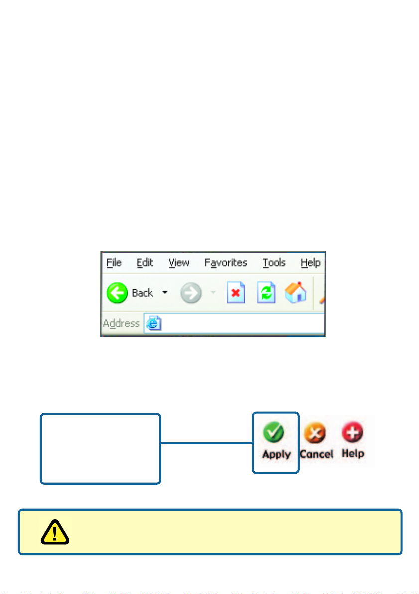
Start your Microsoft Internet Explorer Web browser program.
Type the IP address of the DSA-3100 (the default IP address is
192.168.0.40) in the address field and press Enter. Make sure that the IP
addresses of the DSA-3100 and your computer are in the same subnet.
https://192.168.0.40
On the bottom of each configuration screen you will find the buttons shown below.
Click Apply in each
screen of the
Configuration Utility
in which you have
made changes.
Restart the DSA-3100 after completing any changes to its
configuration.
15
Page 16
Using the Configuration Utility (continued)
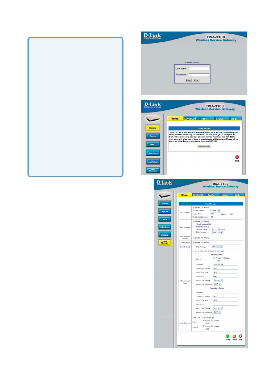
Log-in Screen
You can log in as admin or as
manager.
admin - the administrator of the
DSA-3100.
User Name: admin
Password: admin
manager - access to the man-
ager user account only.
User Name: manager
Password: manager
After you log in, click Enter.
Home > Wizard
The Home>Wizard screen will appear if you
logged in as an admin. For more information
on the Setup Wizard, please see the Quick In-
stallation Guide,included with your purchase.
You can access the configuration features from
this window.
Home > User Manager
The Home>User Manager screen will appear
if you logged in as a manager. Please refer to
the Quick Installation Guide for more information regarding the Setup Wizard. This screen
will be explained in more detail in the following
pages.
16
Page 17
Using the Configuration Utility (continued)
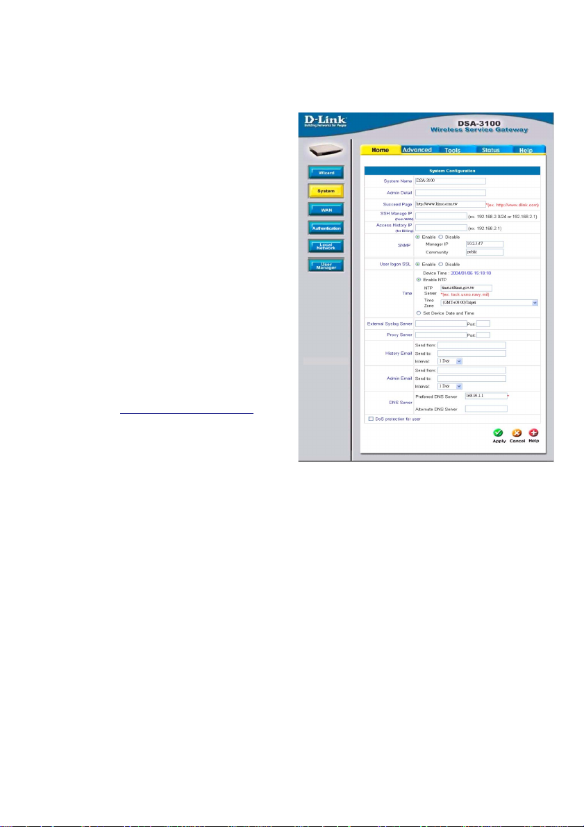
System Name:
DSA-3100 is the default system name.
You may wish to rename it to indicate
your company, department, or the
service you would like to provide.
Home > System
Admin Detail:
You can edit the System Administrator’s
information here (e.g., name, phone
number, and e-mail). If a user encounters
a problem connecting to the WAN Port of
the DSA-3100, the system administrator’s
information will be shown on the user
login page
Succeed Page:
Enter a URL for all users to be directed
to after successful login, typically defined
as the home page of the host company,
for instance: http://www.dlink.com. No
matter to which URL a user originally
attempts to connect, he/she will be
directed to the URL defined here first.
SSH Manage IP:
Specify an IP address that connect s to the W AN Port that will be allowed to configure
the DSA-3100. For instance, if 10.2.3.1 is specified, then the user will be allowed to
connect to the WAN Port and configure the DSA-3100 only from the specified address.
Access History IP:
Specify an IP address to be used by the billing system to connect to the DSA-3100
to get billing history information.
SNMP:
Simple Network Management Protocol is a system for managing complex networks.
The DSA-3100 provides SNMP v2 Read-only(RO) management.
Manager IP: A trap manager is a management station that receives and
processes traps. When you configure a trap manager, assign the IP address
to the management station.
Community: Community strings serve as passwords for SNMP
messages. DSA-3100 allows Read-only (RO) as a password.
If you Enable SNMP, enter the IP address and the community string in the field.
continued -
17
Page 18

Using the Configuration Utility (continued)
Home >System (continued)
User Logon
SSL:
Select Enable or Disable
Time:
External
Syslog
Server:
Proxy
Server:
History
Email:
Admin
Email:
DNS:
Y ou may use NTP (Network T ime Protocol) or you may input the time
yourself. To use NTP please specify a timeserver’s domain name and
select the time zone.The time zone of the DSA-3100’s internal clock
is UTC (Coordinated Universal Time, formerly known as GMT,
Greenwich Mean Time).
Specify the IP address and the Port of the External Syslog server.
Specify the IP address and the Port of the Proxy server. (The DSA3100 supports Http proxy.
Send from: Indicate the IP address from which the email will be sent
Send to: Indicate the IP address to which the email will be sent
Interval: Indicate the interval at which the email will be sent
Send from: Indicate the IP address from which the email will be sent
Send to: Indicate the IP address to which the email will be sent
Interval: Indicate the interval at which the email will be sent
Specify DNS servers for the DSA-3100 for the Preferred DNS
(preferred IP address) and Alternate DNS (alternate IP address).
DoS
protection
for user:
The DSA-3100 protects users against various hacker attacks including:
NMAP FIN/URG/PSH
Xmas Tree
SYN/RST,
Ping of Death
Null Scan
SYN/FIN
18
Page 19

Using the Configuration Utility (continued)
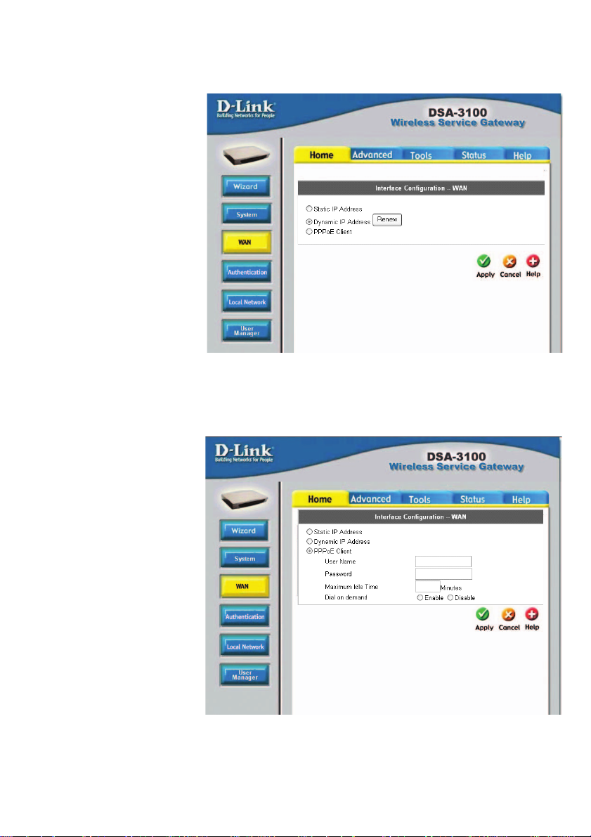
Home > WAN > Static IP Address
Static IP
Address:
Dynamic IP
Address:
PPPoE
Client:
IP address:
Subnet
mask:
Default
Gateway:
Make this selection if there is a DHCP server in the network.
(See the following pages.)
Make this selection if you connect to the Internet using DSL.
(See the following pages.)
Enter the IP address provided to you by your ISP.
Enter the subnetmask provided to you by your ISP. All
devices on the network must share the same netmask.
Enter the IP address of the gateway, provided to you
by your ISP.
19
Page 20
Using the Configuration Utility (continued)
Home > WAN > Dynamic IP Address
Select this option to obtain an IP address automatically
from your ISP.
Home > WAN > PPPoE
User Name &
Password:
Maximum Idle Time
& Dial on demand:
Enter the user name and password that is assigned by
your ISP.
These fields are optional.
20
Page 21
Using the Configuration Utility (continued)
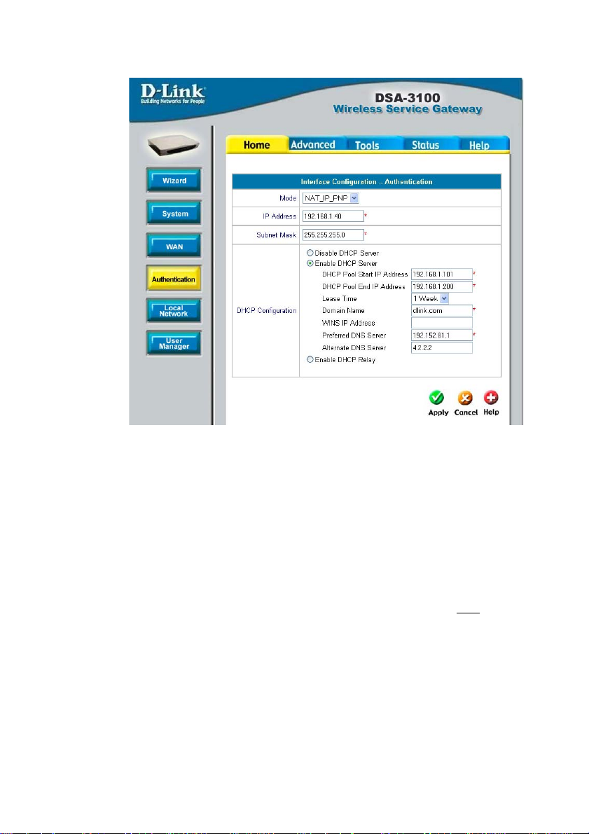
Home > Authentication
The DSA-3100 allows the gateway to be set to one of three Authentication modes.
Mode:
IP Address:
Subnet
Mask:
Disable
DHCP
Server:
Select NAT; NAT_IP_PNP or Router
NA T:
NA T_IP_PNP:
Router:
Enter the IP address for the Authentication interface (e.g., the RADIUS
server in the network).
Enter the subnet mask for the Authentication interface
Make this selection if you do not wish to use the built-in DHCP
feature in the DSA-3100
This mode protects the identity of the devices within
the LAN from those devices outside the network.
All devices, regardless of their IP address, can gain
access to the Internet through the DSA-3100 in this
mode.
In this mode, the DSA-3100 will not protect the
identity of the connected devices by translating their
IP addresses and shielding them from detection
outside the LAN.
21
continued -
Page 22

Using the Configuration Utility (continued)
Home > Authentication (continued)
Enable
DHCP
Server:
Selecting this option activates the device’s built-in DHCP server.
Configure the DHCP server with the following properties:
Enable
DHCP
Relay:
DHCP Pool
St art IP
Address:
DHCP Pool
End IP
Address:
Lease Time:
Domain
Name:
WINS IP
Address:
Preferred
DNS Server:
Alternate
DNS
Server:
Select this mode to specify another DHCP server’s IP address.
Enter the starting IP address, from which group of addresses
the DHCP server will assign IP addresses to the DHCPenabled devices (clients) on the network.
Enter the last IP address in the sequence of addresses from
which the DHCP server will assign addresses.
Select the length of time during which the DHCP assigned
address will be in effect.
Enter the domain name.
Enter the WINS server’s IP address.
Enter the IP address of the preferred DNS server.
Enter the IP address of the alternate DNS server.
22
Page 23

Using the Configuration Utility (continued)
Home > Local Network
NAT and Router are the two local network port modes.
Nat mode: All outbound IP addresses on the local network port will be
translated to the IP address of the WAN port to proceed.
Router mode: All outbound IP addresses on the local network port will
retain their IP addresses.
For an explanation of each field on this screen, please see the previous screen:
Home > Athentication
23
Page 24

Using the Configuration Utility (continued)
Home > User Manager
User Control:
Session
Length:
Logout Timer:
Multiple Login:
Guest Account:
Select Enable to define Logout TImer and Multiple Login:
Limit the duration of each session established by the
general account from 5 minutes to an unlimited period.
When enabled, on-line users who become inactive on
the network after a specified period of time will be logged
out automatically. The period can range from 1~1440.
10 minutes of time is the default value.
Check this function to allow a single user account to log
into the system multiple times.
Select Enable to activate the Guest Account feature for visitors
24
Page 25

Using the Configuration Utility (continued)
Home > User Manager > Guest Accounts (continued)
Guest Account List:
Up to 10 guest accounts can
be defined. To activate a particular Guest Account, simply
enter the corresponding password in the Password column
and click Apply.
Guest Account ACL:
Define network areas where
Guest Account is disallowed
access, for instance 10.2.3.0/24.
Session Length:
You have the option to limit
the duration for each session
established by Guest
Account, from 1~12 hours.
There is no limit to the
duration by default.
Logout Timer:
Logouts user if guest didn’t access the Internet for a certain
period.
Rate Average:
Limit the outbound traffic
bandwidth for each session
established by a Guest
Account. There is no limit by
default.
25
Page 26

Using the Configuration Utility (continued)
Home > User Manager > MAC ACL Control
MAC
Address
Control:
When MAC address control is enabled, users connected to the Authentication Port can not login to the DSA-3100 unless they have registered their MAC Address at MAC Address Control. In other words,
only 40 users will be allowed to login when this function is enabled.
Please refer to the configuration screen as follows.
Note: MAC address format is XX:XX:XX:XX:XX:XX or XX-XX-XX-XX-XX-XX. A newly
created user account will be valid instantly . Restarting the DSA-3100 is not necessary .
26
Page 27

Using the Configuration Utility (continued)
Home > User Manager (continued)
Friendly
logout:
Default
Group:
Management
Type:
Local:
If you enable Friendly logout, a pop-up window asking “Do you want to
logout?” will appear after closing the login window. If you disable this
function, no pop-up window will appear.
Limit the outbound traffic bandwidth
for On-demand users, RADIUS users,
LDAP users, POP3 users to an average rate from 190Kbps-1Mbps.
Supports multiple user authentication methods including Local,
POP3 Server, RADIUS Server, and LDAP Server.
User accounts are stored in the embedded database on the DSA-3100.
Local Users List: A
list of all local user
accounts stored in
the embedded
database for user
account
management.You can
add, edit, and delete
users. A sample list is
shown here.
Delete User: Click the box next to the user name and click
Delete.
Add Users: Click Add User to create new accounts. The
screen on the following page will appear.
27
Page 28

Using the Configuration Utility (continued)
Home > User Manager > Management Type > Local > Local Users List
Add Users:
Create new accounts, including Username (mandatory),
Password (mandatory), and MAC (optional), and assign to a
user group as shown above.
Edit Account:
Make changes to the account by clicking on the User Name as
indicated above. When the screen below appears, edit the
account information.
28
Page 29

Using the Configuration Utility (continued)
Home > User Manager > Management Type > Local > Local Users List
Upload User Accounts:
Besides adding user accounts one by one through the Web
interface, you can prepare a text file, which contains user account
information, store it on your hard drive and then upload it to the
DSA-3100.
Each line of the text file can be in one of the following two formats:
Please note that there must be no space or other characters
between the user ID, password and the MAC address. The MAC
address could be omitted, but the trailing comma must be
retained. A user ID should be between 1 to 32 characters and
the password should be between 0 to 20 characters. Special
characters are not allowed for user name and password.
After you have created the text file for the user account as
described above, click Upload User Accounts as shown in the
illustration at the top of this page. Click Browse and highlight the
text file you have created.
Click Refresh for the latest information. Click Apply to update
your changes.
Caution: When adding user accounts by uploading a file, existing accounts with the same ID will be replaced by the new ones.
29
Page 30

Using the Configuration Utility (continued)
Welcome!
----------------------- Username: D-Link1
Password: q6m34m3b
Price: US$2
Usage: 60 minute(s)
----------------------- ESSID:
dlink
Shared WEP Keys
(HEX 40 bit):
1:
2:
3:
4:
----------------------- Valid to use until:
2003/09/09 12:46:56
----------------------- Thank You!
Home > User Manager > Management Type > Local > On-demand
User Configuration
On-demand User: When you connect the DSA-3100P (the plug and play receipt
printer) to the DSA-3100’s console port, you can create a database of up to 2000
on-demand users. By default, the on-demand user database is empty. While you
press the DSA-3100P’s button, the on-demand user will be created in the database,
a receipt will then be printed which will contain the on-demand user’s information.
Shown above is an example of a an on-demand receipt.
30
Page 31

Using the Configuration Utility (continued)
Home >User Manager >Management Type >Local >Ondemand User Configuration (continued)
Field
Store Name
Account Range
Receipt Header
Receipt Footer
Printer baud rate
Account expires
after __ days
Session expire
after __ minutes
Logout timer
WLAN ESSID
WEP Key
Price
Description
You can specify the prefix of the user name. The maximum
is 8 characters (e.g., D-Link).
You can specify the maximum user amount which cannot
exceed 2000.
You can configure the receipt’s header in this field.
You can configure the receipt’s footer in this field.
You can specify the baud rate to support a specific printer.
The default setting is 9600.
You can specify the days before expiration in this field.
After the expiration date the user account will no longer be
available. A new session will be required.
You can specify how many minutes this account will be
available after successful login.
Logout user if the guest didn’t access the Internet for a
certain period.
You can specify the access point’s ESSID in this field.
You can specify the access point’s WEP key in the WEP
key field.
You can specify the price in this field.
31
Page 32

Using the Configuration Utility (continued)
Home > User Manager > Management Type > Local > Ondemand User Configuration (continued)
User List
Click User List in the previous screen and the
screen above will appear showing a list of the
on-demand users. You can delete users in this
window.
Local > Local User Group Configuration
The DSA-3100 provides 5 local user groups; each group can
designate a different outbound traffic bandwidth. The Logout Timer
will logout a user that has not accessed the Internet for a certain
time period. A sample list is shown below.
32
Page 33

Using the Configuration Utility (continued)
Home > User Manager > Management Type > POP3
To use POP3 as the authentication method, input the POP3 server IP address or
domain name and its POP3 server port. The settings will take ef fect immediately af ter
you click the Apply button. It is recommended that you restart the DSA-3100 after
these changes if there are any online users.
Home > User Manager > Management Type > RADIUS
To use RADIUS as the authentication method, input the RADIUS server IP address or
domain name, public LAN port, accounting Port, secret key and select the accounting
service and public LAN method function. The settings will take effect immediately after
you click the Apply button. It is recommended that you restart the DSA-3100 after
these changes if there are any online users.
33
Page 34

Using the Configuration Utility (continued)
Home > User Manager > Management Type > RADIUS >
802.1x
Select Enable to use the 802.1x feature. The DSA-3100 supports integrated single
sign-on when using with 802.1x enabled access points. By using the integrated RADIUS proxy function in the DSA-3100, users can use the EAP methods such as EAPMD5 or EAP-TLS to login and get the service depending on the authenticatio methods
which the backend RADIUS server and APs support.
The assumption, for this scenario, is that the network administrator had configured an
EAP-enabled RADIUS server like Microsoft Internet Authentication Service on Windows 2000 or .NET Server 2003. If EAP-TLS is required for the dynamic key exchange,
Microsoft Certification is also required. It is also recommended that the system administrator perform an authentication test to make sure everything is correct before connecting the network to the DSA-3100. (802.1x is available only when RADIUS is selected here, under Management Type in the DSA-3100 Configuration).
T o utilize 802.1x, all the devices on the network must be 802.1x and EAP enabled. The
APs and the RADIUS server must share the same secret word; and the DSA-3100
and the RADIUS server must share the same secret word.
Configuring network devices for use with 802.1x:
To use 802.1x, please configure the RADIUS server, the access points and the DSA3100 as follows :
RADIUS server:
The system administrator should create a client account for the DSA-3100 first and
define the required secret. (We suggest that you use a different one than the one the
APs are using). The RADIUS server is capable of mulitple “secret keys” each
assigned to a specific device. In order to participate in the network, each device must
share the secret key that has been assigned to it in the RADIUS server’s
configuration.
DSA-3100:
In the configuration utility, select Home>User Manager>Management Type and select
RADIUS.
Access Points:
When configuring the access point, include the IP address of the RADIUS server in
the appropriate field. The corresponding secrets for each AP should match the settings
in DSA-3100. Click Edit (as shown below) to input the IP addresses and the secret
keys of the access points in your network.
34
Page 35

Using the Configuration Utility (continued)
Home > User Manager > Management Type > RADIUS >
802.1x (continued)
Input the IP addresses and secret keys for the devices on the network.
If you are using the 802.1x supplicant provided by Microsoft, the idle
time out will be longer than the settings in RADIUS/AP and DSA-
3100. Except for the idle timer, there is no way for the user to logoff
from 802.1x Access Point in the current 802.1x implementation by
Microsoft.
35
Page 36

Using the Configuration Utility (continued)
Home > User Manager > Management Type > LDAP
LDAP:
To use LDAP as the authentication method, input the LDAP server IP address or
domain name and its LDAP server port. The settings will t ake effect immediately af ter
you click the Apply button. It is recommended that you restart the DSA-3100 after
these changes if there are any online users.
Login Schedule:
Define the time zone where the DSA-3100 is located and login duration for Guest
and General accounts. By default the time zone is GMT-07:00.
Define login duration for Guest accounts. Select Enable - Edit to enter the
management interface (as shown above). After durations are defined, you
need to click Apply, and then Save All to let the new functions take effect.
To define the login duration for General accounts use the same procedure
as above.
36
Page 37

Using the Configuration Utility (continued)
Advanced > Port and IP Redirect
Up to 10 sets of traffic redirection criteria could be defined through this interface.
Clients who try to access a specific destination that matches one of the defined
destinations will be forced to a matching redirection target. These settings will take
effect immediately after you click the Apply button.
37
Page 38

Using the Configuration Utility (continued)
Advanced > Pass-Through
To maintain an adequate
level of security, each client
on the network can be
managed. To allow some
devices to be unmanaged,
input their IP addresses or
MAC addresses in this
interface. Up to 20 IP addresses and 10 MAC addresses can be assigned
unmanaged access. MAC
address format is
XX:XX:XX:XX:XX:XX
Caution: Allowing unmanaged access from specific IP or MAC
addresses could adversely affect the security of your network.
This feature allows you to
define up to 10 virtual
servers to enable access to
servers connected to the
authentication and local
network port from outside of
the managed network.
Depending on the service
provided, the service might
run on TCP ports, UDP ports
or both. Click Enable to
activate the rule. Changes to
the settings of virtual servers
will take effect immediately
after you click the Apply
button.
Note: Each local server connected to the authentication port must also be allowed IP
or MAC address pass-through. Please enter its IP or MAC address via the interface
shown in the pass-through configuration screen.
38
Advanced > Virtual Server
Page 39

Using the Configuration Utility (continued)
Advanced > DMZ
If you have multiple IP
addresses available to
assign to the DSA-3100’s
WAN interface, you could
define up to 10 pairs of
Ethernet side (Private IP)
and WAN side (Public IP)
addresses. The WAN
interface will bind the extra
public IP addresses
automatically.
To allow users access to a
few websites before they log
in, enter the IP addresses of
those sites in the Free
Surfing Area list. Up to 10
sites can be defined. For
example, a website that
provides introduction and
guidance for local facilities
and routes or sites with
content suitable or
appropriate for public
viewing could be listed in the
Free Surfing Area. Guest
users of the network cannot
access other parts of the
network but could still
connect to these sites.
These sites provide a free experience but can also indicate other areas of the
Internet that can be accessed for an additional fee.
Advanced > Free Surfing Area
39
Page 40

Using the Configuration Utility (continued)
Advanced > Static Route
In this example, if
you want the
192.168.202.0/24
and 192.168.100.0/
24 network to have
access to each other,
you should add a
static route in the
DSA-3100 and also
in the
192.168.200.253 IP
router. The following
settings show the
DSA-3100’s static
route configurations.
Destination
Network ID:
Specifies the target network or host IP. In this example we
use network 192.168.202.0 as the routed target.
Destination Subnet
Mask:
Gateway IP
Address:
Click Apply:
Note: For the static route to work, the next hop route must also have added a static
route to forward all 192.168.100.0/24 IP packets to the DSA-3100. After clicking the
Apply button, you will see the added route is shown in the current running routing
table. Click “ View Routing table “ to verify.
Every change to the static route settings must be stored by
using the Save Setting function, and restarting the DSA-3100.
Specifies the target subnet mask. In the example, we use the
subnet mask 255.255.255.0.
Specifies the IP address of the next hop router. In the
example, we set this to 192.168.0.253 as the 192.168.202.0
network is behind the router.
Always click Apply to save the changes/additions.
40
Page 41

Using the Configuration Utility (continued)
.
Click the Filter Rule
number to enter the
firewall page for each
filter. The chart on the
following page
explains each
configurable item in
detail.
Advanced > Firewall
Edit the filter rule
Filter rule is a set of filters that determine
whether traffic will be
allowed to pass between the source and
destination or whether
it will be dropped. To
display the detail, click
the index number in
the screen above.
On the following page please find an explanation of the fields in the above configuration screen.
41
Page 42

Using the Configuration Utility (continued)
Advanced > Firewall (continued)
Filter
Name
Check to enable this rule
Action
Protocol
Source MAC
Source/
Destination IF
Source/
Destination IP
Address
Source/Destina-
tion Subnet Mask
Description
To give a name to an IP Filter rule
Enable this rule if it is marked
Specifies the action to be taken when packets match the rule
Block: Packets matching the rule will be dropped immediately
Pass: Packets matching the rule will be passed immediately
Specifies the protocol(s) this filter rule will apply to
Source MAC address
Source/Destination Interface. Y ou can select W AN port or LAN
port or Authentication port or ALL ports
Source/Destination IP Address
Source/Destination Subnet Mask
Source/Destination
Operator
Source/Destination Start Port
Source/Destination End Port
Select =(equal), != (not equal),>(greater than), <(smaller than)
operator rule
Source/Destination Start Port
Source/Destination End Port
42
Page 43

Using the Configuration Utility (continued)
Tools > Monitor IP List
DSA-3100 can monitor the IP
address from anywhere; up to
20 IP addresses can be
monitored. The system
periodically sends out packets
to check the status of the
selected network nodes by
pinging every 30 minutes. If
the node cannot be reached,
the DSA-3100 will send an Email to the admin. every 30
minutes. For example: if you
specify a node which can’t be
reached, the DSA-3100 will
send an E-mail to the admin.
at 1:00, 1:30, 2:00, 2:30,
3:00..etc, until the problem is
fixed.
Tools > Change Password
DSA-3100 provides 2 built-in
user accounts: Admin and
Manager
Admin: This user is the
administrator of the DSA-
3100.
Manager: This user has the
right to manage a user
account, the admin. functions
are denied.
The Admin and the Manager
can change their passwords;
specify the current password
first. The new password must
be entered twice.
Note: If you lose the administrator’s password, you can change the
administrator’s password from the console interface.
43
Page 44

Using the Configuration Utility (continued)
Tools > Upload customer Key
To provide a custom key page in order to support a specific certificate, please click
Browse to search for the file name for the customer key . Click Apply to upload it onto
the DSA-3100. If you want to get back to the default customer Key page, simply click
the Use Default KEY button.
Tools > Upload customer certificate
To provide a custom key page in order to support a specific certificate, please click
Browse to search for the file name for the customer certificate. Click Apply to upload
it onto the DSA-3100. If you want to get back to the default customer certificate page,
simply click the Use Default CA button.
44
Page 45

Using the Configuration Utility (continued)
Tools > Upload Login Page
To provide a custom user login page, please specify the file name to upload onto the
DSA-3100. If you want to get back to the default user login page, simply click the
Use Default Page button. If you want to display the Login page, simply click the
Preview button
The uploaded custom login page must contain the following HTML codes to provide
users a place to input the user name and password.
Required HTML code
<form action=”userlogin.shtml” method=”post” name=”Enter”>
<input type=”text” name=”myusername”>
<input type=”password” name=”mypassword”>
<input type=”submit” name=”submit” value=”Enter”>
<input type=”reset” name=”clear” value=”Clear”>
</form>
45
Page 46

Using the Configuration Utility (continued)
Tools > Upload Logout Page
To provide a custom user logout page, please click Browse to specify the file name
and upload it onto the DSA-3100 by clicking Apply. If you want to get back to the
default user logout page, simply click the Use Default Page button. If you want to
display the Logout page, simply click the Preview button.
The uploaded custom logout page must contain the following HTML codes to
provide users a place to input the user name and password.
Required HTML code
<form action=”userlogout.shtml” method=”post” name=”Enter”>
<input type=”text” name=”myusername”>
<input type=”password” name=”mypassword”>
<input type=”submit” name=”submit” value=”Logout”>
<input type=”reset” name=”clear” value=”Clear”>
</form>
46
Page 47

Using the Configuration Utility (continued)
Tools > Upload Login error Page
Upload Login error Page: To provide a custom user login error page, please specify
the file name to upload it onto the DSA-3100. If you want to get back to the default
user login page, simply click the Use Default Page button. If you want to display the
Login error Page, simply click the Preview button.
Tools > Upload Login Succeed Page
Upload Login Succeed Page: To provide a custom user “login ok” page, please specify
the file name to upload it onto the DSA-3100. If you want to get back to the default
user login page, simply click the Use Default Page button. If you want to display the
Login Succeed Page, simply click the Preview button.
Tools > Upload Logout Succeed Page
Upload Logout Succeed Page: To provide a custom user logout page, please specify
the file name to upload it onto the DSA-3100. If you want to get back to the default
user login page, simply click the Use Default Page button. If you want to display the
Logout Succeed Page, simply click the Preview button.
47
Page 48

Using the Configuration Utility (continued)
Tools > System
Allows you to make a
backup and restore the
backup copy to the DSA-
3100. This function also
enables you to restore
the DSA-3100 back to
the factory default
settings.
Create Backup Image: Make
a backup Image file.
Restore Setting From File:
Browse the hard drive to
restore the backup image file.
(Important:The image must be
created by the DSA-3100.)
Reset To Factory Default: Click Reset to restore the DSA-3100 back to the factory
default settings.
Please click the link in the
configuration screen shown
here to check for firmware
upgrades on the D-Link
website. After you download
the new firmware file to your
hard drive, click Browse and
then click Apply to upgrade
the firmware.
Caution:
Firmware upgrades
might result in
configuration data
loss. Some other
restrictions might also apply .
Please refer to the release
notes of new firmware
upgrades. When the system
is upgrading its firmware,
the Status LED blinks until
done. When finished, the
web interface will display a
successful message.
Tools > Firmware
1.79B2
Please restart the DSA-3100 using the admin-
istration interface. Do not directly power it off
and on. Restarting the DSA-3100 in this way
after a firmware upgrade might result in corruption
of the DSA-3100 firmware. (Online user sessions will
be terminated when the system restarts.)
48
Page 49

Using the Configuration Utility (continued)
Tools > Restart
Reboots the DSA-3100. It
takes about 1 minute for
the DSA-3100 to reboot. If
you have to turn off the
power of the DSA-3100
for some time, please
reboot it and remove the
power after you hear a
beep from it.
Note:. On-line user
sessions will be
terminated when the
system restarts.
Status > Device Info
This feature displays a
system configuration
summary. For a chart
defining each term,
please see the following
page.
1.79B2
49
Page 50

Using the Configuration Utility (continued)
Status > Device Info (continued)
50
Page 51

Using the Configuration Utility (continued)
With this feature, you can get Interface management information about the WAN port,
Authentication port, and Local Network port. For more detail see the following
page:
Status > Interface
51
Page 52

Using the Configuration Utility (continued)
Status > Interface (continued)
Below is an example of the Interface described on the previous page:
52
Page 53

Using the Configuration Utility (continued)
Status > Current Users
With this feature, you
could get information
about online users
including Username, IP,
MAC, packet count,
byte count and idle
time. It also allows the
administrator to force an
on-line user to get off-line
by clicking the kick out
link beside a user’s data.
Status > Traffic History
This feature gives you
access to network
access history
collected by the DSA-
3100. Traffic histories
are organized by day.
The DSA-3100 will
store up to 3 days of
history data in its
volatile memory.
Note: Since the traffic
history is stored in a
volatile memory, please
copy the log data
manually if you need to reboot the DSA-3100 and want to keep the log data.
If you have an e-mail address entered in the system configuration interface, you will
have the log sent to that e-mail everyday.
The traffic history is a pure text log. The first line is the header. From line two
onward, each line contains a single log record. Each record consists of seven fields.
A tab separates each field from the other. This format allows easy import of the log
data into other programs for further processing.
53
Page 54

Using the Configuration Utility (continued)
Help
This feature provides online instructions for operating the DSA-3100, you can click
the hyperlink for a more detailed description.
54
Page 55

Networking Basics
Using the Network Setup Wizard in Windows XP
In this section you will learn how to establish a network at home or work, using
Microsoft Windows XP.
Note: Please refer to websites such as http://www.homenethelp.com
and http://www.microsoft.com/windows2000 for information about networking
computers using Windows 2000, ME or 98.
Go to Start>Control Panel>Network Connections
Select Set up a home or small office network
When this screen appears, click Next.
55
Page 56

Networking Basics (continued)
Please follow all the instructions in this window:
Click Next
In the following window, select the best description of your computer. If your
computer connects to the internet through a gateway/router, select the second
option as shown.
Click Next
56
Page 57

Networking Basics (continued)
Enter a Computer description and a Computer name (optional.)
Click Next
Enter a Workgroup name. All computers on your network should have the same
Workgroup name.
Click Next
57
Page 58

Networking Basics (continued)
Please wait while the Network Setup Wizard applies the changes.
When the changes are complete, Click Next.
Please wait while the Network Setup Wizard configures the computer.
This may take a few minutes.
58
Page 59

Networking Basics (continued)
In the window below, select the option that fits your needs. In this example, Create
a Network Setup Disk has been selected. You will run this disk on each of the
computers on your network. Click Next.
Insert a disk into the Floppy Disk Drive, in this case drive A.
Click Next
59
Page 60

Networking Basics (continued)
Please read the information under Here’s how in the screen below. After you complete the Network Setup Wizard you will use the Network Setup Disk to run the
Network Setup Wizard once on each of the computers on your network. Click Next.
60
Page 61

Networking Basics (continued)
Please read the information on this screen, then click Finish to complete the
Network Setup Wizard.
The new settings will take effect when you restart the computer. Click Yes to restart
the computer.
You have completed configuring this computer. Next, you will need to run the Net-
work Setup Disk on all the other computers on your network. After running the Network Setup Disk on all your computers, your new wireless network will be ready to
use.
61
Page 62

Networking Basics (continued)
Naming your Computer
To name your computer In Windows XP, please follow these directions:
Click Start (in the lower left corner of the screen)
Right-click on My Computer
Select Properties
Select the Computer
Name Tab in the System
Properties window.
You may enter a Com-
puter Description if you
wish; this field is optional.
To rename the computer
and join a domain, click
Change.
62
Page 63

Networking Basics (continued)
Naming your Computer (continued)
In this window, enter the
Computer name.
Select Workgroup and enter
the name of the Workgroup.
All computers on your network
must have the same
Workgroup name.
Click OK
Checking the IP Address in Windows XP
The adapter-equipped computers in your network must be in the same IP Address
range (see Getting Started in this manual for a definition of IP Address Range.) To
check on the IP Address of the adapter, please do the following:
Right-click on the
Local Area
Connection icon
in the task bar
Click on Status
63
Page 64

Networking Basics (continued)
Checking the IP Address in Windows XP (continued)
This window will appear.
Click the
Support tab
Click Close
Assigning a Static IP Address in Windows XP/2000
Note: Residential Gateways/Broadband Routers will automatically assign IP Addresses
to the computers on the network, using DHCP (Dynamic Host Configuration Protocol)
technology. If you are using a DHCP-capable Gateway/Router you will not need to
assign Static IP Addresses.
If you are not using a DHCP capable Gateway/Router , or you need to assign a S tatic IP
Address, please follow these instructions:
Go to Start
Double-click on
Control Panel
64
Page 65

Networking Basics (continued)
Assigning a Static IP Address in Windows XP/2000 (continued)
Double-click on
Network
Connections
Right-click on Local Area
Connections
Double-click on
Properties
65
Page 66

Networking Basics (continued)
Assigning a Static IP Address in Windows XP/2000
Click on Internet Protocol
(TCP/IP)
Click Properties
D-Link DWL-A650
Input your IP Address and
subnet mask. (The IP
Addresses on your network
must be within the same
range. For example, if one
computer has an IP Address
of 192.168.0.2, the other
computers should have IP
Addresses that are
sequential, like 192.168.0.3
and 192.168.0.4. The
subnet mask must be the
same for all the computers
on the network.)
Input your DNS server
addresses. (Note: If you
are entering a DNS server,
you must enter the IP
Address of the Default
Gateway.)
The DNS server information will be supplied
by your ISP (Internet Service Provider.)
Click OK
66
Page 67

Networking Basics (continued)
Checking the Wireless Connection by Pinging in Windows XP/2000
Note: The following illustrations are examples only. The IP Address that you are
pinging may be different from those in the following examples.
Go to Start > Run >
type cmd. A window
similar to this one
will appear. Type
ping
xxx.xxx.xxx.xxx,
where xxx is the IP
Address of the
Wireless Router or
Access Point. A
good wireless
connection will show
four replies from the
Wireless Router or
Acess Point, as
shown.
Checking the Wireless Connection by Pinging in Windows Me/98
Go to Start > Run
> type command.
A window similar to
this will appear.
Type ping
xxx.xxx.xxx.xxx
where xxx is the IP
Address of the
Wireless Router or
Access Point. A
good wireless
connection will
show four replies
from the wireless
router or access
point, as shown.
67
Page 68

Technical Specifications
Functions Provided
3 10/100Mbps Fast Ethernet ports for W AN connection, trusted LAN connection and
untrusted LAN connection
Manages up to 250 user account data with internal user account database
Supports up to 50 on-line users
ID/Password based authentication and authorization- Can be combined with MAC
Address locking to provide stricter access control
POP3, RADIUS and LDAP external authentication mechanism support - Only one
of these can be selected at a time
On-line status monitoring and history traffic data review
SSL protected access to the administration interface and user authentication inter-
face
Customizable user login, logout web interface
Customizable target URL for users who successfullly get authorization
Built-in DHCP server
High-speed policy routing engine
Customizable peremptory traffic redirection NTP client
Local network port for connecting a trusted network
Permits access to WAN and LAN from local network without authentication
Permits connection to wired Ethernet while connecting the wireless network
to this Ethernet port
68
Page 69

Technical Specifications (continued)
CPU
NS GX-1 300MHz
Memory
SDRAM 32 MB
Device Ports
WAN port: 10/100Mbps Fast Ethernet
LAN port: 10/100Mbps Fast Ethernet connects to workstations & servers that
do not need authentication
LAN port: 10/100Mbps Fast Ethernet connects to workstations & devices that
need authentication
Console port: RS-232 (default set to 115200, n, 8, 1, no flow control)
Power Supply
External Power Adapter
Power Input
DC 5V/3A
Power Input
DC 5V/3A
Dimensions
45 mm (H) x 163 mm (D) x 215 mm (W)
Power Input
DC 5V/3A
Dimensions
45mm (H) x 163 mm (D) x 215 mm (W)
Operating Temperature
0° - 50°C
Storage Temperature
-25° - 55°C
EMI Certification
FCC Class A
CE Class A
VCCI Class A
C-Tick
Safety
UL
CSA
TUV/GS
T-Mark
69
Page 70

Technical Support
You can find software updates and user documentation on the D-Link Websites
D-Link Provides technical support for customers within the UK.
If you are outside of the UK, please contact your local D-Link Office for technical
support
Technical Support within UK
D-Link Technical support over Telephone
DI-ALL & DSL-ALL
(020) 7 365 8440
Mon-Fri 8.00am to 10.00pm
For all other D-Link Products
0845 0800 288
Mon-Fri 9.00am to 6.00pm
D-Link Technical Support over the Internet
http://www.dlink.co.uk
ftp://ftp.dlink.co.uk
http://support.dlink.de/solution/sslogin.asp
 Loading...