

D-Link DRO-220i User Manual

DRO-220i
Business Gateway
User Guide
D-Link India Ltd.,
Software and R&D Center,
Bangalore.
Phone: 91-80-26788345/46/50/51
www.dlink.co.in
Version 1.1 (April 23, 2007)

Table Of Contents
ABOUT THIS MANUAL .............................................................................. 4
1 PRODUCT OVERVIEW ............................................................................ 5
1.1 HARDWARE DETAILS ................................................................................................. 6
1.2 SOFTWARE FEATURES ............................................................................................. 11
2 INTERFACES ........................................................................................... 14
2.1 LAN INTERFACE ..................................................................................................... 14
2.2 DMZ INTERFACE..................................................................................................... 15
WAN1 INTERFACE .................................................................................................. 15
2.3
2.4
WAN2 INTERFACE .................................................................................................. 16
2.4.1 Mode Settings............................................................................................................................. 16
2.4.2 Dial Up ...................................................................................................................................... 17
2.4.2.1. Dial Up - Connection Settings ......................................................................................... 17
2.4.2.2. Dial Up – Dial Out .......................................................................................................... 18
2.4.2.3. Dial Up – Dial In ............................................................................................................. 19
2.4.3 Dial ............................................................................................................................................ 21
2.5 WAN3 INTERFACE .................................................................................................. 21
2.5.1 Static Mode ................................................................................................................................ 21
2.5.2 Dynamic Mode........................................................................................................................... 22
2.5.3 PPPoE Mode.............................................................................................................................. 23
3 DHCP, DNS AND TIME .......................................................................... 25
3.1 DHCP...................................................................................................................... 25
3.1.1 DHCP Server ............................................................................................................................. 25
3.1.2 DHCP Static Mapping ............................................................................................................... 26
3.1.3 DHCP Relay............................................................................................................................... 27
3.2 DNS PROXY ............................................................................................................. 28
3.3 TIME ........................................................................................................................ 29
4 ROUTING.................................................................................................. 30
4.1
STATIC ROUTING ..................................................................................................... 31
4.2 DYNAMIC ROUTING.................................................................................................. 31
ROUTING TABLE ...................................................................................................... 35
4.3
4.4 POLICY BASED ROUTING ......................................................................................... 35
4.5 MULTICAST.............................................................................................................. 36
4.6
MULTICAST ROUTING .............................................................................................. 37
5 HIGH AVAILABILITY ............................................................................ 38
5.1
AUTO BACKUP.......................................................................................................... 38
5.2 LOAD BALANCING .................................................................................................... 38
ETHERNET LINK DETECTION................................................................................... 39
5.3
6 NETWORK ADDRESS TRANSLATION ............................................... 41
6.1 NAT......................................................................................................................... 41

6.1.1 NAT Interface Configuration ..................................................................................................... 41
6.1.2 NAT Configuration..................................................................................................................... 42
6.1.3 NAT Exception ........................................................................................................................... 42
6.2 VIRTUAL SERVER ..................................................................................................... 44
6.3 SIP-ALG ................................................................................................................. 44
NAT TABLE ............................................................................................................. 45
6.4
7 QUALITY OF SERVICE.......................................................................... 46
7.1 HIERARCHICAL TOKEN BUCKET (HTB) .................................................................. 46
7.1.1 Class Configuration................................................................................................................... 46
7.1.2 Filter Configuration................................................................................................................... 48
7.2 TOS/DIFFSERV ....................................................................................................... 49
8 ADMINISTRATION................................................................................. 51
8.1 DEVICE INFORMATION ............................................................................................ 51
8.2 TRAFFIC STATISTICS ............................................................................................... 52
8.3 SESSION LOG ........................................................................................................... 53
SYSLOG.................................................................................................................... 53
8.4
8.5
PASSWORD CHANGE ................................................................................................ 54
8.6 SYSTEM .................................................................................................................... 54
8.7 UPLOAD/DOWNLOAD ............................................................................................... 55
8.8 PING TEST ............................................................................................................... 56
8.9 SNMP...................................................................................................................... 56
9 FREQUENTLY ASKED QUESTIONS ................................................... 59
9.1 GENERAL ................................................................................................................. 59
9.2 DHCP, DNS............................................................................................................ 60
9.3 ROUTING.................................................................................................................. 60
9.4 HIGH AVAILABILITY ................................................................................................ 61
9.5 NAT......................................................................................................................... 61
9.6 QOS ......................................................................................................................... 63
WARRANTY POLICY................................................................................ 64

About This Manual
This document provides information related to the installation and configuration of DRO220i along with a description of all its features. This document is intended for service
providers and network administrators who guide the network infrastructure deployment
in enterprises.
Note: Copyright to this manual is owned by D-Link India Ltd. This document shall not
be reproduced, distributed or copied without the permission from D-Link India Ltd.
Conventions
This document uses the following notational conventions:
bold
This text format is used to give strong emphasis.
Italics
Web UI
L
L
This text format is used to highlight specific
keywords, notes and cautions.
This icon is used to indicate that the Web User
Interface is explained.
This icon is used to highlight important notes
regarding the router.
This icon is used to caution the user about the
adverse affects of specific router configurations.

Product Overview
1 Product Overview
DRO-220i is a part of D-Link's DRO-2XX Business Gateway series, especially designed
as an all-in-one network solution for small and medium businesses. Today's network
infrastructure for small and medium business calls for highly reliable connectivity,
comprehensive security features and high throughput with sophisticated QoS to support
Voice/Video over IP. Such a network infrastructure can be implemented with different
boxes, but the cost, performance bottlenecks and interoperability issues make such an
approach impractical. DRO-2XX Business Gateways are a cost-effective, all-in-one-box
solution for converged network infrastructure of small and medium businesses.
Some of the key features of DRO-220i Business Gateway are:
WAN Connectivity
The router supports three WAN Ports for connectivity. With three WAN links, DRO-220i
ensures high reliability.
Converged Network Support
The router provides the following features to support Data, Voice and Video services
over the same IP Network:
Application Level Gateway support for Voice/Video over IP enables successful
deployment of voice/video equipment by addressing the interoperability issues
with Firewall/NAT devices.
QoS support allows prioritization, bandwidth reservation and upper ceiling for
each class of service. This enables optimal and dynamic utilization of bandwidth,
while guaranteeing voice and video quality.
Secure Remote Management
Administrators can remotely provision the router over a secure SSL-based Web User
Interface. He can also perform remote software upgrades and remote monitoring to
ensure smooth operation of the network.
Self monitoring and Restart
This feature monitors the health of the system and automatically restarts in panic cases,
without a need of intervention from the user; thus ensuring minimal system downtime in
case of failures.
Dlink DRO-220i User Guide 5
Product Overview
1.1 Hardware Details
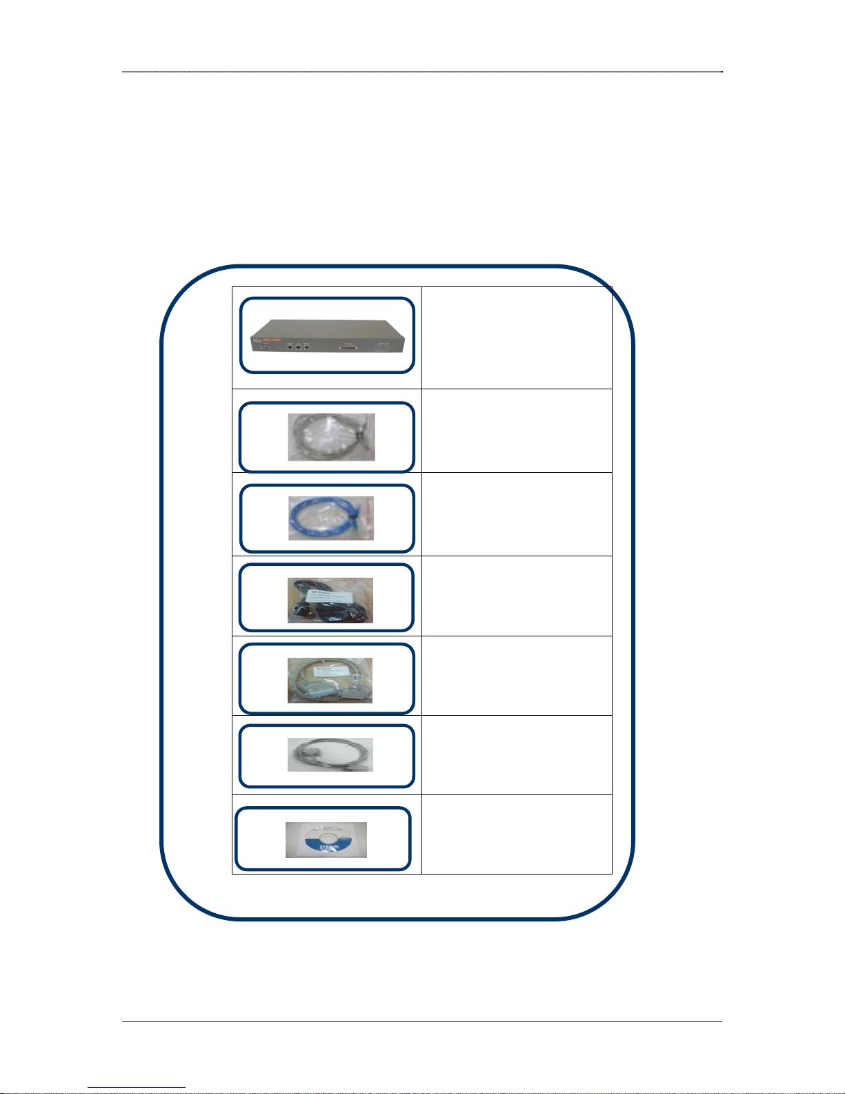
DRO-220i Package Contents
The DRO-220i package contains the following items:
• DRO-220i Router
• 3 Straight
Ethernet cables
• 1 Cross-over
Ethernet Cable
1Power cord
•
Dlink DRO-220i User Guide 6
• 1 V.35 Cable
1 Console Cable
•
• 1 User Manual CD
Product Overview
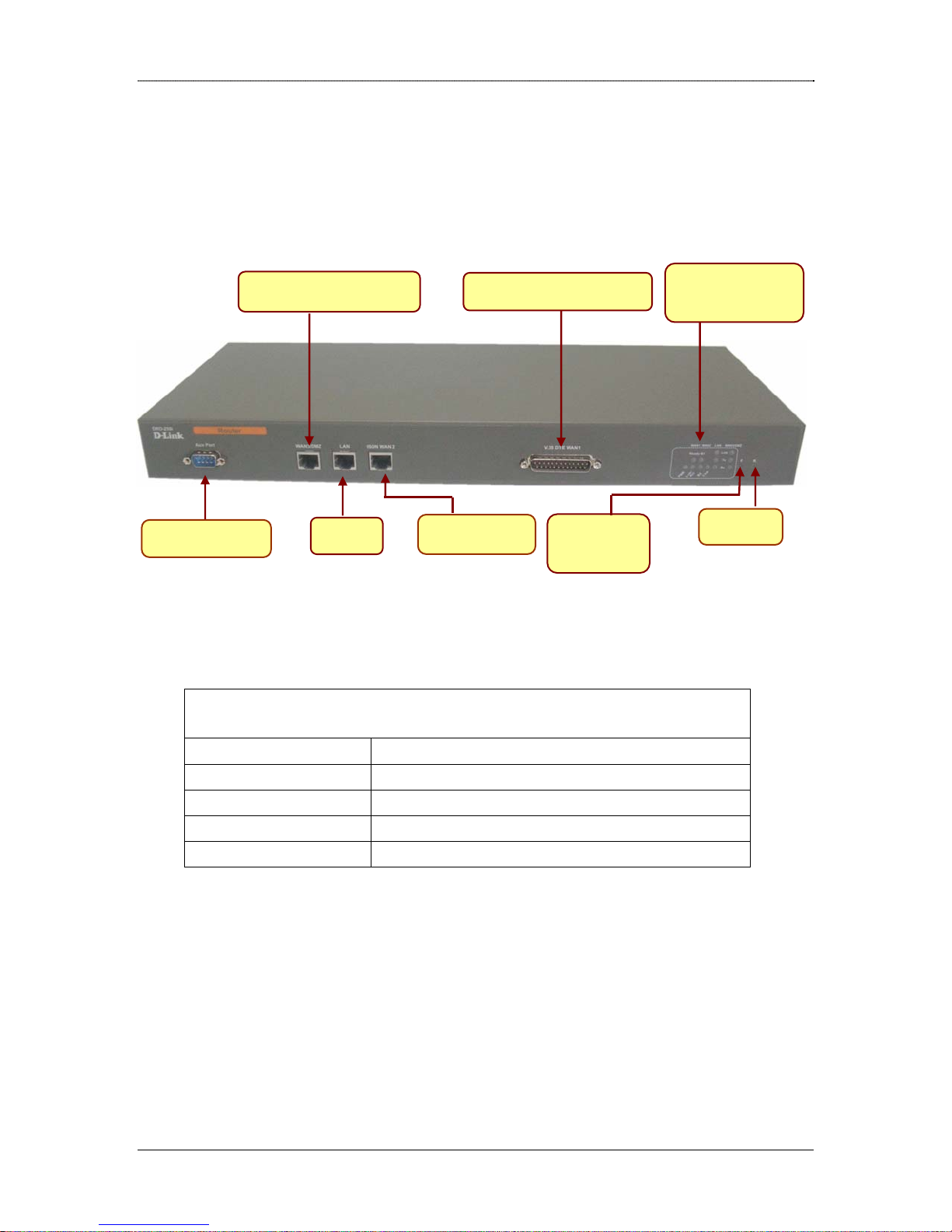
Front Panel
The front panel provides the router’s ports and reset button.
Console
WAN3/DMZ Port
LAN
V.35 DTE WAN1
ISDN Port
Factory
Reset
LED
Indication
Reset
Interfaces Description
V.35 DTE WAN1 WAN Port
LAN Ethernet 10BaseT for LAN Port (RJ-45)
WAN3/DMZ WAN3 Port / De Militarized Zone Port
ISDN WAN2 ISDN Port
Console Console Port
Dlink DRO-220i User Guide 7

Product Overview
LED Panel
The LED panel provides the power and router’s ports link status.
7 10
1 3 5 6 9 12
PWR WAN1 WAN2 LAN WAN3 SWT
2 4
8 11
F R
13 14
Number Module Status Description/Designation
1
Power On ON
OFF
2
3
WAN1
(V.35)
WAN1
(V.35)
Ready ON: Interface (Protocol) is UP
Link
/ACT
OFF: Interface (Protocol) is
DOWN
ON: Physical Link is UP
OFF: Physical Link is DOWN
4
WAN2
(ISDN)
Dlink DRO-220i User Guide 8
Blinking: There is activity
through v.35
interface
Link ON : Physical link is up
OFF : Physical link is
Down

Product Overview
5
6
7
8
9
10
WAN2
(ISDN)
WAN2
(ISDN)
B1 ON: B1 Connected
OFF: B1 Disconnected
B2 ON: B2 Connected.
OFF: B2 Disconnected
LAN Link ON : Physical link is up
OFF: Physical link is down
LAN Tx ON : Transmission Activity
on
OFF: Transmission Activity
off
LAN Rx ON: Receive Activity on
OFF: Receive Activity off
WAN3/DMZ Link ON : Physical link is up
11
12
13
14
WAN3/DMZ Tx ON : Transmission Activity
WAN3/DMZ Rx ON: Receive Activity on
SWT F Restores the factory
SWT R Hard reset for board
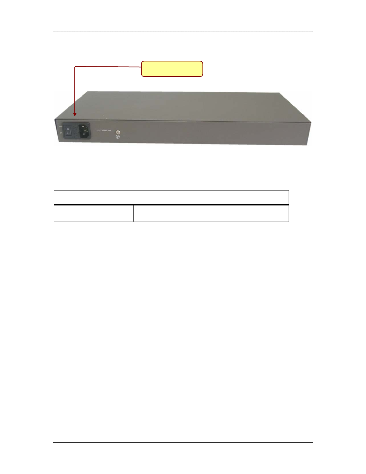
Rear Panel
The rear panel provides the router’s power socket.
OFF : Physical link is
down
on
OFF: Transmission Activity
off
OFF: Receive Activity off
Settings
Dlink DRO-220i User Guide 9
Product Overview
Power Socket
Interface Description
INPUT 85-265 VAC Input Voltage 230 VAC
Dlink DRO-220i User Guide 10

Product Overview
1.2 Software Features
The router has rich features like routing, load-balancing, auto backup, network address
translation, quality of service and remote management satisfying most of the needs of the
SMB market.
Routing
The router supports static, dynamic and policy-based routing.
Static Routing - The network administrator can manually configure the routes
according to his network topology.
RIP - The Routing Information Protocol (or RIP) enables the routes to be learnt
dynamically, avoiding cumbersome manual configuration. The router supports
both RIPv1 and RIPv2 versions.
OSPF – The Open Shortest Path First (OSPF) enables the routes to be learnt
dynamically, avoiding cumbersome manual configuration. OSPF is a link-state
protocol, which is more suitable for large networks.
Policy-Based - Policy-based routing helps to define custom policies for routing
traffic. For example, policy routes can be defined to route all HTTP traffic
through WAN1 and E-mail traffic through WAN2.
Multicast – Multicast allows a host to transmit an IP datagram to a set of hosts
that form multicast group. Every member in a multicast group that uses the same
multicast group can receive a copy of the IP datagram. Multicast supports two
protocols are Internet Group Management Protocol (IGMP) is used by IP hosts to
report their host group memberships to any immediately neighboring multicast
routers and Protocol Independent Multicast-Sparse Mode (PIM-SM) is a protocol
for efficiently routing to multicast groups that may span wide-area (and interdomain) internets.
High Availability
The Load-Balancing feature is an ideal solution for businesses requiring uninterrupted,
low cost internet connectivity. With multiple Internet connections, it effectively uses the
combined bandwidth of all the internet links resulting in a significant increase in the total
available bandwidth. Also if any Internet connection goes down, uninterrupted internet
connectivity is provided utilizing the serviceable links.
With Auto Backup feature, one of the links can function as the Primary WAN Link, and
the other as the Backup Link. When the Primary Link fails, the Backup Link will become
operational and traffic will switchover to this link. And when the Primary Link becomes
serviceable, the traffic will automatically switchback to the Primary Link.
Dlink DRO-220i User Guide 11

Product Overview
Network Address Translation (NAT)
NAT enables the router to act as an address translation agent between the Internet (public
network) and the local (or private) network. The router supports all the combinations of
NAT models like Many to Many, Many to One and One to One to provide internet access
to LAN client. And the Virtual Server (or Port Forwarding) feature enables remote access
to the Company Servers (HTTP/FTP etc) from WAN.
VoIP enables voice communication to use the same infrastructure as data in your
network; thus resulting in significant cost reductions. Session Initiation Protocol (SIP) is
widely used for VoIP calls, and does not work behind NAT. The SIP-ALG feature in the
router will ensure that SIP calls can be successfully established, even when NAT is
performed at the router. SIP-ALG overcomes the need for STUN support at VoIP end
points behind NAT.
Quality of Service
The router provides sophisticated Quality of Service (QoS) algorithm to effectively use
the available WAN bandwidth. This feature allows prioritization and bandwidth
reservation with upper ceiling for each class of service and enables optimal dynamic
utilization of bandwidth while guaranteeing highest quality voice and video services.
DHCP Server
The router provides a built-in DHCP Server/Relay for assigning network settings for the
LAN clients. The DHCP Server also supports reservation of IP Addresses for specific
hosts (based on MAC address). The DHCP Relay in the router enables LAN clients to use
a DHCP Server connected to WAN Port, by relaying the DHCP messages between the
LAN and WAN subnet.
Tools
The router supports various tools to manage and monitor the device.
Syslog - The Router can send the Syslog messages to the configured server to aid
in network administration.
NTP - The administrator can configure the system date and time manually. Or he
can use NTP feature to automatically synchronize the router’s time with specified
global time servers.
Configuration upload/download -This tool allows the administrator to download
the router configuration onto the local hard disk as a backup. The same
configuration can be later uploaded to restore the device to its original settings.
Dlink DRO-220i User Guide 12

Product Overview
Firmware Upgrade – The administrator can easily upgrade the router’s firmware
whenever a new firmware release is made available. The firmware can be
upgraded from a local/remote location in a secure manner.
SNMP – It helps to manage configurations like data networks typically include
bridges, routers, links into WANs, and end-user equipment from multiplevendors. It is easy to install, easy to use, and don’t place a great burden on the
network. It supports Message Integrity, Authentication and Encryption.
Secure Web-based Management
The product provides SSL-based secure, user friendly Web Pages to configure and
manage the device and the network. The router also supports Secure, Remote
Configuration of the device to enable easy remote monitoring and troubleshooting. In
addition, it provides Comprehensive Logging, Secure Local/Remote firmware upgrade,
Configuration Backup and Restoration.
The supported Web Browsers for router configuration are:
Internet Explorer Ver 6.0 +
Mozilla 5.0 (Release 1.5)
Netscape 8.0
Mozilla FireFox 1.0
Dlink DRO-220i User Guide 13

DHCP, DNS and Time
2 Interfaces
The router provides the following interface ports:
LAN Port - The router has one dedicated 10/100 Ethernet RJ-45 LAN port.
WAN Ports - The router has four WAN ports.
o WAN1 – V.35 can be connected to 2 Mbps Leased modem.
o WAN2 – It’s ISDN S/T port is connected to either a dial up line or a dedicated
leased line. It also supports bandwidth on demand (BOD), Auto Hang-up, Dial
on Demand (DOD). It uses MLPPP to aggregate two channels to get 128
Kbps.
o WAN3 – This port can be optionally reconfigured to operate as DMZ port.
The WAN3 interface can be used to connect to the Internet using any
broadband modem. The administrator has the following three choices for
WAN connectivity:
Static: The administrator can configure a Static IP Address assigned by the
ISP to connect to the broadband network.
Dynamic: The ISP assigns an IP Address dynamically using DHCP Protocol.
PPPoE (Point to Point link over Ethernet): This option is the most common
mode of WAN connectivity. Here the ISP assigns an IP Address dynamically
through PPPoE Protocol.
The following sections explain these interfaces and their configuration in detail.
2.1 LAN Interface
The user systems can be connected to the LAN Interface. And the administrator can
configure the router using HTTPS to this LAN Interface IP Address (i.e
https://RouterLANIP). If the administrator uses http://RouterLANIP by mistake, the
router will automatically redirect the Web Browser to use https.
L
Select Interface → LAN to configure LAN Settings as explained below.
Web UI
IP Address
Subnet Mask
Forgot LAN IP ?
Note:
Default LAN Interface IP Address is 192.168.100.254.
LAN Settings
Enter the IP address of the LAN interface.
Enter the subnet mask of the LAN interface.
Dlink DRO-220i User Guide 14

DHCP, DNS and Time
In case the administrator forgets the IP given to the LAN Port, it is possible to open the
Router’s Web Page by pressing the factory default switch and the settings will be restored
back to default settings. Type https://192.168.100.254. User name is “admin” and
password is also “admin”.
2.2 DMZ Interface
DMZ stands for Demilitarized Zone. The DMZ interface is typically used for connecting
servers that need to be accessible from the outside world, such as e-mail, web and DNS
servers.
Typically, connections from the DMZ are only permitted to the external network, and
hosts in the DMZ may not connect to the internal network. This allows the DMZ's hosts
to provide services to the external network while protecting the internal network in case
intruders compromise a host in the DMZ. For someone on the external network who
wants to illegally connect to the internal network, the DMZ is a dead end.
Select Interface → DMZ to configure DMZ Settings as explained below.
Web UI
IP Address
Subnet Mask
To add a DMZ Server in the network, the administrator can
a) Assign Private IP Addresses to the DMZ network. And configure a One-To-One
b) Or assign Private IP Addresses to the DMZ network. And configure a Virtual
c) Or assign Global IP Address to the DMZ network. And add a NAT Exception (i.e
L
NAT entry to map a Global IP Address to the Private DMZ Server IP Address.
Refer NAT Configuration for more details.
Server entry to map a Global IP Address/Port to the Private DMZ Server IP
Address/Port. Refer Virtual Server Configuration
disable NAT) between WAN and DMZ.
Note: To make the private DMZ Server accessible from the internet, use One-To-One
NAT only when multiple services are hosted by a single DMZ Server. When only one
service is provided by the DMZ Server, it is preferable to use Virtual Server feature.
This would enable you to save the number of Global IP Addresses required to expose
your DMZ services.
DMZ Settings
Enter the IP address of the DMZ interface
Enter the subnet mask of the DMZ interface
for more details.
2.3 WAN1 Interface
Dlink DRO-220i User Guide 15

DHCP, DNS and Time
This Interface is used for WAN Connectivity through an ISP. The ISP allocates and
provides a static Global IP Address for WAN connectivity. The ISP will also provide
information regarding the Default Gateway IP Address to be used for this connection.
If you have purchased multiple static Global IP Addresses from the ISP, then configure
the first IP Address as the WAN Interface IP Address. And use the rest of your static IP
Addresses for Many-To-Many or One-To-One NAT Configuration.
Select Interface → WAN1 Configure IP Settings for WAN1 Interface as explained
below.
Web UI
Protocol
IP Settings for WAN1 Interface
Select the sync protocol either cisco HDLC or sync PPP.
IP Address
Subnet Mask
Default Gateway
Enter the IP address assigned for the WAN interface
Enter the subnet mask for the IP address
Enter the default gateway address (in the same subnet).
L
Note: The default gateway field specified here will be used by Load balancing feature
to route packets through this interface.
2.4 WAN2 Interface
This Interface is used for WAN Connectivity through an ISP.
2.4.1 Mode Settings
This is to configure ISDN in either Leased or Dialup.
Select Interface → WAN2 → Mode Settings to configure ISDN in either Leased or
Dialup as explained below.
Web UI
Leased
Mode Configuration for WAN2 Interface
Click checkbox to configure ISDN in Leased mode.
Dial-up
Click checkbox to configure ISDN in Dial-up mode.
Dlink DRO-220i User Guide 16

DHCP, DNS and Time
2.4.2 Dial Up
2.4.2.1. Dial Up - Connection Settings
This is to select different types of connection settings i.e. 64kbps, 128kbps etc. If the
connection type is changed then again appropriate changes need to be done depending on
the new connection type selected.
Select Interface → WAN2 → Dial up → Connection Settings to select different types
of connection settings i.e. 64 kbps, 128 kbps etc,
Web UI
My Phone Number
Connection Settings for WAN2 Interface
“My Phone number” is user's own telephone number with an area code
included if ISDN port is directly connected to the phone socket.
Otherwise if it is connected to a PBX, then provide the MSN (phone
number) stored in the PBX. E.g.: If the area code of user is 080 and phone
number is 26788835 then enter 08026788835 in this field. It can be of
maximum 14 digits.
Layer 2 Protocol
Layer 3 Protocol
Packer
encapsulation
Connection Type
Dial On Demand
For this protocol, the parameter is set as HDLC.
For this protocol, the parameter is set as Transparent.
For this protocol, the parameter is set as Sync PPP.
Users can select among the available connection types in the dropdown
list depending on his/her requirement.
128K Dialin/Dialout-User can configure dial out and dial in 128k.
64K Dialin + 64K Dialout-User can configure first channel (B1) for dial out
and second channel (B2) for dial in.
2-64K Dialout-Users can configure two channels (B1& B2) with two
different dialout configurations.
2-64K Dialin-Users can configure two channels (B1& B2) with two
different dialin configurations.
BOD Dialout-User can configure Bandwidth on demand for dialout
configuration.
Dial on demand feature allows the system to dial automatically whenever
there is traffic on the WAN2 interface. This feature will be enabled only
when the connection type is 64kbps dial in & dialout or 2-64kbps dialout
or BOD dialout.
High Water Mark &
High Water Time
These parameters specify the conditions under which the second channel
will be activated. When the utilization of the first connected channel goes
over the High Water Mark and passes the High Water Time, the
additional channel will be activated. The link speed will then be 128kbps.
The default value for High water mark is 56 kbps and the default value
for High water
Dlink DRO-220i User Guide 17

DHCP, DNS and Time
Note: My Phone number must be filled with proper values as mentioned above to
L
support dial-in.
High Water Mark and High Water Time are enabled only when connection type
Note:
L
is BOD (Bandwidth On Demand). Default values high water mark and highwater
time are 7000 bytes and 30 seconds respectively.
2.4.2.2. Dial Up – Dial Out
This is to establish the internet connection with the ISP. It enables the user to configure
the channels with ISP configurations depending upon the connection type he chooses
from ISDN connection settings. User can configure a maximum of five different ISP
profiles and depending upon the choice he/she can configure channels with those profiles.
Profiles are independent of channels and he/she can configure any profile on any of the
channels. ADD-button enables the user to add the profile into the profiles table. APPLYbutton enables the user to apply the selected configuration on the selected channels. To
apply a particular configuration from the saved profiles user should click on View and
select the channel and click Apply. Selection of channel depends upon the connection
type the user chooses from the ISDN connections page. User can choose either B1 or B2
only when connection type is 2-64K dialout. For all other Connection types B1 channel is
selected automatically. When the Connection type is 128kbps dial out/dial in only
Channel 1(B1) will be enabled .User can see the status of two channels in the status page.
Profile table will show which profile has been selected for which channel. This page only
configures the particular channel with ISP profile. To initiate a dial go to ISDN STATUS
page and click Dial
Select Interface → WAN2 → Dial up → Dial Out to establish the internet connection
with the ISP.
Web UI
Channel Type
Dial Out Settings for WAN2 Interface
Choose either B1 or B2
Dynamic IP address
Local IP address
Unnumbered
Subnet Mask
Remote IP Address
Area Code
If this option selected, It gets IP address from the ISP dynamically
otherwise Local IP address, Subnet Mask and Remote IP Address should
be configured statically given by the ISP provider.
Fill in the fixed IP address given by the ISP provider. It is in the form of
four IP octets separated by a dot (x.x.x.x).
This interface can be configured as an Unnumbered interface
Enter the subnet mask in dotted decimal (i.e. A.B.C.D) format
Fill in the fixed IP address of the remote server given by the ISP. It is in
the form of four IP octets separated by a dot (x.x.x.x).
It provides the Area Code of the ISP. e.g. area code of user is 080 and ISP's
Dlink DRO-220i User Guide 18

DHCP, DNS and Time
area code is 022, then user should enter 22 in the area code field
Dial Prefix
Phone Number
Alternate Phone
Number
Protocol
Compression
User Name
Password
Idle Timeout
Retries
In Dial Prefix, user should enter the country code if the user is dialing to
other country, or else enter zero e.g. if user wants to dial to Singapore
then enter 0065 as dial prefix where 65 is country code of Singapore.
Enter the phone number of the ISP, excluding the Area Code and Dial
Prefix.
Enter the alternate phone number of the ISP, excluding the Area Code
and Dial Prefix. If primary phone number is busy then alternate phone
number will be dialed automatically
This will enable or disable Protocol Compression field. This should be
same as ISP settings. Before enabling or disabling this field, verify ISP
settings and then select accordingly
Enter the user name given by the ISP provider. It can be 20 characters
long
Enter the password given by the ISP provider. It can be 20 characters
long.
If there is no activity on the line then, the connection will hang-up
automatically after the time entered in Idle Timeout field in seconds.
Enter zero in this field to disable auto hang-up
Enter the number of times user wants the system to retry the dialing to
connect to ISP if it is not connected. It is a single digit number
Note: If the area code of user and the ISP is same, then enter zero in the area code
L
field.
2.4.2.3. Dial Up – Dial In
This is to establish Dial in connection and User can configure either channel 1 or channel
2 depending upon the connection type he/she selects from the ISDN connections page.
User can select Channel 1(B1) or Channel 2(B2) only when the connection type is 2-64K
Dial in. For all other connection types Channel 1(B1) will be selected automatically.
When the user clicks on the Channel 1 or Channel 2 he will get the information which he
configured previously for the particular channel.
Dial In
Select Interface → WAN2 → Dial up → Dial in → Dial In to establish Dial in
connection.
Web UI
Dial In Settings for WAN2 Interface
Dlink DRO-220i User Guide 19

DHCP, DNS and Time
Channel Type
Secure
Local IP
Unnumbered
Subnet Mask
Remote IP
Authentication
Type
Idle Timeout
Choose either B1 or B2 as channel type
When ON is selected the Dialin connections are accepted only from the
phone numbers added in the Dialin User Accounts Page. If OFF is
selected then Dialin connections will be accepted from any phone
number.
Enter the IP address to be assigned for the Dialin connection one at end. It
is in the form of four IP octets separated by a dot (x.x.x.x).
This interface can be configured as an unnumbered interface.
Enter the subnet mask in dotted decimal (i.e. A.B.C.D) format.
Enter the IP address to be assigned to the remote end for the Dialin
connection. It is in the form of four IP octets separated by a dot (x.x.x.x).
Select the PAP or CHAP depending on what the other end is using. Try
PAP/CHAP only when user is not sure what the other end is using.
If there is no activity on the line the connection gets disconnected after the
time entered in this field in seconds.
User Account
Select Interface → WAN2 → Dial up → Dial in → User Account to configure the User
Account for Dialin connections.
Web UI
User Name
User Account Settings for WAN2 Interface
Enter the user name to be given to Dialin user. It can be 20 characters
long.
Password
Phone number
Channel Type
Enter the password to be given to the Dialin user. It can be 20 characters
long.
Enter the phone number of the Dialin user including area code, for e.g. if
the Dialin user area code is 080 and phone number is 26788345 then enter
08026788345 in this field. This number is used to allow Dialin connection,
in case the SECURE option on this page is set to ON.
User can select channel type in this page so that he can restrict some user
dialing on particular channel. If he selects channel1 then username and
password will be allowed on that channel only.
If user has selected connection type 128K dialin / dialout then he can
enter a user account on channel1.
If user has selected connection type 64kdialin+64kdialout then user
should enter a user account on channel2.
If user has selected connection type 2-64kdialin then he can enter two
different phone numbers on two channels.
Dlink DRO-220i User Guide 20
 Loading...