

D-Link DPS-300, DPS-600 Quick Installation Manual
Introduction
A redundant power supply provides a low-cost, simple
solution to the equally simple yet vexing problem of internal
power supply failure, which can result in the shutdown of a
single switching device or an entire network.
With a redundant power supply connected, an integrated
detection circuit continuously monitors the switch’s internal
power supply. In the event of a power interruption, the
redundant power supply is immediately triggered so that the
switch and connected devices can continue providing
service.
This results in a more reliable network infrastructure and
protects the network from a single failure of a network
device power supply.
Description
The DPS-200, DPS-300, DPS-500, DPS-500DC, DPS-600
and DPS-700 are redundant power supply units designed to
conform to the wattage requirements of the switches being
supported. DPS-200 operates at 60 watts; DPS-300
operates at 90 watts, DPS-500/500DC at 140 watts, DPS600 at 500watts, and the DPS-700 at 589 watts.
The DPS-200, DPS-300, DPS-500, DPS-500DC, and DPS600 can connect to the master switch using a 14-pin DC
power cable. Similarly, the DPS-700 uses a 22-pin DC
power cable. A standard, three-pronged AC power cable
connects the redundant power supply to the main power
source.
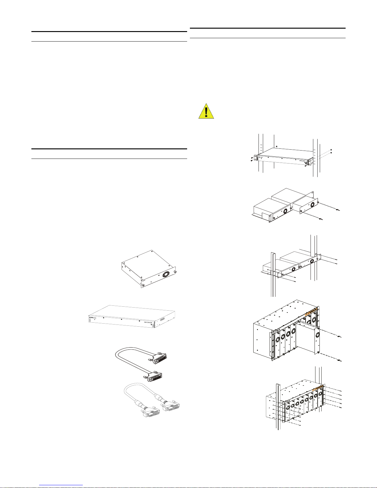
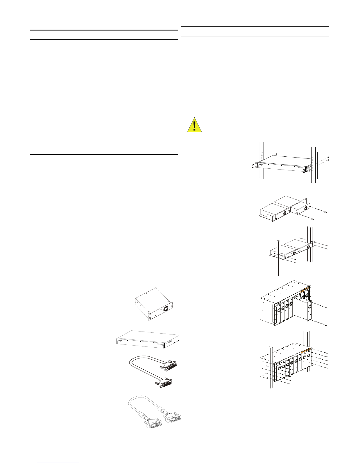
Single RPS (DPS-200/DPS-300
/DPS-500/DPS-500DC)
Single RPS (DPS600/700)
14-pin DC power cable
22-pin DC power cable
Installation of the RPS
The single RPS DPS-200, 300, 500, and 500DC can be
installed to the standard rack via the RPS rack DPS-800
and DPS-900. DPS-900 is a standard-size rack mount (5U
in height) designed to hold up to 8 redundant power
supplies. The DPS-800 is also a standard-size rack mount
(1.25U in height) designed to hold up to 2 redundant power
supplies. Installed RPS units can be DPS-200s, DPS-300s,
DPS-500s, DPS-500DCs, or a combination of the above.
NOTE: The DPS-500DC can only be
inserted into a DPS-800
Installing a DPS600/700 in a standard
electronics rack
Inserting a single
RPS into a DPS-800
RPS rack
Installing a DPS-800 in a
standard electronics rack
Inserting a single
RPS into a DPS-900
RPS rack
Installing a DPS-900 in a
standard electronics
rack
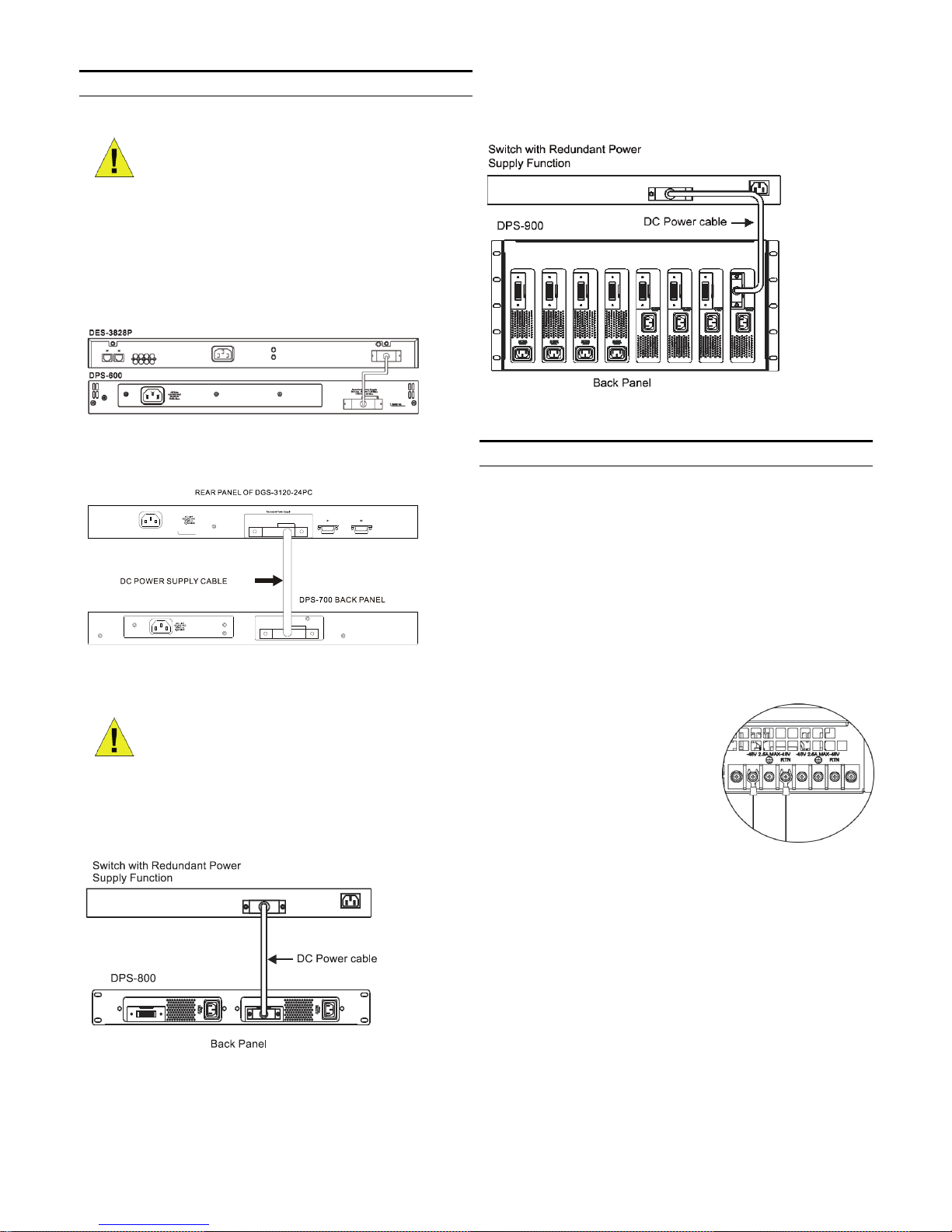
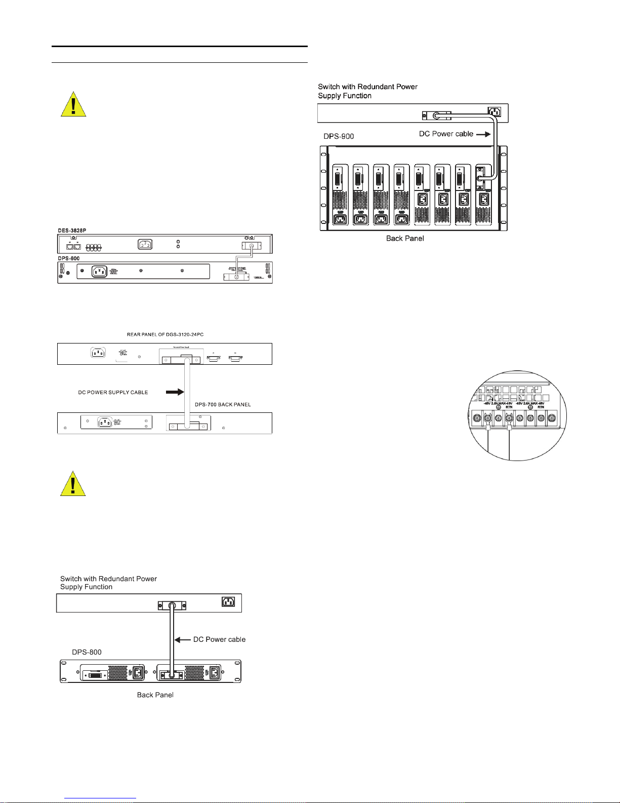
Switch Connection
Caution: The redundant power supply should
be disconnected from its power source before
connecting to the switch. Directly connecting
a powered RPS to the switch may cause
damage to the switch’s internal power supply.
Insert one end of the DC power cable into the receptacle on
the switch and the other end into the redundant power
supply.
Connecting a DPS-600 to a switch
Connecting a DPS-700 to a switch
Caution: Do not connect the DPS-700 to the
switch using the 14-pin DC power cable. The
equipment may be damaged if using this
cable instead of the correct 22-pin DC power
cable.
Connecting a single RPS in a DPS-800 rack to a switch
Connecting a single RPS in a DPS-900 rack to a switch
Power Connection
Connecting AC Power (DPS-200/300/500/600/700)
Using a standard AC power cable, connect the redundant
power supply to the main AC power source. A green LED
on the front of the DPS-200/DPS-300/DPS-500/DPS-600
will glow to indicate a successful connection.
Connecting DC Power (DPS-500DC)
1. Firmly attach the DC power source to the negative and
positive contacts on the wiring assembly.
The negative pole (-)
connects to the -48V contact.
The positive pole (+)
connects to the -48V RTN
contact.
If available, an earth ground
may be connected to the
center contact post.
2. Tighten the contact screws to secure the connection.
No change in switch configuration is necessary when
connecting to the RPS.
inführung
Ein redundantes Netzteil stellt eine kostengünstige und
einfache Lösung dar, für den Fall, dass das interne Netzteil
einer aktiven Komponente ausfallen sollte, denn dadurch
kann ein einzelnes Gerät oder das komplette
Netzwerksystem lahmgelegt werden.
Sobald das redundante Netzteil angeschlossen ist,
überwacht ein integrierter Sensor permanent das interne
Netzteil des Switches. Im Falle einer Stromunterbrechung
wird das redundante Netzteil sofort aktiviert, so dass der
Switch und die angeschlossenen Geräte unterbrechungsfrei
weiterarbeiten.
So wird die Verfügbarkeit der Netzwerkinfrastruktur erhöht
und vor dem Ausfall eines einzelnen Netzteiles geschützt.
Beschreibung
DPS-200, DPS-300, DPS-500, DPS-500DC and DPS-600
sind externe redundante Netzteile, die perfekt an die
Leistungsanfoderungen der entsprechenden Switches
angepasst sind. Das DPS-200 liefert 60 Watt, DPS-300 90
Watt, DPS-500/500DC 140 Watt und DPS-600 ist für 500
Watt ausgelegt.
Das DPS-200, DPS-300, DPS-500, DPS-500DC und DPS600 kann mithilfe eines 14-Pin Gleichstromkabels an den
Master Switch angeschlossen werden. Ähnlich verwendet
das DPS-700 ein 22-Pin Gleichstromkabel. Ein
standardmäßiger Schuko-Stecker verbindet die redundante
Stromversorgung mit der Hauptstromquelle.
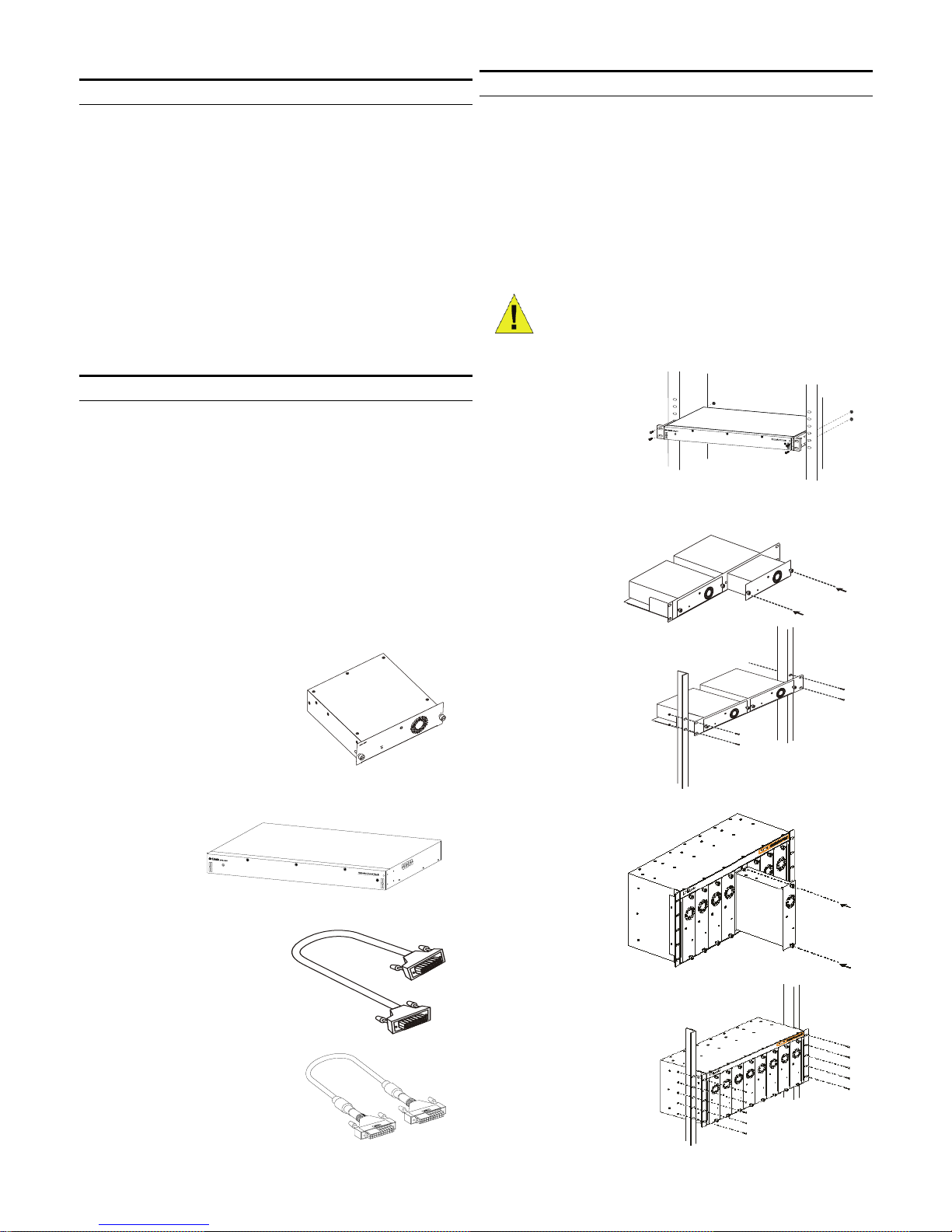
Redundantes Einzelnetzteil
(DPS-200/DPS-300 /DPS500/DPS-500DC)
Redundantes
Einzelnetzteil
(DPS-600/700)
14-Pin Gleichstromkabel
22-Pin Gleichstromkabel
Installation
Die redundanten Netzteile DPS-200, -300, -500 und 500DC können über die Einbaurahmen DPS-800 und DPS900 in einen 19-Zollschrank eingebaut werden. Der DPS900 belegt 5 Höheneinheiten im 19-Zoll System und kann
bis zu 8 externe redundante Netzteile aufnehmen. Der 19Zoll Einbaurahmen DPS-800 belegt 1,25 Höheneinheiten
und kann bis zu 2 redundante Netzteile aufnehmen. Es
können redundante Netzteile der Modelle DPS-200, DPS300, DPS-500, DPS-500DC oder eine beliebige
Kombination installiert werden.
Hinweis: Das Modell DPS-500DC kann nur
in einen DPS-800 eingesetzt werden.
Installation eines DPS600/700 in ein
Standard-Rack
Montage eines
redundanten
Netzteiles in den
DPS-800
Einbaurahmen
Einbau des DPS-800 in
einem 19-Zoll Schrank
Montage eines
redundanten
Netzteiles in den
DPS-900
Einbaurahmen
Einbau des DPS-900 in
einem 19-Zoll Schrank
Switch-Verbindung
Warnhinweis: Das redundante Netzteil sollte von
seiner Stromversorgung getrennt sein, wenn es am
Switch angeschlossen wird. Ein eingeschaltetes
redundantes Netzteil an einem Switch
anzuschliessen, kann zu Schäden am internen
Netzteil des Switches führen.
Stecken Sie ein Ende des 14poligen DC Stromkabels in die
dafür vorgesehene Buchse auf der Rückseite des Switches
und das andere Ende in die entsprechende Buchse des
redundanten Netzteiles.
Anschluss eines DPS-600 an einem Switch
Anschluss eines DPS-700 an einen Switch
Warnhinweis: Verwenden Sie nicht das 14-
Pin Gleichstromkabel für den Anschluss an
den DPS-700. Das könnte das Gerät
beschädigen. Verwenden Sie stattdessen das
22-Pin Gleichstromkabel.
Anschuss eines redundanten Netzteiles in einem DPS800 Einbaurahmen an einen Switch
Anschuss eines redundanten Netzteiles in einem DPS900 Einbaurahmen an einen Switch
Mit einem Standard Wechselstrom Kaltgerätekabel wird das
redundante Netzteil mit der Steckdose des Stromnetzes
verbunden. Eine grün leuchtende LED-Anzeige auf der
Vorderseite des DPS-200/DPS-300/DPS-500/DPS-600
zeigt den erfolgreichen Anschluss an.
Anschluss des Gleichstrom-Netzteiles (DPS-500DC)
1. Schrauben Sie die negative und die positive Kabelader
an der Kontaktleiste fest.
Der negative Pol (-) gehört
zum -48V Kontakt.
Der positive Pol (+) gehört
zum -48V RTN Kontakt.
Falls vorhanden, kann eine
Erdung am Kontakt in der
Mitte vorgenommen werden.
2. Ziehen Sie die Kontaktschrauben fest an, um für eine
sichere Verbindung zu sorgen.
Beim Anschluss eines redundanten Netzteiles muss an der
Switchkonfiguration nichts geändert werden.
Introduction
Une alimentation redondante RPS fournit une solution peu
coûteuse et simple de gestion des problèmes d'échec de
l'alimentation électrique interne d’un appareil, qui peut avoir
comme conséquence l'arrêt d'un dispositif simple de
commutation ou d'un réseau entier.
Relié à l’alimentation redondante RPS, un circuit de
détection intégré surveille en permanence l'alimentation
interne du commutateur. En cas d’interruption de puissance,
l'alimentation redondante est immédiatement déclenchée
de sorte que le commutateur et les dispositifs reliés
puissent assurer une continuité de service.
L’alimentation redondante RPS assure une infrastructure
réseau plus fiable et protège cette dernière d’une simple
coupure de l'alimentation électrique d’un produit.
Description
Les RPS DPS-200, DPS-300, DPS-500, DPS-500DC et
DPS-600 sont les alimentations redondantes conçues pour
répondre aux exigences de puissance en watts des
commutateurs répondants aux mêmes caractéristiques
électriques.
Le DPS-200 fonctionne à 60 watts, le DPS-300 fonctionne
à 90 watts, les DPS-500/500DC eux à 140 watts, et DPS600 à 500 watts.
Vous pouvez connecter les périphériques DPS-200, DPS300, DPS-500, DPS-500DC et DPS-600 au commutateur
principal à l’aide d’un câble d’alimentation CC à 14 broches.
De même, le DPS-700 utilise un câble d’alimentation CC à
22 broches. Un câble d’alimentation CA triphasé standard
permet de connecter l’alimentation redondante à la source
d’alimentation principale. Bloc d'alimentation redondant
RPS simple (DPS-600/700)
.
RPS Simple (DPS-200/DPS-300 /DPS500/DPS-500DC)
RPS Simple (DPS-600/700)
Câble d’alimentation CC à 14 broches.
Câble d’alimentation CC à 22
broches
Installation des RPS
Les RPS simples DPS-200, 300, 500, et 500DC peuvent
être installées dans une armoire standard par
l'intermédiaire d’un rack DPS-800 ou DPS-900. Le DPS900 est un rack de support de taille- standard (5U) conçu
pour supporter 8 alimentations RPS.
Le DPS-800 est également un support de rack de taille
standard (1.25U ) conçu pour supporter 2 alimentations
RPS.
Les unités installées RPS peuvent être des DPS-200s,
DPS-300s, DPS-500s, DPS-500DCs, ou une combinaison
de ces derniers.
NOTE: le DPS-500DC ne peut s’insérer
que dans un châssis DPS-800
Installation d’un DPS600/700 dans un rack
électronique standard
Insertion d’un RPS dans
un Rack DPS-800.
Installation d‘un DPS-800 dans un
rack standard.
Insertion d’un RPS dans
un rack DPS-900.
Installation d‘un DPS-900
dans un rack standard
 Loading...