

Page 1
Page 2

Table of Contents
Table of Contents
PACKAGE CONTENTS .......................................................................................... 1
SYSTEM REQUIREMENTS..................................................................................... 1
FEATURES.......................................................................................................... 2
HARDWARE OVERVIEW .................................................................................... 3
LED Indicators.............................................................................................. 4
INSTALLATI ON.................................................................................................... 5
BEFORE YOU BEGIN............................................................................................ 5
WIRELESS INSTALLATION CONSIDERATIONS.......................................................... 6
CONNECT TO CABLE/DSL/SATELLITE MODEM ...................................................... 7
CONFIGURATION................................................................................................ 8
Web-based Configuration Utility................................................................... 8
CONFIGURE INTERNET CONNECTION - SETUP WIZARD.......................................... 9
Internet Connection Setup Wizard............................................................. 10
CONFIGURE INTERNET CONNECTION – MANUAL SETUP ...................................... 17
Dynamic IP Address................................................................................... 18
Static IP Address........................................................................................ 19
PPPoE........................................................................................................ 20
PPTP.......................................................................................................... 22
L2TP........................................................................................................... 24
BigPond...................................................................................................... 25
PPTP Russia.............................................................................................. 26
PPPoE Russia............................................................................................ 27
CONFIGURE WIRELESS CONNECTION - SETUP WIZARD....................................... 28
Wireless Connection Setup Wizard............................................................ 29
WIRELESS CONNECTION – MANUAL SETUP........................................................ 32
Wireless Network Settings ......................................................................... 33
Wi-Fi Protected Setup.................................................................................34
Wireless Security - WEP ............................................................................35
Wireless Security – WPA/EAP.................................................................... 36
Wireless Security – WPA/PSK.................................................................... 37
LAN SETUP...................................................................................................... 38
Router IP Settings.......................................................................................39
LAN DHCP Server Settings........................................................................40
PRINTER SETUP................................................................................................41
Printer Setup Wizard...................................................................................41
TIME AND DATE .................................................................................................44
PARENTAL CONTROL..........................................................................................45
ADVANCED SETUP.............................................................................................46
Port Forwarding..........................................................................................47
Application Rules........................................................................................48
Access Control............................................................................................49
Firewall & DMZ...........................................................................................50
Advanced Wireless..................................................................................... 51
Advanced Network......................................................................................53
Routing .......................................................................................................54
QoS Engine ................................................................................................55
Guest Zone................................................................................................. 56
Traffic Management.................................................................................... 58
MAINTENANCE...................................................................................................59
Device Administration................................................................................. 59
Save and Restore.......................................................................................60
Firmware Update........................................................................................61
DDNS Setting .............................................................................................62
2
Page 3

Table of Contents
System Check ............................................................................................ 63
Schedules................................................................................................... 64
Log Settings ............................................................................................... 65
STATUS ............................................................................................................ 66
Device Information ..................................................................................... 66
Log.............................................................................................................. 67
Statistics..................................................................................................... 68
Active Session............................................................................................ 69
Wireless Client List..................................................................................... 70
TECHNICAL SPECIFICATIONS........................................................................ 71
3
Page 4
Section 1 - Product Overview
Package Contents
• DIR-320 Wireless Broadband Router
• Power Adapter
• CD-ROM with User Manual
• One straight-through Ethernet cable
• One Quick Installation Guide
IMPORTANT: Using a power supply with a different voltage rating than the one included
with the DIR-320 will cause damage and void the warranty for this product.
System Requirement s
• Broadband Internet connection via Cable or ADSL modem
• Computer with:
• 200MHz Processor
• 64MB Memory
• CD-ROM Drive
• Ethernet Adapter with TCP/IP Protocol Installed
• Internet Explorer v6 or later, FireFox v1.5
• Computer with Windows 2000, Windows XP, or Windows Vista
D-Link DIR-320 User Manual
1
Page 5

Section 1 - Product Overview
Features
• Faster Wireless Networking - The DIR-320 provides up to 54Mbps* wireless connection with other 802.11g wireless clients. This capability
allows users to participate in real-time activities online, such as video streaming, online gaming, and real-time audio. The performance of this
802.11g wireless router gives you the freedom of wireless networking at speeds x faster than 802.11b.
• Compatible with 802.11b and 802.11g Devices - The DIR-320 is still fully compatible with the IEEE 80 2.11b standard, so it can connect
with existing 802.11b PCI, USB and Cardbus adapters.
• Advanced Firewall Features - The Web-based user interface displays a number of advanced network management features including:
• Content Filtering - Easily applied content filtering based on MAC Address, URL, and/or Domain Name.
• Filter Scheduling - These filters can be scheduled to be active on certain days or for a duration of hours or minutes.
• Secure Multiple/Concurrent Sessions - The DIR-320 can pass through VPN sessions. It supports multiple and concurrent IPSec
and PPTP sessions, so users behind the DIR-320 can securely access corporate networks.
• User-friendly Setup Wizard - Through its easy-to-use Web-based user interface, the DIR-320 lets you control what information is
accessible to those on the wireless network, whether from the Internet or from your company’s server. Configure your router to your specific
settings within minutes.
• Print Server – Built-in printer server ideal for network printer sharing. Connect printer directly to the router via USB port. The Print Server
Setup Wizard with automatic detection of most USB capable printer makes short work of printer setup for the network.
*Maximum wireless signal rate derived from IEEE Standard 802.11g specifications. Actual data throughput will vary. Network condition s and environmental factors,
including volume of network traffic, building materials and construction, and network overhead, lower actual data throughput rate. Environmental conditions will adversely
affect wireless signal range.
D-Link DIR-320 User Manual
2
Page 6
Section 1 - Product Overview
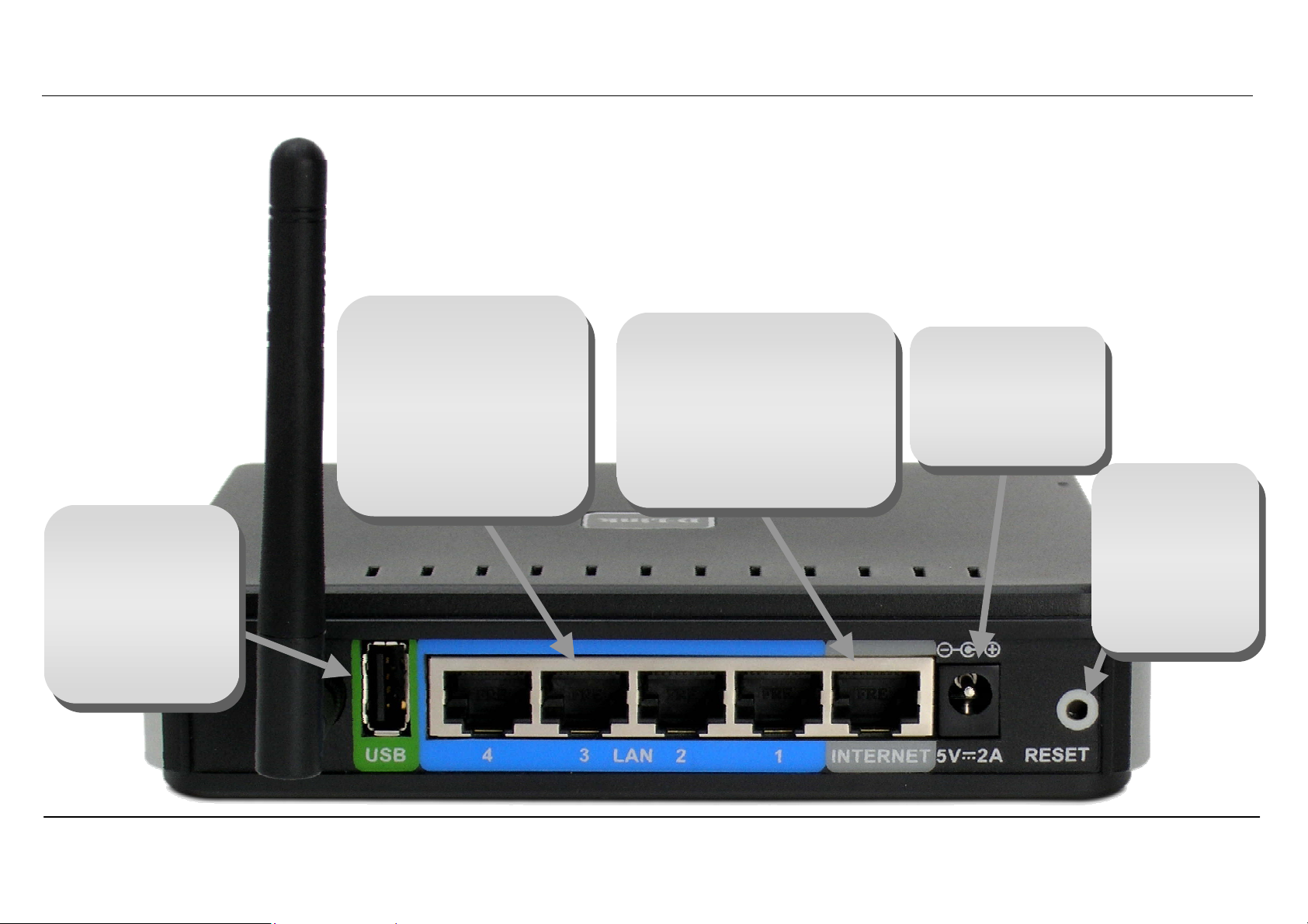
USB Port
Connect to a
single computer or
network printer.
Use included USB
cable to make
connection.
Hardware Overview
LAN Ports
Use the Ethernet LAN
ports to connect the
Router to computers or
network devices on an
Ethernet LAN. Use
Ethernet cables for all
LAN connections.
Internet Port
The auto MID/MDIX Internet
(WAN) port is used for
connection to a broadband
cable or ADSL modem. Use
the included Ethernet cable
for the connection to a
broadband device.
Power Insert
Use the adapter
shipped with the
Router to connect
to power source
Reset Button
To manually
reset, depress
button with the
power on for at
least seven
seconds
D-Link DIR-320 User Manual
3
Page 7
Section 1 - Product Overview
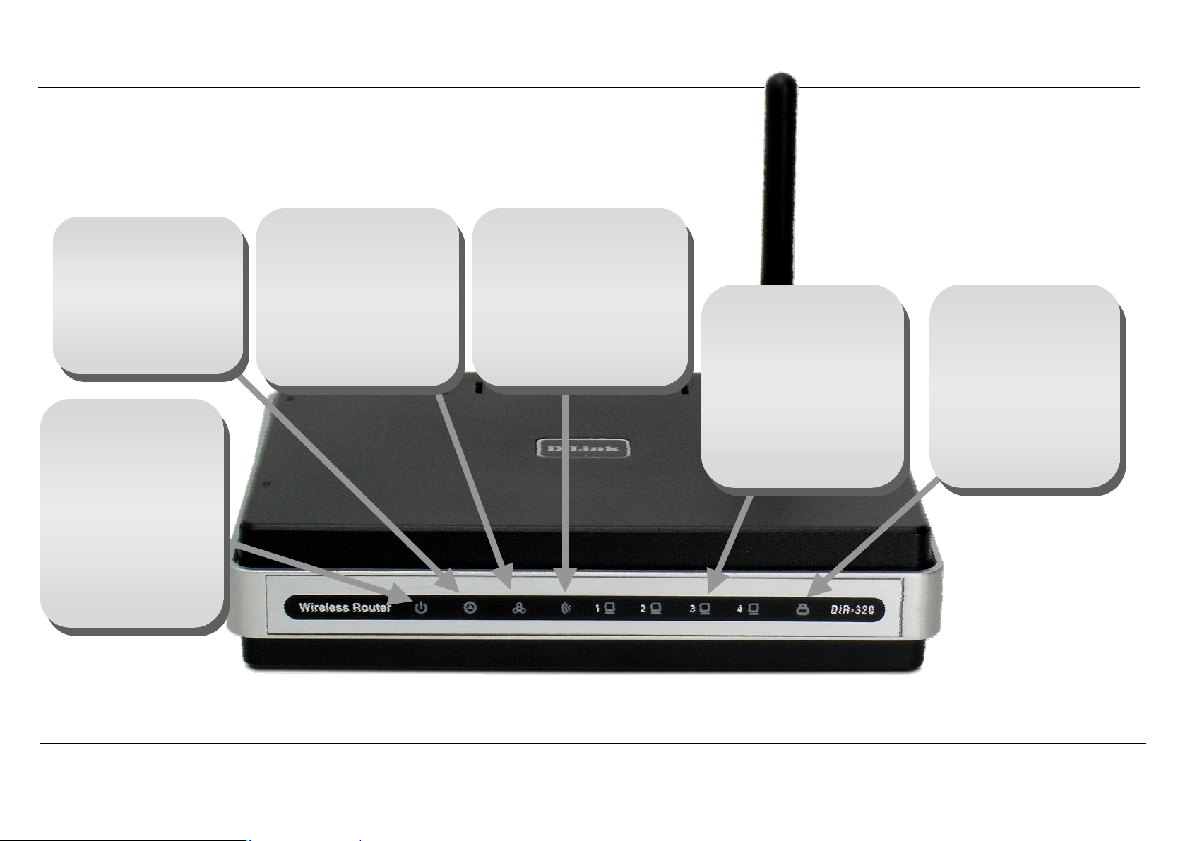
A
Status
Blinking green light
indicates normal
function. Dark
indicator means the
system has failed.
Power
Steady green light
indicates the unit is
powered on. When
the device is
powered off this
remains dark. A red
colored Power LED
indicates system
WAN (Internet)
A steady green light
indicates a valid WAN
connection. A blinking
green light indicates
activity on the WAN
(Internet) interface.
LED Indicators
WLAN
Steady green light
indicates a wireless
connection. A blinking
green light indicates
activity on the Wireless
LAN interface.
LAN
A steady green light
indicates a valid link
on startup. This light
will blink when there
is activity currently
passing through the
Ethernet port.
USB (Printer Port)
steady green light
indicates a valid
link. This light will
blink when there is
activity currently
passing through the
USB port.
D-Link DIR-320 User Manual
4
Page 8

Section 2 – Installation
Installation
This section will walk you through the installation process. Placement of the Wireless Broadband Router is very important. Do not place the router in
an enclosed area such as a closet, cabinet, or in the attic or garage. Place the Wireless Broadband Router in a location where it can be easily
connected to Ethernet devices, the telephone line as well as to a power source.
Before You Begin
Please read and make sure you understand all the prerequisites for proper installation of your new router. Have all the necessary information and
equipment on hand before beginning the installation.
Operating Systems
The DIR-320 uses an HTML-based web interface for setup and management. The web configuration manager may be accessed using any
operating system capable of running web browser software, including Windows 98 SE, Windows ME, Windows 2000, Windows XP, and Windows
Vista.
Web Browser
Any common web browser can be used to configure the router using the web configuration management software. The web browser must have
JavaScript enabled. JavaScript is enabled by default on many browsers. Make sure JavaScript has not been disabled by other software (such as
virus protection or web user security packages) that may be running on your computer.
Ethernet Port (NIC Adapter)
Any computer that uses the router must be able to connect to it through the Ethernet port on the router. Most notebook computers and fully
assembled desktop computers are now sold with an Ethernet port already installed. If your computer does not have an Ethernet port, you must
install an Ethernet NIC adapter before you can use the router.
Wireless LAN
Computers using the Wireless network can access the Internet or use the embedded 802.1g wireless access point. Wireless workstations must
have an 802.1g or 802.1b wireless network card installed to use the Wireless Broadband Router. In addition the workst ations must be configured to
operate on the same channel and SSID as the Wireless Broadband Router. If wireless security is used, the wireless workstations must be properly
configured for the security settings used.
D-Link DIR-320 User Manual
5
Page 9

Section 2 – Installation
Wireless Installation Considerations
The D-Link wireless router lets you access your network using a wireless connection from virtually anywhere within the operating range of your
wireless network. Keep in mind, however, that the number, thickness and location of walls, ceilings, or other objects that the wireless signals must
pass through, may limit the range. Typical ranges vary depending on the types of materials and background RF (radio frequency) noise in your
home or business. The key to maximizing wireless range is to follow these basic guidelines:
1. Keep the number of walls and ceilings between the D-Link router and other network devices to a minimum – each wall or ceiling can
reduce your adapter's range from 3-90 feet (1-30 meters.) Position your devices so that the number of walls or ceilings is minimized.
2. Be aware of the direct line between network devices. A wall that is 1.5 feet thick (.5 meters), at a 45-degree angle appears to be almost 3
feet (1 meter) thick. At a 2-degree angle it looks over 42 feet (14 meters) thick! Position devices so that the signal will travel straight
through a wall or ceiling (instead of at an angle) for better reception.
3. Building Materials make a difference. A solid metal door or aluminum studs may have a negative effect on range. Try to position access
points, wireless routers, and computers so that the signal passes through drywall or open doorways. Materials and objects such as glass,
steel, metal, walls with insulation, water (fish tanks), mirrors, file cabinets, brick, and concrete will degrade your wireless signal.
4. Keep your product away (at least 3-6 feet or 1-2 meters) from electrical devices or appliances that generate RF noise.
5.
If you are using 2.4GHz cordless phones or X-10 (wireless products such as ceiling fans, lights, and home security systems), your
wireless connection may degrade dramatically or drop completely. Make sure your 2.4GHz phone base is as far away from your wireless
devices as possible. The base transmits a signal even if the phone in not in use.
D-Link DIR-320 User Manual
6
Page 10

Section 2 – Installation
Connect to Cable/DSL/Satellite Modem
If you are connecting the router to a cable/DSL/satellite modem, please follow the steps below:
1. Place the router in an open and central location. Do not plug the power adapter into the router.
2. Turn the power off on your modem. If there is no on/off switch, then unplug the modem's power adapter. Shut down your computer.
3. Unplug the Ethernet cable (that connects your computer to your modem) from your computer and place it into the port labeled “Internet”
on the router.
4. Plug an Ethernet cable into one of the four LAN ports on the router. Plug the other end into the Ethernet port on your computer.
5. Turn on or plug in your modem. Wait for the modem to boot (about 30 seconds).
6. Plug the power adapter to the router and connect to an outlet or power strip. Wait about 30 seconds for the router to boot.
7. Turn on your computer.
8. Verify the link light s on the router. The power light, WAN light, and the LAN light (the port that your computer is plugged into) should be lit.
If not, make sure your computer, modem, and router are powered on and verify the cable connections are correct.
9. Use the instructions found in this manual to complete the configuration of the router.
D-Link DIR-320 User Manual
7
Page 11
Section 3 – Configuration
Configuration
This section will show you how to set up and configure your new D-Link router using the Web-based configuration utility.
Web-based Configuration Utility
Connect to the Router
To configure the WAN connection used by the router it is first necessary to communicate with the router through its management interface, which is
HTML-based and can be accessed using a web browser. The easiest way to make sure your computer has the correct IP settings is to configure it
to use the DHCP server in the router. The next section describes how to change the IP configuration for a computer running a Windows operating
system to be a DHCP client.
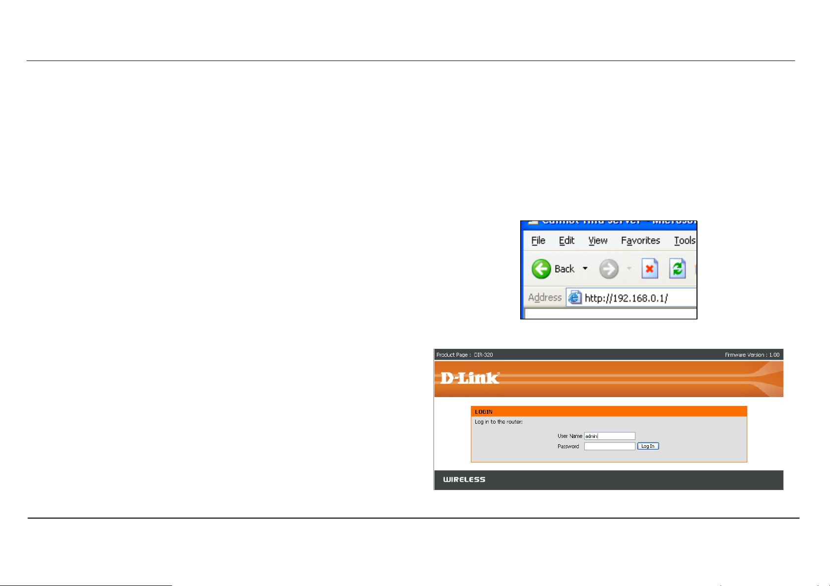
To access the configuration utility, open a web-browser such as Internet
Explorer and enter the IP address of the router (192.168.0.1).
Type “admin” for the User Name in the entry field. If this is the first time
configuring the router, leave the Password field blank, there is no default
password.
If you get a Page Cannot be Displayed error, please refer to the
Troubleshooting section for assistance.
D-Link DIR-320 User Manual
8
Page 12
Section 3 – Configuration
Configure Internet Connection - Setup Wizard
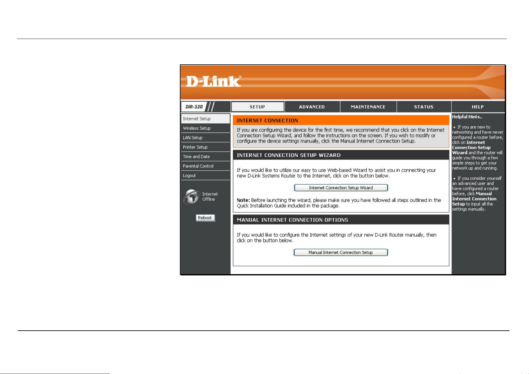
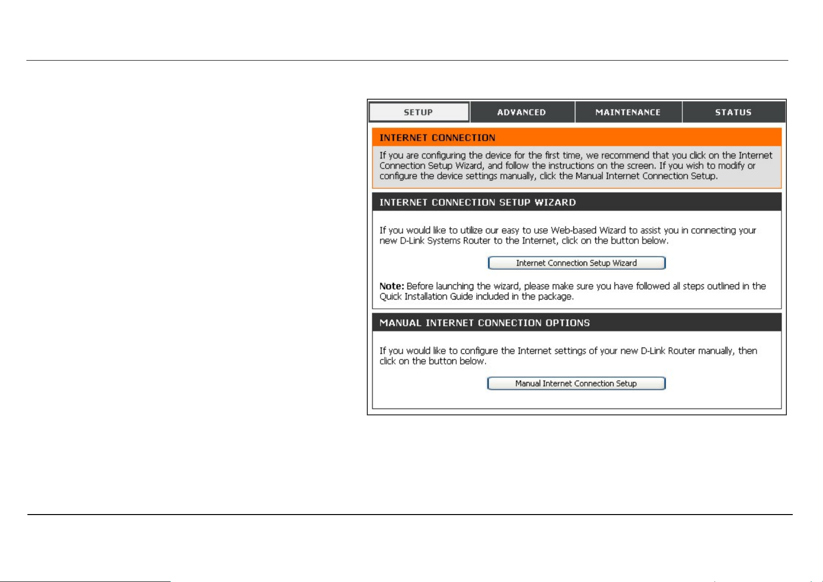
When you successfully connect to the web
manager, the main Internet Connection
menu displays two options for configuring the
Internet connection.
Click on he Internet Connection Setup
Wizard to quickly configure the Internet
connection. The Setup Wizard procedure is
described in the pages following this one.
To configure the connection in more detail,
click on the Manual Internet Connection Setup
button. Manual Internet connection setup is
described in Internet Connection - Configure
Internet Connection – Manual Setup on page
17 below.
D-Link DIR-320 User Manual
9
Page 13
Section 3 – Configuration
Internet Connection Setup Wizard
Use the Internet Connection Setup Wizard to quickly configure the Internet connection.
Setup Wizard
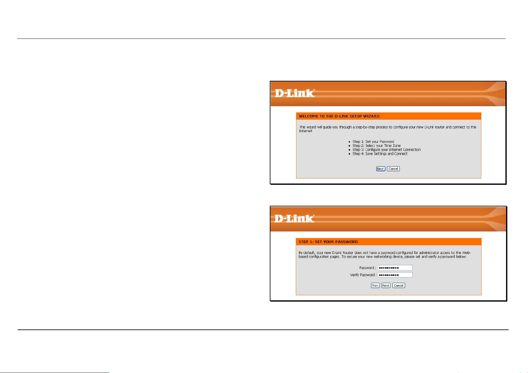
Click the Internet Connection Setup Wizard button and follow the
instructions in the menus that appear.
The initial window summarizes the setup process. These steps are as
follows:
1. Set the new password.
2. Select the time zone.
3. Configure the connection to the Internet.
4. Save settings and reboot the router.
Click the Next button to proceed. You may stop using the Setup Wizard at
any time by clicking the Cancel button. I
Change the administrator account password, enter a new password in the
first Password entry field, re-type it exactly as before in the Verify
Password field, and click Next. If you wish to return to the previous
window during the setup process, click the Prev button.
D-Link DIR-320 User Manual
10
Page 14
Section 3 – Configuration
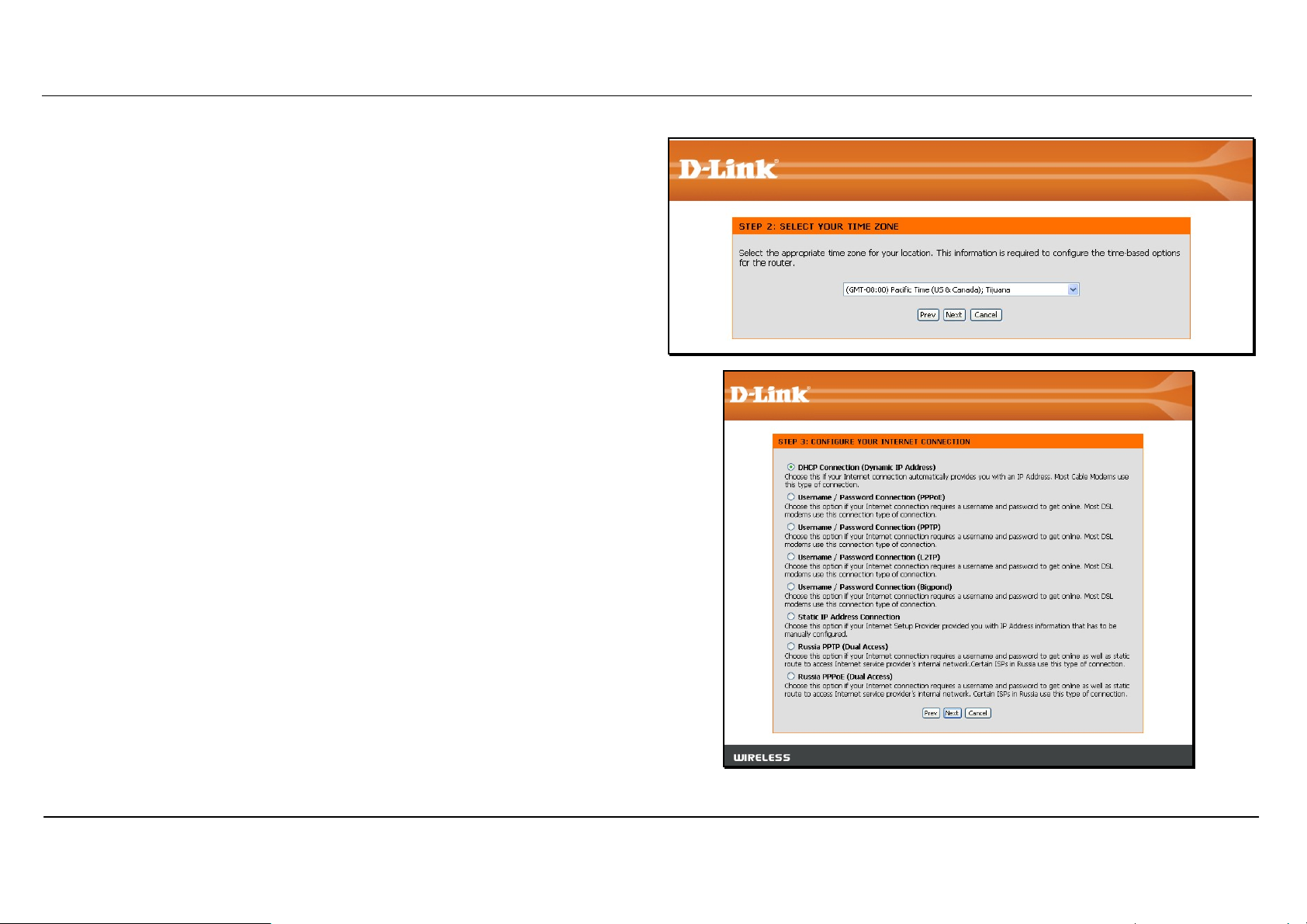
Choose the time zone you are in from the pull-down menu and click Next.
This sets the system time used for the router. If you wish to return to the
previous window during the setup process, click the Prev button.
Select the Internet Connection Type used for the Internet connection. Your
ISP has given this information to you. The connection types available are
DHCP (Dynamic IP Address), Username/Password (PPPoE),
Username/Password (PPTP), Username/Password (L2TP),
Username/Password (Bigpond), Static IP Address Connection,
Russia PPTP (Dual Access) and Russia PPPoE (Dual Access). Each
connection type has different settings that are configured in the next menu
Select the Connection Type specific to your service and click Next.
Follow the instructions below for the type of connection you have
selected.
D-Link DIR-320 User Manual
11
Page 15
Section 3 – Configuration
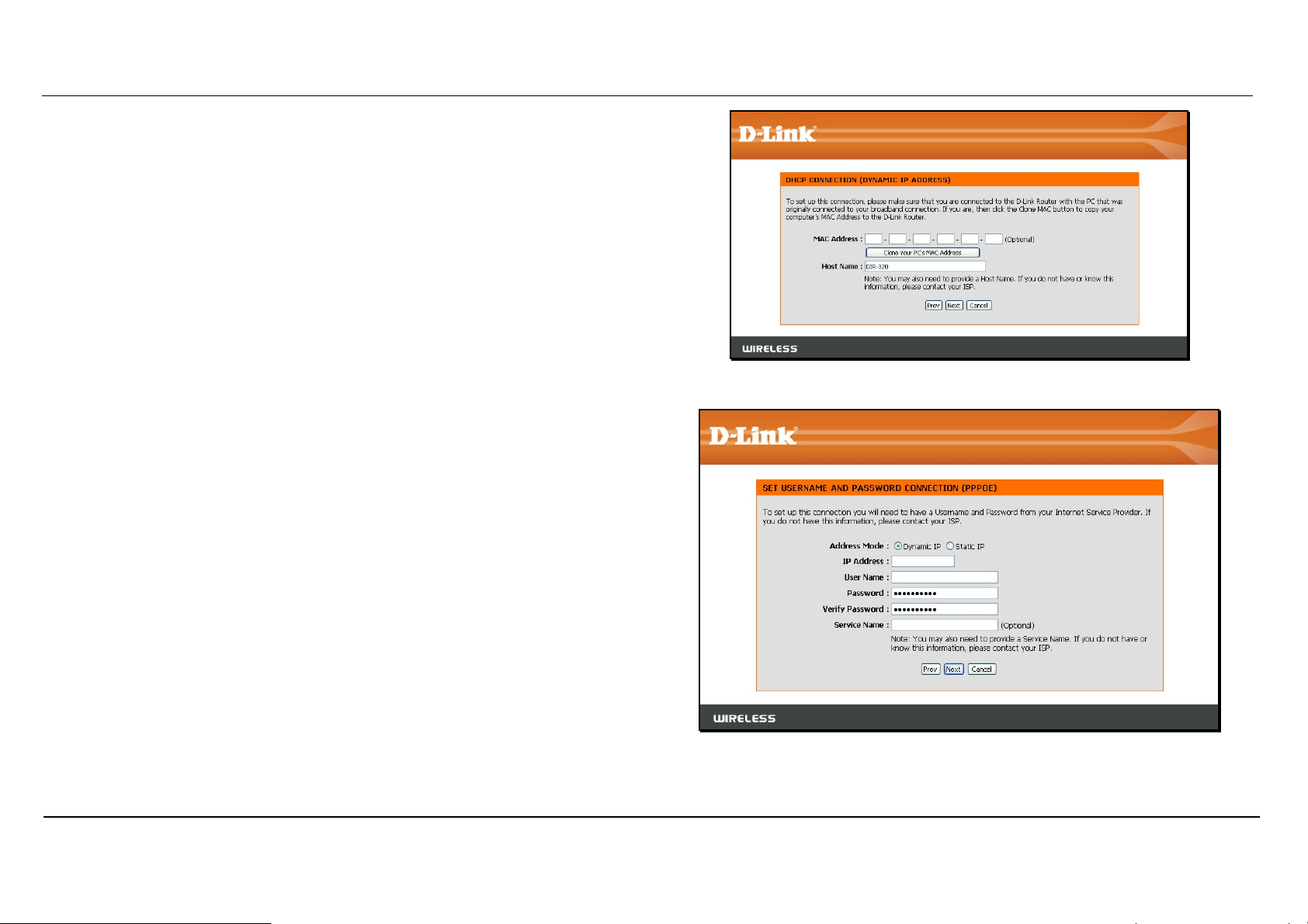
DHCP (Dynamic IP Address) - For Dynamic IP Address connections,
you may want to copy the MAC address of your Ethernet adapter to the
router. Some ISPs use the unique MAC address of your computer’s
Ethernet adapter for identification and for IP address assignment (DHCP)
when you first access their network. This can prevent the router (which
has a different MAC address) from being allowed access to the ISP’s
network (and the Internet). To clone the MAC address of your computer’s
Ethernet adapter, click the Clone MAC Address button. Click Next to
continue.
Username/Password (PPPoE) - For PPPoE connections, select the
Address Mode Dynamic IP or Static IP, type in the Username and
Password used to identify and verify your account to the ISP. Retype the
password again and if necessary, type a Service Name or domain name.
For Static IP address mode, type the IP Address assigned to your
account. Your ISP should provide this IP address along with other account
information. Click Next to continue.
D-Link DIR-320 User Manual
12
Page 16
Section 3 – Configuration
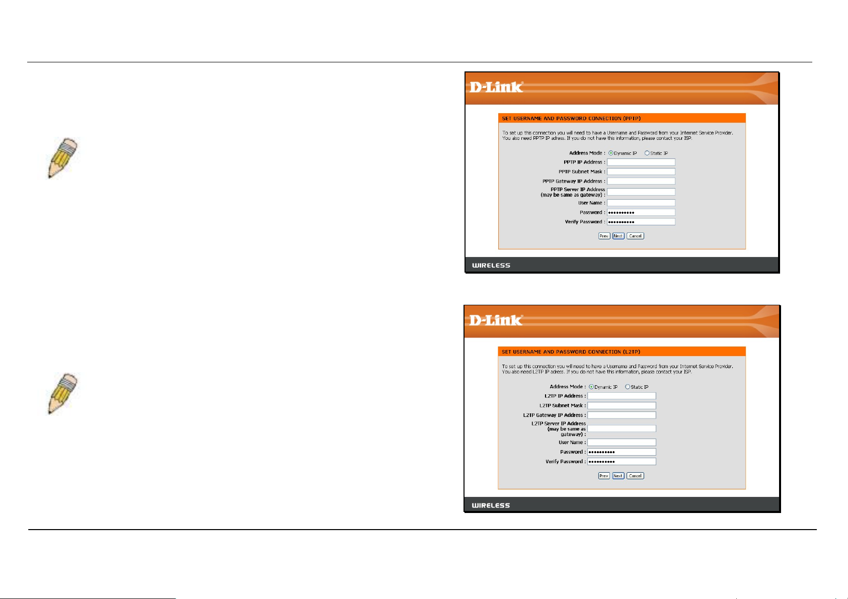
Username/Password (PPTP) - To configure the PPTP client connection,
enter the IP and account information for the router. Your ISP will give this
information to you if you are establishing a PPTP connection to the ISP.
Click Next to continue.
NOTE: The broadband device used for your Cable or ADSL network connection must support
PPTP pass-through so the VPN session can be established.
Username/Password (L2TP) - To configure the L2TP client connection,
enter the IP and account information for the router. Your ISP will give this
information to you if you are establishing a L2TP connection to the ISP.
Click Next to continue.
NOTE: The broadband device used for your Cable or ADSL network connection must support
L2TP pass-through so the VPN session can be established.
D-Link DIR-320 User Manual
13
Page 17
Section 3 – Configuration
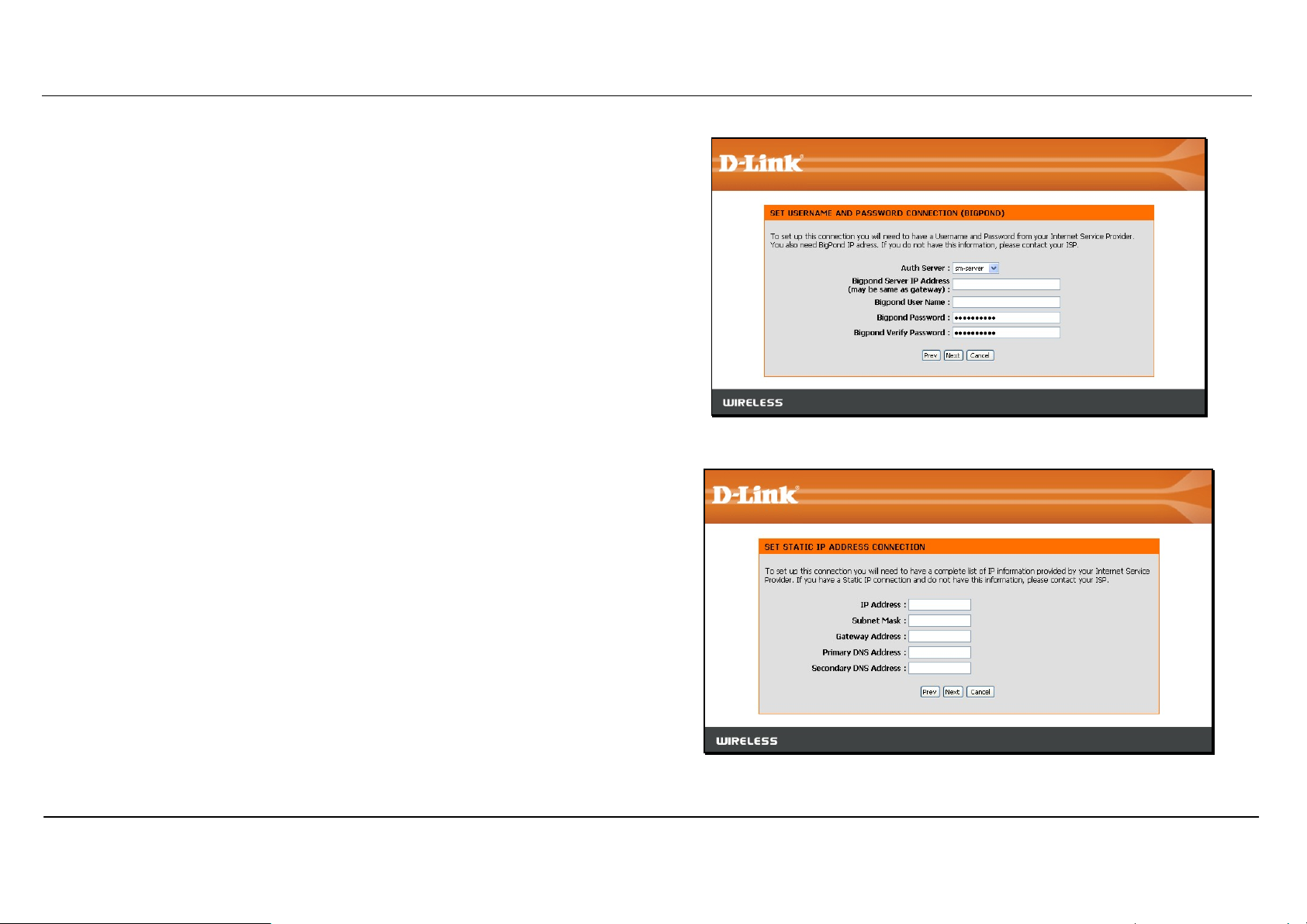
Username/Password (Bigpond) - BigPond Cable connections use this
Enter the account and server information, as provided to you by BigPond.
Click Next to continue.
Static IP Address Connection - For Static IP Address connection types,
you must type in the IP Address, Subnet Mask, Gateway Address,
Primary DNS Address and Secondary DNS Address (optional). Your
ISP should provide this information to you. Click Next to continue.
D-Link DIR-320 User Manual
14
Page 18
Section 3 – Configuration
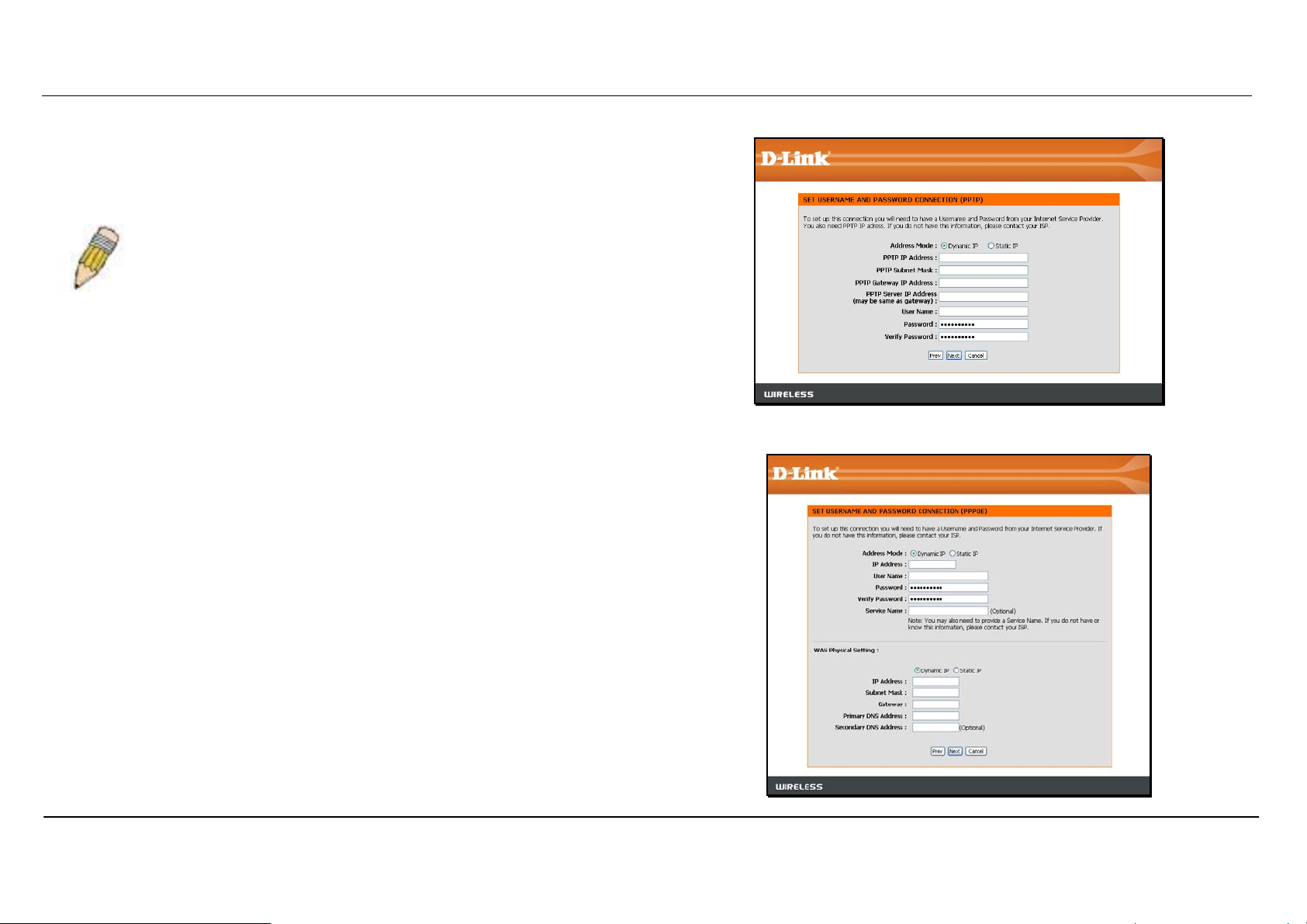
Russia PPTP (Dual Access) - To configure the PPTP client connection,
enter the IP and account information for the router. Your ISP will give this
information to you if you are establishing a PPTP connection to the ISP.
Click Next to continue.
NOTE: The broadband device used for your Cable or ADSL network connection must support
PPTP pass-through so the VPN session can be established.
Russia PPPoE (Dual Access) - For PPPoE connections, select the
Address Mode Dynamic IP or Static IP, type in the Username and
Password used to identify and verify your account to the ISP. Retype the
password again and if necessary, type a Service Name or domain name.
For Static IP address mode, type the IP Address assigned to your
account. Your ISP should provide this IP address along with other account
information. An additional set of IP settings might be required to create a
static route to the ISP. Enter the WAN IP settings used to create this route
(as given by the ISP) and click Next to continue.
D-Link DIR-320 User Manual
15
Page 19
Section 3 – Configuration
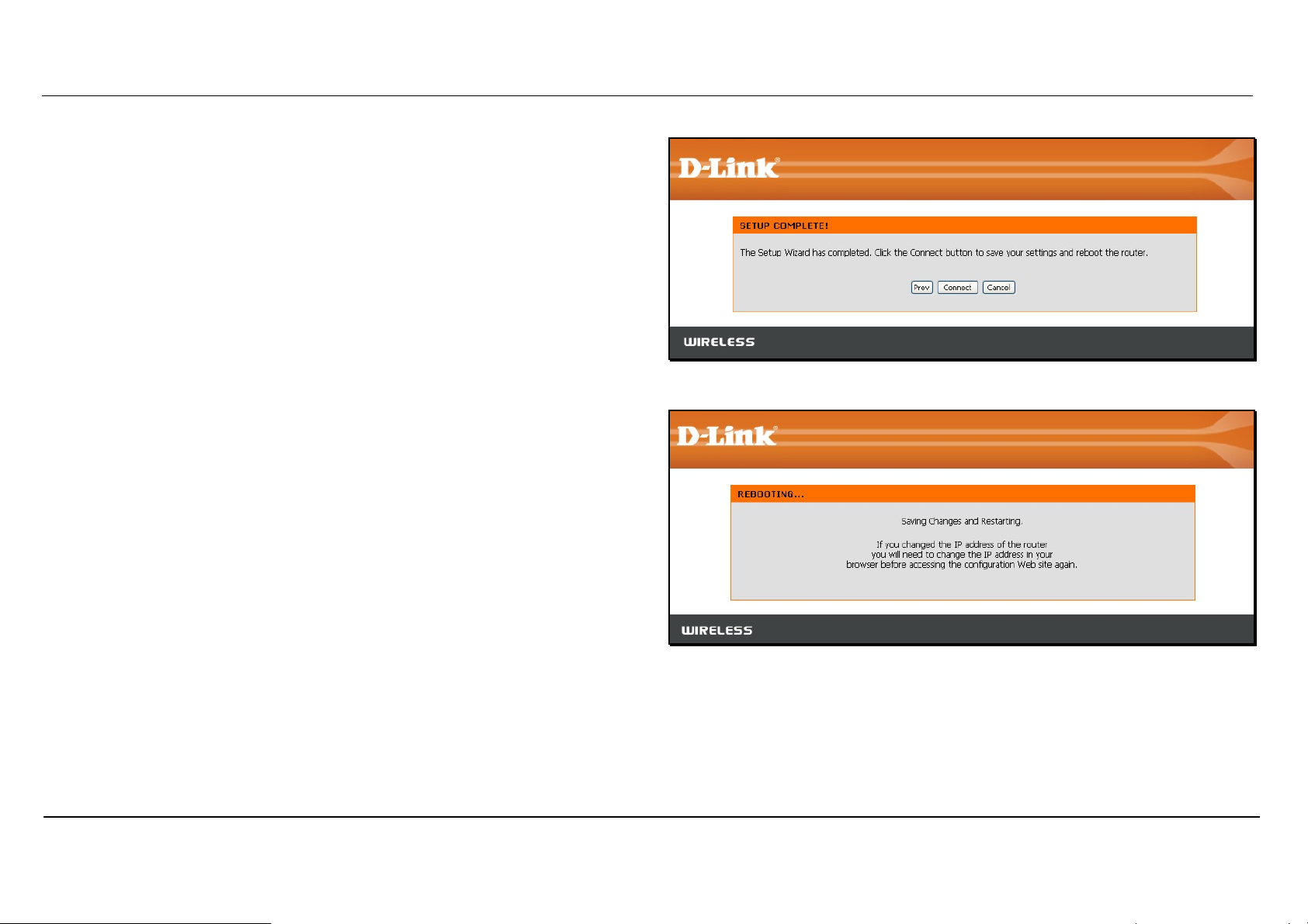
When you are satisfied that the settings have been entered correctly click
on the Connect button to save the new configuration settings.
During the save and restart procedure, the display informs that it is
rebooting. Once the reboot is complete, begin to use the router.
D-Link DIR-320 User Manual
16
Page 20
Section 3 – Configuration
Configure Internet Connection – Manual Setup
The Internet connection can be configured manually without
using the Setup Wizard. To configure Internet connection
settings manually click on the Manual Internet Connection
Setup button in the Internet Connection menu.
In the new menu select the Internet Connection type used for
your service from the My Internet Connection is: pull-down
menu. Follow the instructions in the next sections according to
the type of Internet connection you want to configure.
D-Link DIR-320 User Manual
17
Page 21
Section 3 – Configuration
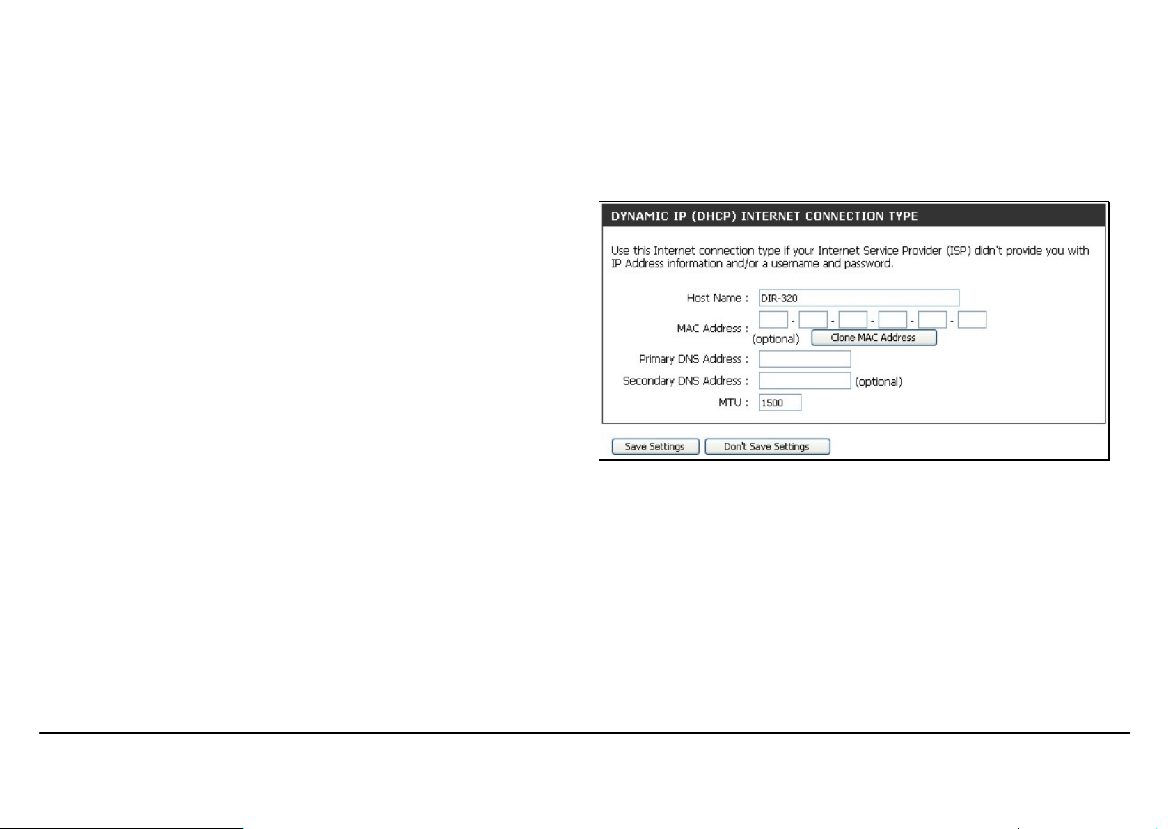
Dynamic IP Address
To configure a Dynamic IP Address Internet connection, follow these
steps:
1. Select the Dynamic IP (DHCP) option from the My Internet
Connection is: pull-down menu.
2. Under the Dynamic IP heading, type a Host Name if needed, and
DNS IP address information. The Primary DNS Address will be
normally be required, the Secondary DNS Address is used for a
back up DNS server.
3. Some ISPs record the unique MAC address of your computer’s
Ethernet adapter when you first access their network. This can
prevent the Router (which has a different MAC address) from being
allowed access to the ISPs network (and the Internet). To clone the
MAC address of your computer’s Ethernet adapter, type in the
MAC address in the MAC Address field and click the Clone MAC
Address button.
4. Leave the MTU value at the default setting (default = 1500) unless
you have specific reasons to change this (see table below for more
information).
5. Click on the Save Settings button to save and apply the new
Internet connection settings.
A Dynamic IP Address connection configures the Router to
automatically obtain its global IP address from a DHCP server on the
ISP’s network.
D-Link DIR-320 User Manual
18
Page 22
Section 3 – Configuration
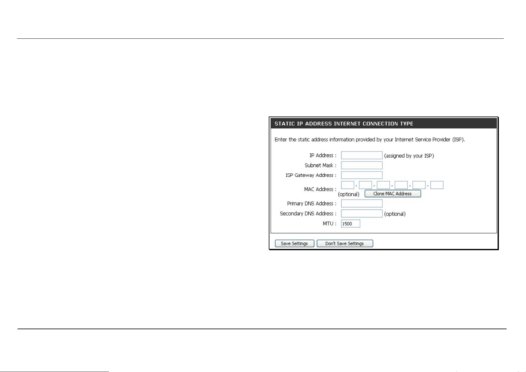
Static IP Address
To configure a Static IP type Internet connection, follow these steps:
1. Select the Static IP option from the My Internet Connection is:
pull-down menu.
2. Under the Static IP heading, type IP address information provided
by your ISP, type an IP Address, Subnet Mask and ISP Gateway
Address. The Primary DNS Address will be normally be required,
the Secondary DNS Address is used for a back up DNS server.
3. Some ISPs record the unique MAC address of your computer’s
Ethernet adapter when you first access their network. This can
prevent the Router (which has a different MAC address) from being
allowed access to the ISPs network (and the Internet). To clone the
MAC address of your computer’s Ethernet adapter, type in the
MAC address in the MAC Address field and click the Clone MAC
Address button.
4. Leave the MTU value at the default setting (default = 1500) unless
you have specific reasons to change this (see table below for more
information).
5. Click on the Save Settings button to save and apply the new
Internet connection settings.
When the Router is configured to use Static IP Address assignment
for the Internet connection, you must manually assign a global IP
Address, Subnet Mask, and ISP Default Gateway IP address. Most
users will also need to configure DNS server IP settings. Follow the
instruction below to configure the Router to use Static IP Address
assignment for the Internet connection.
D-Link DIR-320 User Manual
19
Page 23
Section 3 – Configuration
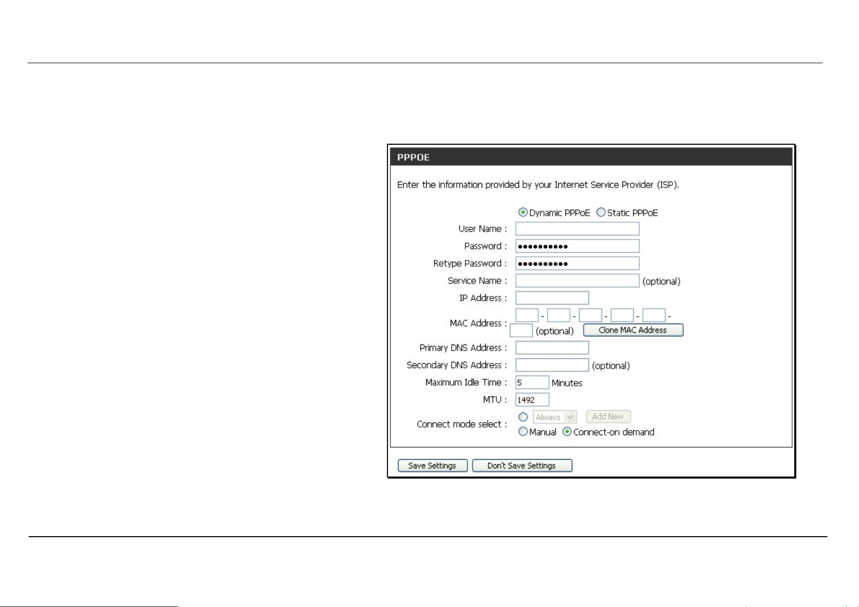
PPPoE
PPP or Point-to-Point protocol is a standard method of establishing a network connection/session between networked devices. Different forms of
PPP include PPPoA and PPPoE (discussed below) involve an authentication process that requires a username and password to gain access to the
network. PPPoE (PPP over Ethernet), as described in RFC 2516, is a method of using PPP through the Ethernet network.
To configure a PPPoE Internet connection, follow these steps:
1. Select the PPPoE (Username / Password) option from
the My Internet Connection is: pull-down menu.
2. Choose the IP address assignment option (Dynamic
PpoE or Static PPPoE). Static IP address assignement
requires manual entry of IP settings information.
3. Under the PPPoE heading, type the User Name and
Password used for your account. A typical User Name
will be in the form user1234@isp.co.ru. The Password may
be assigned to you by your ISP or you may have selected
it when you set up the account with your ISP. Type the
password again in Confirm Password.
4. For Static PPPoE connections, enter IP settings provided
by the ISP and, if necessary enter MAC address (see
table below)
5. Leave the MTU value at the default setting (default =
1492) unless you have specific reasons to change this
(see table below for more information).
6. Choose the desired Connection Setting. Select from:
Always ON, Connection On Demand, or Manual. Most
users will want to choose the default connection setting,
Always ON.
See table below for parameter description.
D-Link DIR-320 User Manual
20
Page 24
Section 3 – Configuration
Some of the settings do not need to be changed the first time the device is set up, but can be changed later if you choose. The information that is to
be provided in this window must be given to you by your ISP and must be carefully configured. Any small discrepancy will send the wrong message
to your ISP’s server and inhibit your connection.
There are two ways to configure the PPoE connection on the router, one is for a Dynamic PPPoE configuration, which means the router will
implement some settings automatically through DHCP, such as the router’s IP address and the default gateway. The other is through a Static
PPPoE connection, in which the user must configure the IP address and the DNS addresses automatically.
PPPoE Description
User Name
Password
Retype Password
Service Name
IP Address
MAC Address This field will instruct the user to enter the Media Access Control (MAC) address of the Ethernet Card of your computer, if instructed
Primary DNS Address This entry is for the IP address of your primary domain name server, which should also be provided to you by your ISP. The router
Secondary DNS
Address
Maximum Idle Time A value of 0 means that the PPP connection will remain connected. If your network account is billed according to the amount of time
MTU This field refers to the Maximum Transfer Unit, which is the maximum size of a packet, in bytes, that will be accepted by the router.
Connect Mode Select This function, with Connect-on-demand selected, will allow the router to connect any workstation on your LAN to the Internet upon
The user name supplied to you by your ISP.
The password supplied to you by your ISP.
Retype the password entered in the Password feld.
Enter the service name supplied to you by your ISP, if required.
Enter the IP address given to you by your ISP. This field is only to be completed if the Static PPPoE button is selected.
to do so by your ISP. To quickly accompli sh this, click the Clone MAC address button, which will automatically copy the MAC address
of your Ethernet card and enter it into the space provided, which will replace the MAC address of the router.
will first try the Primary DNS Address to resolve a website’s URL IP address. If this IP address fails, the router will then try the
Secondary DNS Address. This field is only to be completed if the Static PPPoE button is selected.
The IP address of the secondary domain name server will be used to resolve a website’s URL IP address if the Primary DNS Address
fails. The information in this field should also be provided by your ISP and is only to be completed if the Static PPPoE button is
selected.
the Router is actually connected to the Internet, enter an appropriate Idle Time value (in seconds). This will disconnect the Router
after the WAN connection has been idle for the amount of time specified. The default value = 5.
The default setting is 1492 bytes. This field should not be altered unless instructed by your ISP.
request. If this function is set at Always-on, no request from the workstation will be needed to connect to the Internet. If Manual
is selected, it will be necessary for the workstation on the LAN to manually connect to the Internet through this router.
D-Link DIR-320 User Manual
21
Page 25

Section 3 – Configuration
PPTP
The Point to Point Tunneling Protocol is used to transfer information
securely between VPNs (Virtual Private Routers). Encryption methods
are employed in the transfer of information between you and your ISP
using a key encryption. This option is specific for European users where
ISPs support the PPTP protocol for the uplink connection. To connect to
your ISP’s server using this protocol, the information in this window
must be provided to you by your ISP and then properly implemented.
There are two ways to enable the router to become a PPTP client, one
is through assigning the router an IP address dynamically, which means
that the DHCP protocol will be implemented by the Router to
automatically configure the IP settings. The user may input the IP
settings manually by choosing the Static IP option above the configuring
area. To configure the router to be a PPTP client, complete the entry
fields and click the Save Settings button.
See table below for parameter description.
D-Link DIR-320 User Manual
22
Page 26

Section 3 – Configuration
PPTP/L2TP Description
IP Address Enter the IP address of the router into this field. This address must be supplied to you by your ISP. This field will not be necessary
to configure if the Dynamic IP option is chosen above the configuring field.
Subnet Mask Enter the IP address of the Subnet Mask into this field. This address must be supplied to you by your ISP. This field will not be
necessary to configure if the Dynamic IP option is chosen above the configuring field.
Gateway Enter the IP address of the gateway into this field. This address must be supplied to you by your ISP. This field will not be
necessary to configure if the Dynamic IP option is chosen above the configuring field.
DNS Enter the IP address of the DNS. This field will not be necessary to configure if the Dynamic IP option is chosen above the
configuring field.
MAC Address This field will instruct the user to enter the Media Access Control ( MAC) address of the Ethernet Card of your computer, if
instructed to do so by your ISP. To quickly accomplish this, click the Clone MAC address button, which will automatically copy
the MAC address of your Ethernet card and enter it into the space provided, which will replace the MAC address of the router.
Server IP/Name Enter the Server IP address for this protocol into this field. This is the IP address of the server computer that will be used, along
with your computer, to create the Virtual Private Network. This field must be completed for both the Dynamic IP and Static IP
options
PPTP/L2TP Account
PPTP/L2TP Password
PPTP/L2TP Retype
Password
Maximum Idle Time A value of 0 in this field means that the PPTP/L2TP connection will remain connected. If your network account is billed according
MTU This field refers to the Maximum Transfer Unit, which is the maximum size of a packet, in bytes, that will be accepted by the
Connect Mode Select This function, with Connect-on-demand selected, will allow the router to connect any workstation on your LAN to the Internet
Enter the PPTP/L2TP account name, provided to you by your ISP, here.
Enter your password for this PPTP/L2TP account here, as stated to you by your ISP.
Retype the password entered in the PPTP/L2TP Password field.
to the amount of time the Router is actually connected to the Internet, enter an appropriate Idle Time value (in seconds). This
will disconnect the Router after the WAN connection has been idle for the amount of time specified. The default value = 5.
router. The default setting is 1460 bytes. This field should not be altered unless instructed by your ISP.
upon request. If this function is set at Always-on, no request from the workstation will be needed to connect to the Internet. If
Manual is selected, it will be necessary for the workstation on the LAN to manually connect to the Internet through this router.
D-Link DIR-320 User Manual
23
Page 27

Section 3 – Configuration
L2TP
L2PT, or Layer 2 Tunneling Protocol is a VPN protocol that will ensure a
direct connection to the server using an authentication process that
guarantees the data originated from the claimed sender and was not
damaged or altered in transit. Once connected to the VPN tunnel, it
seems to the user that the client computer is directly connected to the
internal network. To set up your L2PT connection, enter the data that was
provided to you by your ISP.
There are two ways to enable the router to become a L2TP client, one is
through assigning the router an IP address dynamically, which means that
the DHCP protocol will be implemented by the Router to automatically
configure the IP settings. The user may input the IP settings manually by
choosing the Static IP option above the configuring area. To configure the
router to be a L2TP client, complete the following fields and click the Save
Settings button.
See table on previous page for parameter description.
D-Link DIR-320 User Manual
24
Page 28

Section 3 – Configuration
BigPond
BigPond Cable connections use this menu to configure account and
connection information. Enter the account information, as provided to
you by BigPond. Click Next to continue.
BigPond
Description
Connection Setting
Auth Server Enter the name of the Authentication Server
as provided to you by BigPond.
User Name The account name of the account that has
been assigned to you by BigPond.
Password The password of the account that was
supplied to you by BigPond.
Confirm Password Retype the password that was entered in the
BigPond Password field. Ensure that these
two passwords are identical or an error will
occur.
Login Server
IP/Name
MAC Address This field will instruct the user to enter the
Enter the Server IP address for this protocol
into this field. This is the IP address of the
server computer that will be used, along with
your computer, to create the Virtual Private
Network. This field must be completed for
both the Dynamic IP and Static IP options
Media Access Control (MAC) address of the
Ethernet Card of your computer, if instructed
to do so by your ISP. To quickly accomplish
this, click the Clone MAC address button,
which will automatically copy the MAC
address of your Ethernet card and enter it
into the space provided, which will replace
the MAC address of the router.
D-Link DIR-320 User Manual
25
Page 29

Section 3 – Configuration
PPTP Russia
The PPTP Russia setup is identical to the previously described PPTP
setup on page 22 except an option to use a MAC address that will always
be associated with the connection. The MAC address is entered manually
or copied form the computer.
To configure a PPTP Russia Internet connection, configure as previously
described for PPTP connections and type in the MAC address that will be
used or clone the computer’s MAC address by clicking on the Clone MAC
Address button.
D-Link DIR-320 User Manual
26
Page 30

Section 3 – Configuration
PPPoE Russia
Some PPPoE connections use a static IP route to the ISP in addition to
the global IP settings for the connection. This requires an added step to
define IP settings for the physical WAN port.
To configure a PPPoE Russia Internet connection, configure as previously
described for PPPoE connections on page 20 and add the WAN Physical
IP settings as instructed from the ISP.
D-Link DIR-320 User Manual
27
Page 31

Section 3 – Configuration
Configure Wireless Connection - Setup Wizard
Configure the router’s wireless access point with the Wireless
Connection Setup Wizard and follow the instructions that
follow. Or use the manual configuration option. To configure
basic wireless and wireless security settings manually click on
the Manual Wireless Connection Setup button.
D-Link DIR-320 User Manual
28
Page 32

Section 3 – Configuration
Wireless Connection Setup Wizard
Use the Wireless Connection Setup Wizard to quickly configure the Internet connection. Click on the Wireless Connection Setup Wizard button in
the Wireless Connection menu to begin using the wizard.
The first wizard menu provides a summary of the setup procedure. The
procedure is the same for all security types used. If you want to make
specific changes to wireless security settings, use the manual wireless
connection setup option. The steps for wireless connection setup are:
1. Name your wireless network
2. Secure your wireless network
3. Set your wireless security password
Click the Next button to proceed.
Type the SSID or name of your wireless network and click Next to
proceed. Any wireless client or device that associates with the router must
have this SSID.
D-Link DIR-320 User Manual
29
Page 33

Section 3 – Configuration
Select the level of security for the wireless network. The choice will
determine the method used for security. The security options are:
• Best – using WPA2
• Better – using WPA
• Good – using WEP
• None – no security for the wireless connection
Remember that all wireless clients that will associate with the router must
use the same security settings.
Click Next to continue to proceed.
Type the password used for security. The password will be converted into
the appropriate form used with the security option chosen before.
Click Next to continue to proceed.
D-Link DIR-320 User Manual
30
Page 34

Section 3 – Configuration
Wireless setup is completed. Review the wireless settings SSID and
security information. It is a good idea to keep a record of the wireless
settings in order to configure clients that will associate with the router.
Click Next to continue to save the new wireless settings and restart the
router.
Restarting will take several seconds. Once the router has restarted the
wireless settings just configured will be applied.
D-Link DIR-320 User Manual
31
Page 35

Section 3 – Configuration
Wireless Connection – Manual Setup
The wireless connection can be configured manually without using
the Setup Wizard. To configure wireless connection settings
manually click on the Manual Wireless Connection Setup button
in the Wireless Connection menu.
The two essential settings for wireless LAN operation are the
Wireless Network Name or SSID and Wireless Channel number.
The SSID (Service Set Identifier) is used to identify a group of
wireless LAN components. The SSID can be broadcast in order to
allow properly configured wireless stations to learn the SSID and
join the group.
D-Link DIR-320 User Manual
32
Page 36

Section 3 – Configuration
Wireless Network Settings
Use the Enable Wireless check box to disable or enable the wireless
interface. Wireless function is enabled by default.
The Wireless Network Name or SSID can be changed to suit your
wireless network. Remember that any wireless device using the access
point must have the same SSID and use the same channel. The SSID can
be a continuous character string (i.e. no spaces) of up to 16 characters in
length.
Wireless stations that support WPS can be configured automatically using
the Wi-Fi Protected Setup menu.
To manually configure security settings, select the Wireless Security
Mode form the pull-down menu and configure the settings for the security
method used. Follow the instructions below for the type of security used.
Click the Save Settings button to save any changes to the wireless
network settings.
D-Link DIR-320 User Manual
33
Page 37

Section 3 – Configuration
Wi-Fi Protected Setup
Wi-Fi Protected Setup or WPS makes wireless security configuration
much quicker simpler for wireless stations that support this feature.
NOTE: The Generate New PIN button is for the Router’s own PIN. This is used when the
Router needs to connect to other WPS enabled access points.
To connect a new wireless station with WPS, click on the Add Wireless
Device with WPS button. A new menu appears.
There are two methods available to connect a WPS wireless station, a
manual PIN entry or automatic method.
To use the PIN entry method, type the new station’s PIN number in the
space provided and click on the Connect button. The router begins
searching the wireless network for the device. Now begin the WPS
connection procedure with the device attempting connection. The router
will search for 120 seconds. If it fails to find the device, a message
appears explaining that the WPS connection failed.
To use the automatic WPS method, click on the Virtual Push Button. The
router begins searching the wireless network for the device. Now begin
the WPS connection procedure with the device attempting connection.
The router will search for 120 seconds. If it fails to find the device, a
message appears explaining that the WPS connection failed.
D-Link DIR-320 User Manual
34
Page 38

Section 3 – Configuration
Wireless Security - WEP
WEP security requires the following parameters be defined:
• Authentication: Select Open Key or Shared Key.
• Encryption: Select the encryption level, 64-bit or 128-bit.
• Default WEP Key: Up to four keys can be configured. Choose the
key being configured.
• WEP Key: Type an ASCII or Hex key of appropriate length for the
encryption level, 10 characters for 64-bit Hex or 26 characters for
128-bit Hex.
Click the Save Settings button to save any changes to the wireless
network security settings.
NOTE: If encryption of any kind, at any level is applied to the router, all wireless devices using
the router on the network must comply with all security measures.
D-Link DIR-320 User Manual
35
Page 39

Section 3 – Configuration
Wireless Security – WPA/EAP
Wi-Fi Protected Access was designed to provide improved data encryption, perceived as weak in WEP, and to provide user authentication, largely
nonexistent in WEP.
Enter the appropriate parameters for the type of security selected from
this menu. WPA EAP or WPA2 EAP must enter the following:
• Cypher Type: Choose TKIP, AES or Both.
• PSK/EAP: Choose EAP.
• RADIUS Server IP Address: The IP address of the RADIUS
server.
• Port: The port number used for 802.1x.
• Shared Secret: The password or character string used for wireless
station authentication.
D-Link DIR-320 User Manual
36
Page 40

Section 3 – Configuration
Wireless Security – WPA/PSK
Enter the appropriate parameters for the type of security from this menu.
WPA-PSK or WPA2-PSK must enter the following:
• Cypher Type: Choose TKIP, AES or Both.
• PSK/EAP: Choose PSK.
• Network Key: The password or character string used for wireless
station authentication (10 characters for 64-bit Hex).
D-Link DIR-320 User Manual
37
Page 41

Section 3 – Configuration
LAN Setup
Use the Network Settings menu to configure Router LAN IP Settings and DHCP
Server Settings. When you are finished, click the Save Settings button at the top of
the window.
D-Link DIR-320 User Manual
38
Page 42

Section 3 – Configuration
Router IP Settings
Router Settings
This section is used to configure the internal network settings of the
Router. This IP address is private to your internal network and cannot be
seen on the Internet. The default Router IP Address is 192.168.0.1 and
the Default Subnet Mask is 255.255.255.0. The Local Domain Name is
for the local Domain set on your network, if you have given it a name
previously. This field is for your personal use and unnecessary for proper
configuration of this window.
In addition, the Router can be configured to relay DNS from your ISP or
another available service to workstations on your LAN. When Enable
DNS Relay is checked, the Router will accept DNS requests from hosts
on the LAN and forward them to the ISP (or alternative) DNS servers.
Alternatively, you may also disable the DNS relay and configure hosts on
your LAN to use DNS servers directly. Most clients using the Router for
DHCP service on the LAN and are using DNS servers on the ISP’s
network, will leave DNS relay enabled.
D-Link DIR-320 User Manual
39
Page 43

Section 3 – Configuration
LAN DHCP Server Settings
DHCP Server Settings
Dynamic Host Configuration Protocol (DHCP) allows the gateway to automatically
obtain the IP address from a DHCP server on the service provider’s network. The
service provider assigns a global IP address from a pool of addresses available to the
service provider. T ypically the IP address assigned has a long lease time, so it will likely
be the same address each time the Router requests an IP address. If DHCP is not
enabled on the Router, it is necessary for the user to assign a static IP address to each
computer on your LAN.
To set up DHCP for your LAN, first enable the Router as a DHCP server by clicking the
Enable DHCP Server radio button in the window above. The next step is to set a range
of IP addresses that you wish to allot to the devices on your LAN by entering a starting
and ending number of addresses within the LAN subnet in the DHCP IP Address
Range. This may be in a range from 2 to 254 (192.168.0.2 – 192.168.0.254).
Computers on your LAN will have an IP address within this range then automatically
assigned to them. Finally, choose the DHCP Lease Time, which is the time the Server
will set for devices using DHCP to re-request an IP Address. Clients authorized for
DHCP will be listed in the Dynamic DHCP Client List near the bottom of the window.
Click Save Settings to implement information set in this table. The DHCP Server is
enabled by default. DHCP may also be statically configured as well. This method allows
the router to assign the same IP address information to a specific computer on the
network, defined by its MAC address. This computer will get the same DHCP
implemented IP address information every time the computer is turned on and this IP
address will be specific to that computer’s IP address on the local network. No other
computer can be assigned this address. This is useful for computers on the LAN that
are hosting applications such as HTTP or FTP. First, the user must enter the Host
Name and the IP Address for that computer in the spaces provided. Next, the user
must enter the MAC Address of the computer in the space provided. Click Save
Settings to implement these static settings.
D-Link DIR-320 User Manual
40
Page 44

Section 3 – Configuration
Printer Setup
Printer Setup Wizard
Use the Printer Setup Wizard to configure the Router’s USB Printer
connection. To establish the connection to a USB equipped printer, click
the Printer Setup link to view the Printer Setup Wizard launch menu.
Follow the instructions below to install the printer driver on your
computer. Some printers, especially very recent release printers, might
require the Printer CD-ROM containing the printer driver that came with
the printer. This procedure must be followed by any computer that will
use the printer.
To use a printer connected to the USB printer port on the DIR-320:
1. Have the CD-ROM with the printer driver available, it might be
needed for the installation.
2. Power on the printer; follow the instructions included with the
printer to plug in the power cable and turn the power on.
3. Complete the USB connection from the DIR-320 USB to the USB
port on the printer. Check the LED indicator on the DIR-320 front
panel for the USB connection to make sure a physical connection
is established.
4. From the Printer Setup menu, click the Setup Wizard button to
launch the Printer Setup Wizard.
D-Link DIR-320 User Manual
41
Page 45

Section 3 – Configuration
The first Printer Setup Wizard menu lists the steps used for intallation.
Click the Next button to detect the printer.
The printer should be detected immediately. The model name will be
displayed if detected. If no printer is detected a warning tells you the
printer installation cannot be completed. Check the cable connections
and make sure the printer is powered on. Click Next if a printer is
detected.
It is now necessary to install the correct printer driver on your computer.
Click the Next button to launch the file.
D-Link DIR-320 User Manual
42
Page 46

Section 3 – Configuration
A setup will launch or attempt to launch on your computer. Often the
browser settings prevent the file from launching until permission is
granted. This file must be executed to install the printer driver. In
Windows Internet Explorer permission can be granted to launch
downloded application. See the example from Windows Internet
Explorer as seen in XP below. If asked to insert the CD-ROM containing
the printer driver, insert the CD-ROM in the CD-ROM drive of your
computer and install the printer driver according to the instructions for
the printer.
D-Link DIR-320 User Manual
43
Page 47

Section 3 – Configuration
Time and Date
The system time is the time used by the DIR-320 for scheduling
services. You can configure, update, and maintain the time on the
internal system clock.
To configure system time on the Router, select the method used to
maintain time. The options available include the default
Automatically synchronize with D-Link’s Internet timeserver
using Simple Network Time Protocol (SNTP), to use your
computer’s system clock, deselect the Automatic option and click the
Sync. your computer’s time settings button. Time can be sett
manually using the manual pull-down menus at the bottom of the
menu.
Click on the Save Settings button to save and apply the new time
configuration.
D-Link DIR-320 User Manual
44
Page 48

Section 3 – Configuration
Parental Control
Use this menu to deny access to specified websites and to set
Internet access time periods.
URL or Uniform Resource Locator is a specially formatted text
string that uniquely defines an Internet website. This menu will
allow users to block computers on the LAN from accessing
certain URLs.
To configure this menu for URL blocking, enter the website’s
address into the Website URL field, select the desired Schedule
and click the Add New button for that entry. Schedules can be
created using the Schedules menu in the Maintenance directory.
Click on the Save Settings button to save and apply the new web
access control configuration.
D-Link DIR-320 User Manual
45
Page 49

Section 3 – Configuration
Advanced Setup
The Advanced directory tab offers several configuration menus
including Port Forwarding, Application Rules, Access Control,
Firewall & DMZ, Advanced Wireless, Advanced Network,
Routing, QoS Engine, Guest Zone, and Traffic Manager. Click the
corresponding link in the left panel of the window. Port Forwarding is
the first menu listed and the first to appear when accessing the
Advanced directory.
D-Link DIR-320 User Manual
46
Page 50

Section 3 – Configuration
Port Forwarding
The Advanced Port Forwarding menu allows configuration for remote
users access to various services outside of their LAN through a
public IP address, such as FTP (File Transfer Protocol) or HTTPS
(Secure Web). After configuring the Router for these features, the
Router will redirect these external services to an appropriate server
on the users LAN. The Router has 13 pre-configured external
services already set, or manually set the port or port range used for
the rules.
To enable an already existing Port Forwarding Rule, click on its
corresponding checkbox and configure the appropriate fields listed
below. To configure other Port Forwarding Rules for the Router, use
the pull-down menus to select the computer or specify an IP
address, type the port or port range or select an application form the
pull-down menu, select the traffic type and click the Save Settings
button at the top of the window.
D-Link DIR-320 User Manual
47
Page 51

Section 3 – Configuration
Application Rules
Use the Application Rules menu to configure applications that
require multiple connections, such as Internet Telephony, video
conferencing, and Internet gaming. The following window lists six
Special Applications that commonly use more than one connection.
To configure one of these applications, tick its corresponding
checkbox and then modify the fields listed below the following figure.
The user may add a new application by modifying the fields listed
and then clicking the Save Settings button at the top of the window.
To enable an already existing Application Rule, click on its
corresponding checkbox. To configure other Application Rules for the
Router, type the port or port range or select an application form the
pull-down menu, type a name for the rule and select the traffic type
and click the Save Settings button at the top of the window.
D-Link DIR-320 User Manual
48
Page 52

Section 3 – Configuration
Access Control
Access Control, or MAC filtering, is a basic security measure that
should be used on any network that is exposed to a security risk. A
packet filter system examines data packets and scrutinizes them in
order to control network access. Filtering rules determine whether
packets are passed through the Router from either side of the
gateway. The rules are created and controlled by the network
administrator and can be precisely defined. These rules are used to
block access to the LAN from outside the network and/or to deny
access to the WAN from within the network.
MAC Filters
All computers are uniquely identified by their MAC (Media Access
Control) address. The following window will allow users to deny
computers access to the Internet or only allow certain computers
access to the Internet, based on their MAC address. To access this
window, click the Advanced tab along the top of the configuration
window, then the Access Control tab to the left hand side.
To configure MAC filters, manually enter a MAC address to be
filtered by ticking its corresponding checkbox and then configuring
the desired fields on the window above. Select Turn MAC Filtering
OFF, Turn MAC Filtering ON and ALLOW computers listed to access
the network, and Turn MAC Filtering ON and DENY computers listed
to access the network from the drop-down menu. When you are
finished, click the Save Settings button at the top of the window.
D-Link DIR-320 User Manual
49
Page 53

Section 3 – Configuration
Firewall & DMZ
The Firewall & DMZ menu is used to define enforce specific predefined policies intended to
protect against certain common types of attacks.
A DoS "denial-of-service" attack is characterized by an explicit attempt by attackers to
prevent legitimate users of a service from using that service. Examples include: attempts to
"flood" a network, thereby preventing legitimate network traffic, attempts to disrupt
connections between two machines, thereby preventing access to a service, attempts to
prevent a particular individual from accessing a service, or, attempts to disrupt service to a
specific system or person. To enable this function, tick the Enable DoS Prevention
checkbox.
Firewall Rules
To configure rules for the firewall, modify the following fields and click the Save Settings
button at the top of the window to set the rule in the Routers memory. Newly configured
firewall rules will be displayed in the Firewall Rules List at the bottom of the window.
Internal Attack Prevention
This is used for ARP attacks. The router will drop ARP inquiry packets when it detects an
extraordinarily high volume of ARP requests.
DMZ Host
Firewalls may conflict with certain interactive applications such as video conferencing or
playing Internet video games. For these applications, a firewall bypass can be set up using
a DMZ IP address. The DMZ IP address is a “visible” address and does not benefit from the
full protection of the firewall function. Therefore it is advisable that other security
precautions be enabled to protect the other computers and devices on the LAN. It may be
wise to use isolate the device with the DMZ IP address from the rest of the LAN.
For example, if you want to use video conferencing and still use a firewall, you can place
the server in the DMZ. The IP address of this server will then be the DMZ IP address. You
can designate the server’s IP address as the DMZ by typing in the IP address in the DMZ
IP Address space provided and then enabling its status by ticking the Enable DMZ Host
checkbox. Click the Save Settings button at the top of the window when you are finished.
D-Link DIR-320 User Manual
50
Page 54

Section 3 – Configuration
The Advanced Wireless menu is used
to configure settings that can increase
the performance of your router. Click
Save Settings when you have
completed your changes.
See the table below for descriptions of
the advanced wireless settings
parameters.
Advanced Wireless
D-Link DIR-320 User Manual
51
Page 55

Section 3 – Configuration
Performance
Description
Parameter
Transmit power Allows the user to adjust the transmit power of the router. A high transmit power allows a greater area range of accessibility to the router. When
multiple overlapping access points are present, it may be desirable to reduce transmission power.
Beacon Interval Beacons are emitted from the router in order to synchronize the wireless network. You may set the Beacon Interval range between 20-100
microseconds per beacon sent. The default is 100.
RTS Threshold The RTS (Request to Send) Threshold controls the size of data packets issued to a RTS packet. A lower level will send packets more frequently
which may consume a great amount of the available bandwidth. A high threshold will allow the router to recover from interf erence or collisions
which is more prevalent in a network with high traffic or high electromagnetic interference. The default setting is 2346.
Fragmentation The fragmentation threshold will determine if packets are to be fragmented. Packets over the 2346 byte limit will be fragmented before
transmission. 2346 is the default setting.
DTIM Period DTIM (Delivery Traffic Indication Message) Period is a countdown informing clients of the next menu for listening to broadcast and multicast
messages. The default setting is 1.
Preamble Type Long Preamble should be used where 802.11b clients are present.
CTS Mode Clear to Send mode should only be used when wireless clients are close enough to each other to “hear“ or detect the presen ce of ther other clients.
The Auto option will use CTS mode only when associating clients are in close proximity to each other.
802.11g Only Mode The router can be forced to associate with exclusively 802.11g devices.
Fragmentation The fragmentation threshold will determine if packets are to be fragmented. Packets over the 2346 byte limit will be fragmented before
transmission. 2346 is the default setting.
D-Link DIR-320 User Manual
52
Page 56

Section 3 – Configuration
Advanced Network
The Advanced Network Settings menu is used to disable or enable UPnP, disable Ping responses on the WAN port and change WAN port speed.
UPnP
UPnP supports zero-configuration networking and automatic discovery for many types
of networked devices. When enabled, it allows other devices that support UPnP to
dynamically join a network, obtain an IP address, convey its capabilities, and learn
about the presence and capabilities of other devices. DHCP and DNS service can also
be used if available on the network. UPnP also allows supported devices to leave a
network automatically without adverse effects to the device or other devices on the
network.
Diverse networking media including Ethernet, 802.11b/g Wireless, Firmware, phone line
and power line networking can support UPnP. To enable UPnP, tick the Enable UPnP
checkbox.
WAN Ping
This feature allow users to either allow or block a Ping test from outside computers
looking to check the connectivity of your device. This is usually attempted by hackers
trying to access your router or computer from a remote device on the WAN side of the
connection. Tick the Enable WAN Ping Respond checkbox to allow WAN pinging of
your device.
WAN Port Speed
This section allows the user to set the wire speed over which the router will transmit
packets. The user has three options:
10Mbps – Selecting this option from the drop-down menu will set the wire speed
at 10 megabytes per second.
100Mbps – Selecting this option from the drop-down menu will set the wire
speed at 100 megabytes per second.
10/100 Mbps Auto – Selecting this option from the drop-down menu will allow
the wire speed to be automatically set by the Router depending on the wire
speed available at any given time.
D-Link DIR-320 User Manual
53
Page 57

Section 3 – Configuration
Gaming Mode
When gaming mode is enabled, the router’s QoS settings are adjusted automatically to accommodate Internet gaming. Gaming mode is enabled by
default.
Multicast Streams
These options are used to enable and optimize multicast streaming. Open multicast ports receive enhanced priority during streaming. The wireless
enhance mode enables multicast streaming optimization for the wireless LAN.
Routing
Use Static Routing to specify a route used for data traffic within your
Ethernet LAN or to route data on the WAN. This is used to specify that
all packets destined for a particular network or subnet use a
predetermined gateway. Static routing on the WAN is only supported if
your WAN connection protocol is not using PPPoE.
To add a static route to a specific destination IP address, choose the
Interface, enter a Destination IP address, select a suitable Subnet
Mask, and type in the Gateway IP address. Click the Save Settings
button at the top of the menu when you are finished.
D-Link DIR-320 User Manual
54
Page 58

Section 3 – Configuration
QoS Engine
With some routers, all wired and wireless traffic, including VoIP, Video
Streaming, Online Gaming, and Web browsing are mixed together into a
single data stream. By handling data this way, applications like video
streaming could pause or delay. With D-Link Intelligent QoS Technology,
both wired and wireless traffic are analyzed and separated into multiple
data streams. These streams are then categorized by sensitivity to
delay, so applications like VoIP, Video Streaming, and Online Gaming
are given higher priority automatically . This enables multiple applications
to stream smoothly to your TV or PC.
Click the Save Settings button to implement the new QoS changes.
D-Link DIR-320 User Manual
55
Page 59

Section 3 – Configuration
The Guest Zone feature of the router allows an
additional subnet to be added. This is especially useful
for placing wireless stations in an IP subnet separate
from wired Ethernet stations. The four Ethernet ports
can also be configured to use the Guest Zone so one
or more Ethernet ports can be on a separate IP subnet.
To use a guest zone, click to select the Enable Guest
Zone box, if desired select a schedule when the Guest
Zone is effective. To create a new schedule, click the
Add New button to go to the Schedules menu.
The Guest Zone can be applied to any Ethernet port by
selecting it from the Include LAN Port menu.
To create a new wireless SSID for the Guest Zone,
check to select the Include Wireless box, then
configure the new Wireless Network Name (SSID) and
the security used for the new SSID.
The default IP subnet for the guest zone is
192.168.1.0. To change the IP address scheme for the
guest zone type the new Router IP Address and
Subnet Mask in space provided.
Guest Zone
If the Enable Guest Zone Client Isolation option is
selected, the router will not exchange traffic between
clients on the guest zone’s newly created subnet.
Guest zone clients will be able to access the Internet
only.
Click the Save Settings button to implement the
changes.
D-Link DIR-320 User Manual
Guest Zone menu (upper portion)
56
Page 60

Section 3 – Configuration
Routing between the guest zone and the original host
subnet can be enabled by clicking the Enable Routing
Between Zones box. If this option is not selected, the
two subnets will behave as separate networks with
access to the Internet connection, but not to computers
on the other subnet.
The DHCP server for the guest zone is configured
exactly the same as the DHCP server to the original
host zone. DHCP clients on the guest zone are listed
below the DHCP server setup menu.
The Enable Guest Zone Client option will create static
IP addresses for all current DHCP clients and leasers.
When this is enabled, no more DHCP clients are
allowed, the list is locked.
Click the Save Settings button to implement the
changes.
Guesst Zone menu (lower portion)
D-Link DIR-320 User Manual
57
Page 61

Section 3 – Configuration
Traffic Management
The Traffic Manager is used to control Internet connection bandwidth for
individual computers on the wired or wireless network. Up to 26 clients
can be added to the list for bandwidth control.
D-Link DIR-320 User Manual
58
Page 62

Section 3 – Configuration
Maintenance
The menus of the Maintenance directory include Device Administration, Save and Restore, Firmware Update, DDNS Setting, System Clock,
Schedules and Log Settings.
Device Administration
The Device Administrator menu is used to change the administrator’s
login name and password as well as remote management set up. To
change the login name or password, enter the new Login Name and
password into the New Password field and repeat the password in the
Confirm Password field. Click Save Settings to set your new
password.
This window will also allow the user to enable remote management of
the device from a remote computer. To configure this function, click
Enable Remote Management under the Remote Management
heading and type IP address of the system used for remote
management. Click Save Settings to set these configurations into the
memory of the Router.
D-Link DIR-320 User Manual
59
Page 63

Section 3 – Configuration
Save and Restore
Current system settings can be saved as a file onto the local hard drive
by clicking the Save button. The saved file or any other saved setting file
can be loaded back on the Router. To reload a system settings file, click
on Browse to browse the local hard drive and locate the system file to
be used. You may also reset the Router back to factory settings by
clicking on Restore Device.
D-Link DIR-320 User Manual
60
Page 64

Section 3 – Configuration
Firmware Update
View the version of the currently loaded firmware and update the system firmware with the Firmware Update menu. Make sure the firmware you
want to use is on the local hard drive of the computer. Click on Browse to browse the local hard driver and locate the firmware to be used for the
update. Please check the D-Link support site for firmware updates at D-Link Technical support website of your country.
In order to keep pace with changes in standards and technology, the
DIR-320 allows you to easily update the embedded firmware. You may
obtain the latest version of the DIR-320 firmware by logging onto the
D-Link web site at www.dlink.com. If you are connected to the Internet,
you can access the D-Link web site by clicking on Check Now. The
Firmware Upgrade window lists the version of the firmware the Router is
currently using. If you would like to update, follow the instructions given
on the D-Link web site firmware update page to download the new
firmware. You can then use the DIR-320 Firmware Upgrade Utility
included with the Router to transfer the new firmware to the Router . Once
you have downloaded the new firmware to your computer, use the
Browse button to find where it is located on your computer, or if you
know the path of the file, enter it into the space provided. Click Apply to
begin the download. After the new firmware has been successfully
downloaded into your Router, restart the device to let the changes take
effect.
D-Link DIR-320 User Manual
61
Page 65

Section 3 – Configuration
DDNS Setting
The DIR-320 supports DDNS or Dynamic Domain Name Service.
Dynamic DNS allows a dynamic public IP address to be associated with
a static host name in any of the many domains, allowing access to a
specific host from various locations on the Internet. With this function
enabled, remote access to a host will be allowed by clicking a URL
hyperlink in the following form: dlinkddns.com Because many ISPs
assign public IP addresses using DHCP, it can be difficult to locate a
specific host on the LAN using the standard DNS. For example, if you
are running a public web server or VPN server on your LAN, DDNS
ensures that the host can be located from the Internet if the public IP
address changes. DDNS requires that an account be set up with one of
the supported DDNS servers.
To implement Dynamic DNS, first tick the Enable DDNS checkbox in the
window above, then choose the Server Address from the list in the
pull-down menu. Next, enter the Host Name of the LAN to be accessed,
and the Username and Password for the DDNS account. Click the
Save Settings button to save changes made. Use the DDNS Account
Testing button to make sure the DDNS service is functioning.
D-Link DIR-320 User Manual
62
Page 66

Section 3 – Configuration
System Check
This menu is used to monitor port performance and connectivity, the menus
displayed are VCT Info and Ping Test.
VCT Info
The Virtual Cable Tester displays the current status of all ports.
Ping Test
The Ping Test section allows you to ping any IP address from the Router to
test connectivity to the address. To Ping a device, enter the IP address of the
device that you wish to ping into the Host Name or IP Address field and click
Ping to start the Ping mechanism. The results of the Ping will be shown under
the Ping Result heading.
D-Link DIR-320 User Manual
63
Page 67

Section 3 – Configuration
Schedules
This window is used to create implementation schedules. This is the
same menu accessed using the Make New Schedule button in the
rules menu of various settings pages.
Schedule rule setup menu
Complete the Add Schedule Rule settings on the window above and
then click the Save Settings button at the top of the window.
NOTE: Make sure the time in Router is synchronized with your local time
to have the schedule setting work properly.
If the router is reset or powered off, the schedule function will not work as
expected since the router time will be incorrect.
D-Link DIR-320 User Manual
64
Page 68

Section 3 – Configuration
Log Settings
The system log displays chronological event log data, including System
Activity , Debug Information, Attacks, Dropped Packets, and Notice. Check the
desired category of Log Type in the bottom half of the window above and then
click the Save button and follow the prompts to save the file.
Alerts can be sent to an email account. Use the Send By Mail settings to
configure Email account information. Click the Send Me Now button to email
alerts to a previously configured email account.
D-Link DIR-320 User Manual
65
Page 69

Section 3 – Configuration
Status
The Status directory menus are used to check information about the Router, including Device Information, Log, Statistics, and Active Session.
Device Information
The Device Information display is used to view information
regarding the settings of the Router, both on the LAN side and
WAN side of the connection. The firmware version is also
displayed here as well as in the firmware upgrade menu.
D-Link DIR-320 User Manual
66
Page 70

Section 3 – Configuration
The Log displays events occurring within the router by time
and date, and also view the source and destination of the
event. The user may use the First Page, Last Page,
Previous and Next buttons to scroll through the log events
listed in the window. To clear the log events, click Clear.
Click the Link to Log Settings button to change what events
are displayed in the log.
Log
D-Link DIR-320 User Manual
67
Page 71

Section 3 – Configuration
The Statistics displays shows transmitted and received
packets occurring on the Router. To refresh the window, click
Refresh. To restart the packet count, click Reset.
Statistics
D-Link DIR-320 User Manual
68
Page 72

Section 3 – Configuration
Source and Destination packets passing through the Router
are displayed listed by TCP/UDP type in the Active Session
display. To refresh the window, click the Refresh button.
Active Session
D-Link DIR-320 User Manual
69
Page 73

Section 3 – Configuration
Wireless Client List
The Connected Wireless Client List displays all wireless
clients currently connected and the mode of the connection.
D-Link DIR-320 User Manual
70
Page 74

Appendix – Technical Specifications
Technical Specifications
Standards
• IEEE 802.11g
• IEEE 802.11b
• IEEE 802.3
• IEEE 802.3u
Wireless Signal Rates*
• 54 Mbps • 48 Mbps
• 36 Mbps • 24 Mbps
• 18 Mbps • 12 Mbps
• 11 Mbps • 9 Mbps
• 6 Mbps • 5.5
• 2 Mbps • 1 Mbps
Security
• WPA - Wi-Fi Protected Access (TKIP, MIC, IV Expansion,
Shared Key Authentication)
• WPS
Modulation Technology
802.11g 802.11b
• BPSK • DQPSK
• QPSK • DBPSK
• 16QAM • DSSS
• 64QAM • CCK
• OFDM
Wireless Frequency Range
2400 ~ 2497 MHz ISM band
Wireless Operating Range
• Indoors - up to 328 ft. (100 meters)
• 64/128-bit WEP
* Maximum wireless signal rate derived from IEEE Standard 802.11g specifications. Actual data
throughput will vary. Network conditions and environmental factors, including volume of network traffic,
building materials and construction, and network overhead, lower actual data throughput rate.
Environmental factors will adversely affect wireless signal range.
• Outdoors- up to 1312 ft. (400 meters)
External Antenna Type
Single detachable reverse SMA
D-Link DIR-320 User Manual
71
Page 75

Appendix – Technical Specifications
VPN Pass Through/ Multi-Sessions
• PPTP
• IPSec
Device Management
• Web-based Internet Explorer v6 or later; Netscape
• Navigator v6 or later; or other Java-enabled browsers
• DHCP Server and Client
Advanced Firewall Features
• NAT with VPN Pass-through (Network Address Translation)
• MAC Filtering
• IP Filtering
• URL Filtering
• Domain Blocking
• Scheduling
Power
Input: DC 5V 2A
Operating Temperature
32°F to 104°F (0°C to 40°C)
D-Link DIR-320 User Manual
72
Page 76

Appendix – Technical Specifications
Humidity
Operating humidity 10% - 90% maximum (non-condensing)
Safety and Emissions
FCC
LEDs
• Power
• Status
• Internet
• WLAN (Wireless Connection)
• LAN (10/100)
• USB
Dimensions
L = 5.6 (142mm)
W = 4.3 (109mm)
H = 1.2 inches (31mm)
Weight
7.8 oz (0.22kg)
Warranty
1 Year
D-Link DIR-320 User Manual
73
Page 77

Appendix – Technical Specifications
SETUP ADVANCED MAINTENANCE STATUS HELP
Web-based management function navigator
Internet Setup Port Forwarding
Wireless Setup
LAN Setup Access Control Firmware Update Statistics
Printer Setup Firewall & DMZ DDNS Setting Active Session
Time and Date
Parental
Control
Logout Routing Log Settings
QoS Engine Logout
Guest Zone
Traffic
Application
Rules
Advanced
Wireless
Advanced
Network
management
Device
Administration
Save and Restore Logs Logout
System Check LAN Clients
Schedules Logout
Device Info Menu
Logout
D-Link DIR-320 User Manual
74
 Loading...