

Page 1
Page 2
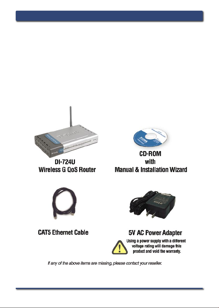
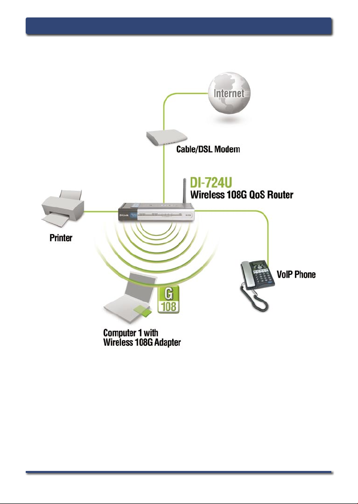
System Requirements
Ethernet
Computers with Win
operating sy
Internet
above
-based Cable or D
dows, Ma
stems
with an inst
Explorer
Version 6.0 or Net
SL Modem
cintosh, or Linux
alled Ethernet adap
Package Contents
DI-724U Install GuideSystem Requirements
scape Nav
-
based
ter
igator 7.0 and
2 D-Link Systems, Inc.
Page 3
DI-724U Install Guide Hardware Overview
Hardware Overview
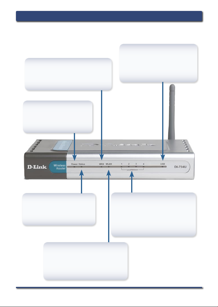
Front Panel
WAN LED
A solid light indicates a connection
on the WAN port. This LED blinks
during data transmission.
Power LED
A solid light indicates a
proper connection to the
proper power supply.
Status LED
A blinking light indicates that
the DI-724U is functioning
properly.
USB LED
A solid light ind i c a tes a
connection on the USB port.
This LED blinks during data
transmission.
Local Network LEDs
A soli d light on e a c h por t
indicates a connection to an
Ethernet enabled computer.
These LEDs blink during data
transmission.
WLAN LED
A solid light indicates that the
wireless segment is ready. This
LED blinks during wireless data
transmission.
D-Link Systems, Inc. 3
Page 4
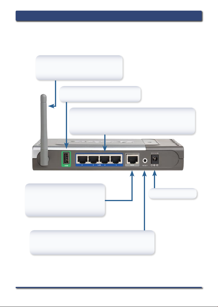
Back
Panel Connections
Antenna
Used to connect to 802.11g or
802.11b wireless adapters.
USB PORT
Connection for a USB printer.
DI-724U Install GuideHardware Overview
LAN PORTS
These are the connections for Ethernet cables
to Ethernet-enabled computers.
WAN PORT
This is for the connection of
an Ethernet cable to your
Cable or DSL modem.
Reset Button
Pressing this button restores the Router to its
original factory default settings.
Power Receptor
4 D-Link Systems, Inc.
Page 5

DI-724U Install Guide Connecting the DI-724U
Connecting The DI-724U Wireless G
QoS Router To Your Network
A. First, connect the power adapter to the receptor at the back panel
of the DI-724U and then plug the other end of the power adapter
to a wall outlet or power strip. The Power LED will turn ON to
indicate proper operation.
B. 1. Power off your Cable or DSL modem; som e devices
may not have a on/off switch and will require you to unplug
the power adapter. Now, the DI-724U should be powered
on and the Ca bl e /D SL modem sh o u ld be tur n ed off.
2. Cable/DSL modem (Power Off) – DI-724U (Power On)
Connect an Ethernet cable to the Ethernet jack located
on th e Ca ble/DSL modem. After the Ethernet cabl e is
securely co n n ec t e d, pow e r on the Ca ble / D S L modem
by turning on the unit or plugging in the power adapter.
3. Cable/DSL modem (Power On) – DI-724U (Power On) Insert
the other end of the Ethernet cable to the WAN PORT on the
back panel of the DI-724U. The WAN LED light will illuminate to
indicate proper connection. If the WAN LED is not illuminated,
please go back to step B1 and repeat the instructions.
C. Insert an Ethernet cable to LAN port 1 on the back panel of the
DI-724U and an available Ethernet port on the network adapter in
the computer you will use to configure the DI-724U. The LED light
for LAN Port 1 will illuminate to indicate proper connection. (Note:
The LAN Ports on the DI-724U are Auto-MDI/MDIX. Meaning
you can use a straight-through or crossover Ethernet cable to the
LAN Ports.)
D. Computers equipped with 802.11g wireless adapters will be able
to connect to the DI-724U. The DWL-G650 AirPlus Xtreme G
Wireless Cardbus Adapter and the DWL-G520 AirPlus Xtreme G
Wireless PCI Adapter will be able to connect out of the box with
the router using their default wireless settings.
D-Link Systems, Inc. 5
Page 6
Getting Started
DI-724U Install GuideConnecting the DI-724U
Please remember that D-Link Wireless 108G devices are pre-configured
to connect together, right out of the box, with their default settings.
6 D-Link Systems, Inc.
Page 7

DI-724U Install Guide Using The Setup Wizard
Using The Setup Wizard
Open your Web browser
and type “http://192.168.0.1”
into the URL address box.
Then press the Enter or
Return key.
The logon screen will
appear.
Select “admin” from the
username drop down menu
and leave the password
field blank.
Click Log In
Once you have logged
in, the Home screen will
appear.
Click Run Wizard
D-Link Systems, Inc. 7
Page 8

You will see the following
screens:
Click Next
Set up your new password.
You have the option to establish
a password for the username
“admin”.
Click Next
Choose your time zone
from the drop down list.
DI-724U Install GuideUsing The Setup Wizard
Click Next
8 D-Link Systems, Inc.
Page 9

DI-724U Install Guide Using The Setup Wizard
Select your Internet
Connection.
You w il l be pr o mpte d to
select the type of Internet
connection for your router.
If you are unsure of which
setting to select, pleas e
contact your Internet Service
Provider.
Click Next
If you selected Dynamic IP
Address, this screen will
appear: (Used mainly for
Cable Internet service.)
Click the “Clone MAC
Add r ess” but t on to
automatically copy the
MAC address of the
network adapter in your
computer. You can also
manually type in the
MAC address.
Click Next
This setup should be done on
the computer that is registered
on the ISP’s network.
D-Link Systems, Inc. 9
Page 10

If your ISP requires a Static
IP Address, and this option
is selected, then this screen
will appear:
Enter the IP address that
was originally provided to you
by your ISP. You will need
to complete all the required
fields.
Click Next
If your ISP uses PPPoE
(Point-to-Poi nt Prot ocol
over Ethernet), and this
option is selected, then this
screen will appear: (Used
mainly for DSL Internet
service.)
DI-724U Install GuideUsing The Setup Wizard
Enter in the username and
password provided to you
by your ISP.
Click Next
Please be sure to remove
any existing PPPoE client
software installed on your
computers.
10 D-Link Systems, Inc.
Page 11

DI-724U Install Guide Using The Setup Wizard
Wireless Setup
The default wireless settings
for your 802.11g wireless
network are:
SSID = default
Channel = 6
You c an ch a nge t hese
settings to match an existing
wireless network.
Click Next
If you wish to use encryption
for your 802.11g network, the
DI-724U is capable of two
types of wireless encryption
WEP and WPA. By default the
encryption is disabled. You
can change the encryption
settings for more secure
wireless communication.
Click Next
D-Link Systems, Inc. 11
Page 12

DI-724U Install GuideYour Setup is Complete
Your Setup is Complete!
Click Restart
Test Internet Connection
You will be returned to the Home tab. Close the web browser
window and relaunch your Web browser (i.e., Internet Explorer or
Netscape Navigator), to link to your favorite Web site to test your
Internet connection.
For additional settings or information, refer to the Advanced, Tools,
or Status tabs on the web-management interface; or to the Manual
located on the CD.
12 D-Link Systems, Inc.
Page 13

DI-724U Install Guide Configure Now Using WCN
Configure Wireless Settings Using WCN Wizard
The WCN wizard will copy
the wireless settings from
the computer being used
to access the router. This
computer needs to be
running Windows XP with
Service Pack 2 installed,
and needs to have already
gone through the Wireless
Network Setup Wizard.
Click Configure
Now Using WCN
Click OK
Click Install
ActiveX Control
D-Link Systems, Inc. 13
Page 14

DI-724U Install GuideConfigure Now Using WCN
Click Install
After installing Active X, click the “Configure Now Using WCN”
button again to launch this next screen.
Click Reboot
Click OK
14 D-Link Systems, Inc.
Page 15

DI-724U Install Guide Using The Printer Wizard
Using The Printer Wizard
Make sure your printer
is connected to the USB
port on the router.
Click Run Printer
Wizard
Click Next
The wizard will identify the
make and model of your
printer, as well as it’s status.
Click Next
D-Link Systems, Inc. 15
Page 16

Click Next to run the Printer
Setup application.
Click Next
Do not click Save. This
application can only run
when accessed from the
router.
Click Open
DI-724U Install GuideUsing The Printer Wizard
Click OK
16 D-Link Systems, Inc.
Page 17

DI-724U Install Guide Using The Printer Wizard
You may need to supply the
drivers for your printer if they
are not built into windows.
Click OK
Click OK
Select the location of the driver
files for your printer.
Once the wizard has completed
installing your printer, you will
be prompted to print a test page
to verify its functionality.
Click Yes
Click OK
Click Finish
D-Link Systems, Inc. 17
Page 18

To connect to the network, make sure
the network adapter in your computer
is configured properly. Here’s how to
configure the network adapter to obtain an
IP address automatically for the DI-724U
Wireless Broadband Router.
For Microsoft Windows XP:
Go to Start > right click on
My Network Places > select
Properties > Right click on
th e Ne twor k C o nn e cti on
associated with the Ether net
adapter and select Properties
(i.e., D-Link DFE-530TX+).
Click Internet Protocol
(TCP/IP)
Click Properties
DI-724U Install GuideAppendix
Select Obtain an IP
address automatically
Click OK
18 D-Link Systems, Inc.
Page 19

DI-724U Install Guide Appendix
For Apple Macintosh OS X:
Go to the Apple Menu Click on
System Preferences and Select
Network
Click on Network
Select Built-in Ethernet
in the Show pull down
menu
Select Using DHCP
in the Configure pull
down menu
The IP address information,
the Subnet Mask, the Router’s
IP address and the Ethernet
adapter address will appear.
Click on Apply Now
Restart your computer (if necessary)
D-Link Systems, Inc. 19
Page 20

Technical Support
D-Link’s website contains the latest user documentation and software up
dates for D-Link products.
D-Link provides free technical support for customers within the United States
and Canada for the duration of the product’s warranty period.
U.S. and Canadian customers can contact D-Link Technical Support through
our website or by phone.
United States
Telephone
(877) 453-5465
Twenty four hours a day, seven days a week.
World Wide Web
http://support.dlink.com
E-mail
support@dlink.com
Canada
Telephone
(800) 361-5265
Monday through Friday, 7:30am to 3:00am EST.
Saturday and Sunday, 9:00am to 12:00am EST
-
World Wide Web
http://support.dlink.ca
E-mail
support@dlink.ca
Version 1.0
Air
©2005 D-Link Corporation/D-Link Systems, Inc. All rights reserved. D-Link, the D-Link logo, and
Plus
Xtreme G
other countries. Other trademarks are the property of their respective owners. All references to speed are for
comparison purposes only. Product specifications, size, and shape are subject to change without notice, and
actual product appearance may differ from that depicted herein. Visit www.dlink.com for more details.
are registered trademarks of D-Link Corporation or its subsidiaries in the United States and
DI-724U 08032005
 Loading...