

D-Link DGS-3700, DGS-3700-12G, DGS-3700-12 Installation Manual

Hardware Installation Guide
Product Model:
Layer 2 Managed Gigabit Ethernet Switch
Release 2.00
DGS-3700 Series
©Copyright 2009. All rights reserved.

DGS-3700 Series Layer 2 Managed Gigabit Ethernet Switch Hardware Installation Guide
_________________________________________________________________________________
Information in this document is subject to change without notice.
© 2009 D-Link Corporation. All rights reserved.
Reproduction in any manner whatsoever without the written permission of D-Link Corporation is strictly forbidden.
Trademarks used in this text: D-Link and the D-LINK logo are trademarks of D-Link Corporation; Mic rosoft and Windows are registered tradem arks
of Microsoft Corporation.
Other trademarks and trade names may be used in this document to refer to either the entities claiming the marks and names or their products.
D-Link Corporation disclaims any proprietary interest in trademarks and trade names other than its own.
March 2011 P/N 651370012005G
ii

DGS-3700 Series Layer 2 Managed Gigabit Ethernet Switch Hardware Installation Guide
FCC Warning
This equipment has been tested and found to comply with the limits for a Class A digital device, pursuant to Part 15 of the FCC Rules. These limits
are designed to provide reasonable protection against harmful interference when the equipment is operated in a commercial environment. This
equipment generates, uses, and can radiate radio frequency energy and, if not installed and used in accordance with this manual, may cause
harmful interferenc e t o ra dio comm unications. Operation of this equipment in a residential area is likely to cause harmful interference in which case
the user will be required to correct the interference at their expense.
CE Mark Warning
This is a Class A product. In a domestic environment, this product may cause radio interference in which case the user may be required to take
adequate measures.
Warnung!
Dies ist ein Produkt der Klasse A. Im Wohnbereich kann dieses Produkt Funkstoerungen verursachen. In diesem Fall kann vom Benutzer verlangt
werden, angemessene Massnahmen zu ergreifen.
Precaución!
Este es un producto de Clase A. En un entorno doméstico, puede causar interferencias de radio, en cuyo case, puede requerirse al usuario para
que adopte las medidas adecuadas.
Attention!
Ceci est un produit de classe A. Dans un environnement domestique, ce produit pourrait causer des interférences radio, auquel cas l`utilisateur
devrait prendre les mesures adéquates.
Attenzione!
Il presente prodotto appartiene alla classe A. Se utilizzato in ambiente domestico il prodotto può causare interferenze radio, nel cui caso è possibile
che l`utente debba assumere provvedimenti adeguati.
VCCI Warning
この装置は、クラス A 情報技術装置です。この装置を家庭環境で使用すると電波妨害を引き起こすことがあります。
この場合には使用者が適切な対策を講ずるよう要求されることがあります。
iii

DGS-3700 Series Layer 2 Managed Gigabit Ethernet Switch Hardware Installation Guide
Table of Contents
Preface ......................................................................................................................................................................... vi
Intended Readers ........................................................................................................................................................ vii
Typographical Conventions....................................................................................................................................................... vii
Notes, Notices, and Cautions ...................................................................................................................................... vii
Safety Instructions ...................................................................................................................................................... viii
Safety Cautions ........................................................................................................................................................................ viii
General Precautions for Rack-Mountable Products ................................................................................................................... ix
Protecting Against Electrostatic Discharge .................................................................................................................................x
Introduction .................................................................................................................................... 1
Gigabit Ethernet Technology...................................................................................................................................................... 1
Switch Description ..................................................................................................................................................................... 2
Features ..................................................................................................................................................................................... 2
Ports .......................................................................................................................................................................................... 3
Front-Panel Components ........................................................................................................................................................... 4
LED Indicators ........................................................................................................................................................................... 5
Rear Panel Desc ription .............................................................................................................................................................. 7
Side Panel Description ............................................................................................................................................................... 7
Gigabit Combo Ports .................................................................................................................................................................. 7
Installation ...................................................................................................................................... 9
Package Contents ...................................................................................................................................................................... 9
Before You Connect to the Network ........................................................................................................................................... 9
Ventilation Requirements ......................................................................................................................................................... 10
Installing the Switch without the Rack ...................................................................................................................................... 10
Installing the Switch in a Rack ................................................................................................................................................. 11
Mounting the Switch in a Standard 19" Rack ........................................................................................................................... 11
Installing/Removing the Dust Filter, Power or Fan Modules..................................................................................................... 12
Power On (AC Power) ............................................................................................................................................................. 12
Power Failure (AC Power) ....................................................................................................................................................... 12
Connecting DC Power to the DGS-3700 Series ....................................................................................................................... 13
Connecting the Switch ................................................................................................................ 14
Switch to End Node ................................................................................................................................................................. 14
Switch to Hub or Switch ........................................................................................................................................................... 14
Connecting To Network Backbone or Server ........................................................................................................................... 15
Introduction to Switch Management .......................................................................................... 16
Management Options ................................................................................................................................................. 16
Web-based Management Interface .......................................................................................................................................... 16
SNMP-Based Management ..................................................................................................................................................... 16
Connecting the Console Port (RS-232 DCE) ........................................................................................................................... 16
First Time Connecting to the Switch ........................................................................................................................................ 18
Password Protection ................................................................................................................................................................ 18
SNMP Settings ......................................................................................................................................................................... 19
IP Address Assignment ............................................................................................................................................................ 20
iv

DGS-3700 Series Layer 2 Managed Gigabit Ethernet Switch Hardware Installation Guide
Web-based Switch Configuration ............................................................................................... 22
Introduction ................................................................................................................................................................. 22
Login to Web Manager ............................................................................................................................................................. 22
Web-based User Interface ....................................................................................................................................................... 23
Web Pages .............................................................................................................................................................................. 24
Technical Specifications ............................................................................................................. 25
Cable Lengths .............................................................................................................................. 27
Glossary........................................................................................................................................ 28
Warranties and Tech Support Information ................................................................................ 31
v

DGS-3700 Series Layer 2 Managed Gigabit Ethernet Switch Hardware Installation Guide
Preface
The DGS-3700 Serie s Hardware Inst allation Guide is divided into sec tions that descr ibe the s ystem install ation an d
operating instructions wit h examples.
Section 1, Introduction – Describes the Switch and its features.
Section 2, Installation – Helps you get starte d w ith t he basic insta llati on of the Switch and also d esc ribes the f ront
panel, rear panel, side panels, power functions and LED indicators of the Switch.
Section 3, Connecting the Switch – Tells how you can connect the Switch to your Ethernet/Fast Ethernet network.
Section 4, Introduction to Switch Management – Introduces basic Switch management features, including
password protection, SNMP settings, IP address assignment and connecting devices to the Switch.
Section 5, Introduction to Web-based Switch Management – Des cribes how to connect to and use the Web-
based switch management feature on the Switch.
Appendix A, Technical Specifications – Features the technical specifications of the DGS-3700 Series.
Appendix B, Cable Lengths – Information on cable types and maximum distances.
Appendix C, Glossary – Lists definitions for terms and acronyms used in this document.
vi
DGS-3700 Series Layer 2 Managed Gigabit Ethernet Switch Hardware Installation Guide
Boldface Typewriter
Menu Name > Menu
Intended Readers
The DGS-3700 Series Hardware Inst allation Guide contains inform ation for setup and managem ent of the Switc h.
This manual is intended for network managers familiar with network management concepts and terminology.
Typographical Con venti ons
Convention Description
[ ] In a command line, square brackets indicate an optional entry. For example: [copy
filename] means that optionally you can type copy followed by the name of the file. Do not
type the brackets.
Bold font Indicates a button, a toolbar icon, menu, or menu item. For example: Open t he File menu
and choose Cancel. Used for em phasis. Ma y also in dicate s ystem messages or prom pts
appearing on your screen. For example: You have mail. Bold font is also used to
represent filenames, program names and commands. For example: use the copy
command.
Indicates comm ands and responses to prom pts that must be typed exactl y as printed in
Font
the manual.
Initial capital letter Indicates a window name. Names of keys on the keyboard have initial capitals. For
example: Click Enter.
Italics Indicates a window n ame or a field. Also can indicate a variables or param eter that is
replaced with an appropr iate word or string. For exam ple: type filename means that you
should type the actual filenam e instead of the word sh o wn in italic.
Menu Name > Menu Option Indicates the menu structure. Device > Port > Port
Option
Properties means the Port Properties menu option u nder the Port menu option that is
located under the Device menu.
Notes, Notices, and Cautions
A NOTE indicates important information that helps you make better use of your device.
A NOTICE indic ates either potent ial damage to har dware or loss of data and tells you
how to avoid the problem.
A CAUTION indicates a potential for property damage, personal injury, or death.
vii

DGS-3700 Series Layer 2 Managed Gigabit Ethernet Switch Hardware Installation Guide
Safety Instructions
Use the following safet y guidelines to ensure your own pers onal saf ety and to he lp protect your system from potentia l
damage. Throughout this d ocument, the c aution icon ( ) is used to indica te cautions a nd precautions that you need
to review and follow.
Safety Cautions
To reduce the risk of bodily injury, electrical shock, fire and damage to the equipment, observe the following
precautions.
• Observe and follow service markings. Do not service any product except as explained in your system
documentation. Openin g or removing covers th at are marked with the tri angular symbol with a li ghtning bolt
may expose you to el ectr ic al s h oc k. Only a trained ser vice tec hn ici an s h oul d service components i nsid e th es e
compartments.
• If any of the followin g conditions occur, un plug the product from the electrical outlet and r eplace the part or
contact your trained service provider:
The power cable, extension cable, or plug is damaged.
An object has fallen into the product.
The product has been exposed to water.
The product has been dropped or damaged.
The product does not operate correctly when you follow the operating instructions.
• Keep your system away from radiators and heat sources. Also, do not block cooling vents.
• Do not spill food or liquids on your system c omponents, and never op erate the product in a wet en vironment.
If the system gets wet, see the appropriate section in your troubleshooting guide or contact your trained
service provider.
• Do not push any objects into the openings of your system. Doing so can cause fire or electric shock by
shorting out interior components.
• Use the product only with approved equipment.
• Allow the product to cool before removing covers or touching internal components.
• Operate the product only from the type of external po wer sour c e ind icate d on the elec tr ica l rati ngs l abe l. If you
are not sure of the type of power source required, consult your service provider or local power company.
• To help avoid damaging your system, be sure th e voltage on the power supply is set to match the power
available at your location:
− 115 volts (V)/60 hert z (Hz) in m ost of North and South America and s ome Far Ea stern countr ies such as
South Korea and Taiwan
− 100 V/50 Hz in eastern Japan and 100 V/60 Hz in western Japan
− 230 V/50 Hz in most of Europe, the Middle East, and the Far East
− 48VDC for DGS-3700 Series
• Also, be sure that attached devices are electrically rated to operate with the power available in your location.
• Use only approved power cable(s). If you have not been pr ovided with a power cable f or your system or for
any A C-powered option intended f or your system, purchas e a power cable that is appro ved for use in your
country. The power cable must be rated for the product and for the voltage and current marked on the
product's electrica l rat in gs label. The voltage and cur r ent rat i ng of the c ab le s h ou l d be gre at er t han the ratings
marked on the product.
viii
DGS-3700 Series Layer 2 Managed Gigabit Ethernet Switch Hardware Installation Guide
• To help prevent elec tric sh ock, plug th e system and per ipheral po wer cables into proper ly grou nded electr ical
outlets. These cables are equipped with three-prong plugs to help ensure proper grounding. Do not use
adapter plugs or rem ove the ground ing prong from a cable. If you must use an extension cab le, use a 3-wire
cable with properly grounded plugs.
• Observe extension cable and power strip ratings. Make sure that the total ampere rating of all products
plugged into the extens ion cable or po wer s trip d oes not ex ceed 80 per cen t of the am per e ratings lim it for the
extension cable or power strip.
• To help protect your s ystem from sudden, transient increas es and decreases in electrical po wer, use a sur ge
suppressor, line conditioner, or uninterruptible power supply (UPS).
• Position system c ables and po wer cables c arefull y; route cab les so that t he y cannot be step ped on or t ripped
over. Be sure that nothing rests on any cables.
• Do not modify power cables or plugs. Consult a licensed electrician or your power company for site
modifications. Always follow your local/national wiring rules.
• When connecting or disconnecting power to hot-pluggable power supplies, if offered with your system,
observe the following guidelines:
Install the power supply before connecting the power cable to the power supply.
Unplug the power cable before removing the power supply.
If the system has multiple sources of power, disconnect power from the system by unplugging all power
cables from the power supplies.
• Move products with car e; ensure that all c asters and/or stabi lizers are firm ly connected to the sys tem. Avoid
sudden stops and uneven surfaces.
General Precautions for Rack-Mountable Products
Observe the following precautions for rack stability and safety. Also, refer to the rack installation documentation
accompanying the system and the rack for specific caution statements and procedures.
• Systems are considere d to be components in a rack. T hus, "component" refers to an y system as well as to
various peripherals or supporting hardware.
• Before working on the r ack, mak e sure that the stabili zers are secured to the rack , extended to the flo or, and
that the full weight of the rack rests on the floor. Install front and side stabilizers on a single rack or front
stabilizers for joined multiple racks before working on the rack.
• Always load the rack from the bottom up, and load the heaviest item in the rack first.
• Make sure that the rack is level and stable before extending a component from the rack.
• Use caution when pressing the component rail rele ase latches and sliding a c omponent into or out of a rack;
the slide rails can pinch your fingers.
• After a component is ins erted into the rac k, caref ully extend the rail int o a lock ing position, and the n slide th e
component into the rack.
• Do not overload the AC s upply branch circuit that provides power to t he rack. The total rack load s hould not
exceed 80 percent of the branch circuit rating.
• Ensure that proper airflow is provided to components in the rack.
• Do not step on or stand on any component when servicing other components in a rack.
NOTE: All electrical wiring must comply with applicable local, regional or national codes and
practices.
ix

DGS-3700 Series Layer 2 Managed Gigabit Ethernet Switch Hardware Installation Guide
CAUTION: Never defeat t he ground conductor or operate the e quipment in the absence of a
suitably installed grou nd conductor. C ontact the appr opriate electr ical inspectio n authorit y or an
electrician if you are uncertain that suitable grounding is available.
CAUTION: The system chassis must be positive ly grounded to the rack cabinet frame. Do not
attempt to connect power to the system until grounding cables are connected. A qualified
electrical inspector must inspect com pleted power and s afety ground wiring. An energy hazard
will exist if the safety ground cable is omitted or disconnected.
Protecting Against Electrostatic Discharge
Static electricity can harm delicate components inside your system. To prevent static damage, discharge static
electricity from your bo d y before you touch any of the elec tronic components, such as the microprocessor. You can do
so by periodically touching an unpainted metal surface on the chassis.
You can also take the following steps to prevent damage from electrostatic discharge (ESD):
1. When unpacking a static-sensitive component f rom its shipping carton, do not rem ove the component from
the antistatic packing material until you are ready to install the component in your system. Just before
unwrapping the antistatic packaging, be sure to discharge static electricity from your body.
2. When transporting a sensitive component, first place it in an antistatic container or packaging.
3. Handle all sensitive com ponents in a static-saf e area. If possible, use antistatic floor pads, workbench pads
and an antistatic grounding strap.
x

DGS-3700 Series Layer 2 Managed Gigabit Ethernet Switch Hardware Installation Guide
Section 1
Introduction
Gigabit Ethernet Technology
Switch Description
Features
Ports
Front-Panel Components
LED Indicators
Rear Panel Description
Side Panel Description
Gigabit Combo Ports
The DGS-3700 Series are layer 2 Gigabit Ether net switches an d members of the D-Link Switch fam ily. The following
manual describes the installation, m aintenance and conf igurations concerni ng the DGS-3700-12 and DGS-3700-12G
switches. Please tak e note that if th is dev ice was purchased outside of Europ e, certain cosm etic diff erences bet ween
the actual switch and images in th is document will b e apparent to t he reader, such as t he faceplate and the manual
cover.
NOTE: For the remainder of this m anual, the DGS-3700-12 and DGS-3700-12G switches will
be referred to as simply the Switch or the DGS-3700 Series.
Gigabit Ethernet Technology
Gigabit Ethernet is an ext ension of IEEE 802.3 Ethernet ut ilizing the same packet struc ture, format, and support for
CSMA/CD protocol, full duplex, flow control, and management objects, but with a tenfold increase in theoretical
throughput over 100Mbps Fast Ethernet and a one hundred-fold increase over 10Mbps Ethernet. Since it is
compatible with all 1 0Mb ps and 100 Mbps Eth ernet en viro nments, Gigabit Ethern et pro vi des a s tr a ightf or war d up gr ade
without wasting a company's existing investment in hardware, software, and trained personnel.
The increased speed and extra bandwidth offered by Gigabit Ethernet are essential to coping with the network
bottlenecks that f requently develop as com puters and their busses get faster and m ore users using applica tions that
generate more tr aff ic. U pgr adi ng key components, such as your backbone and servers to G ig ab it Eth ernet c a n gr e atly
improve network response times as well as significantly speed up the traffic between your sub networks.
Gigabit Ethernet enables fast optical fiber c onnections to support vi deo conferencing, complex imaging, and sim ilar
data-intensive applicat ions. Likewise, since dat a transfers occur 10 tim es faster than Fast Ethernet, ser vers outfitted
with Gigabit Ethernet NIC's are able to perform 10 times the number of operations in the same amount of time.
In addition, the phenomenal bandwidth delivered by Gigabit Ethernet is the most cost-effective method to take
advantage of today and tomorrow's rapidly improving switching and routing internetworking technologies.
1

DGS-3700 Series Layer 2 Managed Gigabit Ethernet Switch Hardware Installation Guide
Switch Description
The DGS-3700 Series is e quipped with unshielded t wisted-pair (UTP) cable ports providing de dicated 1 0 or 100 M bps
bandwidth. The DGS-3700-12 Switch has 12 UTP ports and Auto MDI-X/MDI-II convertible ports that can be used for
uplinking to another switch. These ports can be use d for connecting PCs, pri nters, servers, hubs, routers , switches
and other network ing devices. The dual spee d ports use standard twisted-pair c abling and are ideal for segmenting
networks into sm all, conne c ted s ub net wor k s for super ior per f ormance. Each 10/100/1000BASE-T port can support u p
to 200 Mbps of throughput in full-duplex mode.
In addition, the S witch has 4 SF P com bo with 10/ 100/ 1000 BASE -T ports. Thes e four -gigab it com bo ports ar e idea l for
connecting to a server or network backbone.
The DGS-3700-12G contains twelve 1000Mbps SFP (Small Form Factor Portable) ports, in addition to four
1000BASE-T located on th e front panel. T he SFP combo ports are to b e used with f iber-opt ical transceiver cabling in
order to uplink vari ous other network ing devices for a gi gabit link that m ay span great distances. T he SFP ports can
also support full-dup lex transmissions, have auto-negotiation and can b e used with DEM-210 (100FX -LC), DEM-211
(100FX-LC), DEM-310GT (1000BASE-LX), DEM-311GT (1000BASE-SX), DEM-312GT2 (1000BASE-SX), DEM314GT (1000BASE-LH), D EM-31 5GT (1000 B AS E-ZX ), DEM-330T /R (WDM Transceiver) and the DEM-331T/R (WDM
Transceiver) transceivers. These ports are referred to as “combo” ports. That means both the SFP ports and the
1000BASE-T ports are numbered the same and cannot be used simultaneously. Attempting to use the ports
simultaneously will cause a link down status f or the 1000B ASE-T ports. SFP ports will alw ays have pri ority ov er these
1000BASE-T ports.
These Switches enable the network to use some of the most demanding multimedia and imaging applications
concurrently with other user applications without creating bottleneck s. The built-in console interface can be used to
configure the Switch's settings for priority queuing, VLANs, and port trunk groups, port monitoring, and port speed.
Features
• IEEE 802.3 10BASE-T compliant
• IEEE 802.3u 100BASE-TX compliant
• IEEE 802.1p Priority Queues
• IEEE 802.3x flow control in full duplex mode
• IEEE 802.3ad Link Aggregation Control Protocol
support.
• IEEE 802.1X Port-bas ed and MAC-based Access
Control
• IEEE 802.1Q VLAN
• IEEE 802.1D Spanning T ree, IEEE 802.1W Rapid
Spanning Tree and IEEE 802.1s Multiple
Spanning Tree support
• Access Control List (ACL) support
• Single IP Management support
• Access Authentication Control utilizing TACACS,
XTACACS and TACACS+
• Dual Image Firmware
• Simple Network Time Protocol support
• MAC Notification support
• Asymmetric VLAN support
• System and Port Utilization support
• System Log Support
• Address table: Supports up to 16K MAC
addresses per device
• Supports a packet buffer of up to 1 Mbyte
• Supports Port-based VLAN Groups
• Port Trunking with flexible load distr ibution and fail-
over function
• IGMP Snooping support
• SNMP support
• Secure Sockets Layer (SSL) and Secure Shell
(SSH) support
• Port Mirroring support
• MIB support for:
• RFC1213 MIB II
• RFC1493 Bridge
• RFC1757 RMON
• RFC1643 Ether-like MIB
• RFC2233 Interface MIB
• Private MIB
• RFC2674 for 802.1p
• IEEE 802.1X MIB
• RS-232 DCE console port for Switch management
• Support port-based enab le and disab le
• Provides parallel LED display for port status such as link/act, speed, etc.
2

DGS-3700 Series Layer 2 Managed Gigabit Ethernet Switch Hardware Installation Guide
• High performance switching engine performs forwarding and filtering at full wire speed, maximum 14, 881
packets/sec on each 10Mbps Ethernet port, and maximum 148,810 packet/sec on 100Mbps Fast Ethernet port.
• Full- and half-duplex for both 10Mbps and 100Mbps connections. Full duplex allows the switch port to
simultaneously transm it and receive data. It only works with connections to ful l-duplex-capable end s tations and
switches. Connections to a hub must take place at half-duplex
• Support broadcast storm filtering
• Non-blocking store and forward switching scheme capability to support rate adaptation and protocol conversion
• Supports by-port Egress/Ingress rate control.
• Supports IP-MAC Port Binding.
• Efficient self-learning and address recognition mechanism enables forwarding rate at wire speed
• Supports STP Loopback Detection
• Safeguard Engine Support
Ports
The following table lists the relative ports that are present within each switch:
DGS-3700-12 DGS-3700-12G
Eight 10/100/1000 BASE-T
Four Combo 10/100/1000Base-TSFP Ports
One female DCE RS-232 DB-9 console port
One 10/100Base-Tx out of band management port
One RJ-45 alarm port
The following table lists the features and compatibility for each type of port present on the DGS-3700 Series.
100/1000M dual speed SFP Ports 10/100/1000BASE-T Ports
SFP Transceivers Supported:
DEM-310GT (1000Base-LX, Single-mode, 10km)
DEM-311GT (1000ase-SX, Mutli-mode, 500m)
DEM-312GT2 (1000Base-SX, Multi-mode, 2km)
DEM-314GT (1000BASE-LH, Single-mode, 50km)
DEM-315GT (1000BASE-ZX, Single-mode, 80km)
DEM-330T/R (WDM transceiver, Single-Mode
10km)
DEM-331T/R (WDM transceiver, Single-Mode
40km)
Four Combo 10/100/1000Base-T/SFP Ports
One female DCE RS-232 DB-9 console port
One 10/100Base-Tx out of band management port
Compliant to following standards:
IEEE 802.3 compliance
IEEE 802.3u compliance
Support Full-Duplex operations
IEEE 802.3x Flow Contro l support for Full-Duplex
mode, Back pressure when half duplex, Head-ofline blocking prevention
Eight SFP ports
One RJ-45 alarm port
DEM-210T (100Base-FX, Multi-mode, 2km)
DEM-211T (100Base-FX, Single-mode, 15km)
Compliant to following standards:
IEEE 802.3z compliance
IEEE 802.3ab compliance
3
DGS-3700 Series Layer 2 Managed Gigabit Ethernet Switch Hardware Installation Guide
T ports
NOTE: The SFP combo ports on the Switch cannot be used simultaneously with the
corresponding 1000BASE-T ports. If both ports are in use at the same tim e, the SFP
ports will take priority over the combo ports and render the 1000BASEinoperable.
NOTE: For customers interested in D-View, D-Link Corporation's proprietary SNMP
management software, go to the D-Link Website (www.dlink.com) and download the
software and manual.
Front-Panel Components
DGS-3700-12
• Eight 10/100/1000BASE-T ports
• Four Combo 1000BASE-T/SFP ports located to the right
• One female DCE RS-232 DB-9 console port
• One 10/100Base-Tx out of band management port
• One RJ-45 alarm port
• LEDs for AC Power, DC Power, Console, Management, Fan, Master, Link/Act/Speed for each port
• Grounding post
• Fan module
• Power module consisting of the following components:
− AC power connector (power cord provided, supports voltage 100~240 VAC at 50~60 Hz 1.5A Max)
− AC power Switch
− DC power connector (supports voltage 48VDC 1.6A Max)
− DC power switch
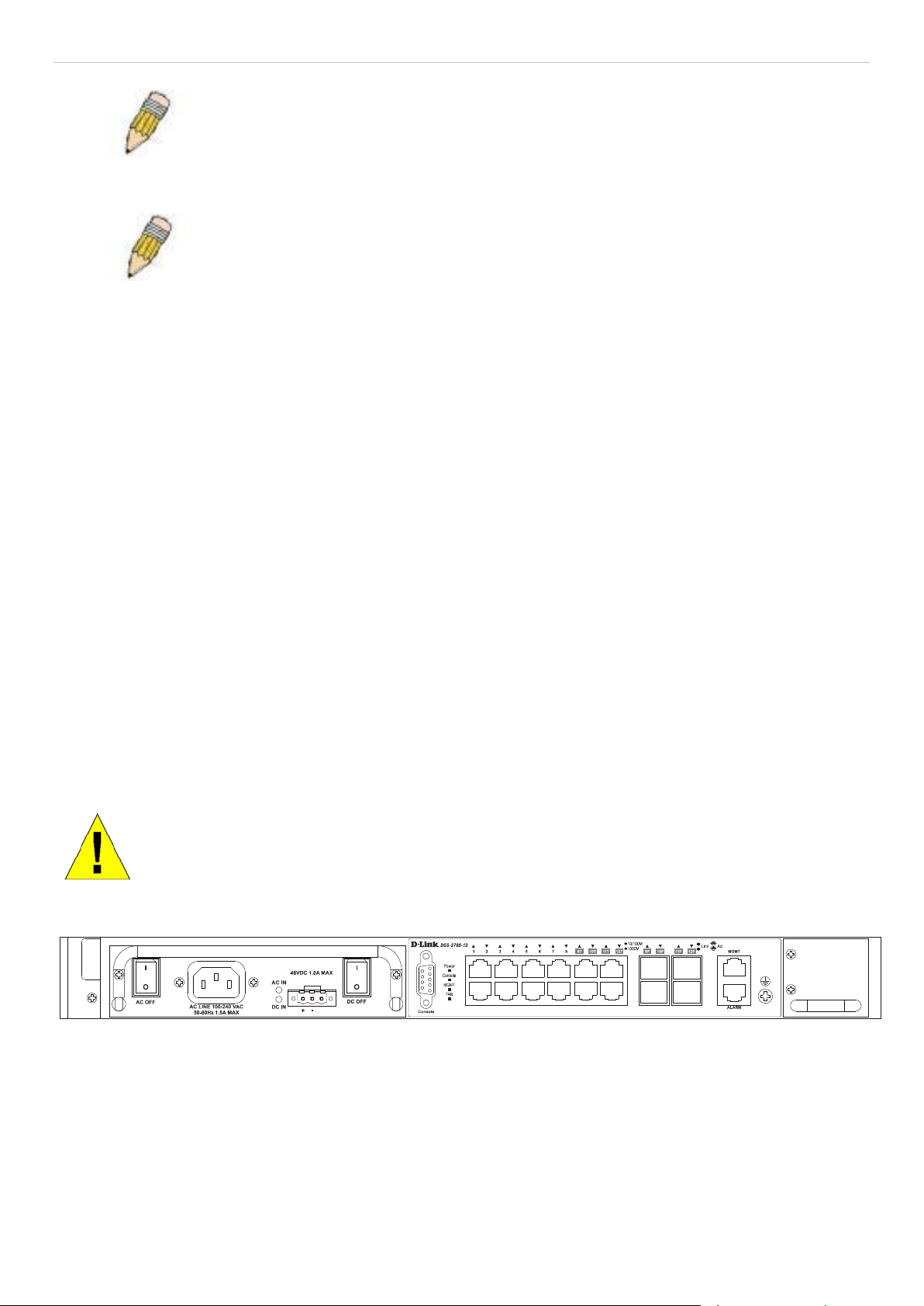
CAUTION: T he handles on the power a nd fan m odules should onl y be used to r eplace the modules in
the event of a hardware failure. Do not use the power module handle to lift the Switch.
Figure 1- 1. Front Panel View of the DGS-3700-12 switch
4
DGS-3700 Series Layer 2 Managed Gigabit Ethernet Switch Hardware Installation Guide
DES-3700-12G
• Eight 1000M SFP ports
• Four 10/100/1000BASE-T ports located to the right
• One female DCE RS-232 DB-9 console port
• One 10/100Base-Tx out of band management port
• One RJ-45 alarm port
• LEDs for AC Power, DC Power, Console, Management, Fan, Master, Link/Act/Speed for each port
• Grounding post
• Fan module
• Power module consisting of the following components:
− AC power connector (power cord provided, supports voltage 100~240 VAC at 50~60 Hz 1.5A Max)
− AC power Switch
− DC power connector (supports voltage 48VDC 1.6A Max)
− DC power switch
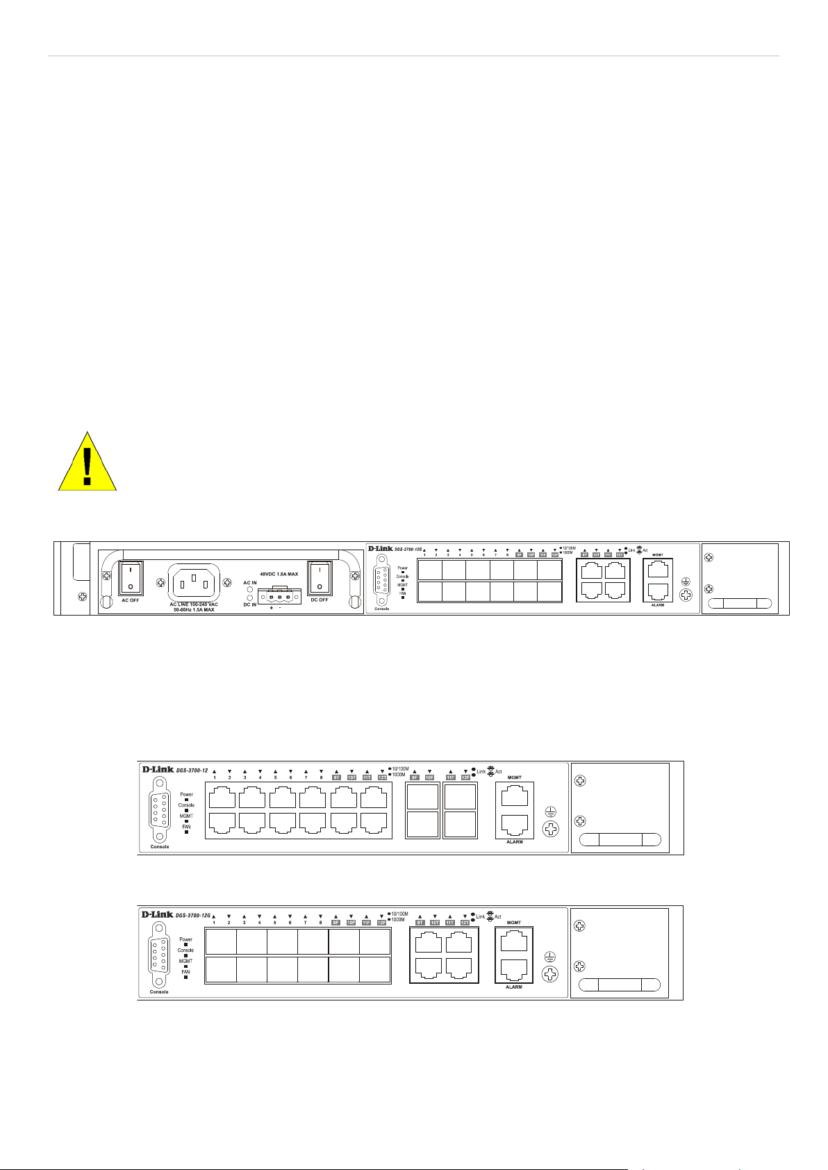
CAUTION: The ha ndles on the po wer and fan m odules should on ly be used to re place the m odules in
the event of a hardware failure. Do not use the power module handle to lift the Switch.
Figure 1- 2. Front Panel View of the DGS-3700-12G switch
LED Indicators
The Switch supports LED indicat ors for Power, Console, Manag ement, Fan and Port LEDs. T he following s hows the
LED indicators for the DG S-3700 Series along with an explanatio n of each indicator. LEDs and their correspond ing
meanings are displayed below.
Figure 1- 3. LED Indicators on DGS-3700-12 switch
Figure 1- 4. LED Indicators on DGS-3700-12G switch
5

DGS-3700 Series Layer 2 Managed Gigabit Ethernet Switch Hardware Installation Guide
LED Per 10/100/1000 Mbps
is a secure co nnection (or
link) to a 100Mbps Ethernet device on
When there is a sec ure connection (or
link) to 1000Mbps Ethernet device at
here is a reception or
Act) of data
When there is a sec ure connection (or
When there is a reception or
Act) of data
LED indicators for DGS-3700 Series
Location LED Indicative Color Status Description
Power
Solid Light Power On
Green
Light off Power Off
Solid Light Console on
Per Device
Port
Console
Management
Fan Error
Link/Act
Green
Green
Red
Green
Blinking POST is in progress
Light off Console off
Solid Light Link established
Blinking Green Ethernet activity
Light Off No cable connected
Solid Light
Light off
Solid Light
Blinking Light Link is in progress
Solid Light
When the system fan fails or the fan
module is removed
When the system fan is functioning
properly
When there
any of the ports
When there is a solid reception for
10/100M link.
SFP port (100/1000M) Link/Act
Amber
Blinking Light
Off Light off No link
Solid Light
Green
Blinking
Solid Light
Amber
Blinking
Off Light off No link
When there is a reception or
transmission (i.e. Activity—Act) of data
occurring at a Fast Ethernet connected
port
any of the ports
When t
transmis sion (i.e. Activ ity –
occurring at a port
link) to 100Mbps Ether n et dev ice at any
of the ports
transmission (i.e. Ac tivity –
occurring at a port
6
DGS-3700 Series Layer 2 Managed Gigabit Ethernet Switch Hardware Installation Guide
Rear Panel Description
The DGS-3700 Series rear panel is shown below.
Figure 1- 5. Rear panel view of the DGS-3700 Series
Side Panel Description
The left hand panel of the Switch con tains large h eat vents. T he heat vents ar e used to dis sipate heat. Do not block
these openings, and leave at least 6 inches of spac e at the rear and sides of the S witch for proper ventilation. Be
reminded that without proper heat dissipation and air circulation, system components might overheat, which could
lead to system failure. T he right-h and side pane l of the S witch conta ins three s ystem fans along with ventilati on vents
for these fans.
Figure 1- 6. Side panels of the DGS-3700 Series
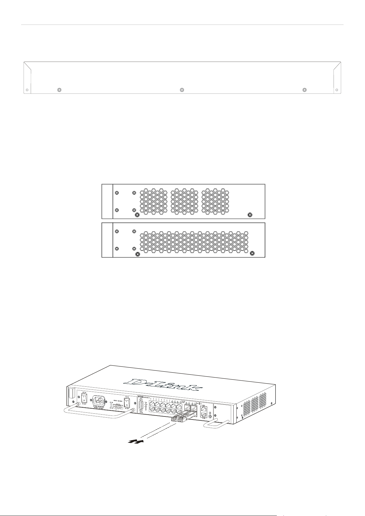
Gigabit Combo Ports
In addition to the 10/100/1000 Mbps ports, the Switch features Gigabit Ethernet Combo ports. These ports are
1000BASE-T copper por ts (pr ovided) a nd SFP p or ts ( opti ona l). S ee th e d iagr ams below to view the SFP port modules
being plugged into t he Switch. Please n ote that although these front panel modules c an be used simultan eously. At
the same time, onl y one co pper port or one SF P port c an link up f or each combo por t. The SF P port will al ways have
the highest priority.
Figure 1- 7. Inserting the SFP modules into th e DGS-3700-12
7
DGS-3700 Series Layer 2 Managed Gigabit Ethernet Switch Hardware Installation Guide
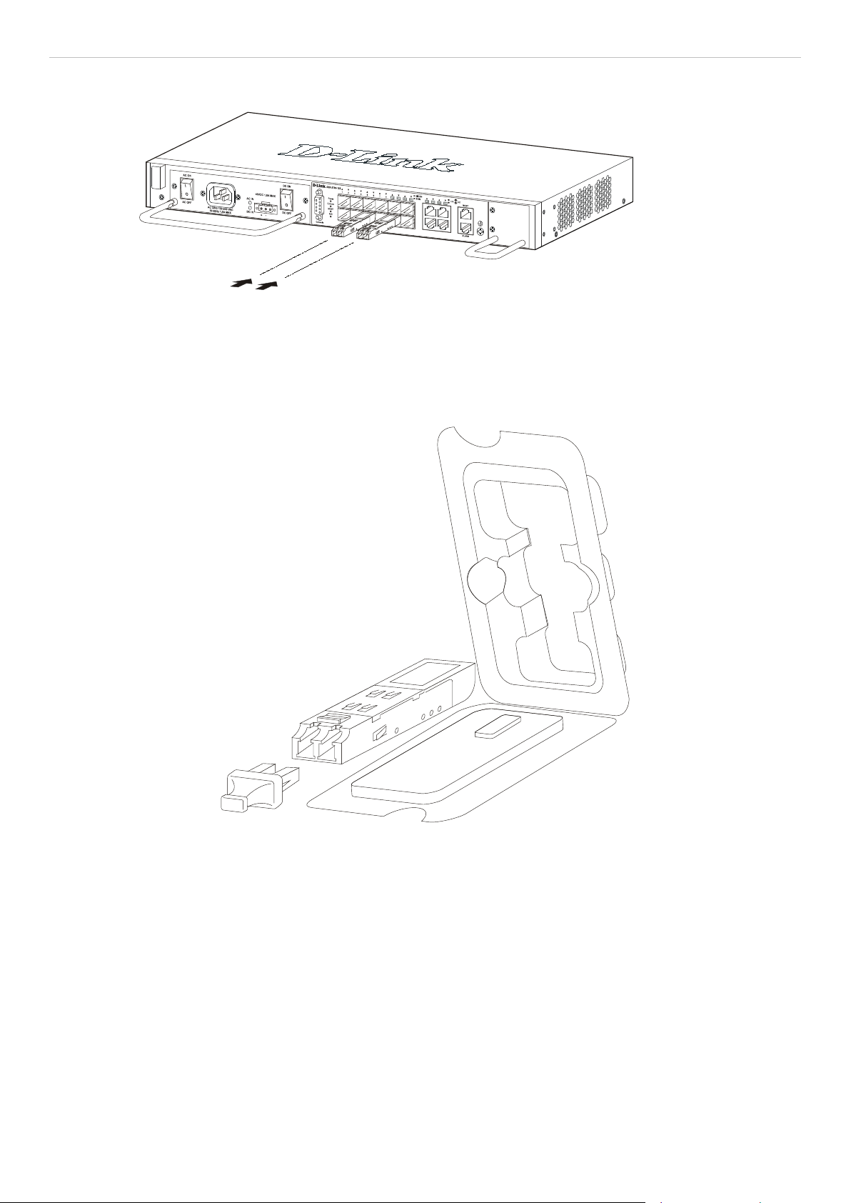
Figure 1- 8. Inserting the SFP modules into th e DGS-3700-12G
Figure 1- 9. Installing the SFP Module
The AC power connector is a standard three-pronged connector that supports the power cord. Plug-in the female
connector of the prov ided power cord into t his socket, and th e male side of the cord into a power outl et. The Switch
automatically adjusts its power setting to any suppl y voltage in the range from 100 ~ 2 40 VAC at 50 ~ 60 Hz 1.5A
Max.
The front panel also incl udes an outlet for an optiona l external DC power suppl y. See the installation instruc tions in
Section 2 for details.
8
 Loading...