

Page 1

Gigabit Ethernet Switch
Second Edition (October 2004)
6DGS3208F.02
Printed In Taiwan
DGS-3208F
User’s Guide
RECYCLABLE
Page 2

T
ABLE OF
0 ABOUT THIS GUIDE......................................................................................................................................................... V
C
ONTENTS
ERMS
.........................................................................................................................................................................................
T
VERVIEW OF THIS USER’S GUIDE
O
1 INTRODUCTION.................................................................................................................................................................1
IGABIT ETHERNET TECHNOLOGY
G
WITCHING TECHNOLOGY
S
EATURES
F
Ports........................................................................................................................................................................................ 2
Performance features.............................................................................................................................................................. 2
Management............................................................................................................................................................................3
2 UNPACKING AND SETUP.................................................................................................................................................4
NPACKING
U
ETUP
S
ESKTOP OR SHELF INSTALLATION
D
ACK INSTALLATION
R
OWER ON
P
Power Failure .........................................................................................................................................................................6
3 IDENTIFYING EXTERNAL COMPONENTS.................................................................................................................. 7
RONT PANEL
F
EAR PANEL
R
IDE PANELS
S
LED I
4 CONNECTING THE SWITCH......................................................................................................................................... 10
................................................................................................................................................................................... 2
................................................................................................................................................................................. 4
.......................................................................................................................................................................................... 4
................................................................................................................................................................................... 5
.............................................................................................................................................................................. 7
............................................................................................................................................................................... 7
............................................................................................................................................................................... 8
NDICATORS
........................................................................................................................................................................ 8
........................................................................................................................................................... 1
................................................................................................................................................................... 5
..............................................................................................................................................
.............................................................................................................................................. 1
............................................................................................................................................. 4
V
V
TO SWITCH
PC
WITCH TO SWITCH (OTHER DEVICES
S
5 SWITCH MANAGEMENT CONCEPTS.........................................................................................................................12
OCAL CONSOLE MANAGEMENT
L
Console port (RS-232 DCE).................................................................................................................................................. 12
IP Addresses and SNMP Community Names........................................................................................................................ 12
Traps .....................................................................................................................................................................................13
MIBs...................................................................................................................................................................................... 14
Packet Forwarding................................................................................................................................................................ 14
Aging Time............................................................................................................................................................................ 14
Spanning Tree Algorithm...................................................................................................................................................... 15
STA Operation Levels............................................................................................................................................................ 15
On the Bridge Level............................................................................................................................................................................... 15
On the Port Level ................................................................................................................................................................................... 16
User-Changeable Parameters............................................................................................................................................... 16
Illustration of STA................................................................................................................................................................. 16
Port Trunking........................................................................................................................................................................ 18
VLANs & MAC-based Broadcast Domains ........................................................................................................................... 19
MAC-Based Broadcast Domains........................................................................................................................................... 19
IEEE 802.1Q VLANs.............................................................................................................................................................20
802.1Q VLAN Segmentation ................................................................................................................................................................. 20
Sharing Resources Across 802.1Q VLANs ............................................................................................................................................ 20
802.1Q VLANs Spanning Multiple Switches......................................................................................................................................... 21
........................................................................................................................................................................... 10
)....................................................................................................................................... 10
............................................................................................................................................... 12
Page 3

VLANs Over 802.1Q-compliant Switches
..................................................................................................................................... 22
Port-Based VLANs ................................................................................................................................................................ 22
ROADCAST STORMS
B
................................................................................................................................................................ 23
Segmenting Broadcast Domains ...........................................................................................................................................23
Eliminating Broadcast Storms...............................................................................................................................................23
6 USING THE CONSOLE INTERFACE.................................................................................................... ........................ 25
ETTING UP
S
ONNECTING TO THE SWITCH USING TELNET
C
ONSOLE USAGE CONVENTIONS
C
IRST TIME CONNECTING TO THE SWITCH
F
A C
ONSOLE
........................................................................................................................................................... 25
............................................................................................................................ 26
............................................................................................................................................... 26
................................................................................................................................26
Steps to Create Administrator or Normal User Access......................................................................................................... 27
Administrator and Normal User Privileges........................................................................................................................... 28
Save Changes........................................................................................................................................................................ 28
OGIN ON THE SWITCH CONSOLE BY REGISTERED USERS
L
....................................................................................................... 29
Add/Modify User Account..................................................................................................................................................... 29
View/Delete User Account..................................................................................................................................................... 31
ETTING UP THE SWITCH
S
.......................................................................................................................................................... 31
System Configuration............................................................................................................................................................ 31
Configure IP Address............................................................................................................................................................................. 32
Configure Console.................................................................................................................................................................................. 33
Configure Switch.................................................................................................................................................................................... 34
Configure Ports....................................................................................................................................................................................... 35
Configure Port Mirroring ....................................................................................................................................................................... 37
Configure Spanning Tree Protocol......................................................................................................................................................... 38
Configure Filtering and Forwarding Table ............................................................................................................................................. 40
Configure Static Forwarding Table
Configure MAC Address Filtering
Configure Static Multicast Forwarding
Configure IGMP Filtering...................................................................................................................................................................... 44
Configure 802.1Q IGMP
Configure Port-based IGMP
Configure VLAN.................................................................................................................................................................................... 47
Configure MAC-based Broadcast Domains
Configure Port-based VLANs
Configure 802.1Q VLAN
Configure GMRP
.................................................................................................................................................................. 44
................................................................................................................................................................. 51
.............................................................................................................................................................................. 54
................................................................................................................................................ 41
.................................................................................................................................................. 42
.......................................................................................................................................... 43
........................................................................................................................................................... 46
................................................................................................................................. 47
......................................................................................................................................................... 50
Configure Trunk.................................................................................................................................................................... 55
Update Firmware and Configuration Files........................................................................................................................... 56
System Utilities......................................................................................................................................................................57
Ping Test................................................................................................................................................................................................. 58
Save Settings to TFTP Server................................................................................................................................................................. 59
Save Switch History to TFTP Server...................................................................................................................................................... 59
Clear Address Table ............................................................................................................................................................................... 60
SNMP Manager Configuration............................................................................................................................................. 60
WITCH MONITORING
S
................................................................................................................................................................ 61
Network Monitoring.............................................................................................................................................................. 61
Traffic Statistics...................................................................................................................................................................................... 61
Statistics Overview
Port Traffic Statistics
Port Packet Error Statistics
Port Packet Analysis Statistics
Browse Address Table ............................................................................................................................................................................ 65
Browse IGMP Status.............................................................................................................................................................................. 66
Browse GVRP Status ............................................................................................................................................................................. 67
Browse GMRP Status............................................................................................................................................................................. 68
Switch History........................................................................................................................................................................................ 68
ESETTING THE SWITCH
R
........................................................................................................................................................................... 62
........................................................................................................................................................................ 63
............................................................................................................................................................. 63
....................................................................................................................................................... 64
............................................................................................................................................................ 69
Restart System....................................................................................................................................................................... 69
Factory Reset......................................................................................................................................................................... 70
Logout ...................................................................................................................................................................................70
Page 4

7 WEB-BASED NETWORK MANAGEMENT................................................................................................... ............... 71
NTRODUCTION
I
ETTING STARTED
G
ANAGEMENT
M
.......................................................................................................................................................................... 71
.................................................................................................................................................................... 71
.......................................................................................................................................................................... 71
Configuration........................................................................................................................................................................ 72
Basic Setup.............................................................................................................................................................................................72
TCP/IP Setup.......................................................................................................................................................................................... 73
Advanced................................................................................................................................................................................................ 74
Ports Setup ............................................................................................................................................................................................. 74
Port Mirror ............................................................................................................................................................................................. 76
Trap Manager......................................................................................................................................................................................... 76
SNMP Manager...................................................................................................................................................................................... 77
Download............................................................................................................................................................................................... 78
Console................................................................................................................................................................................................... 79
Save........................................................................................................................................................................................................ 80
Reset....................................................................................................................................................................................................... 80
Bridge....................................................................................................................................................................................81
Configure Spanning Tree Protocol......................................................................................................................................................... 81
Switch STP
Port STP
Configure Filtering and Forwarding Table ............................................................................................................................................. 83
Address Setup
Custom FDB
Filter Table
802.1Q VLAN Multicast FDB
Configure IGMP Filtering...................................................................................................................................................................... 88
IGMP Setup
IGMP 802.1Q VLAN Setup
IGMP Port Based VLAN Setup
........................................................................................................................................................................................ 81
............................................................................................................................................................................................ 83
.................................................................................................................................................................................. 83
...................................................................................................................................................................................... 84
........................................................................................................................................................................................ 86
.......................................................................................................................................................... 87
....................................................................................................................................................................................... 88
............................................................................................................................................................. 89
....................................................................................................................................................... 90
Configure VLAN....................................................................................................................................................................91
Mode Setup ............................................................................................................................................................................................91
Mac-based .............................................................................................................................................................................................. 91
Port Based VLAN Setup ........................................................................................................................................................................ 93
802.1Q VLAN Configuration ................................................................................................................................................................. 94
Port VID Setup
Ingress Filtering Check
802.1Q VLAN Setup
GVRP Configuration
GMRP Configuration
GMRP Configuration............................................................................................................................................................................. 97
Device GMRP Configuration
802.1Q VLAN Multicast FDB
.................................................................................................................................................................................. 94
.................................................................................................................................................................... 94
........................................................................................................................................................................ 95
........................................................................................................................................................................ 96
........................................................................................................................................................................ 96
.......................................................................................................................................................... 97
.......................................................................................................................................................... 97
Trunk..................................................................................................................................................................................... 98
Port Trunking ......................................................................................................................................................................................... 99
Monitor.................................................................................................................................................................................. 99
Traffic Statistics.................................................................................................................................................................................... 100
Overview
Traffic
Utilization
Errors
Analysis
Browse Address Table .......................................................................................................................................................................... 105
Search By MAC
Search By Port
Search By VLAN
Search By None
IGMP Status......................................................................................................................................................................................... 107
Browse GVRP Status ........................................................................................................................................................................... 108
Browse GMRP Status........................................................................................................................................................................... 108
History Log........................................................................................................................................................................................... 109
.......................................................................................................................................................................................... 100
............................................................................................................................................................................................... 101
......................................................................................................................................................................................... 102
............................................................................................................................................................................................... 102
........................................................................................................................................................................................... 103
.............................................................................................................................................................................. 105
................................................................................................................................................................................ 105
............................................................................................................................................................................ 106
............................................................................................................................................................................. 106
User..................................................................................................................................................................................... 109
Add/Modify ..................................................................................................................... ..................................................................... 110
Utilities................................................................................................................................................................................110
Page 5

Save Settings to TFTP Server............................................................................................................................................................... 110
Save Switch History to TFTP Server.................................................................................................................................................... 111
Clear Address Table ............................................................................................................................................................................. 112
Help..................................................................................................................................................................................... 112
8 TECHNICAL SPECIFICATIONS..................................................................................................................................113
9 INDEX................................................................................................................................................................................115
Page 6

Gigabit Ethernet Switch User’s Guide
0 A
This user’s guide tells you how to install your DGS-3208F stand-alone Switch, how to connect it to your
Gigabit Ethernet network, and how to set its configuration using either the built-in console interface or Webbased management.
BOUT THIS
G
UIDE
Terms
For simplicity, this documentation uses the terms “Switch” (first lette r upper case) to refer to the DGS-3208F
Gigabit Ethernet Switch, and “switch” (first letter lower case) to refer to all Ethernet switches, including the
DGS-3208F.
Overview of this User’s Guide
Chapter 1, “
♦
Chapter 2, “
♦
Introduction
Unpacking and Setup
.” Describes the Switch and its features.
.” Helps you get started with the basic installation of the Switch.
Chapter 3, “
♦
LED indicators of the Switch.
Chapter 4, “
♦
network.
Chapter 5, “
♦
console port and other aspects about how to manage the Switch.
Chapter 6, “
♦
and monitor Switch performance and security.
Chapter 7, “
♦
browser.
Appendix A, “
♦
Identifying External Components
Connecting the Switch
Switch Management Concepts
Using the Console Interface
Web-Based Network Management
Technical Specifications
.” Tells how you can connect the DGS-3208F to yo ur Gig abit Ethern et
.” Lists the technical specifications of the DGS-3208F.
.” Describes the front panel, rear panel, side panels, and
.” Talks about local console management via th e RS-232 DCE
.” Tells how to use the built-in console interface to change, set,
.” Tells how to manage the Switch through an Internet
v
Page 7

Page 8

Gigabit Ethernet Switch User’s Guide
1
1 I
This section describes the features of the DGS-3208F, as well as giving some background information about
Gigabit Ethernet and switching technology.
NTRODUCTION
Gigabit Ethernet Technology
Gigabit Ethernet is an extension of IEEE 802.3 Ethernet utilizing the same packet structure, format, and
support for CSMA/CD protocol, full duplex, flow control, and management objects, but with a tenfold increase
in theoretical throughput over 100-Mbps Fast Ethernet and a hundredfold increase over 10-Mbps Ethernet.
Since it is compatible with all 10-Mbps and 100-Mbps Eth ernet environments, Gigabit Ethernet provide s a
straightforward upgrade without wasting a company’s existing investment in hardware, software, and trained
personnel.
The increased speed and extra bandwidth offered by Gigabit Ethernet is essential to coping with the network
bottlenecks that frequently develop as computers and their busses get faster and more users use applications
that generate more traffic. Upgrading key components, such as your backbone and servers to Gigabit Ethernet
can greatly improve network response times as well as significantly speed up the traffic between your subnets.
Gigabit Ethernet enables fast fiber-optic and copper connections to support video conferencing, complex
imaging, and similar data-intensive applications. Likewise, since data transfers occur 10 times faster than
Fast Ethernet, servers outfitted with Gigabit Ethernet NIC’s are able to perform 10 times the number of
operations in the same a mount of time.
In addition, the phenomenal bandwidth delivered by Gigabit Ethernet is the most cost-effective method to
take advantage of today and tomorrow’s rapidly improving switching and routing internetworking
technologies. And with expected advances in the coming years in silicon technology and digital signal
processing that will enable Gigabit Ethernet to eventually operate over unshielded twisted-pair (UTP) cabling,
outfitting your network with a powerful 1000-Mbps-capable backbone/server connection creates a flexible
foundation for the next generation of network technology products.
Switching Technology
Another key development pushing the limits of Ethernet technology is in the field of switching technology. A
switch bridges Ethernet packets at the MA C address level of the Ethernet protocol transmitting among
connected Ethernet or fast Ethernet LAN segments.
Switching is a cost-effectiv e way of increasing the total network capacity available to users on a local area
network. A switch increases capacity and decreases network loading by making it possible for a local area
network to be divided into different
capacity, giving a decreased load on each.
The switch acts as a high-speed selective bridge between the individual segments. Traffic that needs to go
from one segment to another is automatically forwarded by the switch, without interfering with any other
segments
which don’t compete with each other for network transmission
1
Page 9

Gigabit Ethernet Switch User’s Guide
segments. This allows the to tal network capacity to be mu ltiplied, while still main taining the same n etwork
cabling and adapter cards.
Switching LAN technology is a marked improvement over the previous generation of network bridges, which
were characterized by higher latencies. Routers have also been used to segment local area networks, but the
cost of a router and the setup and mainte nan ce re quire d make ro ute rs re lative ly impractical. To day ’s sw itche s
are an ideal solution to most kinds of local area network congestion problems.
Features
The DGS-3208F Gigabit Ethernet Switch was designed for easy installation and high performance in an
environment where traffic on the network and the number of users increase continuously.
Switch features include:
Ports
Eight 1000BASE-SX (SC-type fiber transceiver) Gigabit Ethernet ports.
♦
RS-232 DCE console port for diagnosing the Switch v ia a connection to a PC and console/out-of-band
♦
management.
Performance features
Store and forward switching scheme capability to support rate adaptation and protocol conversion.
♦
Full duplex to allow two communicating stations to transmit and receive at the same time.
♦
Data forwarding rate 1,488,100 pps per port at 100% of wire-speed for 1000-Mbps speed.
♦
Data filtering rate eliminates all erro r packets, runts, etc. at 1,488,100 pps per port at 100% of wire-
♦
speed for 1000-Mbps speed.
12K active MAC address entry table per device with automatic learning and aging.
♦
16 MB packet buffer per device.
♦
Supports broadcast storm rate filtering.
♦
Supports IGMP snooping.
♦
Supports port mirroring.
♦
Supports GVRP.
♦
Supports GMRP (802.1P).
♦
Supports 802.1P priority (tag mode).
♦
Supports static filtering (based on MAC Address)
♦
Supports port-based VLAN (overla pping VLANs are excluded).
♦
Supports IEEE 802.1Q VLAN.
♦
2
Page 10

Gigabit Ethernet Switch User’s Guide
Supports Link Aggregation Capability.
♦
Management
RS-232 console port for out-of-band management via a PC.
♦
IEEE 802.1d Spanning Tree Algorithm Protocol for creation of alternative backup paths and pre vention
♦
of indefinite network loops.
Fully configurable either in-band or out-of-band control via SNMP based software.
♦
Flash memory for software upgrade. This can be done in-ban d via BOOTP/TFTP. Out-of-band con sole
♦
can also initiate a download request.
Built-in SNMP management: Bridge MIB (RFC 1493), RMON MIB (RFC 1757), MIB-II (RFC 1213),
♦
VLAN MIB (802.1Q), 802.1D MIB, and D-Link proprietary MIB.
3
Page 11

Gigabit Ethernet Switch User’s Guide
2
2 U
This chapter provides unpacking and setup information for the Switch.
NPACKING AND SETUP
Unpacking
Open the shipping carton of the Switch and carefully unpack its contents. The carton should contain the
following items:
One DGS-3208F Gigabit Ethernet Switch
♦
Accessory pack: 2 mounting brackets and screws
♦
Four rubber feet with adhesive backing
♦
One AC power cord
♦
This user’s guide on CD-ROM
♦
If any item is found missing or damaged, please contact your local D-Link reseller for replacement.
Setup
The setup of the Switch can be performed using the following steps:
The surface must support at least 5 kg.
♦
The power outlet should be within 1.82 meters (6 feet) of the device.
♦
Visually inspect the power cord and see that it is secured fully t o the AC power connector.
♦
Make sure that there is proper heat dissipation from and adequate ventilation around the Switch. Do
♦
not place heavy objects on the Switch.
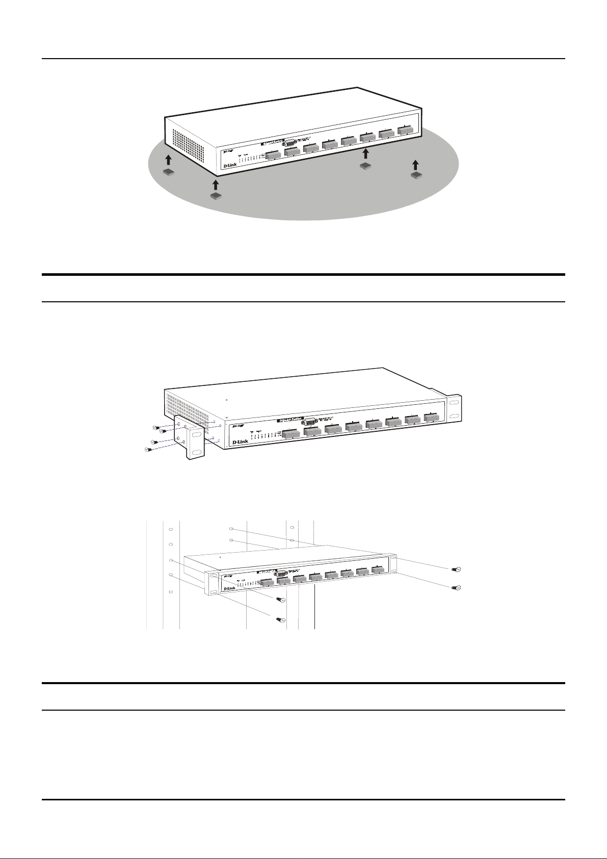
Desktop or Shelf Installation
When installing the Switch on a desktop or shelf, the rubber feet included with the device must be first
attached. Attach these cushioning feet on the bottom at each corner of the device. Allow enough ventilation
space between the device and the objects around it.
4
Page 12
Gigabit Ethernet Switch User’s Guide
Figure 2-1. Gigabit Ethernet Switch installed on a Desktop or Shelf
Rack Installation
The DGS-3208F can be mounted in an EIA standard size, 19- inch rack, which can be placed in a wiring close t
with other equipment. To install, attach the mounting brackets on the switch’s front panel (one on each side)
and secure them with the screws provided.
Figure 2- 2A. A ttaching the mounting brackets to the Switch
Then, use the screws provided with the equipment rack to mount the Switch in the rack.
Figure 2-2B. Installing the Switch in an equipment rack
Power on
The DGS-3208F Switch can be used with AC power so urces 100 ~ 240 VAC, 50 ~ 60 Hz. The Switch’s pow er
supply will adjust to the local p ower source automatically and may be turned o n without having any or all
LAN segment cables connected.
5
Page 13

Gigabit Ethernet Switch User’s Guide
After the device is powered on, the LED indicators should respond as follows:
The Power LED indicator will light wh ile the Switch loads onboard software, and should re main on as
♦
long as the switch has power.
The Console LED indicator will remain ON if there is a connection at the RS-232 port, otherwise this
♦
LED indicator is
OFF
.
Power Failure
As a precaution, the Switch should be unplugged in case of p ower failure. When powe r is resumed, plug the
Switch back in.
6
Page 14
Gigabit Ethernet Switch User’s Guide
3
3 I
This chapter describes the front panel, rear panel, side panels, and LED indicators of the Switch
DENTIFYING EXTERNAL
C
OMPONENTS
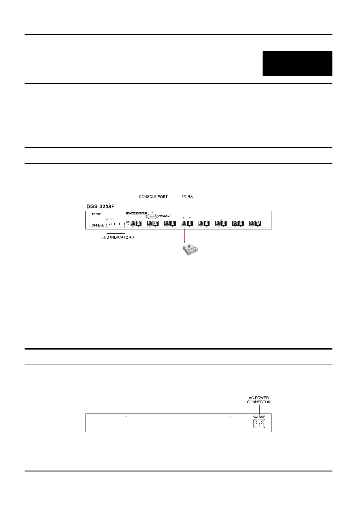
Front Panel
The front panel of the Switch consists of eight 1000BASE-SX (SC-type) multimode fiber ports, an RS-232
communication port, and LED indicators.
Figure 3-1. Front panel view of the DGS-3208F Switch
Eight Gigabit Ethernet ports of fixed 1000BASE-SX multimode fiber interface for connections to
♦
workstations, servers, and networking devices through multimode optical fiber cabling.
An RS-232 DCE console port is for diag nosing the Switch via a connection to a PC and local console
♦
management.
Comprehensive LED indicators display the condition of the Switch and status of the network. A
♦
description of these LED in dicators follows (see
LED Indicators
).
Rear Panel
The rear panel of the Switch consists of an AC power connector. The following shows the rear panel of the
Switch.
Figure 3-2. Rear panel view of the DGS-3208F
7
Page 15
Gigabit Ethernet Switch User’s Guide
♦ AC Power Connector
female connector of the provided power cord into this connector, and the male into a power outlet.
Supported input voltages range from 100 ~ 240 VAC at 50 ~ 60 Hz.
This is a three-pronged connector that supports the power cord. Plug in the
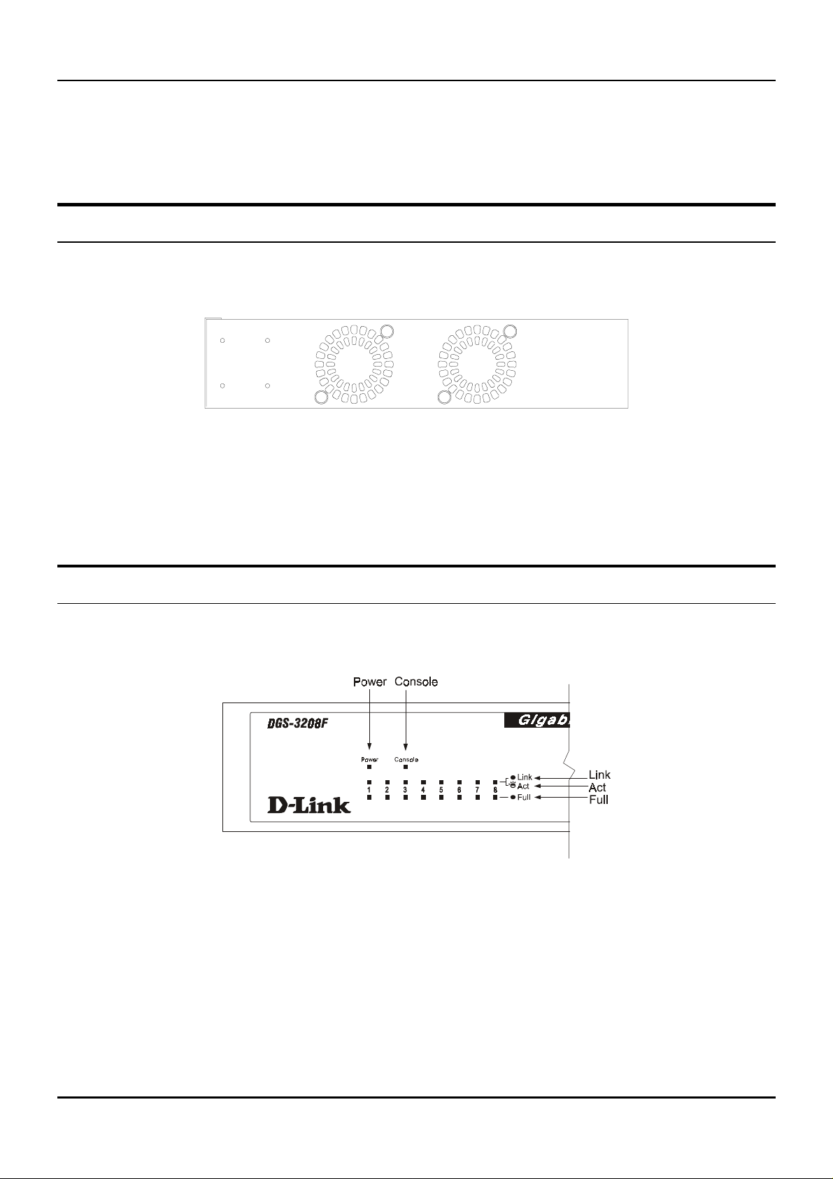
Side Panels
The Switch’s side panels contain the system fans, two on the right and one on th e left. The following shows the
Switch’s right side panel.
Figure 3-3. Right side panel view of the DGS-3208F
♦ System Fans
serve the same purpose. Be sure not to block these openings, and to leave adequate space at the rear
and sides of the Switch for proper ventilation. Remember that without proper heat dissipation and air
circulation, system components might overheat, which could lead to system failure.
These fans are used to dissipate heat. The sides of the system also provide heat vents to
LED Indicators
The LED indicators of the Switch include Power, Console, Link/ACT, and Full. The following shows the LED
indicators for the Switch along with an explanation of each indicator.
Figure 3-4. The DGS-3208F Switch LED indicators
♦ Power
Switch is loading onboard so ftware. This indicato r should then re main on to indicate the ready state of
the Switch.
♦ Console
management through the RS-232 console port using a straight-through serial cable. When a secured
connection is established, this LED indicator is lit. Otherwise, it remains dark.
After turning on the powe r, the Powe r indicator on the front panel sho uld light to indic ate the
This LED indicator is lit when the Switch is being managed via out-of-band/local console
8
Page 16

Gigabit Ethernet Switch User’s Guide
♦ Link/ACT
These LED indicators are lit when there is a secure connection (or link) to a device at any of
the ports. The LED indicators blink whenever there is reception or transmission (i.e. Activity—ACT) of
data occurring at a port.
♦ Full
These LED indicators are illuminated when a port is operating in full-duplex mode.
9
Page 17
Gigabit Ethernet Switch User’s Guide
4
4 C
This chapter describes how to connect the DGS-3208F to your Gigabit Ethernet network.
ONNECTING THE SWITCH
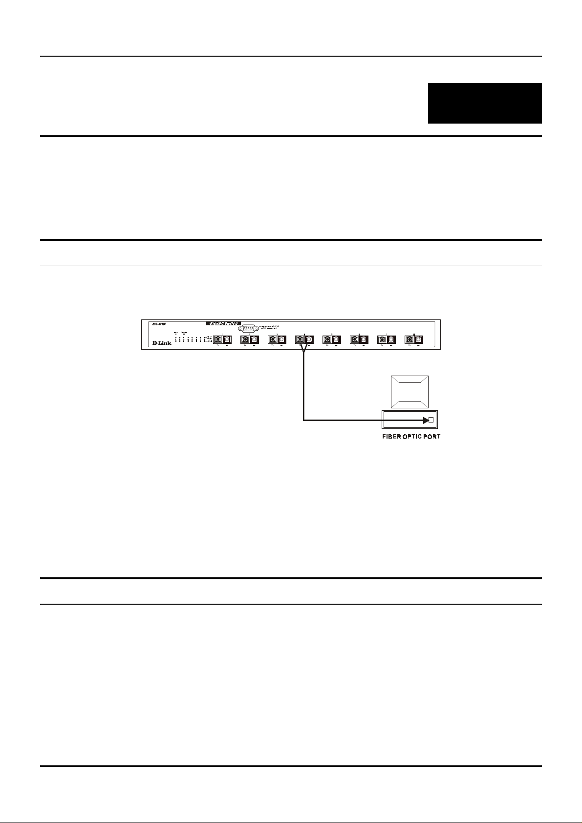
PC to Switch
A PC can be connected to the Switch via a fiber optic cable. The PC should be connected to any of the eight
ports (1x – 8x) of the DGS-3208F.
Figure 4-1. DGS-3208F Switch connected to a PC or Workstation (full-duplex mode is required)
The LED indicators for PC connection are de pendent on the LAN card capabilities. If LED indicators are not
illuminated after making a proper connection, check the PC’s LAN card, the cable, Switch conditions, and
connections.
The following is an LED indicator possibility for a PC to Switch connection:
The Link/ACT LED indicator lights up upon hookup.
♦
Switch to Switch (other devices)
The Switch can be connected to another switch or other devices (routers, bridges, etc.) via a fiber optic cable.
10
Page 18
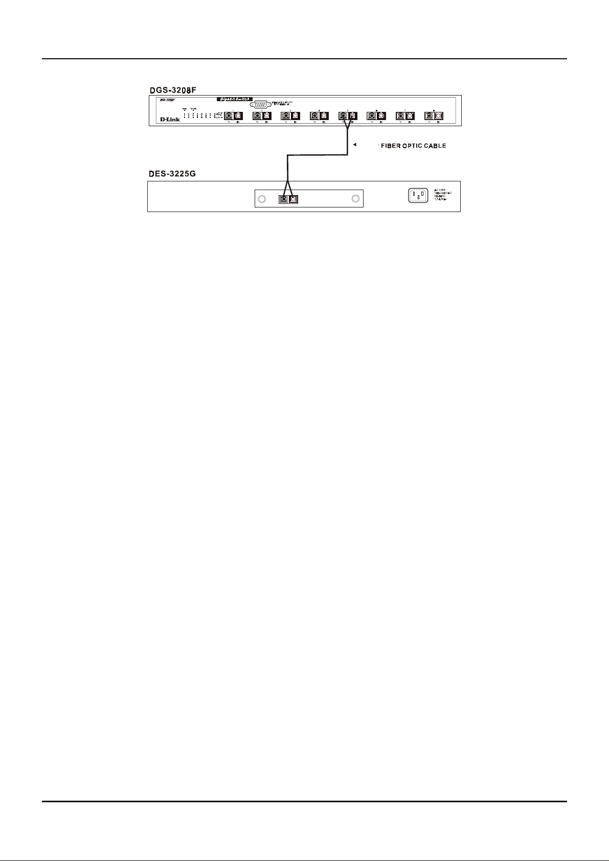
Figure 4-2. DGS-3208F Switch to switch connection.
Gigabit Ethernet Switch User’s Guide
11
Page 19

Gigabit Ethernet Switch User’s Guide
5
5 S
WITCH
M
ANAGEMENT
C
ONCEPTS
Local Console Management
Local console management involves the administration of the DGS-3208F Switch via a direct connection to the
RS-232 DCE console port. From the Main Menu screen of the console pr ogram, an Administrator or N ormal
User (defined in the next chapter) has privilege and access to manage, control, and monitor the many
functions of the Switch.
The components of the Switch allow them to be part of a manageable network. These components include a
CPU, memory for data storage, other related hardware, and the SNMP agent firmware. Activities on the
Switch can be monitored with these components, while the Switch can be manipulated to carry out specific
tasks.
Out-of-band management for the Switch is accomplished through a locally connected management terminal to
the RS-232 console port. Through this port, a user can set up, monitor, or change the configuration of the
Switch.
The Spanning Tree Algorithm (STA) provides the capability for the Switch to operate properly with other
Bridges in a SNMP networ k supporting th e STA. Using the STA, th e network w ill prevent n etwork loo p, and
automatically establish and activate a backup path in the event of a path failure.
Console port (RS-232 DCE)
Out-of-band management requ ires connecting a PC (with a SNMP manag ement platform) to the RS-232 DC E
console port of the Switch . Switch management using terminal emulation/VT100 when co nnected to the RS232 DCE console port is called
management platforms.
The console port is set for the following configuration:
Baud rate: 9,600
◊
Parity: none
◊
Data width: 8 bits
◊
Stop bits 1
◊
Local Console Management
to differentiate it from management done via
IP Addresses and SNMP Community Names
Each Switch has its own IP Address, which is used for communication with an SNMP network manager or
other TCP/IP application ( for exam ple BO OTP, TFTP). Yo u can c hange the defa ult Switch IP Addr ess to m eet
the specification of your networking address scheme.
12
Page 20

Gigabit Ethernet Switch User’s Guide
In addition, you can also set in the Switch an IP Address for a gateway or a router. It is useful when the
management station is not located on the same network as the Switch, making it necessary for the Switch to
go through a gateway or router to reach the network manager.
For security, you can set in the Switch a list of IP Addresses of the network managers that you allow to
manage the Switch . You can also ch ange the d efault Comm unity Name in the Switch an d set access rig hts of
these Community Names.
Traps
Trap managers are special users of the network who are given certain rights and access in overseeing the
maintenance of the network. Trap managers can receive traps sent from the Switch; they must immediately
take certain actions to avoid future failure or break down of the network.
Traps are messages that alert you of events that occur on the Switch. The events can be as serious as a reboot
(someone accidentally turned
traps and sends them to the n etwork manager (trap man agers). The following lists the types of events that
can take place on the Switch.
System resets
◊
the Switch), or less serious like a port status change. The Switch generates
OFF
Errors
◊
Status changes
◊
Topology changes
◊
Operation
◊
You can also specify which network managers may receive traps from the Switch by setting a list of IP
Addresses of the authorized network managers.
The following are trap types a trap manager will receive:
♦ Cold Start
settings are reconfigured and hardware systems are rebooted. A cold start is different from a factory
reset.
♦ Warm Start
Test) is skipped.
♦ Authentication Failure
a valid user of the Switch and may have entered an incorrect community name.
♦ New Root
is sent by a bridge soon after its election as the new root. This implies that upon expiration of the
Topology Change Timer th e new root trap is sent out immediate ly after the Switch ’s selection as a new
root.
This trap signifies that the Switch has been powe red up and initialize d such that softw are
This trap signifies that the Switch has been rebooted, however the POST (Power On Self-
This trap signifies that an addressee (or manager/user) on the Switch is not
This trap indicates that the Switch has become the new root of the Spanning Tree, the trap
♦ Topology Change
transitions from the Learning state to the Forwarding state, or from the Forwarding state to the
Blocking state. The trap is not sent if a new root trap is sent for the same transition.
♦ Link Change Event
from link down to link up.
A Topology Change trap is sent by the Switch when any of its configured ports
This trap is sent whenever the link of a port changes from link up to link down or
13
Page 21

Gigabit Ethernet Switch User’s Guide
MIBs
The information stored in the Switch is known as the Management Information Base (MIB). The Switch uses
the standard MIB-II Management Information Base module. Consequently, MIB values inside the Switch can
be retrieved from any SNMP-based network manager. In addition to the standard MIB-II, the Switch also
supports its own proprietary enterprise MIB as an extended Management Information Base. These MIBs may
also be retrieved by specifying the MIB’s Object-Identity (OID) at the network manager. MIB values can be
either read-only or read-write.
Read-only MIBs variables can be either constants that are programmed into the Switch, or variables that
change while the Switch is in operation. Examples of read-only constants are the number of ports and types
of ports. Examples of read-only variables are the statistics counters such as the number of errors that have
occurred, or how many kilobytes of data have been received and forwarded through a port.
Read-write MIBs are variables usually related to user-customized configurations. Examples of these are the
Switch’s IP Address, Spanning Tree Algorithm parameters, and port status.
If you use a third-party vendors’ SNMP software to manage the Switch, a diskette listing the Switch’s
propriety enterprise MIBs can be obtained by request. If your software provides functions to browse or modify
MIBs, you can also get the MIB values and change them (if the MIBs’ attributes permit the write operation).
This process however can be qu ite involved, since you must k now the MIB OIDs and retrieve them one by one.
Packet Forwarding
The Switch looks at the network configuration to forward packets. This reduces the traffic congestion on the
network, because packets, instead of being transmitted to all segments, are transmitted to the destination
only. Example: if Port 1 receives a packet destined for Port 2, the Switch transmits that packet through Port
2 only, and transmits nothing through Port 1.
♦ Filtering Database
other ports on that Switch, in order to prevent the duplication of frames. Frames transmitted between a
pair of end stations can be confined to LANs that form a path between those end stations.
The functions that support the use and maintenance of filtering database information are:
Permanent configuration of reserved addresses.
1.
Explicit configuration of static filtering information.
2.
Automatic learning of dynamic filtering information through observation of Switched Local Area
3.
Network traffic.
Aging out of filtering information that has been automatically learned.
4.
Calculation and configuration of Switched Local Area Network topology.
5.
A Switch filters frames, i.e., does no t relay frames received by a Switch port to
Aging Time
The Aging Time is a parameter that affects the auto-learn process of the Switch in terms of the network
configuration. Dynamic Entries, which make up the auto-learned-node address, are aged out of the address
table according to the Aging Time that you set.
The Aging Time can be from 1 to 99 minutes. A very long Aging Time can result with the out-of-date Dynamic
Entries that may cause incorrect packet filtering/forwarding decisions .
14
Page 22

Gigabit Ethernet Switch User’s Guide
In the opposite case, if the Aging Time is too short, many entries may be aged out soon, resulting in a high
percentage of received packets whose source addresses cannot be found in the address table.
Spanning Tree Algorithm
The Spanning Tree Algorithm (STA) in the Switch allows you to create alternative paths (with multiple
switches or other types of bridges) in your network. These backup paths are idle until the Switch determines
that a problem has developed in the primary path s. When a primary path is lost, the switch providing the
alternative path will automatically go into service with no operator intervention. This automatic network
reconfiguration provides maximum uptime to network users. The concept of the Spanning Tree Algorithm is a
complicated and complex subject and must be fully researched and understood. Please read the following
before making any changes.
♦ Network loop detection and prevention
LANs. If there is more than one path, forwarded packets will lo op indefin itely. STA detects any looped
path and selects the path with the lowest path cost as the activ e path , w hile blo ckin g th e o the r p ath an d
using it as the backup path.
♦ Automatic topology re-configuration
backup path will be automatically activated, and STA will automatically re-configure the network
topology.
With STA, there will be only one path between any two
When the path for which there is a backup path fails, the
STA Operation Levels
STA operates on two le vels: the bridge leve l and the port le vel. On the bridge le vel, STA calculate s the Bridg e
Identifier for each Switch, then sets the Root Bridge and the Designated Bridges. On the port level, STA sets
the Root Port and Designated Ports. Details are as follows:
On the Bridge Level
♦ Root Bridge
the Root Bridge to be the best switch among the switches in the loop to ensure the highest network
performance and reliability.
♦ Bridge Identifier
the MAC address of the sw itch. Example: 4 00 80 C8 00 01 00, whe re 4 is the Bridge Priority. A lower
Bridge Identifier results in a higher priority for the switch, and thus increases it probably of being
selected as the Root Bridge.
The switch with the lowe st Bridge Identif ier is the Ro ot Brid ge. Naturally , yo u w ill w ant
This is the combination of the Bridge Priority (a parameter that you can set) and
♦ Designated Bridge
to the Root Bridge is the Designated Bridge. It forwards data packets for that LAN segment. In cases
where all Switches have the same Root Path Cost, the switch with the lowest Bridge Identifier becomes
the Designated Bridge.
♦ Root Path Cost
Root Path Costs of all the switches that the packet goes through. The Root Path Cost of the Root Bridge
is zero.
♦ Bridge Priority
the Bridge Priority is. The higher the Bridge Priority, the better the chance the Switch will be selected
as the Root Bridge.
From each LAN segment, the attached Bridge that has the lowest Root Path Cost
The Root Path Cost of a switch is the sum of the Path Cost of the Root Port and the
This is a parameter that use rs can set. The smaller the n umber you set, the higher
15
Page 23

Gigabit Ethernet Switch User’s Guide
On the Port Level
♦ Root Port
Bridge. In case there are several such ports, then the one with the lowest Port Identifier is the Root
Port.
♦ Designated Port
which the switch is the Designated Bridge.
♦ Port Priority
higher the probability that the port will be selected as the Root Port.
♦ Path Cost
Each switch has a Root Port. This is the port that has the lowest Path Cost to the Root
This is the port on each Designated Bridge that is attached to the LAN segment for
The smaller this number, the higher the Port Priority is. With higher Po rt Priority, the
This is a changeable parameter and may be modified according to the STA specification.
User-Changeable Parameters
The factory default setting should cover the majority of installations. However, it is advisable to keep the
default settings as set at the factory, unless it is absolutely necessary. The user-changeable parameters in the
Switch are as follows:
♦ Bridge Priority
♦ Bridge Hello Time
transmissions of BPDU packets sent by the Root Bridge to tell all other Switches that it is indeed the
Root Bridge. If you set a He llo Time for your Switch, and it is not the Root Bridge, the set Hello Time
will be used if and when you r Switch becomes the Root Bridge. (Note that the Hello Time cannot be
longer than the Max. Age. Otherwise, a configuration error will occur).
A Bridge Priority can be from 0 to 65535. 0 is equal to the highest Bridge Priority.
The Hello Time can be fro m 1 to 10 seconds. This is the inte rval between two
♦ Bridge Max. Age
has still not been received from the Root Bridge, yo ur Switch will start sending its own BPDU to all
other Switches for permission to become the Root Bridge. If it turns out that your Switch has the lowest
Bridge Identifier, it will become the Root Bridge.
♦ Bridge Forward Delay
the Switch spends in th e listening state while moving from the blocking sta te to the forwarding state.
Observe the following formulas when you set the above parameters:
♦ Port Priority
1. Max. Age = 2 x (Forward Delay - 1 second)
2. Max. Age = 2 x (Hello Time + 1 second)
the port will be chosen as the Root Port.
The Max. Age can be from 6 to 40 seconds. At the end of the Max. Age, if a BPDU
The Forward Delay can be from 4 to 30 second s. This is the time any p ort on
A Port Priority can be from 0 to 255. The lower the number, the g reater the pr obability
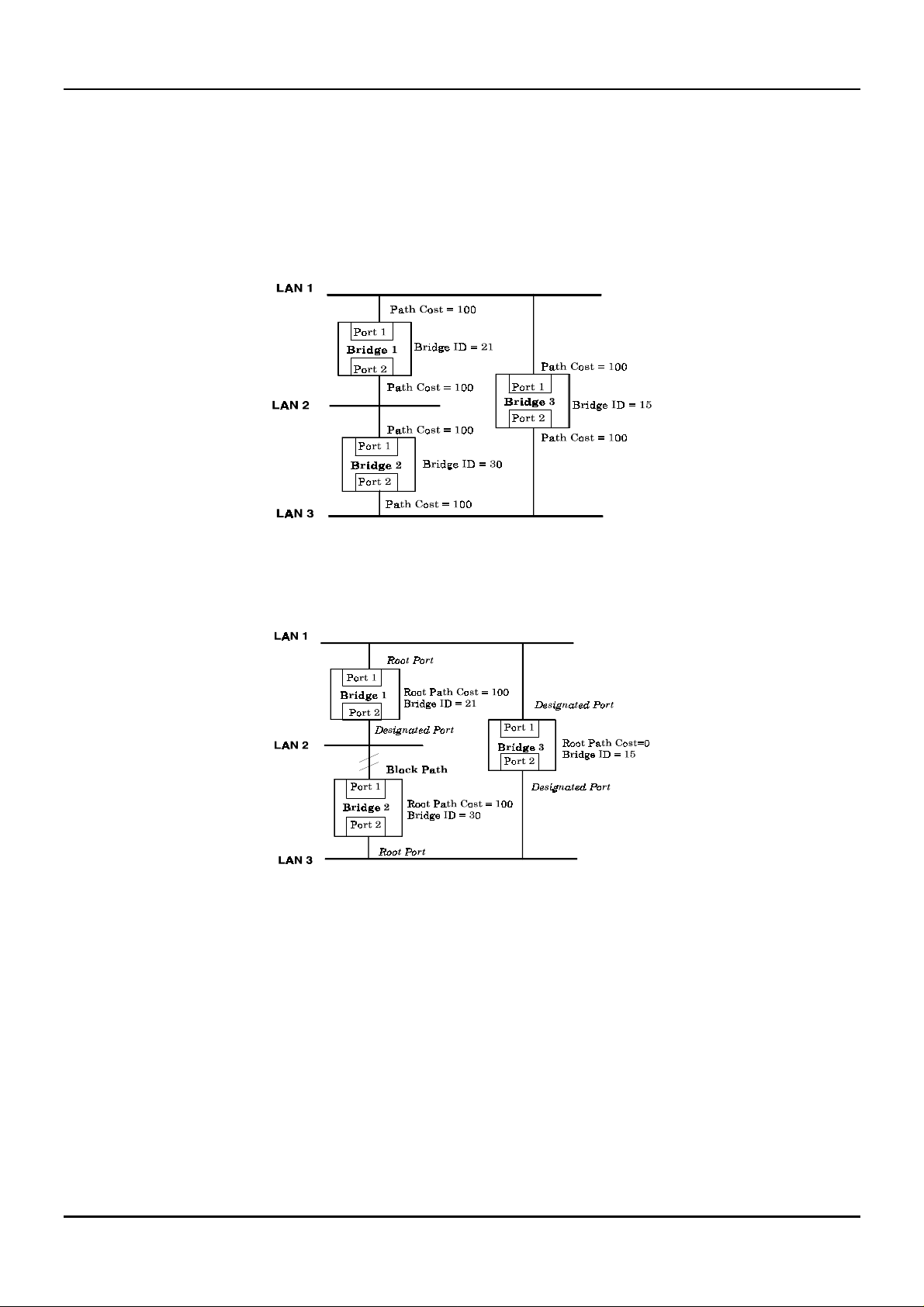
Illustration of STA
A simple illustration of three Bridg es (or the Switch) connected in a loop is depicted in
example, you can anticipate some major network problems if the STA assistance is not applied. For instance,
if Bridge 1 broadcasts a packet to Brid ge 2, Brid ge 2 will bro adcast it to Bridge 3, Brid ge 3 will broadcast it to
Bridge 1, and so on. The broadcast packet will be passed indefinitely in a loop, causing a serious network
failure.
Figure 5-1
. In this
To alleviate network loop problems, STA can be applied as shown in
the loop by blocking the connection between Bridge 1 and 2. The decision to block a particular connection is
16
Figure
5-2. In this example, STA breaks
Page 24
Gigabit Ethernet Switch User’s Guide
based on the STA calculation of the most current Bridge and Port settings. Now, if Bridge 1 broadcasts a
packet to Bridge 3, then Bridge 3 will broadcast it to Bridge 2 and the broadcast will end there.
STA setup can be somewhat complex. Therefore, you are advised to keep the default factory settings and STA
will automatically assign root bridges/ports and block loop connectio ns. Howeve r, if you n eed to cu stomize the
STA parameters, refer to
Table 5-1
.
Figure 5-1. Before Applying the STA Rules
Figure 5-2. After Applying the S TA Rules
17
Page 25
Gigabit Ethernet Switch User’s Guide
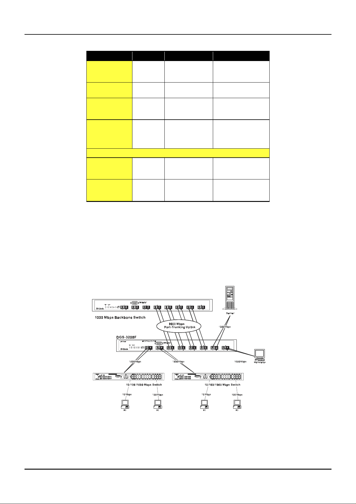
STA parameters Settings Effects Comment
Port Trunking
Bridge Priority
Hello Time
Max. Age Time
Forward Delay
Enable/Disable
Port Priority
Table 5-1. User-selective STA parameters
lower the #,
higher the
priority
1 - 10 sec. No effect, if not
6 - 40 sec. Compete for Root
4 - 30 sec. High # delays the
Port-level STA parameters
Enable/
Disable
lower the #,
higher the
priority
Increases chance of
becoming the Root
Bridge
Root Bridge
Bridge, if BPDU is
not received
change in state
Enable or disable
this LAN segment
Increases chance of
become Root Port
Avoid, if the switch is
used in workgroup level
of a large network
Never set greater than
Max. Age Time
Avoid low number for
unnecessary reset of
Root Bridge
Max. Age ≤ 2 x
(Forward Delay - 1)
Max. Age ≥ 2 x (Hello
Time + 1)
Disable a port for
security or problem
isolation
Port trunking is used to combine a number of ports togethe r to make a single hig h-bandwidth data pipeline.
The participating parts are called members of a trunk group.
The Switch supports up to four trunk groups, the first three which may include from two to four switch ports
each. The fourth trunk group is two ports only.
Figure 5-3. Port trunking example
The switch treats all ports in a trunk group as a single port. As such, trunk ports will no t be blocked by the
spanning tree algorithm.
18
Page 26

Gigabit Ethernet Switch User’s Guide
Data transmitted to a specific host (de stination address) will always be transmitted over the same port in a
trunk group. This allows packets in a data stream to arrive in the same order they were sent. A trunk
connection can be made with any other switch that maintains host-to-host data streams over a single trunk
port. Switches that use a load-balancing scheme that sends the packets of a host-to-host data stream over
multiple trunk ports cannot have a trunk connection with the Switch.
VLANs & MAC-based Broadcast Domains
VLANs are a collection of users or switch ports grouped together in a secure, autonomous broadcast and
multicast domain. The main purpose of setting up VLANs or a broadc ast domain on a netwo rk is to limit the
range and effects of broadcast packets.
Two types of VLANs are implemented on the Switch: 802.1Q VLANs and port-based VLANs. MAC-based
broadcast domains are a third option. Only one type of VLAN or broadcast domain can be active on the Switch
at any given time, however. Thus, you will need to ch oose the typ e of VLAN or bro adcast domain you wish to
setup on your network and configure the Switch accordingly. 802.1Q VLANs support IEEE 802.1Q tagging,
which enables them to span the entire network (assuming all switches on the network are IEEE 802.1Qcompliant). In contrast, MAC-based broadcast domains are limited to the Switch and devices directly
connected to them.
All VLANs allow a network to be segmented in order to reduce the size of broadcast domains. All broadcast,
multicast, and unknown packets entering the Switch on a particular VLAN will only be forwarded to the
stations or ports (802.1Q and port-based ) that are members o f that VLAN . 802.1Q and p ort-base d VLANs also
limit unicast packets to members of the VLAN, thus providing a degree of security to your network.
Another benefit of 802.1Q and port-based VLANs is that you can change the network topology without
physically moving stations or changing cable connections. Stations can be ‘moved’ to another VLAN and thus
communicate with its membe rs and share its re sources, simp ly by chang ing the po rt VLAN setting s from one
VLAN (the sales VLAN, for example) to another VLAN (the marketing VLAN). This allows VLANs to
accommodate network moves, changes and additions with the utmost flexibility. MAC-based broadcast
domains, on the other hand, allow a station to be physically moved yet still belong to the same broadcast
domain without having to change and configuration settings.
The
untagging
recognize VLAN tags in packet headers. The
switches through a single physical connection and allows Spanning Tree to be enabled on all ports and work
normally (BPDU packets are not tagged).
feature of IEEE 802.1Q VLANs allows VLANs to work with legacy switches that don’t
tagging
feature allows VLANs to span multiple 802.1Q-compliant
MAC-Based Broadcast Domains
The Switch supports up to 12 MAC-base d broad cast domain s, which are by their n ature, limite d to the Switch
itself and the devices connected directly to it.
Since MAC addresses are hard-wired into a station’s network interface card (NIC), MAC-based broadcast
domains enable network managers to move a station to a different physical location on the network and have
that station automatically retain its broadcast domain membe rship. This provides the network with a hig h
degree of fle xibility since e ven no tebook PC’s can p lug into any available port o n a n etwork and co mmunicate
with the same people and use the same resources that have been allocated to the broadcast domain in which it
is a member.
Since MAC-based broadcast domains do not restrict the transmission of known unicast frames to other
broadcast domains, they can only be used to define limited broadcast domains. As such, they are best
implemented on networks where stations are frequently moving, for example where people using notebook
PCs are constantly plugging into different parts of the network.
19
Page 27
Gigabit Ethernet Switch User’s Guide
Setting up MAC-based broadcast domains is a relatively straightforward process. Simp ly create the broadcast
domain by assigning it a name (description) and add MAC addresses for the stations that will be members.
IEEE 802.1Q VLANs
The Switch supports abou t 2000 802.1Q VLANs. 802.1Q VLANs limit traffic that f lows into and o ut of switch
ports. Thus, all devices connected to a port are members of the VLAN(s) the port belongs to, whether there is a
single computer directly connected to a switch, or an entire department.
On 802.1Q VLANs, NICs do not n eed to be able to identify 802.1Q tags in packet headers. NICs send and
receive normal Ethernet packets. If the packet’s destination lies on the same segment, communications take
place using normal Ethernet protocols. Even though this is always the case, when the destination for a packet
lies on another Switch port, VLAN considerations come into play to decide if the packet gets dropped by the
Switch or delivered.
There are two key comp onents to unde rstanding 802.1Q VLANs: Po rt VLAN ID numbe rs (PVIDs) and VLAN
ID numbers (VIDs). Both v ariables are assigne d to a sw itch port, but there are importan t dif fere nces betwee n
them. A user can only assign one PVID to each switch port. The PVID defines which VLAN a packet belongs
to when packets need to be forwarded to another switch port or somewhere else on the network. On the other
hand, a user can define a port as a member of multiple VLANs (VIDs), allowing the segment connected to it to
receive packets from many VLANs on the ne tw or k. The se tw o v ariable s con trol a p ort’s ability to transmit an d
receive VLAN traffic, and the differenc e between them provides network se gmentation, while still allowing
resources to be shared across more than one VLAN.
802.1Q VLAN Segmentation
The following example is h elpful in explainin g how 802.1Q VLAN seg mentation works. Take a p acket that is
transmitted by a machine on Port 7 that is a member of VLAN 2 and has the Port VLAN ID number 2
(PVID=2). If the destination lies on another port (found through a normal forwarding table lookup), the
Switch then looks to see if the other port (Port 4) is a member of VLAN 2 (and can therefore receive VLAN 2
packets). If port 4 is not a member of VLAN 2, then the packet will be dro pped by the Switch and will not
reach its destination. If Port 4 is a membe r of VLAN 2, the packe t will go th rough. This se lective forward ing
feature based on VLAN criteria is how VLANs segment networks. The key point being that Port 7 will only
transmit on VLAN 2, because it’s Port VLAN ID number is 2 (PVID=2).
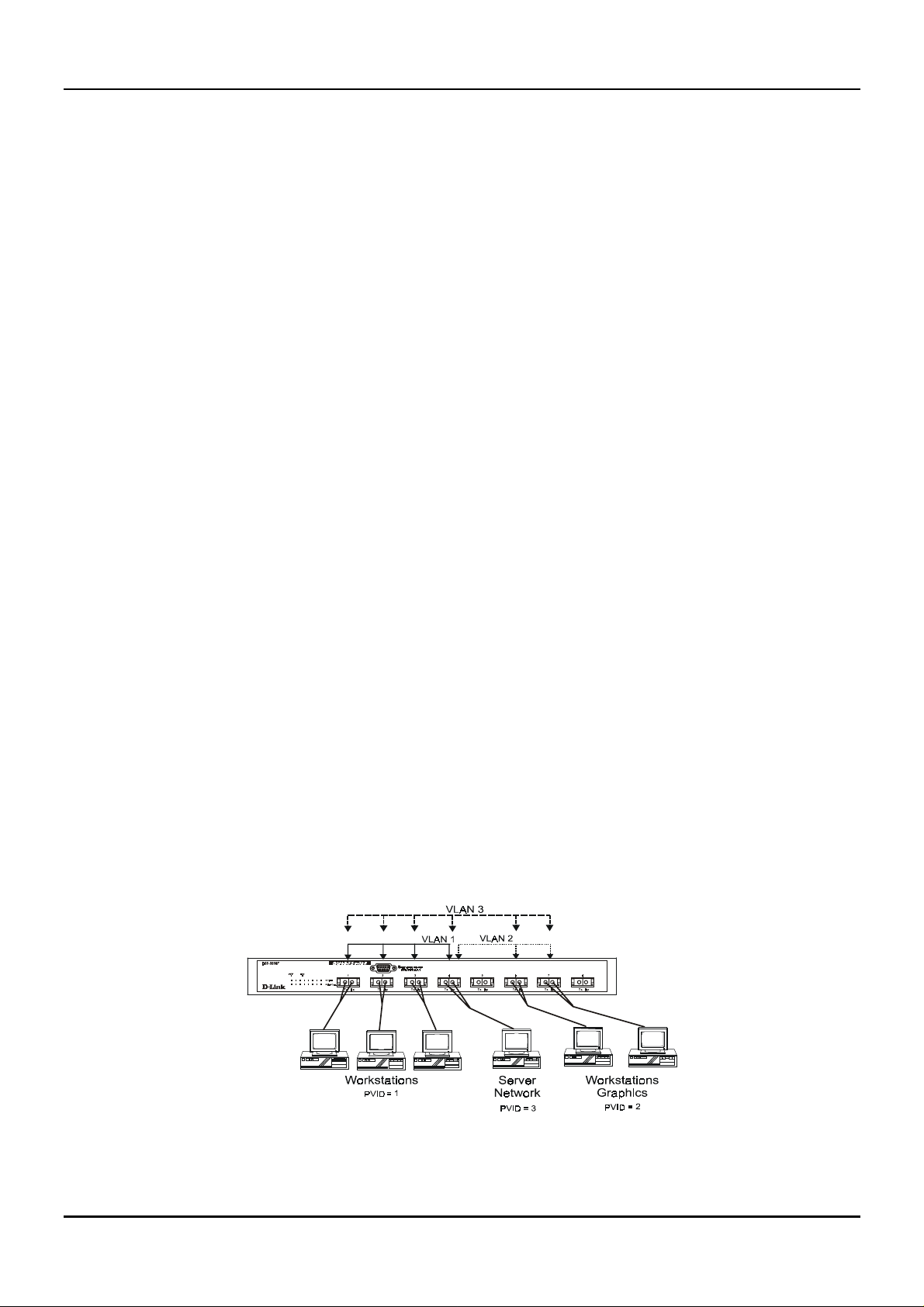
Sharing Resources Across 802.1Q VLANs
Network resources such as printers and servers however, can be shared across 802.1Q VLANs. This is
achieved by setting up overlapping VLANs as shown in the di agram below.
Figure 5-4. Example of typical VLAN configuration
20
Page 28

Gigabit Ethernet Switch User’s Guide
In the above example, there are three different 802.1Q VLANs and each port can transmit packets on o ne of
them according to their Port VLAN ID (PVID). However, a port can receive packets on all VLANs (VID) that it
belongs to. The assignments are as follows:
PVID
(Port VLAN ID)
1Port 1
1Port 2
1Port 3
2Port 6
2Port 7
3Port 4
VID
(VLAN ID)
1 1, 2, 3, 4
2 4, 6, 7
3 1, 2, 3, 4, 6, 7
Ports
Member Ports
Table 5-2. VLAN assignments for Figure 5-4
The server attached to Port 4 is shared by VLAN 1, VLAN 2, and VLAN 3 becau se Port 4 is a member of all
three VLANs (it is listed as a member of VID 1, VID 2, and VID 3). Since it can receive packets from three
VLANs, all ports can succe ssfully send packets to it to be printe d. Ports 1, 2, and 3 send these packets on
VLAN 1 (their PVID=1), and Ports 6 and 7 send these packets on VLAN 2 (PVID=2). The third VLAN
(PVID=3) is used by the server to transmit files that had been requested on VLAN 1 or 2 back to the
computers. All computers that use th e server will receive transmission s from it since they are all located on
ports which are members of VLAN 3 (VID=3).
802.1Q VLANs Spanning Multiple Switches
802.1Q VLANs can span multiple switches as well as yo ur en tire ne two rk. Tw o con side ratio ns to kee p in min d
while building VLANs of this sort are whether the switches are IEEE 802.1Q-compliant and w hether VLAN
packets should be tagged or untagged.
Definitions of relevant terms are as follows:
♦ Tagging
enabled will put the VID n umber, pr iority, and other VLAN informatio n into all p ackets th at flo w out it. If
a packet has previously been tagged, the port w ill no t alte r the packe t, thu s kee pin g the VLAN in fo rmatio n
intact. Tagging is used to send packets from one 802.1Q-compliant device to another.
♦ Untagging
enabled will take all VLAN info rmation ou t of all packe ts that flo w out o f a po rt. If the p acket do esn’t hav e
a VLAN tag, the port will not alter the packet, thus keeping the packet free of VLAN information.
Untagging is used to send packets from an 802.1Q-compliant switch to a non-compliant device.
♦ Ingress port
Ingress Filter enabled, the switch will examine each packet to determine whether or not it is a VLAN
member and then take one of two actions: if the port is not a member of a VLAN, the packet will be
dropped; if the port is a member of a VLAN, then the packet will be forwarded. Othe rwise, if the Ingress
Filter is disabled, then the switch will process any packet received at this port in its normal fashion.
♦ Egress port
an end station, and taggin g decisions mu st be made. If an egress port is connecte d to an 802.1Q- compliant
switch, tagging should be enabled so the other device can take VLAN data into account when making
The act of putting 802.1Q VLAN information into the header of a packet. Ports with tagging
The act of stripping 802.1Q VLAN information out of the packet he ader . Ports with u ntaggin g
A port on a switch where packets are flowing into the switch. If an ingress port has the
A port on a switch where packets are flowing out of the switch, either to another switch or to
21
Page 29
Gigabit Ethernet Switch User’s Guide
forwarding de cisions (this allows VLANs to span multiple switches). If an egress conne ction is to a noncompliant switch or end-station, tags should be stripped so the (now normal Ethernet) packet can be read
by the receiving device.
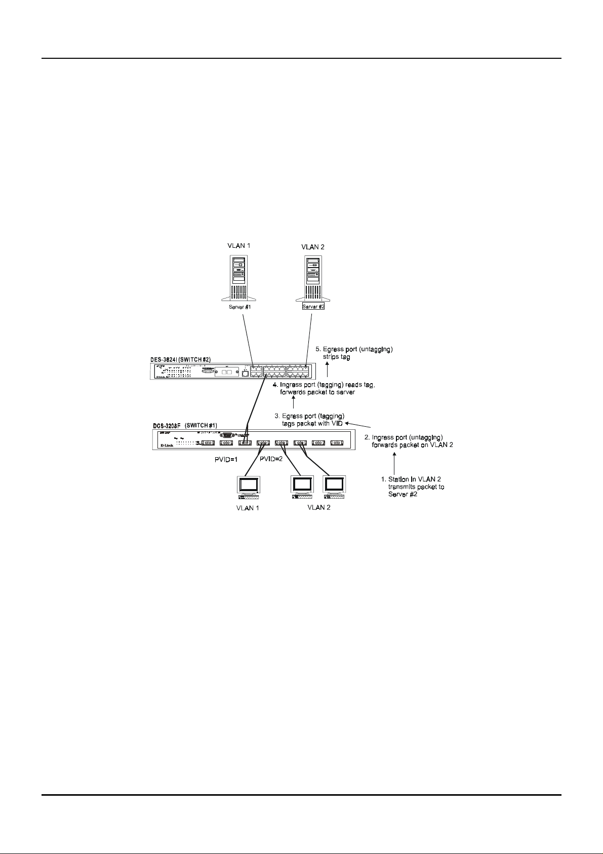
VLANs Over 802.1Q-compliant Switches
When switches maintaining th e same VLAN s are 802.1Q -c o mplian t, it is po ssible to u se tag g ing . Tagg in g p uts
802.1Q VLAN information into each packet header, enabling o the r 802.1Q- com plian t switche s that re ceiv e the
packet to know how to treat it. Upon receiving a tagged packet, an 802.1Q-compliant switch can use the
information in the packet header to maintain the integrity of VLANs, carry out priority forwarding, etc.
Data transmissions between 802.1Q-compliant switches take place as shown below.
12345678
Tx Rx Tx Rx Tx Rx Tx Rx Tx Rx Tx Rx Tx Rx Tx Rx
Figure 5-5. Data transmissions between 802.1Q-compliant Switches
In the above example , step 4 is the key element. Because the packet has 802.1Q VLAN data encoded in its
header, the ingress port can make VLAN-based decisions about its delivery: whether server #2 is attached to a
port that is a member of VLAN 2 and, thus, should the packet be delivered; the queuing priority to give to the
packet, etc. It can also perform these functions for VLAN 1 packets as well, and, in fact, for any tagged packet
it receives regardless of the VLAN number.
If the ingress port in step 4 were connected to a non-802.1Q-compliant device and was thus receiving
untagged packets, it would tag its own PVID onto the packet and use this information to make forwarding
decisions. As a result, the packets coming from the non-compliant device would automatically be placed on the
ingress ports VLAN and could only communicate with other ports that are members of this VLAN.
Port-Based VLANs
Port-based VLANs are a simplified version of the 802.1Q VLANs described in the previous section. In portbased VLANs, all the 802.1Q settings are pre-configured allowing you to quickly and easily setup and
maintain port-based VLANs on your network.
22
Page 30

Gigabit Ethernet Switch User’s Guide
In port-based VLANs, broadcast, multicast and unkn own packets will be limited to within the VLAN. Thus,
port-based VLANs effectively segment your network into broadcast domains. Furthermore, ports can only
belong to a single VLAN.
Because port-based VLANs are uncomplicated and fairly rigid in their implementation, they are best used for
network administrators who wish to quickly and easily setup VLANs in order to isolate limit the effect of
broadcast packets on their network.
For the most secure implementation, make sure that end stations are directly connected to the switch.
Attaching a hub, switch or other repeater to the port causes all stations attached to the repeater to become
members of the port-based VLAN.
To setup port-based VLANs, simply select a VLAN ID number, name the VLAN, and specify which po rts will
be members. All other ports will automatically be forbidden membership, even dynamically as a port can
belong to only one VLAN.
Broadcast Storms
Broadcast storms are a common problem on today’s networks. Basically, they consist of broadcast packets that
flood and/or are looped on a network causing noticeable performance degradation and, in extreme cases,
network failure. Broadcast storms can be caused by network loops, malfunctioning NICs, bad cable
connections, and applications or protocols that generate broadcast traffic, among others.
In effect, broadcast storms can originate from any number of sources, and once they are started, they can be
self-perpetuating, and can even multiply the number of broadcast packets on the network over time. In the
best case, network utilization will be high and bandwidth limited until the hop counts for all broadcast
packets have expired, whereup on the packets will be discarded and the netwo rk will return to no rmal. In the
worst case, they will multiply, eve ntually using up all the ne twork band width (altho ugh ne twork applicatio ns
will usually crash long before this happens), and cause a network meltdown.
Broadcast storms have long been a concern for network administrators with routers traditionally being used
to prevent their occurrence, and if that failed, to at least limit their scope. However, with the advent of
VLANs, switches are now able to limit broadcast domains better and cheaper than routers. Also, many
switches, including the DG S-3208F, have broadcast sensors an d filters built into each port to furth er control
broadcast storms.
Segmenting Broadcast Domains
The Switch allows you to segment broadcast domains. It does this by forwarding packets only to ports in the
same broadcast domain or VLAN. Thus, broadcast packets will only be forwarded to ports that are members of
the same broadcast domain or VLAN. Other parts of the network are effectively shielded. As a result, the
smaller the broadcast domain, the less effect a broadcast storm will have. Since VLANs and broadcast
domains are implemented at each switch port, they can be quite effective in limiting the scope of broadcast
storms.
Eliminating Broadcast Storms
SNMP agents can be programmed to monitor the number of broadcast packets on switch ports and act on the
data. When the number of broadcast packets on a given port rise past an assigned threshold, an action can be
triggered. When enabled, the usual action is to block the port to broadcast frames, which discards all
broadcast frames arriving at the port from the attached segment. Not only does this isolate the broadcast
domain, but it actually starts removing broadcast packets from the affected segment. When the number of
23
Page 31

Gigabit Ethernet Switch User’s Guide
broadcast packets falls to an acceptable level (below a
falling threshold
), the SNMP agent can remove the
blocking condition, returning the port to its normal operational state.
In the Switch, the default rising threshold is met when more than 500 broadcast packets per second are being
detected on a specified port. Once the rising threshold is surpassed for a duration of more than 5 seconds, it
will trigger the broadcast storm rising action configured by the user. The default falling threshold is met if
there are less than 250 broadcast packets per second. It is triggered once the duration is at least 30 seconds.
The actions can easily be defined by using a normal SNMP management program or through the console
interface.
24
Page 32

Gigabit Ethernet Switch User’s Guide
6
6 U
Your Gigabit Ethernet Switch supports a console management interface that allows you to set up and control
your Switch, either with an ordinary terminal (or terminal emulator), or over the network using the TCP/IP
protocol. You can use this facility to perf orm many basic network management fun ctions. In addition,
Telnet
the console program will allow you to set up the Switch for management using an SNMP-based network
management system. This chapter describes how to use the console interface to access the Switch, change its
settings, and monitor its operation.
SING THE
C
ONSOLE INTERFACE
Setting Up A Console
First-time configuration must be carried out through a “console,” that is, either (a) a VT100-type serial data
terminal, or (b) a computer running communications software set to emulate a VT100. The console must be
connected to the Diagnostics port. This is an RS-232 port with a 9-socket D-shell connector and DCE-type
wiring. Make the connection as follows:
Obtain suitable cabling for the connection.
1.
You can use either (a) a “null-modem” RS-232 cable or (b) an ordinary RS-232 cable and a null-modem
adapter. One end of the cable (or cable/adapter combination) must have a 9-pin D-shell connector suitable
for the Diagnostics port; the other end must have a connector suitable for the console’s serial
communications port.
Power down the devices, attach the cable (or cable/adapter combination) to the correct port s, and restore
2.
power.
Set the console to use the following communication parameters for your terminal:
3.
9600 baud
♦
No parity checking (sometimes referred to as “no parity”)
♦
8 data bits (sometimes called a “word length” of 8 bits)
♦
1 stop bit (sometimes referred to as a 1-bit stop interval)
♦
VT-100/ANSI compatible
♦
Arrow keys enabled
♦
A typical console connection is illustrated below:
25
Page 33

Gigabit Ethernet Switch User’s Guide
Figure 6-1. Example of a console connection
Connecting to the Switch Using Telnet
Once you have set an IP address for your Switch, you can use a
terminal mode) to access and control the Switch. Most of the screens are identical, whether accessed from the
console port or from a
next chapter,
“Web-Based Network Management,”
interface. You can also use a Web-based browser to manage the Sw itch. See the
Telnet
for further information.
program (in a VT-100 compatible
Telnet
Console Usage Conventions
The console interface makes use of the following conventions :
Items in
1.
Configuration screen.
Items in
2.
delete keys to erase characters behind and in front of the cursor.
The up and down arrow keys, the left and right arrow keys, the tab key and the backspace key, can be
3.
used to move between selected items. It is recommended that you use the tab key and backspace key for
moving around the console.
Items in UPPERCASE are commands. Moving the selection to a command and pressing <Enter> will
4.
execute that command, e.g. SAVE, EXIT, etc.
<
angle brackets
[square brackets]
>
can be toggled on or off using the space bar, excepting the entries on the Port
can be changed by typing in a new value . You can use the backspace and
First Time Connecting To The Switch
The Switch supports user-based security that can allow you to prevent unauthorized users from accessing the
Switch or changing its settings. This section tells how to log onto the Switch.
Note: The passwords used to access the Switch are case sensitive; therefore, “S” is not the same as
“s.”
When you first conne ct to the Switch, you will be pre sented with the first login scre en (shown below). If the
initial login screen does not appear, press Ctrl+R (hold down the Ctrl key, press and release the R key, and
then release Ctrl) to call up the screen. Ctrl+R can also be used at any time to refresh the screen.
26
Page 34

Gigabit Ethernet Switch User’s Guide
Figure 6-2. Initial Screen, first time connecting to the Switch
Press <Enter> (Note: Leave the Username and Password fields blank). You will see th e main menu shown
below:
Figure 6-3. Main Menu
The first user automatically gets
one
Administrator
-level user for the Switch.
Administrator
privileges (See
Table 6-1
). It is recommended to create at least
Steps to Create Administrator or Normal User Access
From the screen above, move the cursor to
Account Management
Choose
1.
User Accounts
Enter the new username, assign an initial password, and then confirm the new password. Determine
2.
whether the new user should have
between the two options).
Press APPLY to let the user addition take effect.
3.
Create/Modify User Accounts
menu appears.
menu appears.
Administrator
User Accounts Management
from the
User Account Management
or
Normal User
27
privileges. (Use the space bar to toggle
and press <Enter>. The
menu. The
Add/Modify
User
Page 35

Gigabit Ethernet Switch User’s Guide
Press <Esc> to return to the previous screen or Ctrl+T to go to the root screen.
4.
To see a listing of all user accounts and access levels, press <Esc>. Then choose
5.
Accounts
. The
View/Delete User Account
screen appears.
Administrator and Normal User Privileges
View/Delete User
There are two levels of user privileges:
users with
Administrator
privileges may not be available to
menus for the two types of users:
The following table summarizes
Administrator
Menu Administrator Normal User
Configuration Yes Yes, view only.
Network Monitoring Yes Yes, view only.
Community Strings and Trap Stations Yes Yes, view only.
Update Firmware and Configuration
Files
User Account Management
Add/Modify User Account Yes No
View/ Delete User Account Yes No
System Utilities Yes Yes
Factory Reset Yes No
Restart System Yes No
Table 6-1. Administrator and Normal User Privileges
After establishing a User Account with
Save Changes
menu (seen below). Pressing any key will return to the main menu. You are now ready to
operate the Switch.
Administrator
and
Normal User
Administrator
and
Normal User
Normal User
. Some menu selections available to
s. The main menus shown are the
privileges:
Privilege
Yes No
-level privileges, press <Esc> twice. Then choose the
Save Changes
In order to retain any modifications made in the current session, it is necessary to choose
the main menu. The following screen will appear to indicate your new settings have been processed:
28
Save Changes
from
Page 36

Figure 6-4. Save Changes screen
Gigabit Ethernet Switch User’s Guide
Login On The Switch Console By Registered Users
To log in once you have created a registered user,
Type in your Username and press <Enter>.
1.
Type in your Password and press <Enter>.
2.
The main menu screen will be displayed based on your
3.
privilege.
Add/Modify User Account
To add or change your user password:
Choose
1.
Management
User Accounts Management
menu appears:
from the main menu. The following
Administrator
or
Normal User
access level or
User Account
29
Page 37

Gigabit Ethernet Switch User’s Guide
Figure 6-5. User A ccount Management menu
Choose
2.
Create/Modify User Account
. The following screen appears:
Figure 6-6. Add/Modify User A ccounts screen
Type in your Username and press <Enter>.
3.
If you are a new user, type in the Old Password and press <Enter>.
4.
Type in the New Password you have chosen, and press <Enter>. Type in the same new password in the
5.
following field to verify that you have not mistyped it.
Determine whether the new user should have
6.
Choose the APPLY command to let the password change take effect.
7.
This method can also be used by an
Administrator
Normal User
-level user to change another user’s password.
or
Administrator
privileges.
30
Page 38

View/Delete User Account
Gigabit Ethernet Switch User’s Guide
Access to the console, whether using the console port or via
password. Up to three user names can be de fined. The console interface will not let yo u delete the current
logged-in user, however, in order to prevent accidentally deleting all of the users with
Only users with the
To view your user password:
Choose
appears:
View/Delete User Accounts
Administrator
privilege can delete users.
from the
User Account Management
, is controlled using a user name and
Telnet
Administrator
menu. The following screen
privilege.
Figure 6-7. View/Delete User A ccount scr een
To delete your user password:
Toggle the Delete field of the user you wish to remove to
1.
Press APPLY to let the user deletion take effect.
2.
Yes
.
Setting Up The Switch
This section will help prepare the Switch user by describing the
Configuration Update, System Utilities,
menus.
System Configuration
Choose
appears:
System Configuration
to access the first item on the DGS-3208F main me nu. The following menu
and
SNMP Configuration
System Configuration, Firmware and
menus and their respective sub-
31
Page 39

Gigabit Ethernet Switch User’s Guide
Figure 6-8. System Configuration menu
You will need to change some settings to be able to manage the Switch from an SNMP-based network
management system such as SNMP v1 or to be able to access the Switch using the
chapter for Web-based management information.
protocol. See the next
Telnet
Configure IP Address
The Switch needs to have a TCP/IP address assigned to it so that the network management system or
client can find it on the network. The
different interfaces used on the Switch: the Ethernet interface used for in-band communication, and the SLIP
interface used over the console port for out-of-band communication.
Choose
screen appears:
Configure IP Address
IP Configuration
to access the first ite m on the
screen allows yo u to chan ge th e settin gs fo r the two
System Configuration
menu. The following
Telnet
Figure 6-9. IP Configuration screen
Each of the fields on this screen takes effect the next time the system is restarted. Fields that can be set
include:
32
Page 40

Gigabit Ethernet Switch User’s Guide
♦ Assign IP
BOOTP
Mask and Default Gateway settings defined in this screen upon being rebooted. If
Switch will send out a BOOTP broadcast request when it is powere d up. The BOOTP proto col allows IP
addresses, network masks, and default gateways to be assigned by a central BOOTP server. If this
option is set, the Switch w ill first look for a BOOTP server to provide it with this information bef ore
using the supplied settings. If
sent when the Switch is powered up.
♦ IP Address
communications. Should be of the form
decimal) between 0 and 255. This add ress should be a u nique address o n a network assign ed to you by
the central Internet authorities. The same IP address is shared by both the SLIP and Ethernet network
interfaces.
♦ Subnet Mask
form
subnetting is being done, the value should be 255.0.0.0 for a Class A network, 255.255.0.0 fo r a Class B
network, and 255.255.255.0 for a Class C network.
♦ Default Gateway
subnet should be sen t. This is usually the address o f a router o r a ho st acting as an IP gatewa y. If your
network is not part of an internetwork, or you do not want the Switch to be accessible outside your local
network, you can leave this field blank.
Determines whether the Switch should get its IP Address settings from the user (
server, or a
Determines the IP address used by the Switch for receiving SNMP and
Bitmask that determines the extent of the subnet that the Switch is on. Should be of the
xxx.xxx.xxx.xxx
DHCP
, where each
IP address that determines where frames with a destination outside the current
server. If
DHCP
is chosen, a Dynamic Host Configuration Protoco l request will be
is a number (represented in decimal) between 0 and 255. If no
xxx
Manual
is chosen, the Switch will use the IP Address, Subnet
xxx.xxx.xxx.xxx
, where each
is a number (represented in
xxx
BOOTP
Manual
is chosen, the
), a
Telnet
Configure Console
You can use the
console management or for out-of-band TCP/IP communications using SLIP, and to set the bit rate used for
SLIP communications.
Choose
screen appears:
Configure Console
Console Options
to access the last item on the
screen to choose whether to use the Switch’s RS-232C serial port for
System Configuration
menu. The following
Figure 6-10. Console Configuration screen
The following fields under Settings on Restart can be set:
♦ Console Timeout
.
Never
This setting for the restart of the console is
33
15 mins, 30 mins, 45 mins, 60 mins
, or
Page 41

Gigabit Ethernet Switch User’s Guide
♦ Serial Port
for console management, starting from the next time the Switch is restarted. In this field, you can
toggle between
♦ Baud Rate
Applies only when the serial port is being used for out-of-band (SLIP) management; it does not apply
when the port is used for the console port. Available speeds are
second. The default setting in this Switch version is
Determines whether the serial port should be used for out-of-band (SLIP) management or
or
SLIP
Determines the serial port bit rate that will be used the n ext time the Switch is restarted.
Console
port type settings.
9600
2400, 9600, 19200
.
and
38400
bits per
Configure Switch
The
Switch Configuration
set the
Switch using SNMP reques ts, allowing the settings to be used for network management purposes.
Choose
screen appears:
System Name, System Location
Configure Switch
screen shows various pieces of information about your Switch, and allows you to
, and
System Contact
to access the second item on the
. These settings can be retriev ed from the
System Configuration
menu. The following
Figure 6-11. Switch Configuration screen
The fields you can set are:
♦ System Name
name to the Switch for administrative purposes. The Sw itch’s f ully qualif ied do main n ame is o fte n u sed ,
provided a name has been assigned.
♦ System Location
indicate the physical location of the Switch for administrative purposes.
♦ System Contact
name and contact information for the person responsible for administering the Switch.
The
Configure Advanced Switch Features
prevention. Press ADVANCE SETTINGS on the
Advanced Switch Features
Corresponds to the SNMP MIB II variable
Corresponds to the SNMP MIB II variable
Corresponds to the SNMP MIB II variable
screen allows you to enable or disable head of line blocking
System Configuration
screen:
34
system.sysName
, and is used to give a
system.sysLocation
sysContact
, and is used to give the
window to access the
, and is used to
Configure
Page 42

The field you can set is:
Gigabit Ethernet Switch User’s Guide
Figure 6-12. Configure Advanced Switch Features screen
♦ Head Of Line (HOL) Blocking Prevention
a packet to a “blocking” port, that is, a port where an excess of packets are queued up. Note that when a
multicast packet or a packet with an unknown destination address needs to be forwarded to several port s,
and if some of them are “blocking”, the packet will not be discarded, rather it will be forwarded only to the
ports that are not “blocking.”
If
Enabled
, this function is des igned to prevent forwarding
Configure Ports
The
Port Configuration
partition a port, or for observation, device repair, or security reasons. Great caution, however, must be
observed when p artitioning a port; you should make sure that the partitioned port is not being used as the
port to control or monitor the condition of other devices.
To change the configuration of a port:
Select
1.
screen appears:
System Configuration
screen allows you to change the port state in the case when you would like to
from the main menu and then choose
Configure Ports
. The following
35
Page 43

Gigabit Ethernet Switch User’s Guide
Figure 6-13. Port Configuration screen
Specify the port range and specific port in the Configure Ports and Port fields, respectively.
2.
In the State field, change the port state to
3.
In the Speed/Duplex field,
4.
In the Flow Ctrl field, t oggle
5.
In the Priority field, select
6.
Set Port lock to
7.
In the Broadcast Storm Rising Action and Broadcast Storm Falling Action fields, set the desired
8.
Enabled
1000M/Full
or On.
Off
High, Low
or
Disabled
Enabled
will always be displayed.
, or
Normal
.
or
.
Disabled
.
settings, including the Thresholds. See below for further explanation.
Press APPLY and hit <Enter>.
9.
The fields you can set are:
♦ Configure Ports & Port
♦ State
When you disable the state, the port will be p artitioned from the rest of the network. In this
Select the desired port range and the specific port in these fields.
partitioned state, it will only be able to accept management packets. All other packets will be dropped.
♦ Speed/Duplex
When this function is enable d, if too many co nsecutive collision s occur on an individ ual
port, the port will be blocked off u ntil a good packet is seen on the wire. If a port is p artitioned, the
Switch can only transmit data, not receive it.
♦ Flow Ctrl
Enables or disables IEEE 802.3x flow control on the port. Flow control allows the port to
send a Pause packet to a transmitting IEEE 802.3x-compliant device, so that its buffers don’t overflow
and data is not lost.
setting will also be set to
♦ Priority
Sets the priority f or traffic arriving at this po rt to
Toggles flow control On or Off
Auto.
, unless Speed/Duplex is set to
High, Normal
, in which case this
Auto
or
. Higher priority
Low
packets are processed first in the Switch’s packet queue.
♦ Port Lock
When enabled, stops automatic learning for all stations connected to the port. Entries in the
Forwarding Table for all devices connected to the port will age out. The only traffic this port will allow is
traffic from machines whose MAC addresses are manually ent ered in the Static Forwardi ng Table.
36
Page 44

Gigabit Ethernet Switch User’s Guide
♦ Broadcast Storm
increases steadily. The Broadcast Storm controls make it possible to (1) prevent a broadcast storm from
spreading from one port to others, and (2) restore normal forwarding of broadcast packets when the
storm has abated.
The Rising Action control and its associated Threshold control specify what action (if any) the Switch
should take when broadcast traffic received on the port increases to or exceeds the equivalent of a
specified number o f bro ad cast packe ts pe r se co nd . The thre sh old can be se t to 1 to 1,488,000 p acke ts pe r
second (the def ault is 500) ; the risin g actio n can be se t to
discard all broadcast packets received on the port), or
received on the port and send a trap to the trap manager[s]).
The Falling Action control and its associated Threshold control spe cify what action (if any) the Switch
should take when broadcast traffic received on the port, after reaching or exceeding the “rising action”
threshold, decreases to or falls below the equivalent of a specified number of broadcast packets per
second. The thresho ld can be set to 1 to 1,488,000 packets per second (the d efault is 250); the falling
action can be set to
packets received on the port), or
the port and send a trap to the trap manager[s]).
Press CTRL+S to let the chan ges take effect. If you w ish these changes to be the d efault for the Switch,
return to the main menu and choose
STP Port State (whether the Spanning Tree Protocol is enabled or disabled on this port) and Status reflect the
current conditions of the port. They are read-only fields and cannot be changed.
As a broadcast storm develops, the number of broadcast packets received on a port
Do Nothing
(this is the default),
Forward & Trap
Save Changes
(discontinue blocking of broadcast packets received on
.
Do Nothing
Block & Trap
Forward
(this is the default),
(discard all broadcast packets
(that is, discontinue blocking of broadcast
Block
(that is,
Configure Port Mirroring
The
Port Mirroring Configuration
and redirect the copies to another port. You can attach a monitoring device to the mirrored port, such as a
sniffer or an RMON probe, to view details about the packets passing through the first port. This is useful for
network monitoring and troubleshooting purposes.
Choose
Configuration
Configure Port Mirroring
screen:
screen allows you to copy frames transmitted and received on a port
on the
System Configuration
menu to access the
Port Mirroring
Figure 6-14. Port Mirroring Configuration screen
To configure a mirror port, select the port from where you want to copy frames in the Source Port field. Then
select the port which receives the copies from the source port in the Target Port field. The target port is where
37
Page 45

Gigabit Ethernet Switch User’s Guide
you will connect a monitoring/troubleshooting device such as a sniffer or an RMON probe. When you are
finished, change the Status to
Enabled
and then press APPLY to let your changes take effect.
Configure Spanning Tree Protocol
The Spanning Tree Algorithm Parameters can be used for creating alternative paths in your network. The
Protocol Parameters allow you to change the behind the scene parameters of the Spanning Tree Algorithm at
the bridge level. The parameters for this section have been fully explained in Chapter 5’s “
Management Concepts.
recommende d that you read these section s, as well as the introductory sectio n in the same chapter entitled
Spanning Tree Algorithm
To change the Protocol Parameters:
” See
STA Operation Levels: On the Bridge level
before changing any of the parameters.
, and
User-Changeable Parameters
Switch
. It is
Choose
1.
Configure Spanning Tree Protocol
Choose
2.
Configure Spanning Tree Protocol
Figure 6-15. Configure Spanning Tree Protocol menu
STP Parameter Settings
from the
menu will be displayed:
to access the following screen:
System Configuration
menu. The following
Figure 6-16. STP Parameters Setting screen
38
Page 46

Gigabit Ethernet Switch User’s Guide
Change the
3.
Enter the Bridge Max Age in the Max Age(6-40 sec) field.
4.
Enter the Bridge Hello Time in the Hello Time(1-10 sec) field.
5.
Enter the Bridge Forward Delay time in the Forward Delay(4-30 sec) field.
6.
Enter the Bridge Priority in the Bridge Priority(0-65535) field.
7.
Press APPLY to let your changes take effect.
8.
Disabled
setting to
Enabled
in the Spanning Tree Protocol field.
The information on the screen is described as follows:
♦ Spanning Tree Protocol
Select
Enabled
♦ Time Since Topology Changes(sec)
to implement the Spanni ng Tree Protocol.
Read-only object displays the last time changes were made to
the network topology. These chan ges usually occur when backup paths are activated due to prim ary
path failures.
♦ Topology Change Count
Read-only object displays the number of times (since the current
management session with the device was started) changes were made to the network topology.
Changes usually occur on the network when backup paths are activated.
♦ Designated Root
Read-only object displays the MAC (Ethernet) address of the bridge/switch on the
network that has been chosen as the STP root.
♦ Root Cost
Read-only object displays the cost for the path between the switch and the root brid ge. If
the switch is the root bridge, then the root cost is zero.
♦ Root Port
Read-only object identifies the port (on the bridge) that offers the least path cost from the
bridge to the root bridge. In the event of a network loop, data packets will pass through the root port.
♦ Max Age(Sec)
Read-only object indicates the maximum age of STP information learned from the
network (on any port) before it is discarded.
♦ Forward Delay(sec)
Read-only object indicates how fast any port on the bridge can change its
spanning state when moving towards the forwarding state. The value determines how long t h e port
stays in each of the listening and learning states, which precede the forwarding state.
♦ Hold Time(Sec)
Read-only object displays the time interval during which no more than two configuration
BPDUs shall be transmitted by the bridge.
♦ Root Priority
Read-only object displays the priority number of the root bridge of th e Spanning Tree.
The value is used in conjunction with the bridge MAC address to set the bridge ID, which in turn is
used when determining the root bridge of a multibridged network. The root bridge is responsible for
processing data packets when network loops occur. The smaller the number set, the higher the bridge
priority is. The higher the bridge priority, the more chance the bridge has of becoming the root bridge.
A bridge priority ranges from 0 to 65535, with 0 being the highest priority.
♦ Max Age(6-40 Sec)
Maximum Age is a read-write object that can be set from 6 to 40 seconds. At the
end of the Maximum Age, if a BPDU has still not been received from the Root ridge, your Switch will
start sending its own BPDU to all other switches for permission to become the Root Bridge. If it turns
out that your Switch has the lowest Bridge Identifier, it will become the Root Bridge.
♦ Hello Time(1-10 Sec)
Hello Time is a read-write object that can be set from 1 to 10 seconds. This is
the interval between two transmissions of BPDU packets sent by the Root Bridge to tell all other
switches that it is indeed the Root Bridge. If you set a Hello Time for your Switch, and it is not the
Root Bridge, the set Hello Time will be used if and when your Switch becomes the Root Bridge.
39
Page 47

Gigabit Ethernet Switch User’s Guide
♦ Forward Delay(4-30 Sec)
seconds. This is the time any port on the Switch spends in the listening state while moving from the
blocking state to the forwarding state.
♦ Bridge Priority(0-65535 Sec)
65535. This is the priority number of the bridge. The value is used in conjunction with the bridge
MAC address to set the bridge ID, which in turn is used when determining the root bridge of a
multibridged network. The root bridge is responsible for processing data packets when network loops
occur. The smaller the number set , the higher the bridge priority is . The higher the bridge priority,
the more chance the bridge has of becomi ng the root bridge. Zero is the highest priority.
To change the parameters on individual ports:
Choose
1.
Choose
2.
appears:
Configure Spanning Tree Protocol
STP Port Control
The Forward Delay is a read-write object that can be set from 4 to 30
A Bridge Priority is a read-write object that can be set from 0 to
from the
from the
Configure Spanning Tree Protocol
System Configuration
menu.
menu. The following screen
Figure 6-17. Spanning Tree Protocol Custom Settings screen
Change the
3.
Set the path cost for the port between 1 and 65535 in the Cost field.
4.
Set the priority for the port between 0 and 255 in the Priority field.
5.
Press APPLY and hit <Enter>.
6.
Disabled
setting of the STP Status field to
Enabled
.
Configure Filtering and Forwarding Table
When a packet hits the Switch, the Switch looks in the filtering and forwarding tables to decide what to do
with the packet; either to filter it off the network, or to forward it through the port on which its destination
lies. The
well as to select an age-out time of the MAC address in the selected address table. This screen also provides
access to three additional configuration screens related to the Switch’s filtering and forwarding tables.
Choose
following screen:
Configure Filtering and Forwarding Table
Configure Filtering and Forwarding Table
screen allows you to stop or start address learning as
from the
System Configuration
menu to access th e
40
Page 48

Figure 6-18. Configure Filtering and Forwarding Table screen
The following fields at the top of the screen can be set:
Gigabit Ethernet Switch User’s Guide
♦ Lock Address Table (Stops Auto -Learning)
This function is used mostly for security purposes. When
the forwarding table is lo cked, the Switch will no longer le arn the MAC addresses for new hosts. If your
network configuration doesn’t change, locking the forwarding table helps keep intruders off your network,
since any packet coming from an unknown source address will be dropped by the Switch.
♦ Address Table Lookup Mode
Choices are
Level 0, Level 1, Level 2, Level 3, Level 4, Level 5, Level, 6
This setting allows the user to tailor the MAC address look up procedure.
, and
Level 7
. The higher the level, the
more MAC addresses can be learned by the Switch. However, a side effect is that throughput will be
degraded the higher the level you select. This setting will take effect after your system reboots.
♦ MAC Address Age-out Time
Enter the desired MAC addr ess age-out time in this field (10 to 1000000
seconds) .
Configure Static Forwarding Table
The
Static Forwarding Table
To access the
from the
bottom of the
Static Forwarding Table
System Configuration
Configure Filtering and Forwarding Table
screen displays a list of manually defined static MAC address entries.
screen, choose
menu. Then select
Configure Filtering and Forwarding Table
Configure Static Forwarding Table
from the
screen. The following screen appear s:
41
Page 49

Gigabit Ethernet Switch User’s Guide
Figure 6-19. Static Forwarding Table screen
By mapping a port to a destination MAC address, the Switch can permanently forward traffic to the specified
device, even after long periods of network inactivity or during times of network congestion.
To make a change to the
Static Forwarding Table
screen, choose either
Add
or
Remove
in the Action
field. Then enter the MAC Address, the Port number that permanently forwards traffic from the specified
device, regardless of the device’s network activity or current network congestion, enter a VLAN (if
applicable), and press APPLY.
The following fields at the top of the screen can be set:
♦ Action
Choose
♦ MAC Address
Add
or
Remove
for each entry from the table.
Enter a MAC address in this field at the top of the screen. This is the MAC address of
the device that you are creating a permanent forwarding address for. A total of ten destination
addresses per page will be seen at the bottom of the screen. The Switch can hold up to 256 entries.
♦ Port
The port number is entered in this field at the top of the scre en. The Switch will alway s forward
traffic to the specified device through this port. The bo ttom of the screen will display a correspo nding
destination address.
♦ VLAN
Enter the desired VLAN ID number.
In the lower part of the screen, Destination MAC Address, Destination Port, VLAN, and Status are all
read-only fields. The status of the static forwarding table entry can be “in use” or “not apply.” “Not apply”
means that there is a static filter for the same MAC address. Static filters always take precedence over
static forwarding entries. The Sw itch w ill auto matically u pg rad e the Status to “in u se” o nce the static f ilter
is removed.
Configure MAC Address Filtering
The
Static Filtering Table
network) management specifying the set of ports to which packets received from specific ports and containing
specific destination addresses are not allowed to be forwarded. You can use the
screen for network security purposes thereby discarding unwanted addresses from the Forwarding Table.
Dynamic Filtering and Static Filtering are among the two important features of the Static Filtering Table.
They are defined here briefly as follows.
Learning Process as a result of observation of network traffic in the Filtering Database.
screen contains filtering information configured into the Switch by (local or
Static Filtering Table
Dynamic Filtering
is when a dynamic entry is created by the
Static Filtering
is
42
Page 50

Gigabit Ethernet Switch User’s Guide
defined as static entries that may be added and remove d from the Filtering Database by th e user. They are
not automatically removed by any timeout mechanism.
To access the
the
System Configuration
the
Configure Filtering and Forwarding Table
Static Filtering Table
menu. Then select
screen, select
Configure MAC Address Filtering
Configure Filtering and Forwarding Table
screen. The following screen appear s:
Figure 6-20. Static Filtering Table screen
To make a change to the
Static Filtering Table
screen, choose
Add
or
the MAC Address and VLAN ID number (if applicable) and press APPLY.
Remove
from
from the bottom of
in the Action field. Then enter
Configure Static Multicast Forwarding
The
Static Multicast Forwarding Table
multicast group. To access this scre en , se lect
Filtering and Forwarding Table
Figure 6-21. Static Multicast Forwarding Table screen (version one)
screen. The following screen will appear:
screen allows you to forward traffic over each port for one
Configure Static Multicast Forwarding
from the
Configure
To make a change to the
Static Multicast Forwarding Table
screen above, choose
Add
or
Remove
in the
Action field. Then enter the MAC Address and VLAN. Next place a V over the dash “–“ in the Port field to
43
Page 51

Gigabit Ethernet Switch User’s Guide
assign outgoing ports. You may also use this scre en to allow d ynamic up dates via IGMP sn ooping by toggling
the last field t o
Enabled
. Press APPLY to put the changes into effect.
Configure IGMP Filtering
Internet Group Management Protocol (IGMP) allows multicasting on your network. When IP Multicast
Filtering is enabled, the Switch can inte lligently forward (rather that broadcast) IGMP qu eries and reports
sent between devices connected to the Switch and an IGMP-enabled device hosting IGMP on your network.
When enabled for IGMP snooping, the Switch can open or close a port to a specific Multicast group member
based on IGMP messages sent from the device to the IGMP host or vice versa.
To access the
Configuration
The item in this screen is defined as follows:
♦ IP Multicast Filtering (IGMP Snooping)
forward IGMP and Multicast packets instead of broadcasting (flooding) them on all ports. This setting
also enables IGMP Snooping, which enables the switch to read IGMP packets being forwarded through
the switch in order to obtain forward ing information from them (learn which ports co ntain Multicast
members).
IGMP Configuration
menu. The following
screen, select
IGMP Configuration
Figure 6-22. IGMP Configuration screen
This enables or disables the Switch to intelligently
Configure IGMP Filtering
screen will appear:
from the
System
Configure 802.1Q IGMP
If the Switch is in IEEE 802.1Q VLANs mode, the
section in the lower part of the screen. Select Configure 802.1Q IGMP to access the following
IGMP Configuration
menu:
IGMP Configuration
44
screen will offer a VLAN Settin gs
IEEE 802.1Q
Page 52

Figure 6-23. IEEE 802.1Q IGMP Configuration menu
Gigabit Ethernet Switch User’s Guide
Choose
Add/Remove IGMP Control Table
from the screen above to define up to 12 VLANs on the Switch
which can send and receive IGMP packets:
Figure 6-24. Add/Remove IGMP Entry screen
The above screen is used to specify an agent to interface between IGMP and VLAN. The agents are assigned
to a VLAN and allow IGMP query and report packets to be present o n the given VLAN. Only 12 age nts can
exist on the switch at any one time.
Items in the above screen are described below:
♦ Action
♦ VID
Adds or removes an entry (agent) from th e table.
The VLAN number that you wish to create an agent for.
Press APPLY to add the agent to the table.
Go back to the
IEEE 802.1Q IGMP Configuration
menu and choose
Configure IGMP Control Table
order to activate or de activate th e agents an d conf igure se ttings fo r them. Th e follow ing
Configuration
screen appears:
45
in
IEEE 802.1Q IGMP
Page 53

Gigabit Ethernet Switch User’s Guide
Figure 6-25. IEEE 802.1Q IGMP Configuration screen
This allows you to enable or disable these agents and set aging timers for them.
Items in the above screen ar e defined as follows:
♦ VLAN ID
This is the VID number for the VLAN that has an agent attached to it which enables IGMP
packets to be sent and received.
♦ Age-out Timer
If no IGMP query packet has arrived at the Switch before this timer has expired, the
Switch will become the IGMP host for this VLAN.
♦ IGMP Status
Activates or deactivates the agent on this VLAN.
Configure Port-based IGMP
If the Switch is in Port-based mo de, the
the lower part of the screen. Select
Configuration
screen:
IGMP Configuration
Configure Port-based IGMP
screen will offer a VLAN Se ttings section in
to access the follo wing
Port-based IGMP
Figure 6-26. Port-based IGMP Configuration screen
46
Page 54

Gigabit Ethernet Switch User’s Guide
After you have set the age-out timer and either enabled or disabled IGMP status for th e desired VLAN, press
APPLY to let the changes take effect.
Configure VLAN
The
VLAN Configuration
the Switch in
selection by choo sing
each time the mode is changed, t h e Switch must be rebooted before the new mode is activated.
If you have selected
Broadcast Domains
Configuration
IEEE 802.1Q VLANs, Port-based,
MAC-based Broadcast Domains
!
Configure VLANs
menu displays the status of the current VLAN mode and allows a user to restart
or
MAC-based Broadcast Domains
. Please note that the Switch can only support one mode at any given time. Also,
None
and then rebooted the Switch,
will appear at the bottom of the
):
VLAN Configuration
mode, or not to use a
Configure MAC-based
screen (
System
Figure 6-27. VLAN Configuration screen
The information on the top of the screen is described as follows:
♦ Current VLAN Mode
♦ Restart VLAN Mode
802.1Q VLANs, Port-based, or None
chosen.
Displays what mode, if any, is currently enabled on the Switch.
Choose from four settings for this mode:
. After being restarted, the Switch will implement the setting you have
MAC-based Broadcast Domains, IEEE
Configure MAC-based Broadcast Domains
To create MAC-based broadcast domains, simply create the broadcast domain itself in the
MAC-based Broadcast Domains
Add/Remove MAC-based Broadcast Domain Members
broadcast domain will be implemented.
Please note that if the mode is set to
supported in the
Filtering and Forwarding Table
Choose
above to access the
Configure MAC-based Broadcast Domains
Port Configuration
MAC-Based Broadcast Domains Configuration
screen, and then enter MAC addresses to the broadcast doma in in the
screen. Afterwards, restart the Switch and the
MAC-based Broadcast Domains
screen and the Lock Address T able function located on the
screen is not available.
from the bottom of the
, then the Port Lock function is not
VLAN Configuration
menu:
Add/Remove
Configure
screen
47
Page 55

Gigabit Ethernet Switch User’s Guide
Figure 6-28. MAC-based Broadcast Domains Configuration menu
Choose
Add/Remove MAC-based Broadcast Domains
Figure 6-29. Add/Remove MAC-based Broadcast Domains screen
The fields you can set are:
♦ Action
Select the desired action by toggling between
to access the following screen:
Add
and
Remove
.
♦ Domain Name
Enter the name of the broadcast domain.
Press APPLY to add or remove the designated MAC-based broadcast domain.
Broadcast Domains and Numb er of Members reflect the current status. They are read-only fields and cannot
be changed.
Choose
Add/Remove MAC-based Broadcast Domain Members
Domains Configuration
menu to access the following screen:
from the
MAC-Based Broadcast
48
Page 56

Gigabit Ethernet Switch User’s Guide
Figure 6-30. First Add/Remove MAC-based Broadcast Domain Members screen
To configure a broadcast domai n , highlight the desired entry on the screen above and press <Enter>. The
following
Add/Remove MAC-based Broadcast Domain Members
screen appears:
Figure 6-31. Second Add/Remove MAC-based Broadcast Domain Members screen
The fields you can set are:
♦ Action
♦ MAC Address
Select the desired action by toggling between
The MAC address of the broadca st domain member being added or removed.
Please note that the Status field for the M AC address you have entered may read
Add
and
Remove
.
Not-Apply
. Once the Switch
is restarted in MAC-based broadcast domain mode, the MAC-addresses will be applied, meaning that the
broadcast domain is active.
Current Broadcast Domain, Number of members, MAC Address (in the lower part of the screen), and Status
reflect the current conditions. They are read-only fields and cannot be changed.
49
Page 57

Gigabit Ethernet Switch User’s Guide
Configure Port-based VLANs
Choose
Configure Port-based VLANs
Configure VLANs & MAC-based Broadcast Domains
on the
VLAN Configuration
) to access the
screen (
System Configuration
!
Port-based VLAN Configuration
menu pictured below (note that if you have just changed to this mode, you must also reboot the Switch before
being able to work with port-based VLANs):
Figure 6-32. Configure VLAN (Port-Based) menu
The field you can set is:
♦ Management Vid
Select
Add a Port-Based VLAN
Enter a VLAN name for use with in-band mana gement.
from the menu above to access the following screen:
Figure 6-33. Create a Port-based VLAN screen
To create a port-based VLAN, fill in the VLAN N ame field in the screen abov e. Next togg le
port member. Press APPLY to let the changes take effect.
50
or No for each
Yes
Page 58

Gigabit Ethernet Switch User’s Guide
To edit or delete a port-based VLAN, select
(Port-Based)
screen. The following screen appear s:
Figure 6-34. first Edit/Delete a Port-based VLA N screen
Select
Edit
or
in the Action field and then select a VLAN from the column on the right side of the
Delete
screen above. The following screen appears:
Edit/Delete a Port-Based VLAN
from the
Configure VLAN
Figure 6-35. second Edit/Delete a Port-based VLAN screen
Toggle between
or No to assign a port to be a member of the selected VLAN. Press APPLY to let the
Yes
changes take effect.
Configure 802.1Q VLAN
To configure an IEEE 802.1Q VLAN, you must do three things:
Decide if you want to enable Ingress Filtering and enable it on the chosen ports. Ingress filtering applied
1.
on a port causes the port to examine all incoming packets and check whether the port itself is a member of
the VLAN. This is normally used to keep untagged frames off the Switch, although it can have other uses
as well. This setting is configurable for each port in the
51
Ingress Filtering
screen.
Page 59

Gigabit Ethernet Switch User’s Guide
Define which ports will be activ e members of the VLAN. A port can transmit packets onto only one VLAN.
2.
It can receive packets (be a passive member) on many VLANs. Active VLANs are designations defined by
assigning Port VLAN ID numbers (PVIDs) in the
Define the VLAN itself and which po rts will be members (able to receive p ackets from a port th at has this
3.
Port VLAN assignment
screen.
PVID number). At this point, you need to designate whethe r a membe r p ort w ill be a Tag gin g o r U ntag gin g
member port. Defining the ports that w ill be members of a VLAN, and whether they will Tag or U ntag
packets is done in the
802.1Q Static VLAN Settings
screen.
Choose
Configure 802.1Q VLAN
Configure VLAN
) to access the
on the
VLAN Configuration
screen (
IEEE 802.1Q VLANs Configuration
System Configuration
!
menu pictured below (note that if you
have just changed to this mode, you must also reboot the Switch before being able to work with IEEE 802.1Q
VLANs):
Figure 6-36. IEEE 802.1Q VLANs Configuration screen
Choose
Configure Port Ingress Filtering
to access the first item on the menu. The following screen
appears:
Figure 6-37. Ingress Filtering screen
This screen allows you t o set Ingress filtering for each port to either
arrives at the port and Ingress filtering is
Enabled
, the port will check the VLAN ID number of the packet,
Enabled
or
Disabled
. When a packet
52
Page 60

Gigabit Ethernet Switch User’s Guide
and its own VIDs. If there is a match, the port will receive the packet. If the packet doesn’t have a VLAN tag
or the port is not a member of the VLAN for which the packet is tagged, the packet will be discarded.
Note:
If a port is a member of a trunk group but is not the anchor, the items shown in the above tab le
will be read-only and the values will be the same as those for the anchor port.
Choose
Configure Port VLAN ID
menu. The following screen appears:
Figure 6-38. Port VLAN assignment screen
to access the second item on the
IEEE 802.1Q VLAN Configuration
This screen allows you to set a default port VLAN ID number (PVID) for each port. Press APPLY to let the
changes take effect.
Note:
If a port is a member of a trunk group but is not the anchor, the items shown in the above tab le
will be read-only and the values will be the same as those for the anchor port.
Choose
Configure Static VLAN Entry
Configuration
menu. The following screen appears:
to access the third item on the
IEEE 802.1Q VLANs
Figure 6-39. 802.1Q Static VLAN Settings screen
53
Page 61

Gigabit Ethernet Switch User’s Guide
The fields above include:
♦ VID
Enter a VLAN ID from 1 to 4094 and hit <Enter>. This is the VLAN that will be defined on this
screen.
♦ VLAN Name
♦ Tag/Untag
♦ Egress/Forbidden
Description of the VLAN.
Toggle between T for tag and U for untag for each port.
Position the cursor over the dash “–“ representing the appropriate port number and
press <space bar> to sele ct E for Egress membership, or leave the dash “– “. An E designates the specified
port as a static member of the VLAN. A dash means the port is not given VLAN membership for the VID
entered above.
♦ State
♦ Status
Choose
Toggle between
This indicates the current 802.1Q Static VLAN status.
Configure Port GVRP Settings
Configuration
menu. The following screen appears:
Active
and
Inactive
.
to access the fourth item on the
IEEE 802.1Q VLANs
Figure 6-40. GVRP Configuration screen
This screen allows you to enable or disable GARP VLAN Registration Protocol (GVRP), where GARP is the
Generic Attribute Registration Protocol, on individual ports . GVRP updates dynamic VLAN registration
entries and communicates the new VLAN information across the network. This allows, among other things,
for stations to physically move to other switch ports and keep their same VLAN settings, without having to
reconfigure VLAN settings on the Switch. Press APPLY to let your changes take effect.
Configure GMRP
Group Multicast Registration Protocol (GMRP) allows multicasts to be sent on a single VLAN without
affecting other VLANs or broadcast domains. Group registration entries indicate for each port whether frames
to be sent to a group MAC address and on a certain VLAN should be filtered or discarded. Use the
Configuration
To make GMRP configuration changes, select
menu (when
screen to enable or disab le GMRP.
IEEE 802.1Q VLANs
is set). The following screen appears:
Configure GMRP
at the bottom of the
VLAN Configuration
54
GMRP
Page 62

Gigabit Ethernet Switch User’s Guide
Figure 6-41. GMRP Configuration menu
The Switch GMRP field allows you to either enable or disable GMRP on the Switch by toggling between the
two choices and then pressing APPLY to let the change take effect.
Once GMRP is enabled for the Switch, you then must enable specific ports by selecting
GMRP Settings
Use this screen to enable or disable GMRP on individual ports. Press APPLY to let your changes take effect.
from the
GMRP Configuration
Figure 6-42. GMRP Configuration screen
menu above. The
GMRP Configuration
Configure Port
screen appears:
Configure Trunk
Ports on the switch can be grouped togethe r in a single logical p ort called a trunk. This is discusse d in detail
in the
a trunk group, choose
appears:
Port Trunking
section of the ch apter of th is manual entitle d
Configure Trunk
from the
System Configuration
55
“Switch Management Concepts.”
menu. The following screen
To set up
Page 63

Gigabit Ethernet Switch User’s Guide
Figure 6-43. Port Trunking Configuration screen
Please note that the maximum size for trunk groups 1 to 4 is four ports.
The fields you can set are:
♦ Index
or the index number of the entry that you wish to remove.
♦ Status
add or remove a trunk group. Be careful when removin g trunk groups as the connections will return to
normal operation, which may cause signal loops.
♦ Description
♦ Port Member
and hyphen keys to select and deselect ports.
Press APPLY to make the changes take effe ct. The new se ttings will appe ar in the table at the bo ttom of this
screen.
Enter the index number (1 through 4, as show n in this sc re e n) th at yo u wish to gi ve th e n e w e n try ,
Use the space bar to toggle between
Enter the desired group name. This can be any text string.
Select two or more ports for this field. Use the arrow keys to move the cursor, and the
Enabled
and
Disabled
. This indicates whether you want to
Update Firmware and Configuration Files
The Switch is capable of obtainin g its boot-time configur ation information, as well as update d versions of its
internal firmware, using TFTP ( the Triv ial File Tran sfe r Pro to co l) and BOO TP ( the BO OTstr ap Pr o toc o l). You
can use the
Choose
appears:
Update Firmware and Configuration Files
Update Firmware and Configuration Files
screen to control this feature.
on the Switch’s main menu. The following screen
V
56
Page 64

The fields you can set are:
Gigabit Ethernet Switch User’s Guide
Figure 6-44. Update Firmware and Configuration Files scr een
♦ Software Update Mode
should be obtained through th e Ethernet network or through the console port.
♦ TFTP Server Address
entry is used only if the Firmware Update is set to
screen under Configure IP Address on the System Configuration menu) is set to
will be obtained from the BOOTP server.
♦ Firmware Update
the network. If set to
♦ File Name
♦ Use Config File
♦ File Name
The pathname of the runtime image file on your TFTP server to be downloaded.
Toggle to
The name of the configuration file to be downloaded.
Set to either
The IP address of the TFTP server whe re th e co nfig uration file is lo cated . This
Determines whether or n ot th e Switch will try to lo ok f or a ru ntime image file o ve r
Disabled
, none of the fields below have any effect.
Enabled
Network
to download config file during reboot.
or
SLIP
Enabled
. Determines whether the configuration file
. If BOOTP Service (see the IP Configuration
System Utilities
The
Utilities
Server
management.
Choose
menu features
, and
Clear Address Table
System Utilities
Ping Test, Save Settings to TFTP Server, Save Switch History to TFTP
commands. Additionally, this menu allows you to enable or disable Web
on the main menu to access the
Utilities
menu seen below:
Enabled
, the address
57
Page 65

Gigabit Ethernet Switch User’s Guide
Ping Test
Figure 6-45. Utilities menu
Choose
A ping test sends out a PING (Packet INternet Groper) packet to test network connectivity between the
Switch and any other network device with an IP address.
The fields you can set are:
Ping Test
to access the following screen:
Figure 6-46. Ping Test screen
♦ Destination IP Address
♦ Repetition
continue Pinging indefinitely.
In the lower part of the
and Unreachable.
Amount of times the Switch sho uld send the Ping (1-255). If zero is chosen, the Switch will
Ping Test
The IP address to be Pinged.
screen, you can view the Ping status, including Result, Reply, Time out,
58
Page 66

Gigabit Ethernet Switch User’s Guide
Save Settings to TFTP Server
You can command the Sw itch to transmit a copy o f its current config uration settings to any TFTP se rver on
the network. This is done by choosing
first be asked if you want to save the current configuration (including any recent, possibly unsaved changes)
to the Switch’s non-volatile memory; then the following screen will appear:
Save Settings to TFTP Server
from the
Utilities
menu. You will
Figure 6-47. Save Settings to TFTP Server screen
To upload the cu rrent config uration settings f rom the Switch to a TFTP server, en ter the se rver’s IP address
and a suitable file name, then choose START. The result will be reported in the lower part of the screen.
Save Switch History to TFTP Server
The
Save Switch History to TFTP Server
operational events (see
TFTP server on the network. Choose this function to display the following screen:
Switch History
function lets you command the Switch to send a record of
under
Network Monitoring
, further on in this chapter) to any
Figure 6-48. Save Switch History to TFTP Server screen
To upload Switch hi stor y to a TFTP se rv e r, e n te r th e ser ve r ’s IP ad dr e ss and a suitable f ile nam e , the n ch o o se
START. The result will be reported in the lower part of the screen.
59
Page 67

Gigabit Ethernet Switch User’s Guide
Clear Address Table
Choose
the entire Address Table (also known as the Filtering and Forwarding table).
Clear Address Table
from the
Utilities
menu (under
System Utilities
on the main menu) to clear
SNMP Manager Configuration
The Switch sends out SNMP
occur, such as when the Switch is turned on or when a system reset occurs. The Switch allows traps to be
routed to up to four different network management hosts.
For a detailed list of Trap Types used for this Switch, see the
Concepts.
SNMP (version 1) implements a rudimentary form of security by requiring that each request include a
community name
access to the Switch. If the Switch receives a request with a community name it does not recognize, it will
trigger an authentication trap.
The SNMP allows up to four different community names to be defined. The community name
defined by default; you can change this name in addition to add ing others. You will nee d to coordinate these
names with the community name settings you use in your network management s ystem.
Choose
”
. A community name is an arbitrary string of characters used as a “password” to control
SNMP Manager Configuration
to network management stations whenever certain exceptional events
traps
section of Chapter 5, “
Traps
from the main menu to access the fol lowing screen:
Switch Management
public
is
Figure 6-49. SNMP Configuration screen
The following parameters can be set:
♦ Community String/SNMP Community String
the trap request.
♦ Access Right
♦ Status
changing its status to
♦ IP Address
Determines whether this community name entry is
Allows each community to be separately set to either
Invalid
The IP address of the network management station to receive the trap.
.
Determines the community n ame to be included in
60
Valid
Read Only
or
Invalid
or
Read/Write
. An entry can be dele ted by
.
Page 68

Gigabit Ethernet Switch User’s Guide
Switch Monitoring
The Switch uses an SNMP agent which monitors different aspects of network traffic. The SNMP agent keeps
counters and statistics on the operation of the Switch itself, and on each port on the Switch. The statistics
obtained can be used to monitor the conditions and general efficiency of t he Switch.
Network Monitoring
The
Network Monitoring
IGMP Status, Browse GVRP Status, Browse GMRP Status
Choose
The first item on this menu permits you to access four different tables that obs erve the condition of each
individual port.
Network Monitoring
menu offers six items,
from the main menu. The following menu appears.
Figure 6-50. Network Monitoring menu
Traffic Statistics, Browse Address Table, Browse
, and
Switch History
.
Traffic Statistics
To display the
following menu appears:
Traffic Statistics
menu, choose the first item on the
61
Network Monitorin
g menu. The
Page 69

Gigabit Ethernet Switch User’s Guide
Statistics Overview
Figure 6-51. Traffic Statistics menu
To access the first item on the
Traffic Statistics
appears:
Figure 6-52. Port Utilization screen
The information displayed above includes:
menu, choose
Statistics Overview
. The following table
♦ Polling Interval
Select the desired update increment setting from:
Suspend.
♦ TX/sec
♦ RX/sec
♦ %Util.
The number of good bytes sent from the respective port per second.
The number of good bytes received per second. This also includes local and dropped packets.
This shows the percentage of available bandwidth each port is using over the amount of time
specified by the update interval.
Press CLEAR COUNTER to reset all statistic counters on this screen.
62
1 sec, 5 sec, 15 sec, 30 sec, 1 min
, or
Page 70

Port Traffic Statistics
Gigabit Ethernet Switch User’s Guide
To access the second item on the
table appears:
The information displayed above includes:
Traffic Statistics
Figure 6-53. Port Traffic Statistics screen
menu, choose
Port Traffic Statistics
. The following
♦ Ports
♦ Polling Interval
Suspend
♦ Speed
mode, “1000M/Full” is displayed. When a link is down, “–” is displayed.
♦ % Utilization
time specified by the update interval.
♦ Bytes Recv.
♦ Bytes Sent
♦ Frames Recv.
♦ Frames Sent
♦ Total Bytes Recv.
♦ Total Frames Recv.
♦ Last Seen MAC
Press CLEAR COUNTER to reset all statistic counters on this screen.
This field always displays either “
Select the desired update increment setting from:
.
The speed for po rts 1x through 8x is 1000 Mbps. When a link is up at 1000 Mbps in f ull duplex
This shows the percentage of available bandwidth each port is using over the amount of
The number of good bytes received. This also includes local and dropped packets.
The number of good bytes sent from the res pective port.
The number of good frames received. This also includes local and dropped packets.
The number of good frames sent from the respective port.
The number of bytes received, good and bad.
The number of frames received, good and bad.
The MAC address of the device where the port information was most recently accessed.
1 to 4”
or
“5 to 8”
in this 8-port switch version.
1 sec, 5 sec, 15 sec, 30 sec, 1 min
, or
Port Packet Error Statisti cs
To access the third item on the
following table appears:
Traffic Statistics
menu, choose
63
Port Packet Error Statistics
. The
Page 71

Gigabit Ethernet Switch User’s Guide
Figure 6-54. Port Error Packet Statistics screen
The information displayed above includes:
♦ Ports
This field always displays either “
♦ Polling Interval
Suspend
♦ CRC Errors
.
The number of frames that fail the CRC integrity check.
♦ Oversize Frames
Select the desired update increment setting from:
The number of good fr ames with length greate r than 1518 bytes and therefo re are
1 to 4”
or
“5 to 8”
in this 8-port switch version.
1 sec, 5 sec, 15 sec, 30 sec, 1 min
greater than the maximum legal length.
♦ Fragments
The number of packets less than 64 bytes with either bad framing or an invalid CRC.
These are normally the result of collisions.
♦ Jabbers
The number of frames with length more than 1518 bytes and with CRC error or misalignment
(bad framing).
♦ Late Collision
♦ Mac Rx Errors
The number of collisions that occur at or after the 64
The number of frames with received MAC Errors.
♦ Dropped Frames
Counts received packets which are dropped due to any of the following reasons: lack
th
byte (octet) in the frame.
of available receive buffers, port-disable, link-test-fail, spanning tree, or empty distribution list.
♦ Total errors
The sum of the CRC Errors, Oversize Frames, Fragments, Jabbers, Late Collisio n, Mac
Rx Errors, and Dropped Frames counters.
, or
♦ Collisions
The number of collision errors.
Press CLEAR COUNTER to reset all statistic counters on this screen.
Port Packet Analysis Statistics
To access the fourth item on the
following table appears:
Traffic Statistics
menu, choose
64
Port Packet Analysis Statistics
. The
Page 72

Figure 6-55. Port Packet Analysis Statistics screen
The information displayed above includes:
Gigabit Ethernet Switch User’s Guide
♦ Port
♦ Polling Interval
♦ 64, 65-127, 128-255, 256-511, 512-1023, 1024-1518
♦ RX (GOOD)
♦ TX (GOOD)
♦ Total RX
♦ TX Octets
♦ RX Octets
♦ Total RX
♦ Unicast RX/Unicast TX
♦ Multicast RX/Multicast TX
Enter the desired port in this field.
Select the desired update increment setting from:
Suspend
ranges, both valid and invalid.
unicast packets.
local and dropped multicast packets.
.
The number of good frames received. This also includes local and dropped packets.
The number of good frames sent from the respective port.
The number of frames received, good and bad.
The number of good bytes sent from the res pective port.
The number of good bytes received. This also includes local and dropped packets.
The number of bytes received, good and bad.
The number of good unicast frames received and sent. This includes dropped
The number of good multicast frames received and sent. This includes
1 sec, 5 sec, 15 sec, 30 sec, 1 min
The number of good frames of various length
, or
♦ Broadcast RX/Broadcast TX
dropped broadcast packets .
Press CLEAR COUNTER to reset all statistic counters on this screen.
♦
The number of good broadcast frames received and sent. This includes
Browse Address Table
The
Browse Address Table
uses to communicate on the network. You can sort this table by MAC address, port, VLAN ID, and sequence.
This is useful for viewing which ports one device is using, or which devices are using one port.
screen allows the user to view which Switch port(s) a specific network device
65
Page 73

Gigabit Ethernet Switch User’s Guide
To display the
choose
To browse by MAC add ress, sele ct
next field, enter a VLAN ID in the following field, and then press FIND.
Browse Address Table
Browse Address Table
. The following screen appears:
screen, choose
Figure 6-56. Browse Address Table
MAC address
in the Search by field, enter the desired MAC address in the
Network Monitoring
from the main menu and then
To browse by port num ber, select
VVLAN ID in the following field, and then press FIND.
To browse by VLAN ID, sele ct
and then press FIND.
A forwarding table containing Po rt, MAC Address, Learn ed status, and VLAN ID is located o n the lower part
of the screen.
VLAN
in the Search by field, enter the desired port in the next field, enter a
Port
in the Search By field, enter the desired VLAN ID in the field offered,
Browse IGMP Status
The Browse IGMP Status function allows you to browse Internet Group Management Protocol (IGMP). The
Switch is able to recognize IGMP queries and reports sent between stations and an IGMP router. When
enabled for IGMP snooping, the Switch can open or close a port to specific devices based on the IGMP
messages sent from the devi ce to the router or vice versa.
To display the
then choose
Browse IGMP Status
IP Multicast Information
. The following screen appears:
screen, choose
Network Monitoring
from the main menu and
66
Page 74

Gigabit Ethernet Switch User’s Guide
Figure 6-57. IP Multicast Information screen
This screen displays the number of IGMP queries and reports for each active IP multicast group detected by
the Switch. You can also view which Switch ports support each multicast group.
The fields displayed are defined as follows:
♦ IGMP Snooping
♦ Age-out Timer
♦ VLAN
♦ Queries(TX)
♦ Queries(RX)
♦ Multicast Group
♦ MAC Address
♦ Reports
station is still (or wants to be) part of a multicast group.
♦ Ports
Enter the desired VLAN ID number in this field.
The number of notifications sent from each station to the IGMP host, signifying that the
The Switch ports supporting the selected multicast group.
Indicates whether IGMP snoopi n g is
Displays the time the Switch waits between IGMP queries.
The number of IGMP requests sent by the switch.
The number of IGMP requests that have arrived at a switch port.
The Multicast IP address of the Multicast group being displayed.
The Multicast MAC address of the multicast group being displayed.
Browse GVRP Status
The
GVRP Status
Registration Protocol (GVRP).
screen allows you to browse GARP (Generic Attribute Registration Protocol) VLAN
Enabled
or
Disabled
.
To display the
Browse GVRP Status
GVRP Status
screen, choose
. The following screen appears:
Network Monitoring
from the main menu and then choose
67
Page 75

Gigabit Ethernet Switch User’s Guide
Figure 6-58. GVRP Status screen
This screen contains information pertaining to GVRP. Press N to view the status of additional IEEE 802.1Q
VLANs.
Browse GMRP Status
The
GMRP Status
To display the
Browse GMRP Status
screen allows you to browse Group Multicast Registration Protocol (GMRP).
GMRP Status
. The following screen appears:
screen, choose
Figure 6-59. GMRP Status screen
Network Monitoring
from the main menu and then choose
This screen contains information pertaining to the GMRP status of IEEE 802.1Q VLANs.
Switch History
The Switch keeps a record of events that may be of interest to a network administrator: startups,
reconfigurations, link activations and deactivations, firmware upgrades, and others.
68
Page 76

Gigabit Ethernet Switch User’s Guide
To view this record, choose
from the
The Switch can be co mmanded to uplo ad its history via TFTP to a mac hine you spec ify. See
earlier in this chapter.
Network Monitoring
Network Monitoring
menu. A screen similar to that shown below will appear:
Figure 6-60. Switch History screen
from the main menu, and then choose
Switch History
System Utilities
Resetting the Sw itch
You can use the console interface to reset the Switch, either doing a Restart System (which restarts the
Switch and is identical to pow ering the Switch off and back on again) or a Factor y Reset to Default Value
(which sets all of the Switch’s parameters to what they were when the Switch was delivered from t h e factory).
Restart System
To perform a system reset, choos e
Restart System
from the main menu. The following screen will appear:
Figure 6-61. Restart System screen
69
Page 77

Gigabit Ethernet Switch User’s Guide
Factory Reset
Before performing a factory reset, be absolutely certain that this is what you want to do. Once the reset is
done, all of the Sw itch’s settings stored in NV-RAM (includ ing TCP/IP parameters, SNMP param eters, the
enabled/disabled setting s of ports, security settings, etc.) will be erased and restored to their factory default
settings.
Choose
1.
Move the cursor to Yes to confirm the reset and press <Enter>. The main menu screen should appear.
2.
Factory Reset
from the main menu. The following screen appears:
Figure 6-62. Factory Reset screen
Logout
To exit the Switch, choose
Logout
from the main menu. You will be returned to the opening login screen.
70
Page 78

Gigabit Ethernet Switch User’s Guide
7
7 W
EB
-B
ASED
N
ETWORK
M
ANAGEMENT
Introduction
The DGS-3208F offers an embedded Web-based (hypertext) interface allowing users to manage the Switch
from anywhere on the network through a standard browser such as Netscape Navigator/Communicator or
Microsoft Internet Explorer. The Web browser acts as a universal access tool and can communicate directly
with the Switch using HTTP protoco l. Your brow ser screen may diffe r from the screen sh ots (picture s) in this
guide.
NOTE:
This Web-based network management module does not accept Chinese language input (or other
languages requiring 2 bytes per character).
Getting Started
The first step in getting started in using Web-based management for your Switch is to secure a browser. A
Web browser is a program which allows a person to read hypertext, for example, Netscape Navigator or
Microsoft Internet Explorer. Follow the installation instructions for the browser.
The second and last step is to configure the IP interface of the Switch. This can be done manually through a
console (see the
Configure IP Address
section in the
“Using The Console Interface”
chapter).
Management
To begin managing your Switch simply run the browser you have installed on your computer and open the IP
address you have defined for the device.
In the page that opens, cli ck on the
This opens the main page in the management module, shown below in the section entitled
The top portion of the window contains an interactive view of the Switch’s front panel. Clicking on one of the
eight ports opens a configuration window for that particular port.
The main page contains a window along the left side with a column of folder icons labeled
Bridge, Configure VLAN, Trunk
Switch management. Clicking on the icon on the far left side of each category (except
connects you to a help program) causes a list of options to appear underneat h the major category.
Login to DGS-3200 Manager
,
Monitor
,
User, Utilities
hyperlink:
, and
Help
Basic Setup
Configuration
. These are the major categories for
, which directly
Help
.
,
71
Page 79

Gigabit Ethernet Switch User’s Guide
All categories and options are explained below.
Configuration
This is the first category and is opened by default when you login to the Web-based management program.
The
Configuration
Trap Manager, SNMP Manager, Download, Console, Save
each one.
Basic Setup
options include
Basic Setup, TCP/IP Setup, Advanced, Ports Setup, Port Mirror
, and
. See below for explanations of
Reset
,
Figure 7-1. Basic Configuration window
To set basic Switch settings, enter the name of the person to contact should there be any problems or
questions with the system in the System Contact field, a name for the system in the System Name field, and
the physical location of the Switch in the System Location field. Then click
The remaining information in the screen includes:
♦ System Description
♦ System OID
♦ System Uptime
♦ Runtime Software Version
♦ PROM Firmware Version
♦ Hardware Revision
SNMP Object Identifier for t h e Switch model.
Description of the Switch model.
Amount of time the Switch has been powered on.
This version number of the software.
Version number of the firmware stored in the Flash memory of the Switch.
Version number of the Switch’s hardware.
Apply
.
72
Page 80

TCP/IP Setup
Gigabit Ethernet Switch User’s Guide
Figure 7-2. TCP/IP Parameters S etup window
You can change the IP Address, Subnet Mask, and Default Gateway on the Switch. If you are not using
BOOTP, enter the IP Address, Subnet Mask, and Default Gateway of the Switch. If you enable BOOTP, you
do not need to configure any IP parameters because a BOOTP server automatically assigns IP configuration
parameters to the Switch. Click
The information is described as follows:
♦ IP Address
♦ Subnet Mask
♦ Default Gateway
♦ Assign IP
BOOTP
and Default Gateway settings defined in this screen upon being rebooted. If
will send out a BOOTP broadcast request when it is powe red u p. The BOOTP p rotoc ol allow s IP addre sses,
network masks, and de fault gateways to be assigned by a central BO OTP server. If this option is set, the
Switch will first look for a BOOTP server to provide it with this information before using the supplied
settings. If
is powered up.
The Internet address for the device.
The subnet mask determines the level of the sub n et that the Switch is on.
The default router for the device.
Determines whether the Switch should get its IP Address settings from the user (
server, or a
is chosen, a Dynamic Host Config uration Protocol reque st will be sent when the Switch
DHCP
DHCP
server. If
to activate the new settings.
Apply
Manual
is chosen, the Switch will use the IP Address, Subnet Mask
BOOTP
Manual
is chosen, the Switch
), a
73
Page 81

Gigabit Ethernet Switch User’s Guide
Advanced
Figure 7-3. Configure A dvanced Switch Features window
The Switch features head of line (HOL) blocking prevention, a function designed to prevent forwarding of a
packet to a “blocking” port, that is, a port where an excess of packets are queued up. Note that when a
multicast packet or a packet with an unknown destination address needs to be forwarded to several ports, and
if some of them are “blo cking,” the packet will not be d iscarded, rather it will be forw arded only to the ports
that are not “blocking.” To ggle between
effect.
Disabled
and
Enabled
before clicking
Apply
to let your chang e take
Ports Setup
Figure 7-4. Port Configuration window
Select the port you want to configure by clicking on the port in the Switch front panel display at the top of the
window or by using the displ ay above. Follow these steps:
74
Page 82

Gigabit Ethernet Switch User’s Guide
Enable or disable the port. If you choose
1.
Disabled
, devices connected to that port cannot use the Switch,
and the Switch purges their addresses from its address table after the MAC address aging time elapses.
The Switch won't purge addresses if you define them as permanent entries in the Forwarding Table.
Configure the Speed/Duplex setting for the port. The option
2.
1000M/Full
means operation at 1000 Mbps in
full duplex mode.
Configure the Flow Control setting for the port. Select On for the switch to automatically negotiate the
3.
correct flow control setting for this port. Select
Configure the Priority setting for packets passing through this port, using IEEE 802.1 tagging. Select
4.
Normal, High
or
. If the network is congested, the switch handles packets with a higher priority before
Low
for no flow control.
Off
those with lower priority.
Enable or disable Port Lock. Enabling Port Lock stops automatic learning for all stations connected to the
5.
port. Entries in the Forwardin g Table fo r all de v ices co nn ecte d to th e p ort w ill ag e o ut. Th e o nly traf fic th is
port will allow is traffic from machines whose MAC addresses are manually entered in the Static
Forwarding Table.
Specify settings for the b roadcast storm controls.
6.
The Rising Action and Rising Action Threshold controls specify what action (if any) the Switch should take
when broadcast traffic received on the port increases to or exceeds the equivalent of a specified number of
broadcast packets per second. The th reshold can be se t to 1 to 1,488,000 packets per se cond (the d efault is
500); the rising action can be se t to
packets received on the port), or
Blocking Trap
Do Nothing
(this is the default),
Blocking
(that is, discard all broadcast
(discard all broadcast packets received on the port and send
a trap to the trap manager[s]).
The Falling Action and Falling Actio n Threshold controls specify what action (if any ) the Switch should
take when broadcast traffic received on the port, after reaching or exceeding the “rising action” threshold,
decreases to or falls below the equivalent of a specified number of broadcast packets per second. The
threshold can be set to 1 to 1,488,000 packets per seco nd (th e d ef au lt is 250); th e f alling actio n can be se t to
Do Nothing
the port), or
(this is the default),
Forwarding Trap
(discontinue blocking of broadcast packets received on the port and send a
Forwarding
(that is, discontinue blocking of broadcast packets received on
trap the the trap manager[s]).
7.
Click
Apply
to let your changes take effect.
75
Page 83

Gigabit Ethernet Switch User’s Guide
Port Mirror
Figure 7-5. Port Mirroring window
The Switch allows you to copy frames transmitted and received on a port and redirect the copies to another
port. You can attach a monitoring device to the mirrored port, such as a sniffer or an RMON probe, to view
details about the packets passing through the first port.
To configure a mirror port, select
port from where you want to copy frames. In the second field, select the port which receives the copies from
the source port. This is the po rt where you w ill connect a monitoring /troubleshooting de vice such as a sniffer
or an RMON probe.
Enabled
from the Status pull-down list. In the f irst field, select the source
Trap Manager
Figure 7-6. Trap Manager window
76
Page 84

Gigabit Ethernet Switch User’s Guide
To use the trap manager function featured on this Switch, enter the desired community string and IP address
of the trap receiving station (up to four are allowed). A trap rece iving statio n is a d ev ice th at con stantly ru ns a
network management application to receive and store traps. Click
The information is described as follows:
Apply
to put the settings into effect
♦ IP Address
♦ Community
The IP address of the trap receiving station.
SNMP Manager
A user-defined community name.
Figure 7-7. SNMP Manager window
To use the functions on this window, enter the desired community string for SNMP management on the
Switch in the Community String fie ld an d the de sir e d Ac ce ss Rig ht se tting in the ne x t f ield . Yo u may e nte r u p
to four IP addresses o f trap receiving stations in the
Then click
The information is described as follows:
♦ Community String
♦ Access Right
Apply
to put the settings into effect.
A user-defined SNMP community name.
The permitted access of
Read Only
or
Trap Manager
Read/Write
window of the
using the SNMP community name.
Configuration
section.
77
Page 85

Gigabit Ethernet Switch User’s Guide
Download
Figure 7-8. Firmware and Configuration Update (Download) window
Firmware and configuration updating can be done from the window above. Please note that you must reboot
your PC to start the update.
The information is described as follows:
♦ Software Update Mode
code should be obtained through th e Ethernet network or through the console port.
♦ TFTP Server Address
♦ Firmware Update
next time it is booted.
♦ File Name
♦ Use Config File
time it is booted.
♦ Config File Name
♦ Last TFTP Server Address
in the last configuration change.
The path and the name of the file which holds the new firmware code on the TFTP server.
Determines whether or not the Switch sh ould download its configuration file the next
The path and configuration name on the TFTP server.
Set to either
The IP address of the TFTP server where the new firmware code is.
Determines whether or not the Switch should download its new firmware code the
The IP address of the TFTP se rver whe re the co nfiguration file was locate d
Network
or
Out of Band
. Determines whether the new firmware
78
Page 86

Console
Gigabit Ethernet Switch User’s Guide
Figure 7-9. Console Setup window
This window allows you to select the protocol for communicating through the console port,
the Serial Port field. Use SLIP for out-of-band management. You can also specify the refresh rate in the
Console Timeout field and the desired setting in the Baud Rate field. Click
for console port settings to take effect.
The default serial port settings are:
Baud Rate=9600
Data Bits=8
Flow Control=XON/XOFF
Parity=None
Stop Bits=1
The information is described as follows:
♦ Console Timeout
refresh setting.
♦ Serial Port
The options for the current consol e port setting are
Choose
Never, 15 minutes, 30 minutes, 45 minutes
Console
and then reboot the Switch
Apply
, or
60 minutes
or
Slip.
Console
or
for the desired
Slip,
in
♦ Baud Rate
Applies only when the serial port is being used for out-of-band (SLIP) management; it does not apply
when the port is used for the console port. Available speeds are 2400, 9600, 19200 an d 38400 bits per
second. The default setting in this Switch version is 9600.
Determines the serial port bit rate that will be used the n ext time the Switch is restarted.
79
Page 87

Gigabit Ethernet Switch User’s Guide
Save
Figure 7-10. Save Configuration window
To save all changes made in the current session to the Switch’s flash memory, click the
window.
Reset
Apply
button on this
Figure 7-11. Reset Functions window
This window lets you restart the Switch or carry out a factory reset. Restarting the Switch clears transient
data but preserves saved settin gs; a factory re set clears transient d ata and restores th e settings that we re in
effect when the Switch left the factory.
80
Page 88

Bridge
Gigabit Ethernet Switch User’s Guide
This is the second category of the Web-based management program. The
Spanning Tree Protocol (Switch STP
(
Address Setup, Custom FDB, Filter Table,
(
IGMP Setup
Setup or IGMP Port Based VLAN Setup
and, depending on the VLAN/MAC-based broadcast domain setting,
and
Port STP
). See below for explanations of each one.
and
),
Configure Filtering and Forwarding Table
Multicast FDB
Configure Spanning Tree Protocol
Switch STP
Bridge
), and
options include
Configure IGMP Filtering
IGMP 802.1Q VLAN
Configure
Figure 7-12. Switch Spanning Tree Configurations window
The Switch supports the 801.2d Spanning Tree Protocol, which allow s you to create alternative paths (with
multiple switches or other types of bridges) in your network. See the Spanning Tree Algorithm section of the
“Switch Management Concepts”
To configure Spanning Tree Protocol functions for the Switch or individual ports, enter the desired
information in the fields on this screen (see the descriptions below for assistan ce) and then click
The information on the screen is described as follows:
♦ Spanning Tree Protocol
♦ Time Since Topology Changes(sec)
the network topology. These chan ges usually occur when backup paths are activated due to prim ary
path failures.
♦ Topology Change Count
management session with the device was started) changes were made to the network topology.
Changes usually occur on the network when backup paths are activated.
♦ Designated Root
network that has been chosen as the STP root.
Read-only object displays the MAC (Ethernet) address of the bridge/switch on the
chapter for a detailed explanation.
Select
Enabled
Read-only object displays the number of times (since the current
to implement the Spanni ng Tree Protocol.
Read-only object displays the last time changes were made to
Apply
.
81
Page 89

Gigabit Ethernet Switch User’s Guide
♦ Root Cost
Read-only object displays the cost for the path between the switch and the root brid ge. If
the switch is the root bridge, then the root cost is zero.
♦ Root Port
Read-only object identifies the port (on the bridge) that offers the least path cost from the
bridge to the root bridge. In the event of a network loop, data packets will pass through the root port.
♦ Max Age(Sec)
Read-only object indicates the maximum age of STP information learned from the
network (on any port) before it is discarded.
♦ Forward Delay(sec)
Read-only object indicates how fast any port on the bridge can change its
spanning state when moving towards the forwarding state. The value determines how long t h e port
stays in each of the listening and learning states, which precede the forwarding state.
♦ Hold Time(Sec)
Read-only object displays the time interval during which no more than two configuration
BPDUs shall be transmitted by the bridge.
♦ Root Priority(Sec)
Read-only object displays the priority number of the root bridge of the Spanning
Tree. The value is used in conjunction with the bridge MAC address to set the bridge ID, which in
turn is used when determining the root bridge of a multibridged network. The root bridge is
responsible for processing data packets when network loops occur. The smaller the number set, the
higher the bridge priority is. The higher the bridge priority, th e more chance the bridge has of
becoming the root bridge. A bridge priority ranges from 0 to 65535, with 0 being the highest priority.
♦ Bridge Max Age (6-40 Sec)
The Maximum Age is a read-write object that can be from 6 to 40
seconds. At the end of the Maximum Age, if a BPDU has still not been received from the Root ridge,
your Switch will start sending its own BPDU to all other switches for permission to become the Root
Bridge. If it turns out that your Switch has the lowest Bridge Identifier, it will become the Root
Bridge.
♦ Bridge Hello Time (1-10 Sec)
The Hello Time is a read-write object that can be from 1 to 10
seconds. This is the interval between two transmissions of BPDU packets sent by the Root Bridge to
tell all other switches that it is indeed the Root Bridge. If you set a Hello Time for your Switch, and it
is not the Root Bridge, the set Hello Time will be used if and when your Switch becomes the Root
Bridge.
♦ Bridge Forward Delay (4-30 Sec)
The Forward Delay is a read-write object that can be from 4 to
30 seconds. This is the time any port on the Switch spends in the listening state while moving from
the blocking state to the forwarding state.
♦ Bridge Priority (0-65535 Sec)
The Bridge Priority is a read-write object that can be from 0 to
65535. This is the priority number of the bridge. The value is used in conjunction with the bridge
MAC address to set the bridge ID, which in turn is used when determining the root bridge of a
multibridged network. The root bridge is responsible for processing data packets when network loops
occur. The smaller the number set , the higher the bridge priority is . The higher the bridge priority,
the more chance the bridge has of becomi ng the root bridge. Zero is the highest priority.
82
Page 90

Port STP
Gigabit Ethernet Switch User’s Guide
Figure 7-13. Port Spanning Tree Configurations window
The information on the window is described as follows:
♦ STP State
♦ Cost(1~65535)
Spanning Tree Algorithm specifica tion.
♦ Priority(0~255)
conjunction with the physical port number to set the port ID, which in turn is used when determining
the root port of the bridge. The smaller the number set, the higher the port priority is. The higher the
port priority, the more chances the port has of becoming the root port. Port priority ranges from 0 to
255, with 0 being the highest port priority.
The Spanning Tree Protocol state for a selected port can either be
The Path Cost is a changeable parameter and may be modified according to the
The read-write object displays the priority number of the port. T h e value is used in
Enabled
or
Disabled
Configure Filtering and Forwarding Table
Address Setup
The
Address Setup
control how long learned addresses are retained in the table.
window lets you stop or restart MAC address learning, ad just address table size, and
.
83
Page 91

Gigabit Ethernet Switch User’s Guide
Figure 7-14. Bridge Address Table Configurations window
♦ Lock Address Table(STOPs Learning)
This function is used mostly for security purposes. When the
forwarding table is locked, the Switch will no longer learn the MAC addresses for new hosts. If your
network configuration doesn’t change, locking the forwarding table helps keep intruders off your network,
since any packet coming from an unknown source address will be dropped by the Switch.
♦ Address Table Lookup Mode
Choices are
Level 0, Level 1, Level 2, Level 3, Level 4, Level 5, Level 6
This setting allows the user to tailor the MAC address look-up procedure.
, and
Level 7
. The higher the level, the
more MAC addresses can be learned by the Switch. However, a side effect is that throughput will be
degraded the higher the level you select. This setting will take effect after your system reboots.
♦ MAC Address Age-out Time
Enter the desired MAC addr ess age-out time in this fie ld (10 to 1,000,000
seconds) .
Custom FDB
Figure 7-15. Static Forwarding Table window
84
Page 92

Gigabit Ethernet Switch User’s Guide
MAC forwarding allows the Switch to permanently forward outbound traffic to specific destination MAC
addresses over a specified port. You can also use this feature to restrict inbound traffic based on source MAC
addresses.
Click the arrow icon on the window above to add or modify static forwarding table entries. The following
window appears:
Figure 7-16. Add / Modify Static Forwarding Table Entry window
To use the MAC forwarding function, enter the MAC address of the device to which the specified port
permanently forwards traffic in the destination MAC Address field, enter a VLAN name (if applicable), and
enter the port number that permanently forwards traffic from the specified device in the destination port
number field. Then click
Apply
to let your changes take effect.
The information in the screen is described as follows:
♦ Destination MAC Address
The MAC address of the device to which the specified port permanently
forwards traffic.
♦ Current VLAN Name
♦ Destination Port Number
Enter the current VLAN name.
The port number that permanently forwards traffic from the specified
device, regardless of the device's network activity or current network congestion.
85
Page 93

Gigabit Ethernet Switch User’s Guide
Filter Table
Figure 7-17. MAC Address Filtering Table window
MAC filtering allows the Switch to block inbound traffic from unknown or unwanted devices by mapping a
port to a source MAC address.
To use the MAC filtering function, enter the MAC address of the device allowed to send traffic in the MAC
Address field and select the des ired setting in the Filter Status field. Then click
Apply
.
The information in the window is described as follows:
♦ MAC Address
♦ VLAN
The VLAN ID number of the MAC filtering table entry.
Click the arrow icon to access the
The Ethernet address of the MAC filtering table entry.
Add MAC Address Filtering Table Entry
window:
86
Page 94

Gigabit Ethernet Switch User’s Guide
Figure 7-18. Add MAC A ddress Filtering Table Entry window
To use the static filtering function, enter the MAC address of the device allowed to send traffic in the MAC
Address field, enter the current VLAN name, and then click
Apply
.
802.1Q VLAN Multicast FDB
Figure 7-19. Static Multicast Settings window
This window allows you to forward traffic over each port for one multicast group.
Click the arrow icon to access the
Configure Static Multicast Entry
window:
87
Page 95

Gigabit Ethernet Switch User’s Guide
Figure 7-20. Configure Static Multicast Entry window
To edit or create a new filter, enter the VLAN ID number as well as the desired MAC address in the first
two fields, respectively. Next, check either
checked if you don’t want a port to belong to a VLAN. Check
VLAN. Checking
port as a non-member. No w select a state,
Click
Apply
Forbidden
to activate the filter.
prevents the port from j oining a VLAN dynamically as we ll as defining the
None, Egress
Invalid, Permanent, Delete on Reset
, or
Egress
Forbidden
for each port.
to statically set a port to be long to a
, or
None
Delete on Timeout
should be
.
Configure IGMP Filtering
IGMP Setup
The IGMP Setup command lets you check and adjust Internet Group Management Protocol settings, which
affect handling of IP multicast packets.
Figure 7-21. first IGMP Configuration window
88
Page 96

Gigabit Ethernet Switch User’s Guide
♦ IP Multicast Filtering (IGMP Snooping)
This enables or disables the Sw itch to intelligently forward
IGMP and multicast packets instead of broadcasting (flooding) them on all ports. This setting also enables
IGMP snooping, which enables the Switch to read IGMP packets being forwarded through the Switch in
order to obtain forwarding information from them (learn which ports contain multicast members).
IGMP 802.1Q VLAN Setup
Figure 7-22. second IGMP Configuration window
This table displays IGMP configuration information.
Click the arrow icon to access the
Add / Delete IGMP Entry
window:
Figure 7-23. Add / Dele te IGMP Entry window
89
Page 97

Gigabit Ethernet Switch User’s Guide
Enter a VLAN ID number in the first field, enter an IGMP entry aging time in the next field, disable or enable
IGMP status, and click
to let your changes take effect.
Apply
IGMP Port Based VLAN Setup
Figure 7-24. Port-based IGMP Configuration window
This table displays IGMP configuration information.
Click the arrow icon to access the
Modify IGMP Entry
window:
Figure 7-25. Modify IGMP Entry window
Enter a VLAN ID name in the first field, enter an IGMP entry aging time in the next field, disable or enable
IGMP status, and click
to let your changes take effect.
Apply
90
Page 98

Configure VLAN
Gigabit Ethernet Switch User’s Guide
This is the third category of the Web-based management program. The
which VLAN or MAC-based broadcast domain mode y ou are in.
screens for MAC-based broadcast domains.
for port-based VLANs.
Check, 802.1Q VLAN Setup, GVRP Configuration
Configuration (Device GMRP Configuration
for 802.1Q VLANs.
Please note that if you are unsure about this material, we highly recommend consulting Chapter 5,
Management Concepts.”
Mode Setup, 802.1Q VLAN Configuration (Port VID Setup, Ingress Filtering
Mode Setup
and
and
802.1Q VLAN Multicast FDB)
Mode Setup
Port based VLAN Setup
, and
Configure VLAN
and
MAC-based
GMRP Configuration
options depend on
are the main
are the main screens
) and
are the main screens
Mode Setup
GMRP
“Switch
Figure 7-26. Configure VLA N Mode window
To use one of these three modes, select
VLAN Mode--otherwise, leave the setting at
MAC Based Broadcast Domains, 802.1Q
Disabled
. Then click
Apply
and reboot the Switch.
or
Port-based
under Restart
Mac-based
A MAC-based broadcast domain is a collection of users or ports grouped together for the purpose of secure,
autonomous broadcasting and multicasting. Members of a MAC-base d broadcast domain must all be directly
connected to the Switch. The S witch supports up to twelve MAC-based broadcast domai ns.
91
Page 99

Gigabit Ethernet Switch User’s Guide
Figure 7-27. Add a Doma in Name to Table window
This window lets you create and remove MAC-based broadcast domains. In the Domain Name field, which is
initially blank, type the name or numbe r that you w ish to give the domain; th en click
to add the name
Apply
to the table.
You can click the button under Remove to delete a domain.
Click the arrow under Enter to add entries to this table. The following window appears:
Figure 7-28. Add a Mac Address window
This window lets you designate particular machines on your network as members of the MAC-based broadcast
domain named in the title above. To add a machine to the domain, enter the machine’s MAC address and click
Apply
. The address will appear in the table in the lower part of the screen. You can then view its status
92
Page 100

Gigabit Ethernet Switch User’s Guide
(which depends on whether the setting has been saved and the Switch restarted) or, if you wish, remove it by
clicking the button under
Remove
.
Port Based VLAN Setup
Figure 7-29. Configure Port-based VLAN window
Select a management VLAN a t the top of the window and then click
Click the pointer icon on th e far right of the window above to access the
window:
Apply
.
Add/Remove Port-based VLAN
Figure 7-30. Add/Remove Port-based VLA N window
93
 Loading...