

D-Link DES-6303, DES-6304, DES-6305, DES-6306, DES-6307 User Manual
...
DES-6300
Modular L3 Ethernet Switch
User’s Guide
Second Edition (October 2004)
6DES6300..01
Printed In Taiwan
RECYCLABLE

TABLE OF CONTENTS
About This Guide ...................................................................................................................................v
Conventions.........................................................................................................................................v
Overview of this User’s Guide...............................................................................................................v
Introduction .......................................................................................................................................... 6
Fast Ethernet Technology ................................................................................................................... 6
Gigabit Ethernet Technology............................................................................................................... 6
Switching Technology ......................................................................................................................... 7
Features ............................................................................................................................................. 7
Chassis ............................................................................................................................................ 7
Switch Modules................................................................................................................................ 8
Unpacking and Setup.......................................................................................................................... 11
Unpacking ........................................................................................................................................ 11
Setup................................................................................................................................................ 11
Desktop or Shelf Installation............................................................................................................. 11
Rack Installation .............................................................................................................................. 12
Installing Modules ............................................................................................................................ 12
Connecting a Terminal...................................................................................................................... 14
Power on........................................................................................................................................... 14
Power Failure ................................................................................................................................. 14
Identifying External Components ........................................................................................................ 15
Front Panel....................................................................................................................................... 15
Side Panels ....................................................................................................................................... 15
Optional Plug-in Modules ................................................................................................................. 16
DES-6303 10BASE-T/100BASE-TX Module ................................................................................... 16
DES-6304 100BASE-FX (MT-RJ) Module........................................................................................ 16
DES-6305 100BASE-FX (SC) Gigabit Module ................................................................................. 17
DES-6306 1000BASE-SX (SC) Gigabit Module ............................................................................... 17
DES-6307 1000BASE-LX (SC) Gigabit Module ............................................................................... 18
DES-6308 1000BASE-T (RJ-45) Module ......................................................................................... 18
DES-6309 GBIC Module................................................................................................................. 19
Power Supply Modules ................................................................................................................... 19
LED Indicators ................................................................................................................................. 19
Connecting The Switch........................................................................................................................ 21
Switch to End Node .......................................................................................................................... 21
Switch to Hub or Switch ................................................................................................................... 21
10BASE-T Device ........................................................................................................................... 21
100BASE-TX Device ....................................................................................................................... 22
1000BASE-T Device ....................................................................................................................... 22
100BASE-FX Device ....................................................................................................................... 22
1000BASE-SX Device ..................................................................................................................... 22
1000BASE-LX Device ..................................................................................................................... 22
Cable Lengths................................................................................................................................... 22
Switch Management Concepts............................................................................................................. 24
IP Addresses and SNMP Community Names ..................................................................................... 24
Traps................................................................................................................................................ 24
MIBs................................................................................................................................................. 25
Packet Forwarding ............................................................................................................................ 25

Aging Time ..................................................................................................................................... 26
Filtering Database.......................................................................................................................... 26
Spanning Tree Algorithm .................................................................................................................. 26
STA Operation Levels ..................................................................................................................... 27
User-Changeable STA Parameters ..................................................................................................27
Illustration of STA .......................................................................................................................... 28
Port Trunking ................................................................................................................................... 29
VLANs & Broadcast Domains............................................................................................................ 30
MAC-based Broadcast Domains .....................................................................................................30
802.1Q VLANs................................................................................................................................ 31
Port-based VLANs .......................................................................................................................... 34
Broadcast Storms ............................................................................................................................. 34
Segmenting Broadcast Domains ..................................................................................................... 34
Eliminating Broadcast Storms........................................................................................................ 34
Using ConfigMaster ............................................................................................................................. 36
Installation ....................................................................................................................................... 37
General System Requirements........................................................................................................ 37
Installing ConfigMaster .................................................................................................................. 37
Troubleshooting ............................................................................................................................. 43
Starting ConfigMaster .................................................................................................................... 45
Error Log........................................................................................................................................ 46
Using ConfigMaster Windows ......................................................................................................... 48
Setting ConfigMaster Options......................................................................................................... 50
The Front Panel Display ................................................................................................................. 57
ConfigMaster Shortcuts.................................................................................................................. 61
Using Tables .................................................................................................................................. 62
Working With Configuration Files ..................................................................................................... 64
Managing the Device......................................................................................................................... 68
Device Global Parameters............................................................................................................... 69
Device Features.............................................................................................................................. 71
Configuring VLANs ........................................................................................................................... 71
Working With VLANs...................................................................................................................... 72
Configuring Ports.............................................................................................................................. 80
Port Properties ............................................................................................................................... 80
Port Mirroring ................................................................................................................................ 86
Storm Control ................................................................................................................................ 87
Configuring GVRP and Trunking....................................................................................................... 89
GVRP ............................................................................................................................................. 89
Trunk............................................................................................................................................. 94
Configuring Bridging....................................................................................................................... 100
Operating Parameters .................................................................................................................. 100
Unicast ........................................................................................................................................ 101
Spanning Tree.............................................................................................................................. 104
Rapid Spanning Tree.................................................................................................................... 113
Configuring Routing ....................................................................................................................... 120
IP ................................................................................................................................................. 120
IPM .............................................................................................................................................. 156
IPX............................................................................................................................................... 174
Configuring Security Options.......................................................................................................... 194
Community Table......................................................................................................................... 194
Configuring Quality of Service......................................................................................................... 196
Global Parameters........................................................................................................................ 196
Profile Table ................................................................................................................................. 197
Working With Statistics .................................................................................................................. 210
Element Statistics ........................................................................................................................ 210
Interface Statistics ....................................................................................................................... 215
Port Statistics............................................................................................................................... 217

Working With Services .................................................................................................................... 229
Device Tuning .............................................................................................................................. 229
Event Log ..................................................................................................................................... 233
Refresh ........................................................................................................................................ 234
Polling Configuration.................................................................................................................... 234
Community Change ..................................................................................................................... 235
Ping ............................................................................................................................................. 235
Refresh Device Software ............................................................................................................... 237
Technical Specifications .................................................................................................................... 239
Sample Configuration File ................................................................................................................. 241
Index................................................................................................................................................. 243
Technical Support..............................................................................................................................248
Warranty............................................................................................................................................249
Registration........................................................................................................................................251

Modular L3 Ethernet Switch User’s Guide
v
ABOUT THIS GUIDE
This User’s Guide tells you how to install your Modular Layer 3 Ethernet Switch, how to connect it to
your Ethernet network, and how to set its configuration using either the built-in console interface or
Web-based management.
Conventions
References in this manual to the DES-6300 are frequently written simply as “Switch” or “Switches”
where the text applies to both models. Model numbers are normally used only to differentiate between
specific Switches where necessary.
Unless differentiated by model number, all information applies to both models.
Overview of this User’s Guide
♦ Chapter 1, “Introduction.” Describes the Switch and its features.
♦ Chapter 2, “Unpacking and Setup.” Helps you get started with the basic installation of the
Switch.
♦ Chapter 3, “Identifying External Components.” Describes the front panel, side panels, optional
plug-in modules, and LED indicators of the Switch.
♦ Chapter 4, “Connecting the Switch.” Tells how you can connect the Switch to your Ethernet
network as well as providing an informational cable length table.
♦ Chapter 5, “Switch Management Concepts.” Talks about how to manage the Switch.
♦ Chapter 6, “Using ConfigMaster.” Tells how to use the built-in configuration software to
change, set, and monitor Switch performance and security.
♦ Appendix A, “Technical Specifications.” Lists the technical specifications of the Switch.
♦ Appendix B, “RJ-45 Pin Specifications.” Shows the details and pin assignments for the RJ-45
receptacle/connector.
♦ Appendix C, “Sample Configuration File.”

Modular L3 Ethernet Switch User’s Guide
6
1
INTRODUCTION
This section describes the features of the Switch, as well as giving some background information about
Ethernet/Fast Ethernet, Gigabit Ethernet, and switching technology.
Fast Ethernet Technology
The growing importance of LANs and the increasing complexity of desktop computing applications are
fueling the need for high performance networks. A number of high-speed LAN technologies are proposed
to provide greater bandwidth and improve client/server response times. Among them, Fast Ethernet, or
100BASE-T, provides a non-disruptive, smooth evolution from the current 10BASE-T technology. The
dominating market position virtually guarantees cost effective and high performance Fast Ethernet
solutions in the years to come.
100Mbps Fast Ethernet is a standard specified by the IEEE 802.3 LAN committee. It is an extension of
the 10Mbps Ethernet standard with the ability to transmit and receive data at 100Mbps, while
maintaining the Carrier Sense Multiple Access with Collision Detection (CSMA/CD) Ethernet protocol.
Gigabit Ethernet Technology
Gigabit Ethernet is an extension of IEEE 802.3 Ethernet utilizing the same packet structure, format,
and support for CSMA/CD protocol, full duplex, flow control, and management objects, but with a
tenfold increase in theoretical throughput over 100Mbps Fast Ethernet and a one hundred-fold increase
over 10Mbps Ethernet. Since it is compatible with all 10Mbps and 100Mbps Ethernet environments,
Gigabit Ethernet provides a straightforward upgrade without wasting a company’s existing investment
in hardware, software, and trained personnel.
The increased speed and extra bandwidth offered by Gigabit Ethernet is essential to coping with the
network bottlenecks that frequently develop as computers and their busses get faster and more users
use applications that generate more traffic. Upgrading key components, such as your backbone and
servers to Gigabit Ethernet can greatly improve network response times as well as significantly speed
up the traffic between your subnets.
Gigabit Ethernet enables fast optical fiber connections to support video conferencing, complex imaging,
and similar data-intensive applications. Likewise, since data transfers occur 10 times faster than Fast
Ethernet, servers outfitted with Gigabit Ethernet NIC’s are able to perform 10 times the number of
operations in the same amount of time.
In addition, the phenomenal bandwidth delivered by Gigabit Ethernet is the most cost-effective method
to take advantage of today and tomorrow’s rapidly improving switching and routing internetworking
technologies. And with expected advances in the coming years in silicon technology and digital signal
processing that will enable Gigabit Ethernet to eventually operate over unshielded twisted-pair (UTP)
cabling, outfitting your network with a powerful 1000Mbps-capable backbone/server connection creates
a flexible foundation for the next generation of network technology products.

Modular L3 Ethernet Switch User’s Guide
7
Switching Technology
Another key development pushing the limits of Ethernet technology is in the field of switching
technology. A switch bridges Ethernet packets at the MAC address level of the Ethernet protocol
transmitting among connected Ethernet, Fast Ethernet, or Gigabit Ethernet LAN segments.
Switching is a cost-effective way of increasing the total network capacity available to users on a local
area network. A switch increases capacity and decreases network loading by making it possible for a
local area network to be divided into different segments which don’t compete with each other for
network transmission capacity, giving a decreased load on each.
The switch acts as a high-speed selective bridge between the individual segments. Traffic that needs to
go from one segment to another (from one port to another) is automatically forwarded by the switch,
without interfering with any other segments (ports). This allows the total network capacity to be
multiplied, while still maintaining the same network cabling and adapter cards.
For Fast Ethernet or Gigabit Ethernet networks, a switch is an effective way of eliminating problems of
chaining hubs beyond the “two-repeater limit.” A switch can be used to split parts of the network into
different collision domains, for example, making it possible to expand your Fast Ethernet network
beyond the 205 meter network diameter limit for 100BASE-TX networks. Switches supporting both
traditional 10Mbps Ethernet and 100Mbps Fast Ethernet are also ideal for bridging between existing
10Mbps networks and new 100Mbps networks.
Switching LAN technology is a marked improvement over the previous generation of network bridges,
which were characterized by higher latencies. Routers have also been used to segment local area
networks, but the cost of a router and the setup and maintenance required make routers relatively
impractical. Today’s switches are an ideal solution to most kinds of local area network congestion
problems.
Features
The DES-6300 is a high performance modular switch platform that allows a customized array of Layer 2
and Layer 3 functions to be easily installed and managed in a single device. The Switch is ideal for
expanding enterprise networks and environments where traffic volume and needs fluctuate.
Switch features include:
Chassis
The chassis is the main unit that modules and power supplies are installed into. A CPU module and a
power supply module come preinstalled in the chassis.
Chassis features include:
♦ Six slots for installing networking modules (plus one slot reserved for the CPU)
♦ Two slots for installing redundant power supply modules
♦ 31.99 Gigabit/sec. (Gbps) backplane switching fabric
♦ Hot-swappable design for power supply modules
♦ Networking modules warm-swappable (except CPU module)
♦ Ears and screws for rack mounting

Modular L3 Ethernet Switch User’s Guide
8
Switch Modules
The plug-in modules available for the switch are optional except for the CPU module. These modules are
described below:
CPU Module
A single CPU module must be present and must be installed in first (uppermost) slot.
Layer 2 support includes:
♦ Layer 2 switching based on MAC address & VLAN ID
♦ Store and Forward packet switching
♦ Broadcast Storm rate filtering
♦ Supports static filtering (based on MAC address)
♦ Supports IEEE 802.1Q VLAN (Static VLAN)
♦ Proprietary simplified Port-based VLANs
♦ IEEE 802.1d Spanning Tree support
♦ Address table: 64K MAC address per switch
♦ 96 Static VLAN Entries (in IEEE 802.1Q VLANs mode)
♦ Supports 802.1p priority queuing (2 priority queues)
♦ Port Aggregation (Port-Trunking) Capability
♦ Port Mirroring
♦ IGMP snooping
♦ Head Of Line (HOL) Blocking Prevention
♦ RS-232 port for out-of-band management and system configuration
♦ Telnet Remote Configuration
♦ TFTP software upgrades, settings file and switch log uploads
♦ NMS (Net Management System)
♦ CLI (Command Line Interface)
♦ SNMP Agents:
MIB-II (RFC 1213)
RMON MIB (RFC 1757)
Bridge MIB (RFC 1493)
Supports four RMON (1, 2, 3, 9) groups
♦ Port Security
♦ BootP support
Layer 3 support includes:
♦ Support for DHCP Client
♦ Support RIP1 and RIP2 routing protocol
♦ Support OSFP routing protocol

Modular L3 Ethernet Switch User’s Guide
9
♦ Support IGMP, IP Multicast packet filtering, support QoS (Quality of Service)
♦ Support Multicast Routing protocol: DVMRP, PIM DM
♦ Support Layer 3 Access Control List, (ACL)
Optional Modules:
DES-6303 10BASE-T/100BASE-TX Module
♦ Sixteen 10BASE-T/100BASE-TX ports
♦ Fully compliant with IEEE 802.3 10BASE-T, IEEE 802.3u 100BASE-TX
♦ All 10/100Mbps ports support NWay auto-negotiation
♦ Back pressure Flow Control support for half-duplex mode
♦ IEEE 802.3x-compliant Flow Control support for full duplex
DES-6304 100BASE-FX (MT-RJ) Module
♦ Twelve 100BASE-FX (MT-RJ) Fast Ethernet ports
♦ Fully compliant with IEEE 802.3u 100BASE-FX
♦ IEEE 802.3x compliant Flow Control support for full duplex
DES-6305 100BASE-FX (SC) Module
♦ Eight 100BASE-FX (SC) Fast Ethernet ports
♦ Connects to a 100BASE-FX device at full duplex.
♦ Fully compliant with IEEE 802.3u 100BASE-FX
♦ Supports Full-duplex operation only
♦ IEEE 802.3x-compliant Flow Control support
DES-6306 1000BASE-SX (SC) Module
♦ Two 1000BASE-SX (SC) Gigabit Ethernet ports
♦ Fully compliant with IEEE 802.3z
♦ Support full-duplex operation only
♦ IEEE 802.3x-compliant Flow Control support
DES-6307 1000BASE-LX (SC) Module
♦ Two 1000BASE-LX (SC) Gigabit Ethernet ports
♦ Fully compliant with IEEE 802.3z
♦ Support full-duplex operation only
♦ IEEE 802.3x-compliant Flow Control support
DES-6308 1000BASE-T (RJ-45) Module
♦ Two 1000BASE-T Gigabit Ethernet ports
♦ Connects to 1000BASE-T devices only at full duplex and auto-negotiating 10/100/1000 Mbps
ports
♦ Fully compliant with IEEE 802.3ab

Modular L3 Ethernet Switch User’s Guide
10
♦ Fully compliant with IEEE 802.1Q/P
♦ Back pressure Flow Control support for half-duplex mode
♦ IEEE 802.3x compliant Flow Control support for full duplex
DES-6309 GBIC Module
♦ Two GBIC Ethernet ports
♦ Fully compliant with IEEE 802.3z
♦ Support full-duplex operation only
♦ IEEE 802.3x-compliant Flow Control support
Power Supply Modules
♦ Dual power modules design
♦ Current sharing design
♦ Full redundant feature design to ensure continuous operation
♦ If one power module fails, the other will take over all current supply automatically
♦ Hot-swappable/Hot-pluggable
♦ Power management functions enabled
♦ Revolving handle design
♦ Input: 90 ~ 264 VAC, 47 ~ 63Hz
♦ Output: 3.3V 80A maximum, 12V 2A maximum

Modular L3 Ethernet Switch User’s Guide
11
2
UNPACKING AND SETUP
This chapter provides unpacking and setup information for the Switch.
Unpacking
Open the shipping carton of the Switch and carefully unpack its contents. The carton should contain
the following items:
♦ One switch chassis
♦ One management module (pre-installed in uppermost slot)
♦ One power supply module (pre-installed)
♦ One mounting kit: four mounting brackets and screws
♦ Four rubber feet with adhesive backing
♦ One AC power cord
♦ One console cable
♦ One printed copy of the Quickstart Guide
♦ One CD-ROM containing this User’s Guide
If any item is found missing or damaged, please contact your local reseller for replacement.
Setup
The setup of the Switch can be performed using the following steps:
♦ The surface must support at least 5 kg.
♦ The power outlet should be within 1.82 meters (6 feet) of the device.
♦ Visually inspect the power cord and see that it is secured fully to the AC power connector.
♦ Make sure that there is proper heat dissipation from and adequate ventilation around the
Switch. Do not place heavy objects on the Switch.
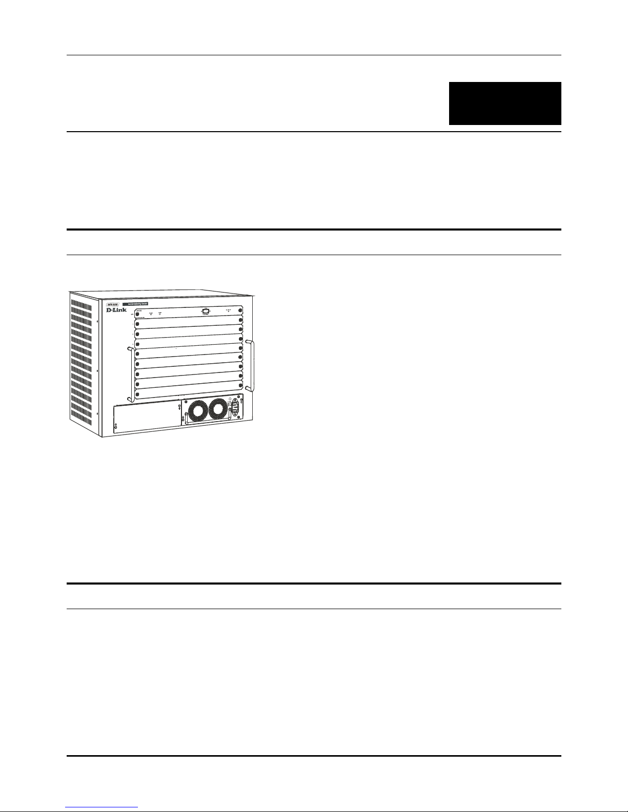
Desktop or Shelf Installation
When installing the Switch on a desktop or shelf, the rubber feet included with the device must be first
attached. Attach these cushioning feet on the bottom at each corner of the device. Allow enough
ventilation space between the device and the objects around it.
Modular L3 Ethernet Switch User’s Guide
12
Figure 2- 1. Switch installed on a Desktop or Shelf
Rack Installation
The Switch can be mounted in an EIA standard size, 19-inch rack, which can be placed in a wiring
closet with other equipment. To install, attach the mounting brackets on the Switch’s front panel (one
on each side) and secure them with the screws provided.
Figure 2- 2. Attaching the mounting brackets to the Switch
Then, use the screws provided with the equipment rack to mount the Switch in the rack.
Installing Modules
The DES-6300 supports up to 6 modules that can be installed into the module bays. Networking
modules are warm-swappable, meaning they can be added and removed while power to the switch is

Modular L3 Ethernet Switch User’s Guide
13
ON. After warm-swapping a networking module, the switch will automatically be rebooted. Make sure to
use the Save Changes command to save the current configuration to NV-RAM before warm-swapping
modules. The CPU module, however, is NOT hot-swappable. Removing or inserting the CPU module
while the power is on may cause irreparable damage to the module and/or to the Switch itself. Further,
make sure you have unplugged the power cord from the removable power supply module before
inserting or removing it from the Switch.
CAUTION: Due to the high energy present in this system, extreme caution should be
exercised whenever adding or removing system components. No element of this
system may be installed or removed except by an authorized technician.
Figure 2- 3. Removing a Blank Slot Cover
Modules can be installed into any free slot, except the CPU module. The CPU module must be installed
in the uppermost (top) slot. To install a module, simply remove a blank slot cover and slide the module
along the guide rails until it snaps firmly in place.
Figure 2- 4. Installing a Module

Modular L3 Ethernet Switch User’s Guide
14
Connecting a Terminal
The DES-6300 can perform basic switching functions without special configuration, but to use the
Switch’s advanced features you must first configure the unit through a terminal (a VT-100 serial data
terminal or a computer running a VT-100 emulator). The connection is made through the Switch’s
Diagnostic RS-232 port, which is configured at the factory as follows:
♦ Baud Rate: 115200
♦ Data Bits: 8
♦ Parity: none
♦ Stop Bits: 1
♦ Flow Control: none
The RS-232 port has a nine-socket D-shell connector with IBM-type DCE wiring, and can be connected
to the terminal using an off-the-shelf RS-232 cable with the proper connectors for the terminal and the
DES-6300.
Power on
Power up the DES-6300 as follows:
♦ Make sure the power module is properly installed in the device.
♦ Plug the device end of the supplied power cord firmly into the power inlet on the DES-6300’s
front panel of the redundant power supply.
♦ Plug the outlet end of the power cord firmly into a suitable AC outlet.
♦ Observe the DES-6300’s LED indicators to make sure the Switch is operating correctly.
The DES-6300’s LED indicators operate as follows during a normal power-up:
♦ All indicators blink momentarily to indicate a system reset.
♦ The Power indicator flashes for about 20 seconds while the switch prepares its run-time
software and performs a self-test.
♦ The Power indicator begins shining steadily, and the remaining indicators begin reflecting port
and system status.
Power Failure
As a precaution, the Switch should be unplugged in case of an impending power failure. When power is
resumed, plug the Switch back in.
Modular L3 Ethernet Switch User’s Guide
15
3
IDENTIFYING EXTERNAL COMPONENTS
This chapter describes the front panel, side panels, optional plug-in modules, and LED indicators of the
Switch.
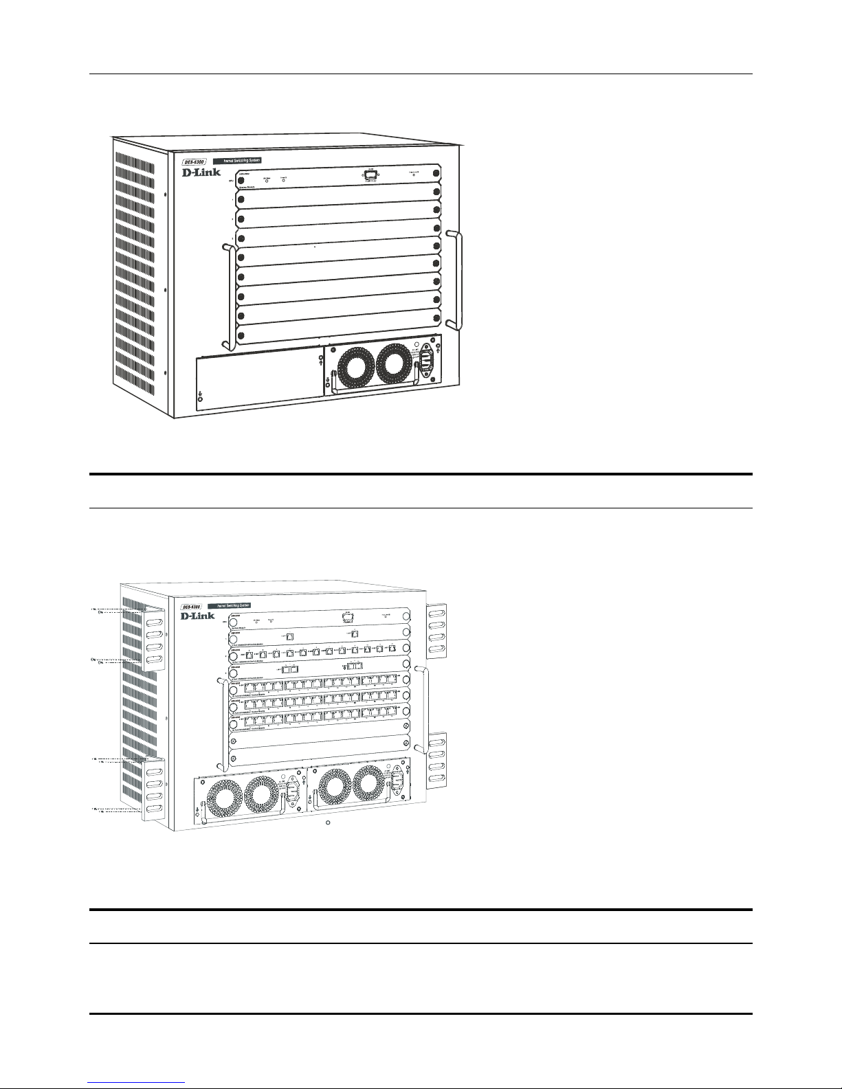
Front Panel
The front panel of the Switch consists nine slide-in module slots for networking modules, two slide-in
module slots for power supply modules, an RS-232 communication port, and LED indicators.
Figure 3- 1. Front panel view of the Switch
The front panel features:
♦ Comprehensive LED indicators display the conditions of the Switch and status of the network. A
description of these LED indicators follows (see LED Indicators).
♦ An RS-232 DCE console port is used to diagnose the Switch via a connection to a terminal (or PC)
and Local Console Management.
♦ Seven slide-in module slots installing networking modules and the CPU module.
♦ Two slide-in module slots for installing power supply modules.
Side Panels
The left side panel of the Switch contains four system fans. The right side panel contains heat vents.
The system fans are used to dissipate heat. The sides of the system also provide heat vents to serve the
same purpose. Do not block these openings, and leave adequate space at the rear and sides of the
Switch for proper ventilation. Be reminded that without proper heat dissipation and air circulation,
system components might overheat, which could lead to system failure.
Modular L3 Ethernet Switch User’s Guide
16
Optional Plug-in Modules
The DES-6300 Modular Ethernet Switch is able to accommodate a range of plug-in modules in order to
increase functionality and performance.
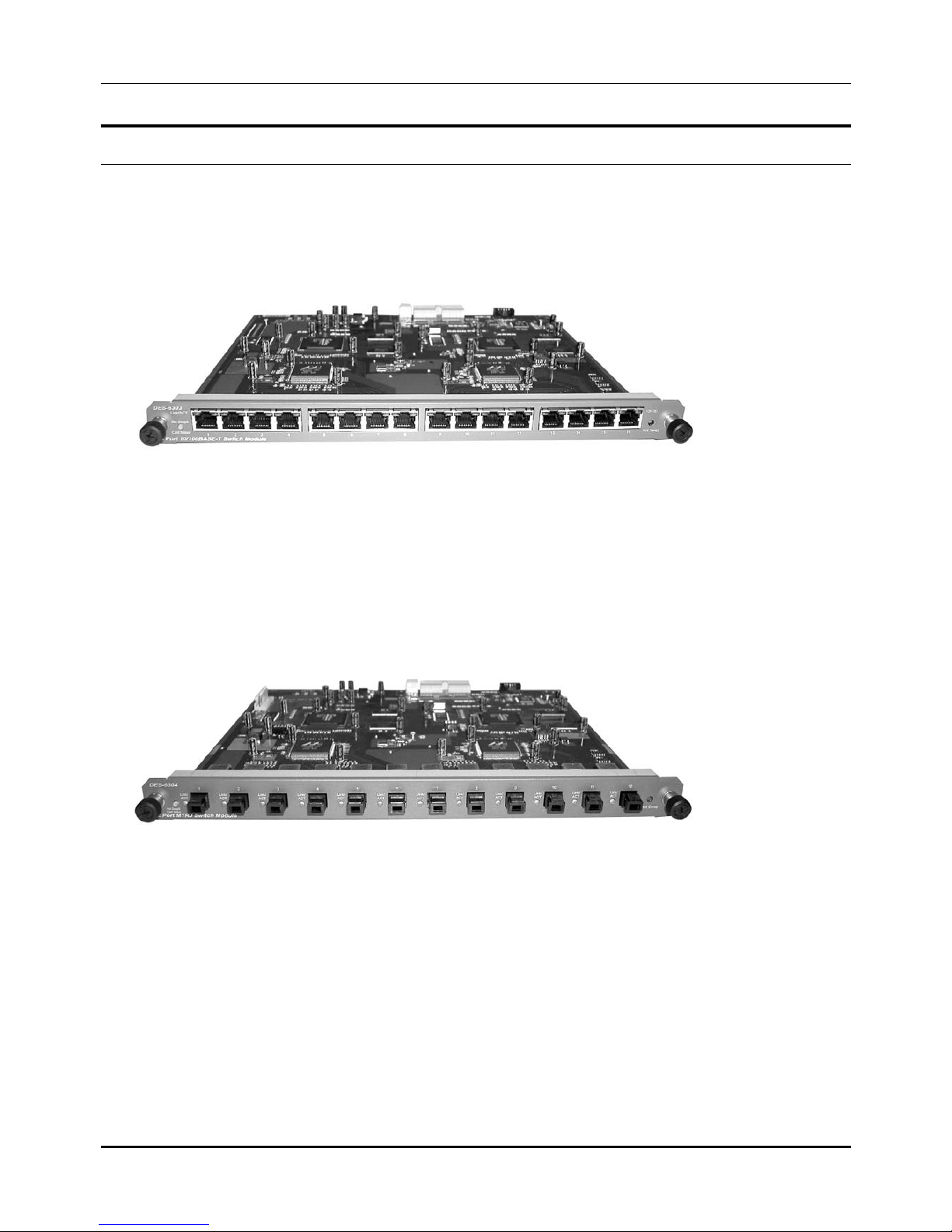
DES-6303 10BASE-T/100BASE-TX Module
Figure 3- 2. Sixteen-port, 10/100BASE-TX module
♦ Sixteen-port, front-panel module
♦ Connects to 10BASE-T and 100BASE-TX devices at full- or half-duplex
♦ Supports Category 3, 4, 5 or better UTP or STP connections of up to 100 meters each
DES-6304 100BASE-FX (MT-RJ) Module
Figure 3- 3. Twelve-port, 100BASE-FX (MT-RJ) module
♦ Twelve-port, front-panel module
♦ Connects to 100BASE-FX devices at full- or half-duplex
♦ Twelve 100BASE-FX (MT-RJ) Fast Ethernet ports
♦ Fully compliant with IEEE 802.3u 100BASE-FX
♦ IEEE 802.3x compliant Flow Control support for full duplex

Modular L3 Ethernet Switch User’s Guide
17
DES-6305 100BASE-FX (SC) Gigabit Module
Figure 3- 4. Eight-port, 100BASE-FX (SC) module
♦ Eight-port, front panel module
♦ Connects to a 100BASE-FX device at full duplex
♦ Eight 100BASE-FX (SC) ports
♦ Fully compliant with IEEE 802.3u
♦ Supports full-duplex operation only
♦ IEEE 802.3x-compliant Flow Control support
DES-6306 1000BASE-SX (SC) Gigabit Module
Figure 3- 5. Two-port, 1000BASE-SX gigabit module
♦ Two-port, front-panel module
♦ Connects to 1000BASE-SX devices at full duplex
♦ Two 1000BASE-SX (SC) Gigabit Ethernet ports
♦ Fully compliant with IEEE 802.3z
♦ Support full-duplex operation only
♦ IEEE 802.3x-compliant Flow Control support
Modular L3 Ethernet Switch User’s Guide
18
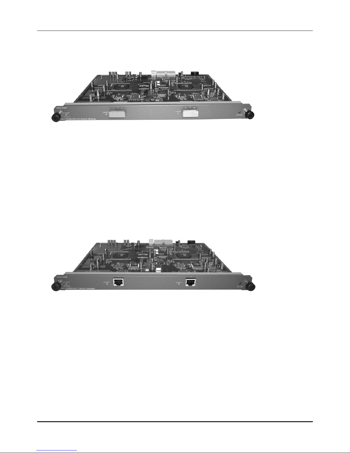
DES-6307 1000BASE-LX (SC) Gigabit Module
Figure 3- 6. Two-port, 1000BASE-LX gigabit module
♦ Two-port, front-panel module
♦ Connects to 1000BASE-LX devices at full duplex
♦ Two 1000BASE-LX (SC) Gigabit Ethernet ports
♦ Fully compliant with IEEE 802.3z
♦ Supports full-duplex operation only
♦ IEEE 802.3x-compliant Flow Control support
DES-6308 1000BASE-T (RJ-45) Module
Figure 3- 7. Two-port, 1000BASE-T (RJ-45) module
♦ Two-port, front-panel module
♦ Connects to 1000BASE-T devices only at full duplex and auto-negotiating
♦ Two auto-sensing 10/100/1000 Mbps ports
♦ Fully compliant with IEEE 802.3ab
♦ Fully compliant with IEEE 802.1Q/P
♦ Back pressure Flow Control support for half-duplex mode
♦ IEEE 802.3x compliant Flow Control support for full duplex

Modular L3 Ethernet Switch User’s Guide
19
DES-6309 GBIC Module
Figure 3- 8. Two-port GBIC Module
♦ Two-port, front-panel module
♦ Connects to GBIC devices at full duplex
♦ Two GBIC Ethernet ports
♦ Fully compliant with IEEE 802.3z
♦ Supports full-duplex operation only
♦ IEEE 802.3x-compliant Flow Control support
Power Supply Modules
♦ Dual power modules design with current sharing design
♦ Full redundant feature design to ensure continuous operation—if one power module fails, the
other will take over all current supply automatically
♦ Hot-swappable/Hot-pluggable capability
♦ Power management functions
♦ Input: 90 ~ 264 VAC, 47 ~ 63Hz
♦ Output: 3.3V 80A maximum, 12V 2A maximum
LED Indicators
The LED indicators of the Switch include CPU Status and Power OK. The following shows the LED
indicators for the Switch along with an explanation of each indicator.
Figure 3- 9. CPU Front Panel LED Indicators
♦ CPU Status – This center indicator on the front panel displays the current status of the switch. The
LED will blink while the Power-On Self-Test (POST) is running during startup. It will light a steady
green after the POST test to indicate the switch is powered on and operating properly. It will light amber
when an error occurs during startup and the switch is therefore not functioning.

Modular L3 Ethernet Switch User’s Guide
20
♦ Power OK – This indicator lights green when the CPU module of the switch is receiving power and
functioning properly.

Modular L3 Ethernet Switch User’s Guide
21
4
CONNECTING THE SWITCH
This chapter describes how to connect the Switch to your Ethernet network as well as providing an
informational cable length table.
Switch to End Node
End nodes include PCs outfitted with a Network Interface Card (NIC) and most routers. For twisted-pair
(copper) connections, the RJ-45 UTP ports on NICs and most routers are MDI-II. When using a normal
straight-through cable, an MDI-II port must connect to an MDI-X port.
An end node can be connected to the Switch via a two-pair Category 3, 4, 5 UTP/STP straight cable (be
sure to use Category 5 UTP or STP cabling for 100BASE-TX Fast Ethernet connections). The end node
should be connected to any of the sixteen ports (1x - 16x) on the 10BASE-T/100BASE-TX module. The
LED indicators for the port the end node is connected to are lit according to the capabilities of the NIC.
If LED indicators are not illuminated after making a proper connection, check the PC’s LAN card, the
cable, switch conditions, and connections.
The following LED indicator states are possible for an end node to switch connection:
1. The 100M indicator comes ON for a 100 Mbps and stays OFF for 10 Mbps.
2. The Link/Act indicator lights up upon hooking up a PC that is powered on.
Switch to Hub or Switch
These connections can be accomplished in a number of ways. For twisted-pair (copper) connections, the
most important consideration is that when using a normal, straight-through cable, the connection
should be made between a normal crossed port (Port 1x, 2x, etc.) and an Uplink (MDI-II) port. If you are
using a crossover cable, the connection can be made from a normal crossed port to another crossed
port.
♦ A 10BASE-T hub or switch can be connected to the Switch via a two-pair Category 3, 4 or 5 UTP/STP
straight cable.
♦ A 100BASE-TX hub or switch can be connected to the Switch via a four-pair Category 5 UTP/STP
straight cable.
If the other switch or hub contains an unused Uplink port, we suggest connecting the other device’s
Uplink (MDI-II) port to any of the switch’s (MDI-X) ports (1x - 16x 100BASE-TX ports).
If the other device does not have an unused Uplink port, make the connection with a crossover cable
from any of the twisted-pair ports on the switch to any normal twisted-pair port on the hub.
10BASE-T Device
For a 10BASE-T device, the Switch’s LED indicators should display the following:
♦ 100M speed indicator is OFF.

Modular L3 Ethernet Switch User’s Guide
22
♦ Link/Act indicator is ON.
100BASE-TX Device
For a 100BASE-TX device, the Switch’s LED indicators should display the following:
♦ 100M speed indicator is ON.
♦ Link/Act indicator is ON.
1000BASE-T Device
For a 1000BASE-T device, the Switch’s LED indicators should display the following:
♦ Link/Act indicator is ON.
100BASE-FX Device
For a 100BASE-FX device, the Switch’s LED indicators should display the following:
♦ Link/Act indicator is ON.
1000BASE-SX Device
For a 1000BASE-SX device, the Switch’s LED indicators should display the following:
♦ Link/Act indicator is ON.
1000BASE-LX Device
For a 1000BASE-LX device, the Switch’s LED indicators should display the following:
♦ Link/Act indicator is ON.
Cable Lengths
Standard
Media Type
MHz/km
Rating
Maximum
Distance
1000BASE-SX
50/125µm Multimode Fiber 400 500 Meters
50/125µm Multimode Fiber 500 550 Meters
62.5/125µm Multimode
Fiber
160 220 Meters
62.5/125µm Multimode
Fiber
200 275 Meters
1000BASE-LX
50/125µm Multimode Fiber 400 500 Meters
50/125µm Multimode Fiber 500 550 Meters
62.5/125µm Multimode
Fiber
500 550 Meters
10µ Single-mode Fiber 5000 Meters
1000BASE-T
Category 5e UTP Cable
(1000Mbps)
100 Meters
100BASE-FX
50/125µm Multimode Fiber
(half-duplex operation)
400 Meters

Modular L3 Ethernet Switch User’s Guide
23
50/125µm Multimode Fiber
(full-duplex operation)
2000 Meters
62.5/125µm Multimode
Fiber
(half-duplex operation)
400 Meters
52.5/125µm Multimode
Fiber
(full-duplex operation)
2000 Meters
100BASE-TX
Category 5 UTP Cable
(100Mbps)
100 Meters
10BASE-T
Category 3 UTP Cable
(10Mbps)
100 Meters
Table 4-1. Cable Lengths

Modular L3 Ethernet Switch User’s Guide
24
5
SWITCH MANAGEMENT CONCEPTS
This chapter discusses many of the features used to manage the switch, and explains many concepts
and important points regarding these features. Configuring the Switch to implement these concepts is
discussed in detail in the next chapters.
IP Addresses and SNMP Community Names
Each Switch has its own IP Address, which is used for communication with an SNMP network manager
or other TCP/IP application (for example BOOTP, TFTP, etc.). You must provide the switch with an IP
Address to meet the specification of your networking address scheme.
In addition, you can also set an IP Address for a gateway router. This becomes necessary when the
network management station is located on a different IP network as the Switch, making it necessary for
management packets to go through a router to reach the network manager, and vice-versa.
For security, you can set in the Switch a list of IP Addresses of the network managers that you allow to
manage the Switch. You can also change the default Community Name in the Switch and set access
rights of these Community Names.
Traps
Traps are messages that alert you of events that occur on the Switch. The events can be as serious as a
reboot (someone accidentally turned OFF the Switch), or less serious like a port status change. The
Switch generates traps and sends them to the network manager (trap managers). The following lists the
types of events that can take place on the Switch.
◊ System resets
◊ Errors
◊ Status changes
◊ Topology changes
◊ Operation
You can also specify which network managers may receive traps from the Switch by setting a list of IP
Addresses of the authorized network managers.
Trap managers are special users of the network who are given certain rights and access in overseeing
the maintenance of the network. Trap managers will receive traps sent from the Switch; they must
immediately take certain actions to avoid future failure or breakdown of the network.
The following are trap types a trap manager will receive:
♦ Cold Start – This trap signifies that the Switch has been powered up and initialized such that
software settings are reconfigured and hardware systems are rebooted. A cold start is different from a
factory reset.

Modular L3 Ethernet Switch User’s Guide
25
♦ Authentication Failure – This trap signifies that someone has tried to logon to the switch using an
invalid SNMP community name. The switch automatically stores the source IP address of the
unauthorized user.
♦ Link Change Event – This trap is sent whenever the link of a port changes from link up to link down
or from link down to link up.
♦ Power Fan1 Failure – This trap is sent whenever one of the two fans on a redundant power supply
module fails.
♦ Power Fan2 Failure – This trap is sent whenever one of the two fans on a redundant power supply
module fails.
♦ End TFTP – This trap is sent when TFTP service ends.
♦ Abort TFTP – This trap is sent when TFTP service aborts.
♦ Start TFTP – This trap is sent when TFTP service starts.
♦ VLAN Dynamic Port Added – This trap is sent when a VLAN dynamic port is added.
♦ VLAN Dynamic Port Removed – This trap is sent when a VLAN dynamic port is removed.
MIBs
Management information and counters are stored in the Switch in the Management Information Base
(MIB). The Switch uses the standard MIB-II Management Information Base module. Consequently,
values for MIB objects can be retrieved from any SNMP-based network manager software. In addition to
the standard MIB-II, the Switch also supports its own proprietary enterprise MIB as an extended
Management Information Base. These MIBs may also be retrieved by specifying the MIB’s ObjectIdentity (OID) at the network manager. MIB values can be either read-only or read-write.
Read-only MIBs variables can be either constants that are programmed into the Switch, or variables
that change while the Switch is in operation. Examples of read-only constants are the number of ports
and types of ports. Examples of read-only variables are the statistics counters such as the number of
errors that have occurred, or how many kilobytes of data have been received and forwarded through a
port.
Read-write MIBs are variables usually related to user-customized configurations. Examples of these are
the Switch’s IP Address, Spanning Tree Algorithm parameters, and port status.
If you use a third-party vendors’ SNMP software to manage the Switch, a diskette listing the Switch’s
propriety enterprise MIBs can be obtained by request. If your software provides functions to browse or
modify MIBs, you can also get the MIB values and change them (if the MIBs’ attributes permit the write
operation). This process however can be quite involved, since you must know the MIB OIDs and retrieve
them one by one.
Packet Forwarding
The Switch learns the network configuration and uses this information to forward packets. This reduces
the traffic congestion on the network, because packets, instead of being transmitted to all segments, are
transmitted to the destination only. Example: if Port 1 receives a packet destined for a station on Port
2, the Switch transmits that packet through Port 2 only, and transmits nothing through the other ports.

Modular L3 Ethernet Switch User’s Guide
26
Aging Time
The Aging Time is a parameter that affects the auto-learn process of the Switch in terms of the network
configuration. Dynamic Entries, which make up the auto-learned-node address, are aged out of the
address table according to the Aging Time that you set.
The Aging Time can be from 10 seconds to 9999 seconds. A very long Aging Time can result with the
out-of-date Dynamic Entries that may cause incorrect packet filtering/forwarding decisions.
On the other hand, if the Aging Time is too short, many entries may be aged out soon, resulting in a
high percentage of received packets whose source addresses cannot be found in the address table, in
which case the Switch will broadcast the packet to all ports, negating many of the benefits of having a
switch.
Filtering Database
A switch uses a filtering database to segment the network and control communications between
segments. It also filters packets off the network for intrusion control (MAC Address filtering).
For port filtering, each port on the switch is a unique collision domain and the switch filters (discards)
packets whose destination lies on the same port as where it originated. This keeps local packets from
disrupting communications on other parts of the network.
For intrusion control, whenever a switch encounters a packet originating from or destined to a MAC
address defined by the user, the switch will discard the packet.
Filtering includes:
Dynamic filtering – Automatic learning and aging of MAC addresses and their location on the network.
Filtering occurs to keep local traffic confined to its segment.
MAC address filtering – The manual entry of specific MAC addresses to be filtered from the network.
Filtering done by the Spanning Tree Protocol – Able to filter packets based on topology, making sure
that signal loops don’t occur.
Filtering done for VLAN integrity – Packets from a member of a VLAN (VLAN 2, for example) destined
for a device on another VLAN (VLAN 3) will be filtered.
Spanning Tree Algorithm
The Spanning Tree Algorithm (STA) in the Switch allows you to create alternative paths (with multiple
switches or other types of bridges) in your network. These backup paths are idle until the Switch
determines that a problem has developed in the primary paths. When a primary path is lost, the switch
providing the alternative path will automatically go into service with no operator intervention. This
automatic network reconfiguration provides maximum uptime to network users. The concept of the
Spanning Tree Algorithm is a complicated and complex subject and must be fully researched and
understood. Please read the following before making any changes.
Network loop detection and prevention – With STA, there will be only one path between any two LANs. If
there is more than one path, forwarded packets will loop indefinitely. STA detects any looped path and
selects the path with the lowest path cost as the active path, while blocking the other path and using it
as the backup path.
Automatic topology re-configuration – When the path for which there is a backup path fails, the backup
path will be automatically activated, and STA will automatically re-configure the network topology.

Modular L3 Ethernet Switch User’s Guide
27
STA Operation Levels
STA operates on two levels: the bridge level and the port level. On the bridge level, STA calculates the
Bridge Identifier for each Switch, then sets the Root Bridge and the Designated Bridges. On the port
level, STA sets the Root Port and Designated Ports. Details are as follows:
On the Bridge Level
Root Bridge – The switch with the lowest Bridge Identifier is the Root Bridge. Naturally, you will want
the Root Bridge to be the best switch among the switches in the loop to ensure the highest network
performance and reliability.
Bridge Identifier – This is the combination of the Bridge Priority (a parameter that you can set) and the
MAC address of the switch. Example: 4 00 80 c8 00 01 00, where 4 is the Bridge Priority. A lower
Bridge Identifier results in a higher priority for the switch, and thus increases it probably of being
selected as the Root Bridge.
Designated Bridge – From each LAN segment, the attached Bridge that has the lowest Root Path Cost
to the Root Bridge is the Designated Bridge. It forwards data packets for that LAN segment. In cases
where all Switches have the same Root Path Cost, the switch with the lowest Bridge Identifier becomes
the Designated Bridge.
Root Path Cost – The Root Path Cost of a switch is the sum of the Path Cost of the Root Port and the
Root Path Costs of all the switches that the packet goes through. The Root Path Cost of the Root Bridge
is zero.
Bridge Priority – This is a parameter that users can set. The smaller the number you set, the higher
the Bridge Priority is. The higher the Bridge Priority, the better the chance the Switch will be selected as
the Root Bridge.
On the Port Level
Root Port – Each switch has a Root Port. This is the port that has the lowest Path Cost to the Root
Bridge. In case there are several such ports, then the one with the lowest Port Identifier is the Root Port.
Designated Port – This is the port on each Designated Bridge that is attached to the LAN segment for
which the switch is the Designated Bridge.
Port Priority – The smaller this number, the higher the Port Priority is. With higher Port Priority, the
higher the probability that the port will be selected as the Root Port.
Path Cost – This is a changeable parameter and may be modified according to the STA specification.
The 1000Mbps segment has an assigned Path Cost of 4, the 100Mbps segment has an assigned Path
Cost of 19, and each 10Mbps segment has an assigned Path Cost of 100, based on the STA
specifications.
User-Changeable STA Parameters
The factory default setting should cover the majority of installations. However, it is advisable to keep the
default settings as set at the factory, unless it is absolutely necessary. The user changeable parameters
in the Switch are as follows:
Bridge Priority – A Bridge Priority can be from 0 to 65535. 0 is equal to the highest Bridge Priority.
Bridge Hello Time – The Hello Time can be from 1 to 10 seconds. This is the interval between two
transmissions of BPDU packets sent by the Root Bridge to tell all other Switches that it is indeed the
Root Bridge. If you set a Hello Time for your Switch, and it is not the Root Bridge, the set Hello Time will
be used if and when your Switch becomes the Root Bridge.
Note: The Hello Time cannot be longer than the Max. Age. Otherwise, a configuration error will
occur.
Modular L3 Ethernet Switch User’s Guide
28
Bridge Max. Age – The Max. Age can be from 6 to 40 seconds. At the end of the Max. Age, if a BPDU
has still not been received from the Root Bridge, your Switch will start sending its own BPDU to all
other Switches for permission to become the Root Bridge. If it turns out that your Switch has the lowest
Bridge Identifier, it will become the Root Bridge.
Bridge Forward Delay – The Forward Delay can be from 4 to 30 seconds. This is the time any port on
the Switch spends in the listening state while moving from the blocking state to the forwarding state.
Observe the following formulas when you set the above parameters:
Max. Age ≤ 2 x (Forward Delay - 1 second)
Max. Age ≥ 2 x (Hello Time + 1 second)
Port Priority – A Port Priority can be from 0 to 255. The lower the number, the greater the probability
the port will be chosen as the Root Port.
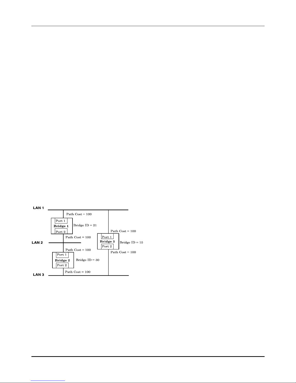
Illustration of STA
A simple illustration of three Bridges (or the Switch) connected in a loop is depicted in Figure 5-1. In
this example, you can anticipate some major network problems if the STA assistance is not applied. For
instance, if Bridge 1 broadcasts a packet to Bridge 2, Bridge 2 will broadcast it to Bridge 3, and Bridge
3 will broadcast it to Bridge 1 and so on. The broadcast packet will be passed indefinitely in a loop,
causing a serious network failure.
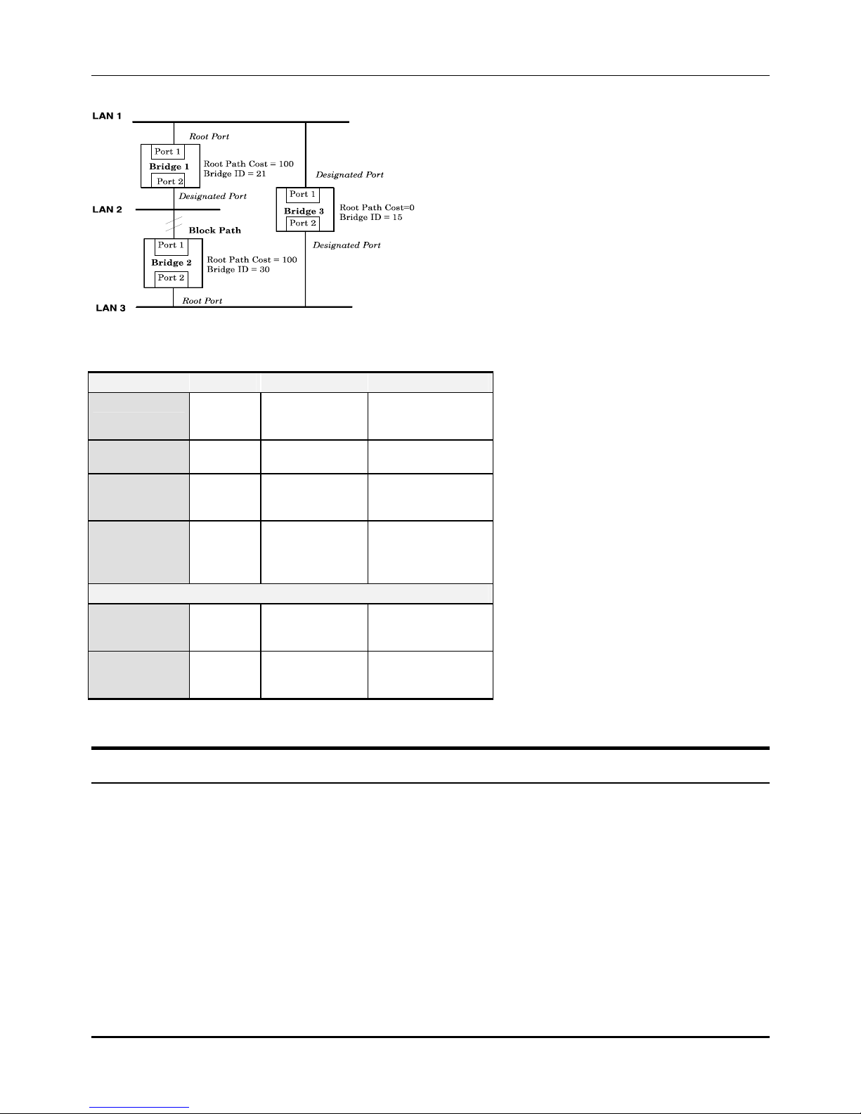
To alleviate network loop problems, STA can be applied as shown in Figure 5-2. In this example, STA
breaks the loop by blocking the connection between Bridge 1 and 2. The decision to block a particular
connection is based on the STA calculation of the most current Bridge and Port settings. Now, if Bridge
1 broadcasts a packet to Bridge 3, then Bridge 3 will broadcast it to Bridge 2 and the broadcast will end
there.
STA setup can be somewhat complex. Therefore, you are advised to keep the default factory settings
and STA will automatically assign root bridges/ports and block loop connections. However, if you need
to customize the STA parameters, refer to Table 5-1.
Figure 5- 1. Before Applying the STA Rules
Modular L3 Ethernet Switch User’s Guide
29
Figure 5- 2. After Applying the STA Rules
STA parameters Settings Effects Comment
Bridge Priority
lower the #,
higher the
priority
Increases chance of
becoming the Root
Bridge
Avoid, if the switch is
used in workgroup level
of a large network
Hello Time
1 - 10 sec.
No effect, if not
Root Bridge
Never set greater than
Max. Age Time
Max. Age Time
6 - 40 sec.
Compete for Root
Bridge, if BPDU is
not received
Avoid low number for
unnecessary reset of
Root Bridge
Forward Delay
4 - 30 sec.
High # delays the
change in state
Max. Age ≤ 2 x
(Forward Delay - 1)
Max. Age ≥ 2 x (Hello
Time + 1)
Port Level STA parameters
Enable/Disable
Enable/
Disable
Enable or disable
this LAN segment
Disable a port for
security or problem
isolation
Port Priority
lower the #,
higher the
priority
Increases chance of
become Root Port
Table 5-1. User-selective STA parameters
Port Trunking
Port trunking is used to combine a number of ports together to make a single high-bandwidth data
pipeline. The participating parts are called members of a trunk group, with one port designated as the
anchor of the group. Since all members of the trunk group must be configured to operate in the same
manner, all settings changes made to the anchor port are applied to all members of the trunk group.
Thus, when configuring the ports in a trunk group, you only need to configure the anchor port.
The Switch supports up to 16 trunk groups. Each module on the switch supports up to two trunk
groups except gigabit modules, which support a single trunk group. The Switch treats all ports in a
trunk group as a single port. As such, trunk ports will not be blocked by Spanning Tree.
Data transmitted to a specific host (destination address) will always be transmitted over the same port
in a trunk group. This allows packets in a data stream to arrive in the same order they were sent. A
trunk connection can be made with any other switch that maintains host-to-host data streams over a

Modular L3 Ethernet Switch User’s Guide
30
single trunk port. Switches that use a load-balancing scheme that sends the packets of a host-to-host
data stream over multiple trunk ports cannot have a trunk connection with the Switch.
VLANs & Broadcast Domains
VLANs are a collection of users or switch ports grouped together in a secure, autonomous broadcast
and multicast domain. The main purpose of setting up VLANs on a network is to limit the range and
effects of broadcast packets, which can develop into broadcast storms and seriously impair network
performance.
Three types of VLANs and broadcast domains are implemented on the switch: 802.1Q VLANs, portbased VLANs, and MAC-based broadcast domains. Only one of the three types can be active on the
switch at any given time, however. Thus, you will need to choose the type of VLAN or broadcast domain
you wish to setup on your network and configure the switch accordingly. MAC-based broadcast
domains and port-based VLANs are limited to the switch and devices directly connected to it, while
802.1Q VLANs support IEEE 802.1Q tagging, which enables them to span the entire network (assuming
all switches on the network are IEEE 802.1Q-compliant).
All VLANs allow a network to be segmented in order to reduce the size of broadcast domains. All
broadcast, multicast, and unknown packets entering the switch on a particular VLAN or broadcast
domain will only be forwarded to the stations (MAC-based) or ports (802.1Q and Port-based) that are
members of that VLAN or broadcast domain. 802.1Q VLANs can also be setup to limit unicast packets
to members of a particular VLAN, thus providing a degree of security to your network.
Another benefit of 802.1Q and port-based VLANs is that you can change the network topology without
physically moving stations or changing cable connections. Stations can be ‘moved’ to another VLAN and
thus communicate with members and share resources on the new VLAN, simply by changing the port
VLAN settings from one VLAN (the sales VLAN, for example) to another VLAN (the marketing VLAN).
This allows VLANs to accommodate network moves, changes and additions with the utmost flexibility.
MAC-based broadcast domains, on the other hand, allow a station to be physically moved yet still
belong to the same broadcast domain without having to change configuration settings.
The untagging feature of IEEE 802.1Q VLANs allows VLANs to work with legacy switches and NICs that
don’t recognize VLAN tags in packet headers. The tagging feature allows VLANs to span multiple
802.1Q-compliant switches through a single physical connection and allows Spanning Tree to be
enabled on all ports and work normally.
MAC-based Broadcast Domains
The Switch supports up to 12 MAC-based broadcast domains, which are by their nature, limited to the
switch itself and the devices connected directly to it.
Since MAC addresses are hard-wired into a station’s network interface card (NIC), MAC-based
broadcast domains enable network managers to move a station to a different physical location on the
network and have that station automatically retain its broadcast domain membership. This provides the
network with a high degree of flexibility since even notebook PC’s can plug into any available port on a
network and communicate with the same people and use the same resources that have been allocated
to the broadcast domain in which it is a member.
Since MAC-based broadcast domains do not restrict the transmission of known unicast frames to other
broadcast domains, they can only be used to define limited broadcast domains. As such, they are best
implemented on networks where stations are frequently moving, for example where people using
notebook PCs are constantly plugging into different parts of the network.
Setting up MAC-based broadcast domains is a relatively straight-forward process. Simply create the
broadcast domain by assigning it a name (description) and add MAC addresses for the stations that will
be members.
 Loading...