

Page 1
User Manual
Product Model:
Layer 3 Stackable Fast Ethernet Managed Switch
Release 4. 5
DES-3800 Series
©Copyright 2008. All rights reserved.
Page 2

xStack DES-3800 Series Layer 3 Stackable Fast Ethernet Managed Switch
_____________________________________________________________________________
Information in this document is subject to change without notice.
© 2008 D-Link Computer Corporation. All rights reserved.
Reproduction in any manner whatsoever without the written permission of D-Link Computer Corporation is strictly forbidden.
Trademarks used in this text: D-Link and the D-LINK logo are trademarks of D-Link Computer Corporation; Microsoft and Windows are registered trademarks of
Microsoft Corporation.
Other trademarks and trade names may be used in this document to refer to either the entities claiming the marks and names or their products. D-Link Computer
Corporation disclaims any proprietary interest in trademarks and trade names other than its own.
June 2008 P/N 651ES3800055G
ii
Page 3

xStack DES-3800 Series Layer 3 Stackable Fast Ethernet Managed Switch
Table of Contents
Preface ........................................................................................................................................................................................... x
Intended Readers........................................................................................................................................................................... xi
Typographical Conventions..........................................................................................................................................................xi
Notes, Notices, and Cautions........................................................................................................................................................xi
Safety Instructions .......................................................................................................................................................................xii
Safety Cautions............................................................................................................................................................................................ xii
General Precautions for Rack-Mountable Products .................................................................................................................................... xiii
Protecting Against Electrostatic Discharge..................................................................................................................................................xiv
Introduction......................................................................................................................................................1
xStack DES-3800 Series................................................................................................................................................................ 1
Gigabit Ethernet Technology..........................................................................................................................................................................1
Switch Description..........................................................................................................................................................................................1
Features...........................................................................................................................................................................................................2
Ports................................................................................................................................................................................................................3
Front-Panel Components.................................................................................................................................................................................2
Rear Panel Description....................................................................................................................................................................................6
Side Panel Description....................................................................................................................................................................................7
Gigabit Ports ...................................................................................................................................................................................................7
Installation........................................................................................................................................................8
Package Contents............................................................................................................................................................................................8
Before You Connect to the Network...............................................................................................................................................................8
Installing the Switch without the Rack............................................................................................................................................................9
Installing the Switch in a Rack........................................................................................................................................................................9
Mounting the Switch in a Standard 19" Rack................................................................................................................................................10
Wall Mounting the DES-3828P ....................................................................................................................................................................11
Connecting DC Power to the DES-3828DC..................................................................................................................................................12
RPS Installation.............................................................................................................................................................................................13
Connecting the Switch...................................................................................................................................17
Switch to End Node ......................................................................................................................................................................................17
Switch to Hub or Switch...............................................................................................................................................................................18
Connecting To Network Backbone or Server................................................................................................................................................19
Introduction to Switch Management ...........................................................................................................20
Management Options................................................................................................................................................................... 20
Web-based Management Interface................................................................................................................................................................20
SNMP-Based Management .......................................................................................................... .................................................................20
Connecting the Console Port (RS-232 DCE)................................................................................................................................................20
First Time Connecting to the Switch.............................................................................................................................................................22
Password Protection......................................................................................................................................................................................23
SNMP Settings..............................................................................................................................................................................................24
IP Address Assignment.................................................................................................................................................................................25
iii
Page 4

xStack DES-3800 Series Layer 3 Stackable Fast Ethernet Managed Switch
Web-based Switch Configuration.................................................................................................................27
Introduction.................................................................................................................................................................................. 27
Login to Web Manager .................................................................................................................................................................................27
Web-based User Interface.............................................................................................................................................................................28
Web Pages.....................................................................................................................................................................................................29
Administration...............................................................................................................................................30
Device Information...................................................................................................................................................................... 31
IP Address.................................................................................................................................................................................... 33
Port Configuration........................................................................................................................................................................36
Port Settings.................................................................................................................................................................................................. 36
Port Description............................................................................................................................................................................................38
PoE Configuration........................................................................................................................................................................39
User Accounts.............................................................................................................................................................................. 40
Port Mirroring.............................................................................................................................................................................. 42
System Log Settings.....................................................................................................................................................................43
System Severity Settings.............................................................................................................................................................. 45
SNTP Settings.............................................................................................................................................................................. 46
Time Settings................................................................................................................................................................................................46
Time Zone and DST......................................................................................................................................................................................47
MAC Notification Settings ..........................................................................................................................................................49
TFTP Services.............................................................................................................................................................................. 50
Multiple Image Services .............................................................................................................................................................. 51
Firmware Information...................................................................................................................................................................................51
Dual Configuration Services........................................................................................................................................................ 52
Ping Test...................................................................................................................................................................................... 53
SNMP Manager ........................................................................................................................................................................... 54
SNMP Settings..............................................................................................................................................................................................54
SNMP User Table.........................................................................................................................................................................................55
SNMP View Table........................................................................................................................................................................................57
SNMP Group Table.......................................................................................................................................................................................58
SNMP Community Table Configuration.......................................................................................................................................................59
SNMP Host Table.........................................................................................................................................................................................60
SNMP Engine ID..........................................................................................................................................................................................62
SNMP Trap Settings.....................................................................................................................................................................................62
D-Link Single IP Management.................................................................................................................................................... 63
Single IP Management (SIM) Overview.......................................................................................................................................................63
SIM Using the Web Interface........................................................................................................................................................................64
Topology.......................................................................................................................................................................................................66
Tool Tips.......................................................................................................................................................................................................68
Right Click....................................................................................................................................................................................................69
Menu Bar ......................................................................................................................................................................................................71
Packet to CPU Settings................................................................................................................................................................ 72
Layer 2 Features ............................................................................................................................................73
iv
Page 5

xStack DES-3800 Series Layer 3 Stackable Fast Ethernet Managed Switch
VLANs......................................................................................................................................................................................... 73
Understanding IEEE 802.1p Priority.............................................................................................................................................................73
VLAN Description........................................................................................................................................................................................73
IEEE 802.1Q VLANs....................................................................................................................................................................................74
Double VLANs.............................................................................................................................................................................................79
Static VLAN Entry........................................................................................................................................................................................80
GVRP Setting................................................................................................................................................................................................84
Double VLAN...............................................................................................................................................................................................85
Trunking........................................................................................................................................................................................................87
Link Aggregation..........................................................................................................................................................................................88
LACP Port Settings............................................................................................................. ..........................................................................90
IGMP ........................................................................................................................................................................................... 91
IGMP Snooping ............................................................................................................................................................................................91
Static Router Port Settings............................................................................................................................................................................93
IGMP Multicast VLAN.................................................................................................................................................................................94
MLD Snooping ............................................................................................................................................................................ 95
MLD Snooping Settings................................................................................................................................................................................96
MLD Snooping Static Router Port Settings ..................................................................................................................................................97
Spanning Tree.............................................................................................................................................................................. 98
STP Bridge Global Settings........................................................................................................................................................................101
MST Configuration Identification...............................................................................................................................................................103
MSTP Port Information...............................................................................................................................................................................105
STP Instance Settings..................................................................................................................................................................................106
STP Port Settings........................................................................................................................................................................................107
STP Ports Information of Instance..............................................................................................................................................................109
Forwarding................................................................................................................................................................................. 110
Unicast Forwarding.....................................................................................................................................................................................110
Multicast Forwarding..................................................................................................................................................................................110
Multicast Port Filtering Mode.....................................................................................................................................................................112
Loopback Detection................................................................................................................................................................... 114
Protocol VLAN...........................................................................................................................................................................................116
Layer 3 Features ..........................................................................................................................................119
IP Multinetting........................................................................................................................................................................... 120
IP Interface Settings....................................................................................................................................................................................120
Loopback IP Interface................................................................................................................................................................ 124
MD5 Key Settings...................................................................................................................................................................... 125
Route Redistribution Settings .................................................................................................................................................... 126
Static/Default Route Settings..................................................................................................................................................... 127
Route Preference Settings.......................................................................................................................................................... 128
Static ARP Table........................................................................................................................................................................ 131
RIP............................................................................................................................................................................................. 132
RIP Global Settings.....................................................................................................................................................................................133
RIP Interface Settings .................................................................................................................................................................................134
OSPF.......................................................................................................................................................................................... 136
v
Page 6

xStack DES-3800 Series Layer 3 Stackable Fast Ethernet Managed Switch
OSPF Global Settings .................................................................................................................................................................................152
OSPF Area Settings.....................................................................................................................................................................................152
OSPF Interface Settings..............................................................................................................................................................................154
OSPF Virtual Link Settings.........................................................................................................................................................................156
OSPF Area Aggregation Settings................................................................................................................................................................158
OSPF Host Route Settings..........................................................................................................................................................................159
OSPF Default Information Originate Settings.............................................................................................................................................160
DHCP Server ............................................................................................................................................................................. 161
DHCP Server Global Settings.....................................................................................................................................................................161
DHCP Server Pool Settings.........................................................................................................................................................................162
DHCP Server Manual Binding Settings ............................................................................................ ..........................................................163
DHCP Server Excluded Address Settings...................................................................................................................................................164
DHCP Server Conflict IP Table..................................................................................................................................................................164
DHCP Server Binding Table.......................................................................................................................................................................165
DHCP/BOOTP Relay ................................................................................................................................................................ 166
DHCP / BOOTP Relay Global Settings......................................................................................................................................................166
DHCP/BOOTP Relay Interface Settings.....................................................................................................................................................169
DNS Relay................................................................................................................................................................................. 170
DNS Relay Global Settings.........................................................................................................................................................................170
DNS Relay Static Settings...........................................................................................................................................................................171
VRRP......................................................................................................................................................................................... 172
VRRP Global Settings.................................................................................................................................................................................172
VRRP Virtual Router Settings....................................................................................................................................................................172
VRRP Authentication Settings....................................................................................................................................................................176
IP Multicast Routing Protocol.................................................................................................................................................... 177
IGMP Interface Settings..............................................................................................................................................................................179
DVMRP Interface Configuration............................................................................................................................................... 181
DVMRP Global Settings.............................................................................................................................................................................181
DVMRP Interface Settings..........................................................................................................................................................................181
PIM Protocol.............................................................................................................................................................................. 183
PIM-SM......................................................................................................................................................................................................183
PIM-DM Interface Configuration ...............................................................................................................................................................184
PIM Global Settings....................................................................................................................................................................................184
PIM Interface Settings.................................................................................................................................................................................184
PIM Candidate BSR Settings......................................................................................................................................................................186
PIM Parameter Settings...............................................................................................................................................................................187
PIM Candidate RP Global Settings.............................................................................................................................................................188
PIM Candidate RP Settings.........................................................................................................................................................................188
PIM Register Checksum Settings................................................................................................................................................................189
PIM Static RP Settings................................................................................................................................................................................190
QoS................................................................................................................................................................191
Advantages of QoS .....................................................................................................................................................................................191
Understanding QoS.....................................................................................................................................................................................192
Bandwidth Control..................................................................................................................................................................... 193
vi
Page 7

xStack DES-3800 Series Layer 3 Stackable Fast Ethernet Managed Switch
QoS Scheduling Mec
hanism...................................................................................................................................................... 195
QoS Output Scheduling ............................................................................................................................................................. 196
802.1p Default Priority .............................................................................................................................................................. 197
802.1p User Priority................................................................................................................................................................... 199
WRED Settings.......................................................................................................................................................................... 199
ACL...............................................................................................................................................................201
Access Profile Table .................................................................................................................................................................. 202
Flow Metering Table.................................................................................................................................................................. 220
CPU Interface Filtering.............................................................................................................................................................. 221
CPU Interface Filtering Profile Table.........................................................................................................................................................221
Security.........................................................................................................................................................233
Traffic Control........................................................................................................................................................................... 234
Port Security............................................................................................................................................................................... 236
Port Lock Entries ....................................................................................................................................................................... 237
Port Access Entity (802.1X) ...................................................................................................................................................... 238
802.1x Port-Based and MAC-Based Access Control..................................................................................................................................238
Understanding 802.1x Port-based and MAC-based Network Access Control ............................................................................................241
Port-Based Network Access Control...........................................................................................................................................................241
MAC-Based Network Access Control........................................................................................................................................................242
Configure 802.1x Authenticator Parameter.................................................................................................................................................243
Initializing Ports for Port Based 802.1x......................................................................................................................................................245
Initializing Ports for MAC Based 802.1x....................................................................................................................................................246
Reauthenticate Port(s) for Port Based 802.1x .............................................................................................................................................247
Reauthenticate Port(s) for MAC-based 802.1x...........................................................................................................................................247
Authentication RADIUS Server..................................................................................................................................................................248
RADIUS Attributes Assignment.................................................................................................................................................................249
Guest VLANs..............................................................................................................................................................................................250
Guest VLAN Configuration........................................................................................................................................................................250
Trusted Host............................................................................................................................................................................... 251
Access Authentication Control .................................................................................................................................................. 252
Authentication Policy and Parameter Settings ............................................................................................................................................253
Application Authentication Settings............................................................................................................................................................253
Authentication Server Group ......................................................................................................................................................................254
Authentication Server Host.........................................................................................................................................................................255
Login Method Lists.....................................................................................................................................................................................256
Enable Method Lists ...................................................................................................................................................................................258
Configure Local Enable Password..............................................................................................................................................................260
Enable Admin .............................................................................................................................................................................................260
Three Level User Accounts.........................................................................................................................................................................261
Accounting..................................................................................................................................................................................................262
Traffic Segmentation..................................................................................................................................................................263
Broadcast Segmentation............................................................................................................................................................. 264
Secure Socket Layer (SSL)........................................................................................................................................................ 266
vii
Page 8

xStack DES-3800 Series Layer 3 Stackable Fast Ethernet Managed Switch
Download Certificate..................................................................................................................................................................................266
Ciphersuite..................................................................................................................................................................................................266
SSH............................................................................................................................................................................................ 269
SSH Server Configuration...........................................................................................................................................................................269
SSH Authentication Mode and Algorithm Settings.....................................................................................................................................270
SSH User Authentication............................................................................................................................................................................271
IP-MAC Binding........................................................................................................................................................................ 273
ACL Mode.................................................................................................................................................................................................. 273
IP-MAC Binding Port.................................................................................................................................................................................275
IP-MAC Binding Table...............................................................................................................................................................................277
IP-MAC Binding Blocked...........................................................................................................................................................................278
IP-MAC Binding DHCP Snooping Table...................................................................................................................................................278
Limited IP Multicast Range....................................................................................................................................................... 279
Limited IP Multicast Range Port Settings...................................................................................................................................................279
Limited IP Multicast Max Group Settings..................................................................................................................................................281
Web-based Access Control........................................................................................................................................................ 282
Conditions and Limitations.........................................................................................................................................................................282
MAC-Based Access Control...................................................................................................................................................... 286
Notes About MAC-Based Access Control..................................................................................................................................................286
MAC-Based Access Control Global Settings..............................................................................................................................................287
MAC-Based Access Control Port Settings..................................................................................................................................................288
MAC-Based Access Control Local Database Settings................................................................................................................................289
Safeguard Engine....................................................................................................................................................................... 290
Filter ........................................................................................................................................................................................... 292
CPU Filtering Settings................................................................................................................................................................................292
Monitoring....................................................................................................................................................294
Device Status ............................................................................................................................................................................. 294
CPU Utilization.......................................................................................................................................................................... 295
Safeguard Engine Status............................................................................................................................................................ 296
Port Utilization........................................................................................................................................................................... 297
Packets....................................................................................................................................................................................... 298
Received (RX).............................................................................................................................................................................................298
UMB Cast (RX)..........................................................................................................................................................................................300
Transmitted (TX)........................................................................................................................................................................................302
Errors ......................................................................................................................................................................................... 304
Received (RX).............................................................................................................................................................................................304
Transmitted (TX)........................................................................................................................................................................................306
Packet Size................................................................................................................................................................................. 308
Browse Router Port.................................................................................................................................................................... 310
Port Access Control................................................................................................................................................................... 311
RADIUS Authentication.............................................................................................................................................................................311
RADIUS Accounting..................................................................................................................................................................................312
Authenticator State...................................................................................................................................................................................... 313
MAC Address Table .................................................................................................................................................................. 315
viii
Page 9

xStack DES-3800 Series Layer 3 Stackable Fast Ethernet Managed Switch
IP Address Table........................................................................................................................................................................ 316
Browse ARP Table .................................................................................................................................................................... 316
Browse IP Multicast Forwarding Table..................................................................................................................................... 317
IGMP Snooping Group.............................................................................................................................................................. 317
IGMP Snooping Forwarding...................................................................................................................................................... 318
Browse IGMP Group Table....................................................................................................................................................... 319
DVMRP Monitoring.................................................................................................................................................................. 320
Browse DVMRP Routing Table..................................................................................................................................................................320
Browse DVMRP Neighbor Table ...............................................................................................................................................................320
Browse DVMRP Routing Next Hop Table.................................................................................................................................................320
PIM Monitoring......................................................................................................................................................................... 321
Browse PIM Neighbor Table ......................................................................................................................................................................321
PIM IP MRoute Table.................................................................................................................................................................................321
Browse PIM RP Set Table ..........................................................................................................................................................................322
Browse PIM Active RP Table.....................................................................................................................................................................322
OSPF Monitor............................................................................................................................................................................ 323
Browse OSPF LSDB Table.........................................................................................................................................................................323
Browse OSPF Neighbor Table....................................................................................................................................................................324
Browse OSPF Virtual Neighbor Table........................................................................................................................................................324
Browse WRED Settings............................................................................................................................................................. 325
Switch Log................................................................................................................................................................................. 326
Switch Maintenance.....................................................................................................................................327
Reset........................................................................................................................................................................................... 327
Reboot System........................................................................................................................................................................... 328
Save Changes............................................................................................................................................................................. 329
Logout........................................................................................................................................................................................ 329
Technical Specifications..............................................................................................................................330
System Log Entries......................................................................................................................................332
Cables and Connectors................................................................................................................................342
Console Cable Pin Assignment...................................................................................................................343
Cable Lengths...............................................................................................................................................344
ARP Packet Content ACL...........................................................................................................................345
Glossary ........................................................................................................................................................353
Warranties/Registration..............................................................................................................................356
Tech Support................................................................................................................................................363
ix
Page 10

xStack DES-3800 Series Layer 3 Stackable Fast Ethernet Managed Switch
Preface
The xStack DES-3800 Series User Manual is divided into sections that describe th e system installation and operating in structions
with examples.
Section 1, Introduction - Describes the Switch and its features.
Section 2, Installation- Helps you get started with the basic installation of the Switch and also describes the front panel, rear
panel, side panels, and LED indicators of the Switch. Included in this section is a description of how to hook up the DC power
supply for the DES-3828DC.
Section 3, Connecting the Switch - Tells how you can connect the Switch to your Ethernet/Fast Ethernet network.
Section 4, Introduction to Switch Management - Introduces basic Switch management features, including password protection,
SNMP settings, IP address assignment and connecting devices to the Switch.
Section 5, Introduction to Web-based Switch Management - Talks about connecting to and using the Web-based switch
management feature on the Switch.
Section 6, Administration- A detailed discussion about configuring the basic functions of the Switch, including Device
Information, IP Address, Port Configuration, User Accounts, Port Mirroring, System Log Settings, System Severity Settings,
SNTP Settings, MAC Notification Settings, TFTP Services, Multiple Image Services, Ping Test, SNMP Manager, and Single IP
Management Settings.
Section 7, Layer 2 Features- A discussion of Layer 2 features of the Switch, including VLAN, Trunking, IGMP Snooping,
Spanning Tree and Forwarding.
Section 8, Layer 3 Features- A discussion of Layer 3 features of the Switch, including IP Interface Settings, MD5 Key Settings,
Route Redistribution Settings, Static/Dynamic Route Settings, Route Preference Settings, Static ARP Settings, RIP, OSPF,
DCHP/BOOTP Relay, DNS Relay, VRRP and IP Multicast Routing Protocol.
Section 9, QoS - Features information on QoS, including Bandwidth Control, QoS Scheduling Mechanism, QoS Output,
Scheduling, 802.1P Default Priority, 802.1P User Priority and WRED Settings.
Section 10, ACL- Discussion on the ACL function of the Switch, including Access Profile Table and CPU Interface Filtering.
Section 11, Security – A discussion on the Security functions on the Switch, including Traffic Control, Port Security, Port Lock
Entries, 802.1X, Trusted Host, Access Authentication Control, Traffic Segmentation, SSL, SSH, IP MAC Binding, Limited IP
Multicast Range, Web-based Access Control, MAC-based Access Control and Safeguard Engine.
Section 12, Monitoring – Features information on Monitoring including Device Status, CPU Utilization, Safeguard Engine
Status, Port Utilization, Packets, Errors, Packet Size, Browse Router Port, Port Access Control, MAC Address Table, IP Address
Table, Browse Routing Table, Browse ARP Table, Browse IP Multicast Forwarding Table, IGMP Snooping Group, IGMP
Snooping Forwarding, Browse IGMP Group Table, DVMRP Monitor, PIM Monitor, OSPF Monitor, Browse WRED Status,
Browse PoE Status and Switch Log.
Appendix A, Technical Specifications - Technical specifications for the DES-3828, DES-3828P, DES-3828DC and the DES-
3852.
Appendix B, System Log Entries – A list of possible system log entries with a brief description.
Appendix C, Cables and Connectors - Describes the RJ-45 receptacle/connector, straight through and crossover cables and
standard pin assignments.
Appendix D, Console Cable Pin Assignment – A description of the pin assignment for the console cable.
Appendix E, Cable Lengths - Information on cable types and maximum distances.
Glossary - Lists definitions for terms and acronyms used in this document.
x
Page 11

xStack DES-3800 Series Layer 3 Stackable Fast Ethernet Managed Switch
Intended Readers
The xStack DES-3800 Series User Manual contains information for setup and management of the Switch. The term, “the Switch”
will be used when referring to all three switches. This manual is intended for network managers familiar with network
management concepts and terminology.
Typographical Conventions
Convention Description
[ ]
Bold font
Boldface
Typewriter Font
Initial capital letter
Italics
Menu Name > Menu
Option
In a command line, square brackets indicate an optional entry. For example: [copy
filename] means that optionally you can type copy followed by the name of the file. Do not
type the brackets.
Indicates a button, a toolbar icon, menu, or menu item. For example: Open the File menu
and choose Cancel. Used for emphasis. May also indicate system messages or prompts
appearing on your screen. For example: You have mail. Bold font is also used to
represent filenames, program names and commands. For example: use the copy
command.
Indicates commands and responses to prompts that must be typed exactly as printed in
the manual.
Indicates a window name. Names of keys on the keyboard have initial capitals. For
example: Click Enter.
Indicates a window name or a field. Also can indicate a variables or parameter that is
replaced with an appropriate word or string. For example: type filename means that you
should type the actual filename instead of the word shown in italic.
Menu Name > Menu Option Indicates the menu structure. Device > Port > Port
Properties means the Port Properties menu option under the Port menu option that is
located under the Device menu.
Notes, Notices, and Cautions
A NOTE indicates important information that helps you make better use of your device.
A NOTICE indicates either potential damage to hardware or loss of data and tells you
how to avoid the problem.
A CAUTION indicates a potential for property damage, personal injury, or death.
xi
Page 12

xStack DES-3800 Series Layer 3 Stackable Fast Ethernet Managed Switch
Safety Instructions
Use the following safety guidelines to ensure your own personal safety and to help protect your system from potential damage.
Throughout this document, the caution icon ( ) is used to indicate cautions and precautions that you need to review and follow.
Safety Cautions
To reduce the risk of bodily injury, electrical shock, fire, and damage to the equipment, observe the following precautions.
• Observe and follow service markings.
• Do not service any product except as explained in your system documentation.
• Opening or removing covers that are marked with the triangular symbol with a lightning bolt may expose you to
electrical shock.
• Only a trained service technician should service components inside these compartments.
• If any of the following conditions occur, unplug the product from the electrical outlet and replace the part or contact your
trained service provider:
• The power cable, extension cable, or plug is damaged.
• An object has fallen into the product.
• The product has been exposed to water.
• The product has been dropped or damaged.
• The product does not operate correctly when you follow the operating instructions.
• Keep your system away from radiators and heat sources. Also, do not block cooling vents.
• Do not spill food or liquids on your system components, and never operate the product in a wet environment. If the system
gets wet, see the appropriate section in your troubleshooting guide or contact yo ur trained service provider.
• Do not push any objects into the openings of your system. Do ing so can cause fire or electric shock by shorting out interior
components.
• Use the product only with approved equipment.
• Allow the product to cool before removing covers or touching internal components.
• Operate the product only from the type of external power source indicated on the electrical ratings label. If you are not sure
of the type of power source required, consult your service provider or local power company.
• To help avoid damaging your system, be sure the voltage on the power supply is set to match the power available at your
location:
• 115 volts (V)/60 hertz (Hz) in most of North and South America and some Far Eastern countries such as South Korea and
Taiwan
• 100 V/50 Hz in eastern Japan and 100 V/60 Hz in western Japa n
• 230 V/50 Hz in most of Europe, the Middle East, and the Far East
• –48 VDC for DC power supply unit on DES-3828DC only
• Also, be sure that attached devices are electrically rated to operate with the power available in your location.
• Use only approved power cable(s). If you have not been provided with a power cable for your system or for any AC-
powered option intended for your system, purchase a power cable th at is approved for us e in your country. The power cable
must be rated for the product and for the voltage and current marked on the product's electrical ratings label. The voltage and
current rating of the cable should be greater than the ratings marked on the product.
xii
Page 13

xStack DES-3800 Series Layer 3 Stackable Fast Ethernet Managed Switch
• To help prevent electric shock, plug the system and peripheral power cables into properly grounded electrical outlets. These
cables are equipped with three-prong plugs to help ensure proper grounding. Do not use adapter plugs or remove the
grounding prong from a cable. If you must use an extension cable, use a 3-wir e cable with prop erly grounded plugs.
• Observe extension cable and power strip ratings. Make su re that the total ampere rating of all products plugged into the
extension cable or power strip does not exceed 80 percent of the ampere ratings limit for the extension cable or power strip.
• To help protect your system from sudden, transient increases and decreases in electrical power, use a surge suppressor, line
conditioner, or uninterruptible power supply (UPS).
• Position system cables and power cables carefully; route cables so that they cannot be stepped on or tripped over. Be sure
that nothing rests on any cables.
• Do not modify power cables or plugs. Consult a licensed electrician or your power company for site modifications. Always
follow your local/national wiring rules.
• When connecting or disconnecting power to hot-pluggable power supplies, if offered with your system, observe the
following guidelines:
• Install the power supply before connecting the power cable to the power supply.
• Unplug the power cable before removing the power supply.
• If the system has multiple sources of power, disconnect power from the system by unplugging all power cables from the
power supplies.
• Move products with care; ensure that all casters and/or stabilizers are firmly connected to the system. Avoid sudden stops
and uneven surfaces.
General Precautions for Rack-Mountable Products
Observe the following precautions for rack stability and safety. Also, refer to the rack installation documentation accompanying
the system and the rack for specific caution statements and procedures.
• Systems are considered to be components in a rack. Thus, "component" refers to any system as well as to various peripherals
or supporting hardware.
• Before working on the rack, make sure that the stabilizers are secured to the rack, extended to the floor, and that the full
weight of the rack rests on the floor. Install front and side stabilizers on a single rack or front stabilizers for joined multiple
racks before working on the rack.
• Always load the rack from the bottom up, and load the heaviest item in the rack first.
• Make sure that the rack is level and stable before extending a component from the rack.
• Use caution when pressing the component rail release latches and sliding a component into or out of a rack; the slide rails
can pinch your fingers.
• After a component is inserted into the rack, carefully extend the rail into a locking position, and then slide the component
into the rack.
• Do not overload the AC supply branch circuit that provides power to the rack. The total rack load should not exceed 80
percent of the branch circuit rating.
• Ensure that proper airflow is provided to components in the rack.
• Do not step on or stand on any component when servicing other components in a rack.
NOTE: A qualified electrician must perform all connections to DC power and to safety
grounds. All electrical wiring must comply with applicable local, regional or national codes
and practices.
xiii
Page 14

xStack DES-3800 Series Layer 3 Stackable Fast Ethernet Managed Switch
CAUTION: Never defeat the ground conductor or operate the equipment in the absence of a
suitably installed ground conductor. Contact the appropriate electrical inspection authority or
an electrician if you are uncertain that suitable grounding is available.
CAUTION: The system chassis must be positively grounded to the rack cabinet frame. Do
not attempt to connect power to the system until grounding cables are connected. A
qualified electrical inspector must inspect completed power and safety ground wiring. An
energy hazard will exist if the safety ground cable is omitted or disconnected.
CAUTION: Do not replace the battery with an incorrect type. The risk of explosion exists if
the replacement battery is not the correct lithium battery type. Dispose of used batteries
according to the instructions.
Protecting Against Electrostatic Discharge
Static electricity can harm delicate components inside your system. To prevent static damage, discharge static electricity from
your body before you touch any of the electronic components, such as the microprocessor. You can do so by periodically touching
an unpainted metal surface on the chassis.
You can also take the following steps to prevent damage from electrostatic discharge (ESD):
1. When unpacking a static-sensitive component from its shipping carton, do not remove the component from the antistatic
packing material until you are ready to install the component in your system. Just before unwrapping the antistatic
packaging, be sure to discharge static electricity from your body.
2. When transporting a sensitive component, first place it in an antistatic container or packaging.
3. Handle all sensitive components in a static-safe area. If possible, use antistatic floor pads, workbench pads and an
antistatic grounding strap.
xiv
Page 15

xStack DES-3800 Series Layer 3 Stackable Fast Ethernet Managed Switch
Section 1
Introduction
xStack DES-3800 Series
Gigabit Ethernet Technology
Switch Description
Features
Ports
Front-Panel Components
Side Panel Description
Rear Panel Description
Gigabit Combo Ports
xStack DES-3800 Series
The DES-3800 switch series is a member of the D-Link xStack switch family. xStack is a complete family of stackable devices
that ranges from edge 10/100Mbps switches to core Gigabit switches. xStack provides unsurpassed performance, fault tolerance,
scalable flexibility, robust security, standard-based interoperability and an impressive support for 10 Gigabit tech nology to futureproof departmental and enterprise network deployments with an easy migration path.
The following manual describes the installation, maintenan ce and configurations concerning members of the D-Link DES-3800
switch series, including the DES-3828, DES-3828P, DES-3828DC and the DES-3852. These four switches are identical in
configurations (except for PoE Functions on the DES-382 8P) and very similar in basic hardware and consequentiall y, most of the
information in this manual will be universal to the total group of Switches. Corresponding screen pictures of the web manager
may be taken from any one of these switches but the configuration will be identical, except for varying port counts. For the
remainder of this document, we will refer to the DES-3800 as the switch in question for examples, configurations and
explanations.
Gigabit Ethernet Technology
Gigabit Ethernet is an extension of IEEE 802.3 Ethernet utilizing the same packet structure, format, and suppo rt for CSMA/CD
protocol, full duplex, flow control, and management objects, but with a tenfold increase in theoretical throughput over 100Mbps
Fast Ethernet and a one hundred-fold increase over 10Mbps Ethernet. Since it is compatible with all 10Mbps and 100Mbps Ethernet environments, Gigabit Ethernet provides a straightforward upgrade without wasting a company's existing investment in
hardware, software, and trained personnel.
The increased speed and extra bandwidth offered by Gigabit Ethernet are essential to coping with the network bottlenecks that
frequently develop as computers and their busses get faster and more users using applications that generate more traffic.
Upgrading key components, such as your backbone and servers to Gigabit Ethernet can greatly improve n etwork response times
as well as significantly speed up the traffic between your sub networks.
Gigabit Ethernet enables fast optical fiber connections to support video conferencing, complex imaging, and similar data-intensive
applications. Likewise, since data transfers occur 10 times faster than Fast Ethernet, servers outfitted with Gigabit Ethernet NIC's
are able to perform 10 times the number of operations in the same amount of time.
In addition, the phenomenal bandwidth delivered by Gigabit Ethernet is the most cost-effective method to take advantage of today
and tomorrow's rapidly improving switching and routing internetworking technologies.
Switch Description
The Switch is equipped with unshielded twisted-pair (UTP) cable ports providing dedicated 10 or 100 Mbps bandwidth. The
Switch has twenty-four 10/100BASE-TX ports for the DES-3828, DES-3828P and DES-3828DC, and forty-eight 10/100BASETX ports for the DES-3852, all of which are Auto MDI-X/MDI-II convertible ports that can be used for uplinking to another
switch. These ports can be used for connecting PCs, printers, servers, hubs, routers, switches and other networking devices. The
dual speed ports use standard twisted-pair cabling and are ideal for segmenting networks into small, connected sub networks for
superior performance. Each 10/100 port can support up to 200 Mbps of throughput in full-duplex mode. In addition, the Switch
1
Page 16

xStack DES-3800 Series Layer 3 Stackable Fast Ethernet Managed Switch
has two combo 1000 Base-T/SFP ports on the front panel and two 1000 Base-T ports on the back. These gigabit combo ports are
ideal for connecting to a server or network backbone. See the “Ports” section below for differences between the front and rear
Gigabit combo ports.
This Switch enables the network to use some of the most demanding multimedia and imaging applications concurrently with other
user applications without creating bottlenecks. The built-in console interface can be used to configure the Switch's settings for
priority queuing, VLANs, and port trunk groups, port monitoring, and port speed .
Features
• IEEE 802.3ad Link Aggregation Control Protocol support.
• IEEE 802.1x Port-based and MAC-based Access Control
• IEEE 802.1Q VLAN
• IEEE 802.1D Spanning Tree, IEEE 802.1W Rapid Spanning Tree and IEEE 802.1s Multiple Spanning Tree support
• Access Control List (ACL) support
• Single IP Management support
• Access Authentication Control utilizing TACACS, XTACACS and TACACS+
• Dual Image Firmware
• Simple Network Time Protocol support
• MAC Notification support
• System and Port Utilization support
• System Log Support
• Support port-based enable and disable
• Address table: Supports up to 16K MAC addresses per device
• Supports a packet buffer of up to 32M bytes
• Supports Port-based VLAN Groups
• Port Trunking with flexible load dist ri b uti o n and fail-over function
• IGMP Snooping support
• SNMP support
• Secure Sockets Layer (SSL) and Secure Shell (SSH) support
• Port Mirroring support
• WRED support
• Web-based Access Control
• MAC-Based Access Control
• MIB support for:
• RFC1213 MIB II
• RFC1493 Bridge
• RFC2819 RMON
• RFC2665 Ether-like MIB
• RFC2863 Interface MIB
• Private MIB
• RFC4363 for P,Q BRIDGE
• IEEE 802.1x MIB
• RFC1724 RIPv2
• RFC1850 OSPF
• RFC1907 SNMPv2
• RFC2021 RMON2
• RFC2906 IP-FORWARD
• RFC2571 SNMP-FRAMEWORK
• RFC2572 SNMP-MPD
• RFC2573 SNMP-TARGET
• RFC2574 SNMP-USER-BASED-SM
• RFC2575 SNMP-VIEW-BASED-ACM
2
Page 17

xStack DES-3800 Series Layer 3 Stackable Fast Ethernet Managed Switch
• RFC2576 SNMP-COMMUNITY
• RFC2618 RADIUS-AUTH-CLIENT
• RFC2620 RADIUS-ACC- CLIENT
• RFC2787 VRRP
• RFC2863 IF
• RFC2932 IPMROUTE-STD
• RFC-2933 IGMP-STD
• RFC-2934 PIM
•
• IEEE 802.3x flow control in full duplex mode
• IEEE 802.1p Priority Queues
• IEEE 802.3u 100BASE-TX compliant
• RS-232 DCE console port for Switch ma nagement
• Provides parallel LED display for port status such as link/act, speed, etc.
• IEEE 802.3 10BASE-T compliant
• High performance switching engine performs forwarding and filtering at wire speed, maximum 14, 881 packets/sec on
each 10Mbps Ethernet port, and maximum 148,810 packet/sec on 100Mbps Fast Ethernet port.
• Full- and half-duplex for both 10Mbps and 100 Mbps connections. Full duplex allows the switch port to simultaneously
transmit and receive data. It only works with connections to full-duplex-capable end stations and switches. Connections
to a hub must take place at half-duplex
• Support broadcast storm filtering
• Non-blocking store and forward switching scheme capability to support rate adaptation and protocol conversion
• Supports by-port Egress/Ingress rate control.
• Efficient self-learning and address recognition mechanism enables forwarding rate at wire speed
Ports
The Switch provides twenty-four 10/100BASE-TX ports for the DES-3828, DES-3828P and DES-3828DC, and forty-eight
10/100BASE-TX ports for the DES-3852. All 10/100BASE-TX ports comply with the following standards:
• IEEE 802.3
• IEEE 802.3u
• Support Half/Full-Duplex operations
• All ports support Auto MDI-X/MDI-II cross over
• Support back pressure for Half-duplex mode
• IEEE 802.3x Flow Control support for Full-Duplex mode.
NOTE: On the DES-3828P, all twenty-four 10/100BASE-TX ports also
comply with the IEEE 802.3af Power over Ethernet standard.
The Switch provides two 1000 BASE-T/SFP combo ports on the front panel for all models. Both 1000 BASE-T ports comply with
the following standards:
• IEEE 802.3
• IEEE 802.3u
• IEEE 802.3ab
• Support Full-Duplex operations
• IEEE 802.3x Flow Control support for Full-Duplex mode
• IEEE 802.3z
3
Page 18
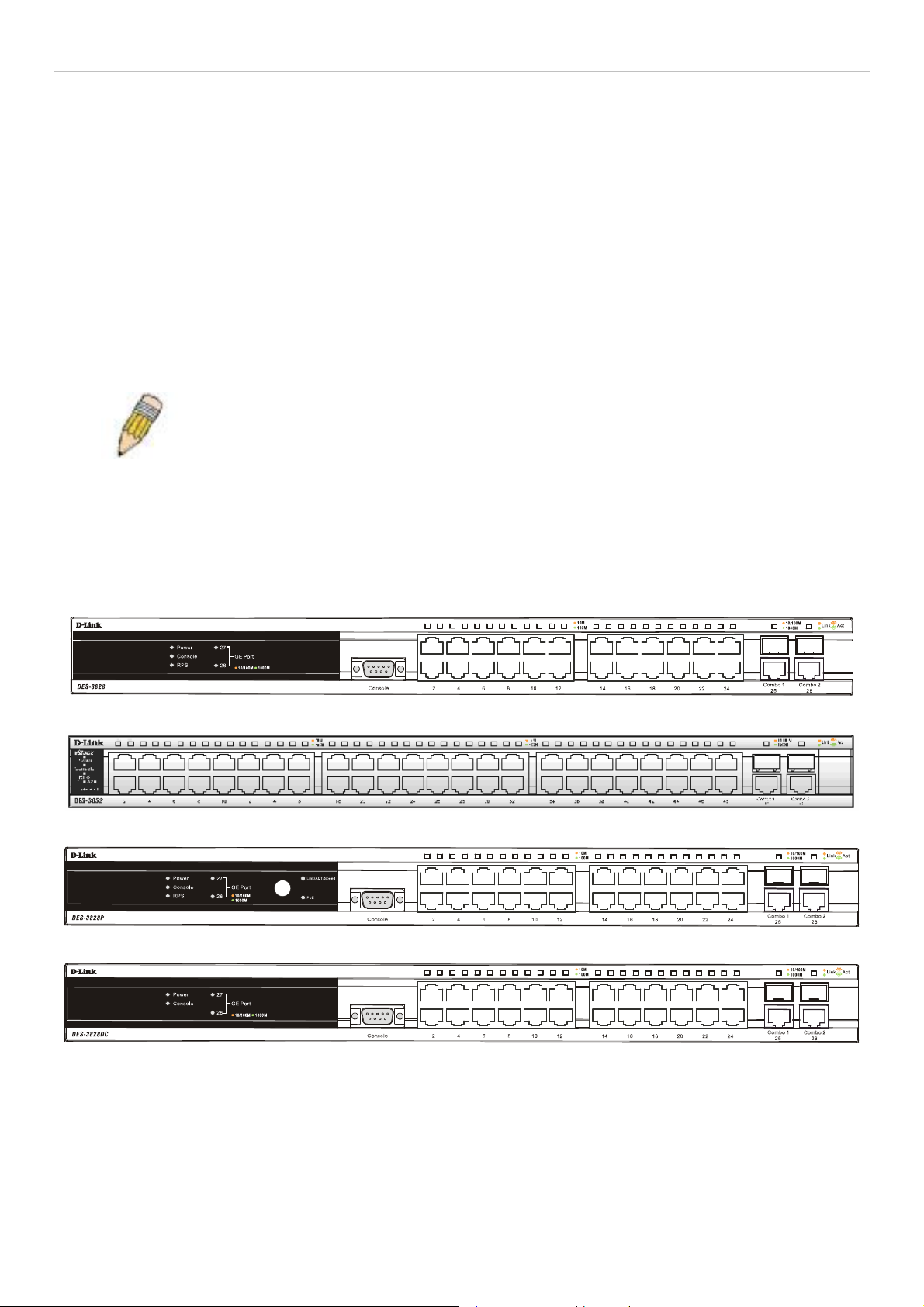
xStack DES-3800 Series Layer 3 Stackable Fast Ethernet Managed Switch
Both SFP ports support the following transceivers:
• DEM-310GT (1000BASE-LX)
• DEM-311GT (1000BASE-SX)
• DEM-314GT (1000BASE-LH)
• DEM-315GT (1000BASE-ZX)
The Switch provides two 1000 BASE-T ports on the rear panel. Both 1000BASE-T ports comply with the following standards:
• IEEE 802.3
• IEEE 802.3u
• IEEE 802.3ab
• Support Full-Duplex operations
• IEEE 802.3x Flow Control support for Full-Duplex mode
NOTE: The SFP combo ports on the Switch cannot be used simultaneously with the
corresponding 1000BASE-T ports. If both ports are in use at the same time (ex. port 25 of
the SFP and port 25 of the 1000BASE-T), the SFP ports will take priority over the combo
ports and render the 1000BASE-T ports inoperable.
Front-Panel Components
The front panel of the Switch provides twenty-four 10/100BAS E-TX ports for the DES-3 828, DES-3828P an d DES-3828DC, and
forty-eight 10/100BASE-TX ports for the DES-3852, two 1000 Base-T/SFP combo ports, and an RS-232 console port (for the
DES-3828, DES-3828P and DES-3828DC only). The DES-3828P also includ es a Mode Select button for ch anging the mod e from
Link/Act/State to PoE.
Figure 1- 1. Front Panel of the DES-3828
Figure 1- 2. Front Panel of the DES-3852
Figure 1- 3. Front Panel of the DES-3828P
Figure 1- 4. Front Panel of the DES-3828DC
DES-3828P LEDs
LED indicators display the status of the Switch and the network. The front panel of DES-3828P has LED indicators for power,
console, RPS, 27GE (rear port), 28 GE (rear port), Link/Act/Speed, PoE, for each of the twenty-four 10/100 Mbps Ethernet ports,
and for the two 1000BASE-T/SFP ports.
2
Page 19
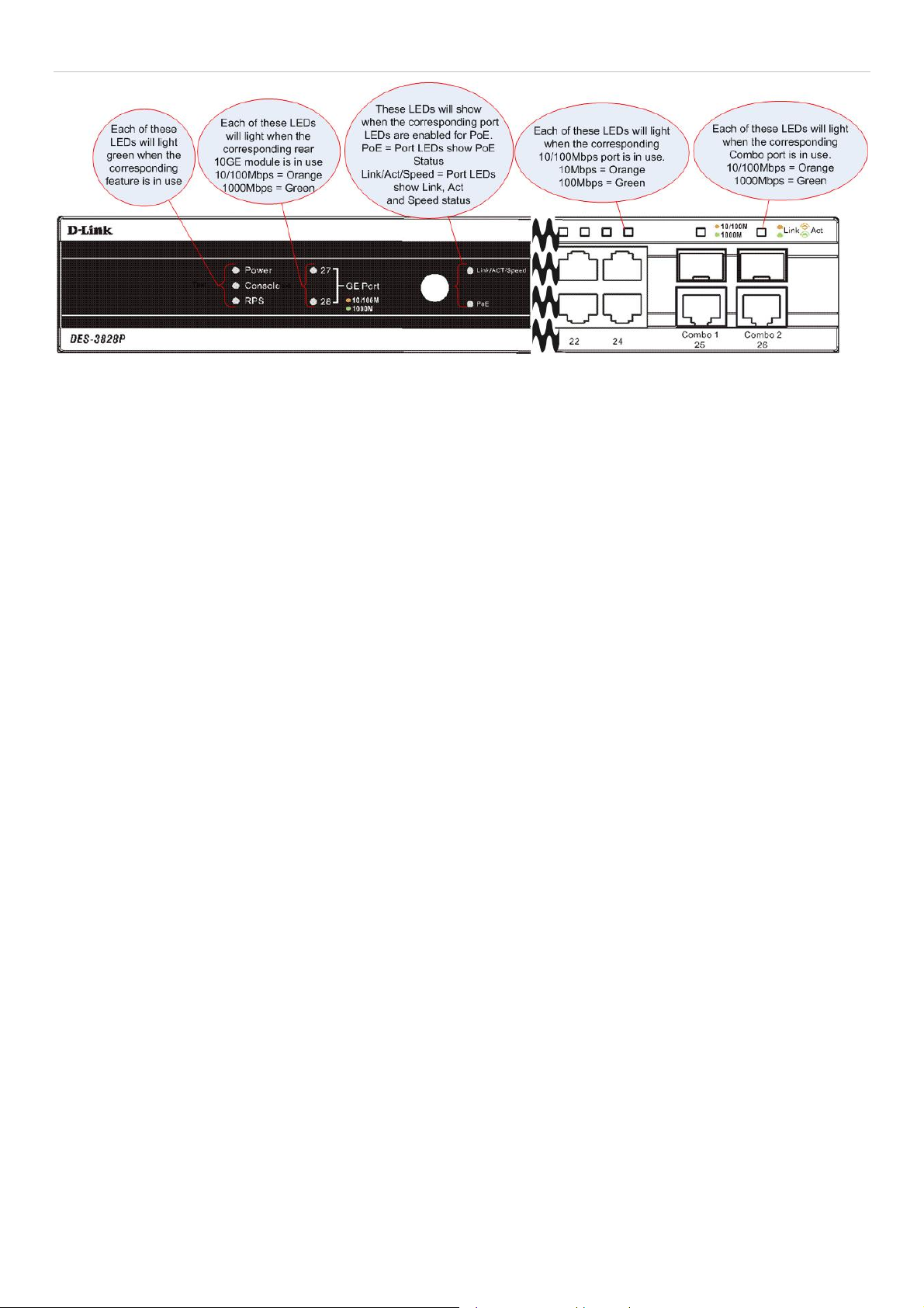
xStack DES-3800 Series Layer 3 Stackable Fast Ethernet Managed Switch
Figure 1- 5. Front Panel View of the DES-3828P
3
Page 20

xStack DES-3800 Series Layer 3 Stackable Fast Ethernet Managed Switch
DES-3828/DES-3828DC LEDs
The front panel of DES-3828/DES-3828DC has LED indicators for power, console, RPS (DES-3 828 only), 27GE (rear port), 28
GE (rear port), for each of the twenty-four 10/100 Mbps Ethernet ports, and for the two 1000BASE-T/SFP ports.
Figure 1- 6. Front Panel View of the DES-3828DC
DES-3852 LEDs
The front panel of DES-3852 has LED indicators for power, console, RPS, port 49 GE, port 50 GE, port 51 GE (rear port), port 52
GE (rear port), for each of the forty-eight 10/100 Mbps Ethernet ports, and for the two 1000BASE-T/SFP ports.
Figure 1- 7. LED Indicators for the DES-3852
The following table describes the LEDs for DES-3828/DES-3828P/DES-3828DC/DES-3852:
LED Description
Power
Console Solid Green – Switch is being logged in to via the out-of-band/local console management
Off – Power Off
Solid Green – Power On
through the RS-232 console port
Blinking Green – POST is in progress
4
Page 21

xStack DES-3800 Series Layer 3 Stackable Fast Ethernet Managed Switch
RPS (excluding DES3828DC)
Ports 27, 28 GE
(DES-3828/DES3828P/DES-3828DC)
Ports 51, 52 GE
(DES-3852)
Link/Act/Speed and
PoE (DES-3828P
only)
Off – RPS off
Solid green – RPS in use
Ports 27 and 28 (51 and 52) represent the 1000BASE-T ports located on the rear panel of
the Switch. These port LEDs will light two different colors for 100Mbps and 1000Mbps:
• Solid Green – Link for 1000Mbps
• Blinking Green – Activity for 1000Mbps
• Solid Amber – Link for 100Mbps
• Blinking Amber – Activity for 100Mbps
• Off – Link down
To change the LED mode from Link/Act/Speed to PoE and vice versa, press the LED Mode
Select Button. The Link/Act/Speed LED will light solid green when selected and will shut off
when PoE is selected. Likewise, when Link/Act/Speed is selected, the PoE LED shuts off
and the Link/Act/Speed LED lights solid green.
When this LED is in PoE mode, the corresponding port LED denote different meanings:
• Solid Green – Power is being used by a device connected to that port.
• Blinking Amber – There is a power error occurring on this port.
• Off – Power is not currently being fed through this port.
Ports 1-24 (1-48) One row of LEDs for each port is located above the ports on the front panel. The first LED is
for the top port and the second one is for the bottom ports. These port LEDs display the
following information:
For Link/Act/Speed Mode:
• Solid Green – Link for 100Mbps
• Blinking Green – Activity for 100Mbps
• Solid Amber – Link for 10Mbps
• Blinking Amber – Activity for 10Mbps
• Off – Link down
For PoE Mode: (DES-3828P only)
• Solid Green – Power feeding (802.3af-compliant PD was detected, legacy PD
detected)
• Blinking Amber – A blinking amber LED may signify any of the following: PoE port
ERROR (non-standard PD connected, Under load state according to 802.3af
(current is below I min), Overload state according to 802.3af (current is above I cut),
hardware problems preventing port operation, power budget exceeded, short
condition was detected at a port delivering power, temperature overload at the port,
succession of Underload and Overload states caused port shutdown (may be
caused by a PD’s DC/DC fault)...etc.)
• Off – No power feeding (no PD detected, or no connection)
Ports 25, 26 combo
GE (DES-3828/DES3828P/DES-3828DC)
Ports 49, 50 combo
GE (DES-3852)
Ports 25 and 26 (49, 50) represent the 1000BASE-T/SFP ports located on the front panel of
the Switch. These port LEDs will display the following information:
• Solid Green – Link for 1000Mbps
• Blinking Green – Activity for 1000Mbps
• Solid Amber – Link for 100Mbps
• Blinking Amber – Activity for 100Mbps
• Off – Link down
5
Page 22
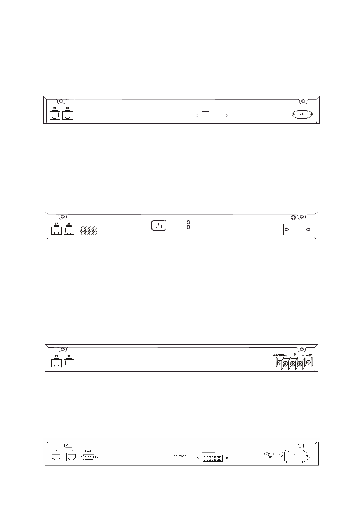
xStack DES-3800 Series Layer 3 Stackable Fast Ethernet Managed Switch
Rear Panel Description
The rear panels of DES-3828, DES-3828DC, DES-3828P and DES-3852 are described separately below.
DES-3828
The rear panel of DES-3828 contains ports 27 and 28, (1000 BASE-TX), an AC power connector, and an outlet for an optional
external RPS.
Figure 1- 8. Rear panel view of the DES-3828
For details on ports 27 and 28, see the “Ports” description above. The rear panel includes an outlet for an optional external
redundant power supply. When power fails, the optional extern al RPS will take ov er all the power immediately an d au tomatically.
The AC power connector is a standard three-pronged connector th at supports the power cord. Plug-in the female conn ector of the
provided power cord into this socket, and the male sid e of the co rd into a power outlet. The Switch automatically adj usts its power
setting to any supply voltage in the range from 100 ~ 240 VAC at 50 ~ 60 Hz.
DES-3828P
The rear panel of DES-3828P contain s ports 27 and 28, (1000BASE- TX), a heat vent, an AC pow er connector, and an outlet for
an optional external RPS.
Figure 1- 9. Rear Panel view of DES-3828P
For details on ports 27 and 28, see the “Ports” d escription above. The rear panel includes a heat vent for the system fan. The
system fan is used to dissipate heat. Do not block this opening, and leave at least 6 inches of space at the rear of the Switch for
proper ventilation. Be reminded that without proper heat dissipation and air circulation, system components might overheat, which
could lead to system failure. The rear panel also includes an outlet for an optional external redundant power supply. When power
fails, the optional external RPS will take over all the power immediately and automatically. The AC power connector is a standard
three-pronged connector that supports the power cord. Plug-in th e female connector of the provided power cord into this sock et,
and the male side of the cord into a power outlet. The Switch automatically adjusts its power settin g to any supply voltage in the
range from 100 ~ 240 VAC at 50 ~ 60 Hz. The maximum output capacity for PoE is 370W. The def ault power feed for PoE is set
at 15.4W per port, but can be set from 1-16.8W per port. See the PoE Configuration in Section 6 for instructions on how to change
this setting.
DES-3828DC
Figure 1- 10. Rear panel view of DES-3828DC
The rear panel of the DC power version of the Switch includes ports 27 and 28, (1000BASE-TX), and an opening designed to
accommodate the DC power wiring assembly. See the installation instructions in Section 2 for details.
DES-3852
The rear panel of the DES-3852 contains ports 51 and 52, (1 000BASE-TX) , an AC power connector, an RS-232 conso le port and
an outlet for an optional external RPS.
Figure 1- 11. Rear Panel of the DES-3852
6
Page 23
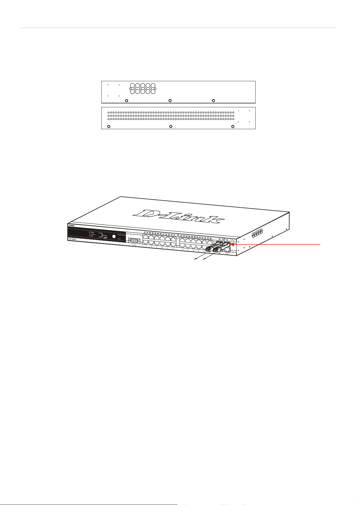
xStack DES-3800 Series Layer 3 Stackable Fast Ethernet Managed Switch
Side Panel Description
The right-hand side panel of the Switch contains a system fan and ventilation along the entire right side. The left hand panel
includes a system fan and a heat vent. The system fans are used to dissipate heat. Do not block these openings on either side of the
Switch. Leave at least 6 inches of space at the rear and sides of the Switch for proper ventilation. Be reminded that without proper
heat dissipation and air circulation, system components might overheat, which could lead to system failure.
Figure 1- 12. Side Panels
Gigabit Ports
In addition to the twenty-four (forty-eight for DES-3852) 10/100 Mbps ports, the Switch features two 1000BASE-T/SFP Gigabit
Ethernet Combo ports on the front panel, and two 1000BASE-T copper ports on the rear panel. The diagra ms below show Gigabit
ports 25 and 26 (49 and 50) on the far right of the front panel. Gigabit ports 27 and 28 (51 and 52) are on the far left of the rear
panel. Please note that PoE is not supported for any Gigabit Ethernet ports.
Figure 1- 13. Front Panel Mini-GBIC ports
7
Page 24

xStack DES-3800 Series Layer 3 Stackable Fast Ethernet Managed Switch
SECTION 2
Installation
Package Contents
Before You Connect to the Network
Installing the Switch without the Rack
Rack Installation
Power On
Connecting DC Power to DES-3828DC
RPS Installation
Package Contents
Open the shipping carton of the Switch and carefully unpack its contents. The carton should contain the following items:
• One Stand-alone Switch
• One AC power cord (excluding DES-3828DC)
• This Manual on CD
• Mounting kit (two brackets and screws)
• Four rubber feet with adhesive backing
• RS-232 console cable
If any item is missing or damaged, please contact your local D-Link Reseller for replacement.
Before You Connect to the Network
The site where users install the Switch may greatly affect its performance. Please follow these guidelines for setting up the Switch.
• Install the Switch on a sturdy, level surface that can support at least 4.24kg (9.35lbs) of weight for DES-3828/DES-
3828DC/DES-3852, or 6.02kg (13.27lbs) for DES-3828P. Do not place heavy objects on the Switch.
• The power outlet should be within 1.82 m e t e rs (6 feet) of the Swit ch .
• Visually inspect the power cord and see that it is fully secured to the AC/DC power port.
• Make sure that there is proper heat dissipation from and adequate ventilation around the Switch. Leave at least 10 cm (4
inches) of space at the front and rear of the Switch for ventilation.
• Install the Switch in a fairly cool and dry place for the acceptable temperature and humidity operating ranges.
• Install the Switch in a site free from strong electromagnetic field generators (such as motors), vibration, dust, and direct
exposure to sunlight.
• When installing the Switch on a level surface, attach the rubber feet to the bottom of the device. The rubber feet cushion
the Switch, protect the casing from scratches and prevent it from scratching other surfaces.
8
Page 25
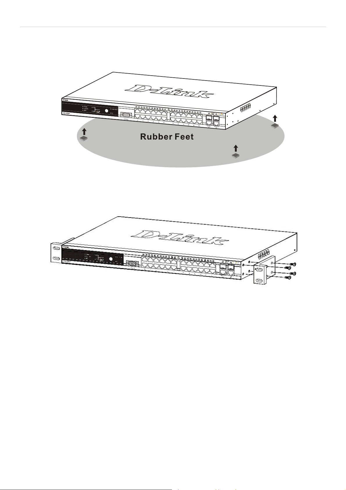
xStack DES-3800 Series Layer 3 Stackable Fast Ethernet Managed Switch
Installing the Switch without the Rack
When installing the Switch on a desktop or shelf, the rubber feet included with the Switch should first be attached. Attach the se
cushioning feet on the bottom at each corner of the device. Allow enough ventilation space between the Switch and any other
objects in the vicinity.
Figure 2 - 1. Prepare Switch for installation on a desktop or shelf
Installing the Switch in a Rack
The Switch can be mounted in a standard 19" rack. Use the following diagrams to guide you.
Figure 2 - 2. Fasten mounting brackets to Switch
Fasten the mounting brackets to the Switch using the screws provided. With the brackets attached securely, users can mount the
Switch in a standard rack as shown in Figure 2-3 below.
9
Page 26
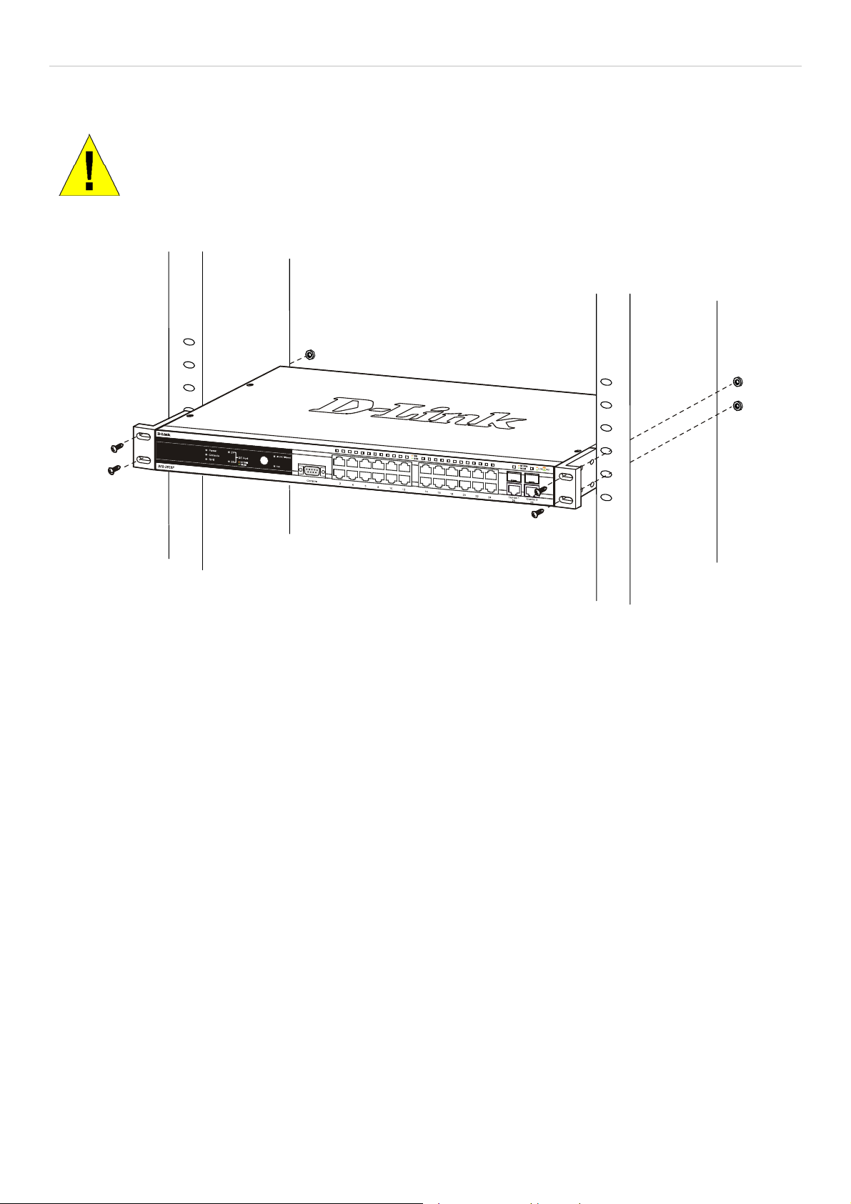
xStack DES-3800 Series Layer 3 Stackable Fast Ethernet Managed Switch
Mounting the Switch in a Standard 19" Rack
CAUTION: Installing systems in a rack without the front and side stabilizers installed could cause the
rack to tip over, potentially resulting in bodily injury under certain circumstances. Therefore, always
install the stabilizers before installing components in the rack. After installing components in a rack, do
not pull more than one component out of the rack on its slide assemblies at one time. The weight of
more than one extended component could cause the rack to tip over and may result in injury.
Figure 2 - 3. Installing Switch in a rack
10
Page 27
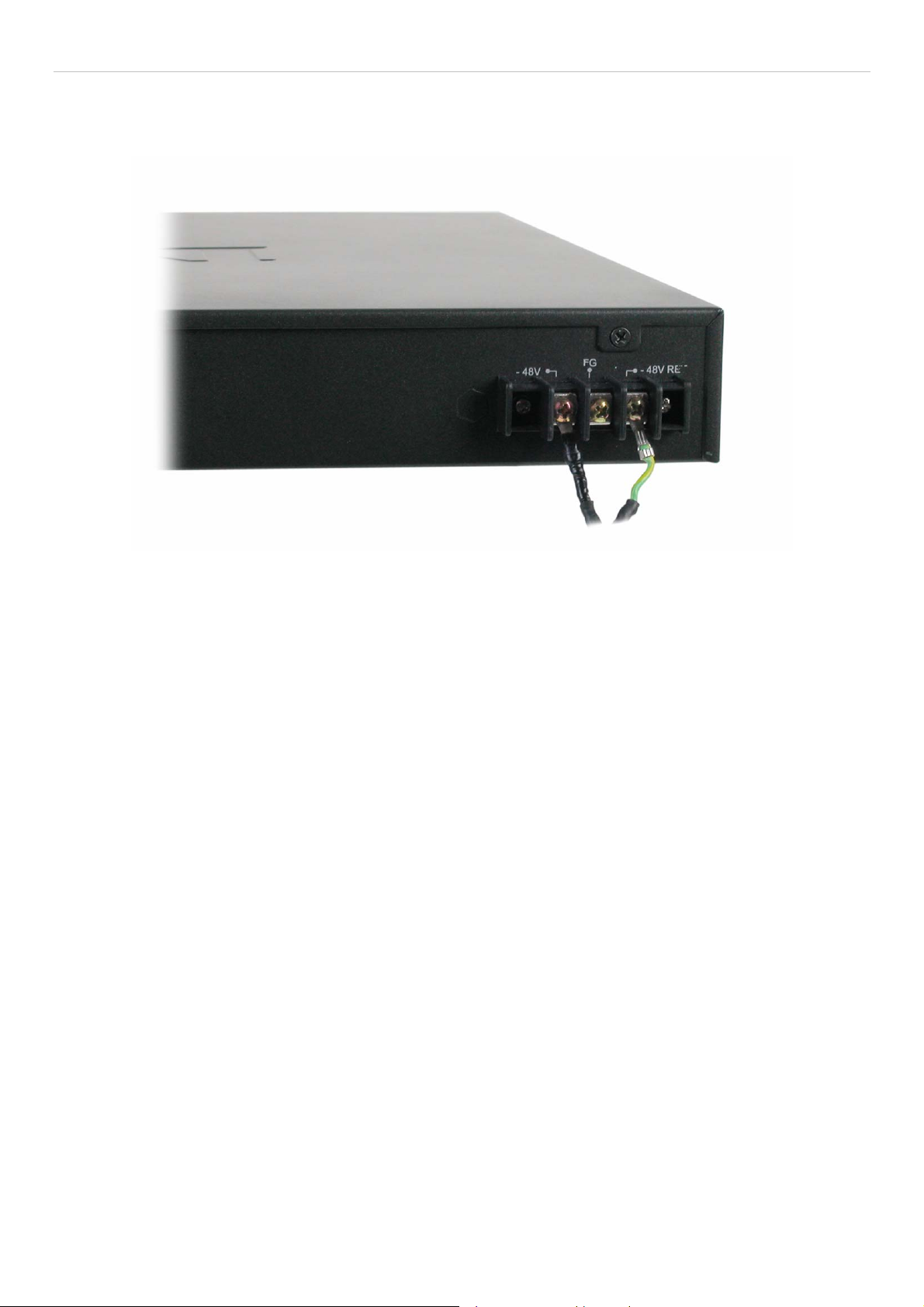
xStack DES-3800 Series Layer 3 Stackable Fast Ethernet Managed Switch
Connecting DC Power to the DES-3828DC
Follow the instructions below to connect the DC power supply of the DES-3828DC to the DC power source.
Figure 2 - 5. Power connections attached to contacts after assembly
1. Firmly attach the DC power to the negative and positive contacts on the wiring assembly.
• The negative pole (-) connects to the -48V contact.
• The positive pole (+) connects to the -48V Return contact.
• If available, an earth ground may be connected to the center contact post.
2. Tighten the contact screws to secure the connection.
12
Page 28
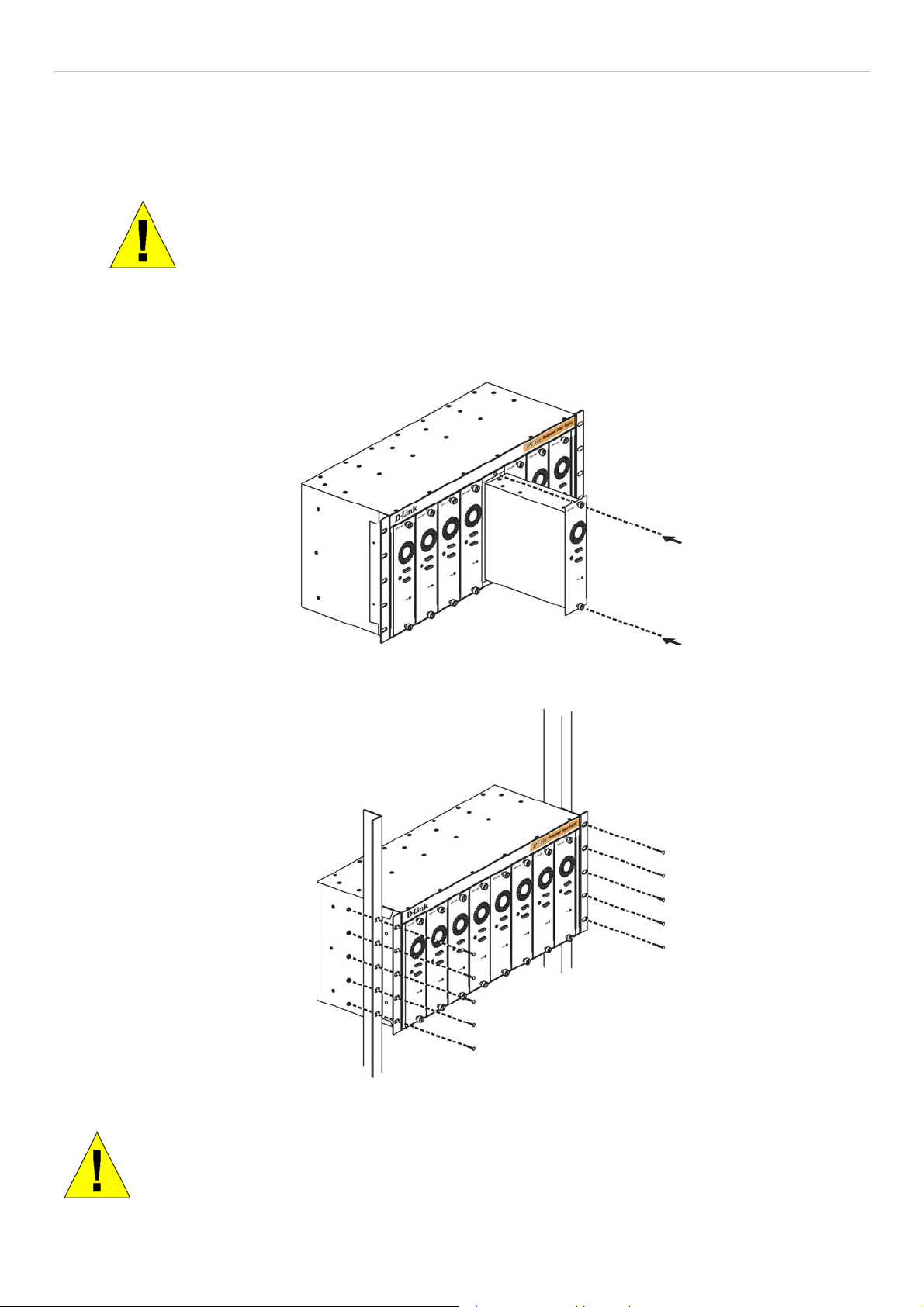
xStack DES-3800 Series Layer 3 Stackable Fast Ethernet Managed Switch
RPS Installation
Follow the instructions below to connect an RPS power supply to the Switch (DPS-200 to DES-3828/DES-3852 or DPS-600 to
DES-3828P). The DPS-200 is a redundant power-supply unit designed to conform to the voltage requirements of the switches
being supported. DPS-200 can be installed into DPS-900, or DPS-800.
CAUTION: The AC power cord for the Switch should be disconnected before proceeding
with installation of the DPS-200.
DPS-900
The DPS-900 is a standard-size rack mount (5 standard units in height) designed to hold up to eight DPS-200 redundant power
supplies.
Figure 2 - 6. Installing the DPS-200 into the DPS-900
The RPS can be mounted in a standard 19" rack. Use the following diagram to guide you.
Figure 2 - 7. Installing the DPS-900 into the equipment rack
CAUTION: Installing systems in a rack without the front and side stabilizers installed could cause the
rack to tip over, potentially resulting in bodily injury under certain circumstances. Therefore, always
install the stabilizers before installing components in the rack. After installing components in a rack, do
not pull more than one component out of the rack on its slide assemblies at one time. The weight of
more than one extended component could cause the rack to tip over and may result in injury.
13
Page 29
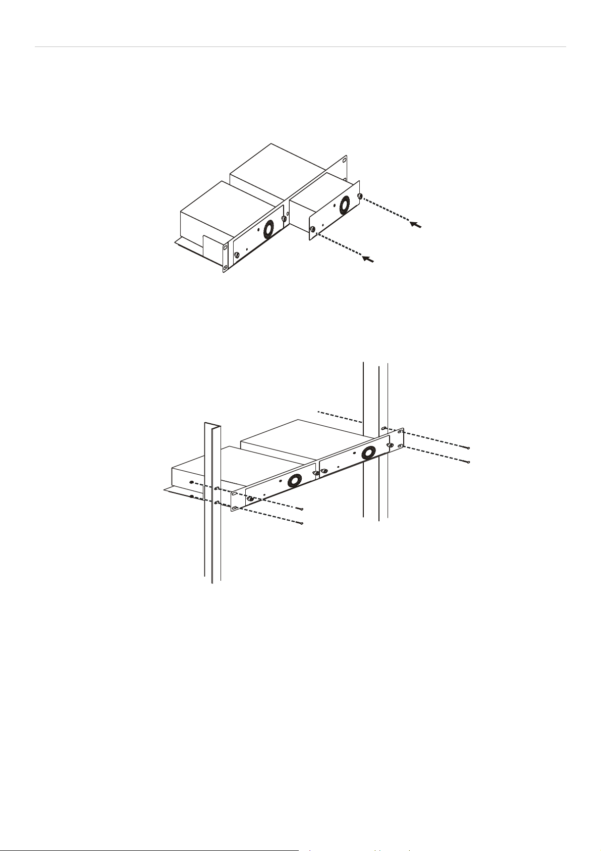
xStack DES-3800 Series Layer 3 Stackable Fast Ethernet Managed Switch
DPS-800
The DPS-800 is a standard-size rack mount (1 standard unit in height) designed to hold up to two DPS-200 redundant power
supplies.
Figure 2 - 8. Install DPS-200 in DPS-800
The RPS can be mounted in a standard 19" rack. Use the following diagram to guide you.
Figure 2 - 9. Install DPS-800 in an Equipment Rack
14
Page 30
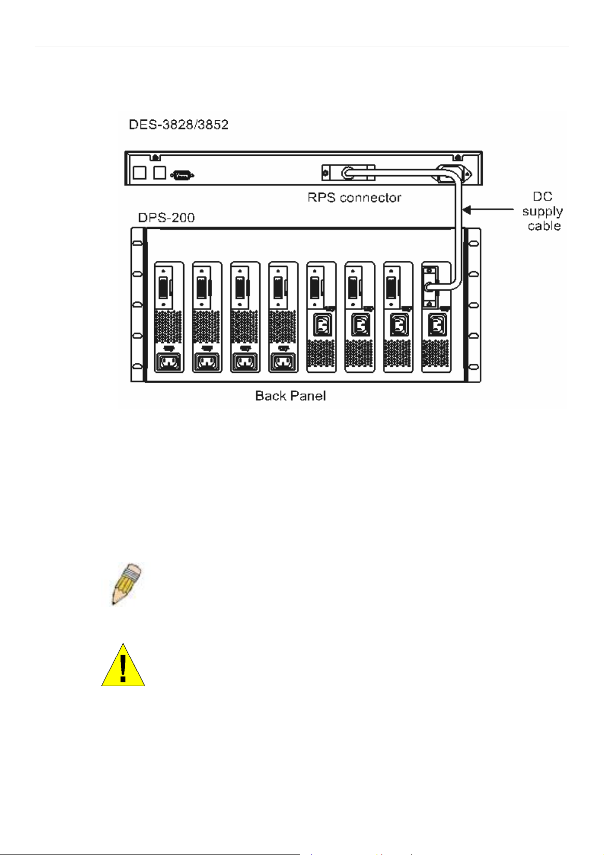
xStack DES-3800 Series Layer 3 Stackable Fast Ethernet Managed Switch
Connect to RPS
The DPS-200 is connected to the Master Switch using a 14-pin DC power cable. A standard, three-pronged AC power cable
connects the redundant power supply to the main power source.
Figure 2 - 10. The DES-3828 with the DPS-200 chassis RPS
1. Insert one end of the 14-pin DC power cable into the receptacle on th e Switch and the other end into the redundant power
supply.
2. Using a standard AC power cable, connect the redundant power supply to the main AC power source. A green LED on the
front of the DPS-200 will glow to indicate a successful connection.
3. Re-connect the switch to the AC power source. On certain switches, such as the DES-3828, an LED indicator will show that a
redundant power supply is now in operation.
4. No change in switch configuration is necessary for this installation.
NOTE: See the DPS-200 documentation for more information.
CAUTION: Do not use the Switch with any redundant power system other
than the DPS-200 or DPS-600.
15
Page 31

xStack DES-3800 Series Layer 3 Stackable Fast Ethernet Managed Switch
DPS-600
DES-3828P also supports the DPS-600 ex ternal redundant power supply.
DES-3828P
DPS-600
Figure 2 - 11. DES-3828P with the DPS-600 External Redundant Rower Supply
16
Page 32

xStack DES-3800 Series Layer 3 Stackable Fast Ethernet Managed Switch
Section 3
Connecting the Switch
Switch to End Node
Switch to Hub or Switch
Connecting to Network Backbone or Server
NOTE: All 24 high-performance NWay Ethernet ports can support both
MDI-II and MDI-X connections.
Switch to End Node
End nodes include PCs outfitted with a 10, 100 or 1000 Mbps RJ 45 Ethernet/Fast Ethernet Network Interface Card (NIC) and
most routers. An end node can be connected to the Switch via a twisted-pair Category 3, 4, or 5 UTP/STP cable. The end node
should be connected to any of the ports of the Switch.
Figure 3- 1. Switch connected to an end node
The Link/Act LEDs for each UTP port will light green or amber when the link is valid. A blinking LED indicates packet activity
on that port.
17
Page 33

xStack DES-3800 Series Layer 3 Stackable Fast Ethernet Managed Switch
Switch to Hub or Switch
These connections can be accomplished in a number of ways using a normal cable.
• A 10BASE-T hub or switch can be connected to the Switch via a twisted-pair Category 3, 4 or 5 UTP/STP cable.
• A 100BASE-TX hub or switch can be connected to the Switch via a twisted-pair Category 5 UTP/STP cable.
• A 1000BASE-T switch can be connected to the Switch via a twisted pair Category 5e UTP/STP cable.
• A switch supporting a fiber-optic uplink can be connected to the Switch’s SFP ports via fiber-optic cabling.
• The Switch can be changed to PoE mode using the Mode Select button. When in PoE Mode, the DES-3828P will work
with all D-Link 802.3af capable devices. The Switch also works in PoE mode with all non-802.3af capable D-Link AP,
IP Cam and IP phone equipment via DWL-P50.
Figure 3- 2. Switch connected to a normal (non-Uplink) port on a hub or switch using a straight or crossover
cable
NOTICE: When the SFP transceiver acquires a link, the associated
integrated 10/100/1000BASE-T port is disabled.
18
Page 34

xStack DES-3800 Series Layer 3 Stackable Fast Ethernet Managed Switch
Connecting To Network Backbone or Server
The two Mini-GBIC combo ports are ideal for unlinking to a network backbone or server. The copper ports operate at a speed of
1000, 100 or 10Mbps in full duplex mode. The fiber optic ports can operate at 1000Mbps in full duplex mode. Connections to the
Gigabit Ethernet ports are made using fiber optic cable or Category 5 copper cable, depending on the type of port. A valid
connection is indicated when the Link LED is lit.
Figure 3- 3. Uplink Connection to a server, PC or switch stack.
19
Page 35

xStack DES-3800 Series Layer 3 Stackable Fast Ethernet Managed Switch
Section 4
Introduction to Switch Management
Management Options
Web-based Management Interface
SNMP-Based Management
Managing User Accounts
Command Line Console Interface through the Serial Port
Connecting the Console Port (RS-232 DCE)
First Time Connecting to the Switch
Password Protection
SNMP Settings
IP Address Assignment
Management Options
This system may be managed out-of-band through the console port on the front panel or in-band using Telnet. The user may also
choose the web-based management, accessible through a web browser.
Web-based Management Interface
After you have successfully installed the Switch, you can configure the Switch, monitor the LED panel, and display statistics
graphically using a web browser, such as Netscape Navigator (version 6.2 and higher) or Microsoft® Internet Explorer (version
5.0).
SNMP-Based Management
You can manage the Switch with an SNMP-compatible console program. The Switch supports SNMP version 1.0, version 2.0 and
version 3.0. The SNMP agent decodes the incoming SNMP messages and responds to requests with MIB objects stored in the
database. The SNMP agent updates the MIB objects to generate statistics and counters.
Connecting the Console Port (RS-232 DCE)
The Switch provides an RS-232 serial port that enables a connection to a computer or terminal for monitoring and configuring the
Switch. This port is a female DB-9 connector, implemented as a Data Communication Equipment (DCE) connection.
To use the console port, you need the following equipment:
• A terminal or a computer with both a serial port and the ability to emulate a terminal.
• A null modem straight-through RS-232 cable with a female DB-9 connector for the console port on the Switch.
To connect a terminal to the console port:
1. Connect the female connector of the RS-232 cable directly to the console port on the Switch, and tighten the captive
retaining screws.
2. Connect the other end of the cable to a terminal or to the serial connector of a computer running terminal emulation
software. Set the terminal emulation software as follows:
3. Select the appropriate serial port (COM port 1 or COM port 2).
4. Set the data rate to 9600 baud.
5. Set the data format to 8 data bits, 1 stop bit, and no parity.
6. Set flow control to none.
20
Page 36

xStack DES-3800 Series Layer 3 Stackable Fast Ethernet Managed Switch
7. Under Properties, select VT100 for Emulation mode.
8. Select Terminal keys for Function, Arrow, and Ctrl keys. Ensure that you select Terminal keys (not Windows keys).
NOTE: When you use HyperTerminal with the Microsoft® Windows® 2000 operating system, ensure that you have Windows 2000 Service Pack 2 or later installed. Windows 2000
Service Pack 2 allows you to use arrow keys in HyperTerminal's VT100 emulation. See
www.microsoft.com for information on Windows 2000 service packs.
9. After you have correctly set up the terminal, plug the power cable into the power receptacle on the back of the Switch.
The boot sequence appears in the terminal.
10. After the boot sequence completes, the console login screen displays.
11. If you have not logged into the command line interface (CLI) program, press the Enter key at the User name and
password prompts. There is no default user name and password for the Switch. The administrator must first create user
names and passwords. If user accounts have been previously set, log in and continue to configure the Switch.
12. Enter the commands to complete your desired tasks. Many commands require administrator-level access privileges. Read
the next section for more information on setting up user accounts. See the xStack DES-3800 Series CLI Manual on the
documentation CD for a list of all commands and additional information on using the CLI.
13. When all tasks have been completed, exit the session with the logout command or close the emulator program.
14. Make sure the terminal or PC you are using to make this connection is configured to match these settings.
If users have problems making this connection on a PC, make sure the emulation is set to VT-100. Set the emulation by clicking
on the File menu in you HyperTerminal window, clicking on Properties in the drop-down menu, and then clicking the Settings
tab. This is where you will find the Emulation options. If users still do not see anything, try rebooting the Switch by
disconnecting its power supply.
Once connected to the console, the screen below will appear. This is where the user will enter commands to perform all the
available management functions. The Switch will prompt the user to enter a user name and a password. Upon the initial
connection, there is no user name or password and therefore just press enter twice to access the command line interface.
DES-3828 Fast Ethernet Switch Command Line Interface
Firmware: Build 4.50.B10
Copyright(c) 2008 D-Link Corporation. All rights reserved.
UserName:
Figure 4- 1. Initial screen after first connection
NOTICE: In case of lost passwords or password corruption, please refer to the
D-Link website and the White Paper entitled “Password Recovery Procedure”,
which will guide you through the steps necessary to resolve this issue.
21
Page 37

xStack DES-3800 Series Layer 3 Stackable Fast Ethernet Managed Switch
First Time Connecting to the Switch
The Switch supports user-based security that can allow prevention of unauthorized users from accessing the Switch or changing
its settings. This section tells how to log onto the Switch.
NOTE: The passwords used to access the Switch are case-sensitive; therefore, "S" is
not the same as "s."
Upon initial connection to the Switch, users will be presented with the first login screen.
NOTE: Press Ctrl+R to refresh the screen. This command can be used at any time to
force the console program in the Switch to refresh the console screen.
Press Enter in both the Username and Password fields. You will be given access to the command prompt DES-3828:admin#
shown below:
There is no initial username or password. Leave the Username and Password fields blank.
DES-3828 Fast Ethernet Switch Command Line Interface
Firmware: Build 4.50.B10
Copyright(c) 2008 D-Link Corporation. All rights reserved.
UserName:
Password:
DES-3828:admin#
Figure 4- 2. Command Prompt
NOTE: The first user automatically gets Administrator level privileges. It is recommended to
create at least one Admin-level user account for the Switch.
22
Page 38

xStack DES-3800 Series Layer 3 Stackable Fast Ethernet Managed Switch
Password Protection
The Switch does not have a default user name and password. One of the first tasks when settings up the Switch is to create user
accounts. If logging in using a predefined administrator-level user name, users will have privileged access to the Switch's
management software.
After the initial login, define new passwords for both default user names to prevent unauthorized access to the Switch, and record
the passwords for future reference.
To create an administrator-level account for the Switch, follow these steps:
• At the CLI login prompt, enter create account admin followed by the <user name> and press the Enter key.
• Users will be asked to provide a password. Type the <password> used for the administrator account being created and
press the Enter key.
• Users will then be prompted to enter the same password again to verify it. Type the same password and press the Enter
key.
• Successful creation of the new administrator account will be verified by a Success m essage.
NOTE: Passwords are case sensitive. User names and passwords can be
up to 15 characters in length.
The sample below illustrates a successful creation of a new administrator-level account with the user name "newmanager".
DES-3828:admin#create account admin newmanager
Command: create account admin newmanager
Enter a case-sensitive new password:********
Enter the new password again for confirmation:********
Success.
DES-3828:admin#
NOTICE: CLI configuration commands only modify the running configuration file
and are not saved when the Switch is rebooted. To save all configuration
changes in nonvolatile storage, users must use the save command to copy the
running configuration file to the startup configuration.
NOTICE: In case of lost passwords or password corruption, please refer to the
D-Link website and the White Paper entitled “Password Recovery Procedure”,
which will guide you through the steps necessary to resolve this issue.
23
Page 39

xStack DES-3800 Series Layer 3 Stackable Fast Ethernet Managed Switch
SNMP Settings
Simple Network Management Protocol (SNMP) is an OSI Layer 7 (Application Layer) designed specifically for managing and
monitoring network devices. SNMP enables network management stations to read and modify the settings of gateways, routers,
switches, and other network devices. Use SNMP to configure system features for proper operation, monitor performance and
detect potential problems in the Switch, switch group or network.
Managed devices that support SNMP include software (referred to as an agent), which runs locally on the device. A defined set of
variables (managed objects) is maintained by the SNMP agent and used to manage the device. These objects are defined in a
Management Information Base (MIB), which provides a standard presentation of the information controlled by the on-board
SNMP agent. SNMP defines both the format of the MIB specifications and the protocol used to access this information over the
network.
The DES-3800 Series supports SNMP versions 1, 2c, and 3. You can specify which version of SNMP you want to use to monitor
and control the Switch. The three versions of SNMP vary in the level of security provided between the management station and
the network device.
In SNMP v.1 and v.2, user authentication is accomplished using 'community strings', which function like passwords. The remote
user SNMP application and the Switch SNMP must use the same community string. SNMP packets from any station that has not
been authenticated are ignored (dropped).
The default community strings for the Switch used for SNMP v.1 and v.2 management access are:
• public - Allows authorized management stations to retrieve MIB objects.
• private - Allows authorized management stations to retrieve and modify MIB objects.
SNMP v.3 uses a more sophisticated authentication process that is separated into two parts. The first part is to maintain a list of
users and their attributes that are allowed to act as SNMP managers. The second part describes what each user on that list can do
as an SNMP manager.
The Switch allows groups of users to be listed and configured with a shared set of privileges. The SNMP version may also be set
for a listed group of SNMP managers. Thus, users may create a group of SNMP managers that are allowed to view read-only
information or receive traps using SNMP v.1 while assigning a higher level of security to another group, granting read/write privileges using SNMP v.3.
Using SNMP v.3 individual users or groups of SNMP managers can be allowed to perform or be restricted from performing
specific SNMP management functions. The functions allowed or restricted are defined using the Object Identifier (OID)
associated with a specific MIB. An additional layer of security is available for SNMP v.3 in that SNMP messages may be
encrypted. To read more about how to configure SNMP v.3 settings for the Switch read the section entitled Management.
Traps
Traps are messages that alert network personnel of events that occur on the Switch. The events can be as serious as a reboot
(someone accidentally turned OFF the Switch), or less serious like a port status change. The Switch generates traps and sends
them to the trap recipient (or network manager). Typical traps include trap messages for Auth entication Failure, Topolog y Chang e
and Broadcast\Multicast Storm.
MIBs
The Switch in the Management Information Base (MIB) stores management and counter information. The Switch uses the
standard MIB-II Management Information Base module. Consequently, values for MIB objects can be retrieved from any SNMPbased network management software. In addition to the standard MIB-II, the Switch also supports its own proprietary enterprise
MIB as an extended Management Information Base. Specifying the MIB Object Identifier may also retrieve the proprietary MIB.
MIB values can be either read-only or read-write.
24
Page 40

xStack DES-3800 Series Layer 3 Stackable Fast Ethernet Managed Switch
IP Address Assignment
Each Switch must be assigned its own IP Address, which is used for communication with an SNMP network manager or other
TCP/IP application (for example BOOTP, TFTP). The Switch's default IP address is 10.90.90.90. You can change the default
Switch IP address to meet the specification of your networking address scheme.
The Switch is also assigned a unique MAC address by the factory. This MAC address cannot be changed, and can be found by
entering the command "show switch" into the command line interface, as shown below.
DES-3828:admin#show switch
Command:show switch
Device Type : DES-3828 Fast-Ethernet Switch
Combo Port Tpye : 1000Base-T + 1000Base-T
MAC Address : 00-01-02-03-04-00
IP Address : 10.53.13.83 (Manual)
VLAN Name : default
Subnet Mask : 255.0.0.0
Default Gateway : 0.0.0.0
Boot PROM Version : Build 0.00.010
Firmware Version : Build 4.50-B10
Hardware Version : 1A2G
Serial Number : N/A
Power Status : Main - Normal, Redundant - Not Present
System Name : D-Link
System Location :
System Contact :
Spanning Tree : Disabled
GVRP : Disabled
IGMP Snooping : Disabled
TELNET : Enabled (TCP 23)
SSH : Disabled
WEB : Enabled (TCP 80)
RMON : Disabled
RIP : Disabled
DCMRP : Disabled
PIN : Disabled
OSPF : Disabled
SNMP : Disabled
CTRL+C ESC q Quit SPACE n Next Page ENTER Next Entry a All
Figure 4- 3. Show switch command
The Switch's MAC address can also be found from the Web management program on the Switch Information (Basic Settings)
window on the Configuration menu.
The IP address for the Switch must be set before it can be managed with the Web-based manager. The Switch IP address can be
automatically set using BOOTP or DHCP protocols, in which case the actual address assigned to the Switch must be known.
25
Page 41

xStack DES-3800 Series Layer 3 Stackable Fast Ethernet Managed Switch
The IP address may be set using the Command Line Interface (CLI) over the console serial port as follows:
Starting at the command line prompt, enter the commands
config ipif System ipaddress xxx.xxx.xxx.xxx/yyy.yyy.yyy.yyy
Where the x's represen t the IP address to be assigned to th e IP interface named System and the y's represent the correspond ing
subnet mask.
Alternatively, users can enter config ipif System ipaddress xxx.xxx.xxx.xxx/z. Where the x's represent the IP address to be
assigned to the IP interface named System and the z represents the corresponding number of subnets in CIDR notation.
The IP interface named System on the Switch can be assigned an IP address and subnet mask, and then be used to connect a
management station to the Switch's Telnet or Web-based management agent.
DES-3828:admin#config ipif System ipaddress 10.53.13.83/255.0.0.0
Command: config ipif System ipaddress 10.53.13.83/8
Note: All configurations on this interface will return to default
setting.
Success.
DES-3828:admin#
Figure 4- 4. Assigning the Switch an IP Address
In the above example, the Switch was assigned an IP address of 10.53.13.83 with a subnet mask of 255.0.0.0. The user may also
use the CIDR form to set the address (10.53.13.83/8). The system message Success indicates that the command was executed
successfully. The Switch can now be configured and managed via Telnet and the CLI or via the Web-based management.
26
Page 42

xStack DES-3800 Series Layer 3 Stackable Fast Ethernet Managed Switch
Web-based Switch Configuration
Introduction
Login to Web manager
Web-Based User Interface
Basic Setup
Reboot
Basic Switch Setup
Network Management
Switch Utilities
Network Monitoring
IGMP Snooping Status
Introduction
Section 5
All software functions of the Switch can be managed, configured and monitored via the embedded web-based (HTML) interface.
The Switch can be managed from remote stations anywhere on the network through a standard browser such as Opera, Netscape
Navigator/Communicator, or Microsoft Internet Explorer. The browser acts as a universal access tool and can communicate
directly with the Switch using the HTTP protocol.
The Web-based management module and the Console program (and Telnet) are different ways to access the same internal
switching software and configure it. Thus, all settings encountered in web-based management are the same as those found in the
console program.
Login to Web Manager
To begin managing the Switch, simply run the browser installed on your computer and point it to the IP address defined for the
device. The URL in the address bar should read something like: h ttp://123.123.123.123, where the numbers 123 represen t the IP
address of the Switch.
NOTE: The Factory default IP address for the Switch is 10.90.90.90.
This opens the management module's user authentication window, as seen below.
Figure 5- 1. Enter Network Password window
27
Page 43

xStack DES-3800 Series Layer 3 Stackable Fast Ethernet Managed Switch
Leave both the User Name field and the Password field blank and click OK. This will open the Web-based user interface. The
Switch management features available in the web-based manager are explained below.
Web-based User Interface
The user interface provides access to various Switch configuration and management screens, allows users to view performance
statistics, and permits graphical monitoring of the system status.
Areas of the User Interface
The figure below shows the user interface. The user interface is divided into three distinct areas as described in the table.
Area 2
Area 1
Area Function
Area 1
Area 2
Select the menu or window to be displayed. The folder icons can be opened to display the hyperlinked menu buttons and subfolders contained within them. Click the D-Link logo to go to the D-Link
website.
Presents a graphical near real-time image of the front panel of the Switch. This area displays the
Switch's ports and expansion modules, showing port activity, duplex mode, or flow control, depending
on the specified mode.
Various areas of the graphic can be selected for performing management functions, including port
configuration.
Area 3
Figure 5- 2. Main Web-Manager page
Area 3
Presents switch information based on selection and the entry of configuration data.
NOTICE: Any changes made to the Switch configuration during the current session must be
saved in the Save Changes web menu (explained below) or use the command line interface
(CLI) command save.
28
Page 44

xStack DES-3800 Series Layer 3 Stackable Fast Ethernet Managed Switch
Web Pages
When users connect to the management mode of the Switch with a web browser, a login window is displayed. Enter a user name
and password to access the Switch's management mode.
Below is a list and description of the main folders available in the web interface:
Administration – Contains windows concerning Device Information, IP Address, Port Configuration, PoE Configuration (for the
DES-3828P), User Accounts, Port Mirroring, System Log Settings, System Severity Settings, SNTP Settings, MAC Notification
Settings, TFTP Services, Multiple Image Services, Dual Configurations Services, Ping Test, SNMP Manager, and Single IP
Management Settings.
Layer 2 Features – Contains windows concerning VLAN, Trunking, IGMP Snooping, Spanning Tree and Forwarding.
Layer 3 Features – Contains windows concerning IP Interfaces Settings, MD5 Key Settings, Route Redistribution Settings,
Static/Default Route Settings, Route Preference Settings, Static ARP Settings, RIP, OSPF, DHCP/BOOTP Relay, DNS Relay,
VRRP, and IP Multicast Routing Settings .
QoS – Contains windows concerning Bandwidth Control, QoS Scheduling Mechanism, QoS Output Scheduling, 802.1P Default
Priority, 802.1P User Priority and WRED Settings.
ACL – Contains the window for the Access Profile Table and CPU Interface Filtering.
Security – Contains windows for Traffic Control, Port Security, Port Lock Entries, 802.1x, Trusted Host, Access Authentication
Control, Traffic Segmentation, SSL, SSH, IP-MAC Binding, Limited IP Multicast Range, Web-based Access Control, MACbased Access Control and Safeguard Engine.
Monitoring – Contains windows for Device Status, CPU Utilizatio n, Safeguard Engine Status, Port Utilization, Packets, Errors,
Packet Size, Browse Router Port, Port Access Control, MAC Address Table, IP Address Table, Browse Routing Table, Browse
ARP Table, Browse IP Multicast Forwarding Table, IGMP Snooping Group, IGMP Snooping Forwarding, Browse IGMP Group
Table, DVMRP Monitor, PIM Monitor, OSPF Monitor, Browse PoE Status, Browse WRED Settings and Switch Log.
NOTE: Be sure to configure the user name and password in the User
Accounts menu before connecting the Switch to the greater network.
29
Page 45

xStack DES-3800 Series Layer 3 Stackable Fast Ethernet Managed Switch
Administration
Device Information
IP Address
Port Configuration
PoE Configuration
User Accounts
Port Mirroring
System Log Settings
System Severity Settings
SNTP Settings
MAC Notification Settings
TFTP Services
Section 6
Multiple Image Services
Dual Configurations Services
Ping Test
SNMP Manager
Single IP Management Setting
Packet to CPU Settings
30
Page 46

xStack DES-3800 Series Layer 3 Stackable Fast Ethernet Managed Switch
Device Information
The Device Information window contains the main
settings for all major functions for the Switch and appears
automatically when you log on. To return to the Device
Information window, click the DES-3800 Web
Management Tool folder. The Device Information
window shows the Switch’s MAC Address (assigned by
the factory and unchangeable), the Boot PROM,
Firmware Version, and Hardware Version. This
information is helpful to keep track of PROM and
firmware updates and to obtain the Switch's MAC address
for entry into another network device's address table, if
necessary. The user may also enter a System Name,
System Location and System Contact to aid in defining
the Switch, to the user's preference. In addition, this
screen displays the status of functions on the Switch to
quickly assess their current global status. Some Functions
are hyper-linked to their configuration window for easy
access from the Device Information window.
Figure 6- 1. Device Information window
31
Page 47

xStack DES-3800 Series Layer 3 Stackable Fast Ethernet Managed Switch
The fields that can be configured are described below:
Parameter Description
System Name Enter a system name for the Switch, if so desired. This name will identify the Switch on the
Switch network.
System Location
System Contact
Enter the location of the Switch, if so desired.
Enter a contact name for the Switch, if so desired.
Dual Image Displays the Dual Image support for the Switch, or the ability to store more than one
firmware code on the Switch without implementation.
Serial Port Auto
Logout Time
Select the logout time used for the console interface. This automatically logs the user out
after an idle period of time, as defined. Choose from the following options: 2 Minutes, 5
Minutes, 10 Minutes, 15 Minutes or Never. The default setting is 10 minutes.
Serial Baud Rate This field specifies the baud rate for the serial port on the Switch. There are four possible
baud rates to choose from, 9600, 19200, 38400 and 115200. For a connection to the Switch
using the CLI interface, the baud rate must be set to 9600, which is the default setting.
MAC Address Aging
Time
This field specifies the length of time a learned MAC Address will remain in the forwarding
table without being accessed (that is, how long a learned MAC Address is allowed to remain
idle). To change this, type in a different value representing the MAC address age-out time in
seconds. The MAC Address Aging Time can be set to any value between 10 and 1,000,000
seconds. The default setting is 300 seconds.
IGMP Snooping To enable system-wide IGMP Snooping capability select Enabled. IGMP snooping is
Disabled by default. Enabling IGMP snooping allows you to specify use of a multicast router
only (see below). To configure IGMP Snooping for individual VLANs, use the IGMP
Snooping located in the IGMP Snooping folder contained in the L2 Features folder.
Multicast Router
Only
This field specifies that the Switch should only forward all multicast traffic to a multicastenabled router, if enabled. Otherwise, the Switch will forward all multicast traffic to any IP
router. The default is Disabled.
GVRP Status
Use this pull-down menu to enable or disable GVRP on the Switch.
Telnet Status Telnet configuration is Enabled by default. If you do not want to allow configuration of the
system through Telnet choose Disabled.
Telnet TCP Port
Number (1-65535)
The TCP port number. TCP ports are numbered between 1 and 65535. The "well-known"
TCP port for the Telnet protocol is 23.
Web Status Web-based management is Enabled by default. If you choose to disable this by selecting
Disabled, you will lose the ability to configure the system through the web interface as soon
as these settings are applied.
SNMP Status Simple Network Monitoring Protocol (SNMP) of the Switch is Enabled or Disabled here. The
Default is Disabled.
RMON Status
Link Aggregation
Algorithm
Remote monitoring (RMON) of the Switch is Enabled or Disabled here.
The algorithm that the Switch uses to balance the load across the ports that make up the
port trunk group is defined by this definition. Choose MAC Source, MAC Destination, MAC
Src & Dest, IP Source, IP Destination or IP Src & Dest (See the Link Aggregation section of
this manual).
Switch 802.1x MAC Address may enable by port or the Switch’s 802.1x function; the default is Disabled.
This field must be enabled to view and configure certain windows for 802.1x. More
information regarding 802.1x, its functions and implementation can be found later in this
section, under the Port Access Entity folder.
Port-Based 802.1x specifies that ports configured for 802.1x are initialized based on the port
number only and are subject to any authorization parameters configured.
MAC-based Authorization specifies that ports configured for 802.1x are initialized based on
32
Page 48

xStack DES-3800 Series Layer 3 Stackable Fast Ethernet Managed Switch
the port number and the MAC address of the computer being authorized and are then
subject to any authorization parameters configured.
Auth Protocol The 802.1x authentication protocol on the Switch is set to RADIUS Eap and cannot be
altered.
Jumbo Frame
Syslog State
DVMRP State The user may globally enable or disable the Distance Vector Multicast Routing Protocol
PIM State The user may globally enable or disable the Protocol Independent Multicast (PIM) function
RIP State The user may globally enable or disable the Routing Information Protocol (RIP) function by
OSPF State The user may globally enable or disable the Open Shortest Path first (OSPF) function by
ARP Aging Time (0-
65535)
CPU Interface
Filtering
Click Apply to implement changes made.
This field will enable or disable the Jumbo Frame function on the Switch. The default is
Disabled. When enabled, jumbo frames (frames larger than the standard Ethernet frame size
of 1518 bytes) of up to 9K (and 9220 bytes tagged) can be transmitted by the Switch.
Enables or disables Syslog State; default is Disabled.
(DVMRP) function by using the pull down menu.
by using the pull down menu.
using the pull down menu.
using the pull down menu.
The user may globally set the maximum amount of time, in minutes, that an Address
Resolution Protocol (ARP) entry can remain in the Switch’s ARP table, without being
accessed, before it is dropped from the table. The value may be set in the range of 0-65535
minutes with a default setting of 20 minutes.
The user may globally enable or disable the CPU Interface Filtering function by using the pull
down menu.
IP Address
The IP Address may initially be set using the console interface prior to connecting to it through the Ethernet. If the Switch IP
address has not yet been changed, read the introduction of the xStack DES-38 00 Series CLI Manual or return to Section 4 of this
manual for more information. To change IP settings using the web manager you must access the IP Address menu located in the
Administration folder.
To configure the Switch's IP address:
The web manager will display the Switch's current IP settings in the IP configuration menu, as seen below. To view this window
click, Administration > IP Address.
Figure 6- 2. IP Address Settings window
To manually assign the Switch's IP address, subnet mask, and default gateway address:
1. Select Manual from the Get IP From drop-down menu.
2. Enter the appropriate IP Address and Subnet Mask.
33
Page 49

xStack DES-3800 Series Layer 3 Stackable Fast Ethernet Managed Switch
3. To access the Switch from a different subnet from the one it is installed on, click the Modify link next to Default
Gateway and enter the IP address of the Default Gateway. To manage the Switch from the subnet on which it is installed,
leave the default entry in this field.
4. If no VLANs have been previously configured on the Switch, use the default VLAN Name. The default VLAN contains
all of the Switch ports as members. If VLANs have been previously configured on the Switch, users will need to enter the
VLAN ID of the VLAN that contains the port connected to the management station that will access the Switch. The
Switch will allow management access from stations with the same VID listed here.
NOTE: The Switch's factory default IP address is 10.90.90.90 with a
subnet mask of 255.0.0.0 and a default gateway of 0.0.0.0.
To use the BOOTP or DHCP protocols to assign the Switch an IP address, subnet mask and default gateway address, use the Get
IP From pull-down menu to choose from BOOTP or DHCP. This selects how the Switch will be assigned an IP address on the
next reboot.
NOTE: If you enable the AutoConfig, the Get IP From setting will
automatically become DHCP.
The IP Address Settings options are:
Parameter Description
BOOTP
DHCP
Manual
Subnet Mask
Default Gateway
VLAN Name
The Switch will send out a BOOTP broadcast request when it is powered up. The BOOTP
protocol allows IP addresses, network masks, and default gateways to be assigned by a
central BOOTP server. If this option is set, the Switch will first look for a BOOTP server to
provide it with this information before using the default or previously entered settings.
The Switch will send out a DHCP broadcast request when it is powered up. The DHCP protocol allows IP addresses, network masks, and default gateways to be assigned by a DHCP
server. If this option is set, the Switch will first look for a DHCP server to provide it with this
information before using the default or previously entered settings.
Allows the entry of an IP address, Subnet Mask, and a Default Gateway for the Switch.
These fields should be of the form xxx.xxx.xxx.xxx, where each xxx is a number
(represented in decimal form) between 0 and 255. This address should be a unique address
on the network assigned for use by the network administrator.
A Bitmask that determines the extent of the subnet that the Switch is on. Should be of the
form xxx.xxx.xxx.xxx, where each xxx is a number (represented in decimal) between 0 and
255. The value should be 255.0.0.0 for a Class A network, 255.255.0.0 for a Class B
network, and 255.255.255.0 for a Class C network, but custom subnet masks are allowed.
IP address that determines where packets with a destination address outside the current
subnet should be sent. This is usually the address of a router or a host acting as an IP gateway. If your network is not part of an intranet, or you do not want the Switch to be accessible
outside your local network, you can leave this field unchanged.
This allows the entry of a VLAN Name from which a management station will be allowed to
manage the Switch using TCP/IP (in-band via web manager or Telnet). Management
stations that are on VLANs other than the one entered here will not be able to manage the
Switch in-band unless their IP addresses are entered in the Security IP Management menu.
If VLANs have not yet been configured for the Switch, the default VLAN contains all of the
Switch's ports. There are no entries in the Security IP Management table, by default, so any
management station that can connect to the Switch can access the Switch until a
management VLAN is specified or Management Station IP Addresses are assigned.
Auto Config State When autoconfig is enabled, the Switch is instructed to get a configuration file via TFTP, and
it becomes a DHCP client automatically. The configuration file will be loaded upon booting
up. In order to use Auto Config, the DHCP server must be set up to deliver the TFTP server
IP address and configuration file name information in the DHCP reply packet. The TFTP
server must be running and have the requested configuration file stored in its base directory
when the request is received from the Switch. Consult the DHCP server and/or TFTP server
software instructions for information on loading a configuration file for use by a client.
34
Page 50

xStack DES-3800 Series Layer 3 Stackable Fast Ethernet Managed Switch
If the Switch is unable to complete the autoconfiguration process the previously saved
configuration file present in Switch memory will be loaded.
Click Apply to let changes take effect.
Setting the Switch’s IP Address using the Console Interface
Each Switch must be assigned its own IP Address, which is used for communication with an SNMP network manager or other
TCP/IP application (for example BOOTP, TFTP). The Switch’s default IP address is 10.90.90.90. You can change the default
Switch IP address to meet the specification of your networking address scheme.
The IP address for the Switch must be set before it can be managed with the Web-based manager. The Switch IP address can be
automatically set using BOOTP or DHCP protocols, in which case the actuall address assigned to the Switch must be known. The
IP address may be set using the Command Line Interface (CLI) over the console serial port as follows:
Starting at the command line prompt, enter the commands config ipif System ipaddress xxx.xxx.xxx.xxx/
yyy.yyy.yyy.yyy. Where the x’s represent the IP address to be assigned to the IP interface named System and the y’s
represent the corresponding subnet mask.
Alternatively, you can enter config ipif System ipaddress xxx.xxx.xxx.xxx/ z. Where the x’s represent the IP
address assigned to the IP interface named System and the z represents the corresponding number of subnets in CIDR notation.
The IP interface named System on the Switch can be assigned an IP address and subnet mask, which can then be used to connect a
management station to the Switch’s Telnet or Web-based management agent.
The system message Success indicates that the command was executed successfully. The Switch can now be configured and
managed via Telnet and the CLI or via the Web-based management agent using the above IP address to connect to the Switch.
35
Page 51

xStack DES-3800 Series Layer 3 Stackable Fast Ethernet Managed Switch
Port Configuration
This section contains information for configuring various attribu tes and properties for individual physical ports, including port
speed and flow control.
Port Settings
Click Administration > Port Configuration >
Port Settings to display the following window:
To configure switch ports:
1. Choose the port or sequential range of
ports using the From…To… port pulldown menus.
2. Use the remaining pull-down menus to
configure the parameters described
below:
Figure 6- 3. Port Configuration window
The following parameters can be configured:
Parameter Description
From / To Use the pull-down menus to select the port or range of ports to be configured.
State
Speed/Duplex
Toggle this field to either enable or disable a given port or group of ports.
Toggle the Speed/Duplex field to either select the speed and duplex/half-duplex state of the port.
Auto denotes auto-negotiation between 10 and 100 Mbps devices, in full- or half-duplex. The Auto
setting allows the port to automatically determine the fastest settings the device the port is
connected to can handle, and then to use those settings. The other options are Auto, 10M/Half,
10M/Full, 100M/Half, 100M/Full and 1000M/Full. There is no automatic adjustment of port settings
with any option other than Auto.
36
Page 52

xStack DES-3800 Series Layer 3 Stackable Fast Ethernet Managed Switch
Flow Control
Displays the flow control scheme used for the various port configurations. Ports configured for fullduplex use 802.3x flow control, half-duplex ports use backpressure flow control, and Auto ports use
an automatic selection of the two. The default is Disabled.
Learning
Enable or disable MAC address learning for the selected ports. When Enabled, destination and
source MAC addresses are automatically listed in the forwarding table. When learning is Disabled,
MAC addresses must be manually entered into the forwarding table. This is sometimes done for
security or efficiency. See the section on Forwarding/Filtering for information on entering MAC
addresses into the forwarding table. The default setting is Disabled.
Click Apply to implement the new settings on the Switch.
At the bottom of the Port Configuration window is a Show Err-disabled ports
link to display the information about ports that have
had their connection status disabled, for reasons such as loopback d etection or link down status. Clicking this lin k will display the
following window:
Figure 6- 4. Err-Disabled Ports window
37
Page 53

xStack DES-3800 Series Layer 3 Stackable Fast Ethernet Managed Switch
Port Description
The Switch supports a port description feature where the user may name various ports on the Switch. To assign names to various
ports, click Administration > Port Configuration > Port Description to view the following window:
Figure 6- 5. Port Description Setting window
Use the From and To pull down menus to choose a port or range of ports that need descriptions and then enter a description of the
port(s). Click Apply to set the descriptions in the Port Description Table.
38
Page 54

xStack DES-3800 Series Layer 3 Stackable Fast Ethernet Managed Switch
PoE Configuration
The DES-3828P supports Power over Ethernet (PoE) as defined by the IEEE 802.3af specification. Ports 1-24 can supply 48 VDC
power to Power Devices (PDs) over Category 5 or Category 3 UT P Ethern et cables. DES-3828P fo llows th e standard PSE (Power
Source over Ethernet) pinout Alternative A, whereby power is sent out over pins 1, 2, 3 and 6. DES-3828P works with all D-Link
802.3af capable devices.
DES-3828P includes the following PoE features:
• Auto-discovery recognizes the connection of a PD (Power Device) and automatically sends power to it.
• The Auto-disable feature will occur under two conditions: first, if the total power consumptio n exceeds th e system power
limit; and second, if the per port power consumption exceeds the per port power limit.
• Active circuit protection automatically disables the port if there is a short. Other ports will remain active.
PDs receive power according to the following classification:
Class Max power used by PD
0 0.44 to 12.95W
1 0.44 to 3.84W
2 3.84 to 6.49W
3 6.49 to 12.95W
To configure the PoE features on the DES-3828P, click Administration > PoE Con figura tion. The PoE Syst em window is used
to assign a power limit and power disconnect method for the whole PoE system. To configure the Power Limit for the PoE
system, enter a value between 37W and 370W in the Power Limit field. The default setting is 370W. When the total consumed
power exceeds the power limit, the PoE controller (located in the PSE) disconnects the power to prevent overloading the power
supply.
To configure PoE for the Switch, click Administration > PoE Configuration, which will reveal the following window for the
user to configure:
PSE provides power according to the following classification:
Class Max power used by PSE
0 15.4W
1 4.0W
2 7.0W
3 15.4W
Figure 6- 6. PoE Configuration window
39
Page 55

xStack DES-3800 Series Layer 3 Stackable Fast Ethernet Managed Switch
The previous window contains the following fields to configure for PoE:
Parameter Description
PoE System
Power Limit
Power Disconnect
Method
From… To…
State
Priority
Power Limit
Sets the limit of power to be used from the Switch’s power source to PoE ports. The user may
configure a Power Limit between 37 and 370w.
The PoE controller uses either Deny next port or Deny low priority port to offset the power
limit being exceeded and keep the Switch’s power at a usable level. Use the drop down menu
to select a Power Disconnect Method. The default for the Power Disconnect Method is Deny
next port. Both Power Disconnection Methods are described below:
Deny next port - After the power limit has been exceeded, the next port attempting to power
up is denied, regardless of its priority.
Deny low priority port - After the power limit has been exceeded, the next port attempting to
power up causes the port with the lowest priority to shut down to allow the high-priority and
critical priority ports to power up.
PoE Configuration
Select a range of ports from the pull-down menus to be enabled or disabled for PoE.
Use the pull-down menu to enable or disable ports for PoE.
Use the pull-down menu to select the priority of the PoE ports.
Sets the power limit per PoE port. Once this threshold has been reached on the port, the PoE
will go into the Power Disconnect Method, as described above. The user may set a limit
between 1000 and 16800mW
Click Apply to implement changes made to the PoE settings. The port status of all PoE configured ports is displayed in the table
in the bottom half of the screen shown above.
User Accounts
Use the User Account Management window to control user privileges. To view existing User Accounts, click Administration >
User Accounts.
Figure 6- 7. User Accounts window
To add a new user, click on the Add button. To modify or delete an existing user, click on the Modify button for that user.
Figure 6- 8. User Accounts Add Table
40
Page 56

xStack DES-3800 Series Layer 3 Stackable Fast Ethernet Managed Switch
Add a new user by typing in a User Name, and New Password and retype the same password in the Confirm New Password.
Choose the level of privilege (Admin, Operator or User) from the Access Right drop-down menu.
NOTICE: In case of lost passwords or password corruption, please refer to the
D-Link website and the White Paper entitled “Password Recovery Procedure”,
which will guide you through the steps necessary to resolve this issue.
Modify or delete an existing user account in the User Account Modify Table. To delete the user account, click on the Delete
button. To change the password, type in the New Password and retype it in the Confirm New Password entry field. The level of
privilege (Admin, Operator or User) can be viewed in the Access Right field.
Figure 6- 9. User Accounts Modify Table
Admin, Operator and User Privileges
Recently added to the levels of security offered on the Switch, the Operator level privilege will allow users to configure and view
configurations on the Switch, except for those involving security features, which are still left to the Admin privilege. Operator
users can be authenticated through either the local authentication method of the Switch, or through the Access Authentication
Control feature, discussed later in this document. Once the user has logged in to the Switch in the Operator level, certain security
screens and windows will not be made available to view, or to configure. Only Admin level users have access to these features.
There are three levels of user privileges, Admin, Operator and User. Some menu selections available to users with Admin
privileges may not be available to those with User or Operator privileges.
The following table summarizes the Admin, Operator and User privileges:
Management Admin Operator User
Configuration Yes Yes Read-only
Network Monitoring Yes Yes Read-only
Community Strings and Trap Stations Yes Yes Read-only
Update Firmware and Configuration Files Yes No No
System Utilities Yes Yes No
Factory Reset Yes No No
User Account Management
Add/Update/Delete User Accounts Yes No No
View User Accounts Yes No No
Table 6- 1. Admin, Operator and User Privileges
After establishing a User Account with Admin-level privileges, be sure to save the changes by clicking Maintenance > Save
Changes > Save Configuration button.
41
Page 57

xStack DES-3800 Series Layer 3 Stackable Fast Ethernet Managed Switch
Port Mirroring
The Switch allows you to copy frames transmitted and received on a port and redirect the copies to another port. You can attach a
monitoring device to the mirrored port, such as a sniffer or an RMON probe, to view details about the packets passing through the
first port. This is useful for network monitoring and troubleshooting purposes. To view the Port Mirroring window, click
Administration > Port Mirroring.
Figure 6- 10. Port Mirroring window
To configure a mirror port:
1. Select the Source Port from where you want to copy frames and the Target Port, which receives the copies from the
source port.
2. Select the Source Direction, Ingress, Egress, or Both and change the Status dro p-down menu to Enabled.
3. Click Apply to let the changes take effect.
42
Page 58

xStack DES-3800 Series Layer 3 Stackable Fast Ethernet Managed Switch
System Log Settings
The Switch can send Syslog messages to up to four designated servers using the System Log Server. Click Administration >
System Log Settings to view the window shown below.
Figure 6- 11. System Log Host window
The parameters configured for adding and editing System Log Server settings are the same. See the table below for a description.
Figure 6- 12. Configure System Log Server – Add
The following parameters can be set:
Parameter Description
Index
Server IP
Severity
Facility
Syslog server settings index (1-4).
The IP address of the Syslog server.
This drop-down menu allows you to select the level of messages that will be sent. The options
are Warning, Informational and All.
Some of the operating system daemons and processes have been assigned Facility values.
Processes and daemons that have not been explicitly assigned a Facility may use any of the
"local use" facilities or they may use the "user-level" Facility. Those Facilities that have been
designated are shown in the following: Bold font indicates the facility values that the Switch is
currently employing.
Numerical Facility
Code
43
Page 59

xStack DES-3800 Series Layer 3 Stackable Fast Ethernet Managed Switch
0
1
2
3
4
5
7
8
9
10
11
12
13
14
15
16
17
18
19
20
21
22
23
kernel messages
user-level messages
mail system
system daemons
security/authorization messages
messages generated internally by syslog line printer subsystem
network news subsystem
UUCP subsystem
clock daemon
security/authorization messages
FTP daemon
NTP subsystem
log audit
log alert
clock daemon
local use 0 (local0)
local use 1 (local1)
local use 2 (local2)
local use 3 (local3)
local use 4 (local4)
local use 5 (local5)
local use 6 (local6)
local use 7 (local7)
UDP Port (514 or
Type the UDP port number used for sending Syslog messages. The default is 514.
6000-65535)
Status
Choose Enabled or Disabled to activate or deactivate.
Figure 6- 13. Configure System Log Server– Edit
To set the System Log Server configuration, click Apply. To delete an entry from the System Log Host window, click the
corresponding
under the Delete h eading of the entry to delete. To return to the System Log Host wind ow, click the Show All
System Log Servers link.
44
Page 60

xStack DES-3800 Series Layer 3 Stackable Fast Ethernet Managed Switch
System Severity Settings
The Switch can be configured to allow alerts be logged or sent as a trap to an SNMP agent or both. The level at which the alert
triggers either a log entry or a trap message can be set as well. Use the System Severity Settings menu to set the criteria for alerts.
The current settings are displayed below the Settings menu. Click Administration > System Severity Settings, to view the
window shown below.
Figure 6- 14. System Severity Settings
Use the drop-down menus to configure the parameters described below.
Parameter Description
System Severity
Severity Level
Click Apply to implement the new System Severity Settings.
Choose how the alerts are used from the drop-down menu. Select log to send the alert of the
Severity Type configured to the Switch’s log for analysis. Choose trap to send it to an SNMP
agent for analysis. Select all to send the chosen alert type to an SNMP agent and the
Switch’s log for analysis.
Choose what level of alert will trigger sending the log entry or trap message as defined by the
Severity Name. Select critical to send only critical events to the Switch’s log or SNMP agent.
Choose warning to send critical and warning events to the Switch’s log or SNMP agent.
Select information to send informational, warning and critical events to the Switch’s log or
SNMP agent.
45
Page 61

xStack DES-3800 Series Layer 3 Stackable Fast Ethernet Managed Switch
SNTP Settings
Time Settings
To configure the time settings for the Switch, click Administration > SNTP Settings > Time Settings link, revealing the
following window for the user to configure.
Figure 6- 15. Time Settings window
The following parameters can be set or are displayed:
Parameter Description
System Boot Time
Current Time
Time Source
SNTP State
SNTP Primary Server
SNTP Secondary
Server
SNTP Poll Interval in
Seconds (30-99999)
Year
Month
Day
Time in HH MM SS
Displays the time when the Switch was initially started for this session.
Displays the Current Time set on the Switch.
Displays the time source for the system.
Use this pull-down menu to Enabled or Disabled SNTP.
This is the IP address of the primary server the SNTP information will be taken from.
This is the IP address of the secondary server the SNTP information will be taken from.
This is the interval, in seconds, between requests for updated SNTP information.
Enter the current year, if you want to update the system clock.
Enter the current month, if you would like to update the system clock.
Enter the current day, if you would like to update the system clock.
Enter the current time in hours, minutes, and seconds.
Current Time
SNTP Settings
Set Current Time
Click Apply to implement your changes.
46
Page 62

xStack DES-3800 Series Layer 3 Stackable Fast Ethernet Managed Switch
Time Zone and DST
The following are windows used to configure time zones and Daylight Savings time settings for SNTP. Click Administration >
SNTP Settings > Time Zone and DST, which will reveal the following window.
Figure 6- 16. Time Zone and DST Settings window
The following parameters can be set:
Parameter Description
Daylight Saving
Time State
Daylight Saving
Time Offset in
Minutes
Time Zone Offset
from GMT in +/HH:MM
Use this pull-down menu to select disable or Repeating or Annual DST Settings.
Use this pull-down menu to specify the amount of time that will constitute your local DST offset
- 30, 60, 90, or 120 minutes.
Use these pull-down menus to specify your local time zone's offset from Greenwich Mean
Time (GMT.)
Time Zone and DST
47
Page 63

xStack DES-3800 Series Layer 3 Stackable Fast Ethernet Managed Switch
DST Repeating Settings
Using repeating mode will enable DST seasonal time adjustment. Repeating mode requires that the DST beginning
and ending date be specified using a formula. For example, specify to begin DST on Saturday during the second
week of April and end DST on Sunday during the last week of October.
From: Which Day
From: Day of Week
From: Month
From: Time in
Enter the week of the month that DST will start.
Enter the day of the week that DST will start on.
Enter the month DST will start on.
Enter the time of day that DST will start on.
HH:MM
To: Which Day
To: Day of Week
To: Month
To: Time in HH:MM
Enter the week of the month the DST will end.
Enter the day of the week that DST will end.
Enter the month that DST will end.
Enter the time DST will end.
DST Annual Settings
Using annual mode will enable DST seasonal time adjustment. Annual mode requires that the DST beginning and
ending date be specified concisely. For example, specify to begin DST on April 3 and end DST on October 14.
From: Month
From: Day
Enter the month DST will start on, each year.
Enter the day of the week DST will start on, each year.
From: Time in
Enter the time of day DST will start on, each year.
HH:MM
To: Month
To: Day
To: Time in HH:MM
Enter the month DST will end on, each year.
Enter the day of the week DST will end on, each year.
Enter the time of day that DST will end on, each year.
Click Apply to implement changes made to the Time Zone and DST window.
48
Page 64

xStack DES-3800 Series Layer 3 Stackable Fast Ethernet Managed Switch
MAC Notification Settings
MAC Notification is used to monitor MAC addresses learned
and entered into the forwarding database. To globally set
MAC notification on the Switch, open the following window
by clicking Administration > MAC Notification Settings.
Global Settings
The following parameters may be viewed and modified:
Parameter Description
State
Interval
(sec)
History
Size
Enable or disable MAC notification
globally on the Switch
The time in seconds between
notifications.
The maximum number of entries listed
in the history log used for notification.
Up to 500 entries can be specified.
Port Settings
To change MAC notification settings for a port or group of
ports on the Switch, configure the following parameters.
Parameter Description
From…To
State
Select a port or group of ports to enable
for MAC notification using the pull-down
menus.
Enable MAC Notification for the ports
selected using the pull-down menu.
Click Apply to implement changes made.
Figure 6- 17. MAC Notification Settings
49
Page 65

xStack DES-3800 Series Layer 3 Stackable Fast Ethernet Managed Switch
TFTP Services
Trivial File Transfer Protocol (TFTP) services
allow the Switch's firmware to be upgraded by
transferring a new firmware file from a TFTP
server to the Switch. A configuration file can also
be loaded into the Switch from a TFTP server.
Switch settings can be saved to the TFTP server,
and a history log can be uploaded from the Switch
to the TFTP server. The TFTP server must be
running TFTP server software to perform the file
transfer.
Figure 6- 18. TFTP Services window
TFTP server software is a part of many network management software packages – such as NetSight, or can be obtained as a
separate program. To update the Switch's firmware or configuration file, click Administration > TFTP Services.
The following parameters can be configured:
Parameter Description
Active
Image ID
Configuration ID
Select a service for the TFTP server to perform from the drop down window:
• Download Firmware - Enter the IP address of the TFTP server and specify the location
of the new firmware on the TFTP server. Click Start to record the IP address of the TFTP
server and to initiate the file transfer.
• Download Configuration - Enter the IP address of the TFTP server, and the path and
filename for the Configuration file on the TFTP server. Click Start to record the IP
address of the TFTP server and to initiate the file transfer.
• Upload Configuration - Enter the IP address of the TFTP server and the path and
filename for the switch settings on the TFTP server. Click Start to record the IP address
of the TFTP server and to initiate the file transfer.
• Upload Log - Enter the IP address of the TFTP server and the path and filename for the
history log on the TFTP server. Click Start to record the IP address of the TFTP server
and to initiate the file transfer.
Select the Image ID of the firmware. The Switch can hold two firmware images in its memory.
Image ID 1 will always be the boot up firmware for the Switch unless specified by the user.
Choosing Active will download the firmware to the Boot Up Image ID, depending on the user’s
configuration. Information on configuring Image IDs can be found in this section, under the
heading Multiple Image Services.
Select the Configuration ID for uploading or downloading configuration files from or to the
Switch. Like the Image ID, the Switch can hold two configuration files in its memory. Choosing
Active will download the configuration to the Boot Up Configuration ID, depending on the user’s
configuration.
Server IP
Address
File Name
Enter the IP address of the server from which to download firmware or configuration files.
Enter the path and filename of the firmware or configuration file to upload or download.
50
Page 66

xStack DES-3800 Series Layer 3 Stackable Fast Ethernet Managed Switch
Multiple Image Services
The Multiple Image Services window allows switch administrators to configure and view information regarding firmware
located on the Switch. The Switch allows two firmware images to be stored in its memory and either may be configured to be the
boot up firmware for the Switch. For information regarding firmware images located on the Switch, open the Firmware
Information link. The default setting for the Switch’s firmware will have the boot up firmware stored in Image 1, but the user
may set either firmware stored to be the boot up firmware by using configuration screens located in the Dual Configurations
Services folder.
Firmware Information
The following screen allows the user to view information about current firmware images stored on the Switch. To access the
following screen, click Administration > Multiple Image Services.
Figure 6- 19. Firmware Information window
This window holds the following information:
Parameter Description
ID
Version
Size
Update Time
From
States the image ID number of the firmware in the Switch’s memory. The Switch can store two
firmware images for use. Image ID 1 will be the default boot up firmware for the Switch unless
otherwise configured by the user.
States the firmware version.
States the size of the corresponding firmware, in bytes.
States the specific time the firmware version was downloaded to the Switch.
States the IP address of the origin of the firmware. There are five ways firmware may be
downloaded to the Switch.
• T - If the IP address has this letter attached to it, it denotes a firmware upgrade through
Telnet.
• S - If the IP address has this letter attached to it, it denotes a firmware upgrade through
the Simple Network Management Protocol (SNMP).
• W - If the IP address has this letter attached to it, it denotes a firmware upgrade through
the web-based management interface.
User
• SIM – If the IP address has these letters attached, it denotes a firmware upgrade
through the Single IP Management feature.
States the user who downloaded the firmware. This field may read “Anonymous” or “Unknown”
51
Page 67

xStack DES-3800 Series Layer 3 Stackable Fast Ethernet Managed Switch
for users that are unidentified.
Dual Configuration Services
The following window is used to configure firmware information set in the Switch. The xStack DES-3800 series has the capability
to store two firmware images in its memory. To view this window, click Administration > Dual Configuration Services, which
will in turn display the following window.
Figure 6- 20. Config Information window
This window holds the following information:
Parameter Description
ID
Version
Size
Update time
From
User
Boot Up
Delete
Apply
States the ID number of the configuration file located in the Switch’s memory. The Switch can
store two configuration files for use. ID 1 will be the default boot up configuration file for the
Switch unless otherwise configured by the user.
Displays the firmware version set in the Switch.
Displays the size of the configuration file, in bytes.
Displays the time that the configuration file was updated to the Switch.
Displays the location from which the configuration file was uploaded.
Displays the name of the user (device) that updated this configuration file. Unknown users will be
displayed as Anonymous.
Click the radio button under this heading to use this configuration file as the boot up firmware for
the Switch. This will apply upon the next reboot of the Switch.
Click the corresponding
memory.
Click Apply to implement any changes made to the configuration file settings.
under this heading to delete this configuration file from the Switch’s
52
Page 68

xStack DES-3800 Series Layer 3 Stackable Fast Ethernet Managed Switch
Ping Test
Ping is a small program that sends ICMP Echo packets to the IP address you specify. The destination node then responds to or
"echoes" the packets sent from the Switch. This is very useful to verify connectivity between the Switch and other nodes on the
network.
Figure 6- 21. Ping Test window
The user may use Infinite times radio button, in the Repeat Pinging for field, which will tell the ping program to keep sending
ICMP Echo packets to the specified IP address until the program is stopped. The user may opt to choose a specific number of
times to ping the Target IP Address by clicking its radio button and entering a number between 1 and 255. Click Start to initiate
the Ping program.
53
Page 69

xStack DES-3800 Series Layer 3 Stackable Fast Ethernet Managed Switch
SNMP Manager
SNMP Settings
Simple Network Management Protocol (SNMP) is an OSI Layer 7 (Application Layer) designed specifically for managing and
monitoring network devices. SNMP enables network management stations to read and modify the settings of gateways, routers,
switches, and other network devices. Use SNMP to configure system features for proper operation, monitor performance and
detect potential problems in the Switch, switch group or network.
Managed devices that support SNMP include software (referred to as an agent), which runs locally on the device. A defined set of
variables (managed objects) is maintained by the SNMP agent and used to manage the device. These objects are defined in a
Management Information Base (MIB), which provides a standard presentation of the information controlled by the on-board
SNMP agent. SNMP defines both the format of the MIB specifications and the protocol used to access this information over the
network.
The DES-3800 Series supports the SNMP versions 1, 2c, and 3. The default SNMP settin g is disabled. You must enable SNMP.
Once SNMP is enabled you can choose which ver sion you want to use to monitor and control the Switch. The three ver sions of
SNMP vary in the level of security provided between the management station and the network device.
In SNMP v.1 and v.2, user authentication is accomplished using 'community strings', which function like passwords. The remote
user SNMP application and the Switch SNMP must use the same community string. SNMP packets from any station that has not
been authenticated are ignored (dropped).
The default community strings for the Switch used for SNMP v.1 and v.2 management access are:
• public - Allows authorized management stations to retrieve MIB objects.
• private - Allows authorized management stations to retrieve and modify MIB objects.
SNMPv3 uses a more sophisticated authentication process that is separated into two parts. The first part is to maintain a list of
users and their attributes that are allowed to act as SNMP managers. The second part describes what each user on that list can do
as an SNMP manager.
The Switch allows groups of users to be listed and configured with a shared set of privileges. The SNMP version may also be set
for a listed group of SNMP managers. Thus, you may create a group of SNMP managers that are allowed to view read-only
information or receive traps using SNMPv1 while assigning a higher level of security to another group, granting read/write privileges using SNMPv3.
Using SNMPv3 individual users or groups of SNMP managers can be allowed to perform or be restricted from performing
specific SNMP management functions. The functions allowed or restricted are defined using the Object Identifier (OID)
associated with a specific MIB. An additional layer of security is available for SNMPv3 in that SNMP messages may be
encrypted. To read more about how to configure SNMPv3 settings for the Switch read the next section.
Traps
Traps are messages that alert network personnel of events that occur on the Switch. The events can be as serious as a reboot
(someone accidentally turned OFF the Switch), or less serious like a port status change. The Switch generates traps and sends
them to the trap recipient (or network manager). Typical traps include trap messages for Auth entication Failure, Topolog y Chang e
and Broadcast\Multicast Storm.
MIBs
The Switch in the Management Information Base (MIB) stores management and counter information. The Switch uses the
standard MIB-II Management Information Base module. Consequently, values for MIB objects can be retrieved from any SNMPbased network management software. In addition to the standard MIB-II, the Switch also supports its own proprietary enterprise
MIB as an extended Management Information Base. Specifying the MIB Object Identifier may also retrieve the proprietary MIB.
MIB values can be either read-only or read-write.
The xStack DES-3800 Series incorporates a flexible SNMP management for the switching environment. SNMP management can
be customized to suit the needs of the networks and the preferences of the network administrator. Use the SNMP V3 menus to
select the SNMP version used for specific tasks.
The xStack DES-3800 Series supports the Simple Network Management Protocol (SNMP) versions 1, 2c, and 3. The
administrator can specify the SNMP version used to monitor and control the Switch. The three versions of SNMP vary in the level
of security provided between the management station and the network device.
SNMP settings are configured using the menus located on the SNMP V3 folder of the web manager. Workstations on the network
that are allowed SNMP privileged access to the Switch can be restricted with the Management Station IP Address menu.
54
Page 70

xStack DES-3800 Series Layer 3 Stackable Fast Ethernet Managed Switch
SNMP User Table
The SNMP User Table displays all of the SNMP users currently configured on the Switch.
Click Administration > SNMP Manager > SNMP User Table, this will open the SNMP User Table window, as shown below.
Figure 6- 22. SNMP User Table window
To delete an existing SNMP User Table entry, click the
delete.
To display the detailed entry for a given user, click on the hyperlinked User Name. This will open the SNMP User Table Display
window, as shown below.
Figure 6- 23. SNMP User Table Display window
The following parameters are displayed:
Parameter Description
User Name
Group Name
An alphanumeric string of up to 32 characters. This is used to identify the SNMP users.
This name is used to specify the SNMP group created can request SNMP messages.
below the Delete heading corresponding to the entry you wish to
SNMP Version
Auth-Protocol
Priv-Protocol
To return to the SNMP User Table, click the Show All SNMP User Table Entries link. To add a new entry to the SNMP User
Table Configuration window, click on the Add button on the SNMP User Table window. This will open the SNMP User
Table Configuration window, as shown below.
V1 - Indicates that SNMP version 1 is in use.
V2 - Indicates that SNMP version 2 is in use.
V3 - Indicates that SNMP version 3 is in use.
None - Indicates that no authentication protocol is in use.
MD5 - Indicates that the HMAC-MD5-96 authentication level will be used.
SHA - Indicates that the HMAC-SHA authentication protocol will be used.
None - Indicates that no privacy (encryption) protocol is in use.
DES - Indicates that DES 56-bit encryption is in use based on the CBC-DES (DES-56)
standard.
55
Page 71

xStack DES-3800 Series Layer 3 Stackable Fast Ethernet Managed Switch
Figure 6- 24. SNMP User Table Configuration window
The following parameters can set:
Parameter Description
User Name
Group Name
SNMP Version
Auth-Protocol
Priv-Protocol
Encrypted
Enter an alphanumeric string of up to 32 characters. This is used to identify the SNMP user.
This name is used to specify the SNMP group created can request SNMP messages.
V1 - Specifies that SNMP version 1 will be used.
V2c - Specifies that SNMP version 2c will be used.
V3 - Specifies that SNMP version 3 will be used.
MD5 - Specifies that the HMAC-MD5-96 authentication level will be used. This field is only
operable when V3 is selected in the SNMP Version field and the Encrypted field has been
checked. This field will require the user to enter a password.
SHA - Specifies that the HMAC-SHA authentication protocol will be used. This field is only
operable when V3 is selected in the SNMP Version field and the Encrypted field has been
checked. This field will require the user to enter a password.
None - Specifies that no privacy (encryption) protocol is in use.
DES - Specifies that DES 56-bit encryption is in use, based on the CBC-DES (DES-56)
standard. This field is only operable when V3 is selected in the SNMP Version field and the
Encrypted field has been checked. This field will require the user to enter a password
between 8 and 16 alphanumeric characters.
Checking the corresponding box will enable encryption for SNMP V3 and is only operable in
SNMP V3 mode.
To implement changes made, click Apply. To return to the SNMP User Table, click the Show All SNMP User Table Entries link.
56
Page 72

xStack DES-3800 Series Layer 3 Stackable Fast Ethernet Managed Switch
SNMP View Table
The SNMP View Table is used to assign views to community strings that define which MIB objects can be accessed by a remote
SNMP manager. To view the SNMP View Table window, click Administration > SNMP Manager > SNMP View Table. The
following window should appear:
Figure 6- 25. SNMP View Table window
To delete an existing SNMP View Table entry, click the
new entry, click the Add button and a separate window will appear.
Figure 6- 26. SNMP View Table Configuration window
The SNMP Group created with this table maps SNMP users (identified in the SNMP User Table) to the views created in the
previous window.
The following parameters can set:
Parameter Description
in the Delete column corresponding to the entry to delete. To create a
View Name
Subtree OID
View Type
Type an alphanumeric string of up to 32 characters. This is used to identify the new SNMP
view being created.
Type the Object Identifier (OID) Subtree for the view. The OID identifies an object tree (MIB
tree) that will be included or excluded from access by an SNMP manager.
Select Included to include this object in the list of objects that an SNMP manager can
access. Select Excluded to exclude this object from the list of objects that an SNMP
manager can access.
57
Page 73

xStack DES-3800 Series Layer 3 Stackable Fast Ethernet Managed Switch
To implement your new settings, click Apply. To return to the SNMP View Table, click the Show All SNMP View Table Entries
link.
SNMP Group Table
An SNMP Group created with this table maps SNMP users (identified in the SNMP User Table) to the views created in the
previous menu. To view the SNMP Group Table window, click Administration > SNMP Manager > SNMP Group Table, the
following window should appear:
Figure 6- 27. SNMP Group Table window
To delete an existing SNMP Group Table entry, click the corresponding
To display the current settings for an existing SNMP Group Table entry, click the hyperlink for the entry under the Group
Name.
Figure 6- 28. SNMP Group Table Display window
To add a new entry to the Switch's SNMP Group Table, click the Add button in the upper left-hand corner of the SNMP Group
Table window. This will open the SNMP Group Table Configuration window, as shown below.
under the Delete heading.
58
Page 74

xStack DES-3800 Series Layer 3 Stackable Fast Ethernet Managed Switch
Figure 6- 29. SNMP Group Table Configuration window
The following parameters can be set:
Parameter Description
Group Name Type an alphanumeric string of up to 32 characters. This is used to identify the new SNMP
group of SNMP users.
Read View Name
This name is used to specify that the SNMP group created can request SNMP messages.
Write View Name Specify a SNMP group name for users that are allowed SNMP write privileges to the Switch's
SNMP agent.
Notify View Name Specify a SNMP group name for users that can receive SNMP trap messages generated by
the Switch's SNMP agent.
Security Model
SNMPv1 - Specifies that SNMP version 1 will be used.
SNMPv2 - Specifies that SNMP version 2c will be used. The SNMPv2 supports both
centralized and distributed network management strategies. It includes improvements in the
Structure of Management Information (SMI) and adds some security features.
SNMPv3 - Specifies that the SNMP version 3 will be used. SNMPv3 provides secure access
to devices through a combination of authentication and encrypting packets over the network.
Security Level
The Security Level settings only apply to SNMPv3.
NoAuthNoPriv - Specifies that there will be no authentication and no encryption of packets
sent between the Switch and a remote SNMP manager.
AuthNoPriv - Specifies that authentication will be required, but there will be no encryption of
packets sent between the Switch and a remote SNMP manager.
AuthPriv - Specifies that authentication will be required, and that packets sent between the
Switch and a remote SNMP manger will be encrypted.
To implement your new settings, click Apply. To return to the SNMP Group Table, click the Show All SNMP Group Table
Entries link.
SNMP Community Table Configuration
Use this table to create an SNMP community string to define the relationship between the SNMP manager and an agent. The
community string acts like a password to permit access to the agent on the Switch. One or more of the following characteristics
can be associated with the community string:
• An Access List of IP addresses of SNMP managers that are permitted to use the community string to gain access to the
Switch's SNMP agent.
• Any MIB view that defines the subset of all MIB objects will be accessible to the SNMP community.
• Read/write or read-only level permission for the MIB objects accessible to the SNMP community.
59
Page 75

xStack DES-3800 Series Layer 3 Stackable Fast Ethernet Managed Switch
To configure SNMP Community entries, click Administration > SNMP Manager > SNMP Community Table, which will open
the following window:
Figure 6- 30. SNMP Community Table Configuration window
The following parameters can be set:
Parameter Description
Community Name
View Name
Access Right
To implement the new settings, click Apply. To delete an entry from the SNMP Community Table, click the under the Delete
heading, corresponding to the entry to delete.
Type an alphanumeric string of up to 32 characters that is used to identify members of an
SNMP community. This string is used like a password to give remote SNMP managers
access to MIB objects in the Switch's SNMP agent.
Type an alphanumeric string of up to 32 characters that is used to identify the group of MIB
objects that a remote SNMP manager is allowed to access on the Switch. The view name
must exist in the SNMP View Table.
Read Only - Specifies that SNMP community members using the community string created
can only read the contents of the MIBs on the Switch.
Read Write - Specifies that SNMP community members using the community string created
can read from, and write to the contents of the MIBs on the Switch.
SNMP Host Table
Use the SNMP Host Table window to set up SNMP
trap recipients. Click Administration > SNMP
Manager > SNMP Host Table Configuration. This
will open the SNMP Host Table window, as shown
to the right. To delete an existing SNMP Host Table
entry, click the corresponding
heading. To display the current settings for an
existing SNMP Host Table entry, click the blue link
for the entry under the Host IP Address heading.
Figure 6- 31. SNMP Host Table window
under the Delete
To add a new entry to the Switch's SNMP Host
Table, click the Add button in the upper left-hand
corner of the window. This will open the SNMP
Host Table Configuration window, as shown to the
right.
Figure 6- 32. SNMP Host Table Configuration window
The following parameters can set:
60
Page 76

xStack DES-3800 Series Layer 3 Stackable Fast Ethernet Managed Switch
Parameter Description
Host IP Address
Type the IP address of the remote management station that will serve as the SNMP host
for the Switch.
SNMP Version
V1 - To specifies that SNMP version 1 will be used.
V2c - To specify that SNMP version 2c will be used.
V3-NoAuth-NoPriv - To specify that the SNMP version 3 will be used, with a NoAuth-
NoPriv security level.
V3-Auth-NoPriv - To specify that the SNMP version 3 will be used, with an Auth-NoPriv
security level.
V3-Auth-Priv - To specify that the SNMP version 3 will be used, with an Auth-Priv security
level.
Community String/
Type in the community string or the SNMP V3 user name as appropriate.
SNMP V3 User Name
To implement your new settings, click Apply. To return to th e SNMP Ho st Table, click the Show All SN MP Host Table Entr ies
link.
61
Page 77

xStack DES-3800 Series Layer 3 Stackable Fast Ethernet Managed Switch
SNMP Engine ID
The Engine ID is a unique identifier used for SNMP V3
implementations. This is an alphanumeric string used to
identify the SNMP engine on the Switch. To display the
Switch's SNMP Engine ID, click Administration >
SNMP Manger > SNMP Engine ID. This will open
the SNMP Engine ID Configuration window, as
Figure 6- 33. SNMP Engine ID Configuration window
shown below.
To change the Engine ID, type the new Engine ID in the space provided and click the Apply button.
SNMP Trap Settings
The following window is used to enable and disable trap settings for the SNMP function on the Switch. To configure the SNMP
Trap Settings, click Administration > SNMP Manager > SNMP Trap:
Figure 6-34. SNMP Trap Settings window
To enable or disable th e Traps State and/or the Authenticate Traps State, use the corresponding pull-down menus to change the
settings and click Apply.
62
Page 78

xStack DES-3800 Series Layer 3 Stackable Fast Ethernet Managed Switch
D-Link Single IP Management
Single IP Management (SIM) Overview
Simply put, D-Link Single IP Management is a concept that will stack switches together over Ethernet instead of using stacking
ports or modules. There are some advantages in implementing the "Single IP Management" feature:
1. SIM can simplify management of small workgroups or wiring closets while scaling the network to handle increased
bandwidth demand.
2. SIM can reduce the number of IP address needed in your network.
3. SIM can eliminate any specialized cables for stacking connectivity and remove the distance barriers that typically limit
your topology options when using other stacking technology.
Switches using D-Link Single IP Management (labeled here as SIM) must conform to the following rules:
• SIM is an optional feature on the Switch and can easily be enabled or disabled through the Command Line Interface or
Web Interface. SIM grouping has no effect on the normal operation of the Switch in the user's network.
• There are three classifications for SIM. The Commander Switch (CS), which is the master switch of the group, Member
Switch (MS), which is a switch that is recognized by the CS a member of a SIM group, and a Candidate Switch (CaS),
which is a Switch that has a physical link to the SIM group but has not been recognized by the CS as a member of the
SIM group.
• A SIM group can only have one Commander Switch (CS).
• All switches in a particular SIM group must be in the same IP subnet (broadcast domain). Members of a SIM group
cannot cross a router.
• A SIM group accepts up to 33 switches (numbered 0-32), including the Commander Switch (numbered 0).
There is no limit to the number of SIM groups in the same IP subnet (broadcast domain), however a sing le switch can on ly belong
to one group.
If multiple VLANs are configured, the SIM group will only utilize the system VLAN on any switch.
SIM allows intermediate devices that do not support SIM. This enables the user to manage switches that are more than one hop
away from the CS.
The SIM group is a group of switches that are managed as a single entity. SIM switches may take on three different roles:
1. Commander Switch (CS) - This is a switch that has been manually configured as the controlling device for a group, and
takes on the following characteristics:
• It has an IP Address.
• It is not a commander switch or member switch of another Single IP group.
• It is connected to the member switches through its management VLAN.
2. Member Switch (MS) - This is a switch that has joined a single IP group and is accessible from the CS, and it takes on
the following characteristics:
• It is not a CS or MS of another Single IP group.
• It is connected to the CS through the CS management VLAN.
3. Candidate Switch (CaS) - This is a switch that is ready to join a SIM group but is not yet a member of the SIM group.
The Candidate Switch may join the SIM group of a switch by manually configuring it to be a MS of a SIM group. A
switch configured as a CaS is not a member of a SIM group and will take on the following characteristics:
• It is not a CS or MS of another Single IP group.
• It is connected to the CS through the CS management VLAN
After configuring one switch to operate as the CS of a SIM group, additional switches may join the group through a direct
connection to the Commander switch. Only the Commander switch will allow entry to the candidate switch enabled for SIM. The
CS will then serve as the in band entry point for access to the MS. The CS's IP address will become the path to all MS's of the
group and the CS's Administrator's password, and/or authentication will control access to all MS's of the SIM group.
With SIM enabled, the applications in the CS will redirect the packet instead of executing the packets. The applications will
decode the packet from the administrator, modify some data, then send it to the MS. After execution, the CS may receive a
response packet from the MS, which it will encode and send it back to the administrator.
When a CS becomes a MS, it automatically becomes a member of the first SNMP community (include read/write and read only)
to which the CS belongs. However, if a MS has its own IP address, it can belong to SNMP communities to which other switches
in the group, including the CS, do not belong.
63
Page 79

xStack DES-3800 Series Layer 3 Stackable Fast Ethernet Managed Switch
The Upgrade to v1.6
To better improve SIM management, the xStack DES-3800 series switches have been upgraded to version 1.6 in this release.
Many improvements have been made, including:
1. The Commander Switch (CS) now has the capability to automatically rediscover member switches that have left the SIM
group, either through a reboot or web malfunction. This feature is accomplished through the use of Discover packets and Maintain
packets that previously set SIM members will emit after a reboot. Once a MS has had its MAC address and password saved to the
CS’s database, if a reboot occurs in the MS, the CS will keep this MS information in its database and when a MS has been
rediscovered, it will add the MS back into the SIM tree automatically. No configuration will be necessary to rediscov er these
switches.
There are some instances where pre-saved MS switches cannot be rediscovered. For example, if the Switch is still powered down,
if it has become the member of another group, or if it has been configured to be a Commander Switch, the rediscovery process
cannot occur.
2. The topology map now includes new features for connections that are a
member of a port trunking group. It will display the speed and number of Ethernet
connections creating this port trunk group, as shown in the adjacent picture.
3. This version will support multiple switch upload and downloads for firmware, configuration files and log files, as follows:
• Firmware – The switch now supports multiple MS firmware downloads from a TFTP server.
• Configuration Files – This switch now supports multiple downloading and uploading of configuration files both to (for
configuration restoration) and from (for configuration backup) MS’s, using a TFTP server..
• Log – The switch now supports uploading multiple MS log files to a TFTP server.
4. The user may zoom in and zoom out when utilizing the topology window to get a better, more defined view of the
configurations.
SIM Using the Web Interface
All switches are set as Candidate (CaS) switches as their factory default configuration and Single IP Management will be disabled.
To enable SIM for the Switch using the Web interface, click Administration > Single IP Management Settings > SIM Settings,
to reveal the following window.
Figure 6- 35. SIM Settings window (disabled)
Change the SIM State to Enabled using the pull down menu and click Apply. The screen will then refresh and the SIM Settings
window will look like this:
64
Page 80

xStack DES-3800 Series Layer 3 Stackable Fast Ethernet Managed Switch
Figure 6- 36. SIM Settings window (enabled)
If the Switch Administrator wishes to configure the Switch as a Commander Switch (CS), select commander from the Role State
field and click Apply. The window will change once again to look like this:
Figure 6- 37. SIM Settings window (Commander enabled)
The following parameters can be set:
Parameters Description
SIM State
Use the pull down menu to either enable or disable the SIM state on the Switch. Disabled will
render all SIM functions on the Switch inoperable.
Role State
Use the pull down menu to change the SIM role of the Switch. The two choices are:
• Candidate - A Candidate Switch (CaS) is not the member of a SIM group but is
connected to a Commander Switch. This is the default setting for the SIM role.
• Commander - Choosing this parameter will make the Switch a Commander Switch (CS).
The user may join other switches to this Switch, over Ethernet, to be part of its SIM
group. Choosing this option will also enable the Switch to be configured for SIM.
Discovery
Interval
The user may set the discovery protocol interval, in seconds that the Switch will send out
discovery packets. Returning information to a Commander Switch will include information about
other switches connected to it. (Ex. MS, CaS). The user may set the Discovery Interval from 30
to 90 seconds.
Holdtime
This parameter may be set for the time, in seconds, that the Switch will store information sent to
it from other switches, utilizing the Discovery Interval. The user may set the hold time from 100
to 255 seconds.
Group Name
The administrator may set the name of the SIM group that the Switch has been nominated
Commander for in this field. The default name for the Group is default.
Click Apply to implement the settings changed.
65
Page 81

xStack DES-3800 Series Layer 3 Stackable Fast Ethernet Managed Switch
After enabling the Switch to be a Commander Switch (CS), the Single IP Management folder will then contain four add ed links
to aid the user in configuring SIM through the web, including Topology, Firmware Upgrade and Configuration
Backup/Restore and Upload Log File.
Topology
The Topology window will be used to configure and manage the Switch within the SIM group and requires Jav a scrip t to fun ctio n
properly on your computer.
The Java Runtime Environment on your server should initiate and lead you to the topology window, as seen below.
Figure 6- 38. Single IP Management window - Tree View
The Tree View window holds the following information under the Data tab:
Parameter Description
Device Name
Local Port
Speed
Remote Port
MAC Address
This field will display the Device Name of the switches in the SIM group configured by the user. If
no Device Name is configured by the name, it will be given the name default and tagged with the
last six digits of the MAC Address to identify it.
Displays the number of the physical port on the CS that the MS or CaS is connected to. The CS
will have no entry in this field.
Displays the connection speed between the CS and the MS or CaS.
Displays the number of the physical port on the MS or CaS that the CS is connected to. The CS
will have no entry in this field.
Displays the MAC Address of the corresponding Switch.
66
Page 82

xStack DES-3800 Series Layer 3 Stackable Fast Ethernet Managed Switch
Model Name
Displays the full Model Name of the corresponding Switch.
To view the Topology Map, click the View menu in the toolbar and then Topology, which will produce the following screen. The
Topology View will refresh itself periodically (20 seconds by default).
Figure 6- 39. Topology view
This screen will display how the devices within the Single IP Management Group are connected to other groups and devices.
Possible icons in this screen are as follows:
Icon Description
Group
Layer 2 commander switch
Layer 3 commander switch
Commander switch of other group
Layer 2 member switch.
Layer 3 member switch
Member switch of other group
Layer 2 candidate switch
Layer 3 candidate switch
Unknown device
67
Page 83

xStack DES-3800 Series Layer 3 Stackable Fast Ethernet Managed Switch
Non-SIM devices
Tool Tips
In the Topology view window, the mouse plays an important role in configu ration and in viewing device info rmation. Setting the
mouse cursor over a specific device in the topology window (too l tip) will display th e same information about a specific dev ice as
the Tree view does. See the window below for an example.
Figure 6- 40. Device Information Utilizing the Tool Tip
Setting the mouse cursor over a line between two devices will display the connection speed between the two devices, as shown
below.
Figure 6- 41. Port Speed Utilizing the Tool Tip
68
Page 84

xStack DES-3800 Series Layer 3 Stackable Fast Ethernet Managed Switch
Right Click
Right clicking on a device will allow the user to perform various functions, depending on the role of the Switch in the SIM group
and the icon associated with it.
Group Icon
Figure 6- 42. Right Clicking a Group Icon
The following options may appear for the user to configure:
• Collapse - to collapse the group that will be represented by a single icon.
• Expand - to expand the SIM group, in detail.
• Property - to pop up a window to display the group information.
Figure 6- 43. Property window
This window holds the following information:
Parameter Description
Device Name
Module Name
MAC Address
This field will display the Device Name of the switches in the SIM group configured by the user.
If no Device Name is configured by the name, it will be given the name default and tagged with
the last six digits of the MAC Address to identify it.
Displays the full module name of the switch that was right-clicked.
Displays the MAC Address of the corresponding Switch.
Remote Port No.
Local Port No.
Port Speed
Click Close to close the Property window.
Displays the number of the physical port on the MS or CaS that the CS is connected to. The CS
will have no entry in this field.
Displays the number of the physical port on the CS that the MS or CaS is connected to. The CS
will have no entry in this field.
Displays the connection speed between the CS and the MS or CaS
69
Page 85

xStack DES-3800 Series Layer 3 Stackable Fast Ethernet Managed Switch
Commander Switch Icon
Figure 6- 44. Right Clicking a Commander Icon
The following options may appear for the user to configure:
• Collapse - to collapse the group that will be represented by a single icon.
• Expand - to expand the SIM group, in detail.
• Property - to pop up a window to display the group information.
Member Switch Icon
Figure 6- 45. Right Clicking a Member icon
The following options may appear for the user to configure:
• Collapse - to collapse the group that will be represented by a single icon.
• Expand - to expand the SIM group, in detail.
• Remove from group - remove a member from a group.
• Configure - launch the web management to configure the Switch.
• Property - to pop up a window to display the device informati on.
Candidate Switch Icon
Figure 6- 46. Right Clicking a Candidate icon
The following options may appear for the user to configure:
• Collapse - to collapse the group that will be represented by a single icon.
• Expand - to expand the SIM group, in detail.
70
Page 86

xStack DES-3800 Series Layer 3 Stackable Fast Ethernet Managed Switch
• Add to group - add a candidate to a group. Clicking this option will reveal the following screen for the user to enter a
password for authentication from the Candidate Switch before being added to the SIM group. Click OK to enter the
password or Cancel to exit the window.
Figure 6- 47. Input password window.
• Property - to pop up a window to display the device information, as shown below.
Menu Bar
The Single IP Management window contains a menu bar for device configurations, as seen below.
Figure 6- 48. Menu Bar of the Topology View
The five menus on the menu bar are as follows.
File
• Print Setup - will view the image to be printed.
• Print Topology - will print the topology map.
• Preference - will set display properties, such as polling interval, and the views to open at SIM startup.
Group
• Add to group - add a candidate to a group. Clicking this option will reveal the following screen for the user to enter a
password for authentication from the Candidate Switch before being added to the SIM group. Click OK to enter the
password or Cancel to exit the window.
Figure 6- 49. Input password window.
• Remove from Group - remove an MS from the group.
Device
• Configure - will open the web manager for the specific device.
View
• Refresh - update the views with the latest status.
• Topology - display the Topology view.
71
Page 87

xStack DES-3800 Series Layer 3 Stackable Fast Ethernet Managed Switch
Help
• About - Will display the SIM information, including the current SIM version.
NOTE: Upon this firmware release, some functions of the SIM can only be
configured through the Command Line Interface. See the DES-3800 CLI
Manual for more information on SIM and its configurations.
Packet to CPU Settings
This screen is used to enable or disable the feature that controls whether to capture IP packets with a Zero TTL to the CPU. In the
DES-3800 series the default setting for this feature is off. If you disable this feature, the device will not respond to traceroute
packets.
To access the following window, click Administration > Packet to CPU Settings.
Figure 6- 50. Packet to CPU Settings window
Choose Enabled/Disabled from the Use Zero TTL IP State drop-down menu to enable or disable the Zero TTL IP State on the
Switch. Click the Apply button to apply the change.
72
Page 88

xStack DES-3800 Series Layer 3 Stackable Fast Ethernet Managed Switch
Section 7
Layer 2 Features
VLAN
Trunking
IGMP Snooping
MLD Snooping
Spanning Tree
Forwarding
Loopback Detection
Protocol VLAN
The following section will aid the user in configuring security function s for the Switch. The Switch includ es various functions fo r
VLAN, Trunking, IGMP Snooping, Spanning Tree, and Forwarding, all discussed in detail in the following section.
VLANs
Understanding IEEE 802.1p Priority
Priority tagging is a function defined by the IEEE 802.1p standard designed to provide a means of managing traffic on a network
where many different types of data may be transmitted simultaneously. It is intended to alleviate problems associated with the
delivery of time critical data over congested networks. The quality of applications th at are dependent on such time critical data,
such as video conferencing, can be severely and adversely affected by even very small delays in transmission.
Network devices that are in compliance with the IEEE 802.1p standard have the ability to recognize the priority level of da ta
packets. These devices can also assign a priority label or tag to packets. Compliant devices can also strip priority tags from
packets. This priority tag determines the packet's degree of expeditiousness and determines the queue to which it will be assigned.
Priority tags are given values from 0 to 7 with 0 being assigned to the lowest priority data and 7 assigned to the highest. The
highest priority tag 7 is generally only used for data associated with video or audio application s, which are sensitive to even sligh t
delays, or for data from specified end users whose data transmissions warrant special consideration.
The Switch allows you to further tailor how priority tagged data packets are handled on your network. Using queues to manage
priority tagged data allows you to specify its relative priority to suit the needs of your network. There may be circumstances where
it would be advantageous to group two or more differently tagged packets into the same queue. Generally, however, it is recommended that the highest priority queue, Queue 7, be reserved for data packets with a priority value of 7. Packets that have not
been given any priority value are placed in Queue 0 and thus given the lowest priority for delivery.
Strict mode and weighted round robin system are employed on the Switch to determine the rate at which the queues are emptied of
packets. The ratio used for clearing the queues is 4:1. This means th at the highest priority queue, Queue 7, will clear 4 packets for
every 1 packet cleared from Queue 0.
Remember, the priority queue settings on the Switch are for all ports, and all devices connected to the Switch will be affected.
This priority queuing system will be especially beneficial if your network employs switches with the capability of assigning
priority tags.
VLAN Description
A Virtual Local Area Network (VLAN) is a network topolog y configured according to a logical scheme rath er than the physical
layout. VLANs can be used to combine any collection of LAN segments into an autonomous user group that appears as a single
LAN. VLANs also logically segment the network into different broadcast domains so that packets are forwarded only between
ports within the VLAN. Typically, a VLAN corresponds to a particular subnet, although not necessarily.
VLANs can enhance performance by conserving bandwidth, and improve security by limiting traffic to specific domains.
A VLAN is a collection of end nodes grouped by logic instead of physical location. End nodes that frequently communicate with
each other are assigned to the same VLAN, regardless of where they are physically on the network. Logically, a VLAN can be
73
Page 89

xStack DES-3800 Series Layer 3 Stackable Fast Ethernet Managed Switch
equated to a broadcast domain, because broadcast packets are forwarded to only members of the VLAN on which the broadcast
was initiated.
Notes About VLANs on the DES-3800 Series
No matter what basis is used to uniquely identify end nodes and assign these nodes VLAN membership, packets cannot cross
VLANs without a network device performing a routing function between the VLANs.
The DES-3800 Series supports IEEE 802.1Q VLANs and Port-Based VLANs. The port untag ging fun ction can b e used to remove
the 802.1Q tag from packet headers to maintain compatibility with devices that are tag-unaware.
The Switch's default is to assign all ports to a single 802.1Q VLAN named "default."
The "default" VLAN has a VID = 1.
The member ports of Port-based VLANs may overlap, if desired.
IEEE 802.1Q VLANs
Some relevant terms:
• Tagging - The act of putting 802.1Q VLAN information into the header of a pack et.
• Untagging - The act of stripping 802.1Q VL AN information out of the packet header.
• Ingress port - A port on a switch where packets are flowing into the Switch and VLAN decisions must be made.
• Egress port - A port on a switch where packets are flowing out of the Switch, either to another switch or to an end
station, and tagging decisions must be made.
IEEE 802.1Q (tagged) VLANs are implemented on the Switch. 802.1Q VLANs require tagging, which enables them to span the
entire network (assuming all switches on the network are IEEE 802.1Q-compliant).
VLANs allow a network to be segmented in order to reduce the size of broadcast domains. All packets entering a VLAN will only
be forwarded to the stations (over IEEE 802.1Q enabled switches) that are members of that VLAN, and this includes broadcast,
multicast and unicast packets from unknown sources.
VLANs can also provide a level of security to your network. IEEE 802.1Q VLANs will only deliver packets between stations that
are members of the VLAN.
Any port can be configured as either tagging or untagging. The untagging featu re of IEEE 802.1Q VLANs allows VLANs to work
with legacy switches that don't recognize VLAN tags in packet headers. The tagging feature allows VLANs to span multiple
802.1Q-compliant switches through a single physical connection and allows Spanning Tree to be enabled on all ports and work
normally.
The IEEE 802.1Q standard restricts the forwarding of untagged packets to the VLAN of which the receiving port is a member.
The main characteristics of IEEE 802.1Q are as follows:
• Assigns packets to VLANs by filtering.
• Assumes the presence of a single global spanning tree.
• Uses an explicit tagging scheme with one-level tagging.
• 802.1Q VLAN Packet Forwarding
• Packet forwarding decisions are made based upon the following
three types of rules:
• Ingress rules - rules relevant to the classification of received
frames belonging to a VLAN.
• Forwarding rules between ports - decides whether to filter or
forward the packet.
• Egress rules - determines if the packet must be sent tagged or
untagged.
74
Page 90

xStack DES-3800 Series Layer 3 Stackable Fast Ethernet Managed Switch
Figure 7- 1. IEEE 802.1Q Packet Forwarding
802.1Q VLAN Tags
The figure below shows the 802.1Q VLAN tag. There are four additional octets inserted after the source MAC address. Their
presence is indicated by a value of 0x8100 in the EtherType field. Wh en a packet's EtherT ype field is equal to 0x8100, the pa cket
carries the IEEE 802.1Q/802.1p tag. The tag is contained in the following two octets and consists of 3 bits of user priority, 1 bit of
Canonical Format Identifier (CFI - used for encapsulating Token Ring packets so they can be carried across Ethernet backbones),
and 12 bits of VLAN ID (VID). The 3 bits of user priority are used by 802.1p. The VID is the VLAN identifier and is used by the
802.1Q standard. Because the VID is 12 bits long, 4094 uni que VL A Ns can be ide nti fi ed .
The tag is inserted into the packet header making the entire packet longer by 4 octets. All of the information originally contained
in the packet is retained.
Figure 7- 2. IEEE 802.1Q Tag
75
Page 91

xStack DES-3800 Series Layer 3 Stackable Fast Ethernet Managed Switch
The EtherType and VLAN ID are inserted after the MAC source address, but before the original EtherType/Length or Logical
Link Control. Because the packet is now a bit longer than it was originally, the Cyclic Redundancy Check (CRC) must be
recalculated.
Figure 7- 3. Adding an IEEE 802.1Q Tag
76
Page 92

xStack DES-3800 Series Layer 3 Stackable Fast Ethernet Managed Switch
Port VLAN ID
Packets that are tagged (are carrying the 802.1Q VID information) can be transmitted from one 802.1Q compliant network device
to another with the VLAN information intact. This allows 802.1Q VLANs to span network devices (and indeed, the entire
network, if all network devices are 802.1Q compliant).
Unfortunately, not all network devices are 802.1Q compliant. These devices are referred to as tag-unaware. 802.1Q devices are
referred to as tag-aware.
Prior to the adoption of 802.1Q VLANs, port-based and MAC-based VLANs were in common use. These VLANs relied upon a
Port VLAN ID (PVID) to forward packets. A packet received on a given port would be assigned that port's PVID and then be
forwarded to the port that corresponded to the packet's destination address (found in the Switch's forwarding table). If the PVID of
the port that received the packet is different from the PVID of the port that is to transmit the packet, the Switch will drop the
packet.
Within the Switch, different PVIDs mean different VLANs (remember that two VLANs cannot communicate without an external
router). So, VLAN identification based upon the PVIDs cannot create VLANs that extend outside a given switch (or switch stack).
Every physical port on a switch has a PVID. 802.1Q ports are also assigned a PVID, for use within the Switch. If no VLANs are
defined on the Switch, all ports are then assigned to a default VLAN with a PVID equal to 1. Untagged packets are assigned the
PVID of the port on which they were received. Forwarding decisions are based upon this PVID, in so far as VLANs are concerned. Tagged packets are forwarded according to the VID contained within the tag. Tagged packets are also assigned a PVID,
but the PVID is not used to make packet-forwarding decisions, the VID is.
Tag-aware switches must keep a table to relate PVIDs within the Switch to VIDs on the network. The Switch will compare the
VID of a packet to be transmitted to the VID of the port that is to transmit the packet. If the two VIDs are different, the Switch
will drop the packet. Because of the existence of the PVID for untagged packets and the VID fo r tagged packets, tag-aware and
tag-unaware network devices can coexist on the same network.
A switch port can have only one PVID, but can have as many VIDs as the Switch has memory in its VLAN table to store them.
Because some devices on a network may be tag-unaware, a decision must be made at each port on a tag-aware device before
packets are transmitted - should the packet to be transmitted have a tag or not? If the transmitting port is conn ected to a tagunaware device, the packet should be untagged. If the transmitting port is connected to a tag-aware device, the packet should be
tagged.
Tagging and Untagging
Every port on an 802.1Q compliant swi t c h ca n be c on fi g ur ed as tag gi n g o r unt agging.
Ports with tagging enabled will put the VID n umber, priority and o ther VLAN information into the header of all packets that flow
into and out of it. If a packet has previously been tagged, the port will not alter the packet, thus keeping the VLAN information
intact. Other 802.1Q compliant devices on the network to make packet-forwarding decisions can then use the VLAN information
in the tag.
Ports with untagging enabled will strip the 802.1Q tag from all packets that flow into and out of those ports. If the packet doesn't
have an 802.1Q VLAN tag, the port will not alter the packet. Thus, all packets received by and forwarded by an untagging port
will have no 802.1Q VLAN information. (Remember that the PVID is only used internally within the Switch). Untagging is used
to send packets from an 802.1Q-compliant network device to a non-compliant network device.
Ingress Filtering
A port on a switch where packets are flowing into the Switch and VLAN decisions must be made is referred to as an ingress port.
If ingress filtering is enabled for a port, the Switch will examine the VLAN information in the packet he ader (if present) and
decide whether or not to forward the packet.
If the packet is tagged with VLAN information, the ingress port will first determine if the ingress port itself is a member of the
tagged VLAN. If it is not, the packet will be dropped. If the ingress port is a member of the 802.1Q VLAN, the Switch then
determines if the destination port is a member of the 802.1Q VLAN. If it is not, the packet is dr opped. If the destination port is a
member of the 802.1Q VLAN, the packet is forwarded a nd the de stination port transmits it to its attached network segment.
If the packet is not tagged with VLAN information, the ingress port will tag the packet with its own PVID as a VID (if th e port is
a tagging port). The switch then determines if the destination port is a member of the same VLAN (has the same VID) as the
ingress port. If it does not, the packet is dropped. If it has the same VID, the packet is forwarded and the destination port transmits
it on its attached network segment.
This process is referred to as ingress filtering and is used to conserve bandwidth within the Switch by dropping packets that are
not on the same VLAN as the ingress port at the point of reception. This eliminates the subsequent processing of packets that will
just be dropped by the destination port.
77
Page 93

xStack DES-3800 Series Layer 3 Stackable Fast Ethernet Managed Switch
Default VLANs
The Switch initially configures one VLAN, VID = 1, called "default." The factory default setting assigns all ports on the Switch to
the "default." As new VLANs are configured in Por t -based mode, their respective member ports are removed from the "default."
Packets cannot cross VLANs. If a member of one VLAN wants to connect to another VLAN, the link must be through an external
router.
NOTE: If no VLANs are configured on the Switch, then all packets will be forwarded to any
destination port. Packets with unknown source addresses will be flooded to all ports.
Broadcast and multicast packets will also be flooded to all ports.
An example is presented below:
VLAN Name VID Switch Ports
System (default) 1 5, 6, 7, 8, 21, 22, 23, 24
Engineering 2 9, 10, 11, 12
Marketing 3 13, 14, 15, 16
Finance 4 17, 18, 19, 20
Sales 5 1, 2, 3, 4
Figure 7- 4. VLAN Example - Assigned Ports
Port-based VLANs
Port-based VLANs limit traffic that flows into and out of switch ports. Thus, all devices connected to a port are members of the
VLAN(s) the port belongs to, whether there is a single computer directly connected to a switch, or an entire department.
On port-based VLANs, NICs do not need to be able to identify 802.1Q tags in packet headers. NICs send and receive normal
Ethernet packets. If the packet's destination lies on the same segment, communications take place using normal Ethernet protocols.
Even though this is always the case, when the destination for a packet lies on another switch port, VLAN considerations come into
play to decide if the packet gets dropped by the Switch or delivered.
VLAN Segmentation
Take for example a packet that is transmitted by a machine on Port 1 that is a member of VLAN 2. If the destination lies on
another port (found through a normal forwarding table lookup) , the Switch then looks to see if the other port (Port 10) is a member
of VLAN 2 (and can therefore receive VLAN 2 packets). If Port 10 is not a member of VLAN 2, then the packet will be dropped
by the Switch and will not reach its destination. If Port 10 is a member of VLAN 2, the packet will go through. This selective
forwarding feature based on VLAN criteria is how VLANs segment networks. The key point being that Port 1 will only transmit
on VLAN 2.
Network resources can be shared across VLANs. This is achieved by setting up overlapping VLANs. That is ports can belong to
more than one VLAN group. For example, setting VLAN 1 members to ports 1, 2, 3, and 4 and VLAN 2 members to ports 1, 5, 6,
and 7. Port 1 belongs to two VLAN groups. Ports 8, 9, and 10 ar e not configured to any VLAN group. This means ports 8, 9, and
10 are in the same VLAN group.
VLAN and Trunk Groups
The members of a trunk group have the same VLAN setting. Any VLAN setting on the members of a trunk group will apply to
the other member ports.
NOTE: In order to use VLAN segmentation in conjunction with port trunk groups, you can first
set the port trunk group(s), and then you may configure VLAN settings. If you wish to change
the port trunk grouping with VLANs already in place, you will not need to reconfigure the VLAN
settings after changing the port trunk group settings. VLAN settings will automatically change in
conjunction with the change of the port trunk group settings.
78
Page 94

xStack DES-3800 Series Layer 3 Stackable Fast Ethernet Managed Switch
Double VLANs
Double or Q-in-Q VLANs allow network providers to expand their VLAN configurations to place customer VLANs within a
larger inclusive VLAN, which adds a new layer to the VLAN configuration. This basically lets large ISP's create L2 Virtual
Private Networks and also create transparent LANs for their customers, which will connect two or more customer LAN points
without over-complicating configurations on the client's side. Not only will over-complication be avoided, but also now the
administrator has over 4000 VLANs in which over 4000 VLANs can be placed, therefore greatly expanding the VLAN network
and enabling greater support of customers utilizing multiple VLANs on the network.
Double VLANs are basically VLAN tags placed within existing IEEE 802.1Q VLANs which we will call SPVIDs (Service
Provider VLAN IDs). These VLANs are marked by a TPID (Tagged Protocol ID), configured in hex form to be encapsulated
within the VLAN tag of the packet. This identifies the packet as double-tagged and segregates it from other VLANs on the
network, therefore creating a hierarchy of VLANs within a single packet.
Here is an example Double VLAN tagged packet.
Destination Address Source Address SPVLAN (TPID +
Service Provider
VLAN Tag)
Consider the example below:
802.1Q CEVLAN Tag
(TPID + Customer VLAN
Tag)
Ether Type Payload
Figure 7- 5. Double VLAN Example
In this example, the Service Provider Access Network switch (Provider edge switch) is the device creating and configuring
Double VLANs with different SPVIDs for specific customers (say Customer A and Customer B). Both CEVLANs (Customer
VLANs), CEVLAN 10 are tagged with the SPVID 100 (for Customer A) and SPVID 200 (for Customer B) on the Service
Provider Access Network, thus being a member of two VLANs on the Service Provider’s network. In this way, the Customer can
retain their normal VLAN ID’s and the Service Provider can seperate multiple Customer VLANs using SPVLANs, thus greatly
79
Page 95

xStack DES-3800 Series Layer 3 Stackable Fast Ethernet Managed Switch
regulating traffic and routing on the Service Provider switch. This information is then routed to the Service Provider’s main
network and regarded there as one VLAN, with one set of protocols and one routing behavior.
Regulations for Double VLANs
Some rules and regulations apply with the implementation of the Double VLAN procedure.
1. All ports must be configured for the SPVID and its corresponding TPID on the Service Provider’s edge switch.
2. All ports must be configured as Access Ports or Uplink ports. Access ports can only be Ethernet ports while Uplink ports
must be Gigabit ports.
3. Provider Edge switches must allow frames of at least 1522 bytes or more, due to the addition of the SPVID tag.
4. Access Ports must be an un-tagged port of the service provider VL AN s. Upl i n k Port s m ust be a tagged port of the service
provider VLANs.
5. The switch cannot have both double and normal VLANs co-existing. Once the change of VLAN is made, all Access
Control lists are cleared and must be reconfigured.
6. Once Double VLANs are enabled, GVRP must be disabled.
7. All packets sent from the CPU to the Access ports must be untagged.
8. The following functions will not operate when the switch is in Double VLAN mode:
• Guest VLANs
• Web-based Access Control
• IP Multicast Routing
• GVRP
• All Regular 802.1Q VLAN functions
Static VLAN Entry
Click L2 Features > VLAN > Static VLAN Entry to open the following window:
Figure 7- 6. Current 802.1Q Static VLANs Entries window
The Current 802.1Q Static VLAN Entries window lists all previously configured VLANs by VLAN ID and VLAN Name. To
delete an existing 802.1Q VLAN, click the corresponding
To create a new 802.1Q VLAN, click the Add button in the 802.1Q Static VLANs window. A new window will appear, as
shown below, to configure the port settings and to assign a unique name and number to the new VLAN. See the table below for a
description of the parameters in the new window.
NOTE: After all IP interfaces are set for your configurations, VLANs on the
switch can be routed without any additional steps.
button under the Delete heading.
80
Page 96

xStack DES-3800 Series Layer 3 Stackable Fast Ethernet Managed Switch
Figure 7- 7. 802.1Q Static VLAN window - Add
To return to the 802.1Q Static VLANs window, click the Show All Static VLAN Entries
link. To change an existing 802.1Q
VLAN entry, click the Hyperlinked VLAN ID of the corresponding entry to modify. A new menu will appear to configure the
port settings and to assign a unique name and number to the new VLAN. See the table at the end of the section for a description of
the parameters in the new menu.
NOTE: The Switch supports up to 4k static VLAN entries.
Figure 7- 8. 802.1Q Static VLANs – Modify
The following fields can then be set in either the Add or Modify 802.1Q Static VLANs windows:
Parameter Description
VID (VLAN ID)
Allows the entry of a VLAN ID in the Add window, or displays the VLAN ID of an existing
VLAN in the Modify window. VLANs can be identified by either the VID or the VLAN name.
81
Page 97

xStack DES-3800 Series Layer 3 Stackable Fast Ethernet Managed Switch
VLAN Name
Allows the entry of a name for the new VLAN in the Add window, or for editing the VLAN
name in the Modify window.
Advertisement
Enabling this function will allow the Switch to send out GVRP packets to outside sources,
notifying that they may join the existing VLAN.
Port Settings
Tag
Allows an individual port to be specified as member of a VLAN.
Specifies the port as either 802.1Q tagging or 802.1Q untagged. Checking the box will designate the port as Tagged.
None
Egress
Allows an individual port to be specified as a non-VLAN member.
Select this to specify the port as a static member of the VLAN. Egress member ports are ports
that will be transmitting traffic for the VLAN. These ports can be either tagged or untagged.
Forbidden
Select this to specify the port as not being a member of the VLAN and that the port is
forbidden from becoming a member of the VLAN dynamically.
Click Apply to implement changes made.
To add or configure a VLAN by VID List, click the Add or configure VLAN by VID list button in the 802.1Q Static VLANs
Entries window. A new window will appear, as shown below, to configure the port settings and to assign a unique name and
number to the new VLAN. See the table below for a description of the parameters in the new window.
82
Page 98

xStack DES-3800 Series Layer 3 Stackable Fast Ethernet Managed Switch
The following fields can then be set in the 802.1Q Static VLAN window:
Parameter Description
VID List
Action
Advertisement
Port Settings
Tag
None
Egress
Forbidden
Type in a new VID List number to create a new VID List or type in the VID List number of the
VLAN you want to modify or delete. The VID range is from 1 to 4094.
Choose the action required from the drop-down menu:
Choose Create to create a new VLAN.
Choose Configure to alter the configuration of an existing VLAN
Choose Delete to delete the specified VLAN.
Enabling this function will allow the Switch to send out GVRP packets to outside sources,
notifying that they may join the existing VLAN.
Allows an individual port to be specified as member of a VLAN.
Specifies the port as either 802.1Q tagging or 802.1Q untagged. Checking the box will designate the port as Tagged.
Allows an individual port to be specified as a non-VLAN member.
Select this to specify the port as a static member of the VLAN. Egress member ports are ports
that will be transmitting traffic for the VLAN. These ports can be either tagged or untagged.
Select this to specify the port as not being a member of the VLAN and that the port is
forbidden from becoming a member of the VLAN dynamically.
Click Apply to implement changes made.
83
Page 99

xStack DES-3800 Series Layer 3 Stackable Fast Ethernet Managed Switch
GVRP Setting
The GVRP Settings window, shown right, allows you to
determine whether the Switch will share its VLAN
configuration information with other GARP VLAN
Registration Protocol (GVRP) enabled switches. In
addition, Ingress Checking can be used to limit traffic by
filtering incoming packets whose PVID does not match
the PVID of the port. Results can be seen in the table
under the configuration settings, as seen below.
Click L2 Features > VLAN > GVRP Settings.
Figure 7- 9. GVRP Settings window
NOTE: The Switch supports up to 4k Dynamic Entries.
The following fields can be set:
Parameter Description
From/To
GVRP
Ingress Check
PVID
These two fields allow you to specify the range of ports that will be included in the Port-based
VLAN that you are creating using the 802.1Q Port Settings window.
The Group VLAN Registration Protocol (GVRP) enables the port to dynamically become a
member of a VLAN. GVRP is Disabled by default.
This field can be toggled between Enabled and Disabled using the drop-down menu. Enabled
enables the port to compare the VID tag of an incoming packet with the PVID number assigned
to the port. If the two are different, the port filters (drops) the packet. Disabled disables ingress
filtering. Ingress Checking is Disabled by default.
The read-only field in the 802.1Q Port Table shows the current PVID assignment for each port,
which may be manually assigned to a VLAN when created in the 802.1Q Port Settings table.
The Switch's default is to assign all ports to the default VLAN with a VID of 1. The PVID is used
by the port to tag outgoing, untagged packets, and to make filtering decisions about incoming
packets. If the port is specified to accept only tagged frames - as tagging, and an untagged
packet is forwarded to the port for transmission, the port will add an 802.1Q tag using the PVID
to write the VID in the tag. When the packet arrives at its destination, the receiving device will
use the PVID to make VLAN forwarding decisions. If the port receives a packet, and Ingress
filtering is enabled, the port will compare the VID of the incoming packet to its PVID. If the two
are unequal, the port will drop the packet. If the two are equal, the port will receive the packet.
84
Page 100

xStack DES-3800 Series Layer 3 Stackable Fast Ethernet Managed Switch
Acceptable
Frame Type
Click Apply to implement changes made.
This field denotes the type of frame that will be accepted by the port. The user may choose
between Tagged Only, which means only VLAN tagged frames will be accepted, and Admit_All,
which mean both tagged and untagged frames will be accepted. Admit_All is enabled by default.
Double VLAN
Click L2 Features > VLAN > Double VLAN Settings, which will display the following window to enable the Double VLAN
feature.
Figure 7- 10. Double VLAN State Settings
Choose Enable using the pull-down menu and click Apply. The user will be prompted with the following warning window. Click
OK to continue. When OK is clicked, all switch settings except the IP will return to their default values.
After being prompted with a success message, the user will be presented with this window to configure for Double VLANs.
Figure 7- 11. Double VLAN Table
Parameters shown in the previous window are explained below:
Parameter Description
Double VLAN
State
Use the pull-down menu to enable or disable the Double VLAN function on this Switch. Enabling
the Double VLAN will return all previous VLAN configurations to the factory default settings and
remove Static VLAN configurations from the GUI.
SPVID
VLAN Name
TPID
Uplink Ports
The VLAN ID number of this potential Service Provider VLAN.
The name of the VLAN on the Switch.
The tagged protocol ID of the corresponding VLAN that will be used in identification of this
potential Double VLAN, written in hex form.
Uplink ports are for connecting Switch VLANs to the Provider VLANs on a remote source. Only
85
 Loading...