

Page 1

DES-3204
4-Port Gigabit Ethernet Switch
D-View Management Module
User’s Guide
Page 2

Copyright Statement
Copyright ©1999 D-Link Corporation
No part of this publication may be reproduced in any form or by any means or
used to make any derivative such as translation, transformation, or adaptation
without permission from D-Link Corporation/D-Link Systems Inc., as stipulated
by the United States Copyright Act of 1976.
Trademarks
D-Link is a registered trademark of D-Link Corporation/D-Link Systems, Inc.
All other trademarks belong to their respective owners.
Limited Warranty
The software and reference material are provided “as are,” without warranty as
to their performance, merchantability or fitness for any particular purpose. DLink Corporat ion/D-Link Systems, Inc. reserve the right to revise this
publication and to make changes to its contents at any time, without obligation to
notify any person or entity of such revisions or changes.
Page 3

Table of Contents
ABOUT THIS GUIDE.......................................................................................2
INTRODUCTION..............................................................................................3
DGS-3204 I
ETWORK MANAGEMENT
N
NTELLIGENT ETHERNET SWITCH
..................................................................................3
.....................................................3
INSTALLING THE MANAGEMENT MODULE..........................................5
EQUIREMENTS
R
NSTALLING THE MODULE SOFTWARE
I
REPARING THE SWITCH FOR MANAGEMENT
P
.................................................................................................5
...............................................................6
.....................................................7
DGS-3204 MANAGEMENT.............................................................................8
DDING YOUR
A
HE MODULE DISPLAY
T
DGS-3204 S
WITCH TO THE MAP
................................................8
....................................................................................10
Selecting Ports.............................................................................................11
ENU BUTTONS
M
..............................................................................................11
Configuration Menu Button.........................................................................12
Monitor Menu Button...................................................................................31
Reset Menu Button.......................................................................................41
INDEX............................................................................................................... 44
Page 4

DGS-3204 Ethernet Switch Management User’s Guide
About this Guide
This User’s Guide tells you how to use the D-V iew network management system
(version 4.1 or later) to manage your DGS-3204 intelligent Gigabit Ethernet
switch, including how to install the D-View management module for the switch,
and how to use the module to control and monitor the switch. Additional
information on inst alling your switch and co nfiguring it for management c an be
found in the DGS-3204 User’s Guide.
DGS-3204 Management
User’s Guide
2 About this Guide
Page 5

DGS-3204 Ethernet Switch Management User’s Guide
Introduction
DGS-3204 Intelligent Ethernet Switch
This guide discusses how to manage the DGS-3204 switch using the D-View
network management system. The DGS-3204 combines conventional Ethernet,
Gigabit Ethernet and switching technologies into one package. This device
features four ultra high-speed 1000BASE-SX Gigabit Ethernet switching ports
supporting.
Additional information about configuring the DGS-3204 Ethernet switch may be
found in the Ethernet switch’s hardware User’s Guide.
Network Management
As networks grow larger, network management becomes more and more of a
necessity. A large network requires a considerable amount of work to keep it
running smoothly, including t i me a nd effort spent on user support,
troublesho oting, network pla nning, and perfo rmance monitoring. The intent of a
network management system (NMS) is to make it possible to monitor a widely
spread-out network (possibly spanning many different sites) fr om a centralized
location.
Network management works by placing a small degree of “intelligence” in the
network elements (route rs, switches, hubs, hosts, etc.) to be manage d. This
intelligence takes the form of an agent that is capable of collecting statistics and
status information, as well as performing control operations that affect the
operation of the network. The agent responds to commands and requests for
information from the centralized network management system, allowing the
health and performance of the network to be monitored and adjusted.
Introduction 3
Page 6

DGS-3204 Ethernet Switch Management User’s Guide
A network protocol known as the Simple Network Management Protocol
(SNMP) is generally used to c ommunicate between network management
stations and the devices they manage. SNMP was originally developed for
controlling the devices that made up the infrastructure of the Internet, and has
become the pri mary standard for ne t wor k mana gement. SNMP commonly runs
“on top of” the TCP/IP Internet Protocol, though other transmission methods are
possible.
Because a network management station can be used to manage a wide range of
devices, network management software is generally divided i nto two different
parts: a base platform consisting of software common to the management o f all
devices; and a set of modules, each of which can communicate with a narrow
range of devices by way of their SNMP-based agents. If a new device type is
added to the network, then a new module (compatible with the particular
platform being used) needs to be added to facilitate its management.
This manual describes the module used on the D-View platform for controlling
DGS-3204 intelligent Gigabit Ethernet switches.
4 Introduction
Page 7

DGS-3204 Ethernet Switch Management User’s Guide
Installing the Management Module
This section describes the requirements and procedures for installing the DGS3204 management module on your network management system.
Requirements
We recommend that your system meet the following requirements to be able to
use the DGS-3204 switch management module:
♦ A PC-compatible computer with a 486DX2-66 or faster processor
♦ Microsoft Windows version 3.1x or Microsoft Windows 95 or later
operating system.
♦ D-View SNMP Network Ma nagement Program, version 4.1 or later.
♦ 8 megabytes (16M preferred) of main memory (RAM)
♦ At least 10 megabytes of free hard disk space
♦ A Windows-compatible mouse or other pointing device
♦ An Ethernet network card with appropriate drivers
♦ CD-ROM drive
Installing the Management Module 5
Page 8
DGS-3204 Ethernet Switch Management User’s Guide
Installing the Module Software
Note: Please ensure that the D-View platform program has been installed
on the computer you are using for network management before proceeding.
Take the following steps to install the module on your network management
system:
1.
Exit D-View if you are r unni ng it.
2.
Insert the Setup/Application CD-ROM containing the module into your
CD-ROM drive (E: will be used in this manual although your CD-ROM
drive letter may be different).
3.
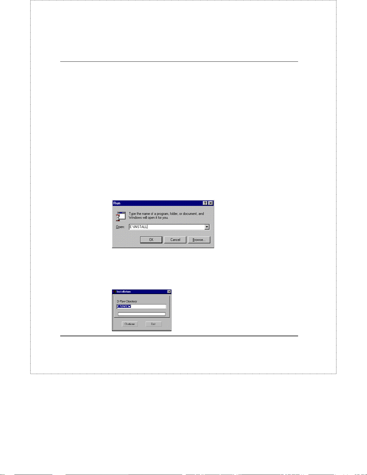
If you are using Windows 3.1, choose Run… from the Program
Manager’s File menu. Under Windows 95, choose Run… from the
Start menu on the taskbar. When the dialog box appears, type the
pathname of the Install program on the CD-ROM drive
E:\INSTALL
(
)
4.
Click OK. The installation program will start.
5.
When the program prompts for your D-View Directory, enter the
pathname of the directory where you installed D-View, and click
Continue.
6 Installing the Management Module
Page 9
DGS-3204 Ethernet Switch Management User’s Guide
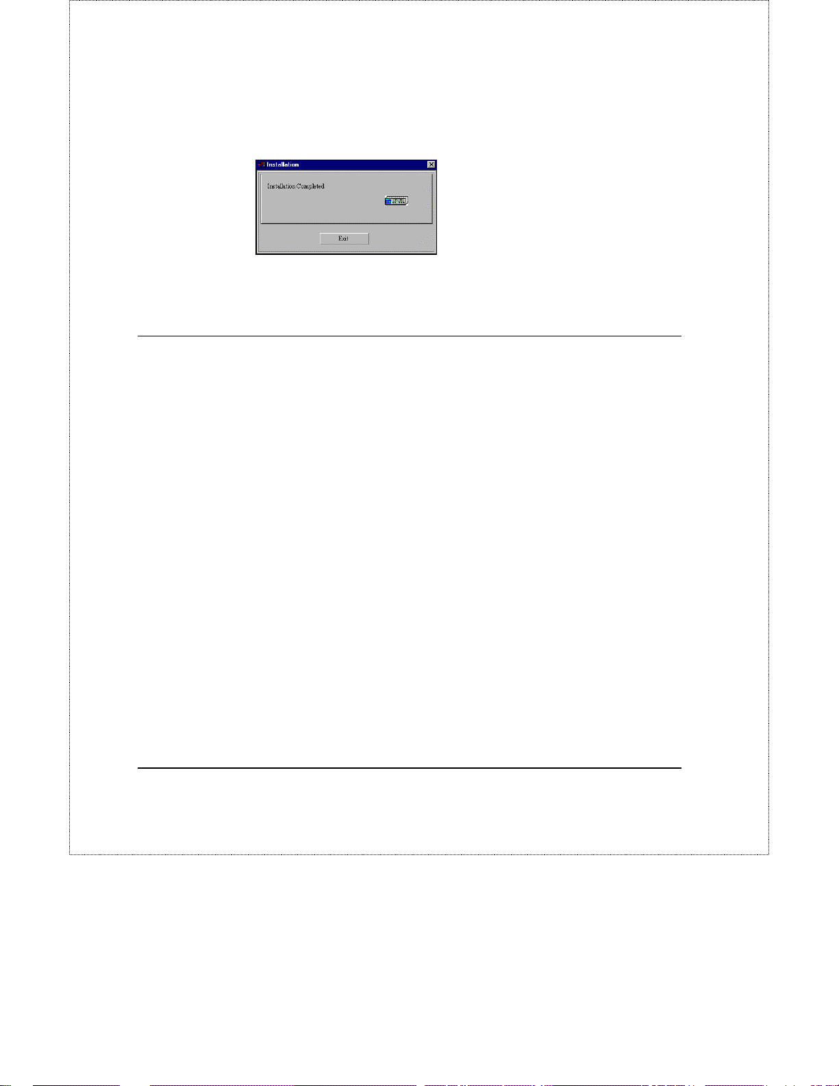
6.
The installation program will install all of the necessary files onto your
system. When it is finished, it will display the following dialog:
Click on the Exit button. The D -V iew network management system is now ready
to manage DGS-3204 Ethernet switches.
Preparing the Switch for Management
You will need to make sure that your switch is properly set up before you can
use the management module:
♦ Ensure that the switch is connected to the same network as the network
management station.
♦ Ensure that the switch’s TCP/IP settings are set properly. If the switch is
on the same local network, the network portion of the switch’s IP address
needs to be the same as that of the network management station. If they
are on separate LANs, the TCP/IP gateway (router) field of both the
switch and the router need to be set properly so that information can be
routed properly between the switch and the management station.
For more information about these and other items, consult the DGS-3204
hardware User’s Guide.
Installing the Management Module 7
Page 10
DGS-3204 Ethernet Switch Management User’s Guide
DGS-3204 Management
Adding your DGS-3204 Switch to the Map
Before you can manage individual DGS-3204 Ethernet switches, you need to
add them to your D-View network map. You can do this either by:
♦ Using D-View’s Auto Discover capability to add all new SNMP-
manageable devices to the map.
♦ Using the Add-Modify Map Device command to place each switch on the
map.
To use the second method:
1.
Press the Add/Modify a device on the map button shown below.
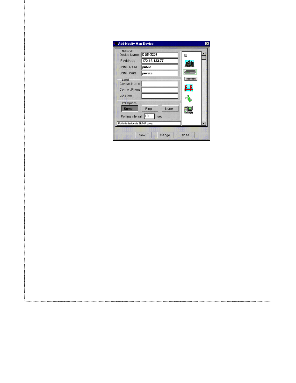
2.
Select the DGS-3204 from the icon list at the right of the Add-Modify
Map Device dialog.
8 DGS-3204 Management
Page 11
DGS-3204 Ethernet Switch Management User’s Guide
3.
Give the switch a name, and enter its IP address and SNMP community
names.
4.
Click on New.
The DGS-3204 switch icon should now be displayed on your network map as
shown below.
DGS-3204 Management 9
Page 12

DGS-3204 Ethernet Switch Management User’s Guide
The Module Display
Double-clicking on the icon in the network map causes the module display to
open. The module display is used to monitor and perform network management
functions on the selected device. The module display for the DGS-3204 appears
as follows:
Menu Buttons T he Configuration, Monitor, Reset, and Help buttons
♦
display their respective pull-down menus. The items listed in these
menus are described later on in this manual.
10 DGS-3204 Management
Page 13
♦
♦ Ports Each of the 1000BASE-SX ports on the front panel are depicted.
♦ Port Status Indicators There are corresponding port status indicators
Selecting Ports
DGS-3204 Ethernet Switch Management User’s Guide
Error Status Line This line displays messages describing error s that
occur when the module is unable to obtain information it needs. When an
error occurs, a red border appears around the error status line.
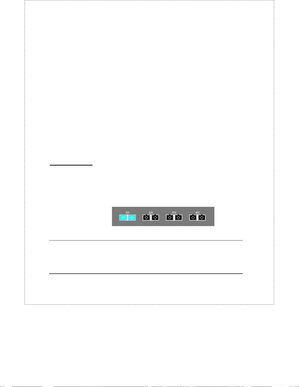
You can select individual ports to perform operations on them. Clicking
on the gray area immediately surrounding the ports will deselect the port
and select the switch as a whole.
for each of the ports on the switch. Each port indicator can be interpreted
as follows:
Link Lights green when the port is connected to a powered-on
◊
Gigabit Ethernet device.
◊ Act Lights blink off briefly when information is transmitted or
received on the port.
◊ Full Lights green when the port is operating in full-duplex.
Many of the switch management functions can be applied to the switch itself, or
to a particular port. You can select an individual port by clicking on the port
itself. The color of the port will change to indicate that you have selected it (as
shown below). You can select the switch itself by clicking in the gray area
surrounding the ports, so that none of the ports are selected.
Menu Buttons
The menu buttons on the module - Configuration, Monitor, Reset, and Help –
are used to access all the configuration settings, polling parameters and viewing
DGS-3204 Management 11
Page 14
DGS-3204 Ethernet Switch Management User’s Guide
tables used in manage ment. The section below addresses the function and use of
each item in the menu button’s drop-down menus.
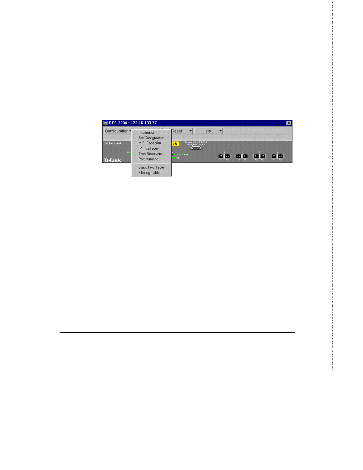
Configuration Menu Button
The Configuration menu contains options that allow you to get information
about current settings, configure switch parameters and setup the switch for
monitoring. T he configuratio n menu a ppears as follows:
Information
There are two Information windows; one for the switch as a whole, and one for
the individual ports.
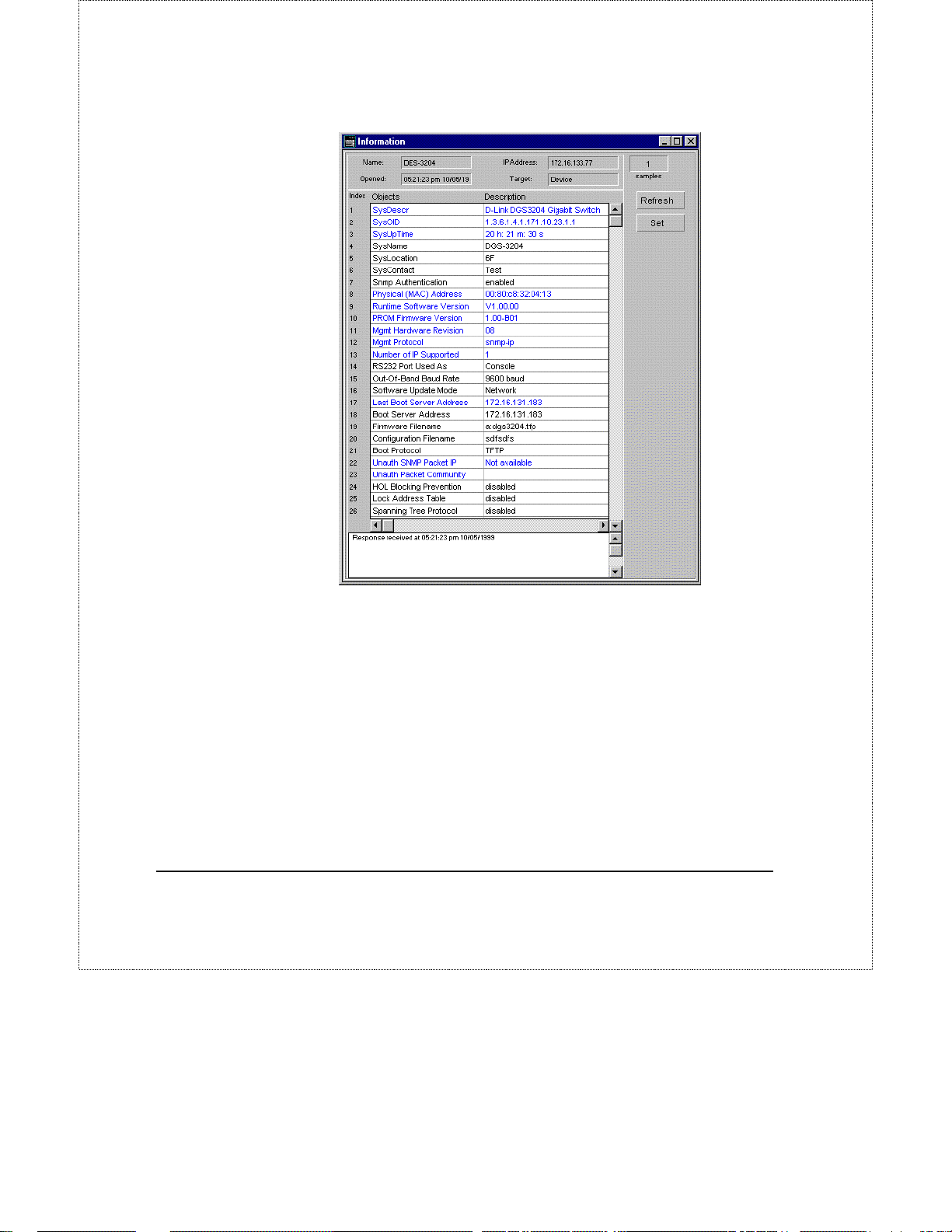
Switch Information
Choosing the first item – Information - in the Configuration menu when the
switch is selected (an individual port is not selected) causes the following
window to open:
12 DGS-3204 Management
Page 15
DGS-3204 Ethernet Switch Management User’s Guide
The values in the window that are displayed in black can be changed either in
the D-View management module or by using the console program; values in blue
are fixed either by the hardware or by the switch’s firmware.
Clicking on the Set button allows you to configure settings for the switch, and
opens the Set Configuration window described later in this manual.
The items displayed in the Switch Information table are described as follows:
♦
SysDescr
♦
SysOID
DGS-3204 Management 13
A description of the switch type.
The SNMP Object Identifier for this switch model.
Page 16

DGS-3204 Ethernet Switch Management User’s Guide
♦
SysUpTime
or since the last time the switch was reset.
♦
SysName
changing this setting can be found in the Set Configuration section below.
♦
SysLocation
of the switch. Information on changing this setting can be found in the Set
Configuration section below.
♦
SysContact
find the person responsible for the switch. Information on changing this
setting can be found in the Set Configuration section below.
♦
Snmp Authentication
manager whenever an attempt is made to access the switch using an
invalid SNMP login password.
♦
Physical (MAC) Address
switch.
♦
Runtime Software Version
switching software that drives the switch.
♦
PROM Firmware Version
stored in a PROM chip that takes the switch through that startup
sequence.
The amount of time that the switch has been powered on,
A user-assigned name for the switch. Information on
A user-assigned description for the physical location
User-defined contact information describing how to
Enables a trap to be sent to the network
The physical (MAC) address of the
Version number for the
Version number for the software
♦
Mgmt Hardware Revision
management hardware.
♦
Mgmt Protocol
hardware.
♦
Number of IP Supported
available for use for switch management. This will be 2 if the SLIP (Outof-Band) interface is enabled, and 1 if only the in-band Gigabit Ethernet
interface is available.
♦
RS232 Port Used As
configured to support a console terminal connection or a SLIP
connection.
14 DGS-3204 Management
Protocols supported by the switch’s management
Version number for the switch’s
The number of TCP/IP channels
Displays whether the RS232 port is
Page 17

DGS-3204 Ethernet Switch Management User’s Guide
Out-Of-Band Baud Rate
♦
is set to operate at.
Software Update Mode
♦
setup to download new software from a TFTP server on the Network, or
directly from a SLIP server.
Last Boot Server address
♦
used when using BootP or TFTP to boot up the server.
Boot Server Address
♦
currently used to boot up the switch.
Firmware Filename
♦
of the firmware image file. This file is switching software used to replace
(upgrade) the existing switching software in the switch.
Configuration Filename
♦
configuration file, which contains all settings in the switch.
Boot Protocol
♦
will be used to boot the switch.
Displays the protocol – BootP or TFTP - that
Displays the baud the RS232 port
Displays whether the switch is
Displays the last IP Address
Displays the IP Address of the server
Displays the complete path and filename
Displays the filename of the
♦
Unauth SNMP Packet IP
(unauthorized) SNMP community name is received, this entry shows the
source IP address of the most recent unauthorized packet.
♦
Unauth packet community
(unauthorized) SNMP community name is received, this entry shows the
community name the most recent unauthorized packet was using.
♦
HOL State
disabled.
♦
Lock Address Table
locked or unlocked.
♦
Spanning Tree Protocol
Tree Protocol is enabled or disabled on the switch.
For more detailed explanations on the function and use of the above items,
please refer to the DGE-3204 User’s Guide.
DGS-3204 Management 15
Displays whether Head-Of-Line blocking is enabled or
When a reque s t with a n unknown
When a reque s t with a n unknown
Displays whether the Forwarding Table is
Displays whether the Spanning
Page 18
DGS-3204 Ethernet Switch Management User’s Guide
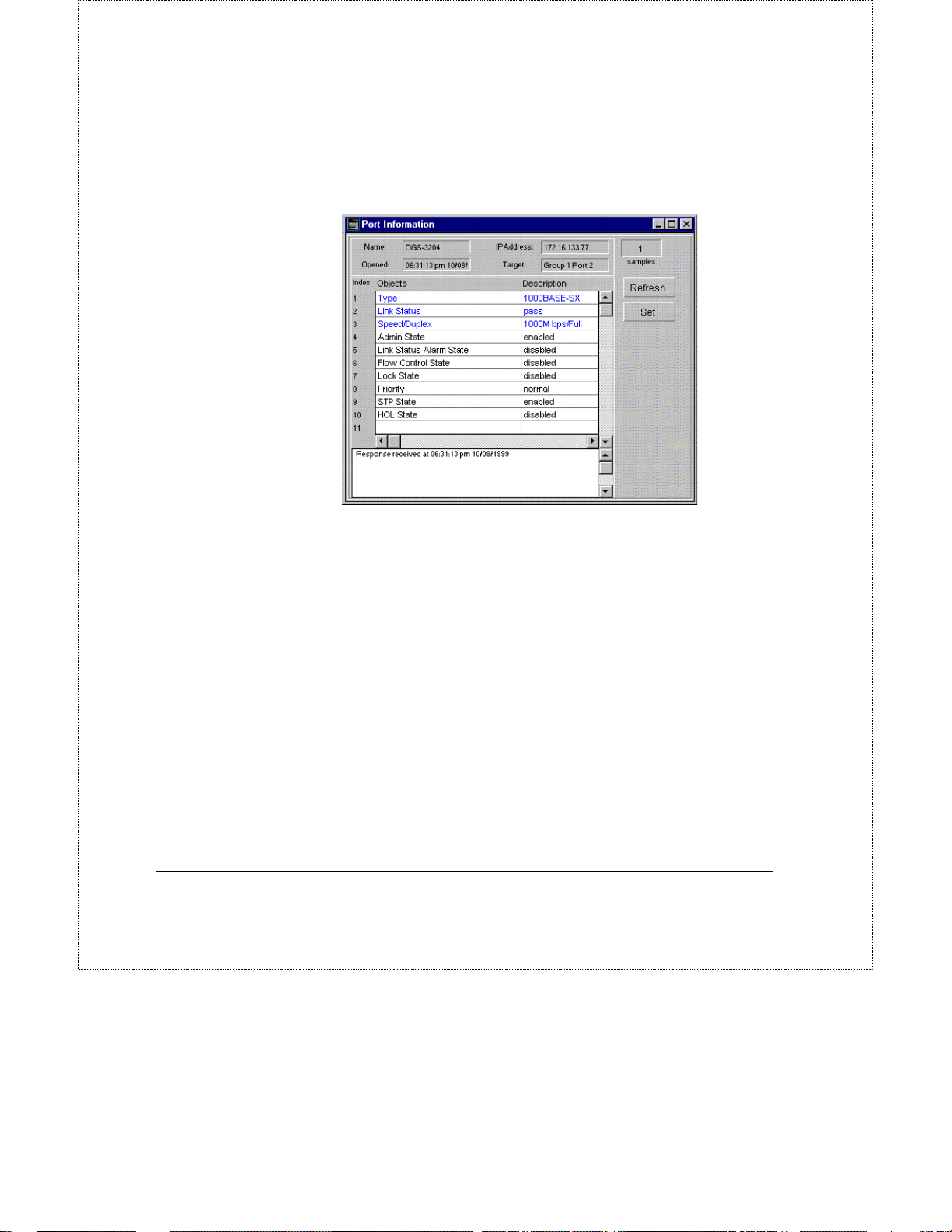
Port Information
Choosing the first item – Information - in the Configuration menu when an
individual port is selected (colored blue) causes the following window to open:
Tip: Double-clicking on the port will also cause the above window to open.
The values in the window that are displayed in black can be changed either in
the D-View management module or by using the console program; values in blue
are fixed either by the hardware or by the switch’s firmware.
Clicking on the Set button allows you to configure settings for the selected port,
and opens the Port Configuration window described later in this manual.
The items displayed in the Port Information table are described below
♦
♦
16 DGS-3204 Management
The type of connection supported by the port.
Type
Link Status
another Gigabit Ethernet device that is powered on. If no such connection
exists, it will display Fail.
Displays Pass when the port has a connection to
Page 19

DGS-3204 Ethernet Switch Management User’s Guide
♦
Speed/Duplex
the port. All ports on the DGS-3204 can only be set to run at 1Gbps
(1000Mbps) at Full duplex.
♦
Admin State
partitioned from the rest of the network. In this partitioned state, it will
only be able to accept management packets. All other packets will be
dropped.
♦
Link Status Alarm State
Alarm, which sends a trap to the network manager whenever the Link
Status changes, is enabled or disabled.
♦
Flow Control State
control is enabled or disabled on the port.
♦
Lock State
locked or not. When locked, automatic learning for all stations connected
to this port will stop and entries in the Forwarding Table for all devices
residing on this port will age out. The only traffic this port will allow is
traffic from machines manually entered in the Static Forwarding Table.
♦
Priority
given a high, normal or low priority in the switch’s packet queuing.
♦
STP State
disabled on this port.
Displays the current speed and duplex settings for
When you disable the Admin State, the port will be
Displays whether the Link Status
Displays whether IEEE 802.3x flow
Displays whether the Forwarding Table for this port is
Displays the whether traffic arriving at this port will be
Displays whether Spanning T ree Proto col is enabled or
♦
HOL State
enabled or disabled on this port.
For more detailed explanations on the function and use of the above items,
please refer to the DGE-3204 User’s Guide.
Displays whether Head-Of-Line Blocking Prevention is
Set Configuration
There are two Configuration windows; one for the switch as a whole, and one
for the individual ports.
DGS-3204 Management 17
Page 20
DGS-3204 Ethernet Switch Management User’s Guide
Switch Configuration
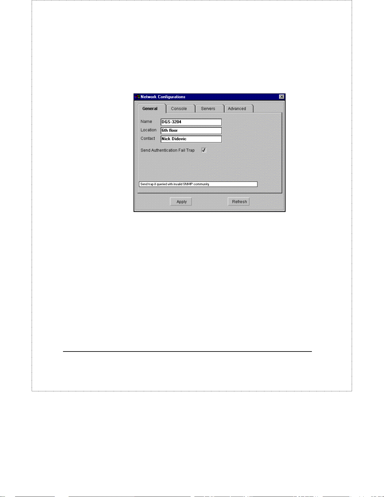
Choosing the second item – Set Configuration - in the Configuration menu
when the switch is selected (an individual port is not selected) causes the
following window to open.
There ar e four tabs runni ng along the top – General, Console, Servers,
Advanced – which allow you to configure a number of settings for the switch.
General
As shown in the Information window, the switch maintains the
SysLocation
accounting. You can set these fields in the Network Configurations dialog box
in this window.
The Send Authentication Fail Trap setting, if checked, enables a trap to be sent
to the network manager whenever an attempt is made to access the switch using
an invalid SNMP login password.
After making changes in the window, be sure to click on the Apply button to
activate them on the switch before clicking on another tab or closing the
window.
18 DGS-3204 Management
SysContact
, and
variables to assist with tracking and
SysName
,
Page 21
DGS-3204 Ethernet Switch Management User’s Guide
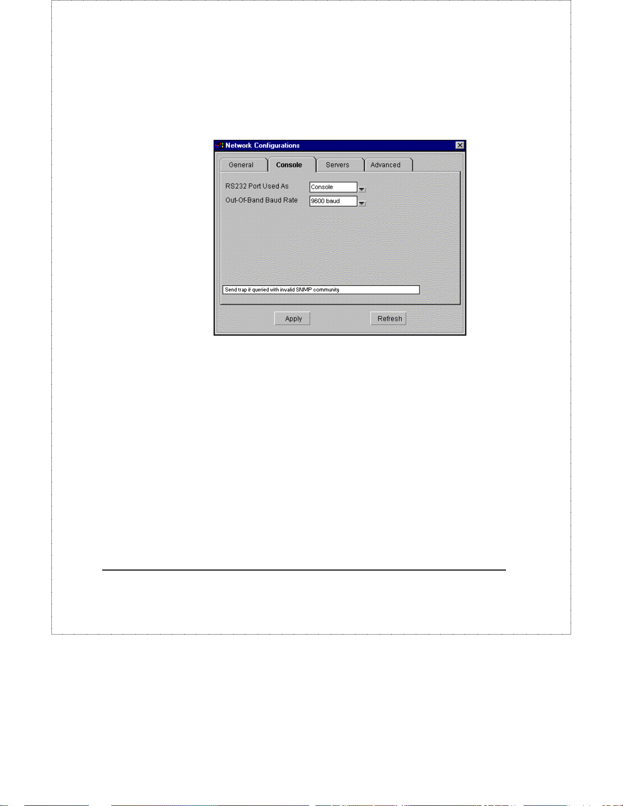
Console
The Console tab of the Network Configuration dialog allows you to set
parameters for the Diagnostics RS232 port located on the front of the switch.
Each field is described below:
♦ RS-232 Port Used As Sets the Diagnostic RS232 port to either Console
or SLIP. The Console setting allows the port to be used for terminalbased console management. The SLIP setting configures the RS232 port
for SLIP co mmunications.
♦ Out-of-band Rate Determines the bit rate of the RS232 port. When
being used in Console mode, it should be set to 9600 baud.
Changes will not take affect unless the Apply button is clicked on.
Servers
The DGS-3204 Ethernet switch stores its internal software (firmware) in flash
memory, which allows you to update the switch with new versions of the
firmware when they become available. In addition, many of the switch’s
operational parameters can be set using a flexible configuration file stored on a
centralized server.
DGS-3204 Management 19
Page 22
DGS-3204 Ethernet Switch Management User’s Guide
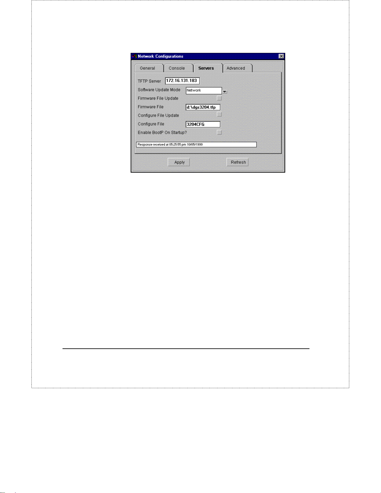
Each item is described below:
♦ TFTP Server This box should contain the IP address of the TFTP
server, if any, you are using on your network.
Software Update M ode Defines the method you wish to use to upload
♦
new runtime switching software onto the switch. Choosing Network
causes the switch to look for the software image file on the TFTP server
defined above; choosing SLIP allows the software to be uploaded from a
SLIP workstation or server directly connected to the RS232 port.
♦ Firmware File Update Clicking on the box to the right so that a check
(!) appears in it, tells the switch to upload new runtime switching
software the next time it is restarted or rebooted.
♦ Firmware File This field should contain the complete path and filename
for the switching software image file.
♦ Configuration File Update Clicking on the box to the right so that a
check (!) appears in it, tells the switch to upload settings from a
configuration file the next time it is restarted or rebooted.
20 DGS-3204 Management
Page 23
DGS-3204 Ethernet Switch Management User’s Guide
Configuration File This field should contain the complete path and
♦
filename for the configuration file you wish to use to upload settings to
this switch.
♦ Enable BootP On Startup When checked (!), the server will utilize the
BootP protocol to get its IP address, subnet mask and gateway IP the next
time it is restarted or rebooted.
For more information about DGS-3204 configuration files, consult the
appendix to the DGS-3204 hardware User’s Guide, or the samples included
on the management module installation disk. For more information about
using the TFTP and BOOTP servers, consult the D-View User’s Guide.
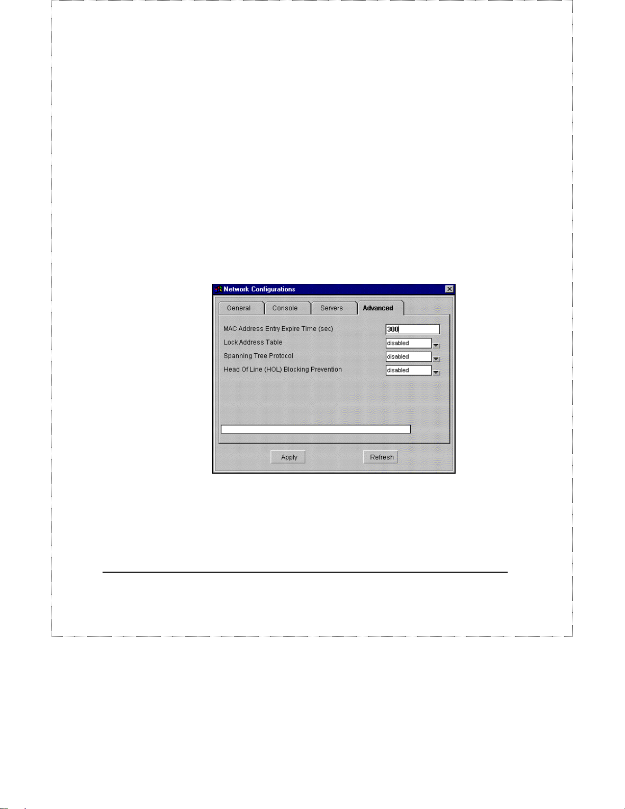
Advanced
Clicking on the Advanced tab displays the following window and allows you to
configure the switch fo r more advanced functions.
Each of the fields is described below:
♦ MAC Address Entry Expire Time (sec) This field allows you to set the
aging time for entries in the Forwarding table.
Lock Address Table When Enabled, the forwarding table will not learn
♦
any more addresses and all entries in the forwarding table will be static
DGS-3204 Management 21
Page 24
DGS-3204 Ethernet Switch Management User’s Guide
and will not age out. When Disabled, the automatic learning function of
the switch will be turned on.
Spanning Tree Protocol Enables/Disables Spanning Tree on the
♦
switch.
Head Of Line (HOL) Blocking Prevention Enables/Disables Head-Of-
♦
Line Blocking o n the switch.
For more detailed explanations, please refer to the Port Configuration section
below.
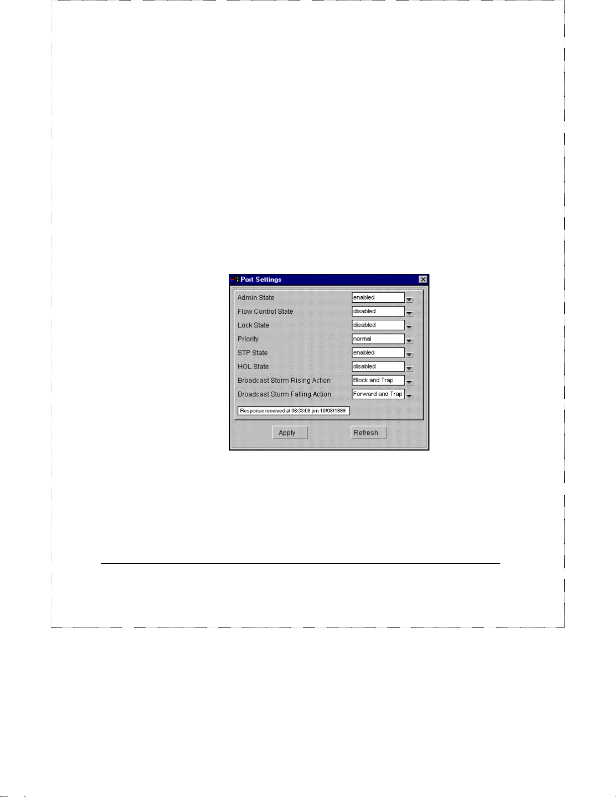
Port Configuration
Choosing the second item – Set Configuration - in the Configuration menu
when an individual port is selected (colored blue) causes the following window
to open:
Tip: Double-clicking on the port will also cause the above window to open.
Items in the above window are described as follows:
♦
Admin State
partitioned from the rest of the network. In this partitioned state, it will
only be able to accept management packets. All other packets will be
dropped.
22 DGS-3204 Management
When you disable the Admin State, the port will be
Page 25

DGS-3204 Ethernet Switch Management User’s Guide
♦
Flow Control State
control on the port. Flow control allows the port to send a Pause packet to
a transmitting IEEE 802.3x-compliant device, so that it’s buffers don’t
overflow and data is not lost.
♦
Lock State
connected to this port will stop and entries in the Forwarding Table for
all devices residing on this port will age out. The only traffic this port
will allow is traffic from machines whose MAC address is manually
entered in the Static Forwarding Table.
♦
Priority
normal or low. Higher priority packets are processed first in the switch’s
packet queue.
♦
STP State
Tree allows backup connections and prevents signal loops on the
network.
♦
HOL State
on this port. Head-of Line blocking occurs when a packet originating on
Port 1, for instance, needs to be forwarded to Ports 2 and 3. If Port 2 is
occupied (causing the packet to be held in memory until the port is free),
the packet destined for Port 3 will also be delayed. Cumulatively, these
delays can have a noticeable effect on overall network performance.
Enabling the HOL State prevents Head-of-Line blocking from occurring.
When locked, automatic learning for all stations
Sets the priority for traffic arriving at this port to high,
Enables or disables Spanning Tree on this port. Spanning
Enables or disables Head-Of-Line Blocking Prevention
Enables or disables IEEE 802.3x flow
♦
Broadcast Storm Rising Action
activated when the switch detects that 80% of packets on the segment
connected to the port are broadcast packets and the port surpasses 30%
utilization. When these criteria are met, the port can be configured to Do
Nothing, Block or Block and Trap. The Do Nothing setting cause s the
switch to operate normally, in other words, ignore the broadcast storm
condition. The Block setting causes the port to drop all broadcast frames,
thus isolating the broadcast storm. Block and Trap performs the same
action as Block, except it also sends a trap to the designated Trap
Recipient informing them of the situation.
♦
Broadcast Storm Falling Action
activated when a Broadcast Storm Rising Action has occurred and the
switch detects that port utilization has dropped below 10%. This setting
DGS-3204 Management 23
This setting will be
This setting will be
Page 26
DGS-3204 Ethernet Switch Management User’s Guide
can be configured to Do Nothing, Forward or Forward and Trap. The
Do Nothing setting causes the switch to operate normally, in other words,
ignore the situation. If the port had met the Broadcast Storm Rising
Action criteria and started Blocking broadcast packets, it will continue
doing so. The Forward setting causes the port to begin forwarding
broadcast frames, thus removing the Blocking state imposed by the
Broadcast Storm Rising Action. Forward and Trap performs the same
action as Forward, except it also sends a trap to the designated Trap
Recipient informing them of the situation.
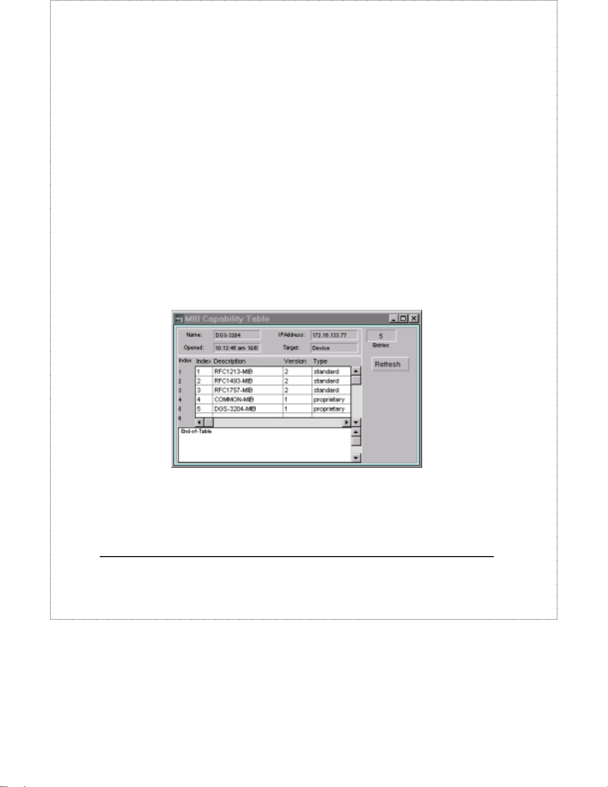
MIB Capability Table
The MIB Capability Table shows which MIBs are used by the DGS-3204
switch.
o view the MIB Capability Table, choose MIB Capability fro m the
Configuration menu. The MIB Capability Table dialogue box will appear.
Press the Refresh button to force the display to match the switch’s current status.
24 DGS-3204 Management
Page 27
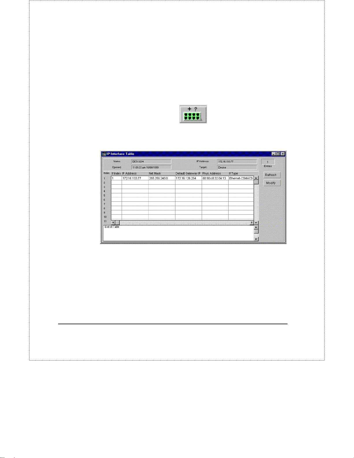
IP Interfaces
IP parameters can be viewed and changed from the management modules when
necessary. After changing the IP address, your connection to the switch will be
cut off. Change the settings in the D-View map by selecting the DGS-3204 icon
in the map and clicking on the Add/Modify a device on the map button (shown
below) to update the IP address to the new setting.
Clicking on IP Intefaces in the Configuration menu displays the following
window:
DGS-3204 Ethernet Switch Management User’s Guide
The fields displayed in the table are:
♦ IF Index Displays the IP Interface which the other settings are used on.
The DGS-3204 contains only one IP Interface.
♦ IP Address Shows the IP address of the given Interface.
Net Mask Shows the subnet mask for the network that the switch is
♦
connected to.
DGS-3204 Management 25
Page 28
DGS-3204 Ethernet Switch Management User’s Guide
Default Gateway IP Shows the IP Address of the gateway router where
♦
packets destined for IP addresses outside of the local network should be
sent for forwarding.
♦ Phys Address Shows the physical (MAC) address of the switch.
♦ If Type Describes the type of IP Interface. The DGS-3204 supports
CSMA/CD the standard Ethernet protocol.
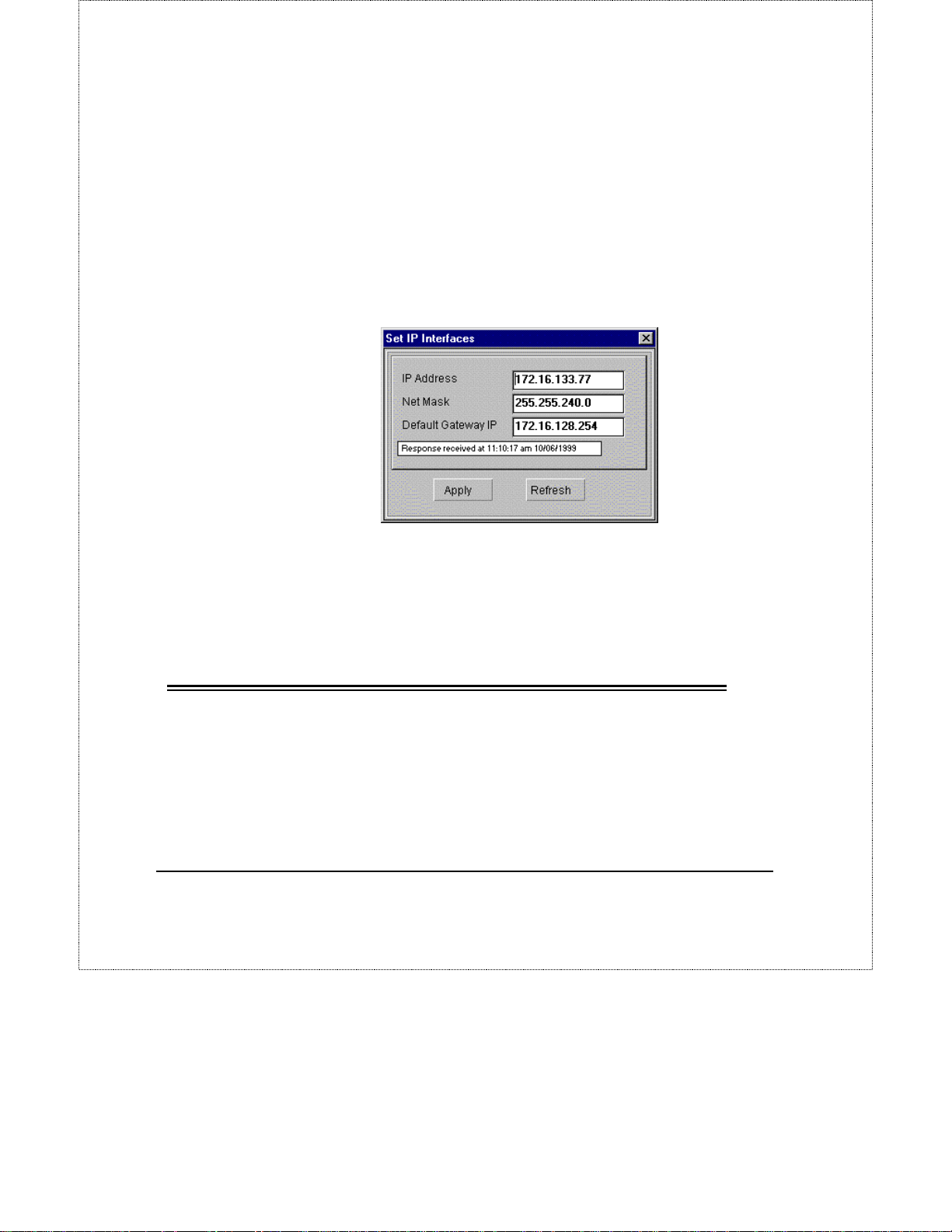
To change the switch’s IP settings, press the Modify button in the IP Interface
Table window. The Set IP Interfaces (shown below) window will be displayed:
When all changes have been made, press Apply then restart the switch to let the
changes take effect.
NOTE
Changing the IP settings may make the switch temporarily
inaccessible from the management station. Be sure to update
the switch’s map entry after changing its IP address.
Trap Receivers
Your DGS-3204 Ethernet switch can send SNMP traps to network management
stations when exceptional events happen. These include:
♦ When the switch is powered on.
♦ Whenever a user-defined threshold condition occurs.
26 DGS-3204 Management
Page 29
DGS-3204 Ethernet Switch Management User’s Guide
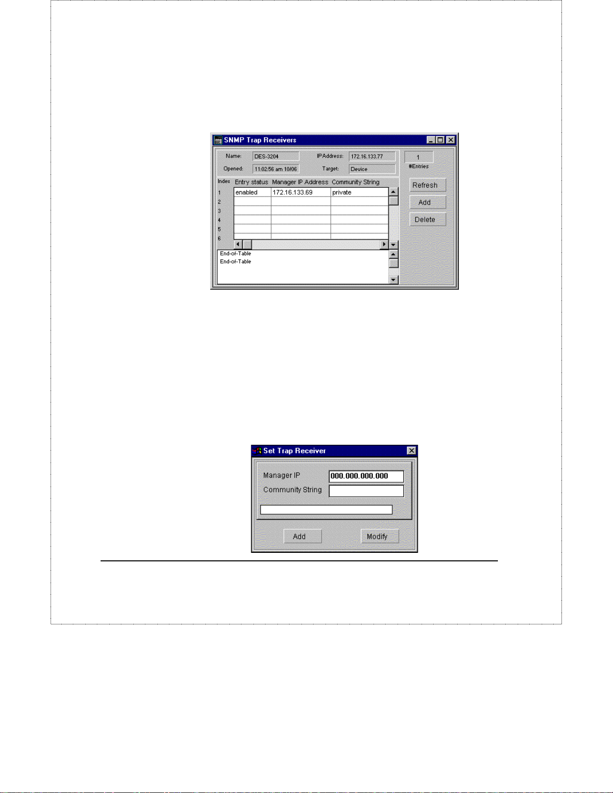
The switch requires you to designate the network management stations that will
receive these traps. To view the trap recipients, select Trap Receivers from the
Configuration menu.
The fields displayed are:
♦ Entry Status Shows whether or not this entry is valid.
♦ Manager IP Address The IP address of the trap recipient.
♦ Community Shows the SNMP community name that will be used for the
traps sent to this recipient.
To Add a new trap receiver to the table, click on the Add button to the right.
To modify the Manager IP address or community string for an entry, click on the
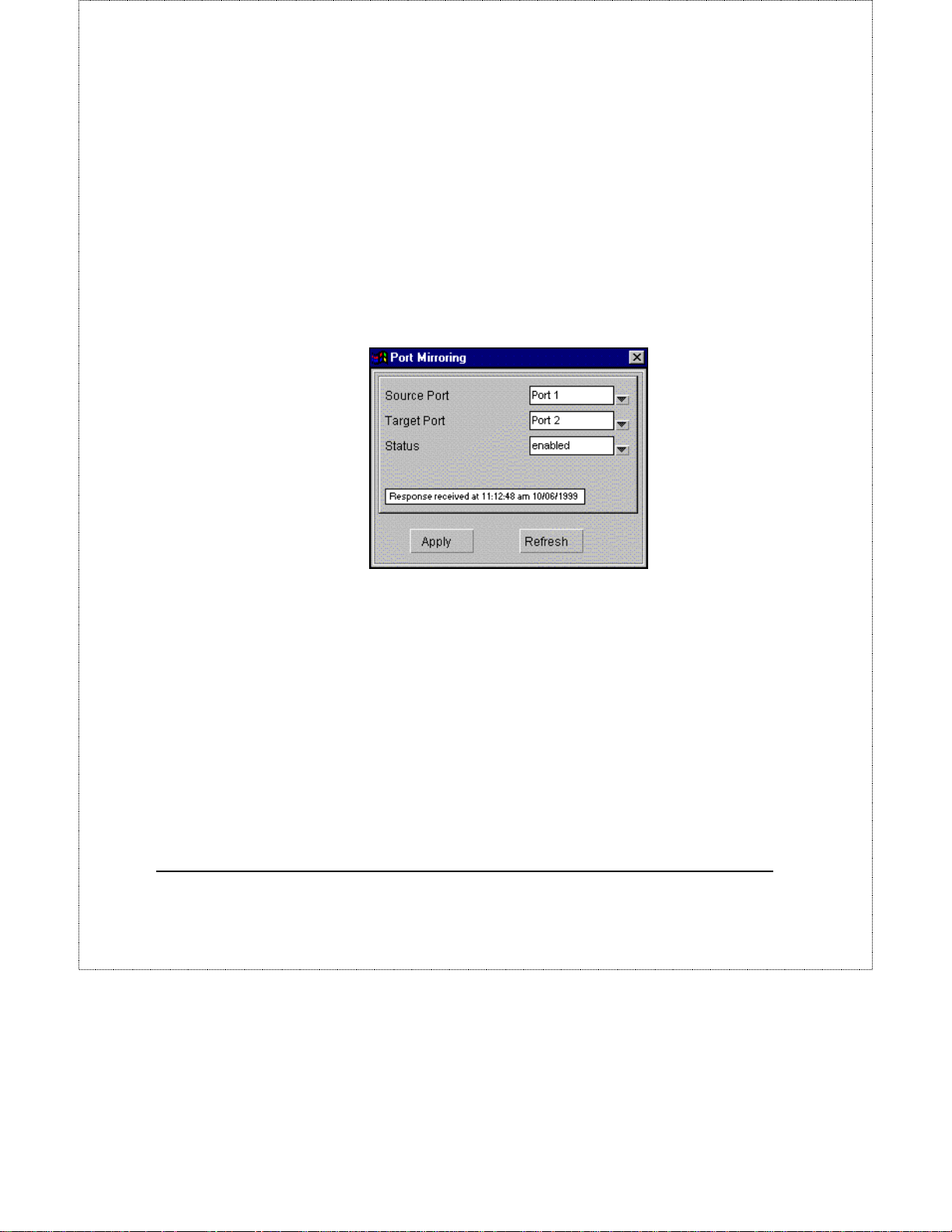
entry so that it is highlighted and then click on the Add button to the right. The
Set Trap Receiver dialog box will be displayed:
DGS-3204 Management 27
Page 30
DGS-3204 Ethernet Switch Management User’s Guide
When all changes have been made, click on the Add button if adding a new
entry, or click on the Modify button when modifying an existing entry.
For more information about changing the switch’s trap configuration, see the
DGS-3204 hardware User’s Guide.
Port Mirroring
The DGS-3204 allows you to mirror traffic on one port to another port for
analysis. Once setup and enabled, the switch will take all traffic from the Source
port and mirror it on the Target port.
Each of the fields is described below:
♦ Source Port This is the port whose traffic you wish to analyze.
♦ Target Port The port where you have a sniffer or PC with packet
analysis software directly attached to analyze data packets.
Status Enables/disables port mirroring.
♦
28 DGS-3204 Management
Page 31
Static Fwd Table
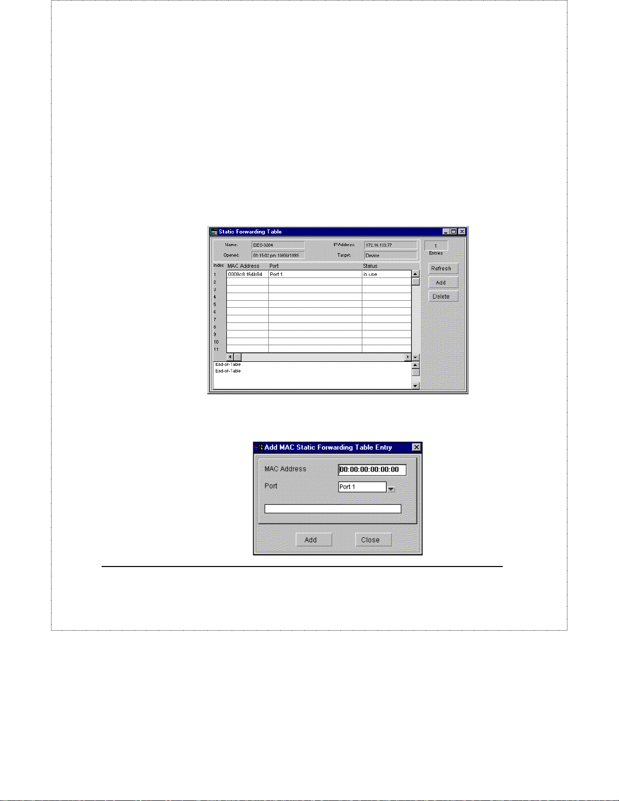
The Static Forwarding Table allows you to assign permanent forwarding
criteria for specific MAC addresses. Thus, whenever the switch receives a
packet destined for a MAC address in the table, it will always be forwarded
to the associated port.
To view the Static Forwarding Table, select Static Fw d Table from the
Configuration menu. This causes the following window to appear:
DGS-3204 Ethernet Switch Management User’s Guide
To add an entry to the table, click on the Add button on the on the right side of
the Static Forwarding Table window. The Add MAC Static Forwarding
Table Entry dialog box will be displayed:
DGS-3204 Management 29
Page 32
DGS-3204 Ethernet Switch Management User’s Guide
The fields displayed are:
♦ MAC Address The MAC Address for the device you wish to create a
static forwarding entry for.
♦ Port The port t hrough which packets desti ned for the MAC address will
always be forwarded.
When all changes have been made, Click Apply to let the change take effect.
Filtering Table
To prevent a particular machine from accessing the network, you can filter that
machine's MAC address by entering it in the filtering table. The switch will then
neither accept packets from, nor forward packets to, the device with that MAC
address.
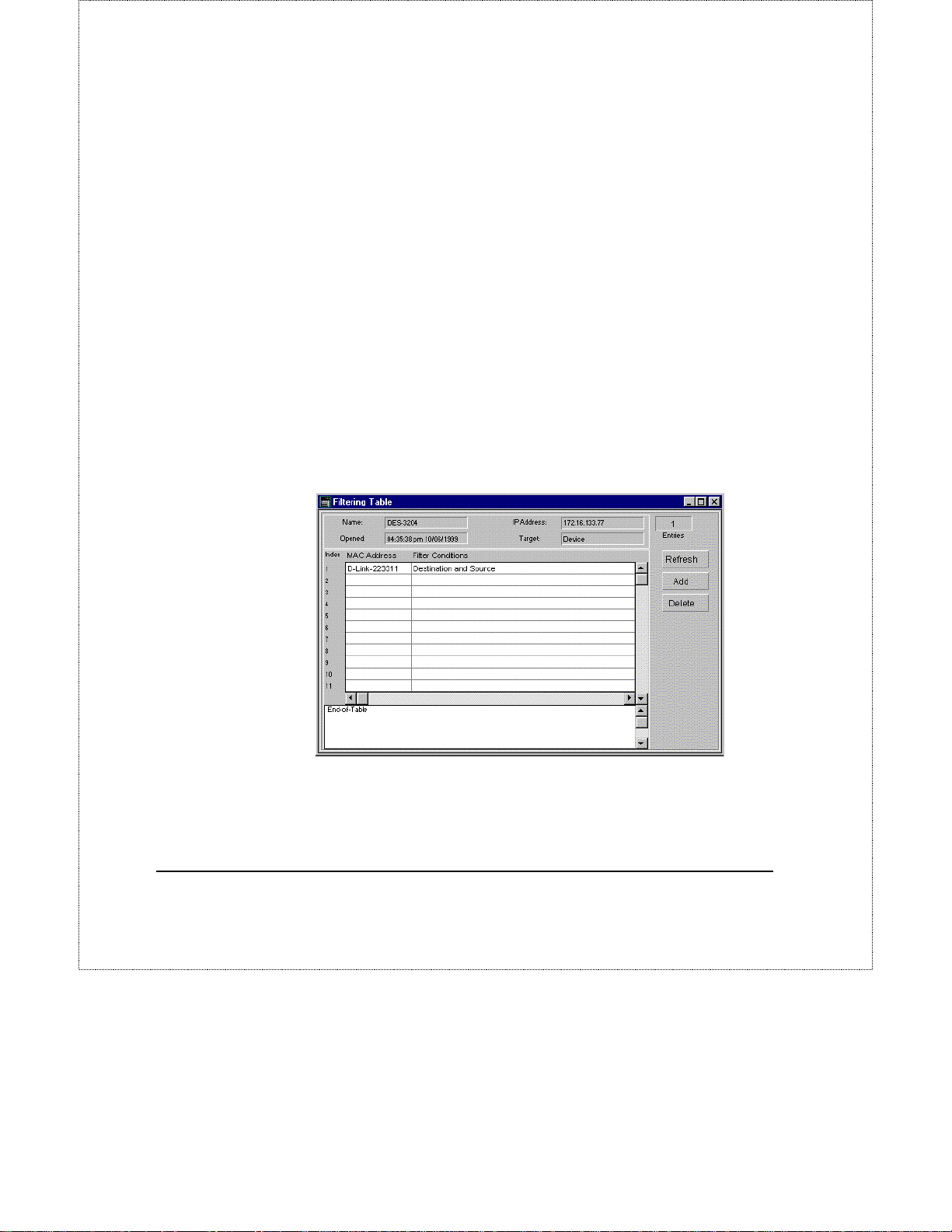
To view or edit the filtering table, choose Filtering Table from the
Configuration menu. The Filtering Table window will appear:
The items in the window are described as follows:
MAC Address All packets containing this MAC address will be dropped
♦
by the switch.
30 DGS-3204 Management
Page 33
DGS-3204 Ethernet Switch Management User’s Guide
Filter Conditions Automatically set by the DGS-3204 to Destination and
♦
Source, meaning that all packets having a destination or source MAC
address defined in the MAC Address field will be dropped.
To remove an entry from the Filtering Table, simply click on the desired
entry so that it is highlighted and then click on the Delete button on the right
side of the window.
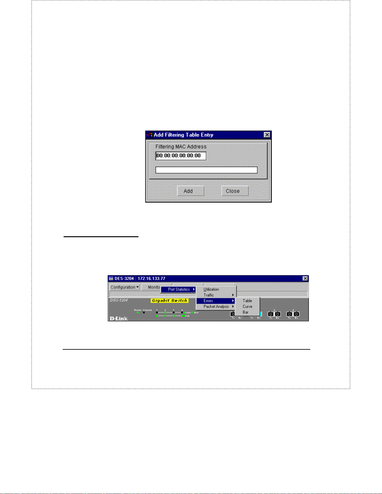
To add an entry to the filtering table click on the Add button on the right side of
the window. The following window will appear:
Enter the MAC address you wish to filter from the network in the appropriate
box. Click on the Add button to add it to the Filtering Table.
Monitor Menu Button
The DGS-3204 management module allows you to collect network statistics and
to display them in several easy-to-read forms. This section describes how you
can use the module to observe conditions on each individual port.
DGS-3204 Management 31
Page 34

DGS-3204 Ethernet Switch Management User’s Guide
Port Statistics
The module allows you to display four network statistics:
♦ Port Utilization
♦ Traffic
♦ Errors
♦ Packet Analysis
Except for Port Utilization, Ethernet statistics for a given port can be
displayed in:
◊ table form,
◊ line curve form, or
◊ bar graph form.
You can display statistics for a particular port by selecting that port and
choosing the appropriate Monitor menu item. When the switch itself selected
(as opposed to a particular port), the management module will not display
statistics.
Statistics Collected by the Switch
The management module can display the following network statistics:
♦ Utilization The percentage of network bandwidth that is being utilized.
♦ Good Bytes Sent (Bytes Tx) Counts the number of bytes successfully
sent from the port.
Good Bytes Received (Bytes Rx) Counts the total number of bytes
♦
(octets) included in valid (readable) frames.
Total Bytes Received (Total Bytes Rx) Counts the total number of bytes
♦
received on the port, whether valid or invalid frames.
♦ Good Frames Sent (Frames Tx) Counts the total number of frames
transmitted from the port.
32 DGS-3204 Management
Page 35

DGS-3204 Ethernet Switch Management User’s Guide
Good Frames Received (Frames Rx) Counts all valid frames received
♦
on the port.
♦ Total Frames Rx Counts the total number of frames received on the
port, whether valid or invalid frames.
♦ CRC Error Counts frames that fail the CRC frame integrity check. CRC
errors are usually indicative of hardware problems.
♦ Oversize Frames Counts packets received that were longer than 1518
octets (excluding framing bits, but including FCS octets) limit set by the
Ethernet standard that were otherwise well formed. This is likely caused
by a software problem.
♦ Fragments Counts packets received that were less than 64 octets in
length (excluding framing bits but includ ing FCS octets) and had either a
bad Frame Check Sequence (FCS) with an integral number of octets
(FCS Error) or a bad FCS with a non-integral number of octets
(Alignment Errors). These are normally the result of collisions.
Jabber Counts frames longer than the maximum 1518 bytes (octets) with
♦
either bad framing or an inva lid CRC. This may be due to a hardware
problem such as a malfunctioning NIC. A jabber condition can halt all
traffic on a segment.
♦ Late Collision Counts collisions that occur at or after the 64th byte
(octet) in the frame. This may indicate that delays on the Ethernet are too
long, and you have either exceeded the repeater count or cable segment
length specified in the IEEE 802.3z Ethernet standard.
♦ Dropped Frames Number of frames dropped by the switch.
♦ Undersized Frames The number of frames detected that are less than
the minimum permitted frame size of 64 bytes and have a good CRC.
Undersized frames usually indicate collision fragments, a normal network
event.
♦ Collisions A collision occurs when two devices try to transmit at the
same time. This counter tracks the number of times packets have collided
on the collision domain connected to this port. Collisions are normal in
an Ethernet network and tend to increase as network utilization rises.
Therefore, is the collision rate increases without an increase in network
utilization, it can indicate a problem.
DGS-3204 Management 33
Page 36

DGS-3204 Ethernet Switch Management User’s Guide
Frames 64Bytes Displays the number of frames with 64 bytes of
♦
information.
♦ Frames 65~127Bytes Displays the number of frames with 65 to 127
bytes of information.
♦ Frames 128~255Bytes Displays the number of frames with 128 to 255
bytes of information.
♦ Frames 256~511Bytes Displays the number of frames with 256 to 511
bytes of information.
♦ Frames 512~1023Bytes Displays the number of frames with 512 to
1023 bytes of information.
Frames 1024~1518Bytes Displays the number of frames with 1024 to
♦
1518 bytes of information.
♦ Multicast Rx The number of multicast packets received on this port.
♦ Multicast Tx The number of multicast packets transmitted on this port.
♦ Broadcast Rx The number of broadcast packets received on this port.
♦ Broadcast Tx The number of broadcast packets transmitted on this port.
Port Utilization
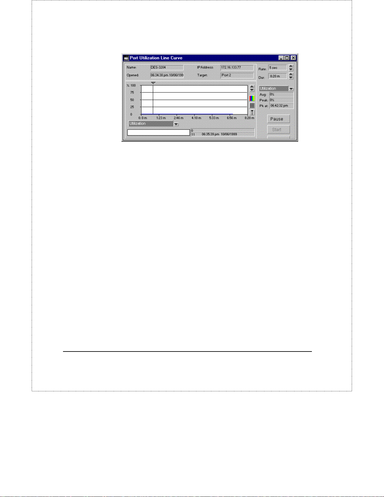
This display permits you to observe the utilization of each individual port. Select
the port that you wish to display statistics for.
To display the Port Utilization Line Curve:
1. Select a port by clicking on it. It should turn blue in color.
2. Choose Monitor from the main menu.
3. Choose Port Statistics from the Monitor menu.
4. Choose Utilization from the Port Statistics menu. The Port Utilization
Line Curve will be displayed.
34 DGS-3204 Management
Page 37
DGS-3204 Ethernet Switch Management User’s Guide
Port Traffic
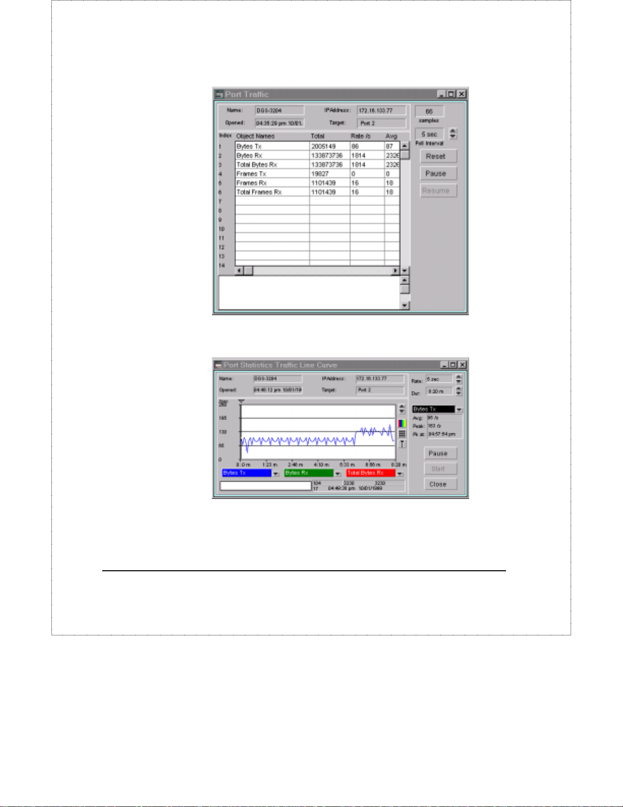
This display permits you to observe the network traffic on each individual port.
Select the port that you wish to display statistics for.
To display the Port Traffic:
1. Choose Monitor from the main menu.
2. Choose Traffic from the Monitor menu.
3. Choose Table from the Traffic menu. The Port Traffic Table will be
displayed.
DGS-3204 Management 35
Page 38
DGS-3204 Ethernet Switch Management User’s Guide
Choose Curve from the Traffic menu and the Port Statistics Traffic Line Curve
will be displayed.
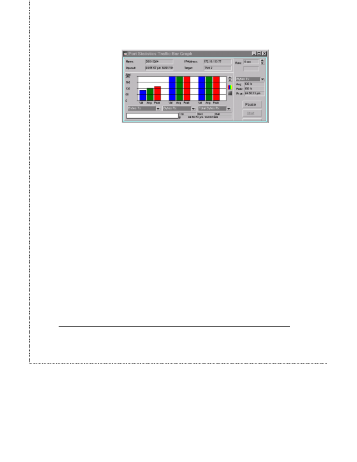
Choose Bar from the Traffic menu and the Port Statistics Traffic Bar Graph will
be displayed.
36 DGS-3204 Management
Page 39
DGS-3204 Ethernet Switch Management User’s Guide
Port Errors
This display permits you to observe the various errors on each individual port.
Select the port that you wish to display statistics for.
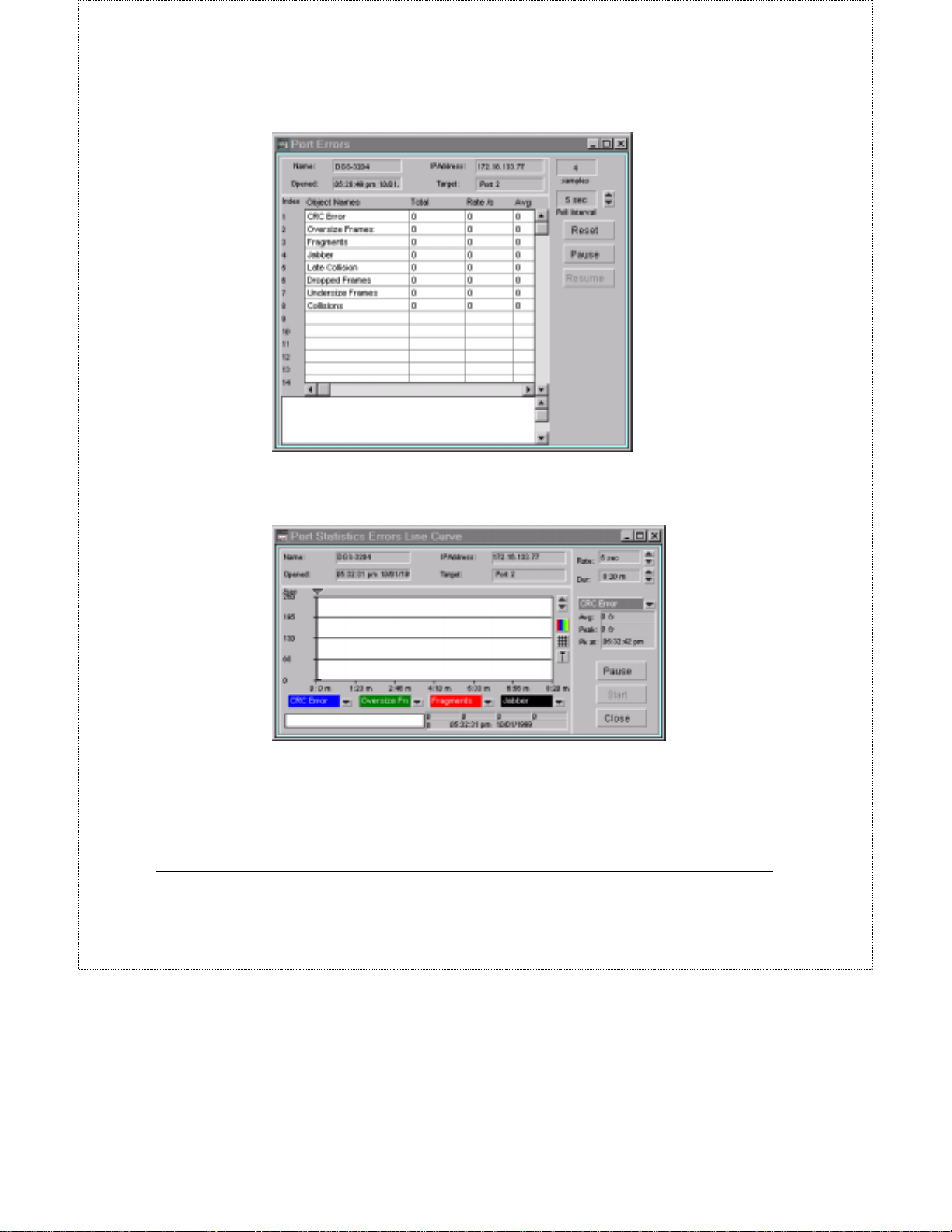
To display the Port Errors:
1. Choose Monitor from the main menu.
2. Choose Port Statistics from the Monitor menu.
3. Choose Errors from the Port Statistics menu.
Choose Table from the Errors menu. The Port Errors table will be displayed.
DGS-3204 Management 37
Page 40
DGS-3204 Ethernet Switch Management User’s Guide
Choose Curve from the Errors menu. The Port Statistics Errors Line Curve will
be displayed.
Choose Table from the Errors menu. The Port Errors table will be displayed.
38 DGS-3204 Management
Page 41
DGS-3204 Ethernet Switch Management User’s Guide
Packet Analysis
This display permits you to observe the frequency that different types of packets
arrive at an individual port. Select the port that you wish to display observe.
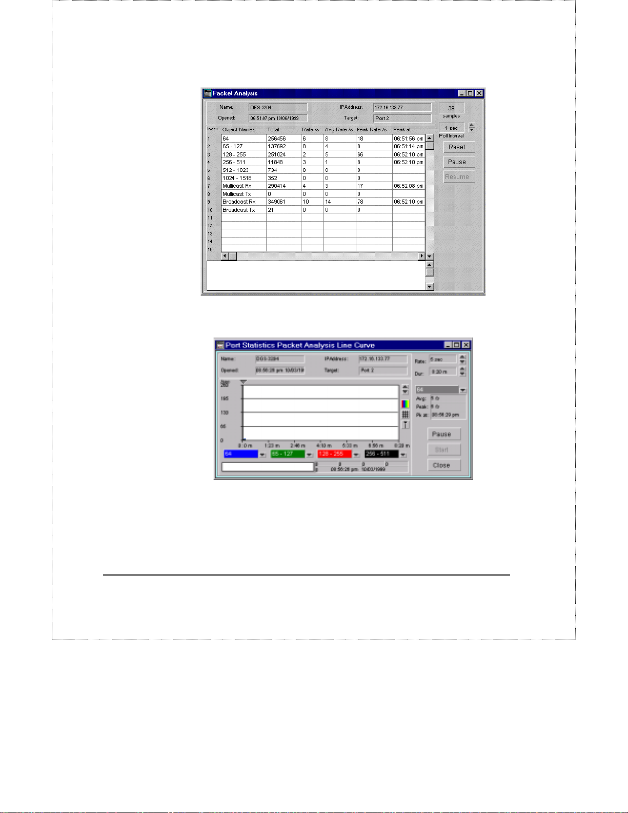
To display the Packet Analysis:
1. Choose Monitor from the main menu.
2. Choose Port Statistics from the Monitor menu.
3. Choose Packet Analysis from the Port Statistics menu.
4. Choose Table from the Packet Analysis menu. The Packet Analysis
table will be displayed.
DGS-3204 Management 39
Page 42
DGS-3204 Ethernet Switch Management User’s Guide
Choose Curve from the Packet Analysis menu. The Port Statistics Packet
Analysis Line Curve will be displayed.
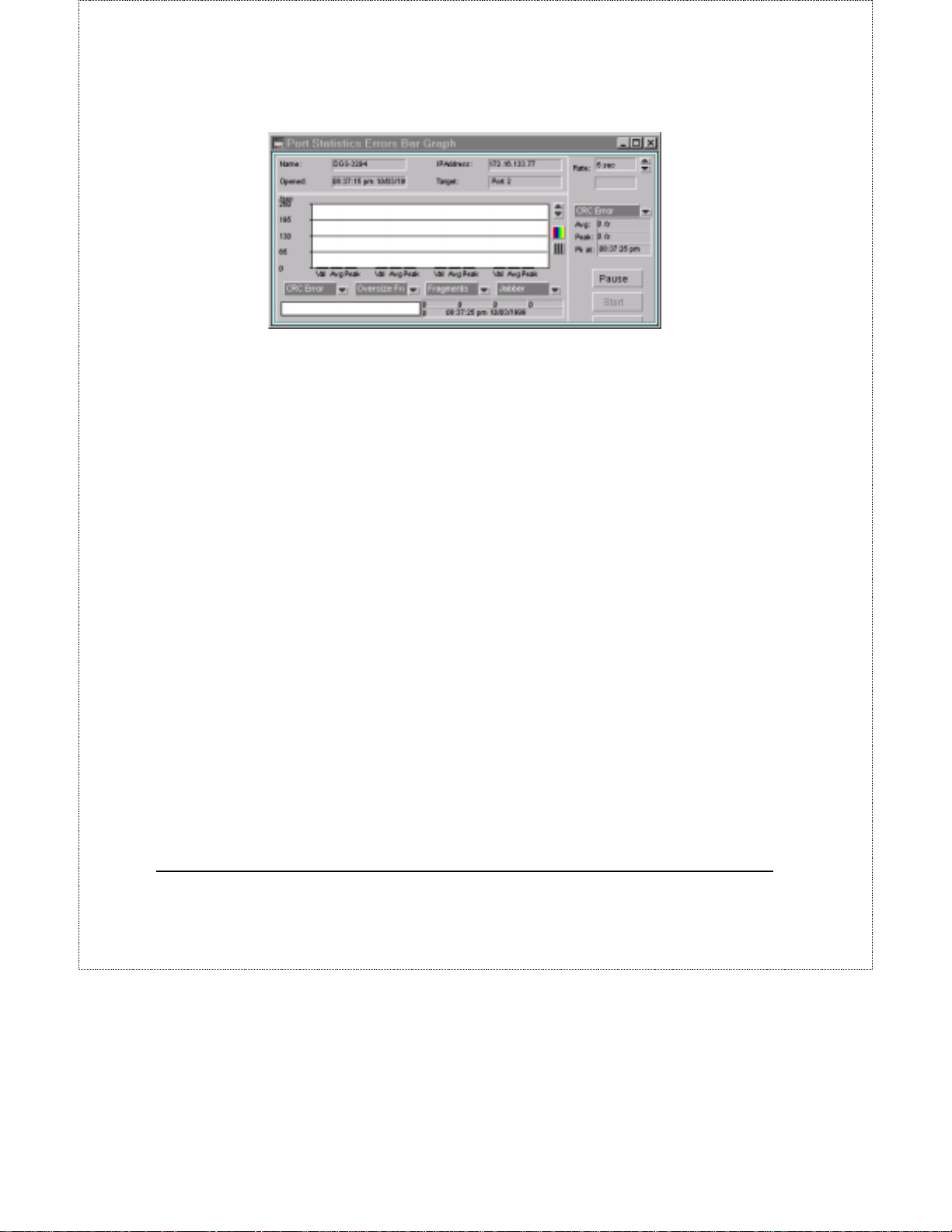
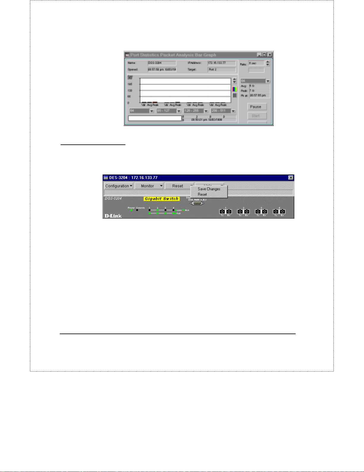
Choose Bar from the Packet Analysis menu. The Port Statistics Packet Analysis
Bar Graph will be displayed.
40 DGS-3204 Management
Page 43
Reset Menu Button
Resetting the switch will restart the switch using any new configuration settings
that have been saved. It also resets all counters and tables.
DGS-3204 Ethernet Switch Management User’s Guide
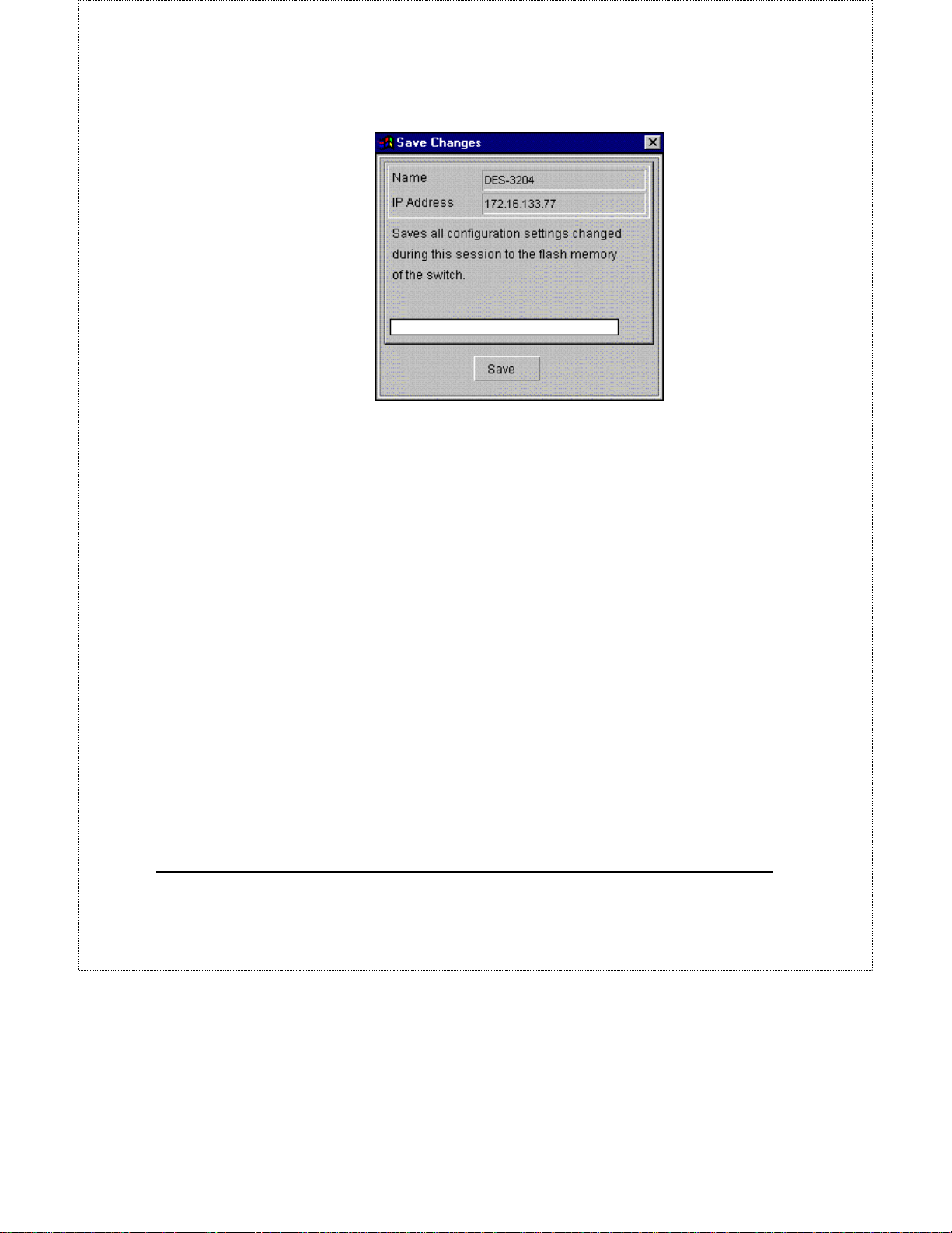
Save Changes
When configurat i on settings are cha nged using the Apply button in the various
windows, the changes will take effect until the switch is reset or powered off.
Using the Save Changes feature writes the settings onto flash memory in the
switch thereby becoming the new default settings. Settings stored in flash
memory are impervious to system resets or loss of power.
To save changes,
1. Click on the Reset menu button.
2. Select Save Changes from the drop-down menu.
DGS-3204 Management 41
Page 44
DGS-3204 Ethernet Switch Management User’s Guide
Click Save to save all changes made to configuration settings in the switch.
Reset
The management module allows you to reset the switch remotely. Doing a reset
is equivalent to turning the switch off and on again, which resets all statistic
counters and restores settings to the values stored in flash memory.
To perform a reset,
1.
Click on the Reset menu button.
2.
Choose Reset from the drop-down menu.
42 DGS-3204 Management
Page 45
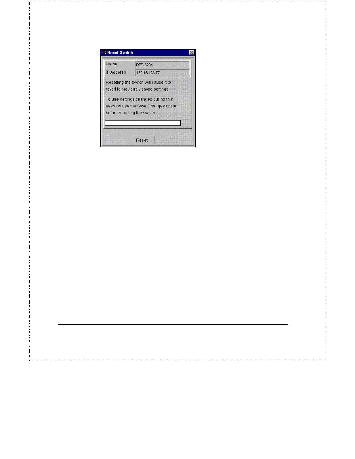
Click Reset to initiate a system reset.
DGS-3204 Ethernet Switch Management User’s Guide
DGS-3204 Management 43
Page 46

DGS-3204 Ethernet Switch Management User’s Guide
Index
A
Add MAC Static Forwarding Table
Entry........................................ 29
Add/Modify a device on the map7,
24
Admin State.......................... 16, 22
Advanced....................................20
agent............................................. 2
B
Block.......................................... 23
Boot Protocol ............................. 14
Boot Server Address .................. 14
broadcast packets ....................... 23
Broadcast Rx.............................. 35
Broadcast Storm Falling Action. 23
Broadcast Storm Rising Action.. 23
Broadcast Tx.............................. 35
C
Changing the IP settings............. 26
Collisions.................................... 34
Community................................. 27
configuration file........................ 19
Configuration File...................... 20
Configuration File Update.......... 20
Configuration Filename.............. 14
Configuration Menu Button ....... 11
Console....................................... 18
CRC Error .................................. 33
D
Default Gateway IP.....................25
Destination and Source...............31
Dropped Frames..........................34
E
Enable BootP On Startup............20
Entry Status.................................27
Error Status Line.........................10
Errors ..........................................32
F
Filter Conditions.........................31
Filtering Table.............................30
firmware......................................19
Firmware File..............................20
Firmware File Update.................20
Firmware Filename .....................14
Flow Control State................16, 22
Forward.......................................23
Fragments....................................34
Frames1024~1518Bytes..............35
Frames128~255Bytes..................35
Frames256~511Bytes..................35
Frames512~1023Bytes................35
Frames64Bytes............................34
Frames65~127Bytes....................34
Full..............................................10
full-duplex...................................10
44 Index
Page 47

DGS-3204 Ethernet Switch Management User’s Guide
G
General....................................... 18
Good Bytes Received (Bytes Rx)33
Good Bytes Sent (Bytes Tx)....... 33
Good Frames Received (Frames
Rx) .......................................... 33
Good Frames Sent (Frames Tx) . 33
H
Head Of Line (HOL) Blocking
Prevention............................... 21
Head-of Line blocking................ 23
HOL State....................... 15, 17, 23
I
IF Index...................................... 25
If Type........................................ 25
Information................................. 11
IP Address.................................. 25
IP Interfaces ............................... 24
J
Jabber......................................... 34
L
Last Boot Server address............ 14
Late Collision............................. 34
Link............................................ 10
Link Status..................................16
Link Status Alarm State.............. 16
Lock Address Table............. 15, 21
Lock State............................. 16, 22
M
MAC Address.......................30, 31
MAC Address Entry Expire Time
(sec)......................................... 21
Manager IP Address................... 27
map............................................... 7
Menu Buttons..........................9, 11
Mgmt Hardware Revision...........13
Mgmt Protocol............................13
MIB Capability Table.................24
module display..............................9
modules.........................................3
Monitor Menu Button.................32
Multicast Rx................................35
Multicast Tx................................35
N
Net Mask..................................... 25
network map..................................7
network performance ..................23
Number of IP Supported.............13
O
Out-Of-Band Baud Rate..............14
Out-of-band Rate.........................19
Oversize Frames..........................33
P
Packet Analysis.....................32, 40
Phys Address...............................25
Physical (MAC) Address ............13
platform.........................................3
Port..............................................30
Port Configuration ......................21
Port Errors...................................38
Port Information..........................15
Port Mirroring.............................28
Port Statistics ........................32, 35
Port Status Indicators..................10
Port Traffic..................................36
Port Utilization......................32, 35
Priority..................................17, 22
Prom Firmware Version..............13
2 Index
Page 48

DGS-3204 Ethernet Switch Management User’s Guide
R
Requirements................................ 4
Reset........................................... 43
Reset Menu Button..................... 42
RS232 Port Used As...................14
RS-232 Port Used As................. 19
Runtime Software Version......... 13
S
Save Changes............................. 42
Send Authentication Fail Trap....18
Servers........................................ 19
Set Configuration....................... 17
Set IP Interfaces ......................... 25
SNMP........................................... 3
Snmp Authentication.................. 13
SNMP community name ............ 27
SNMP traps................................ 26
Software Update Mode.........14, 20
Source Port................................. 28
Spanning Tree............................ 23
Spanning Tree Protocol........ 15, 21
Speed/Duplex............................. 16
Static Forwarding Table............. 29
Static Fwd Table ........................ 29
Statistics Collected by the Switch33
STP State .............................. 17, 23
Switch Configuration .................. 17
Switch Information......................11
SysContact..................................13
SysDescr .....................................12
SysLocation.................................13
SysName.....................................13
SysOID........................................12
SysUpTime .................................13
T
Target Port..................................28
TCP/IP settings.............................6
TFTP Server................................20
Total Bytes Received (Total Bytes
Rx)...........................................33
Total Frames Rx..........................33
Traffic.........................................32
Trap Receivers............................26
Trap Recipient.............................23
trap recipients..............................26
Type............................................16
U
Unauth packet community...........15
Unauth SNMP Packet IP.............14
Undersized Frames......................34
utilization....................................23
Utilization ...................................33
Index 3
 Loading...