

Page 1
D-Link SecuriCam
DCS-5300
Internet Camera
Manual
Version 1.00
Building Networks for People
Page 2

Contents
Contents of Package ............................................................................ 3
Introduction............................................................................................4
Features and Benefits ...........................................................................4
Connections ..........................................................................................6
Hardware Installation ............................................................................. 9
Software Installation ............................................................................10
Enabling UPnP for Windows XP/ME ...................................................13
Installing IP surveillance Software ........................................................17
Testing the DCS-5300......................................................................... 21
Security ...............................................................................................22
Using and Configuring the DCS-5300 with a Router ............................23
Using the DCS-5300 with the Internet Browser ....................................29
Using IP surveillance Software ............................................................58
Monitor Program ......................................................................58
Playback Program.................................................................... 78
Firmware Upgrades ............................................................................ 93
Appendix ............................................................................................ 96
Frequently Asked Questions .....................................................96
How to PING Your IP Address ...................................................99
Reset and Restore .................................................................100
I/O Connector ......................................................................... 101
Technical Specifications ......................................................... 102
Contacting Technical Support ............................................................104
Time Zone Table ................................................................................105
Warranty and Registration ................................................................. 107
2
Page 3
Package Contents
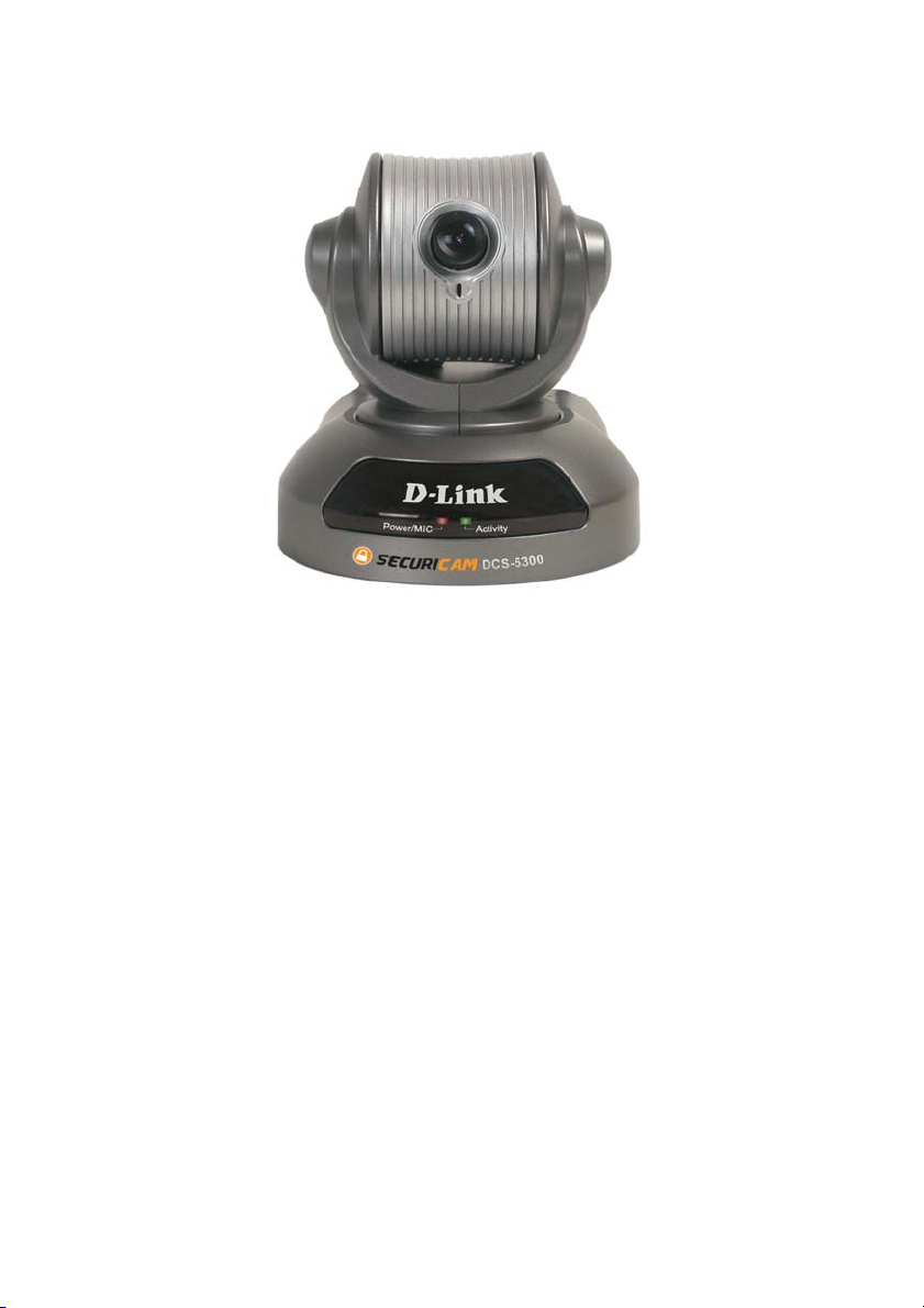
D-Link SecuriCam DCS-5300 Internet Camera
Power Adapter
Installation software and manual on CD
Quick Installation Guide
Camera Stand
Category 5 Ethernet Cable
Infrared Remote Control
If any of the above items are missing, please contact your reseller.
Note: Using a power supply with a different voltage than the one included with the
DCS-5300 will cause damage and void the warranty for this product.
Minimum System Requirements:
Internet Explorer 5.x or above Internet Web Browser
CPU: Pentium III, 800 MHz or above
Memory Size: 128 MB or above
VGA card resolution: 800 x 600 or above
3
Page 4

Introduction
The D-Link SecuriCam DCS-5300 Internet Camera is a full featured surveillance
system that connects to an Ethernet, Fast Ethernet or broadband Internet
connection to provide remote high-quality video and audio. The DCS-5300 is
the latest product added to the D-Link internet camera line. The camera features
a motorized pan and tilt function found on more expensive cameras. This
function allows the viewing area of the camera to extend 270o side-to-side and
90o up and down. The DCS-5300 gives you the ability to monitor your home/
office when you can not be there. Place the camera anywhere you would like to
monitor with no PC required on location!
Features and Benefits
The D-Link SecuriCam DCS-5300 Internet Camera is connected through an
Ethernet connection and a power source. You only need one PC to initially
configure multiple cameras for all locations. Each camera has a built in web
server with a configurable IP address.
Motorized Pan and Tilt Operation
The DCS-5300 has a pan and tilt function that can expand your viewing area to
cover a wide 270o angle side-to-side and a 90o angle up and down. This can be
controlled with a PC from any location or locally using the included infrared
remote control.
CCD Sensor
The DCS-5300 comes standard with a high quality CCD sensor that is superior
to a CMOS type sensor. The fixed focus glass lens will facilitate the use of the
DCS-5300 providing crystal clear and sharp images. You can view up to 30
frames per second of live motion video with 380 lines resolution.
Suports a Variety of Platforms
In addition , the DCS-5300 supports a variety of platforms including FTP, SMTP,
NTP, and HTTP. The camera also supports UPnP and DDNS. DDNS allows
the camera to use an easier to remember naming format rather than an IP
address. UPnP will allow users of Windows XP and ME to install the camera
with the click of a mouse.
4
Page 5

Features & Benefits (continued)
A/V Output
.
The SecuriCam DCS-5300 comes with an A/V output allowing you to connect
to your TV for local viewing. The DCS-5300 can also be connected to your
VCR to record activities directly to a VHS tape.
Surveillance Software
The surveillance software allows you to view up to 16 cameras simultaneously.
This software also allows controls to all 16 cameras by linking each one to its
own web page. Images can be monitored and recorded to a hard drive.
Internal/External Microphone
The SecuriCam DCS-5300 allows you to monitor video as well as audio through
the web browser. You have the option of using the DCS-5300’s integrated
microphone or your own external microphone using the connection located at
the rear of the unit.
5
Page 6
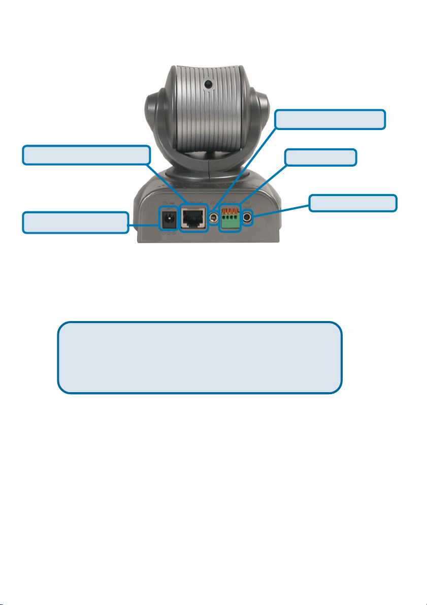
Connections
Microphone Connector
Ethernet Cable Connector
DC Power Connector
I/O Connector
AV Out Connector
Ethernet Cable Connector
The DCS-5300 back panel features an RJ-45 connector for connections to
10Base-T Ethernet cabling or 100Base-TX Fast Ethernet cabling. This network
port supports the NWay protocol, allowing the Internet Camera to automatically
detect or negotiate the transmission speed of the network.
The Ethernet cable included with the DCS-5300 Internet
Camera is a Category 5 “straight through” cable. This is
the recommended cable type when the camera is
connected to a 100 Mbps Fast Ethernet network hub or
switch.
DC Power Connector
The DC power input connector is located on the DCS-5300 Internet Camera’s
back panel and is labeled DC 12V with a single socket to supply power to the
Internet Camera.
Microphone
The DCS-5300 Internet Camera’s has an internal microphone. However, you
have the option of using an external microphone by plugging it into the
microphone connector.
AV Out
Plug the included A/V cable into the A/V out connector to use the DCS-5300
with a television or VCR.
6
Page 7
Connections (continued)
I/O Connector
The DCS-5300 provides a terminal block with two pairs of connectors situated
on the back panel. One pair is for input and the other is for output. The I/O
connectors provide th sical interface to send and receive digital signals to a
variety of external alarm devices. Please refer to the appendix in this manual
for detailed information.
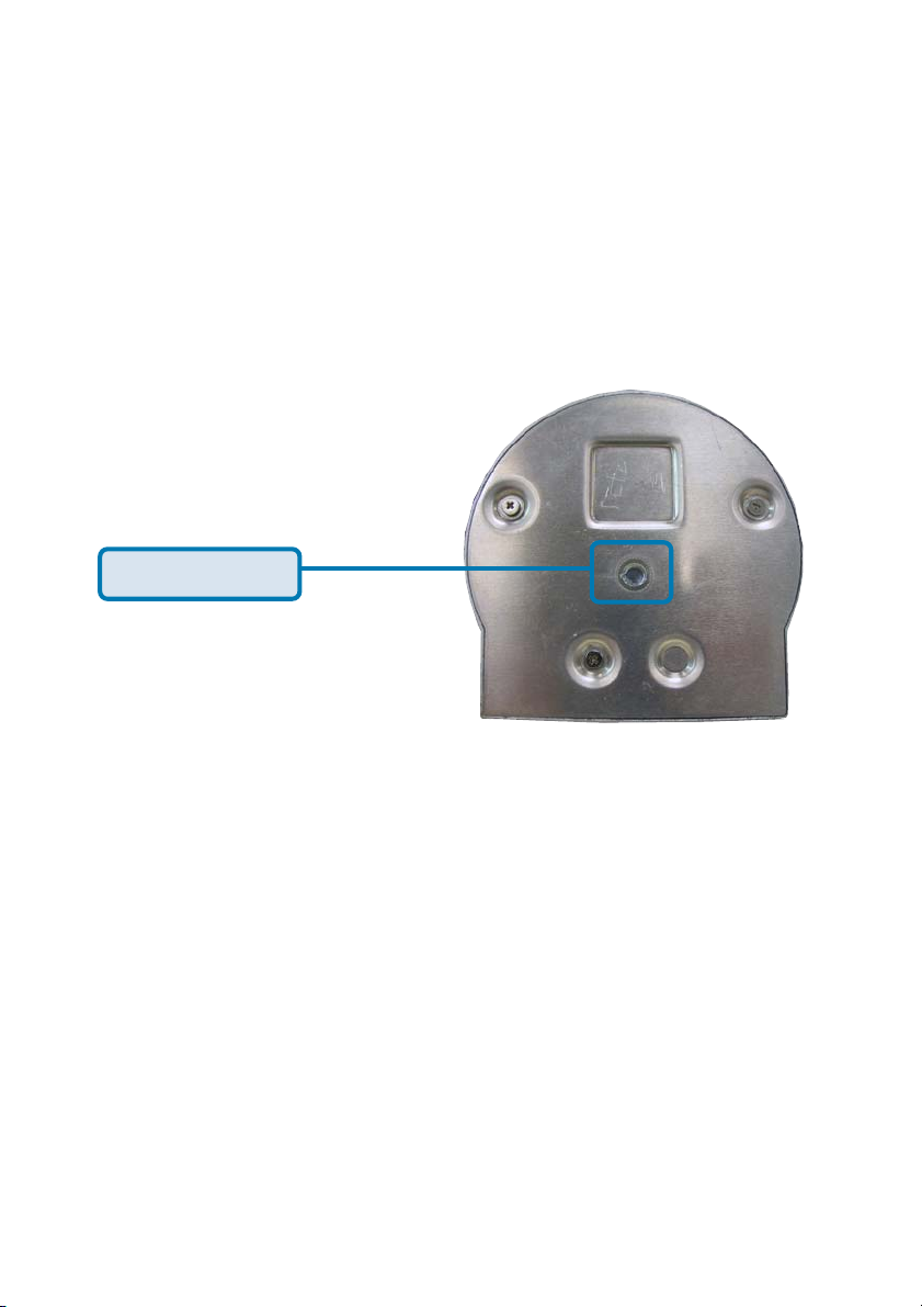
Bottom Panel
Socket for stand
Attachment socket for the Camera Stand
Located on the bottom panel of the DCS-5300, the socket is used to connect
the camera stand to the Internet Camera by attaching the screw head on the
camera stand to the Internet Camera.
Power LED
LED stands for Light-Emitting Diode.
The Power LED is positioned on the right side of the Internet Camera lens. As
soon as the power adapter is connected to the Internet camera the power LED
will flash red and green several times, the DCS-5300 is conducting a
self-test. Upon passing the self-test the LED will turn green to indicate a good
connection to an Ethernet port or red to indicate no connection has been made.
7
Page 8
Connections (continued)
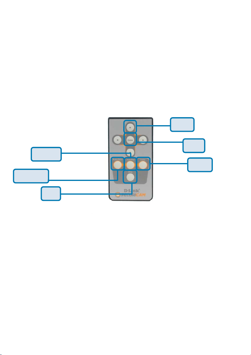
Infrared Remote Control
Included with the DCS-5300 is an infrared remote control. You have the option
of controlling the camera via the Pan/Tilt Controls using the IP surveillance
software or via the infrared remote. To use the remote, make sure that IR Control
is enabled on the Camera Control page in the Configuration Menu under
Advanced. Please refer to the section titled “Using the DCS-5300 with
an Internet Browser” in this manual for more information.
Arrows
Home
Auto-Pan
Center
Auto-Patrol
Stop
Arrows -
Home- Returns the camera lens to the set home position.
Auto-Patrol-
Auto-Pan-
Center-
Stop-
Use the Up,Down, Left and Right arrows to tilt/
navigate the camera lens.
Enables the Auto-Patrol function.
Pans the camera one full cycle.
Centers the camera lens.
Stops the movement of the camera during pan.
8
Page 9
Hardware Installation
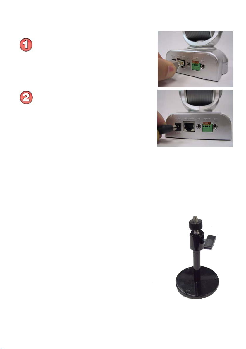
Connect an Ethernet cable
Connect an Ethernet cable to the network
cable connector located on the DCS-5300’s
back panel and attach it to the network.
Attach the external power supply
Attach the external power supply to the DC
power input connector located on the
DCS-5300’s back panel labeled 12VCD
and connect the other end to your wall outlet.
When you have a proper connection, the LED will turn from red to green. The
light may cycle on and off and your computer may show an intermittent loss of
connectivity, this is normal until you have configured your Internet Camera.
Attaching the Internet Camera to the Camera Stand
The Internet Camera comes with a camera
stand with a swivel ball screw head that
can be attached to the Internet Camera
bottom socket cavity. Attach the camera
stand to the Internet Camera and station it
for your application. There are holes
located in the base of the camera stand
allowing the Internet Camera to be mounted
to the ceiling, or any wall securely.
9
Page 10

Software Installation
After you have successfully completed the hardware installation of the
DCS-5300 Internet Camera, it is necessary to install software to configure and
operate the camera. The first step is to run the IP Installer program on the CD.
IP Installer allows you to use the Internet Camera with your Internet browser.
With the IP Installer program you can enter settings that permit the camera to
access the Internet directly or through your Ethernet network.
After the IP Installer software program is completed, you will have an operating
and controllable Internet Camera. From your Internet Explorer Web browser
you will be able to access the video and sound from the Internet camera. The
camera has a built-in Web server. This Web server will allow the camera to
access the Internet without being attached to a computer and permits users to
view the video and audio remotely.
After running the IP Installer, you will be able to operate the DCS-5300 and
view the camera remotely through Internet Explorer 5.x and above.
However it is necessary to install the IP surveillance software from the enclosed
CD to create a truly powerful monitoring and surveillance system. The following
section will show in detail the installation of the IP Installer and the IP
surveillance software.
Installing the IP Installer program
Insert the CD that is included with the DCS-5300 Internet Camera. The
DCS-5300 installation menu will start up automatically from the CD. If the CD
does not startup automatically (the Windows operating system may turn this
function off), access the CD from Windows and click on the autorun.exe program
to access the installation menu shown below:
Click IP Installer
10
Page 11
Software Installation (continued)
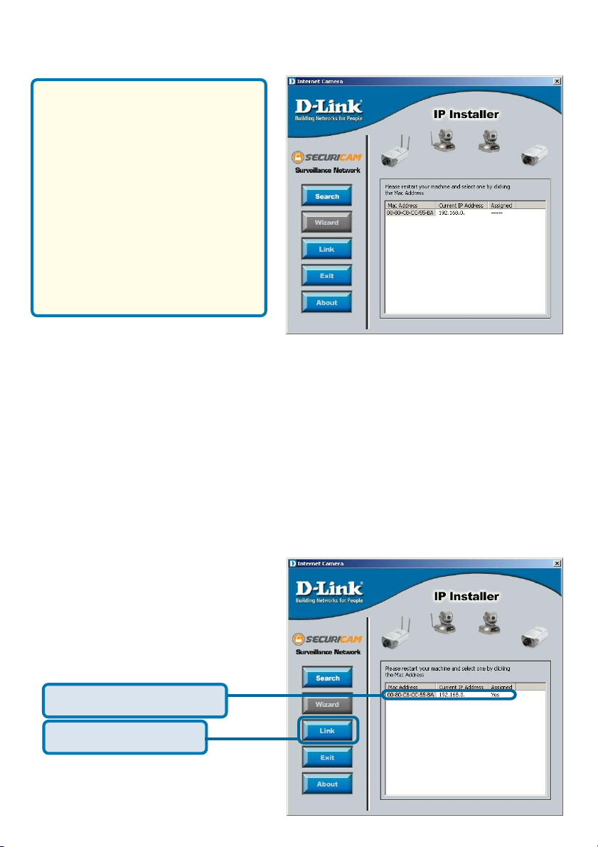
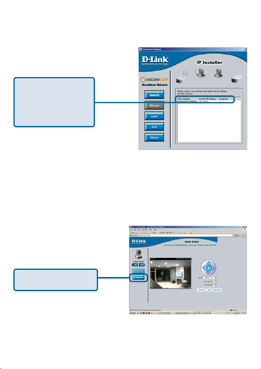
The opening IP Installer screen will
appear and show a MAC address
of the DCS-5300 and an IP Address
(which may or may not be correct
depending on what you have your
DCS-5300 connected to.) If you
have a DHCP* server on your
network, there will be a valid IP
Address displayed here.
*A DHCP server is a device that
supplies IP Addresses to its clients
that are on the same network.
IMPORTANT:
A hardware reset of the Internet Camera is now required to allow the IP Installer
program to configure the camera correctly. To accomplish this reset, lightly insert
a paper clip (or a similar sized tool) into the reset hole on the back of the camera
(see page 6 for the location of the reset hole.) The LED on the front of the
camera will begin blinking red and green. When it stops the blinking cycle continue
to hold in the reset button until a second cycle of blinking red and green lights
indicates a second reset cycle has completed. This will take approximately 5-7
seconds.
146
The IP Installer will now show a MAC address for the DCS-5300 and an IP
address. This IP address may not be correct at this step in the installation.
Highlight the MAC address
Click on the Link button
11
146
Page 12
Software Installation (continued)
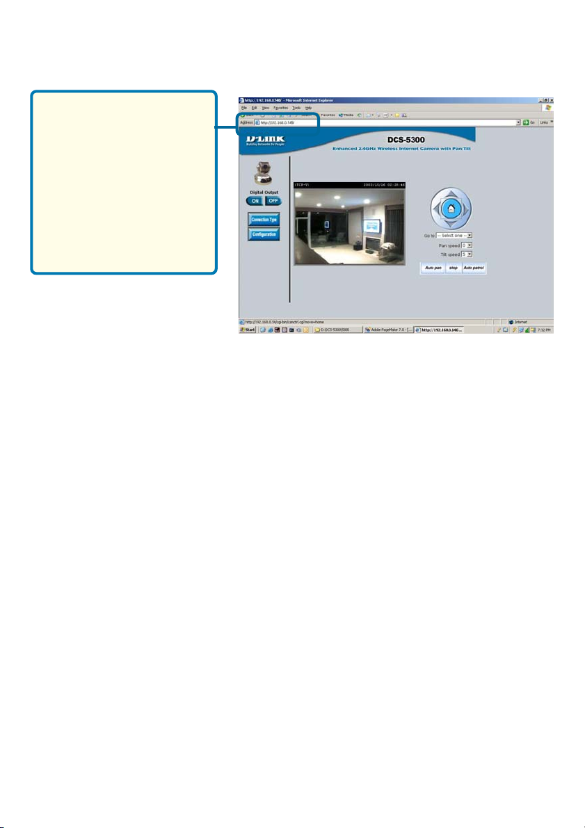
After you click on the Link
button, IP Installer will
automatically open your
Internet browser to the IP
Address of the DCS-
5300. In this example, it is:
http://192.168.0.146. Your
DCS-5300 may have a different IP Address.
You have now completed the Setup Wizard and are ready to use your
camera! You can also continue to the section titled “Installing IP surveillance Software” to install the IP surveillance software before you begin
to use the DCS-5300.
12
Page 13
Enabling UPnP for Windows XP/ME
UPnP is short for Universal Plug and Play, which is a networking architecture
that provides compatibility among networking equipment, software, and
peripherals. The DCS-5300 is a UPnP enabled internet camera. If your operating
system is UPnP enabled, the device will be easier to configure. If you do not
want to use the UPnP functionality, it can be disabled by unselecting “Enabled”
on the DDNS/UPnP settings page under “Advanced” in the configuration menu.
Use the following steps to enable UPnP (Universal Plug and Play) settings only
if you are running Windows XP/ME. If you are running Windows 98/2000, UPnP
is not available by industry standards.
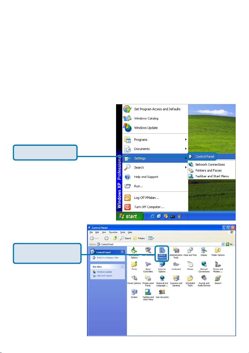
Go to Start >Settings.
Click Control Panel
Click Add or Remove
Programs
13
Page 14
Enabling UPnP for Windows XP/ME
(continued)
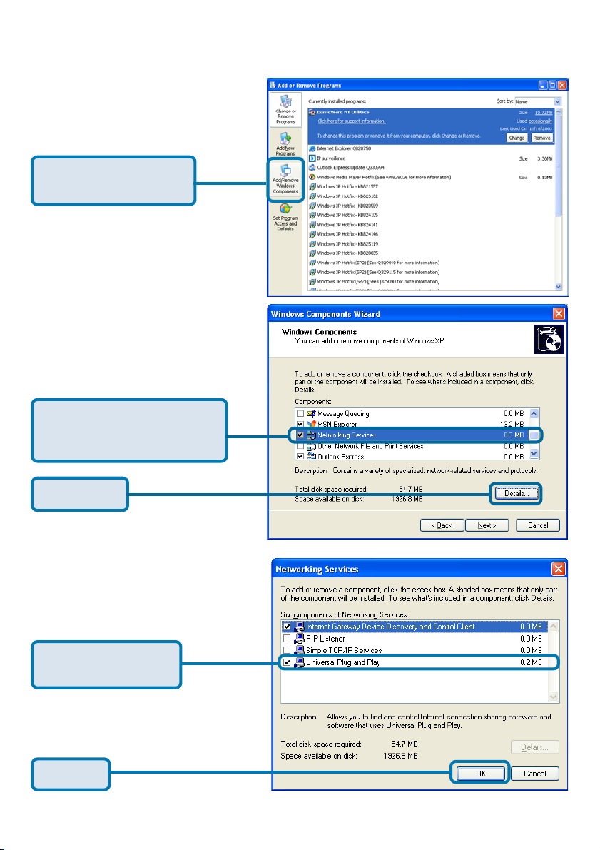
Click Add/Remove
Windows Components
The following screen will
appear:
Select Networking Services
(Communications in Windows
ME)
Click Details
Select Universal
Plug and Play
Click Ok
14
Page 15
Enabling UPnP for Windows XP/ME
(continued)
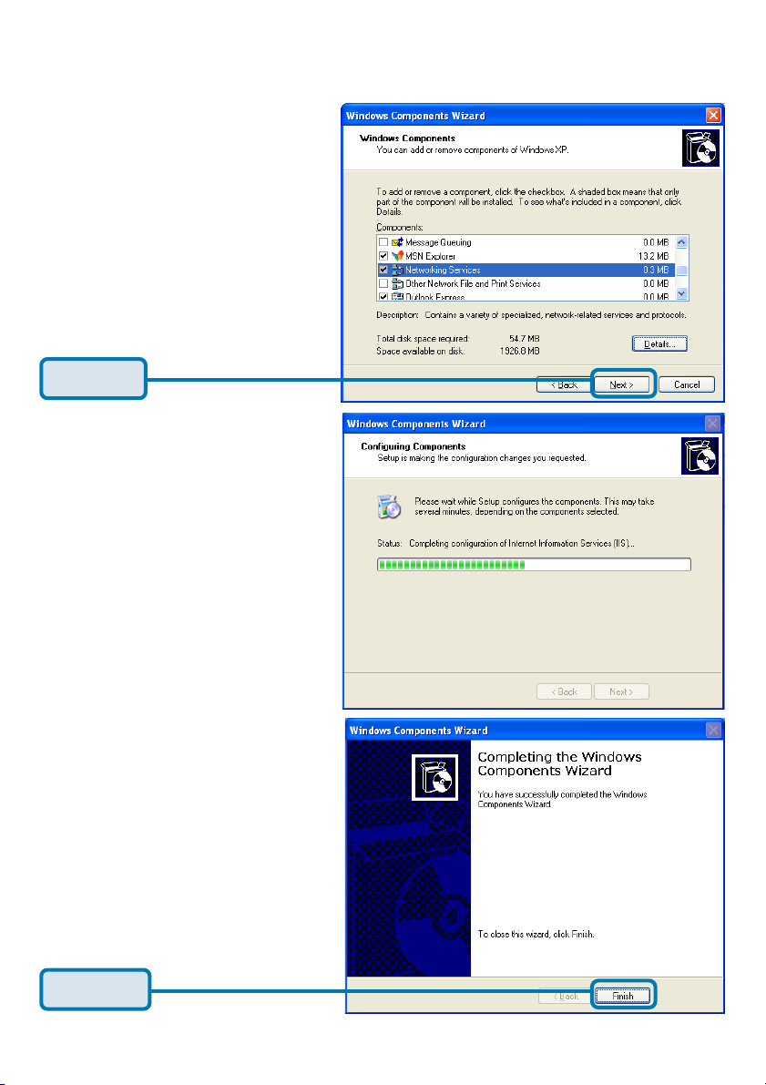
Click Next
Please wait while Setup
configures the components.
Click Finish
15
Page 16
Enabling UPnP for Windows XP/ME
(continued)
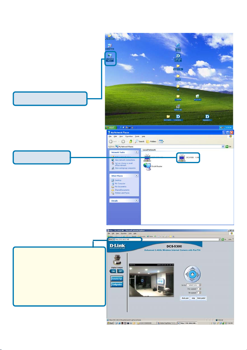
To view your DCS-5300
Internet Camera in an
Internet browser, go to your
Desktop and click My
Network Places.
Click My Network Places
Click DCS-5300-146
The last three digits (146),
represent the fourth octet of your
Internet Camera’s IP address
(in this example, 198.168.0.146).
After you click on the DCS-5300-
146 icon, your Internet browser
will automatically be opened to
the IP Address of the DCS-5300,
in this example it is: http://
192.168.0.146. Your DCS-5300
may have a different IP Address.
(Note: Screen shots are taken in Windows XP, similar screens will appear in Windows ME.)
16
Page 17
Installing IP surveillance Software
The IP surveillance Software on the CD included with the DCS-5300 Internet
Camera converts the DCS-5300 into a powerful, yet flexible, surveillance system
for home or business, with these features:
Real-time Monitoring
Video Recording to hard disk
High quality video
High compression ratio
Maximum of 16 cameras with different monitor layouts
Smart playback
Triggered event browsing
Fast database searching
Cofigurable automated alarms
Account password protection
Scheduled recording for each camera
Email / FTP snapshot
AVI file export
Motion detection for each camera
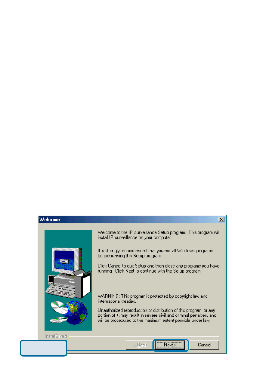
To install the IP surveillance software, click on Install IP surveillance Software
on the CD included with the Internet Camera. The Welcome screen appears:
Click Next
17
Page 18
Installing IP surveillance Software (continued)
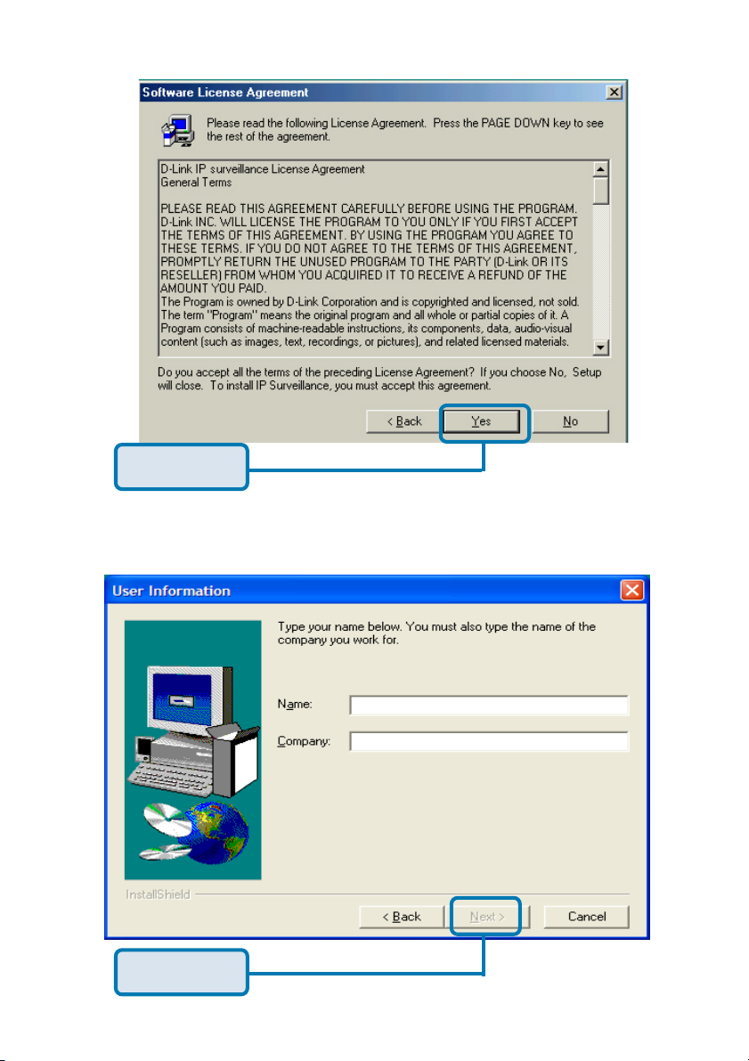
Click Yes
Please read the Software Licensing Agreement and click yes if you agree with
the agreement. Click “No” to exit the installation.
Click Next
Enter your name and company information and click “Next”.
18
Page 19
Installing IP surveillance Software (continued)
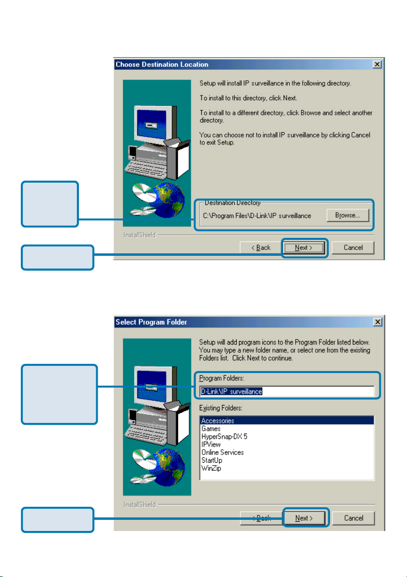
Select the
destination
directory.
Click Next
Select the
program folder
the software will
be installed into.
Click Next
19
Page 20
Installing IP surveillance Software (continued)
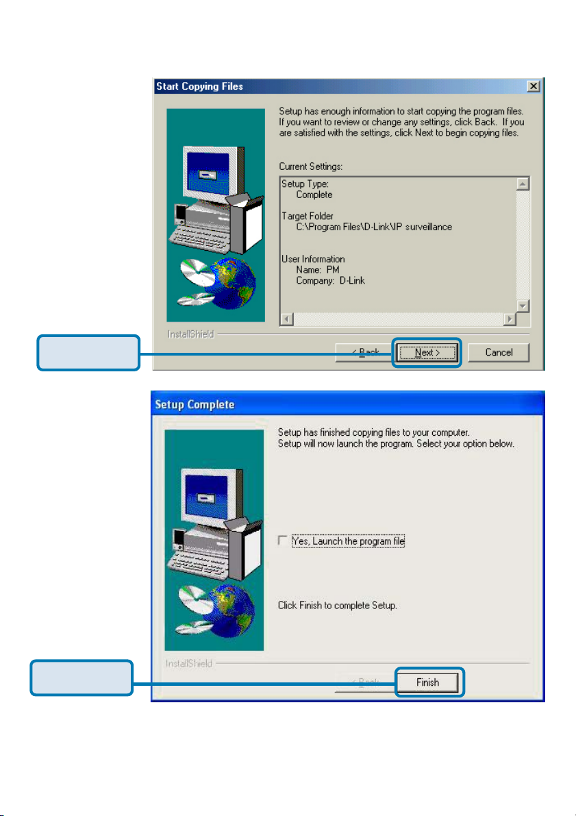
Click Next
Click Finish
The installation is complete.
20
Page 21
Testing the DCS-5300 Internet Camera
Open your Internet browser
and type in the IP address
of the DCS-5300. In this
example the address is:
http://192.168.0.146 (your
DCS-5300 may have a
different IP address based
on what you used in the
IP Installer program.)
The window in the center of your browser is the camera image window. You
should now see a video image and hear the audio over your computer speakers
from the DCS-5300. If you are having problems please consult the FAQ section
of this manual.
21
Page 22
Security
At this point it is highly recommended that you click on the Configuration button
on the Home screen, and then the Tools tab to bring you to the Admin screen.
Enter a password for security purposes.
To ensure the highest security and prevent unauthorized use of the Internet
Camera, the Administrator has the exclusive privilege to access the System
Administration settings to allow users entry and authorize privileges for all
users. The Internet Camera supports multi-level password protection/access
to the Internet Camera that can be restricted to defined users who have a User
Name and User Password, which is assigned by the Administrator.
The Administrator can release a public user name and password so that when
remote users access the Internet Camera they will have the right to view the
image transmitted by the Internet Camera.
When the Internet Camera is used for the first time, it is highly
recommended that the Administrator set the Administrator Password
to constrain user access to the Internet Camera since the Default
settings are Null String (no password). Once the Password is defined,
only the Administrator has access to the management of the Internet
Camera. This procedure should be done as soon as possible since the
security features of the Internet Camera will not be enabled until the
Administrator Password is defined.
22
Page 23

Configuring a DCS-5300 Behind a NAT Router or Internet Gateway
D-Link’s DCS-5300 is a versatile and cost effective Internet Camera offering
both video and audio monitoring. It can also serve as a powerful surveillance
system in security applications. The DCS-5300 can be used with any wired or
wireless router. This section explains how to view the camera from either the
Internet or from inside your internal network.
Materials Needed:
• 1 DCS-5300 Internet Camera
• 1 Ethernet Cable
• A Wired or Wireless router such as the D-Link DI-614+ Wireless Router
• Ethernet based PC for system configuration
SETTING UP THE DCS-5300 FOR USE BEHIND A ROUTER
Installing a DCS-5300 Internet Camera on your network is an easy 4–step
procedure:
Assign a local IP Address to your Internet Camera
View the Internet Camera Using Your Internet Explorer Web browser
Access the Router on Your Web browser
Open Virtual Server Ports for Your Router (Enable Remote Viewing)
This section is designed to walk you through the setup process for installing
your camera behind a router and enable remote video viewing. For the basic
setup of the DCS-5300, follow the steps outlined in the Quick Installation
Guide.
After you have completed the setup of the DCS-5300 outlined in the Quick
Installation Guide you will have an operating camera that has an assigned IP
Address. Because you are using a router to share the Internet with one or more
PCs, the IP Address assigned to the Internet Camera will be a local IP Address.
This allows viewing within your Local Area Network (LAN) until the router is
configured to allow remote viewing of the camera over the Internet.
Assign a Local IP Address for Your Camera
Run the IP Installer program from the CD included with the DCS-5300. Follow
the steps in the Quick Installation Guide to configure the DCS-5300. The
camera will be assigned a local IP Address that allows it to be recognized by
the router. Write down this IP Address for future reference.
23
Page 24
Using & Configuring the DCS-5300 with a
NAT Router (continued)
This is the IP Address
assigned to your camera.
Write it down for later use.
192.168.0.146 is only an
example. You will probably
have a different IP Address.
Assign a Local IP Address with IP Installer
View the Internet Camera using your Internet Explorer Web
browser
Run your Internet Explorer Web browser. In the address bar, type in the IP
Address that was assigned to the Internet Camera by the IP Installer program.
The DCS-5300 Home Page appears with a window displaying live video from
the camera. You are able to view this screen from any PC running Internet
Explorer on your LAN.
146
Click on the Configuration
button.
Viewing the Video on the browser to test the connection
Click on the Configuration button on the left side of the display. Scroll to the
bottom of the Network Configuration page to display the ports used by HTTP
and Streaming audio and video.
24
Page 25
Using & Configuring the DCS-5300 with a
NAT Router (continued)
These are the port settings for
your camera.They can be
changed if needed.
Ports that are used by the DCS-5300
Router Set-Up and Installation
The following steps generally apply to any router that you have on your network.
The D-Link DI-614+ is used as an example to clarify the configuration process.
Configure the initial settings of the DI-614+ by following the steps outlined in the
DI-614+ Quick Installation Guide.
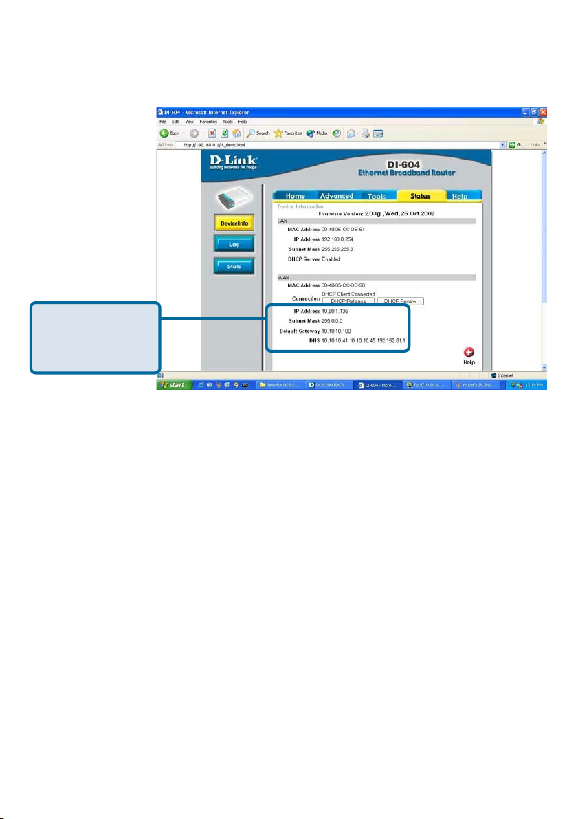
Access Your Router on Your Web Browser
If you have cable or DSL service, you will most likely have a dynamically assigned
WAN IP Address. ‘Dynamic’ means that your router’s IP address can change
from time to time depending on your ISP. A dynamic WAN IP Address identifies
your router on the public network and allows it to access the Internet. To find
out what your router’s WAN IP Address is, go to the Status menu on your router
and locate the WAN information for your router. As shown on the next page the
WAN IP Address will be listed. This will be the address that you will need to
type in your web browser to view your camera over the Internet.
25
Page 26
Using & Configuring the DCS-5300 with a
NAT Router (continued)
Your WAN IP
Address will be
listed here.
Determine Your Router’s IP Address (WAN)
Note: Because a dynamic WAN IP can change from time to time depending on
your ISP, you may want to obtain a Static IP address from your ISP. A Static IP
address is a fixed IP address that will not change over time and will be more
convenient for you to use to access your camera from a remote location. The
Static IP Address will also allow you to access your camera attached to your
router over the Internet
Open Virtual Server Ports to Enable Remote Image Viewing
The firewall security features built into the DI-614+ router prevent users from
accessing the video from the DCS-5300 over the Internet. The router connects
to the Internet over a series of numbered ports. The ports normally used by the
DCS-5300 are blocked from access over the Internet. Therefore, these ports
need to be made accessible over the Internet. This is accomplished using the
Virtual Server function on the DI-614+ router. The Virtual Server ports used
by the camera must be opened through the router for remote access to your
camera. Virtual Server is accessed by clicking on the Advanced tab of the
router screen.
26
Page 27
Using & Configuring the DCS-5300 with a
NAT Router (continued)
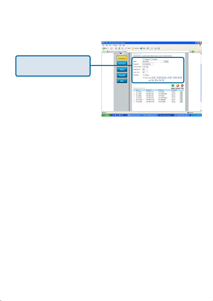
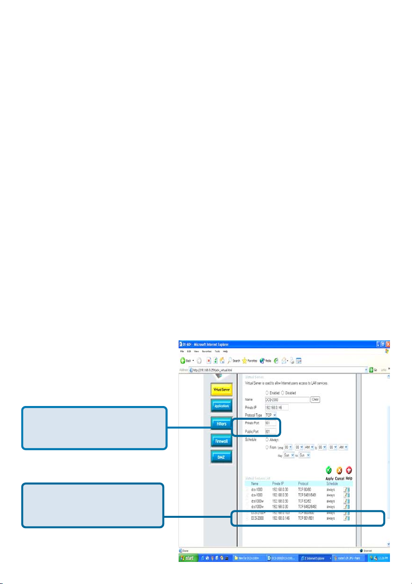
Follow these steps to configure your router’s Virtual Server settings:
• Click Enabled.
• Select Both under Protocol Type (TCP and UDP)
• Enter your camera’s local IP Address (e.g., 192.168.0.146 in
the example in step
• If you are using the default camera port settings, enter 80 in to
the Public and Private Port section, click Apply.
• Scheduling should be set to Always so that the camera
images can be accessed at any time.
Repeat the above steps adding ports 5001, 5002 and 5003 to both the Public
and Private Port sections. A check mark appearing before the camera name
will indicate that the ports are enabled.
Important: Some ISPs block access to port 80. Be sure to check with your ISP
so that you can open the appropriate ports accordingly. Some ISPs block traffic
on commonly used ports to conserve bandwidth. If your ISP does not pass
traffic on port 80, you will need to change the port the camera uses from 80 to
something else, such as 800. Not all routers are the same, so refer to your user
manual for specific instructions on how to open ports.
above) in the Private IP field.
Enter valid ports in the Virtual
Servers section of your router
Please make sure to check
the box on this line to
enable settings
27
Page 28
Viewing Your Camera
After all settings have been entered correctly, a PC user inside or outside your
network will have access to the camera through the Internet Explorer Web
browser. To access the camera from the Internet, type the IP Address of the
router given to you by your ISP, followed by a colon, and the port number that
you gave your camera (e.g., http://205.163.122.96:83). It is not necessary to
enter the colon and port number if you are using the default Web server port 80.
To access from a computer on your local (home) network, simply enter the local
IP Address of the Camera. (e.g., 192.168.0.146).
http://205.163.122.96:83
Viewing the DCS-5300 Remotely
28
Page 29
Using the DCS-5300 with an Internet browser
If you are following this manual in the order it is presented, you should now have
an operating DCS-5300 Internet Camera configured with the Installer program.
You also have installed the IP surveillance software from the CD. This section
of the manual will deal with using the Internet Camera in two parts:
Using the DCS-5300 with an Internet browser and accessing
the screens to control and monitor the camera.
Using the IP surveillance software with the DCS-5300.
Open your Internet Explorer Web browser and enter the IP address for your
Internet Camera.
In the example, this address is 192.168.0.146. Your address may differ.
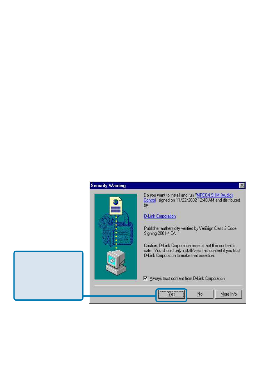
If a window appears
asking to install a
Verisign certificate
for authentication
Click Yes.
29
Page 30
Using the DCS-5300 with an Internet browser
(continued)
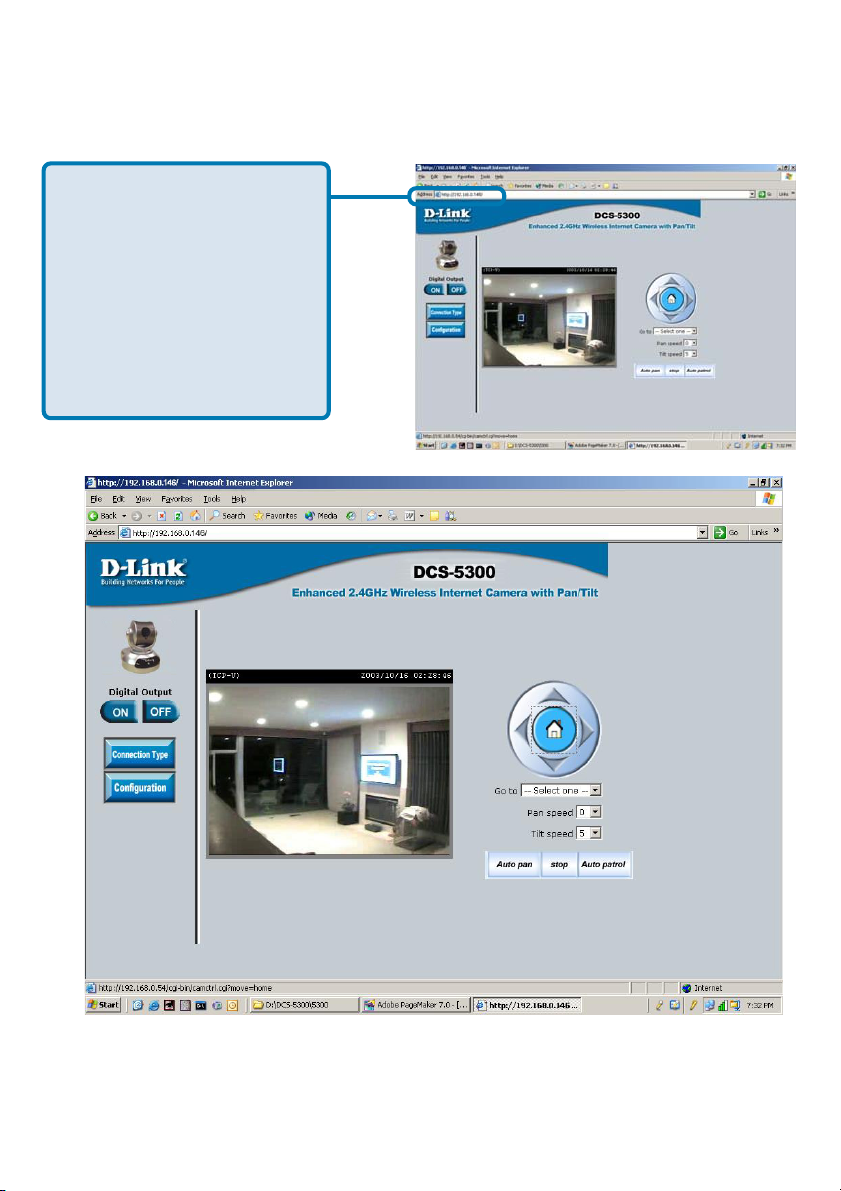
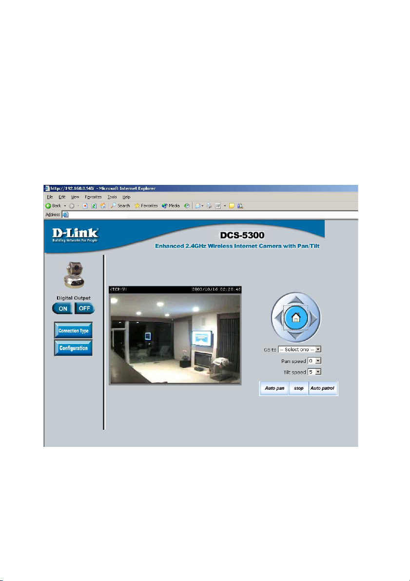
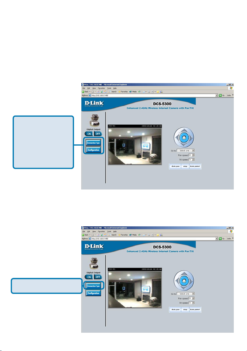
Home Page Screen
The image from the DCS-5300 should be visible from the Home page on your
computer monitor.
There are two
buttons on the left
side of the Home
page:
Connection Type
and Configuration.
Click on the Connection Type button to change settings related to the
connection.
Click Connection Type
30
Page 31

Using the DCS-5300 with an Internet browser
(continued)
Home > Connections Screen
The following options are available from the Connections settings screen:
Media Option:
Option for users to disable or enable audio when viewing video.
Protocol Option
The UDP Protocol should be chosen for the most users. Generally the client
computer will automatically try these protocols in the following order,
UDP -> TCP -> HTTP.
After the client connects to the DCS-5300 successfully, the working protocol
will be displayed in “Protocol Option”. The chosen protocol will be recorded in
the user’s PC and used for the next connection. If the network environment is
changed or users want to let the web browser automatically detect the protocol,
select UDP manually and click Save to change the setting and return Home to
reconnect with the new setting.
Options:
UDP Protocol - Offers the highest image and video quality.However,
packet losses will diminish image quality when bandwidth becomes
restricted.
TCP Protocol - Packet loss is less likely to occur compared to UDP
when bandwidth is restricted.
HTTP Protocol - If the network is protected by a firewall and it opens
HTTP port (80) only, HTTP protocol must be selected. In this mode,
audio is disabled and only video can be viewed.
Click the Home tab to return to the DCS-5300 Home page.
31
Page 32

Using the DCS-5300 with an Internet browser
(continued)
Home > Configuration
Click on the Configuration button on the Home page:
Click Configuration
There are 5 tabs across the top of the Configuration screen.From each tab,
different elements of the DCS-5300 can be configured. The Advanced tab is
the default screen in Configuration and Network is the default screen under
Advanced.
Any changes made to these settings will
require the system to restart to validate.
Make sure every field is correctly typed
before clicking on Apply.
32
Page 33

Using the DCS-5300 with an Internet browser
(continued)
Configuration > Advanced > Network
Reset IP Address at next boot
Once the DCS-5300 is configured, this box should be unchecked at all times. If
the box has been checked and the connection is lost, either run IP Installer or
PING the IP Address of the camera from a command prompt to regain the
connection.
General Settings
IP address - Necessary for network identification.
Subnet mask - Used to determine if the destination is in the same
subnet. The default value is “255.255.255.0.”
Default router - The router used to forward frames to destinations
in a different subnet. Invalid router settings may
cause the failure of transmissions to a different
subnet.
Primary DNS - Primary domain name server that translates
names to IP addresses.
Secondary DNS - Secondary domain name server to backup the
primary one.
HTTP Settings
HTTP Port-
Can be set to other than the default port 80. When
the administrator changes the HTTP port of the
DCS-5300 (which has an IP address of
192.168.0.146) from 80 to 8080, users must type
http://192.168.0.100:8080 in the Web browser
bar.
33
Page 34

Using the DCS-5300 with an Internet browser
(continued)
Configuration > Advanced >Network Settings (continued)
Streaming Settings
Control channel port - It can be set to other than the default port 5001 to
correspond with the port opened by the firewall.
Audio channel port - It can be set to other than the default port 5002 to
correspond with the port opened by the firewall.
Video channel port - It can be set to other than the default port 5003 to
correspond with the port opened by the firewall.
Improve audio quality
in low bandwidth
environment - In a low bandwidth network environment you can
check this option to improve audio quality by
sacrificing some real-time synchronization.
WLAN Configuration Settings
SSID - (Service Set Identifier) is a name that identifies a
wireless network. Access Points and wireless
clients attempting to connect to a specific WLAN
(Wireless Local Area Network) must use the
same SSID. The default setting is default.
Wireless Mode- Click on the pull-down menu; select from the
following options:
Infrastructure - connecting the WLAN using an
Access Point such as the DWL-1000AP+. (The
default setting.)
Ad-Hoc – wireless mode used when connecting
directly to a computer equipped with a wireless
adapter in a peer-to-peer environment.
34
Page 35

Using the DCS-5300 with an Internet browser
(continued)
Configuration > Advanced >Network Settings (continued)
Channel - The default wireless channel setting is channel
6. Select the channel that is the same as the
other wireless devices on your network.
TX Rate- Select the transmission rate on the network.
22 Mbps is the default setting.
Preamble- Select Long or Short Preamble. The Preamble
defines the length of the CRC block (Cyclic
Redundancy Check is a common technique for
detecting data transmission errors) for
communication between the Access Point and
the roaming wireless Network adapters. Long
Preamble is the default setting. Note: High
network traffic areas should use the shorter
preamble type.
Data Encryption - Enable Encryption by clicking on the box. The
DCS-5300W has Encryption disabled as the
default setting.
Auth mode - Choose one of the following authorization
modes:
Open Authentication - Communicates the key across the network.
Shared Authentication - Allows communication only with other devices
with identical WEP settings.
Auto - Will automatically adjust to the Authentication
mode of the wireless client.
Key type - Select the key length, either 64, 128 or 256 bits.
Key Format - Select an ASCII or hexadecimal key format.
Key Index - You can create up to 4 different security keys.
Click Apply to make
changes effective
35
Page 36

Using the DCS-5300 with an Internet browser
(continued)
Configuration > Advanced > Mail & FTP
Click the Mail&FTP button from the Configuration screen to access video
settings that control sending images via email and FTP.
Click Mail & FTP
SMTP
SMTP (mail) server 1 - The domain name or IP address of an external
mail server.
Recipient email address 1 - The email address of recipients for snapshots or
a system log file. Multiple recipients must be
separated by a semicolon “;”
SMTP (mail) server 2 -
Recipient email address 2 -
Return email address -
The domain name or IP address of a secondary
mail server used if the primary mail server is
unreachable.
The email address of recipients for the secondary
server.
A return email address to use if the snapshot or
system log email fails to send.
36
Page 37

Using the DCS-5300 with an Internet browser
(continued)
Configuration > Advanced > Mail & FTP (Continued)
FTP Settings
Local FTP server port -
It can be other than default port 21. If you find that
you want to change the port to a port number
other than 21, you will need to specify the port
when connecting to the FTP server. For example
FTP://68.5.1.81:60 (if you are to use port 60 for
your FTP server port)
1st FTP server -
1st FTP user name -
1st FTP password -
1st FTP remote folder -
Primary FTP Passive
Mode-
The domain name or IP address of the external
FTP server. The following user settings must be
correctly configured for remote access.
Granted user name on the external FTP server.
Granted password on the external FTP server.
Granted folder on the external FTP server. The
string must conform to the external FTP server.
Some FTP servers cannot accept a preceding
slash symbol before the path if there is no virtual
path mapping. Refer to the instructions of the
external FTP server for details. The folder privilege
must be open for upload.
If the DCS-5300 is located inside a network that
is protected by a firewall, a data connection for
FTP may be prohibited. Passive mode FTP can
bypass this rule and allow the uploading of
snapshots. If the passive mode is selected, the
DCS-5300 can automatically attempt to upload
in active mode if the external FTP server does
not support passive mode.
37
Page 38

Using the DCS-5300 with an Internet browser
(continued)
Configuration > Advanced > Mail & FTP (Continued)
2nd FTP server - The domain name or IP address of the external
FTP server.
2nd FTP user name - Granted user name on the backup FTP server.
2nd FTP password - Granted password on the backup FTP server.
2nd FTP remote folder - Granted folder on the backup FTP server.
Secondary FTP passive
Mode - Passive mode setting for the backup FTP server.
Click Apply to make
changes effective
Invalid settings may cause the DCS-5300 to not respond. Change the
configuration settings only if necessary. Consult with your network
administrator or your Internet Service Provider (ISP) if you do not have the
necessary information. If you cannot connect to the camera, refer to page
97 for camera reset and restore factory settings procedures.
38
Page 39

Using the DCS-5300 with an Internet browser
(continued)
Configuration > Advanced > DDNS & UPnP
Click the DDNS & UPnP button from the Configuration screen to access
video settings that affect how the video image appears.
Click DNS & UPnP
Dynamic DNS (DDNS)
Dynamic DNS (Domain Name Service) is a method of keeping a domain name
linked to a changing (dynamic) IP address. With most Cable and DSL
connections, you are assigned a dynamic IP address and that address is used
only for the duration of that specific connection. With the DCS-5300, you can
setup your DDNS service and the DCS-5300 will automatically update your
DDNS server every time it receives a different IP address.
39
Page 40

Using the DCS-5300 with an Internet browser
(continued)
Configuration > Advanced > DDNS & UPnP (Continued)
Enable DDNS -
Provider- Select your Dynamic DNS provider from the pull
Host name-
Username/E-mail-
Password/Key-
Click to enable the DDNS function.
down menu.
Enter the host name of the DDNS server.
Enter your username or e-mail used to connect to
the DDNS server.
Enter your password or key used to connect to
the DDNS server.
UPnP
UPnP is short for Universal Plug and Play, which is a networking architecture
that provides compatibility among networking equipment, software, and
peripherals. The DCS-5300 is a UPnP enabled internet camera. If your operating
system is UPnP enabled, the device will be easier to configure. If you do not
want to use the UPnP functionality, it can be disabled by unselecting “Enabled”.
Click Apply to make
changes effective
40
Page 41

Using the DCS-5300 with an Internet browser
(continued)
Configuration > Advanced > Audio/Video
Click the Audio/Video button from the Configuration screen to access video
settings that affect how the video image appears.
Click Audio/Video
Audio Settings -
Audio Source- Select either an internal or external microphone as
Text on video -
Color -
Size -
Check the box to improve audio quality in a now
bandwidth environment.
the audio source. If you choose to use an external
microphone, connect it to the microphone
connection at the rear of the DCS-5300.
Text will be displayed in the black bar above the video
window with the timestamp. The timestamp is
captured from the date and time of the DCS-5300
and is maintained by a built-in real-time clock.
Select the option for color or monochrome video
display.
Three options exist for two sizes of video display:
Normal is the default video display mode.
Half is a quarter size of Normal.
41
Page 42

Using the DCS-5300 with an Internet browser
(continued)
Configuration > Advanced > Audio/Video (Continued)
Half x 2 has the same video size as Normal but
image quality is reduced and it consumes less
network bandwidth.
Power line frequency
(for fluorescent light)
Maximum frame rate-
Video quality control-
Flip - Vertically rotate the video.
Mirror - Horizontally rotate the video. Check both flip and
Fluorescent lights may intermittently flash depending
on the AC power line frequency. Change the
frequency setting to eliminate a flashing image when
the light source is fluorescent light.
Limits the maximum refresh frame rate. The frame
rate is used with the Video quality control setting
(below) to optimize bandwidth utilization and video
quality.
To fix the bandwidth utilization regardless of the video
quality, choose Fix bit rate and select the desired
bandwidth. The video quality may be reduced in
order to send maximum frames with limited
bandwidth, especially when images change
drastically. For higher video detail regardless of the
bandwidth selection, select Fix quality and select
a video quality level. This setting will utilize more
bandwidth to send the maximum frames when
images change drastically.
mirror if the DCS-5300 is to be installed upside
down.
White balance - Choose the suitable option for the best color
temperature.
Click Apply to make
changes effective
42
Page 43

Using the DCS-5300 with an Internet browser
(continued)
Recommendations for setting video for the best
performance:
“Best performance” means the image refresh rate should be the fastest possible
and the video quality should be the best possible at the lowest network bandwidth
possible. Three factors, Maximum frame rate, Fix bit rate, and Fix quality in
the Video Configuration page, are related to performance.
My priority is real-time motion images
To achieve a real-time visual effect, the network bandwidth should be large
enough to transmit 20 image frames per second (fps) or more. If you are on a
broadband network over 1 Mbps, you can set Fix bit Rate to 1000Kbps or
1200Kbps, or set Fix quality to achieve the maximum frames. The maximum
frame rate is 25 in 50Hz system and 30 in 60Hz system. If your network
bandwidth is more than 384Kbps, you can adjust Fix bit rate according to
your bandwidth and set the maximum frame rate of 25 to 30.
If the images vary dramatically in your environment, you may slow down the
maximum frame rate to 20 to decrease the transmitted data for better video
quality. Since the human eye could not easily differentiate between 20 and 25
or 30 frames per second, the slower frame rate will not be noticed. If your
network bandwidth is below 384 Kbps, you should adjust the bit rate according
to your bandwidth and experiment to allow for the best frame rate that can be
achieved. The faster frame rate in a slow network will blur the images. You
may also try to choose Half in size option for better images or Half x 2 for
larger image size. Because the network has burst constraints and everyone’s
environment is not the same, any poor connection will impair normal
performance.
My priority is clear identification for each image
To have the best video quality, you should set Fix quality to detailed or excellent
and tune the Maximum frame rate to suit your network bandwidth. If you get
some broken pictures in a slow network, you can set TCP protocol in
Connection type for a more accurate transmission but the received images
may have a lag. Note that any slow connection with multiple users will impair
performance.
43
Page 44

Using the DCS-5300 with an Internet browser
(continued)
Recommendations for setting video for the best
performance (continued):
I want to compromise between real-time and clear images
If you have a broadband network, set Fix quality to Good image quality, or
higher, instead of setting the Bit rate. Otherwise, fix the bit rate according to
your actual network speed and set the frame rate to 30. If the image quality is
low, select a lower frame rate above 15. If the image quality is still not improved,
select a lower bit rate.
Configuration > Advanced > Image Setting
Click Image Setting
Click the Image Setting button from the Configuration screen to access the
settings that affect how the video image appears.
44
Page 45

Using the DCS-5300 with an Internet browser
(continued)
Configuration > Advanced > Image Setting (continued)
Click the video button from the Configuration screen to access video settings
that affect how the video image appears.
From this screen you can fine tune the video image.
Image Brightness, Contrast, Saturation and Hue are all adjusted in the same
manner. For each video compensation you can set from among eleven levels
ranged from -5 to +5.
You may press to fine-tune the image and see what effect the setting will
have on the image. When the image is acceptable, press
image settings, or
without saving, they will be used until the next system start-up.
to recall the original settings. If settings are changed
to store the
Configuration > Advanced > Motion Detection
Click the Motion Detection button from the Configuration screen to access
settings that effect how the DCS-5300 Internet Camera can serve as a
security device by recording only when motion is detected.
Click Motion Detection
45
Page 46

Using the DCS-5300 with an Internet browser
(continued)
Configuration > Advanced >Motion Detection (continued)
Enable motion detection - Check this option to turn on the motion detection.
Window Name - The text entered here will show at the top of the
window.
Sensitivity - Sets the measurable difference between two
sequential images that would indicate motion.
Percentage - Sets the amount of motion in the window being
monitored that is required to initiate a motion
detected alert.
Note:
New - Click to add a new window. A maximum of three
Save - Saves the related settings of that window.
To display motion detection, a graphic bar will rise or fall depending on the
image variation.
A green bar means the image variation is under the monitoring level, and no
motion detection alert is triggered. A red bar means the image variation is over
the monitoring level and a motion detected alert is triggered. When the bar
goes red, the window that the motion is detected in will also be outlined in red
(note: remember that you can have up to 3 windows selected for motion
detection). You can return to the DCS-5300 Home Page and the monitored
window will not be visible, but the red frame will show on the home page when
motion is detected.
Setting a higher sensitivity and a lower
percentage will make any motion more easily
detected.
windows can be opened simultaneously. Use your
mouse to drag the window frame to resize or the
title bar to move. Clicking on the ‘x’ at the upper
right corner of the window wil close the window.
46
Page 47

Using the DCS-5300 with an Internet browser
(continued)
Configuration > Advanced >Camera Control
Click the Camera Control button from the Configuration screen to access
settings that affect how the DCS-5300 Internet Camera can pan and move to
preset locations.
Click Camera Control
Pan Speed-
Tilt Speed-
Auto Pan/Patrol Speed-
Select the speed at which the camera will pan for a
full cycle from the pull down menu. Select a value
between -5 and +5, -5 being the slowest setting.
Select the speed at which the camera will pan for a
full cycle from the pull down menu. Select a value
between -5 and +5, -5 being the slowest setting.
Select the speed at which the camera will pan during
auto patrol. Select a value between 1 and 5, 1 being
the slowest setting.
47
Page 48

Using the DCS-5300 with an Internet browser
(continued)
Configuration > Advanced >Camera Control (Continued)
Enable IR Control -
Current Position -
Preset Position -
Dwelling Time -
Patrol Selection -
Click this to enable the DCS-5300 to be controlled
by the included remote.
Enter a name for the position at which you would
like to preset the DCS-5300. Click Add to add the
new preset position to the Preset Locations list.
Using the pull down menu, you can delete a preset
position by selecting it and clicking Delete.
Set the value of time that the camera will remain on
each preset position before moving to the next. The
dwelling time can be set between 1and 9,999
seconds.
To use the Auto Patrol feature, select the desired
presetpositions from the Preset Locations list and
add them to the Selected Locations list by clicking
Select
. You can then select the order in which the
camera will patrol through the preset locations
by selecting a location and clicking UP or DN.
Click Remove to remove a location from the list.
Click Apply to make
changes effective
48
Page 49

Using the DCS-5300 with an Internet browser
(continued)
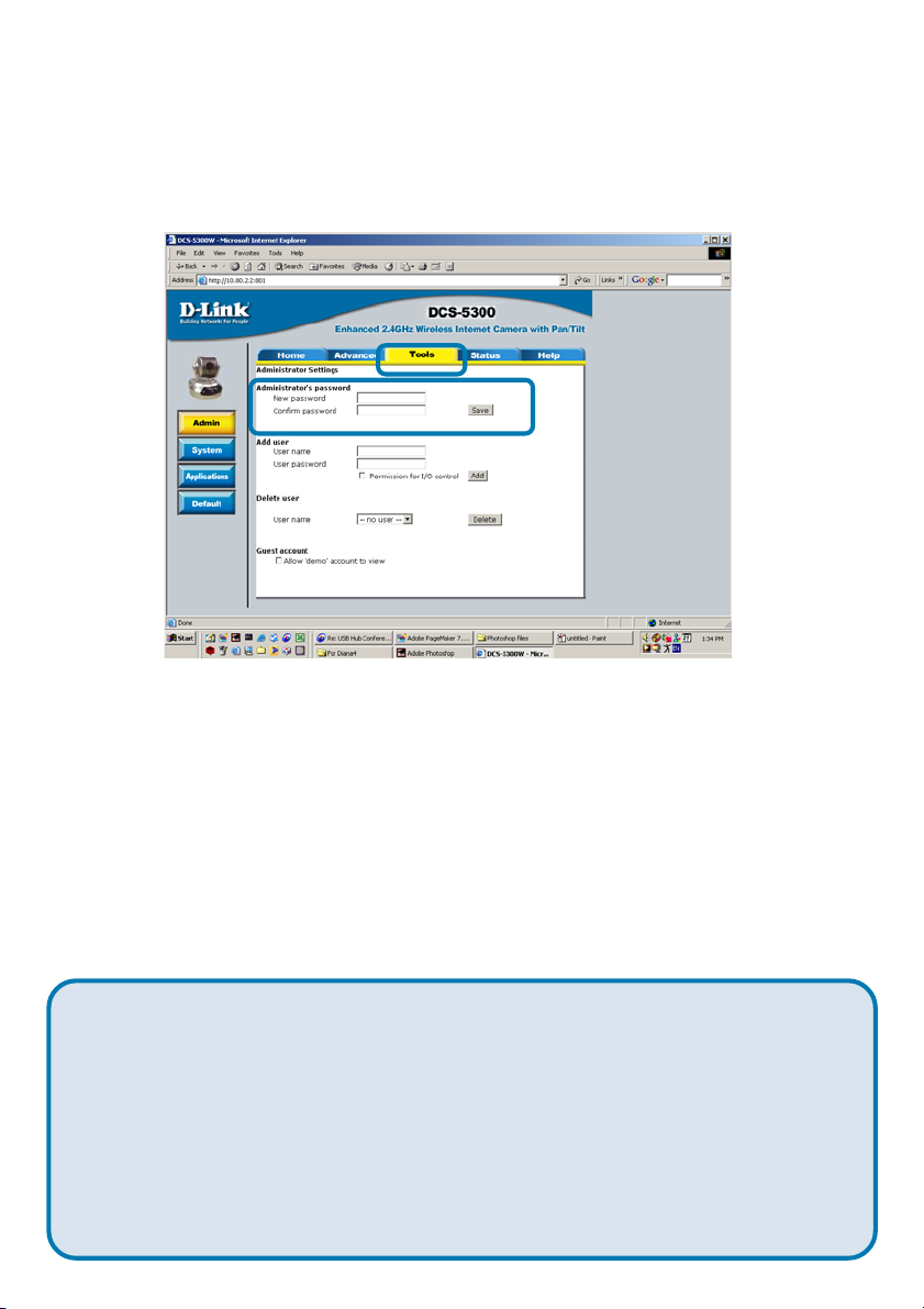
Configuration > Tools > Admin
Click on the Tools tab to access 4 utility screens for controlling and administering
the DCS-5300. The default screen in Tools is the Admin screen.
The DCS-5300 is manufactured without any passwords by default. This
allows the ability to access the DCS-5300 (including the Configuration) by
anyone as long as the IP address is known. It is recommended that you enter
a password if the DCS-5300 is intended to be accessed by others.
Type a password in the New Password field to enable protection, and then
confirm the password in Confirm Password field.
This password is used to identify the administrator. You can add accounts with
User name and User Password for other users in the Add user section.
You can provide up to twenty accounts for other users / visitors. Each account
identifies the access right. This allows multiple visitors to share the same account
of different levels. An option to Permit to access DI/DO (Digital In/Digital Out)
is provided for each account. Some users may need to be prohibited from
controlling your attached security devices.
49
Page 50

Using the DCS-5300 with an Internet browser
(continued)
Configuration > Tools > Admin (continued)
Guest account: This option allows a user to connect to a camera with
view -only privileges. User name is “demo”. No password
is required. This is useful for demonstrations and keeps
guests separate from users with accounts.
Configuration > Tools > System
Click on the System button to access the System settings from the Too l s
menu.
Click System
Host name -
Turn off the LED
indicator -
The text will display as the title at the top of the main
page.
Check this option to shut off the LED next to the lens.
This will prevent anyone from observing the operation
of the Internet Camera.
50
Page 51

Using the DCS-5300 with an Internet browser
(continued)
Configuration > Tools > System
Keep current date and
time -
Sync with computer time-
Manual - Adjust the date and time according to what is
Automatic - Synchronize with the NTP server over the Internet
NTP server - Assign the IP address or domain name of the
Time zone - Used to adjust the hour of timeservers for local
Click to save the current date and time of
DCS-5300. An internal real-time clock maintains
the date and time even when the power is off.
Synchronize the date and time of DCS-5300
with the local computer. The date and time of
the PC is displayed and updated in the
DCS-5300.
entered by the administrator. Notice the format in
the related field while typing.
whenever the DCS-5300 starts up. It will fail if
the assigned timeserver cannot be reached.
timeserver. Leaving the text box blank will let
DCS-5300 connect to default timeservers.
settings.
Click Apply to make
changes effective
51
Page 52

Using the DCS-5300 with an Internet browser
(continued)
Configuration > Tools > Applications
Click on the Applications button to access the Applications settings from the
Tools menu.
52
Page 53

Using the DCS-5300 with an Internet browser
(continued)
Configuration > Tools > Applications (Continued)
Weekly schedule:
Sunday through Saturday - Select the weekdays that should perform the
following operations:
Snapshots begin at -
Snapshots stop at - Sets the time to stop the operations.
Event operation
Delay second(s) before
detecting next event - Sets the time delay before restarting to check the
Take snapshots at second(s)
after event - After a snapshot is taken because of a trigger,
Set the time to start operations. Setting the begin
time the same as the stop time will force the
operations to run continuously.
trigger condition when the current condition is
triggered.
another snapshot will be taken after the configured
time in seconds.
Trigger condition - There are 4 conditions related to the digital input
and three windows for motion detection. There
can be multiple selections. Select the appropriate
digital input condition according to the
characteristics of the external device. “High”, “low”
indicate external voltage input for level trigger,
while “rising”, “falling” is for edge trigger. There
are three windows shown for the name you
defined for motion detection. “Undefined” will
show instead of the window title if motion detection
is not setup yet.
Reset output - Check and save this option to reset the external
device at the digital output back to the original
state.
53
Page 54

Using the DCS-5300 with an Internet browser
(continued)
Configuration > Tools > Applications (Continued)
Trigger action - There are four options for two actions regarding
either trigger condition. They can have multiple
selections. While choosing the trigger output
alarm, the digital output will short both pins to
connect the circuit of the attached external
device; otherwise both pins will be open. While
choosing to upload snapshots, the method can
be either email or FTP. The snapshot names will
be “videopre.jpg”, videotrg.jpg”, and
“videopos.jpg” respectively for the snapshots
before event, right upon event, and after event.
The date and time suffix may be added according
to the option. Confirm the external mail or FTP
server settings in network configuration.
Sequential operation
Snapshot every second(s) -
The DCS-5300 will send snapshots at the
specified interval to the external server according
to the chosen method. Remember this operation
is dependent to the weekly schedule.
Send snapshots by email - Any upload action specified in the options above
will use the method chosen here. The captured
snapshot named “video.jpg” will be attached in
the email with subject “Periodic snapshots.”
Send snapshots by FTP - The captured snapshots will upload to the external
FTP server with the file name depending on the
next option. It can be used to refresh the captured
image stored in the external web server to build
FTP put snapshots with
date and time suffix -
creative homepages.
If the suffix is added, the captured date and time
can be easily differentiated from the snapshot file
name in either sequential or event operation. For
instance, “video@20020102030405.jpg” means
the JPEG image was captured at 4 minutes and 5
seconds after 3 o’clock, January 2nd, A.D. 2002.
If the suffix is omitted, the file named “video.jpg”
on the external FTP server will be refreshed at
the specified interval.
54
Page 55

Using the DCS-5300 with an Internet browser
(continued)
Configuration > Tools > Default
Click Apply to make
changes effective
Click on the Default button to access the factory Default settings from the
Tools menu.
Click Default
Click Apply on the screen to restore the factory default settings. This means
any changes made will be lost and the system will be reset to the initial status
when shipped from the factory. After confirmation, the system will restart and
require the IP Installer software program to setup the DCS-5300.
Configuration > Status > Device Info
Click on the Status tab to access Device Info and a Log of DCS-5300 system
activity. The Device Info is the default screen when you click on the Status
tab.
55
Page 56

Using the DCS-5300 with an Internet browser
(continued)
Click Device Info
The Device Info screen lists the following important settings that are currently
set for the DCS-5300
• Firmware Version number
• Mac Address
• IP Address
• Subnet Mask
• Default router address
• Primary DNS address
• Secondary DNS Address
Configuration > Status > Log
Click on the Log button to access a system log of system activity from the
Status menu. The content of the log file reveals useful information about the
current configuration and connection logged after the DCS-5300 boots up.
Click Log
56
Page 57

Using the DCS-5300 with an Internet browser
(continued)
Configuration > Help
Click on the Help tab to access descriptions of the particular function you need
help with. The help screen is organized in the order of the tabs and then each
menu item under that tab.
57
Page 58

Using IP surveillance Software
Upon completion of the installation of the IP surveillance software, you can run
the Monitor program (for monitoring and recording from the DCS-5300) from
the Windows folder:
Start\ Program Files\D-Link\IP surveillance \Monitor
or the directory you specified during the installation.
There is also a Playback program (for accessing and playing video captured in
the Monitor program.) The Playback program is detailed starting on page 68.
Before using the IP surveillance Software programs you will be asked to set the
admin (administrator) password. The admin password should be at least 6
characters in length.
Click OK
Click OK
A successful message box will show if you set the admin password successfully.
Monitor Program
admin
******
Click OK
An Authentication dialog box will appear. Enter “admin” as the login for the first
time and enter a password. You will see the Monitor program on your display.
58
Page 59

Using IP surveillance Software (continued)
Monitor Program Main Screen
Control up to 16 DCS-5300 Internet cameras from this screen.
Minimum Requirements for Multiple Camera Configurations:
For 1 to 4 channels:
Minimum Requirements
OS: MS Windows2000/XP/ME/98SE
CPU: Intel 500 MHz Pentium III or above
SDRAM: 128 MB SDRAM
Hard Disk: 40GB
For 5 to 9 channels:
Minimum Requirements
OS: MS Windows2000/XP
CPU: Intel 933 MHz Pentium III or above
SDRAM: 128 MB SDRAM
Hard Disk: 40GB
For 10 to 16 channels:
Optimal Requirements
OS: MS Windows2000/XP
CPU: Intel 2.0 GHz MHz Pentium IV or above
SDRAM: 256 MB SDRAM
Hard Disk: 40GB
Display Chip: nVidia, TNT2, GeForce with 32 MB display memory or above
59
Page 60

Using IP surveillance Software (continued)
Monitor Program Main Screen:
Misc. Functions
Channel Area
Image Layout Area
Recording Settings
P/T
Hard Disk Status
Video Area
Features Menu & Alert
Messages
P/T Control
Descriptions of the sections of the Monitor program Main screen:
Miscellaneous functions:
Including quitting the application, snapshot, full screen monitoring,
and Function menu for calling global settings, configuration, and
backup. Tips are provided when you move the mouse cursor on
them.
Channel area
This area displays the status of each video channel (camera)
including: connection, recording, camera selected, and alert
information.
Video area
In this area, you can see the video of the accessed channel, and
some convenient controls.
Layout area
You can change the monitoring layout in this area such as 1
fullscreen image of 1 camera or up to 16 images of different
cameras.
60
Page 61

Using IP surveillance Software (continued)
Recording settings
You can record video onto your hard disk. The recording
schedule is configured in the Scheduler.
Hard disk status
In this area, you can get the hard disk status. This informs you
of the available disk space remaining.
DI/DO control
Receive the digital input signal and send digital output signal.
Alert Message
Display the last alert messages.
Logging In
You need to login to use IP surveillance. There are two privileges in the accountpassword system: the admin (administrator) and the general user.
Click OK
If you have the administrator privilege, you have the right to do the following:
Run the configuration tool
Change the recording schedule
Change the local settings
General users can only monitor the surveillance videos and change the layout
of the Monitor program, but you do not have the right to change any configuration
including recording schedule and local settings.
61
Page 62

Using IP surveillance Software (continued)
When you first login, you should configure the DCS-5300 from the Camera
Configurations menu. Once you set up the administrator privilege, you can
run the Configuration.
A warning message will appear to warn you that any recording that is occuring
will stop when you access Camera Configuration.
Home > Camera Configuration Screen
Function
setting buttons
Camera
Selections
Local Settings
62
Page 63

Using IP surveillance Software (continued)
Home > Camera Configuration Screen (continued)
In the local settings there are four main functions:
Insert – To add cameras to the camera list, specify the IP address and port,
click the Insert button. The program will try to connect to the DCS-5300. If the
connection succeeds, the admin password of the remote DCS-5300 camera
is required. If you provide the correct password, the camera will be inserted in
the list.
Delete – This will delete the selected camera from the camera list.
Password – Changes the local “admin” password.
Stop – Provides a way to stop the network connection when the connection
freezes for a long time.
63
Page 64

Using IP surveillance Software (continued)
Changing the Camera Order in the List
You can drag and drop the gray area (fixed area) of the camera list grid to
change the arrangement of cameras. This makes it easy to rearrange the cameras.
Left-click in the
gray area.
Move the mouse to the location you
want and release the mouse button.
Here video 1 will be moved to the 10th
row.
Motion Window and Alert Settings
Show Window Options – If Motion Detection is enabled for the selected
DCS-5300 camera, each motion window can be turned on in Show Window
Options. Once the motion window is turned on, it will be shown as a green
rectangle in monitoring screen. If you just want to see the motion window when
alerted, you can also turn on the alert window separately. The alert window will
be shown in red rectangle when an alert occurs.
Alert Settings – Some special actions can be performed, such as generating
an alert sound or starting recording when motion is detected or a digital input is
triggered. The digital input can be high-triggered or low-triggered. It depends on
your setting. You can also specify the period to record after the alert-trigger.
64
Page 65

Using IP surveillance Software (continued)
Saving the Changes
Once you click the Save button, the changes in the configuration will be saved
and will validate immediately.
Global Settings
Click on the Global Settings item from
the Function Menu.
This area
indicates backup
status and last
backup time
Snapshot Directory – The directory for storing the snapshot data.
Recording Directory – The directory for storing the recorded video data.
Scheduler Directory – The directory for storing the schedules used for
recording.
65
Page 66

Using IP surveillance Software (continued)
Reserved space – Indicates how many bytes should be reserved on the hard
disk. If the recording data exceeds disk capacity, the new video data will replace
the oldest date (IF the Cycle Recording box is checked). This space can be
adjusted with the sliding bar below it.
Modulation Mode – For selecting the input signal format (NTSC for US use, or
PAL that is used mostly in Europe).
Alert Sound – Select the sound file of your choice in Windows to play when
there is an alert.
Display options – In each video frame, there are two status bars which contain
Camera location, Connect time, Remote time and Record time. All of them
can be individually enabled here.
Location (Channel number + Text on Video)
Connect Time (day hour:min)
1day 04:17
Remote Time
Recording Time (day hour:min)
0 day 00:15
Backup Settings – Select the backup directory, the backup size of your media,
and the backup locations. You can also delete backup locations here. The
maximum locations cannot exceed 32.
Last Backup Time – Indicates the last time a backup occurred. All Backup
means all the data in this location has been backed up, and No Data means
there is no data stored in this location.
Internet Settings – Set the proxy and IP filters.
66
Page 67

Using IP surveillance Software (continued)
Check here to enable proxy.
Set the proxy
Check here to enable filter
Enter IP address to add
Add an IP address
Delete an IP address
Click OK
If you enable proxy server and enable IP restriction, the listed IP
addresses will not use the proxy.
Connecting to the DCS-5300
Once you connect to the DCS-5300, you can drag and drop a camera into the
video area.
In the channel area, if you do not set up the camera, the color of the camera
number will be gray. Once you set up the camera, the color of the camera
number will turn to blue. You can drag and drop the camera into the video
area, and apply other features if you have the privileges by logging on as an
administrator (admin).
There is a unique light signal above each camera’s number. This indicates the
status of the camera:
Off Camera is not connected.
Green The green light means the camera is connected.
Red The red light indicates the camera is both connected and in
Blink If motion detection is enabled, an alert occurs and the light will
–
–
–
recording mode.
–
blink.
67
Page 68

Using IP surveillance Software (continued)
Adding a Channel:
Adding a new camera as a channel can be accomplished with a simple drag and
drop procedure. After you have inserted the camera from the Camera
Configuration screen in the Function Menu, the channel number (shown below)
will change from grayed out to blue (see page 55 to Insert a camera):
1. Click on the number of the camera that was inserted previously:
2. Hold the mouse button down and drag the channel number onto a
droppable video area. The video from the new camera will be displayed
in this video display and the light above the camera number changes
from off to green.
Selected channel to be
viewed in the video area
Recording
Connected & Monitoring
Configured channel
(but not connected)
Not configured channel
Trash Can
Recording button
68
Page 69

Using IP surveillance Software (continued)
Stop Monitoring a Channel
If you don’t want to monitor a video channel, you can drag and drop the video (in
the video area) to the trash can.To delete a channel:
1. Select the video of the channel to be discarded
2. Move the mouse cursor to the channel number.
3. Press and hold the left mouse button, the cursor will change if the
cursor is located in a droppable area.
4. Drag the cursor to the trash can and release the mouse button to
delete the channel.
10:36:13 AM
Channel number
Droppable Areas
Moving Channels to Another Video Area:
The drag and drop can also apply to the change of videos. In the video area, if
you want to exchange the videos of different channels, you can drag the video
and drop it where you want to locate the video. If the destination video box is
empty, then the video in the source video box will be shown on the destination
video box, and the source video box will be empty. If the destination video
box contains video of some channel, then the videos in the source and
destination video box will be exchanged.
69
Page 70

Using IP surveillance Software (continued)
The Layout
There are six layouts in the monitor tool. You can select (by left-clicking on the
icon) which videos you want to monitor. In each layout, you can drag and drop
the “channel number” to any video box in the video area. If all conditions are
okay, then the video will appear in the video box, and the old video is replaced.
6 Camera Layout
1 Camera Layout
9 Cameras Layout
16 Camera Layout
The video positions in each layout are saved for the next time the layout is
selected for monitoring.
When you want to view one individual camera, you can double-click on the
video in the video area. The layout is now changed to the larger, single image
display. You can click the “up” or “down” button to view different cameras, and
clicking the Back to previous layout button will switch to the previous selected
layout.
Back to Previous Layout
Double-click to switch
to larger Size Video
Switch Between Cameras
70
Page 71

Using IP surveillance Software (continued)
Record & Schedule
Record – Record the selected channel manually.
Stop – Stop recording the selected channel
manually.
Scheduling – Arrange recording schedule
Enable Scheduler – Record according to the scheduler
settings.
P/T Control
Refer to the following figure to use the pan and tilt controls.
Return to home position.
Tilt/navigate camer using arrows.
Pan – Pans the camera one full cycle.
Stop – Stops movement of the camera during pan.
Patrol – Enables the Auto Patrol feature.
Pull down menu – Select a preset position to move the camera to.
DI/DO Control
Only one user with the administrator privilege can access the DI/DO control
at the same time. Refer to the following figure to control.
Digital Input is High
Set Digital Output to Low
Set Digital Output to High
71
Page 72

Using IP surveillance Software (continued)
Alert Message
If you turn on the Alert function, and a trigger is set off by motion, an alert
message will show in this window. The message format is described as follows:
“time”=>”alert type” #”channel number”(“win1”,”win2",”win3")
For example, the message “03:47:25 PM=>MO #5(0,1,1)” means that a motion
detection alert occurred at 03:47:25 PM on motion window 2 and motion
window 3.
Backup
The Backup function archives recorded data based on the location and size
you selected in Global Settings. You can duplicate the backup data to a
removable device such as CD-ROM, ZIP disk, DVD-RAM or tape manually. After
the backup starts, you cannot configure the camera or change any settings. You
can cancel the backup process by selecting Cancel Backup option. After the
backup completes, a message appears informing you the backup is complete.
72
Page 73

Using IP surveillance Software (continued)
Miscellaneous Functions
Quit – Close the application and save last settings
Full Screen – Switch to full screen, double click screen to return back
Local Time – Display the current time
Snapshot – Snapshot each view in current layout mode, and save it as bitmap
file to hard disk. You can set the directory in “global settings”.
Stop Alert Sound – Whenever alert occurs, the alert sound will start to play.
You can press this button to stop the alert sound and see the alert messages.
Scheduling
The Scheduling helps you to schedule the recording time of the output from
the DCS-5300. You can easily specify the time of recording via both our
graphic user interface and time period selection. Features include:
To enable scheduling click the Enable Scheduler
box in the Record Settings of the main Monitor
screen.
Easy to use graphical user interface
One-on-one camera scheduling
Up to 9 schedule schemes for each camera
Automatic period recording
73
Page 74

Using IP surveillance Software (continued)
The layout of the scheduler tool is divided into 9 sections. For ease of use,
you may skip to section 7. In section 7, when you input the date, hour and
minute, the times you have selected will appear in the Hour, Day, Week and
Month time-lines (sections 1,2,3 and 4 illustrated here.)
Section 1 of the scheduler tool is the Hour time-line. When you input the
hour in section 7 it will be illustrated in section 1. Alternately, you can enter
the scheduling hour in this timeline although it may be a less efficient method
of inputting the information. You can refer to the Schedule With Time Lines
section in the following pages.
Section 2 is the
Day time-line. When
you schedule the day
in section 7, the result
is displayed here.
Section 3 is the
Week time-line.
Section 4 is the
Month time-line.
1
2
3
4
6
7
Section 5 is the
Current year
selector. Choose the
year here that will be
displayed in Section 7.
Section 6 is the
camera selection and
editing area, it
provides the IP
addresses and location
information for your
reference. Their is an
editing schedule space
for saving a temporary
schedule. This will be
explained in further
detail on the following
pages.
9
5
Sections 7 consists of
Begin time selector, End
time selector, Period
selector, Addition button,
and Erase button. These
components help you
choose a period of time in
which to add or delete
records in the schedule.
Section 9 contains the
operations buttons.
These will be explained
in the following pages.
74
8
Section 8 is the
Time Period
selector. Select
the period of time
at which the
settings will apply.
The Add and
Erase buttons are
also in this section.
A more detailed
explanation of
these features can
be found in the
following pages.
Page 75

Using IP surveillance Software (continued)
Current Year Settings And Camera Selector for the Recording function
By default, the scheduler is running with the
current date selected on the time-lines and
Date-time picker. Therefore, the current
scheduling year is the year that you run the
scheduler tool. To change the year setting:
Use the up (increase) and
down (decrease) arrows to
adjust the year setting.
The Date-time selector in Section 7 (see above) will change the year
concurrently. If you change the year with the Date-time selector, the current
year setting will also be changed.
The following is the Camera selector:
Camera
Here you can make two kinds of schedules: a schedule associated with a specific
camera, or a general schedule that is not applied to a specific camera.
If you want to make a schedule that does not belong to any camera, select the
first row for editing.
If you want to create a schedule for a specific
camera, then click on the row of the camera you
wish to schedule. Select the Open and End
Times. Add any other settings you wish to make.
Click the Add icon to save the changes.
75
Add selected
period schedule
Erase selected
period schedule
Page 76

Using IP surveillance Software (continued)
If users have configured the IP surveillance software and the DCS-5300
camera, the IP address and location will show the correct setting. Please note
that when users switch between cameras, the changing of the schedule will be
saved automatically.
The Schedule-Record-File operations
There are six related buttons. These buttons are illustrated on a prior page, as
section 9 in the Scheduling window:
Load: This operation allows the users to load other schedules
from the schedule database for this camera.
Clear: This operation will clear all the schedule markers in the
current editing area. Note that users must choose
“save” or “refresh” themselves.
Save: The button is for applying the changes for the current
schedule.
Save As: To save the current schedule-record-file to another file
name, this button will perform this.
Undo: Undo the most recent changes.
Close: Click Close to close this window.
76
Page 77

Using IP surveillance Software (continued)
Schedule with Time Picker
Remember to make the Begin Time earlier than the End Time. Otherwise
the Add action will be ignored.
Select period
Once
Every Hour
Every Day
Every Week
After you have made your Begin Time and End Time selections, select a
period. You may want to record only Once, or you may want to record Every
hour, Every day, Every week or Every Month.
Add selected period
schedule
Erase selected
period schedule
When you choose Every Hour, the recording scheduler will be guided only by
the minutes setting. Every hour recording will occur during the minutes that
have been selected. (e.g., if the BeginTime was 2:20pm and the End Time
was 7:40pm then the recording would be in effect from 20 mins past the hour to
40 minutes past the hour for every hour of the day.)
Similarly, if you choose Every day then only the hour and the minute setting will
apply. If you choose Every week then only the day of the week, the hour and
the minute settings are valid. For Every Month, only the date (excluding the
month and year), the hour and the minute are valid settings.
77
Page 78

Using IP surveillance Software (continued)
Playback Program
The Playback program is a powerful tool to assist you in browsing the recorded
video database. It has two display modes (Normal display mode, Preview Mode)
and three playback methods (Full Range, Time Period, Events Preview). The
main tools it provides include:
Powerful play control tool:
• Play
• Stop
• Pause
• Fast play (from x1 to x16)
• Slow play (from /1 to /16)
Convenient display adjustment tool:
• Zoom in (from 1:1 to 2.25:1)
• Zoom out (from 1:1 to 1:2)
• Full screen
Flexible searching range adjustment tool:
• User input (from full range to 1 second)
• Zoom in (from full range to 10 seconds)
• Zoom out (up to full range)
• Page searching
• Full range
Various exporting tools:
• AVI file transducer
• BMP file snapshot
• Output to printer directly
78
Page 79

Using IP surveillance Software (continued)
Playback Program (continued)
Installation of the IP surveillance software is detailed in an earlier section
of this manual titled Installation of IP surveillance Software under the
main section titled Software Installation.
Logging-in
Before you start the Playback software program, it is necessary to login. For
security reasons, only the administrator account can login to Playback. To
change the password of the admin account refer to the section of this manual
titled Logging-In in the main section Using IP surveillance software.
Upon completion of the installation of the IP surveillance software, you can
run the Playback program from:
Start\ Program Files\D-Link\IP surveillance System software\Playback
or the directory you specified during the installation.
Area Selection Indicator
Display Area
Status Area
Histogram Area
The main window will be shown on the top of the screen and the display resolution
will change to 1024x768 automatically. There are four main areas in the window:
Display area, Histogram area, Control area, and Status area. There are
also three controls the Area selection indictor, the Frame selection indictor,
and the Pull bar. Explanations of the main Playback screen follow:
79
Control Area
Pull Bar Area
Page 80

Using IP surveillance Software (continued)
Playback Program (continued)
Display Area
The display area shows the surveillance database of each camera by events
triggered by an alert or by time. You can change the video size through the
Display Adjustment Tool, and the playback method through the Play Control
Tool. Under the normal display mode you can double click on the frame area to
change the frame size to a 1:1 or 2.25:1 ratio. In the Preview mode, double
clicking on any frame area can change the display mode to normal and show a
10-second interval including the event you selected.
Histogram Area
The histogram is an interactive control. Not only can you get the event’s location
in terms of time, but you can select a group of events or period from the event
histogram area and show it on the display area.
Control Area
The control area contains almost all the control selectors and toolboxes you
need to browse the database (except the page control). The Page Control
Tool is located on the right-bottom corner of the display area when the program
is operating in the preview mode. These control tools include location selector,
period selector, playback method selector, jog dial, display adjustment tool,
exporting tool, and system control tool.
Status Area
The Status Area is located at the bottom of the main window. It tells you about
the program status including display mode, display size, display speed, exporting
file format, and exporting file name.
Area Selection Indicator
In the main Playback screen as shown above the display area has been
highlighted with a yellow rectangle. This rectangle is the area selection indicator.
This indicator can be set to either Display Area or Histogram Area, by moving
your mouse cursor to the Area you want to select. When you select the Display
Area, the Display Adjustment Tool will appear in the control area, and if you
select the Histogram Area, the Display Adjustment Tool will disappear and
the Searching Range Adjustment Tool will be shown in the control area.
80
Page 81

Using IP surveillance Software (continued)
Playback Program (continued)
Frame Selection Indicator
The frame selection indicator only appears when you change the display mode
to Preview Mode. It appears as a red rectangle surrounding one of the nine
Event Preview Frames. Once you select one of these frames, you can control
its play status through the jog dial in the control area.
Pull Bar
The Pull Bar is a fast, flexible control for seeking data in the selected time
period. It represents the total length of time in that period. You can click or pull
the indicator on the pull bar to the point you want to see. And the current displaying
video will halt and start to play the video sequence from the point you choose. If
the video sequence has been paused, the display area will show the point you
select without playing. The Pull Bar will only function under the normal display
mode.
Settings
After the main window is shown on the screen, you must modify the settings to
make it work properly. Click on the “Settings” button in the system control
tool, and the dialog box appears on the screen as shown below:
Explanations of the Settings screen are on the following pages.
81
Page 82

Using IP surveillance Software (continued)
Playback Program (continued)
Database path
The most important item in the settings dialog is the database path setting.
You must set it to the directory that contains the surveillance database to
make the program work properly.
AVI file location
It sets the storing directory when you export AVI files. The exported AVI
files will be stored in the sub-directory under the directory you set here
with the name of the location you select.
Bitmap file location
It sets the directory to use the for snapshots when exported as bitmap
files. These exported bitmap files will be stored in the sub-directory under
the directory you set here with the name of the location you select.
AVI Frame rate
This setting changes the color depth of the exporting bitmap file. It is
suggested to use more than 16 bits color depth for the best picture quality.
AVI compression mode
Unlike the exporting of bitmap files, only 16 bits of color depth are used to
export the AVI file. During the AVI compression mode selection, you can
select one of the compression methods that your computer supports to
export the AVI file.
Alert window settings
There are three alert windows you can activate during using the monitor
program. In the playback program, you can choose whether these alert
windows will be shown or not. If you check one window, then you will see
that rectangle in green or red color shown in the displaying video sequence.
Modulation mode
The modulation mode should not be changed without knowledge of the
various modes . The quality of the video depends on how you recorded the
video sequence in the monitor program. If you select the wrong mode, the
video shown in the display area will become deformed. If you choose the
wrong modulation mode, you may open the settings dialog again, change
to the correct mode, and restart the playback program, It should then display
properly.
82
Page 83

Using IP surveillance Software (continued)
Playback Program (continued)
Control panel position
The Control panel provides you a very convenient method to change the position
of the control area to fit your needs.
Once you change the setting of modulation or control panel position, you have
to restart the program to for these changes to take effect. If you set the database
path correctly, the video sequence will start displaying in the normal display
mode when you click on the “OK” button.
Normal (Single Frame) Mode
You can enter the Normal Mode when you:
• Change the database path in the settings dialog
• Change the location selector to another location
• Change the playback method selector to “Full Range”
• Change the playback method selector to “Time Period”
• Double click on one of the nine frames in the display area under
the preview mode.
Under the single frame mode, you can use all the tools the playback program
provided except the Page Control. In this mode, the two labels under the pull
bar show the start and end time of the period individually as shown below:
Period Start Time Label
Histogram Area
The Histogram Area in the single frame mode only shows the event’s occurred
time and the percentage of motion detection with red bars. If you want to access
the Histogram Area, you must change the Area Selection Indicator to the
Histogram Area. You can select a color-inverted region by dragging your mouse
with the left button pressed. When you release the left button, the color-inverted
region will be enlarged to the whole histogram area.
83
Period End Time Label
Page 84

Using IP surveillance Software (continued)
Playback Program (continued)
This color-inverted region will be the new time period the program is going to
display. If you change your mind and don’t want to see that period, you can
cancel it by just pressing the right button of your mouse with the left button still
pressed. If you click on the left button without dragging it, the action will be the
same as clicking on the Pull Bar in the same x-axis position. The dark regions
mean there is no video data in that interval. If you click on those regions, nothing
will happen except a warning message.
Inverted region
Dark Region
Preview (Multiple Frame) Mode
You can enter the preview mode only when you change the playback method
selector to “Events Preview”. Preview Mode helps you to identify the objects
triggering the events via not only the time information and the alert percentage,
but also the video preview playing. This allows you to easily examine different
alert situations. Under the Preview Mode, the Pull Bar, Transducer button in
Exporting Toolbox, and the Display Adjustment Toolbox are all disabled.
The two labels under the pull bar show the displayed event number and the
total event count individually. There are nine frames in the display area and
these are referred to as “one page”. Each frame displays a 10-second interval
video sequence that contains different events. You can use the “Page Up” and
“Page Down” button in the page control to browse the events in the selected
period with nine events per page. And the page status tells you the current page
number and total page count as shown below:
Page Status
Displayed Event Number Total Event Count
84
Page Up
Page Down
Page 85

Using IP surveillance Software (continued)
Playback Program (continued)
Histogram Area
The Histogram Area in the Preview Mode displays events that occurred
previously as red bars, which represent the time and value of the event. Currently
displayed events are represented by green bars and the selected event with
blue bars. If you want to access the histogram area, you must change the Area
Selection Indicator to the Histogram Area. You can select a color-inverted
region by dragging your mouse with the left button pressed.
When you release the left button, the color-inverted region will be enlarged to
the whole Histogram Area. This color-inverted region will be the new period
the program is going to display. If you change your mind and don’t want to see
that period, you can cancel it by just pressing the right button of your mouse
with the left button still pressed. If you click on the left button without dragging
it, the display area will show the event page closest to the point you select. The
dark region means there is no video sequence in that interval. If you click on
these dark regions a warning dialog will appear to inform there is no video
sequence available.
Selector tools
Location selector
Period selector
Playback method selector
Alert area selector
Location Selector
The location selector is a control that lets you select the camera you want to
see. The location information is the same as the location specified in the monitor
program (see Global Settings in the Monitor program section). If there is
more than one database in the same location, another dialog will appear (see
below). You must select an interval in that dialog. The Playback program will
automatically switch to that camera and start displaying.
85
Page 86

Using IP surveillance Software (continued)
Playback Program (continued)
Period Selector
Period selector provides you a precise way to choose the start time and the
end time of a new period. The end time must be later than the start time. After
you give the correct start and end time, clicking on the Play button in the jog dial
will play the new period in the Display Area. If you change the period start and
end time label, the Pull Bar and Histogram Area will change, too. If the selected
period is not present in the database, the data in the period selector will change
to the previous correct start and end time and a warning message will be
displayed.
Playback Method Selector
Full Range
If you select this method, the database will be displayed from the beginning
to the end of this location. Any change in the period selector will take no
effect unless you change this selector to Time Period.
Time Period
If you change the playback method to Time Period, you can modify the
start and end time in the period selector. When you click on the Play button
in the jog dial, the period you select will be displayed.
Events Preview
This method will change the display mode from the Normal display mode
to the Preview mode.
86
Page 87

Using IP surveillance Software (continued)
Playback Program (continued)
Since the program will record the previous start and end time in Time Period
and Events Preview mode. Any time you want to change the period selector
to see another period, you must change the Playback Method Selector to the
mode you want to use first. Otherwise, the Period Selector will back to the
previous data when you change the Playback Method Selector.
Alert Area Selector
In the Preview Mode, the Playback program only can show the total events
information of one alert window each time. If you want to see the events of the
other two alert area windows, you must change the alert area selector to other
numbers. In the normal display mode, the alert window that the alert area selector
indicates will be highlighted with red rectangle if you checked that window in the
settings dialog. The alert area selector will be changed to alert window zero,
when you change the location selector to another one.
Play Control
Speed Indicator
Pause
Play
For the play control, a jog dial is used to provide the easiest way to control the
displaying video sequence. Except the Play button, all other buttons can control
the displaying frame in the normal display mode and the selected displaying
frame in the preview mode.
Forward
Stop
Play
The Play button is an intelligent play interface. The function of this button can
vary to fit with different circumstance. In the normal display mode, click on the
Play button can restart the displaying video sequence. When in the preview
mode, if you don’t change the data of period selector, clicking on this button only
restarts the selected displaying frame. If the data of the period selector has
been changed, clicking on the Play button will restart all frames to display the
first nine events in the new period.
87
Page 88

Using IP surveillance Software (continued)
Playback Program (continued)
Stop
When you want to stop the displaying video sequence, you can click on
the Stop button. Once you have pressed the Stop button, the start point
will be reset to the start of the present period.
Pause
The Pause button provides you a way to pause the displaying video
sequence. When the displaying video is paused, clicking on the Pause
button again will continue the video to display.
Step Forward
This button is only valid when the displaying video sequence is paused. It
will display the next frame in that period when you click on the Step
Forward button one time.
Fast Play and Slow Play
DCS-5300 supports maximum to 16X fast forward play and slow forward play.
This function helps you browse the surveillance database more flexible. If you
want to change the playing speed, you just need to move the speed indicator.
To increase playing speed, move the indicator in the clockwise direction. And to
decrease playing speed, move it in the counterclockwise direction. The current
speed you set will be shown in the second column of status area.
Display Adjustment Toolbox
Using the Display Adjustment Toolbox, you can change the displaying video
sequence to the size you want to see in the normal display mode when you
move the area selection indicator to the display area. Below is the Display
Adjustment Toolbox and its own three elements, i.e. “Zoom In”, “Zoom Out”,
and “Full Screen”.
Zoom In
When you click on the Zoom In button one time, the image size in the display
area will be magnified 12.5 percent to the original size. Due to the limitation of
the display area size, the maximum zoom in ratio supported is 2.25:1 for NTSC
modulation mode and 1.875:1 for PAL modulation mode. If you want to see the
image in more detail, you can use the full screen function in the same toolbox.
88
Page 89

Using IP surveillance Software (continued)
Playback Program (continued)
Zoom Out
When you click on the Zoom Out button one time, the image size in the display
area will be reduced12.5 percent to the original size. To show the location and
time information completely, the minimum zoom out ratio is limited in 0.5:1.
Full Screen
When you click on the Full Screen button, the video sequence will be enlarged
to fill the whole screen. You can double click on any place to return to the
original state. When you switch to full screen display, you can press the “Alt”
and “Space” keys together to pop the jog dial to control the displaying video
sequence. Press the same keys again will close the jog dial. You can also press
the “Alt” and “Enter” keys together to switch between the normal display and
full screen display at any time when the program is under the normal display
mode.
Searching Range Adjustment Toolbox
The Searching Range Adjustment Toolbox provides you a faster way to
change the range of the displayed time period. By using this toolbox, you can
browse the database of one location from any 10-second interval over its entire
range. Below is the Searching Range Adjustment Toolbox with its own three
elements: “Zoom In”, “Zoom Out”, and “Full Range”.
Zoom In
Each time you click on the Zoom In button in the searching range adjustment
toolbox, the displayed time period will be half in the center of the original time
period until the period is equal to 10 seconds. You can see the new interval in
more details. The scale of pull bar and alert histogram window changes and the
period start and end time change, too. The period selector will show the new
start and end time. And the display area will restart to display the new period
from the new start time.
89
Page 90

Using IP surveillance Software (continued)
Playback Program (continued)
Zoom Out
Each time you click on the Zoom Out button in the searching range adjustment
toolbox, the displayed time period will be double in the center of the original time
period unless the start time or end time exceed the database boundary. The
scale of pull bar and alert histogram window changes and the period start and
end time change, too. The period selector will show the new start and end time.
And the display area will restart to display the new period from the new start
time.
Full Range
As you click on the Full Range button, you will get the same functionality as
if you changed the Playback Method Selector to Full Range.
Exporting Toolbox
You can check the database through the Playback program and also export
the database to other media. Using the Exporting Toolbox, you can export the
database to other more portable formats, such as AVI file, bitmap file or paper.
Then you may use Programs such as MicrosoftR Windows Media Player or
other programs to browse the exporting data. Under the normal display mode,
you can use all the exporting tools. And under the preview mode, only snapshot
and print can be used. Shown below are three elements of the Exporting
Toolbox: Transducer, Snapshot, and Print.
Transducer
Using the Transducer tool, you can convert the displayed video sequence to
an AVI format file. Just click on the Transducer button and a dialog box appears
(shown below) asking to confirm transforming a database into an AVI file. When
you click on the “OK” button, the conversion procedure will be started.
90
Page 91

Using IP surveillance Software (continued)
Playback Program (continued)
The time required to Export data depends on the speed of the computer and
processor that you are using. At any time during the export, you can click on
the Stop button in the jog dial to stop the procedure. Then you will get an AVI file
from the start time to the time you clicked the Stop button. The exported AVI
filename will be generated automatically and will be listed in the fourth column of
the status area. If you want to change the output directory, you can go to the
Settings Window (See Page 71). To increase the quality of an exported AVI
file, it is suggested to set the video format to normal size, please refer to the
Camera Configuration section (see Page 52).
When you click on the Snapshot button one time, the program will export a
bitmap. In the normal display mode, the exporting bitmap is the image shown in
the display area. And in the Preview Mode, it is the image that you selected
through the Frame Selection Indicator. The size of the bitmap will be the
same as that of the image you select. The exported bitmap filename will be
generated automatically and listed in the fourth column of the status area. If you
want to change the output directory, you can go to the Settings window.
When you click on the Print button, a dialog box will appear. After you make
your selection and send to the printer, the images on the Display Area will be
printed out.
Snapshot
Print
91
Page 92

Using IP surveillance Software (continued)
Playback Program (continued)
System Control Toolbox
The System Control Toolbox provides basic operations for the playback program.
The three elements of the system control toolbox:. “Lock Window”, “Settings”,
and “Exit”.
Lock Window
To protect your computer while left unattended you can click on the Lock
Window button to lock the main window. Once you click this button, the main
window will be hidden and the login dialog will appear. To return to the main
window, you need to enter the admin password again.
Settings
The settings dialog will pop up when you click the Settings button. For more
information regarding these settings see Pages 71and 72.
Quit
The playback program will terminate when you click on the Quit button. If the
AVI exporting procedure is running, this procedure will be stopped first.
92
Page 93

Firmware Upgrades
The DCS-5300 Internet Camera supports firmware upgrades (the software
that controls the operation in the DCS-5300). D-Link will supply the latest
firmware version on the D-Link support Web site at: support.dlink.com.
To upgrade the firmware:
Download the latest firmware file from D-Link.
Click on the file Upgrade Wizard located on the CD enclosed with the
DCS-5300.
Power on the DCS-5300 and connect it to the Ethernet port of your computer.
The Wizard will ask for the IP Address of your camera and for your administrator
password:
Click Next
The Upgrade Wizard will attempt to find the DCS-5300. If it cannot, an error
message indicating this will appear.
93
Page 94

Firmware Upgrades (continued)
If the Upgrade Wizard finds the Internet Camera the following screen asks for
the file name or gives you the choice to browse for the file. The file name should
be FLASH.BIN for the DCS-5300 Internet Camera.
Click Next
The firmware file is scanned by the Upgrade Wizard and the version is reported
to you.
Click Yes
94
Page 95

Firmware Upgrades (continued)
After clicking “Yes” the upgrade begins. The progress of the upgrade is displayed
on the this screen:
Click Exit
Warning
The download firmware procedure cannot be interrupted.
If the power or network connections are broken during
the download procedure it might possibly cause serious
damage to the Internet Camera.
95
Page 96

Appendix
Frequently Asked Questions
Internet Camera Features
Q: What is an Internet Camera?
A: The Internet Camera is a stand-alone system connecting directly to an Ethernet
or Fast Ethernet network. It differs from a conventional PC Camera, the Internet
Camera is an all-in-one system with built-in CPU and web-based solutions
providing a low cost solution that can transmit high quality video images for
monitoring. The Internet Camera can be managed remotely, accessed and
controlled from any PC/Notebook over an Intranet or the Internet from a web
browser.
Q: What is the maximum number of users that can be allowed to access
DCS-5300 simultaneously?
A: The maximum number of users that can log onto the Internet Camera at the
same time is 10. Please keep in mind the overall performance of the transmission
speed will slow down when many users are logged on.
Q: What algorithm is used to compress the digital image?
A: The Internet Camera utilizes H.263+ MPEG-4 Short Header Mode image
compression technology providing high quality images. MPEG is a standard for
image compression and can be applied to various web browser and application
software without the need to install extra software.
Q: Can I capture still images from the Internet Camera?
A: Yes you are able to capture still images with the snapshot function from the
software application CD supplied with the Internet Camera.
Internet Camera Installation
Q: Can the Internet Camera be used outdoors?
A: The Internet Camera is not weatherproof. It needs to be equipped with a
weatherproof case to be used outdoors and it is not recommended.
Q: What network cabling is required for the Internet Camera?
A: The Internet Camera uses Category 5 UTP cable allowing 10 Base-T and
100 Base-T networking.
96
Page 97

Frequently Asked Questions (continued)
Q: Can the Internet Camera be setup as a PC-cam on a computer?
A: No, the Internet Camera is used only on an Ethernet or Fast Ethernet network.
The D-Link DSB-C110, DSB-C310, can be used as a PC Camera (Webcam).
Q: Can the Internet Camera be connected on the network if it consists of
only private IP addresses?
A: The Internet Camera can be connected to a LAN with private IP addresses.
Q: Can the Internet Camera be installed and work if a firewall exists on
the network?
A: If a firewall exists on the network, port 80 is open for ordinary data
communication. The DCS-5300 uses port 5001for control and synchronization,
port 5002 for streaming audio and port 5003 for streaming video. These ports
(or the ports you specify from the Advanced Tab in the Configuration screen if
you change the default ports) need to be opened on the firewall.
Q: Why am I unable to access the Internet Camera from a web browser?
A1: The possible cause might be the IP Address for the Internet Camera is
already being used by another device. To correct the possible problem, you
need to first disconnect the Internet Camera from the network. Then run the
PING utility (follow the instructions in the Appendix - How to Ping Your IP
Address.)
In Windows 95/98/2000 and Windows NT, check that the IP Address of the
Internet Camera is within the same subnet as your workstation.
Click Start, Setting, Control Panel, and the Network icon.
Select TCP/IP from the Network dialog box and from the TCP/IP Properties
dialog box click on Specify an IP address.
If the Internet Camera is situated on a different subnet than your workstation,
you will not be able to set the IP address from this workstation. To verify
make sure the first 3 sections of the IP address of the Internet Camera
corresponds to the first 3 sections of the workstation. Therefore the IP
address of the Internet Camera must be set from a workstation on the
same subnet.
A2: Other possible problems might be due to the network cable. Try replacing
your network cable. Test the network interface of the product by connecting a
local computer to the unit, utilizing a standard Crossover Cable. If the problem is
not solved the Internet Camera might be faulty.
97
Page 98

Frequently Asked Questions (continued)
Q: I connected the Internet Camera directly to a computer with a crossover cable Ethernet cable and received the following Windows error upon
running IP Installer:
A1: This Windows error will occur if the Internet Camera is connected to a
computer that is not properly configured with a valid IP address. Turn off DHCP
from the Network Settings in Windows and configure the computer with a valid
IP address or connect the camera to a router with DHCP enabled.
A2:This error can also occur if the IP Installer icon is clicked on more than
once from the setup wizard.
Q: Why does the Internet Camera work locally but not externally?
A1: Might be caused from the firewall protection. Check the Internet firewall
with your system administrator. The firewall may need to have some settings
changed in order for the Internet Camera to be accessible outside your local
LAN.
A2: Make sure that the Internet Camera isn’t conflicting with any web server
you may have running on your network.
A3: The default router setting might be a possible reason. Check that the
configuration of the router settings allow the Internet Camera to be accessed
outside your local LAN.
Q: Why does a series of broad vertical white lines appear throughout
the image?
A: It could be that the CMOS sensor has become overloaded when it has been
exposed to bright lights such as direct exposure to sunlight or halogen lights.
Reposition the Internet Camera into a more shaded area immediately as prolonged
exposure to bright lights will damage the CMOS sensor.
Q: The focus on the Internet Camera is bad, how can I correct it?
A1: Adjust the Internet Camera focus manually as described in “Adjusting the
Internet Camera Focus” in the Appendix section of this manual.
A2: If you have previously changed the supplied CS-type lens, you may have
unintentionally installed a C-type lens without fitting the adaptor first.
98
Page 99

Frequently Asked Questions (continued)
Q: Noisy images occur. How can I solve the problem?
A1: The video images might be noisy if the DCS-5300 is used in a very low light
environment. To solve this issue you need more lighting.
Q: The images are of poor quality, how can I improve the image quality?
A1: Make sure that your computer’s display properties are set to at least 15-bit
color. Using 16 or 256 colors on your computer will produce dithering artifacts in
the image, making the image appear to be of poor quality.
A2: The configuration on the Internet Camera image display is incorrect. Through
the Advanced>Configuration section of the Web management you need to
adjust the image related parameters such as brightness, contrast, hue and
power line frequency for fluorescent light . Please refer to the
Advanced>Configuration>Video section on Page 35 and 36 for detailed
information.
How to PING Your IP Address
The PING (Packet Internet Groper) command can determine whether a specific
IP address is accessible by sending a packet to the specific address and waiting
for a reply. It can also provide a very useful tool to confirm if the IP address
conflicts with Internet Camera over the network.
Follow the step-by-step procedure below to utilize the PING command but first
you must disconnect Internet Camera from the network.
Start a DOS window.
Type ping x.x.x.x, where x.x.x.x is the IP address of the Internet Camera.
The replies, as illustrated below, will provide an explanation to the problem.
99
Page 100

Reset and Restore
There is a button hidden in the pinhole beside the Ethernet socket. It is
used to reset the system or restore the factory default settings. Sometimes
resetting the DCS-5300 will return the system back to a normal state. If the
system still has problems after reset, restore the factory settings and install
again:
RESET: 1.
3.
RESTORE:1.
Lightly insert a paper clip (or a similar sized tool) into the
reset hole on the back of the camera, press lightly and
then release the button.
2. The LED on the front of the camera will begin blinking
red and green.
When the LED stops the blinking the reset has
completed.
Insert the paperclip or other tool and press on the
button continuously.
Wait for the LED on the front of the camera to blink red
2.
and green and hold the button through two cycles of
blinking (about 5-7 seconds.)
3.
Withdraw the tool after the second cycle of the LED
blinking and a factory restore has been completed.
Reset button
Restoring the factory defaults will result in the
loss of any previous settings and will require
running the IP Installer to return the DCS-5300
to a normal state.
100
 Loading...