

8500 Tracking System
Operator’s
Manual
CMW
®
Issue 1.0 053-1254

8500 Tracking System Manual Overview - 1
Overview
Chapter Contents
Serial Number Location . . . . . . . . . . . . . . . . . . . . . . 2
Intended Use . . . . . . . . . . . . . . . . . . . . . . . . . . . . . . 3
About This Manual . . . . . . . . . . . . . . . . . . . . . . . . . . 3
• Bulleted Lists . . . . . . . . . . . . . . . . . . . . . . . . . . . . . . . . . . . . . . . . . . . . . .3
• Numbered Lists . . . . . . . . . . . . . . . . . . . . . . . . . . . . . . . . . . . . . . . . . . . .3
• “Continued” Indicators . . . . . . . . . . . . . . . . . . . . . . . . . . . . . . . . . . . . . . .3
FCC Statement - Internal Transmitter . . . . . . . . . . . 4
CMW
Overview - 2 8500 Tracking System Operator’s Manual
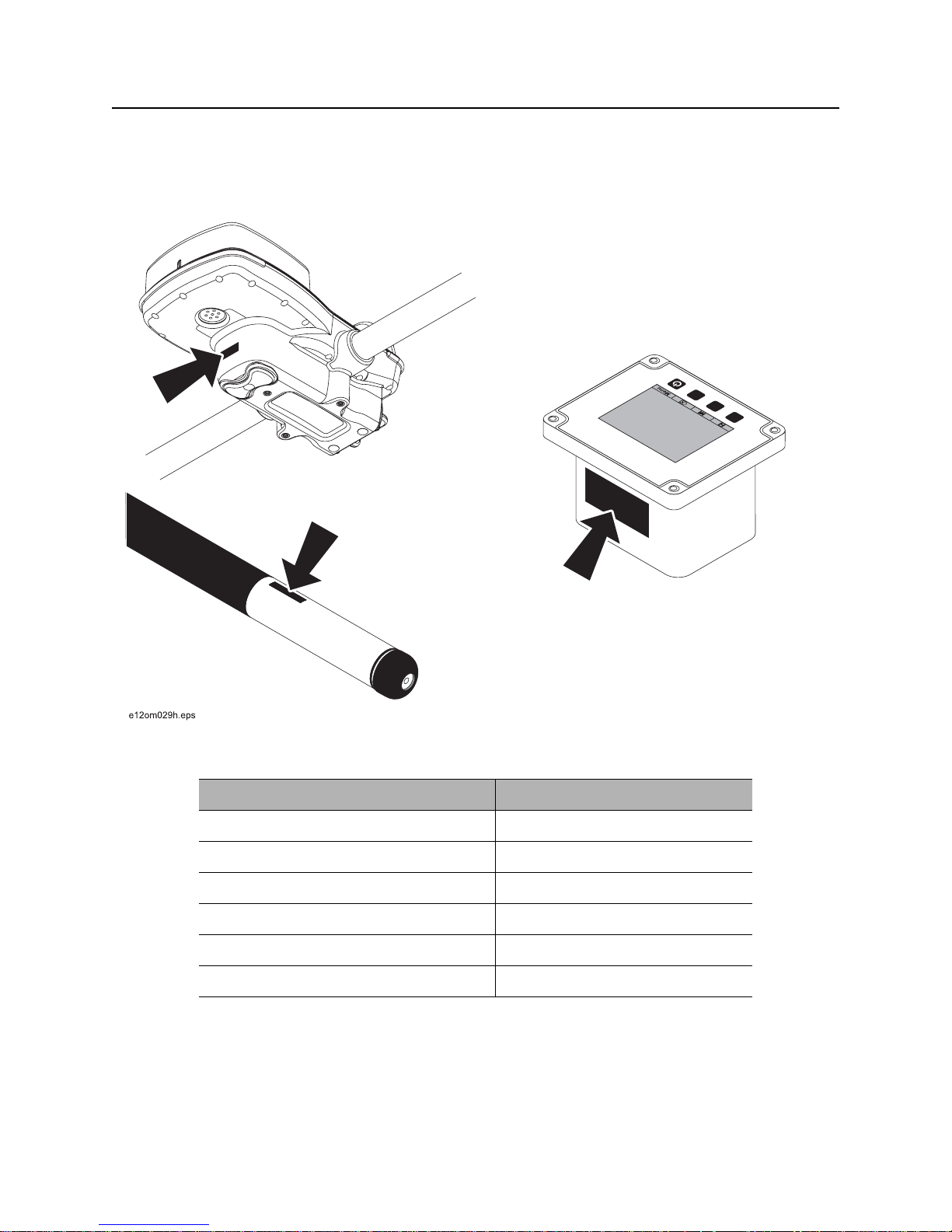
Serial Number Location
Serial Number Location
Record serial numbers and date of purchase in spaces provided. Serial numbers are located as shown
and displayed briefly in lower left corner of tracker and display screens when unit s are first powered up.
Item
date of purchase:
tracker serial number:
display serial number:
accessory model and serial number:
accessory model and serial number:
accessory model and serial number:
CMW

8500 Tracking System Manual Overview - 3
Intended Use
Intended Use
The 8500 tracking system consists of an 8500TK tracker, an 8500D remote display, and an 850 series
beacon. The system provides advanced locating features to 30’ (9 m) dee p. It also p rovides of fset locating
and depth capability. The system provides projected direction information and offers a Drill-Thru guidance
mode. The system can track grade drilling bores with the addition of an 850 series grade beacon and other
grade drilling accessories.
The system is designed for operation in temperatures typically experienced in earth moving and
construction work environments. Use in any other way is considered contrary to the intended use. The
8500 tracking system should be operated only by persons familiar with its particular characteristics and
acquainted with the relevant safety procedures. The system should be serviced only by Ditch Witch
Electronics repair centers.
About This Manual
This manual contains information for the proper use of this equipment. Cross references such as “See
page 50” will direct you to det ailed procedures.
Bulleted Lists
Bulleted lists provide helpful or important information or contain procedure s that do not have to be
performed in a specific order.
Numbered Lists
Numbered lists contain illustration callouts or list steps that must be performed in order.
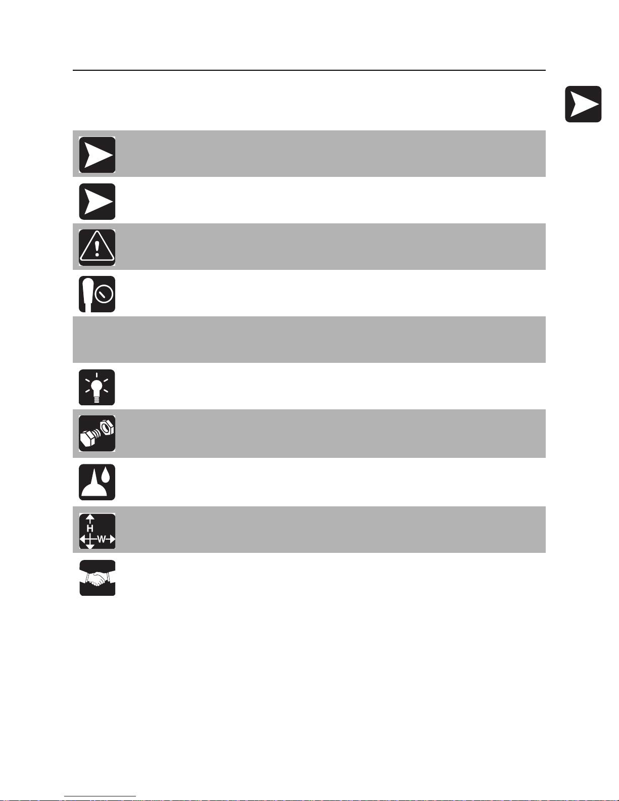
“Continued” Indicators
indicates that a procedure is continued on the next page.
CMW

Overview - 4 8500 Tracking System Operator’s Manual
FCC Statement - Internal Transmitter
FCC Statement - Internal Transmitter
Contains FCC ID: TFB-FREESTAR
This device complies with Part 15 of the FCC Rules. Operation is subject to the following two conditions:
(1) this device may not cause harmful interference, and (2) this device must accept any interference
received, including interference that may cause undesired operation.
Changes or modifications not expressly approved by The Charles Machine Works, Inc. could void the
user’s authority to operate the equipment.
Contains IC: 5969A-FREESTAR
N 16819
CMW

8500 Tracking System Manual Foreword - 5
Foreword
This manual is an important part of your equipment. It provides safety information and operation
instructions to help you use and maintain your Ditch Witch equipment.
Read this manual before using your equipment. Keep it with the equipmen t at all times for future reference.
If you sell your equipment, be sure to give this manual to the new owner.
If you need a replacement copy, contact your Ditch Witch dealer. If you need assistance in locating a
dealer, visit our website at www.ditchwitch.com or write to the following address:
The Charles Machine Works, Inc.
Attn: Marketing Department
PO Box 66
Perry, OK 73077-0066
USA
The descriptions and specifications in this manual are subject to change without notice. The Charles
Machine Works, Inc. reserves the right to improve equipment. Some product improvements may have
taken place after this manual was publishe d. For the latest information on Ditch Witch equipment, see your
Ditch Witch dealer.
Thank you for buying and using Ditch Witch equipment.
CMW

Foreword - 6 8500 Tracking System Operator’s Manual
8500 Tracking System
Operator’s Manual
Issue number 1.0/OM-4/08
Part number 053-1254
Copyright 2008
by The Charles Machine Works, Inc.
, Ditch Witch, CMW, AutoCrowd, Jet Trac, Roto Witch, Subsite, Fluid Miser,
Power Pipe, Super Witch, Pierce Airrow, The Underground, The Underground Authority Worldwide, and
Zahn are registered trademarks of The Ch ar les Mac hin e Works, Inc.
CMW
8500 Tracking System Operator’s Manual Contents - 7
Content s
Overview
machine serial number, information about the type of work this machine is designed
to perform, basic machine components, and how to use this manual
Foreword
part number, revision level, and publication date of this manual, and factory contact
information
Safety
machine safety alerts and emergency procedures
Controls
machine controls and how to use them
System Operation
procedures for tracking beacon signals
Tracking Concepts
basic information for tracking beacon signals
Systems and Equipment
status messages, beacon information, TMS Plus interface instructions
1
5
9
13
33
47
51
Service
service intervals and instructions for this machine
Specifications
machine specifications including weights and measurements
Support
the warranty policy for this machine, and procedures for obtaining warranty
consideration and training
59
63
67
CMW

Contents - 8 8500 Tracking System Operator’s Manual
CMW

8500 Tracking System Operator’s Manual Safety - 9
Safety
Chapter Contents
Guidelines . . . . . . . . . . . . . . . . . . . . . . . . . . . . . . . . 10
Safety Alert Classifications . . . . . . . . . . . . . . . . . . 11
Safety Alerts . . . . . . . . . . . . . . . . . . . . . . . . . . . . . . 12
CMW

Safety - 10 8500 Tracking System Operator’s Manual
Guidelines
Guidelines
Follow these guidelines before operating any jobsite equipment:
• Complete proper training and read operator’s manual before using equipment.
• Contact One-Call (888-258-0808) and any utility companies which do not subscribe to One-Call. Have
all underground pipes and cables located and marked before operating equipment. If you damage a
utility, contact utility company.
• Classify jobsite based on its hazards and use cor rect tools and machin ery, safety e quipment, and work
methods for jobsite.
• Mark jobsite clearly and keep spectators away.
• Wear personal protective equipment.
• Review jobsite hazards, safety and emergency procedures, and individual responsibilities with all
personnel before work begins.
• Replace missing or damaged safety signs.
• Use equipment carefully. Stop operation and investigate anything that does not look or feel right.
• Contact your equipment dealer if you have any question about operation, maintenance, or equipment
use.
CMW

8500 Tracking System Operator’s Manual Safety - 11
Safety Alert Classifications
Safety Alert Classifications
These classifications and the icons defined on the following pages work together to alert you to situations
which could be harmful to you, jobsite bystanders or your equipment. When you see these words and
icons in the book or on the unit, carefully read and follow all instructions. YOUR SAFETY IS AT STAKE.
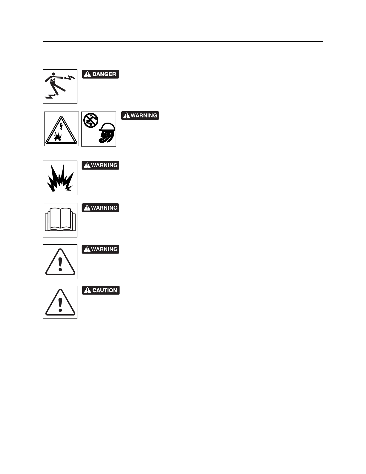
Watch for the three safety alert levels: DANGER, WARNING and CAUTION. Learn what each level
means.
indicates an imminently hazardous situation which, if not avoided, will result in death or
serious injury.
indicates a potentially hazardous situation which, if not avoided, could result in death or
serious injury.
indicates a potentially hazardous situation which, if not avoided, may result in minor or
moderate injury.
Watch for two other words: NOTICE and IMPORTANT.
NOTICE can keep you from doing something that might damage the unit or someone's property. It can also
alert you against unsafe practices.
IMPORTANT can help you do a better job or make your job easier in some way.
CMW
Safety - 12 8500 Tracking System Operator’s Manual
Safety Alerts
Safety Alerts
Electric shock. Contacting electric lines will cause death or serious injury.
Know location of lines and stay away.
Jobsite hazards could cause death or serious injury. Use
correct equipment and work methods. Use and maintain proper safety
equipment.
Explosion possible. Serious injury or equipment damage could occur.
Follow directions carefully .
Incorrect procedures could result in death, injury, or property damage.
Learn to use equipment correctly.
Moving traffic - hazardous situation. Death or serious injury could result.
Avoid moving vehicles, wear high visibility clothing, post appropriate warning signs.
Potential radio frequency (RF) hazard. Operating this device within 4” (100
mm) of your body may cause RF exposure levels to exceed FCC RF exposure limits and
should be avoided.
CMW

8500 Tracking System Operator’s Manual Controls - 13
Controls
Chapter Contents
8500TK . . . . . . . . . . . . . . . . . . . . . . . . . . . . . . . . . . 14
• Icons . . . . . . . . . . . . . . . . . . . . . . . . . . . . . . . . . . . . . . . . . . . . . . . . . . . .14
• Buttons . . . . . . . . . . . . . . . . . . . . . . . . . . . . . . . . . . . . . . . . . . . . . . . . . .17
• Menu . . . . . . . . . . . . . . . . . . . . . . . . . . . . . . . . . . . . . . . . . . . . . . . . . . .19
8500D . . . . . . . . . . . . . . . . . . . . . . . . . . . . . . . . . . . 23
• Icons . . . . . . . . . . . . . . . . . . . . . . . . . . . . . . . . . . . . . . . . . . . . . . . . . . . .23
• Buttons . . . . . . . . . . . . . . . . . . . . . . . . . . . . . . . . . . . . . . . . . . . . . . . . . .25
• Menu . . . . . . . . . . . . . . . . . . . . . . . . . . . . . . . . . . . . . . . . . . . . . . . . . . .28
CMW
Controls - 14 8500 Tracking System Operator’s Manual
8500TK
8500TK
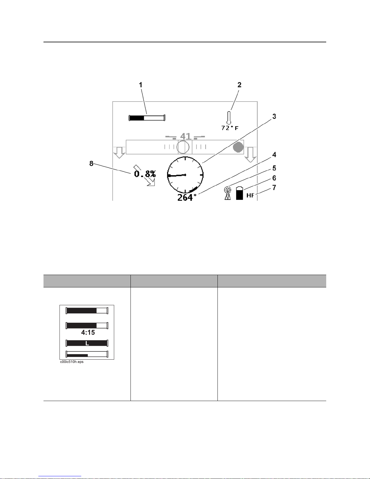
Icons
1. Beacon battery life indicator
2. Beacon temperature
3. Beacon roll indicator
4. Beacon roll value
Item Description Notes
1. Beacon battery life
indicator
Graphically indicates battery
life remaining.
If beacon is within 5 minutes
of entering sleep mode, a
countdown timer will appear
below icon.
An “L” appears in the icon if a
Lithium battery is installed.
In 2-axis view (bottom icon),
replace battery if either axis
disappears.
5. Communication indicator
6. Tracker battery life indicator
7. Frequency indicator
8. Beacon pitch
Battery power (horizontal axis) and
beacon throttle (vertical axis) are
monitored in this view. See “Beacon
Throttle” on page 56.
CMW

8500 Tracking System Operator’s Manual Controls - 15
8500TK
Item Description Notes
2. Beacon temperature Displays beacon temperature
and flashes if temperature
becomes too high.
Icon darkens as temperature
rises and temperature is
displayed numerically below
the icon.
3. Beacon roll indicator Graphically indicates
beacon’s roll position.
4. Beacon roll value Numerically displays
beacon’s roll position in
degrees, minutes or hours.
5. Communication
indicator
Indicates tracker and display
are communicating properly.
IMPORTANT: An audible warning is
activated when beacon temperature is
155°F (68°C).
6. Tracker battery Indicates amount of battery
7. Frequency indicator Displays “HF” when high
power remaining for the
tracker.
Flashes when batteries need
to be replaced.
frequency beacon is selected.
Displays “LF” when low
frequency beacon is selected.
CMW

Controls - 16 8500 Tracking System Operator’s Manual
8500TK
Item Description Notes
8. Beacon pitch Displays pitch of beacon in
percent grade or degrees.
The arrow behind the value
indicates whether pitch is
positive or negative.
CMW
8500 Tracking System Operator’s Manual Controls - 17
8500TK
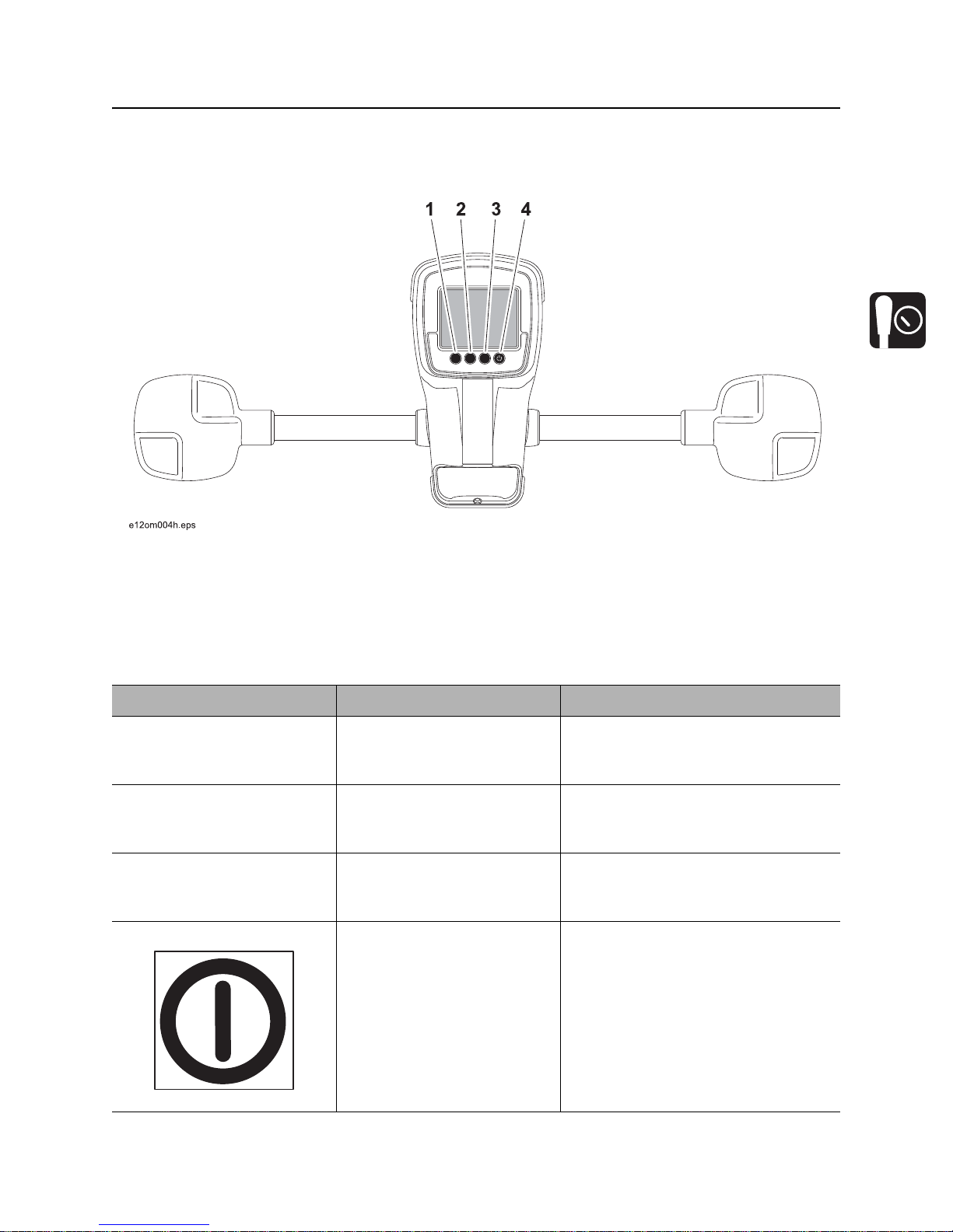
Buttons
Overview
1. Soft button
2. Soft button
Item Description Notes
1. Soft button Function depends on
selected mode and is
indicated above button.
2. Soft button Function depends on
selected mode and is
indicated above button.
3. Soft button Function depends on
selected mode and is
indicated above button.
4. Power button To turn on, press once.
To turn off, press for 2
seconds.
3. Soft button
4. Power button
Button is also used to access quick
functions.
Button is also used for quick
functions.
Button is also used for quick
functions.
Button is also used for quick
functions.
si1017a-d.eps
CMW

Controls - 18 8500 Tracking System Operator’s Manual
8500TK
Quick Functions
Contrast Adjustment
To adjust contrast, pr ess and hold lef t button (1) and pr ess button 2 to da rken/increase contrast or butto n 3
to lighten/lessen contrast.
Backlight Toggle
To turn backlight on and of f, press and hold left button (1) and press power (4) button. Don’t press power
button for more than 2 seconds to avoid turning unit off.
CMW
8500 Tracking System Operator’s Manual Controls - 19
8500TK
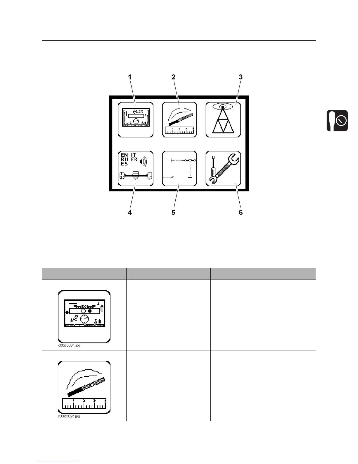
Menu
Overview
1. Display settings
2. Beacon settings
3. Radio options
Item Description Notes
1. Display settings Highlight icon and press
select to enter the “display
settings” menu.
2. Beacon settings Highlight icon and press
select to enter the “beacon
settings” menu.
4. System settings
5. Drill-Thru mode
6. Service menu
See “Display Settings” on page 21.
See “Beacon Settings” on page 21.
CMW
Controls - 20 8500 Tracking System Operator’s Manual
8500TK
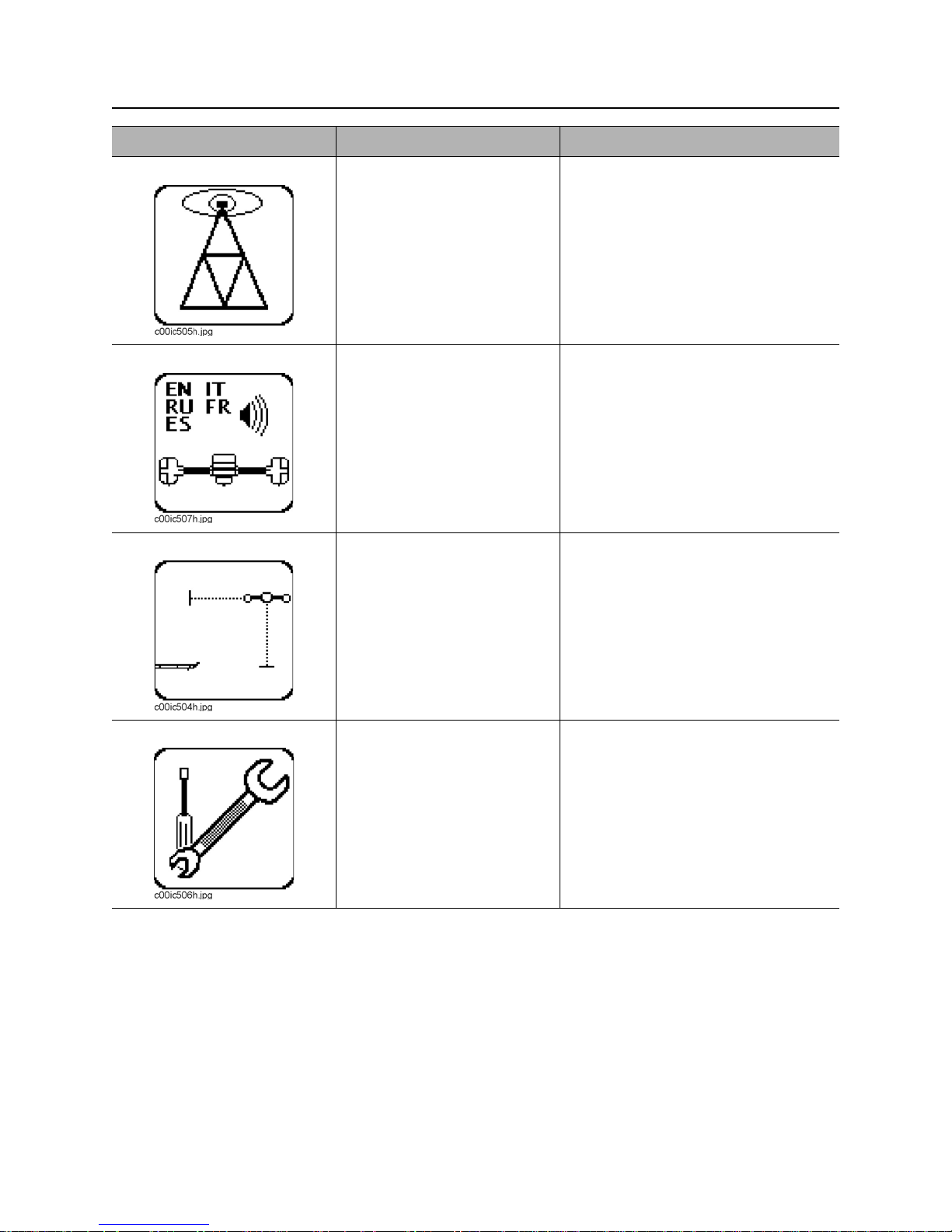
Item Description Notes
3. Radio options Highlight icon and press
select to enter the “radio
options” mode.
4. System settings Highlight icon and press
select to enter the “system
settings” menu.
5. Drill-Thru mode Highlight icon and press
select to enter the drill-thru
mode.
See “Radio Options” on page 22.
See “System Settings” on page 22.
See “Drill-Thru Mode” on page 43.
6. Service menu Highlight icon and press
select to enter “service
menu.”
CMW
See “Service Menu” on page 22.

8500 Tracking System Operator’s Manual Controls - 21
8500TK
Descriptions
Display Settings
Description Notes
LCD Backlight Controls backlight intensity.
Available settings: 0 (off) to 100 (brightest, default).
LCD contrast Controls contrast of LCD.
Available settings: -20 (lighter) to 20 (darker), 0 is default.
Units Controls displayed units of depth values, tempera tures and other
numbers.
Available distance settings: inches, ft in (default), decimal ft, meters,
centimeters.
Depth disp. time Controls how long depth information is locked on the screen after
pressing depth button.
Available settings: 0-60 seconds, 5 is default.
Roll angle disp. Controls display of numerical value of the roll indicator.
Available settings: off (default), degr ees, minutes, hours.
Pitch disp. Controls display of beacon pitch indicator.
Available settings: percent (default), degrees.
Battery ind. style Controls display of beacon battery indicator.
Available settings: 1-axis (default), 2-axis.
Beacon Settings
Description Notes
Beacon freq. Sets tracker receiving frequency.
Available settings: high (default), low.
Beacon calibration Calibrates tracker to beacon.
Roll calibration Sets roll position for beacon equivalent to bit pointing up (12 o’clock, 0
minutes, 0°).
Pitch calibration Sets 0.0% pitch position for grade beacon (1.0% limit).
Depth adjustment Changes built-in adjustment of depth measurements.
CMW
 Loading...