

Page 1
8500 Tracking System
Operator’s
Manual
CMW
®
Issue 2.0 053-1254
ORIGINAL INSTRUCTION
Page 2

8500 Tracking System Manual Overview - 1
Overview
Chapter Contents
Serial Number Location . . . . . . . . . . . . . . . . . . . . . . 2
Intended Use . . . . . . . . . . . . . . . . . . . . . . . . . . . . . . 3
About This Manual . . . . . . . . . . . . . . . . . . . . . . . . . . 3
• Bulleted Lists . . . . . . . . . . . . . . . . . . . . . . . . . . . . . . . . . . . . . . . . . . . . . 3
• Numbered Lists . . . . . . . . . . . . . . . . . . . . . . . . . . . . . . . . . . . . . . . . . . . 3
• “Continued” Indicators . . . . . . . . . . . . . . . . . . . . . . . . . . . . . . . . . . . . . . 3
FCC Statement - Internal Transmitter . . . . . . . . . . 4
RF Exposure Statement . . . . . . . . . . . . . . . . . . . . . 4
CMW
Page 3
Overview - 2 8500 Tracking System Operator’s Manual
Serial Number Location
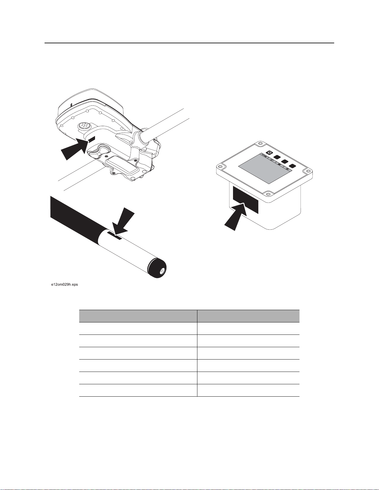
Serial Number Location
Record serial numbers and date of purchase in spaces provided. Serial numbers are located as shown
and displayed briefly in lower left corner of tracker and display screens when units are first powered up.
CMW
Item
date of purchase:
tracker serial number:
display serial number:
accessory model and serial number:
accessory model and serial number:
accessory model and serial number:
Page 4

8500 Tracking System Manual Overview - 3
Intended Use
Intended Use
The 8500 tracking system consists of an 8500TK tracker, an 8500D remote display, and an 850 series
beacon. The system provides advanced locating features to 30’ (9 m) deep. It also provides offset locating
and depth capability. The system provides projected direction information and offers a Drill-Thru guidance
mode. The system can track grade drilling bores with the addition of an 850 series grade beacon and other
grade drilling accessories.
The system is designed for operation in temperatures typically experienced in earth moving and
construction work environments. Use in any other way is considered contrary to the intended use. The
8500 tracking system should be operated only by persons familiar with its particular characteristics and
acquainted with the relevant safety procedures. The system should be serviced only by Ditch Witch
Electronics repair centers.
About This Manual
This manual contains information for the proper use of this equipment. Cross references such as “See
page 50” will direct you to detailed procedures.
Bulleted Lists
Bulleted lists provide helpful or important information or contain procedures that do not have to be
performed in a specific order.
Numbered Lists
Numbered lists contain illustration callouts or list steps that must be performed in order.
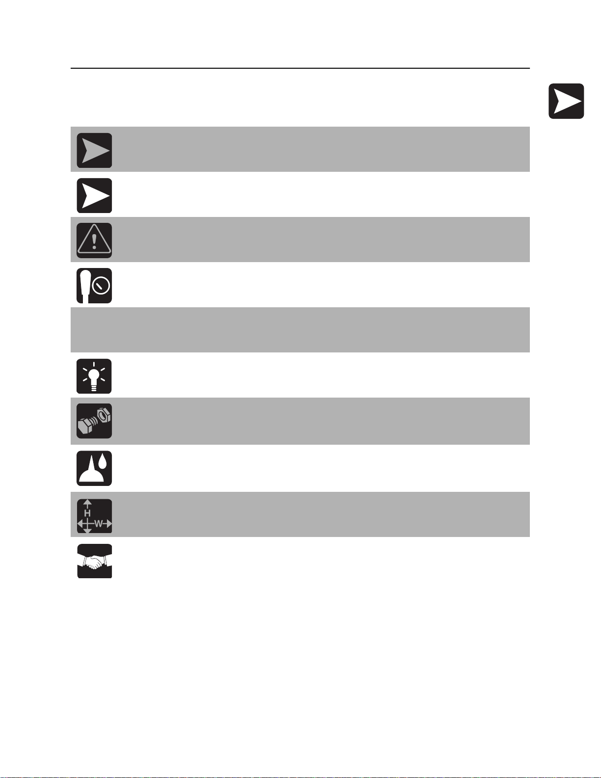
“Continued” Indicators
indicates that a procedure is continued on the next page.
CMW
Page 5

Overview - 4 8500 Tracking System Operator’s Manual
FCC Statement - Internal Transmitter
FCC Statement - Internal Transmitter
FCC ID: ITQ-8500TKR
IC: 3598A-8500TKR
This device complies with Part 15 of the FCC Rules. Operation is subject to the following two conditions:
(1) this device may not cause harmful interference, and (2) this device must accept any interference
received, including interference that may cause undesired operation.
To reduce potential radio interference to other users, the antenna type and its gain should be so chosen
that the equivalent isotropically radiated power (e.i.r.p.) is not more than that permitted for successful
communication.
Changes or modifications not expressly approved by The Charles Machine Works, Inc. could void the
user’s authority to operate the equipment.
N 16819
RF Exposure Statement
This equipment has been tested for RF exposure according to FCC rules for body-worn
equipment. The equipment must be operated in accordance with manufacturer expectations to insure
RF exposure compliance.
In order to comply with RF exposure requirements during normal operation, this device must be held in
front of the body horizontally. The antenna must be vertical in line with the body with at least 4” (100 mm)
separation distance from the body.
Note: This equipment has been tested and found to comply with the limits for a Class B digital device,
pursuant to Part 15 of the FCC rules. These limits are designed to provide reasonable protection against
harmful interference in a residential installation. This equipment generates, uses and can radiate radio
frequency energy and, if not installed and used in accordance with the instructions, may cause harmful
interference to radio communications. However, there is no guarantee that interference will not occur in a
particular installation. If this equipment does cause harmful interference to radio or television reception,
which can be determined by turning the equipment off and on, the user is encouraged to try to correct the
interference by one or more of the following measures:
• Reorient or relocate the receiving antenna.
• Increase the separation between the equipment and receiver.
• Connect the equipment into an outlet on a circuit different from that to which the receiver is connected.
• Consult the dealer or an experienced radio/TV technician for help.
CMW
Page 6

8500 Tracking System Manual Foreword - 5
Foreword
This manual is an important part of your equipment. It provides safety information and operation
instructions to help you use and maintain your Ditch Witch equipment.
Read this manual before using your equipment. Keep it with the equipment at all times for future reference.
If you sell your equipment, be sure to give this manual to the new owner.
If you need a replacement copy, contact your Ditch Witch dealer. If you need assistance in locating a
dealer, visit our website at www.ditchwitch.com or write to the following address:
The Charles Machine Works, Inc.
Attn: Marketing Department
PO Box 66
Perry, OK 73077-0066
USA
The descriptions and specifications in this manual are subject to change without notice. The Charles
Machine Works, Inc. reserves the right to improve equipment. Some product improvements may have
taken place after this manual was published. For the latest information on Ditch Witch equipment, see your
Ditch Witch dealer.
Thank you for buying and using Ditch Witch equipment.
CMW
Page 7

Foreword - 6 8500 Tracking System Operator’s Manual
8500 Tracking System
Operator’s Manual
Issue number 2.0/OM-5/10
Part number 053-1254
Copyright 2008, 2009, 2010
by The Charles Machine Works, Inc.
, Ditch Witch, CMW, AutoCrowd, Jet Trac, Roto Witch, Subsite, Fluid Miser,
Power Pipe, Super Witch, Pierce Airrow, The Underground, The Underground Authority Worldwide, and
Zahn are registered trademarks of The Charles Machine Works, Inc.
CMW
Page 8
8500 Tracking System Operator’s Manual Contents - 7
Contents
Overview
machine serial number, information about the type of work this machine is designed
to perform, basic machine components, and how to use this manual
Foreword
part number, revision level, and publication date of this manual, and factory contact
information
Safety
machine safety alerts and emergency procedures
Controls
machine controls and how to use them
System Operation
procedures for tracking beacon signals
Tracking Concepts
basic information for tracking beacon signals
Systems and Equipment
status messages, beacon information, TMS Plus interface instructions
1
5
9
13
33
47
51
Service
service intervals and instructions for this machine
Specifications
machine specifications including weights and measurements
Support
the warranty policy for this machine, and procedures for obtaining warranty
consideration and training
61
65
71
CMW
Page 9

Contents - 8 8500 Tracking System Operator’s Manual
CMW
Page 10

8500 System Operator’s Manual Safety - 9
Safety
Chapter Contents
Guidelines . . . . . . . . . . . . . . . . . . . . . . . . . . . . . . . . 10
Safety Alert Classifications . . . . . . . . . . . . . . . . . . 11
Safety Alerts . . . . . . . . . . . . . . . . . . . . . . . . . . . . . . 12
CMW
Page 11

Safety - 10 8500 System Operator’s Manual
Guidelines
Guidelines
Follow these guidelines before operating any jobsite equipment:
• Complete proper training and read operator’s manual before using equipment.
• Contact One-Call (888-258-0808) and any utility companies which do not subscribe to One-Call. Have
all underground pipes and cables located and marked before operating equipment. If you damage a
utility, contact utility company.
• Classify jobsite based on its hazards and use correct tools and machinery, safety equipment, and work
methods for jobsite.
• Mark jobsite clearly and keep spectators away.
• Wear personal protective equipment.
• Review jobsite hazards, safety and emergency procedures, and individual responsibilities with all
personnel before work begins.
• Replace missing or damaged safety signs.
• Use equipment carefully. Stop operation and investigate anything that does not look or feel right.
• Contact your equipment dealer if you have any question about operation, maintenance, or equipment
use.
CMW
Page 12
8500 System Operator’s Manual Safety - 11
Safety Alert Classifications
Safety Alert Classifications
These classifications and the icons defined on the following pages work together to alert you to situations
which could be harmful to you, jobsite bystanders or your equipment. When you see these words and
icons in the book or on the unit, carefully read and follow all instructions. YOUR SAFETY IS AT STAKE.
Watch for the three safety alert levels: DANGER, WARNING and CAUTION. Learn what each level
means.
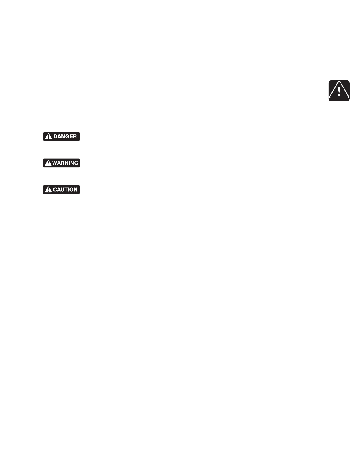
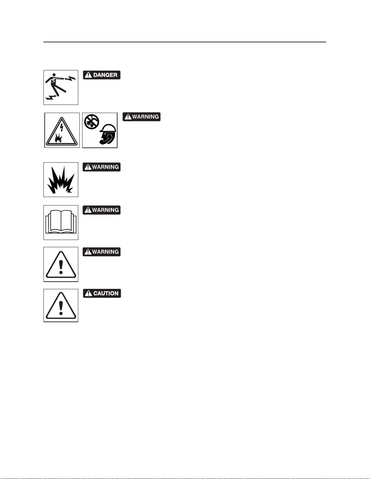
indicates an imminently hazardous situation which, if not avoided, will result in death or
serious injury.
indicates a potentially hazardous situation which, if not avoided, could result in death or
serious injury.
indicates a potentially hazardous situation which, if not avoided, may result in minor or
moderate injury.
Watch for two other words: NOTICE and IMPORTANT.
NOTICE can keep you from doing something that might damage the unit or someone's property. It can also
alert you against unsafe practices.
IMPORTANT can help you do a better job or make your job easier in some way.
CMW
Page 13
Safety - 12 8500 System Operator’s Manual
Safety Alerts
Safety Alerts
Electric shock. Contacting electric lines will cause death or serious injury.
Know location of lines and stay away.
Jobsite hazards could cause death or serious injury. Use
correct equipment and work methods. Use and maintain proper safety
equipment.
Explosion possible. Serious injury or equipment damage could occur.
Follow directions carefully.
Incorrect procedures could result in death, injury, or property damage.
Learn to use equipment correctly.
Moving traffic - hazardous situation. Death or serious injury could result.
Avoid moving vehicles, wear high visibility clothing, post appropriate warning signs.
Potential radio frequency (RF) hazard. Operating this device within 4” (100
mm) of your body may cause RF exposure levels to exceed FCC RF exposure limits and
should be avoided.
CMW
Page 14

8500 Tracking System Operator’s Manual Controls - 13
Controls
Chapter Contents
8500TK . . . . . . . . . . . . . . . . . . . . . . . . . . . . . . . . . . 14
• Icons . . . . . . . . . . . . . . . . . . . . . . . . . . . . . . . . . . . . . . . . . . . . . . . . . . . 14
• Buttons . . . . . . . . . . . . . . . . . . . . . . . . . . . . . . . . . . . . . . . . . . . . . . . . . 17
• Menu . . . . . . . . . . . . . . . . . . . . . . . . . . . . . . . . . . . . . . . . . . . . . . . . . . 19
8500D . . . . . . . . . . . . . . . . . . . . . . . . . . . . . . . . . . . 23
• Icons . . . . . . . . . . . . . . . . . . . . . . . . . . . . . . . . . . . . . . . . . . . . . . . . . . . 23
• Buttons . . . . . . . . . . . . . . . . . . . . . . . . . . . . . . . . . . . . . . . . . . . . . . . . . 25
• Menu . . . . . . . . . . . . . . . . . . . . . . . . . . . . . . . . . . . . . . . . . . . . . . . . . . 28
CMW
Page 15
Controls - 14 8500 Tracking System Operator’s Manual
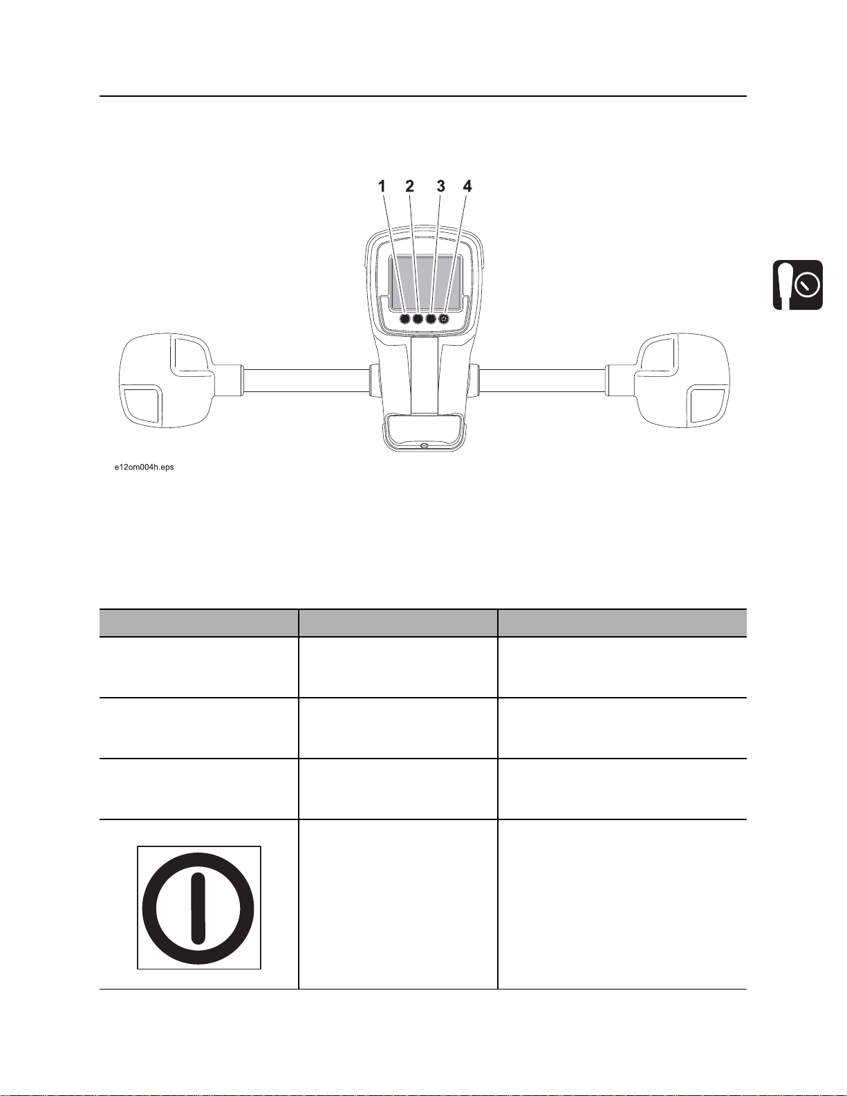
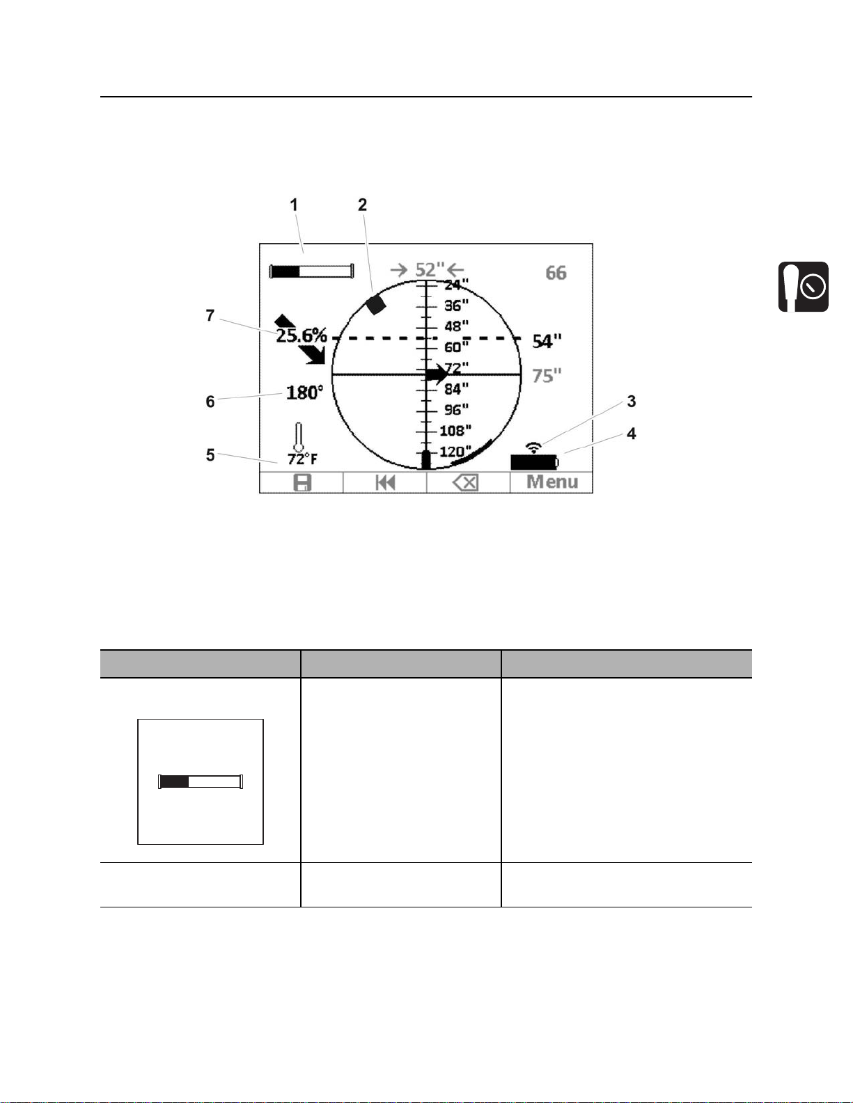
8500TK
8500TK
Icons
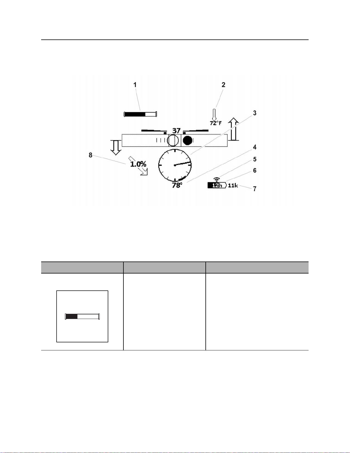
1. Beacon battery life indicator
2. Beacon temperature
3. Beacon roll indicator
4. Beacon roll value
Item Description Notes
1. Beacon battery life
indicator
c00ic072t.eps
Graphically indicates battery
life remaining.
If beacon is within 5 minutes
of entering sleep mode, a
countdown timer will appear
below icon.
An “L” appears in the icon if a
Lithium battery is installed.
5. Communication indicator
6. Tracker battery life indicator
7. Frequency indicator
8. Beacon pitch
CMW
Page 16
8500 Tracking System Operator’s Manual Controls - 15
8500TK
Item Description Notes
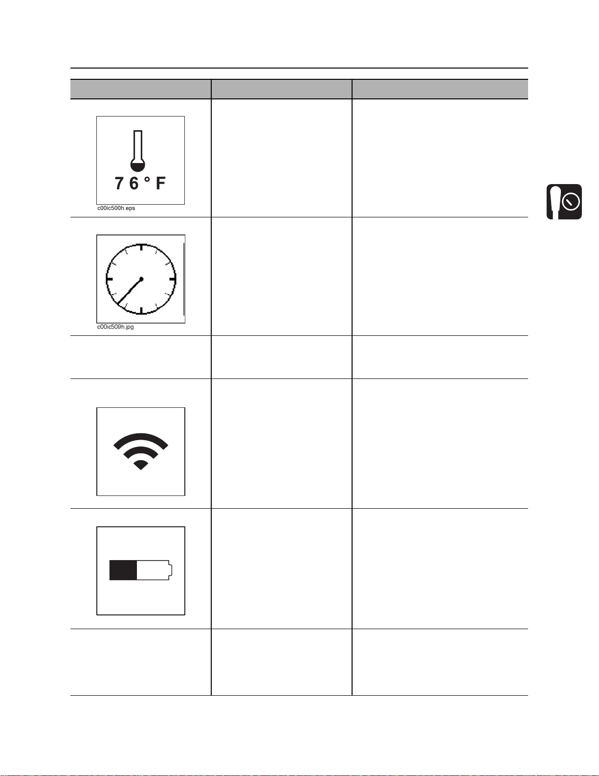
2. Beacon temperature Displays beacon temperature
and flashes if temperature
becomes too high.
Icon darkens as temperature
rises and temperature is
displayed numerically below
the icon.
3. Beacon roll indicator Graphically indicates
beacon’s roll position.
4. Beacon roll value Numerically displays
beacon’s roll position in
degrees, minutes or hours.
5. Communication
indicator
Indicates tracker is
transmitting.
IMPORTANT: An audible warning is
activated when beacon temperature is
155°F (68°C).
c00ic075t.eps
6. Tracker battery Indicates amount of battery
power remaining for the
tracker.
Flashes when batteries need
to be replaced.
c00ic076t.eps
7. Frequency indicator Displays “11k” when high
frequency beacon is selected.
Displays “2k” when low
frequency beacon is selected.
When using Li-ion smart battery pack,
the estimated time remaining appears
in the battery icon.
CMW
Page 17
Controls - 16 8500 Tracking System Operator’s Manual
8500TK
Item Description Notes
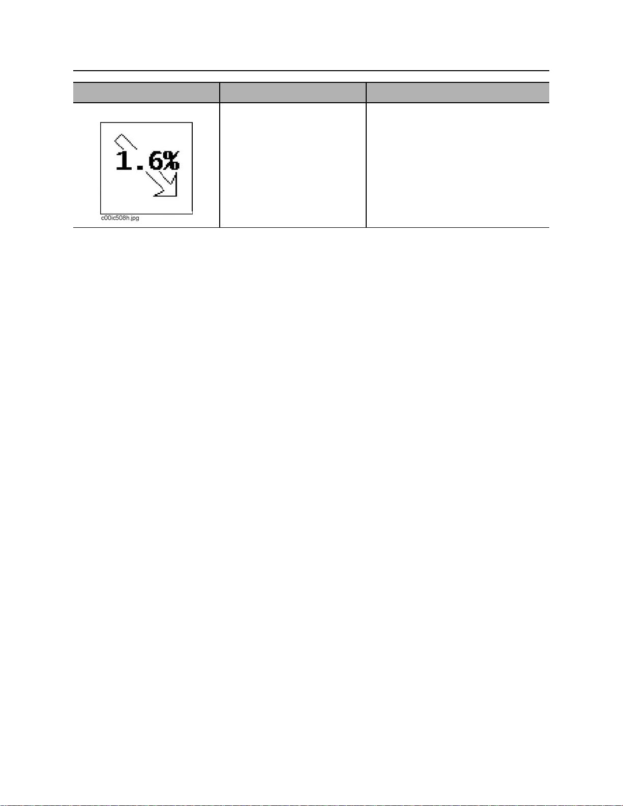
8. Beacon pitch Displays pitch of beacon in
percent grade or degrees.
The arrow behind the value
indicates whether pitch is
positive or negative.
CMW
Page 18
8500 Tracking System Operator’s Manual Controls - 17
8500TK
Buttons
Overview
1. Soft button
2. Soft button
Item Description Notes
1. Soft button Function depends on
selected mode and is
indicated above button.
2. Soft button Function depends on
selected mode and is
indicated above button.
3. Soft button Function depends on
selected mode and is
indicated above button.
4. Power button To turn on, press once.
To turn off, press for 2
seconds.
3. Soft button
4. Power button
Button is also used to access quick
functions.
Button is also used for quick
functions.
Button is also used for quick
functions.
Button is also used for quick
functions.
si1017a-d.eps
CMW
Page 19

Controls - 18 8500 Tracking System Operator’s Manual
8500TK
Quick Functions
Contrast Adjustment
To adjust contrast, press and hold left button (1) and press button 2 to darken/increase contrast or button 3
to lighten/lessen contrast.
Backlight Toggle
To turn backlight on and off, press and hold left button (1) and press power (4) button. Don’t press power
button for more than 2 seconds to avoid turning unit off.
CMW
Page 20
8500 Tracking System Operator’s Manual Controls - 19
8500TK
Menu
Overview
12
3
1
2
4
3
+
-
6
1. Drill-Thru mode
2. Beacon settings
3. Radio options
Item Description Notes
1. Drill-Thru mode Highlight icon and press
select to enter the drill-thru
mode.
501
0.1%
5
4. System settings
5. Display settings
6. Service menu
See “Drill-Thru Mode” on page 43.
4
2. Beacon settings Highlight icon and press
select to enter the “beacon
settings” menu.
See “Beacon Settings” on page 21.
CMW
Page 21
Controls - 20 8500 Tracking System Operator’s Manual
8500TK
Item Description Notes
3. Radio options Highlight icon and press
select to enter the “radio
options” mode.
4. Service menu Highlight icon and press
select to enter “service
menu.”
5. Display settings Highlight icon and press
select to enter the “display
settings” menu.
See “Radio Options” on page 22.
See “Service Menu” on page 22.
See “Display Settings” on page 21.
6. System settings Highlight icon and press
select to enter the “system
settings” menu.
+
-
c00ic086t.eps
CMW
See “System Settings” on page 22.
Page 22
8500 Tracking System Operator’s Manual Controls - 21
8500TK
Descriptions
Display Settings
Description Notes
LCD brightness Controls LCD backlight intensity.
Available settings: 0 (off) to 100 (brightest, default).
LCD contrast Controls contrast of LCD.
Available settings: -20 (lighter) to 20 (darker), 0 is default.
Units Controls displayed units of depth values, temperatures and other
numbers.
Available distance settings: inches, ft in (default), decimal ft, meters,
centimeters.
Depth disp. time Controls how long depth information is locked on the screen after
pressing depth button.
Available settings: 0-60 seconds, 5 is default.
Roll angle disp. Controls display of numerical value of the roll indicator.
Available settings: off (default), degrees, minutes, hours.
Pitch disp. Controls display of beacon pitch indicator.
Available settings: percent (default), degrees.
Beacon Settings
Description Notes
Beacon freq. Sets tracker receiving frequency.
Available settings: high (default), low.
Beacon calibration Calibrates tracker to beacon.
Roll calibration Sets roll position for beacon equivalent to bit pointing up (12 o’clock, 0
minutes, 0°).
Pitch calibration Sets 0.0% pitch position for grade beacon (1.0% limit).
Depth adjustment Tracker automatically compensates for the 12” (30 cm) the tracker is
above the ground when the grade pole is zeroed.
Changes built-in adjustment of depth measurements.
CMW
Page 23

Controls - 22 8500 Tracking System Operator’s Manual
8500TK
Radio Options
Description Notes
Radio power Turns radio on and off.
Available settings: on (default), off.
Channel Sets telemetry channel
Available settings: 1 (default) through 15
OnGrade channel Sets channel for OnGrade pole communication
Available settings: 1 (default) through 3
Tracker Control Enables or disables thrust and rotation of drilling unit.
Available settings: Rig ON, Rig OFF (default).
Tracker Control code Selects code for Tracker Control feature corresponding to code on
display.
System Settings
IMPORTANT: Warning sounds such as beacon temperature alert are always audible.
Description Notes
Language Controls user interface language. Turn tracker off and on for language
setting to change.
Tracker sleep Controls tracker sleep feature.
Available settings: enabled (default), disabled.
Volume Controls volume of the signal sound and sound effects.
Available settings: mute, low, med, high (default).
Battery status Displays available battery information. Displays estimated runtime
remaining and battery health when using optional Li-ion smart battery
pack.
Service Menu
Description Notes
About Lists hardware and software versions, serial number, and copyright
information.
Uptime Displays uptime and life timers.
Support Enters support menu.
Factory Enters factory menu. Password protected.
CMW
Page 24
8500 Tracking System Operator’s Manual Controls - 23
8500D
8500D
Icons
1. Beacon battery life indicator
2. Beacon roll indicator
3. Communication indicator
4. Display battery life indicator
Item Description Notes
1. Beacon battery life
indicator
c00ic072t.eps
2. Beacon roll indicator Graphically indicates
Graphically indicates battery
life remaining.
If beacon is within 5 minutes
of entering sleep mode, a
countdown timer will appear
below icon.
An “L” appears in the icon if a
Lithium battery is installed.
beacon’s roll position.
5. Beacon temperature
6. Beacon roll value
7. Beacon pitch
CMW
Page 25

Controls - 24 8500 Tracking System Operator’s Manual
8500D
Item Description Notes
3. Communication
indicator
c00ic075t.eps
4. Display battery life
indicator
Indicates tracker and display
are communicating properly.
Indicates amount of battery
power remaining for the
display.
Flashes when batteries need
to be replaced.
c00ic076t.eps
5. Beacon temperature Displays beacon temperature
and flashes if temperature
becomes too high.
If unit is connected to external power,
indicator changes to a plug.
Icon darkens as temperature
rises and temperature is
displayed numerically below
the icon.
6. Beacon roll value Displays numeric value in
degrees, minutes or hours.
7. Beacon pitch Displays pitch of beacon in
percent grade or degrees.
The arrow behind the value
indicates whether pitch is
positive or negative.
CMW
Page 26

8500 Tracking System Operator’s Manual Controls - 25
8500D
Buttons
Overview
1. Save button
2. Review button
IMPORTANT:
• Some icons and functions will change when display is properly connected to TMS Plus. These are
shown and explained in the following table.
• SD card must be installed and have active log file or display must be connected to TMS Plus to
store, review or delete logged data.
3. Delete button
4. Power button
CMW
Page 27

Controls - 26 8500 Tracking System Operator’s Manual
8500D
Item Description Notes
1. Save button
Send button
2. Review button
Press to save data for current
pipe.
When connected to TMS
Plus or OGMS:
Press to send data for current
pipe to TMS Plus or OGMS.
Press to review previous pipe
data.
Press again to review pipe
before that.
IMPORTANT: Display must have
received a depth reading from tracker
to save.
Recall button
CMW
When connected to TMS
Plus:
Press to review target
information for next pipe.
When connected to OGMS:
No function.
Page 28

8500 Tracking System Operator’s Manual Controls - 27
8500D
Item Description Notes
3. Delete button Press to delete previous pipe
data.
4. Power/Menu button To turn on, press once.
To turn off, press for 2
seconds.
si1017a-d.eps
Press button less than 2 seconds to
access menu.
Quick Functions
Contrast Adjustment
To adjust contrast, press and hold left button (1) and press button 2 to darken/increase contrast or button 3
to lighten/lessen contrast.
Backlight Toggle
To turn backlight on and off, press and hold left button (1) and press power (4) button. Don’t press power
button for more than 2 seconds to avoid turning unit off.
CMW
Page 29

Controls - 28 8500 Tracking System Operator’s Manual
8500D
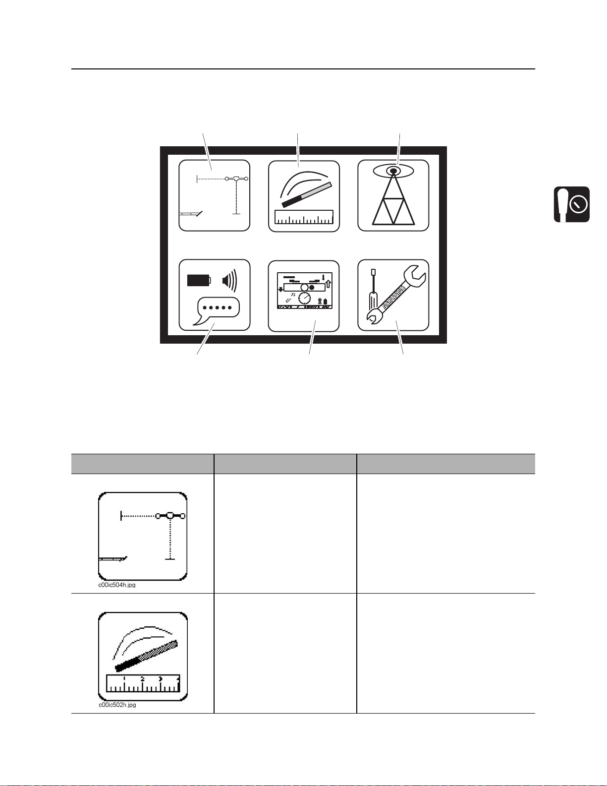
Menu
Overview
1. File management
2. Time/Date settings
3. Radio options
Item Description Notes
1. File Management Highlight icon and press
select to start new job or
review saved job files.
2. Time/Date settings Highlight icon and press
select to enter the “time/date
settings” menu.
4. System settings
5. Display settings
6. Service menu
See “File Management” on page 31.
See “Date/Time Settings” on page 32.
CMW
Page 30

8500 Tracking System Operator’s Manual Controls - 29
8500D
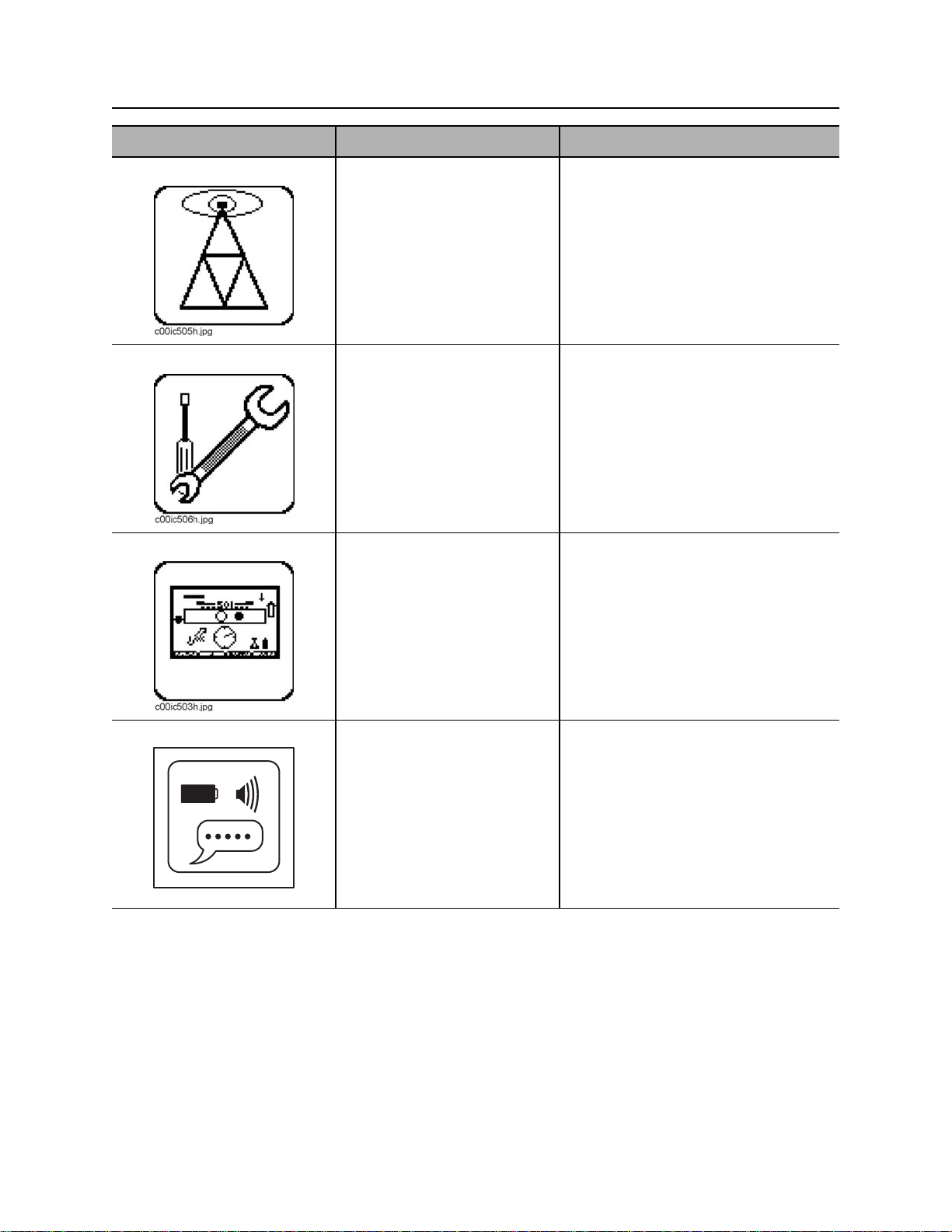
Item Description Notes
3. Radio options Highlight icon and press
select to enter the “radio
options” mode.
4. System settings Highlight icon and press
select to enter the “system
settings” menu.
+
-
c00ic086t.eps
5. Display settings Highlight icon and press
select to enter the “display
settings” menu.
See “Radio Options” on page 31.
See “System Settings” on page 32.
See “Display Settings” on page 30.
6. Service menu Highlight icon and press
select to enter “service
menu.”
See “Service Menu” on page 32.
CMW
Page 31

Controls - 30 8500 Tracking System Operator’s Manual
8500D
Descriptions
Display Settings
Description Notes
LCD brightness Controls brightness.
Available settings: 0 (off) to 100 (brightest, default).
LCD contrast Controls contrast of LCD.
Available settings: -20 (lighter) to 20 (darker), 0 is default.
Units Controls displayed units of depth values, temperatures and other
numbers.
Available distance settings: inches, ft in (default), decimal feet, meters,
centimeters.
Depth disp. time Controls how long depth information is locked on the screen after depth
is received from tracker.
Available settings: 0-60 seconds, 5 is default.
Log review time Controls how long log information is locked onscreen after pressing
any logging button.
Available settings: 0-60 seconds, 5 is default.
Roll angle disp. Controls display of numerical portion of the roll indicator.
Available settings: off (default), degrees, minutes, hours.
Pitch disp. Controls display of beacon pitch indicator.
Available settings: percent (default), degrees.
CMW
Page 32

8500 Tracking System Operator’s Manual Controls - 31
8500D
File Management
Description Notes
Active file Indicates name of log file that is currently active.
Load file Displays a list of log files currently on the SD card. Select a file to make
it the active log file.
Create file Creates a new log file and makes it the active file.
Delete file Displays a list of log files currently on the SD card. Select a file to
delete it.
Delete all Deletes all files on the SD card and formats it for use.
Make .750 files Creates .750 files out of all log files on the SD card for import into TMS
Plus. Select this before removing SD card and importing data into TMS
Plus. See “Data Transfer” on page 59.
Upload all Uploads all log files to TMS Plus when connected through USB cable.
See “Data Transfer” on page 59. Follow prompts.
Auto-Log Stores a log point every time depth information is sent from tracker.
Options: disabled (default), enabled.
IMPORTANT: Display must have SD card installed with valid log file
active or be connected to TMS Plus.
Radio Options
IMPORTANT: In order for information on tracker and display to match, ensure units are set on the same
channel.
Description Notes
Channel Sets telemetry channel
Available settings: 1 (default) through 15
Tracker Control code Displays code for Tracker Control feature.
CMW
Page 33

Controls - 32 8500 Tracking System Operator’s Manual
8500D
System Settings
Description Notes
Connect to TMS Plus Activates TMS Plus connected mode.
Connect to OGMS Activates OGMS connected mode.
Language Controls displayed user interface language. Turn display off and on for
language setting to change.
Date/Time Settings
Description Notes
Time format Controls display of time.
Available settings: 12 (default), 24
Year Sets year.
Month Sets month.
Day Sets day.
Hour Sets hour.
Minutes Sets minutes.
Service Menu
Description Notes
About Lists hardware and software versions, serial number, and copyright
information.
Uptime Displays uptime and life timers.
Support Enters support menu.
Factory Enters factory menu. Password protected.
CMW
Page 34

8500 Tracking System Operator’s Manual System Operation - 33
System Operation
Chapter Contents
Beacon Tracking Overview . . . . . . . . . . . . . . . . . . 34
Setup . . . . . . . . . . . . . . . . . . . . . . . . . . . . . . . . . . . . 35
Walkover Location Mode . . . . . . . . . . . . . . . . . . . . 36
• Locate Screen . . . . . . . . . . . . . . . . . . . . . . . . . . . . . . . . . . . . . . . . . . . 36
• Procedure . . . . . . . . . . . . . . . . . . . . . . . . . . . . . . . . . . . . . . . . . . . . . . . 38
• Depth Screen . . . . . . . . . . . . . . . . . . . . . . . . . . . . . . . . . . . . . . . . . . . . 40
• Displayed Features . . . . . . . . . . . . . . . . . . . . . . . . . . . . . . . . . . . . . . . 41
• Sample Screens . . . . . . . . . . . . . . . . . . . . . . . . . . . . . . . . . . . . . . . . . . 42
Drill-Thru Mode . . . . . . . . . . . . . . . . . . . . . . . . . . . 43
• Drill-Thru View Screen . . . . . . . . . . . . . . . . . . . . . . . . . . . . . . . . . . . . . 43
• Beacon View Screen . . . . . . . . . . . . . . . . . . . . . . . . . . . . . . . . . . . . . . 44
• Procedure . . . . . . . . . . . . . . . . . . . . . . . . . . . . . . . . . . . . . . . . . . . . . . . 45
• Sample Screens . . . . . . . . . . . . . . . . . . . . . . . . . . . . . . . . . . . . . . . . . . 45
CMW
Page 35

System Operation - 34 8500 Tracking System Operator’s Manual
Beacon Tracking Overview
Beacon Tracking Overview
Potential radio frequency (RF) hazard. Operating this device within 4”
(100 mm) of your body may cause RF exposure levels to exceed FCC RF exposure limits
and should be avoided.
NOTICE:
• This device must not be co-located with any other radio transmitter.
• The maximum antenna gain is 2.5 dBi.
The tracker has two modes: walkover location and drill-thru. Use walkover location mode to find position of
the beacon. Once tracker is in or near the beacon plane, select the depth view to determine the depth and
the left/right offset. With tracker in front of and parallel to beacon, press the L/R button while in the main
locate view to see the projected path of the beacon. In drill-thru mode, the tracker is placed along the
intended bore path and provides the necessary steering corrections for the drilling unit operator to drill that
path.
CMW
Page 36

8500 Tracking System Operator’s Manual System Operation - 35
Setup
Setup
1. Install battery in beacon.
2. Place beacon in beacon housing away from
metal objects.
3. Set up beacon and tracker 10’/305 cm (A)
apart, as shown.
4. Select “Beacon Calibration” in “Beacon
Settings” menu and follow prompts. See
page 21.
IMPORTANT:
• Error conditions will be reported onscreen below diagram.
• Pressing “clear” button will restore factory default. This will not provide accurate depth and
offset measurements. Calibrate beacon and tracker properly.
• Pressing “cancel” will exit calibration menu without changing tracker’s calibration.
• If using a dual-frequency beacon, calibrate both frequencies.
5. Select “Roll Calibration” in “Beacon Settings” menu and follow prompts.
6. Select “Pitch Calibration” in “Beacon Settings” menu and follow prompts.
7. Select “Depth Adjustment” in “Beacon Settings” menu and follow prompts.
CMW
Page 37

System Operation - 36 8500 Tracking System Operator’s Manual
Walkover Location Mode
Walkover Location Mode
Locate Screen
1. Field balance bar
2. Signal strength
3. Locate arrows
Item Description Notes
1. Field Balance Bar Indicates tilt of tracker (hollow
circle) and magnetic field
balance (solid circle).
2. Signal Strength Average signal strength is
displayed numerically.
Gain and signal strength bars
are also displayed to each
side of numeric value.
4. L/R button
5. Send button
6. Depth screen button
Beacon is properly located when both
circles are located in the square in the
center of the bar and fore/aft arrows
form diamonds.
Bars get longer as number gets
smaller.
CMW
Page 38

8500 Tracking System Operator’s Manual System Operation - 37
Walkover Location Mode
Item Description Notes
3. Locate Arrows Indicate fore-aft direction to
move antenna pod to locate
beacon plane.
Arrows change to diamonds
when antenna pods are in
beacon plane.
4. L/R Button Press and hold to display
projected direction.
5. Send Button Press to send range to
remote display.
6. Depth Screen Button Press to enter depth screen.
Longer arrows indicate the tracker is a
greater distance from beacon plane.
Advanced depth features are
available when both arrows or
diamonds are solid.
Tracker pods must be parallel with
beacon. See “Projected Direction” on
page 39.
The displayed value is measured from
the center of the tracker, along the
centerline of the antenna pods,
directly under the tracker.
CMW
Page 39

System Operation - 38 8500 Tracking System Operator’s Manual
Walkover Location Mode
Procedure
Incorrect procedures could result in death, injury, or property damage.
Learn to use equipment correctly.
NOTICE: Do not stand or walk over the bore path while drill string is moving (during
drilling and backreaming).
The 8500 tracking system provides three ways to locate a beacon using walkover location mode. Choose
which method to use based on your tracking situation.
Single-Point Location
If concerned with ghost signals or bore path is
unknown, use single-point location to find general
location of beacon.
1. Position tracker parallel (shown) to suspected
bore path.
2. Walk along bore path until solid and hollow
circles are approximately centered in field
balance bar.
3. Rotate tracker 90° so that tracker is
perpendicular to bore path.
4. Move tracker left or right to center both circles.
Tracker is now roughly over the beacon.
5. To locate beacon more precisely, follow peak or advanced location procedure.
Peak Location
If beacon depth is greater than 30’ (9 m), use peak
location procedure to position tracker over beacon.
This procedure works well at any depth.
1. With tracker perpendicular to bore path
(shown), follow locate arrows to beacon plane.
2. Move tracker laterally until signal strength is
minimized.
3. Place tracker on the ground and press SEND
button to take depth reading and send it to
display.
The signal strength reading is the approximate distance from the beacon in inches. A reading of 122
means the tracker is 122” (3.1 m) from the beacon. This reading reflects how many inches the tracker is
from the beacon regardless of the units setting in the display menu.
CMW
Page 40

8500 Tracking System Operator’s Manual System Operation - 39
Walkover Location Mode
Advanced Location
If beacon depth is less than 30’ (9 m), use advanced
location procedure to position tracker over beacon.
1. With tracker perpendicular to bore path, follow
locate arrows to beacon plane.
2. Place tracker on the ground and press DEPTH
button. If desired, move tracker side-to-side
until offset is at 0.
3. Press SEND button to take depth reading and
send it to display. Press and hold SEND button
for 1/2 second if 0.1” (1 cm) precision is
required.
Quick Range
To get a quick estimate of how far away the beacon is, press the SEND button while the tracker is in
walkover locate view. The average of the distance to the beacon for each pod will be displayed in place of
the signal strength.
Projected Direction
1. Hold down the L/R button to switch from foreaft arrows to left-right arrows.
2. Move approximately 10’ (3 m) in front of the
beacon position and rotate tracker until tracker
is parallel with bore path with left antenna pod
closer to drilling unit.
3. Align arrows to check beacon heading.
4. When arrows turn solid, the projected depth
will be displayed in a dotted box (shown
below) in place of the signal strength value.
CMW
Page 41

System Operation - 40 8500 Tracking System Operator’s Manual
Walkover Location Mode
Depth Screen
1. Tracker tilt indicator
2. Depth
3. Locate mode button
Item Description Notes
1. Tracker tilt indicator Graphically represents the tilt
of the tracker antenna pods
with a numeric reading to the
left of the visual
representation.
2. Depth Displays vertical depth
measurement.
3. Locate mode button Press to return to locate
screen.
4. View button Press to switch between
depth and side views.
4. View button
5. Send button
6. Left/right offset
CMW
Page 42

8500 Tracking System Operator’s Manual System Operation - 41
Walkover Location Mode
Item Description Notes
5. Send button Press to send depth to
remote display.
Press for 1/2 second to get
average with 0.1” (1 cm)
resolution and send depth to
display.
Continue pressing for
continuous average. Release
to send depth to display.
6. Left/right offset Indicates left/right offset with
respect to center of beacon
and middle of tracker handle.
Tracker provides both graphical and
numeric offset information.
Displayed Features
Advanced depth features (vertical depth, left/right offset, 0.1”/1 cm precision) are not available when any of
the following conditions are met:
• Beacon is more than 30’ (9 m) away from tracker
• Tracker tilt is greater than 20°
• Beacon pitch is greater than 10% and tracker tilt is greater than 5°
• Fore/aft arrows are hollow (tracker is outside the beacon plane)
CMW
Page 43

System Operation - 42 8500 Tracking System Operator’s Manual
Walkover Location Mode
Sample Screens
Depth screen, standard view
Beacon is pitched down at 0.5%, is offset from tracker 9” to the left and is 2’
3.3” deep. The tracker is level to the ground. Depth reading bar will become
solid as values are averaged. Once it is solid, the value is locked and sent to
remote display.
CMW
Depth screen, side view
Beacon is pitched down at 0.5%, is directly below the tracker and is 2’ 3” deep.
Page 44

8500 Tracking System Operator’s Manual System Operation - 43
Drill-Thru Mode
Drill-Thru Mode
Drill-Thru View Screen
1. Pitch
2. Horizontal distance
3. Current depth
1. Pitch Displays pitch of beacon in
percent grade or degrees.
The orientation of the icon
indicates whether pitch is
positive or negative.
2. Horizontal distance Displays distance from
beacon to tracker.
3. Current depth Displays current depth of
beacon relative to tracker
position.
4. Projected depth Displays the projected depth
when beacon reaches tracker
if current pitch is maintained.
5. Locate mode button Press to return to locate
mode.
4. Projected depth
5. Locate mode button
6. View button
6. View button Press to switch between drillthru and beacon view.
CMW
Page 45

System Operation - 44 8500 Tracking System Operator’s Manual
Drill-Thru Mode
Beacon View Screen
1. Horizontal distance
2. Direction indicator arrows
3. Signal strength
4. Steering correction arrow
5. Projected depth
1. Horizontal distance Displays distance from
beacon to tracker.
2. Direction indicator
arrows
3. Signal strength Displays numeric signal
4. Steering correction
arrow
5. Projected depth Displays the projected depth
6. Current depth Displays current depth of
Indicates beacon direction
relative to the tracker.
strength value.
Represents the direction of
steering correction needed.
when beacon reaches tracker
if current pitch is maintained.
beacon relative to tracker
position.
6. Current depth
7. Locate mode button
8. Current depth indicator
9. View button
Inward arrows mean the beacon is
approaching tracker and outward
arrows mean beacon is moving away.
CMW
Page 46

8500 Tracking System Operator’s Manual System Operation - 45
Drill-Thru Mode
7. Locate mode button Press to return to locate
mode.
8. Current depth indicator Indicates current position
relative to tracker.
9. View button Press to switch between drillthru and beacon view.
Procedure
Incorrect procedures could result in death, injury, or property damage.
Learn to use equipment correctly.
NOTICE:
• If location and depth are critical, confirm by hand-digging.
• Do not stand or walk over the bore path while drill string is moving (during drilling and backreaming).
1. Place tracker on the ground along intended bore path with left pod closest to drilling unit.
2. Drill as usual.
• While beacon is on the drilling unit side of tracker, a left/right steering correction arrow, current
depth, horizontal distance and projected depth are provided.
• After beacon passes under tracker, current depth and horizontal distance are provided. Projected
depth and the left/right steering arrow are no longer provided.
CMW
Page 47

System Operation - 46 8500 Tracking System Operator’s Manual
Drill-Thru Mode
Sample Screens
Drill-Thru View
Beacon is approaching tracker pitched down 11.2%. Beacon is 27” deep and the projected depth at
tracker is 30”. The horizontal distance to the tracker is 31”. The beacon must be steered to the right to
pass under the tracker as indicated by the arrow in the center of the Beacon View.
Beacon View
CMW
Page 48

8500 Tracking System Operator’s Manual System Operation - 47
Drill-Thru Mode
Drill-Thru View Beacon View
Beacon is approaching tracker pitched up 82.2%. Beacon is 36” deep and the projected depth at
tracker is 9”. The horizontal distance to the tracker is 32”. The beacon must be steered to the left to
pass under the tracker as indicated by the arrow in the center of the Beacon View. The arrow will get
longer as beacon gets farther off target and shorter as it gets closer to the target path.
Drill-Thru View
Beacon View
Beacon is past tracker pitched up 7.6%. Beacon is 27” deep and the horizontal distance from the
tracker is 86”.
CMW
Page 49

System Operation - 48 8500 Tracking System Operator’s Manual
Drill-Thru Mode
CMW
Page 50

8500 Tracking System Operator’s Manual Tracking Concepts - 47
Tracking Concepts
Chapter Contents
Theory of Operation . . . . . . . . . . . . . . . . . . . . . . . . 48
• System overview . . . . . . . . . . . . . . . . . . . . . . . . . . . . . . . . . . . . . . . . . 48
• Beacon plane . . . . . . . . . . . . . . . . . . . . . . . . . . . . . . . . . . . . . . . . . . . . 48
• Drill-Thru . . . . . . . . . . . . . . . . . . . . . . . . . . . . . . . . . . . . . . . . . . . . . . . 49
Ghost Signal Responses . . . . . . . . . . . . . . . . . . . . 50
CMW
Page 51

Tracking Concepts - 48 8500 Tracking System Operator’s Manual
Theory of Operation
Theory of Operation
System Overview
The 8500 tracking system uses a magnetic field generator in an 850 series beacon and two receiving
antenna pods in an 8500TK advanced tracker to determine beacon position. The tracker detects the
generated magnetic field and calculates the beacon’s position. Downhole information is relayed from the
beacon to the tracker. The tracker sends all received and calculated data to a remote display over a radio
link.
The dual antenna pod design provides the ability to approach the beacon location without encountering
ghost signals and can determine the beacon’s location and heading. When placed along the intended bore
path, the tracker can be used in Drill-Thru mode to provide the beacon’s current depth, projected depth at
the tracker location, horizontal distance (range) and horizontal steering correction.
Beacon Plane
The 8500TK locates the beacon plane
perpendicular to the center of the beacon. Once
the tracker is within range of the beacon and within
the beacon plane, the advanced depth calculations
of the tracker are enabled.
The beacon plane extends outward from the center
of the beacon and runs perpendicular to the
beacon as shown. Because of this, the ground
level location may be slightly in front of or behind
the true vertical position of the beacon’s center.
This is only apparent at extreme pitches and
increasing depths. For example, at 30’ (9 m) deep
and 10% pitch, the beacon plane and vertical plane
will be approximately 3’ (914 mm) apart at ground
level. The tracker calculates this difference and
presents it in the depth mode side view.
Beacon plane: side view
Beacon plane: top view
CMW
Page 52

8500 Tracking System Operator’s Manual Tracking Concepts - 49
Theory of Operation
Drill-Thru
The tracker calculates the beacon’s current depth, horizontal distance to the tracker and the predicted
depth at the tracker position. The tracker allows you to drill toward, under and away from the tracker while
providing depth and horizontal distance. The horizontal steering guides the operator to the intended bore
path, assuming a straight line along the tracker.
Sample beacon positions and resulting horizontal steering correction arrows.
The horizontal beacon plane (plane extended out at each end) must pass below both pods of the tracker
for drill-thru and projected depth numbers to be valid.
CMW
Page 53

Tracking Concepts - 50 8500 Tracking System Operator’s Manual
Ghost Signal Responses
Ghost Signal Responses
The locate arrows will change direction and point
away from the beacon (as shown) as the tracker
reaches a ghost signal. The distance from the
beacon plane to the ghost signals increases with
increasing depth.
To avoid locating ghost signals, rotate tracker
parallel to bore path (shown below) and watch the
solid circle in the field balance bar to get near the
beacon plane.
CMW
Page 54

8500 Tracking System Operator’s Manual Systems and Equipment - 51
Systems and Equipment
Chapter Contents
8500TK Status Messages . . . . . . . . . . . . . . . . . . . 52
8500D Status Messages . . . . . . . . . . . . . . . . . . . . 54
850 Beacons . . . . . . . . . . . . . . . . . . . . . . . . . . . . . . 55
• Sleep . . . . . . . . . . . . . . . . . . . . . . . . . . . . . . . . . . . . . . . . . . . . . . . . . . 55
• Dual frequency . . . . . . . . . . . . . . . . . . . . . . . . . . . . . . . . . . . . . . . . . . . 56
• Beacon throttle . . . . . . . . . . . . . . . . . . . . . . . . . . . . . . . . . . . . . . . . . . . 56
Li-ion Battery Pack . . . . . . . . . . . . . . . . . . . . . . . . 57
• Handling . . . . . . . . . . . . . . . . . . . . . . . . . . . . . . . . . . . . . . . . . . . . . . . . 57
• Charging . . . . . . . . . . . . . . . . . . . . . . . . . . . . . . . . . . . . . . . . . . . . . . . . 57
• Storage and Disposal . . . . . . . . . . . . . . . . . . . . . . . . . . . . . . . . . . . . . . 57
• LCD Indication . . . . . . . . . . . . . . . . . . . . . . . . . . . . . . . . . . . . . . . . . . . 58
• Battery Calibration . . . . . . . . . . . . . . . . . . . . . . . . . . . . . . . . . . . . . . . . 58
Data Transfer . . . . . . . . . . . . . . . . . . . . . . . . . . . . . 59
• Via cable . . . . . . . . . . . . . . . . . . . . . . . . . . . . . . . . . . . . . . . . . . . . . . . 59
• Via SD card . . . . . . . . . . . . . . . . . . . . . . . . . . . . . . . . . . . . . . . . . . . . . 59
CMW
Page 55

Systems and Equipment - 52 8500 Tracking System Operator’s Manual
8500TK Status Messages
8500TK Status Messages
Messages that communicate tracking system
information requiring user intervention or provide
important operation information appear in the top
center area of the display as shown.
Message Description Solution
SATURATED Signal from beacon or other noise is too large to
receive accurate signal.
Auto-Gain Active... Tracker’s auto-gain feature is active. Some
features and data values will stop updating until
auto-gain is complete.
Beacon Regulating Beacon is adjusting its output to provide a stable
signal. Depth values and beacon calibration are
unavailable while beacon is regulating.
BEACON BATT LOW Beacon battery voltage is low. Replace Power Stick or
BEACON POWER
LOW
TILT The tracker can no longer compensate for its
Beacon is close to being unable to provide a
stable output signal (is out of throttle).
position when calculating depth and offset
values. This occurs when the tilt of the tracker is
greater than 20° or the beacon pitch is greater
than 10% and the tracker tilt is greater than 5°.
Move tracker away from
beacon (at least 2’/610 mm)
or eliminate noise source.
Wait until message
disappears.
Wait until message
disappears.
lithium beacon batteries.
1. Replace Power Stick
beacon battery.
2. Use lithium beacon
battery.
3. Change to compatible
beacon housing or call
your Ditch Witch dealer.
Adjust tracker so it is closer
to level until message
disappears.
CMW
Page 56

8500 Tracking System Operator’s Manual Systems and Equipment - 53
8500TK Status Messages
Message Description Solution
No Comm Beacon signal is too weak to communicate with
tracker.
Out of Range Beacon is out of range for requested features.
Beacon must be within within 30’ (9 m) of
tracker for advanced features.
TRACKER BATT
LOW
F/A Align Tracker is too far out of the beacon plane to
Beacon Rolling... Beacon is rolling. Stop rolling beacon for more
BEACON MEM
ERROR
BEACON HOT Beacon is reporting temperature above 155°F
Tracker batteries are low and unit will soon shut
off.
enable advanced depth features while in depth
screen.
Calibration memory of beacon has been
corrupted.
(68°C). Permanent damage is imminent. An
audible alert will also sound.
1. Ensure beacon and
tracker are operating at
same frequency.
2. Move tracker within
range of beacon.
3. Ensure beacon is not
asleep.
Move tracker within 30’ (9
m) of beacon.
Replace tracker batteries.
Use fore/aft arrows to move
within beacon plane.
accurate readings.
Return beacon for service.
Stop rotation, pull back 3’
(915 mm) and continue
drilling fluid flow until
beacon cools down.
HIGH NOISE The signal-to-noise ratio is too low for tracker to
receive reliable data from beacon. Depth
calculation and beacon calibration are disabled.
Eliminate noise source or
switch beacon and tracker
operating frequencies.
CMW
Page 57

Systems and Equipment - 54 8500 Tracking System Operator’s Manual
8500D Status Messages
8500D Status Messages
Messages that provide important operation
information appear in the top center area of the
display as shown.
Message Description Solution
SATURATED Signal from beacon or other noise is too large to
receive accurate signal.
Auto-Gain Active... Tracker’s auto-gain feature is active. Some
features and data values will stop updating until
auto-gain is complete.
BEACON BATT LOW Beacon battery voltage is low. Replace Power Stick or
BEACON POWER
LOW
No Comm Beacon signal is too weak to communicate with
Beacon is close to being unable to provide a
stable output signal (is out of throttle).
tracker.
Move tracker away from
beacon (at least 2’/610 mm)
or eliminate noise source.
Wait until message
disappears.
lithium beacon batteries.
1. Replace Power Stick
beacon battery.
2. Use lithium beacon
battery.
3. Change to compatible
beacon housing or call
your Ditch Witch dealer.
1. Ensure beacon and
tracker are operating at
same frequency.
2. Move tracker within
range of beacon.
DISPLAY BATT LOW Display batteries are low and unit will soon shut
off.
Beacon Rolling... Beacon is rolling. Stop rolling beacon for more
BEACON MEM
ERROR
CMW
Calibration memory of beacon has been
corrupted.
Replace display batteries.
accurate readings.
Return beacon for service.
Page 58

8500 Tracking System Operator’s Manual Systems and Equipment - 55
850 Series Beacons
Message Description Solution
BEACON HOT Beacon is reporting temperature above 155°F
(68°C). Permanent damage is imminent.
850 Series Beacons
Sleep
850 series beacons enter sleep (power-saving)
mode after 20 minutes of inactivity. Rotate the
beacon at least 3 times at 1 rotation per second to
wake the beacon.
To enter Express Sleep mode, roll beacon to the
Express Sleep window (shown) and leave it
inactive. Beacon will enter power-saving mode
after only 5 minutes.
Stop rotation, pull back 3’
(915 mm) and continue
drilling fluid flow until
beacon cools down.
CMW
Page 59

Systems and Equipment - 56 8500 Tracking System Operator’s Manual
850 Series Beacons
Dual Frequency
Select operating frequency when batteries are inserted or downhole.
Select at Power Up
The orientation of the flat top on the forward isolator
when batteries are installed determines frequency.
• If flat top (shown) is up, beacon will operate at
11.2 kHz.
• If flat top is down, beacon will operate at 1.75
kHz.
Switch Downhole
1. Allow the beacon to enter sleep mode.
2. Wake the beacon within one minute of entering
sleep mode and beacon will switch frequencies.
Beacon Throttle
The beacon continuously monitors and adjusts its output power in order to maintain a constant signal
strength. Beacon housing properties, battery chemistry and battery voltage impact the beacon’s ability to
maintain this output. Beacon throttle is a measure of the remaining time a beacon will be able to maintain
its output level.
CMW
Page 60

8500 Tracking System Operator’s Manual Systems and Equipment - 57
850 Series Beacons
Li-ion Battery Pack
Handling
• Avoid shorting the battery.
• Do not immerse in water.
• Do not disassemble or deform the battery. Never use a battery that appears to have suffered abuse.
• Do not expose battery to fire. Do not dispose of the battery in fire.
• Avoid excessive physical shock or vibration.
Charging
• Battery must be charged in an appropriate charger only. Never use a modified or damaged charger.
• Charge at 32°F to 113°F (0°C to 45°C) in less than 80% relative humidity.
Storage and Disposal
• Dispose of in accordance with local regulations.
• Store in a cool, dry, and well-ventilated area. Storage limits: -4°F to 140°F (-20°C to 60°C), <80%
relative humidity.
• For best results, store battery pack in an environment free from corrosive gas at a temperature less
than 70°F (21°C). Extended exposure to temperatures above 113°F (45°C) could degrade battery
performance and life.
• If storing battery pack for an extended period, charge or discharge to pack to 30-50% remaining
capacity. This will give at least 6 months of shelf life at room temperature before electronics go into
shutdown mode. Charge the battery every 6 months if longer storage is required.
• After the battery has self-discharged for an extended time, the electronics will disconnect from the
internal cells. The battery will exist in this storage state for approximately one year at room
temperature before the cells discharge to the point beyond which they should not be charged.
CMW
Page 61

Systems and Equipment - 58 8500 Tracking System Operator’s Manual
850 Series Beacons
LCD Indication
The battery displays its current charge condition.
Each LCD segment represents 20% of the battery
capacity.
If the battery pack has been fully discharged, there
will be no LCD indication.
Capacity LCD Segments
Battery Calibration
Calibration adjusts the battery’s fuel gauge to maintain an acceptable level of accuracy. If the remaining
time or percentage appears to be inaccurate, or the battery information screen indicates that conditioning
is required, calibrate the battery.
Method 1
Insert the battery pack in the charger and press the calibrate button.
Method 2
1. Completely discharge the battery by disabling the tracker’s power saving sleep feature and operating
tracker until it shuts off due to low battery.
2. Charge the battery completely.
CMW
Page 62

8500 Tracking System Operator’s Manual Systems and Equipment - 59
Data Transfer
Data Transfer
Via Cable
Follow prompts in TMS Plus or OGMS. Connect
cable at connector (shown).
Via SD Card
1. Remove cover (shown).
2. Press SD card down. Card will pop up.
3. Remove card from slot.
4. Transfer data to TMS Plus or OGMS and install
SD card in display.
5. Install cover.
CMW
Page 63

Systems and Equipment - 60 8500 Tracking System Operator’s Manual
Data Transfer
CMW
Page 64

8500 Tracking System Operator’s Manual Service - 61
Service
Chapter Contents
General Care . . . . . . . . . . . . . . . . . . . . . . . . . . . . . . 62
As Needed . . . . . . . . . . . . . . . . . . . . . . . . . . . . . . . 62
CMW
Page 65

Service - 62 8500 Tracking System Operator’s Manual
General Care
General Care
Under normal operating conditions, tracking system components need only minor maintenance. Following
these care instructions can ensure longer equipment life:
• Do not drop the equipment.
• Do not expose the equipment to high heat (such as in the rear window of a vehicle).
• Clean equipment with a damp cloth and mild soap. Never use scouring powder.
• Do not immerse in any liquid.
• Inspect housing daily for cracks or other damage. If housing is damaged, contact your equipment
dealer for replacement.
• Do not mix new and used batteries.
• Remove battery if storing for an extended period.
As Needed
Location Task Notes
Tracker Change alkaline batteries 6 “C” alkaline
Charge/change Li-ion battery pack 1 Li-ion battery pack
Display (in Case) Change batteries 6 “C” alkaline
Beacon Change batteries 1 Lithium or Power Stick
Tracker
Change Alkaline Batteries
IMPORTANT: Do not mix new and used
batteries. Do not mix battery brands or
types.
Use six C-cell alkaline or rechargeable Ni-MH
batteries in tracker.
1. Remove battery caps.
2. Insert batteries as shown.
3. Install and tighten battery caps.
4. Check operation.
CMW
Page 66

8500 Tracking System Operator’s Manual Service - 63
As Needed
Charge/Change Li-ion Battery Pack
Use one Li-ion battery pack in tracker. Charge
or change battery pack as needed. See “Li-ion
Battery Pack” on page 57.
1. Remove battery caps.
2. Insert battery pack as shown.
3. Install and tighten battery caps.
4. Check operation.
CMW
Page 67

Service - 64 8500 Tracking System Operator’s Manual
As Needed
Display (in Case)
Change Batteries
IMPORTANT: Do not mix new and used
batteries. Do not mix battery brands.
Use 6 C-cell alkaline batteries in cased display.
1. Open battery cover.
2. Insert batteries as shown.
3. Close and tighten battery cover.
4. Check operation.
Beacon
Change Battery
Use one lithium or one Power Stick battery in
beacon.
1. Remove battery cap.
2. Insert battery as shown.
3. Install and tighten battery cap.
4. Check operation.
CMW
Page 68

8500 Tracking System Operator’s Manual Specifications - 65
Specifications
Chapter Contents
8500TK . . . . . . . . . . . . . . . . . . . . . . . . . . . . . . . . . . 66
8500D . . . . . . . . . . . . . . . . . . . . . . . . . . . . . . . . . . . 68
850 Beacons . . . . . . . . . . . . . . . . . . . . . . . . . . . . . . 69
CMW
Page 69

Specifications - 66 8500 Tracking System Operator’s Manual
8500TK
8500TK
Dimensions U.S. Metric
H Height 6.4” 163 mm
L Length 13.2” 335 mm
W Width 35.5” 902 mm
Operating weight 8.3 lb 3.8 kg
Operation U.S. Metric
Operating temperature range -4°F to 122°F -20°C to 50°C
Operating modes: 1.75 kHz beacon, 11.2 kHz beacon
U.S. radio channels: 14
U.S. radio frequency: 466 MHz (U.S.)
Non-U.S. radio channels: 1 (Finland), 2 (Belgium/Hungary/India, Argentina/Portugal/Spain),
3 (Denmark), 4 (Australia/New Zealand), 11 (U.K., Sweden), 15 (Euro Harmonic, Canada, Germany/
Switzerland, Netherlands)
Non-U.S. radio frequency: 433 MHz (Euro Harmonic, Germany/Switzerland, Denmark), 439 (Sweden),
458 (U.K., Belgium/Hungary/India, Netherlands), 464 MHz (Canada), 468 (Finland),
469 (Argentina/Portugal/Spain), 472 MHz (Australia/New Zealand),
Radio range (U.S., Canada, Australia) 1 mi 1.61 km
Radio range (Euro Harmonic) 2000’ 609.6 m
CMW
Page 70

8500 Tracking System Operator’s Manual Specifications - 67
8500TK
Batteries
Alkaline
6 C-cell primary or Ni-MH rechargeable
Life (use at 70°F/21°C): approximately 8 hours
Li-ion pack
Inspired Energy NF2040HD
Life (use at 70°F/21°C): approximately 14 hours
Battery saver: unit shuts down after 5 minutes if no key is pressed and no beacon communication is
detected. This feature can be disabled in a menu setting.
CMW
Page 71

Specifications - 68 8500 Tracking System Operator’s Manual
8500D
8500D
Module Only U.S. Metric
Operating weight 2.5 lb 1.1 kg
Power input: 6.5V DC - 16V DC @ approximately 150 mA
Interface connectors: USB-B
Data storage: SD card
U.S. radio channels: 14
U.S. radio frequency: 466 MHz (U.S.)
Non-U.S. radio channels: 1 (Finland), 2 (Belgium/Hungary/India, Argentina/Portugal/Spain),
3 (Denmark), 4 (Australia/New Zealand), 11 (U.K., Sweden), 15 (Euro Harmonic, Canada, Germany/
Switzerland, Netherlands)
Non-U.S. radio frequency: 433 MHz (Euro Harmonic, Germany/Switzerland, Denmark), 439 (Sweden),
458 (U.K., Belgium/Hungary/India, Netherlands), 464 MHz (Canada), 468 (Finland),
469 (Argentina/Portugal/Spain), 472 MHz (Australia/New Zealand),
Radio range (U.S., Canada, Australia) 1 mi 1.61 km
Radio range (Euro Harmonic) 2000’ 609.6 m
Module with Case
Operating weight 6.5 lb 3.0 kg
Type: 6 C-cell alkaline
Life (intermittent use at 70°F/21°C): approximately 20 hours
Interface: USB-B
Antenna: TNC female
CMW
Page 72

8500 Tracking System Operator’s Manual Specifications - 69
850 Series Beacons
850 Series Beacons
Dimensions U.S. Metric
L Length 17.6” 447 mm
W Width 1.5” 38 mm
Weight 2.2 lb 998 g
Operation U.S. Metric
Operating frequency: 1.75 kHz, 11.2 kHz
Roll: 60 positions (every 6 degrees)
Depth range
850B/850BG 50’ 15.2 m
850BH/850BGH 60’ 18.3 m
850BD/850BGD (11.2 kHz) 50’ 15.2 m
850BD/850BGD (1.75 kHz) 30’ 9.1 m
850BHD/850BGHD (11.2 kHz) 60’ 18.3 m
850BHD/850BGHD (1.75 kHz) 40’ 12.2 m
Maximum temperature 176°F 80°C
Maximum fluid pressure 60 psi 4 bar
Pitch
850 series: 1% increments up to 100%
850 grade series: 0.1% increments up to 100%
Batteries
Type: 1 CC lithium or 1 CC Power Stick
Life (intermittent use at 70°F/21°C): approximately 20 hours (10 hours with H option)
Battery saver: unit shuts off after 20 minutes of inactivity or 5 minutes of inactivity in Express Sleep
window.
CMW
Page 73

Specifications - 70 8500 Tracking System Operator’s Manual
CMW
Page 74

8500 Tracking System Operator’s Manual Support - 71
Procedure
Support
Procedure
Notify your dealer immediately of any malfunction or failure of Ditch Witch equipment.
Always give model, serial number, and approximate date of your equipment purchase. This information
should be recorded and placed on file by the owner at the time of purchase.
Return damaged unit to dealer for inspection and warranty consideration if in warranty time frame.
All repairs must be done by an authorized Ditch Witch Electronics repair facility. Repairs done elsewhere
will void warranty.
Resources
Publications
Contact your Ditch Witch dealer for publications and videos covering safety, operation, service, and repair
of your equipment.
Training
For information about on-site, individualized training, contact your Ditch Witch dealer.
CMW
Page 75

Warranty - 72 8500 Tracking System Operator’s Manual
Limited Product Warranty Policy
Warranty
Limited Product Warranty Policy
Warranty Periods
New Product
A twelve-month period starts on the date of delivery to the end user:
trackers, remote displays, receivers, transmitters, radars, fault finders
A six-month period starts on the date of delivery to the end user:
directional and locate beacons
A three-month period starts on the date of delivery to the end user:
accessories: cables, clamps, canoes, bags, and adapters
Used Product (Cosmetics)
A three-month warranty starts on the date of delivery to the end user on used and refurbished products
sold from Ditch Witch Electronics dealers. Used products are non-returnable.
Service and Repair
A one-month warranty on labor starts on the date the unit is repaired, and a three-month warranty on parts
starts on the date the unit is repaired for all products.
Extended Warranty
The extended warranty may be purchased at the time the equipment is sold or anytime within the original
warranty period. The extension is for an additional twelve or twenty-four months, for a total coverage of
twenty-four to thirty-six months. Exclusions: All beacons and accessories.
CMW
Page 76

8500 Tracking System Operator’s Manual Warranty - 73
Limited Product Warranty Policy
Details and Exclusions
• The warranty includes only Ditch Witch Electronics products and accessories that are manufactured
and distributed by Ditch Witch Electronics. The warranty compensates on defects in material or
workmanship.
• Defects will be determined through inspection by Ditch Witch Electronics or authorized repair centers.
Original purchaser must make the defective item available for inspection within 30 days of the date the
part fails.
• The warranty is limited to replacement of the defective part. The replacement part may be new or
remanufactured. Repair and installation of defective part will be at no charge when product or item is
delivered to Ditch Witch Electronics or an authorized repair center. The product or item will be returned
at no charge for return freight.
• The warranty periods do not represent the useful life of Ditch Witch Electronics products and
accessories.
• If Ditch Witch Electronics products are purchased for commercial purposes, as defined by the
Commercial Code, no warranties extend beyond the specific terms set forth in this limited warranty. All
other provisions of this limited warranty apply, including the duties imposed.
• Ditch Witch Electronics products have been tested to deliver acceptable performance in most
conditions.
• This limited warranty applies to the original purchaser only. Some states or jurisdictions do not allow
exclusion or limitation of incidental or consequential damages, so above limitation may not apply. This
limited warranty gives original purchaser specific rights that vary from state to state or jurisdiction to
jurisdiction.
• Each serial-numbered piece of equipment must be registered by the selling dealer to determine
warranty start date.
• When a registration is not received, the Ditch Witch Electronics shipping date is used to establish the
warranty period start date.
• Product inspection and estimates may require that the unit be disassembled and tested.
• Out-of-warranty inspection costs include labor accrued at the full labor rate plus return freight.
• Approved out-of-warranty repair costs include parts, labor accrued at full labor rate, plus return freight.
Revision F, September 2006
CMW
Page 77

Warranty - 74 8500 Tracking System Operator’s Manual
Limited Product Warranty Policy
CMW
 Loading...