


830R/T
Operator’s
Manual
CMW
®
Issue 1.0
053-2358
ORIGINAL INSTRUCTION

830R/T Operator’s Manual Overview - 1
Overview
Chapter Contents
Serial Number Location . . . . . . . . . . . . . . . . . . . . . . 2
Intended Use . . . . . . . . . . . . . . . . . . . . . . . . . . . . . . 3
About This Manual . . . . . . . . . . . . . . . . . . . . . . . . . . 3
• Bulleted Lists . . . . . . . . . . . . . . . . . . . . . . . . . . . . . . . . . . . . . . . . . . . . . 3
• Numbered Lists . . . . . . . . . . . . . . . . . . . . . . . . . . . . . . . . . . . . . . . . . . . 3
FCC Statement . . . . . . . . . . . . . . . . . . . . . . . . . . . . . 4
IEC Safety Definitions . . . . . . . . . . . . . . . . . . . . . . . 4
CMW

Overview - 2 830R/T Operator’s Manual
Serial Number Location
Serial Number Location
Record serial numbers and date of purchase in spaces provided. Unit serial number is located as shown.
e16om014t.eps
Item
date of purchase:
receiver serial number:
transmitter serial number:
accessory model & serial number:
accessory model & serial number:
CMW

830R/T Operator’s Manual Overview - 3
Intended Use
Intended Use
The 830R receiver is designed to locate buried pipes and cables at an 83.0775 kHz frequency. Optional
passive power and cathodic protection frequencies (60, 120, and 180 Hz in North America; 50, 100, and
150 Hz in other locations) are available.
The 830T transmitter places a single 83.0775 kHz signal on a target cable to be detected by an 830R
receiver. The transmitter places a signal on the cable through either direct connection, inductive clamping,
or induction (broadcast) modes.
The system is designed for operation in temperatures typically experienced in earth moving and
construction work environments. Use in any other way is considered contrary to the intended use. The
830R/T system should be operated only by persons familiar with its particular characteristics and
acquainted with the relevant safety procedures. The system should be serviced only by Ditch Witch repair
centers.
About This Manual
This manual contains information for the proper use of this equipment. Cross references such as “See
page 50” will direct you to detailed procedures.
Bulleted Lists
Bulleted lists provide helpful or important information or contain procedures that do not have to be
performed in a specific order.
Numbered Lists
Numbered lists contain illustration callouts or list steps that must be performed in order.
CMW

Overview - 4 830R/T Operator’s Manual
FCC Statement
FCC Statement
This device complies with Part 15 of the FCC Rules. Operation is subject to the following two conditions:
(1) this device may not cause harmful interference, and (2) this device must accept any interference
received, including interference that may cause undesired operation.
Changes or modifications not expressly approved by The Charles Machine Works, Inc. could void the
user’s authority to operate the equipment.
This equipment has been tested and found to comply with the limits for a Class A digital device, pursuant
to Part 15 of the FCC Rules. These limits are designed to provide reasonable protection against harmful
interference when the equipment is operated in a commercial environment. This equipment generates,
uses, and can radiate radio frequency energy and, if not installed and used in accordance with the
operator’s manual, may cause harmful interference to radio communications. Operation of this equipment
in a residential area is likely to cause harmful interference in which case the user will be required to correct
the interference at his own expense.
IEC Safety Definitions
Hazardous voltage--electrical shock or equipment damage can result if transmitter is connected to
live cable. Have qualified utility personnel disconnect both ends of cable before working.
IEC protection class II or double insulated electrical device is one which has been designed in
such a way that it does not require a safety connection to electrical ground. In a device of this
class, no single failure can result in dangerous voltage becoming exposed so that it might cause
an electrical shock. This characteristic must be achieved without relying on a grounded metal
casing.
CMW

830R/T Manual Foreword - 5
Foreword
This manual is an important part of your equipment. It provides safety information and operation
instructions to help you use and maintain your Ditch Witch equipment.
Read this manual before using your equipment. Keep it with the equipment at all times for future reference.
If you sell your equipment, be sure to give this manual to the new owner.
If you need a replacement copy, contact your Ditch Witch dealer. If you need assistance in locating a
dealer, visit our website at www.ditchwitch.com or write to the following address:
The Charles Machine Works, Inc.
Attn: Marketing Department
PO Box 66
Perry, OK 73077-0066
USA
The descriptions and specifications in this manual are subject to change without notice. The Charles
Machine Works, Inc. reserves the right to improve equipment. Some product improvements may have
taken place after this manual was published. For the latest information on Ditch Witch equipment, see your
Ditch Witch dealer.
Thank you for buying and using Ditch Witch equipment.
CMW

Foreword - 6 830R/T Series Operator’s Manual
830R/T
Operator’s Manual
Issue number 1.0/OM-12/10
Part number 053-2358
Copyright 2010
by The Charles Machine Works, Inc.
, Ditch Witch, CMW, AutoCrowd, Modularmatic, Jet Trac, Roto Witch, Subsite,
Fluid Miser, Perma-Soil, Power Pipe, Super Witch, Super Witch II, Pierce Airrow, The Underground, and
The Underground Authority Worldwide are registered trademarks of The Charles Machine Works, Inc.
CMW

830R/T Operator’s Manual Contents - 7
Contents
Overview
machine serial number, information about the type of work this machine is designed
to perform, basic machine components, and how to use this manual
Foreword
part number, revision level, and publication date of this manual, and factory contact
information
Safety
machine safety alerts and emergency procedures
Controls
machine controls and how to use them
Locate
procedures for locating active, passive and beacon signals
Locating Concepts
basic information for locating active, passive and beacon signals
Service
service intervals and instructions for this machine
1
5
9
15
27
35
43
Specifications
machine specifications including weights, measurements and power rating
Support
the warranty policy for this machine, and procedures for obtaining warranty
consideration and training
47
51
CMW

Contents - 8 830R/T Operator’s Manual
CMW

830R/T Operator’s Manual Safety - 9
Safety
Chapter Contents
Guidelines . . . . . . . . . . . . . . . . . . . . . . . . . . . . . . . . 10
Safety Alert Classifications . . . . . . . . . . . . . . . . . . 11
Safety Alerts . . . . . . . . . . . . . . . . . . . . . . . . . . . . . . 12
CMW

Safety - 10 830R/T Operator’s Manual
Guidelines
Guidelines
Follow these guidelines before operating any jobsite equipment:
• Complete proper training and read operator’s manual before using equipment.
• Contact your local One-Call (811 in USA) or the One-Call referral number (888-258-0808 in USA and
Canada) to have underground utilities located before working. Also contact any utilities that do not
participate in the One-Call service.
• Classify jobsite based on its hazards and use correct tools and machinery, safety equipment, and work
methods for jobsite.
• Mark jobsite clearly and keep spectators away.
• Wear personal protective equipment.
• Review jobsite hazards, safety and emergency procedures, and individual responsibilities with all
personnel before work begins.
• Replace missing or damaged safety signs.
• Use equipment carefully. Stop operation and investigate anything that does not look or feel right.
• Contact your equipment dealer if you have any question about operation, maintenance, or equipment
use.
CMW

830R/T Operator’s Manual Safety - 11
Safety Alert Classifications
Safety Alert Classifications
These classifications and the icons defined on the following pages work together to alert you to situations
which could be harmful to you, jobsite bystanders or your equipment. When you see these words and
icons in the book or on the unit, carefully read and follow all instructions. YOUR SAFETY IS AT STAKE.
Watch for the three safety alert levels: DANGER, WARNING and CAUTION. Learn what each level
means.
indicates an imminently hazardous situation which, if not avoided, will result in death or
serious injury.
indicates a potentially hazardous situation which, if not avoided, could result in death or
serious injury.
indicates a potentially hazardous situation which, if not avoided, may result in minor or
moderate injury.
Watch for two other words: NOTICE and IMPORTANT.
NOTICE can keep you from doing something that might damage the unit or someone's property. It can also
alert you against unsafe practices.
IMPORTANT can help you do a better job or make your job easier in some way.
CMW

Safety - 12 830R/T Operator’s Manual
Safety Alerts
Safety Alerts
Electric shock. Contacting electric lines will cause death or serious injury.
Know location of lines and stay away.
Jobsite hazards could cause death or serious injury. Use
correct equipment and work methods. Use and maintain proper safety
equipment.
Explosion possible. Serious injury or equipment damage could occur.
Follow directions carefully.
Incorrect procedures could result in death, injury, or property damage.
Learn to use equipment correctly.
Moving traffic - hazardous situation. Death or serious injury could result.
Avoid moving vehicles, wear high visibility clothing, post appropriate warning signs.
CMW

830R/T Operator’s Manual Safety - 13
Safety Alert
Safety Alert
Read and follow all safety precautions.
Do not operate equipment unless you have completed proper training and have read the operator’s
manual.
Check that equipment is in good condition and that test leads are clean and have no cracked insulation.
HIGH VOLTAGE. This device produces electric current that could cause
death or serious injury. Electric shock may result if you touch the clips on the HV output
cable. Use electrically insulating rubber gloves and proper procedures.
Electric shock or equipment damage can result if transmitter is connected to
live cable. Have qualified utility personnel disconnect both ends of cable before working.
Turn off transmitter when connecting or moving ground probe.
Jobsite hazards could cause death or serious injury. Use correct equipment and work methods. Use and
maintain proper safety equipment.
Explosion possible. Do not operate transmitter near explosive devices or
blasting operations.
CMW

Safety - 14 830R/T Operator’s Manual
Safety Alert
CMW

830R/T Operator’s Manual Controls - 15
Controls
Chapter Contents
830R Receiver . . . . . . . . . . . . . . . . . . . . . . . . . . . . 16
• Controls . . . . . . . . . . . . . . . . . . . . . . . . . . . . . . . . . . . . . . . . . . . . . . . . 16
• Display . . . . . . . . . . . . . . . . . . . . . . . . . . . . . . . . . . . . . . . . . . . . . . . . . 20
• Menu . . . . . . . . . . . . . . . . . . . . . . . . . . . . . . . . . . . . . . . . . . . . . . . . . . 22
830T Transmitter . . . . . . . . . . . . . . . . . . . . . . . . . . 23
• Controls . . . . . . . . . . . . . . . . . . . . . . . . . . . . . . . . . . . . . . . . . . . . . . . . 23
• Display . . . . . . . . . . . . . . . . . . . . . . . . . . . . . . . . . . . . . . . . . . . . . . . . . 24
CMW

Controls - 16 830R/T Operator’s Manual
830R Receiver
830R Receiver
Controls
999
1
4
3
e16om002t.eps
1. Up arrow
2. Menu/Frequency
Item Description Notes
1. Up Arrow To scroll up in menu, press.
To increase gain in optional
power mode, press.
c00ic089t.eps
3. Depth/Peak Verify/Down arrow
4. On/Off/Volume
2
CMW

830R/T Operator’s Manual Controls - 17
830R Receiver
Item Description Notes
2. Menu/Frequency To enter menu, press and
hold.
To select a menu option,
press.
To change operating
frequency (if optional power
c00ic090t.eps
3. Depth/Peak Verify/
Down Arrow
frequencies are installed),
press.
To estimate depth of properly
located signal source, press.
To enter peak verify mode,
press and hold.
To scroll down in menu,
press.
c00ic091t.eps
To decrease gain in optional
power mode, press.
4. On/Off/Volume To turn on, press.
To turn off, press and hold.
To change speaker volume,
press.
To cancel or back up in menu,
c00ic092t.eps
press.
See “Menu” on page 22.
CMW

Controls - 18 830R/T Operator’s Manual
830R Receiver
Display - Active (Left/Right) Mode
e16om001t.eps
7
6
999
1
2
3
4
5
1. Signal strength
2. Left/Right indicator
3. Battery level
4. Frequency indicator
Item Description Notes
1. Signal Strength Numerically displays the
signal strength.
2. Left/Right Arrow Indicates the direction and
relative distance to the line.
5. Volume level
6. Gain indicator
7. Signal strength indicator
CMW

830R/T Operator’s Manual Controls - 19
830R Receiver
Item Description Notes
3. Battery Level Indicates battery level.
• Three segments indicates
full battery power.
• One segment indicates
low power.
• No segments and
c00ic093t.eps
flashing outline indicates
that batteries should be
changed immediately.
4. Frequency Indicator Indicates unit is in active 83k
See “Mode” on page 37.
(left/right) locating mode.
c00ic096t.eps
5. Volume Level Indicates volume level. IMPORTANT: Lower volume to
conserve battery life.
si0004h-d.cdr
6. Gain Indicator Graphically indicates gain
level.
7. Signal Strength
Indicator
Graphically indicates the
signal strength level.
IMPORTANT: Gain increases to the
right.
Range is 0-999.
CMW

Controls - 20 830R/T Operator’s Manual
830R Receiver
Display - Power Mode
e16om005t.eps
6
5
99
1
2
3
60
4
1. Signal strength
2. Battery indicator
3. Frequency indicator
Item Description Notes
1. Signal Strength Numerically displays the
signal strength.
2. Battery Level Indicates battery level.
• Three segments indicates
full battery power.
• One segment indicates
low power.
• No segments and
c00ic093t.eps
flashing outline indicates
that batteries should be
changed immediately.
4. Volume indicator
5. Gain indicator
6. Signal strength indicator
Range is 0-99.
CMW

830R/T Operator’s Manual Controls - 21
830R Receiver
Item Description Notes
3. Frequency Indicator Indicates frequency when unit
is locating in optional power
(single peak) mode.
See “Mode” on page 37.
60
c00ic105t.eps
4. Volume Level Indicates volume level. IMPORTANT: Lower volume to
conserve battery life.
si0004h-d.cdr
5. Gain Indicator Graphically indicates gain
level.
6. Signal Strength
Indicator
Graphically indicates the
signal strength level.
IMPORTANT: Gain increases to the
right.
CMW

Controls - 22 830R/T Operator’s Manual
830R Receiver
Menu
• Press and hold Menu key to enter menu.
• Use Up Arrow and Down Arrow keys to cycle through menu options. Press Menu key to select.
• Press On/Off key from menu screen to return to locating screen.
Units
Cycle through depth measurement units with Up Arrow and Down Arrow keys.
Press Menu key to select units and return to locating screen. Press On/Off key to
return to the menu screen.
c00ic106t.eps
Contrast
Adjust display contrast with Up Arrow and Down Arrow keys. Press Menu key to
save change and return to locating screen or On/Off key to return to menu screen.
Power Setup
Select power frequencies for unit to cycle through in power mode with Up Arrow
and Down Arrow keys. Press Menu key to check or uncheck highlighted frequency.
Unit will skip unchecked frequencies when in power mode. Press On/Off key to
return to menu screen without making changes.
Info
View system information. Press Up Arrow or Down Arrow keys to scroll through
screens. Press On/Off key to return to menu screen.
Available Information
• serial number
• software part number and revision level
• date calibrated
• battery voltage
• total run time
c00ic107t.eps
c00ic108t.eps
c00ic109t.eps
CMW

830R/T Operator’s Manual Controls - 23
830T Transmitter
830T Transmitter
Controls
12
e16om003t.eps
1. Power level 2. On/Off
Item Description Notes
1. Power Level To cycle through power
levels, press.
c00ic099t.eps
2. On/Off To turn on, press.
To turn off, press and hold.
c00ic092t.eps
See “Frequency” on page 39.
CMW

Controls - 24 830R/T Operator’s Manual
830T Transmitter
Display
e16om004t.eps
1. Mode
2. Power level
12
3. Battery level
3
Item Description Notes
1. Mode Displays connection mode. See “Transmitter” on page 38.
c00ic102t.eps
2. Power Level Displays selected power
level.
c00ic101t.eps
CMW

830R/T Operator’s Manual Controls - 25
Item Description Notes
3. Battery Level Indicates battery level.
• Filled battery indicates
sufficient power.
• Flashing battery outline
indicates it is time to
change batteries.
c00ic100t.eps
CMW

Controls - 26 830R/T Operator’s Manual
CMW

830R/T Operator’s Manual Locate - 27
Locate
Chapter Contents
Active . . . . . . . . . . . . . . . . . . . . . . . . . . . . . . . . . . . 28
• Setup. . . . . . . . . . . . . . . . . . . . . . . . . . . . . . . . . . . . . . . . . . . . . . . . . . . 28
• Technique . . . . . . . . . . . . . . . . . . . . . . . . . . . . . . . . . . . . . . . . . . . . . . . 30
• Special Situations . . . . . . . . . . . . . . . . . . . . . . . . . . . . . . . . . . . . . . . . . 31
Passive . . . . . . . . . . . . . . . . . . . . . . . . . . . . . . . . . . 32
• Setup. . . . . . . . . . . . . . . . . . . . . . . . . . . . . . . . . . . . . . . . . . . . . . . . . . . 32
• Technique . . . . . . . . . . . . . . . . . . . . . . . . . . . . . . . . . . . . . . . . . . . . . . . 32
• Special Situations . . . . . . . . . . . . . . . . . . . . . . . . . . . . . . . . . . . . . . . . . 33
CMW

Locate - 28 830R/T Operator’s Manual
Active Location
Active Location
Setup
Follow setup procedures for the type of locating you will be doing: direct connection, inductive clamp, or
induction (broadcast). For all types of active location that require leads, connect leads at connector. Keep
connector covered when not in use.
Direct Connection
Jobsite hazards could cause death or serious injury. Use
correct equipment and work methods. Use and maintain proper safety
equipment.
NOTICE: Electric shock or equipment damage can result if transmitter is connected to live cable.
Contact qualified utility personnel and follow all standards and requirements for disconnecting and
grounding cables.
To set up transmitter for direct connection:
12 3
e16om008t.eps
1. Carefully push ground stake (3) into ground.
2. Plug cable into transmitter (2).
3. Connect black lead to ground stake.
4. Connect red lead to cable (1).
5. Turn on transmitter and check battery level.
6. Select power level.
NOTICE: Turn off transmitter when connecting or moving ground stake.
CMW

830R/T Operator’s Manual Locate - 29
e16om009t.eps
Active Location
Inductive Clamp
Jobsite hazards could cause death or serious injury. Use
correct equipment and work methods. Use and maintain proper safety
equipment.
NOTICE: Electric shock or equipment damage can result if transmitter is connected to live cable.
Contact qualified utility personnel and follow all standards and requirements for disconnecting and
grounding cables.
To set up transmitter for use with inductive
clamp:
1. Plug cable into transmitter (2).
1
2. Place clamp (1) around cable.
3. Turn on transmitter.
2
4. Check battery level.
5. Select power level. High power is
recommended for use with inductive
clamp.
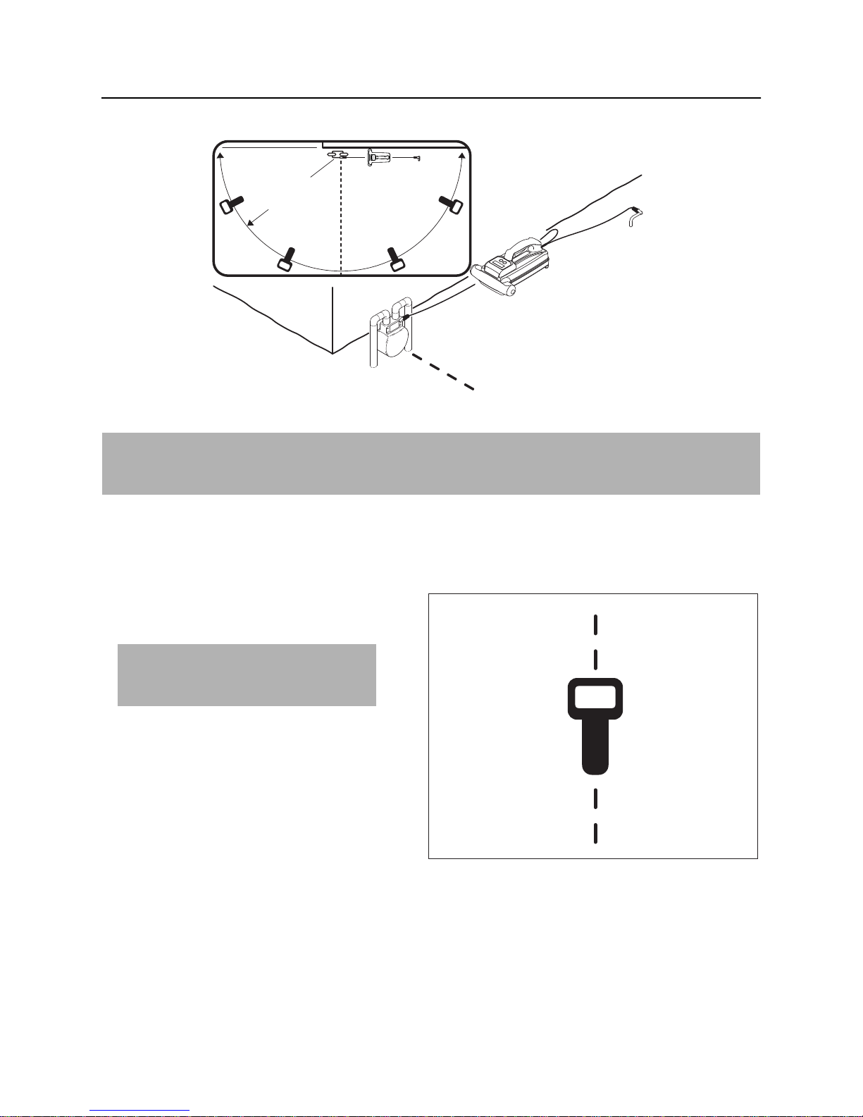
Induction (Broadcast)
To set up transmitter for induction (broadcast):
1. Remove leads and clamp from transmitter.
2. Place transmitter with the handle parallel
to suspected cable as shown.
Note: Transmitter handle must be
parallel to cable, as shown, in order to
produce the best signal.
3. Turn on transmitter.
4. Check battery level.
5. Select power level.
e16om010t.eps
CMW
Locate - 30 830R/T Operator’s Manual
Active Location
Technique
7.5 m
25 ft
e16om011t.eps
IMPORTANT: Follow steps 1-3 for all types of active location. For reference, the illustration above
shows direct connection method. If using induction (broadcast), ensure that transmitter handle is in line
with and above suspected cable, as shown on previous page.
1. Walk in an arc approximately 25’ (7.5 m) around transmitter.
2. Hold the receiver so that the handle points toward the transmitter, as shown.
3. Identify location of cable by using left/right indicators and signal strength.
4. Slowly rotate the receiver to determine
which direction the cable runs.
IMPORTANT: Receiver indicates the
best signal when the handle lines up
with the target cable.
5. Trace the cable and note depth estimates
every few paces.
6. Retrace the cable and mark with
appropriate flags or paint.
ss1080a-d.eps
CMW

830R/T Operator’s Manual Locate - 31
Active Location
Mark the Cable
Sweep, focus, and trace all detected signals in the area. Mark cable paths with colored paint or flags. See
the chart below for standard color markings for cable locations.
Utility Color Marking Symbol
electric red -Egas/oil yellow -Gcommunications orange -TEL- or -TVwater blue -Wsewer green -S-
Special Situations
Situation What to try
Signal is lost. Walk in a circle to detect a tee or bend in the cable.
Signal varies from low to high and is
unstable.
You are near a power line and are
receiving interference.
Target cable has connections to other
cables.
Signal is transferring to other cables. • Use direct connection, if possible, or use inductive
Mark as a hand-dig area.
Sweep the area in 50 Hz or 60 Hz power mode. If receiver
gives a strong signal response, a power line is interfering
with transmitter signal.
Disconnect target cable from other cables or use direct
connect or induction clamp to focus signal on target cable.
clamp.
• Move the ground stake away from the target cable and
away from other buried cables.
• Apply signal at the point where the target cable is
farthest from the other cables.
• Use lowest power level on transmitter.
CMW

Locate - 32 830R/T Operator’s Manual
Passive Location
Passive Location
Setup
Follow setup procedures for the type of locating you will be doing. Always check receiver battery level at
startup.
NOTICE: Cables with no A/C current flowing through them are hard to detect and may be hazardous
because they may still have voltage potential. To locate, turn on an appliance to cause current to flow
and use active search methods.
Technique
Survey the Site
Make a visual check of the site for signs of buried cables such as:
• recent trenching
• buried cable markers
• overhead lines that run down pole and underground
• gas meters
• valve sights
• drains or manhole covers
Sweep the Site
Search the site by walking a grid pattern while
holding receiver close to the ground.
NOTICE: Keep receiver vertical.
CMW
ss1076a-d.eps

830R/T Operator’s Manual Locate - 33
Passive Location
Focus the Signal
Move receiver over detected signal and rotate to find best signal response. Best signal indicates cable
direction.
Trace the Cable
Walk along the suspected path while moving
the receiver from side to side across the area.
IMPORTANT: Keep receiver handle parallel
to the suspected cable path.
ss1080a-d.eps
Mark the Cable
Sweep, focus, and trace all detected signals in the area. Mark cable paths with colored paint or flags. See
the chart below for standard color markings for cable locations.
Utility Color Marking Symbol
electric red -Ecommunications orange -TEL- or -TV-
Special Situations
Situation What to try
Signal is lost. Walk in a circle to detect a tee or bend in the cable.
Signal varies from low to high and is
unstable.
Mark as a hand-dig area.
CMW

Locate - 34 830R/T Operator’s Manual
Passive Location
CMW

830R/T Operator’s Manual Locating Concepts - 35
Locating Concepts
Chapter Contents
Signal Type . . . . . . . . . . . . . . . . . . . . . . . . . . . . . . . 36
• Active . . . . . . . . . . . . . . . . . . . . . . . . . . . . . . . . . . . . . . . . . . . . . . . . . . 36
• Passive . . . . . . . . . . . . . . . . . . . . . . . . . . . . . . . . . . . . . . . . . . . . . . . . . 36
Recommended Settings . . . . . . . . . . . . . . . . . . . . 36
Mode . . . . . . . . . . . . . . . . . . . . . . . . . . . . . . . . . . . . 37
• Receiver . . . . . . . . . . . . . . . . . . . . . . . . . . . . . . . . . . . . . . . . . . . . . . . . 37
• Transmitter . . . . . . . . . . . . . . . . . . . . . . . . . . . . . . . . . . . . . . . . . . . . . . 38
Receiver Gain Level . . . . . . . . . . . . . . . . . . . . . . . . 39
Frequency . . . . . . . . . . . . . . . . . . . . . . . . . . . . . . . . 39
Common Signal Problems . . . . . . . . . . . . . . . . . . 40
• Distortions . . . . . . . . . . . . . . . . . . . . . . . . . . . . . . . . . . . . . . . . . . . . . . 40
• False Signals . . . . . . . . . . . . . . . . . . . . . . . . . . . . . . . . . . . . . . . . . . . . 40
CMW

Locating Concepts - 36 830R/T Operator’s Manual
Signal Type
Signal Type
The 830R can detect two types of signals:
• Active signals that are placed on a target cable with a transmitter.
• Passive signals that reside on the target cable.
Active
There are three ways to place active signals on a target cable with a transmitter:
• Direct connection (preferred method) requires a connection to be made directly onto target cable.
• Inductive requires placing an optional inductive clamp around target cable.
• Induction (broadcast) method uses a built-in antenna to broadcast a signal onto cables near the
transmitter.
Passive
Power cable signals can be detected passively without a transmitter if optional power mode is installed.
Recommended Settings
Choose transmitter power level according to how the signal will be placed on the cable.
Direct Connection Inductive Clamp Induction (Broadcast)
low power high power low power
CMW

830R/T Operator’s Manual Locating Concepts - 37
Mode
Mode
Receiver
The 830R receiver has two available modes.
Mode Description Notes
Left/Right Allows receiver to trace
cables that have had an
83.0775 kHz signal placed on
them by a transmitter.
si0009c-d.eps
Power Allows receiver to trace live
power cables.
In North America, available
frequencies are: 60, 120, and
180 Hz.
60
c00ic105t.eps
In other locations, available
frequencies are 50, 100, and
150 Hz.
IMPORTANT: Current must be
flowing through the cable.
Left/Right
• Signal display: 0-999
• Gain control: automatic
• Location display: distance-sensitive left/right arrows indicate direction to line, become shorter as
receiver nears the line, become a diamond when centered, and display a depth icon in the diamond
when the receiver is stable.
• Audio: low tone to left of line, high tone to right of line, and quiet when centered above the line.
Power
• Signal display: 0-99
• Gain control: manual. If signal strength is above 80, decrease gain. If it is below 20, increase gain.
• Location display: single peak
• Audio: variable pitch with signal strength. Stronger signals produce higher pitch audio output.
CMW

Locating Concepts - 38 830R/T Operator’s Manual
Mode
Transmitter
The 830T receiver has two operating modes and two troubleshooting indicators.
Operating Mode Description Notes
Induction (broadcast) Signal is broadcast onto
target line using antenna.
c00ic102t.eps
Direct Connect or Inductive
Clamp
Signal is placed on target line
through direct connect leads
or inductive clamps.
Indicates a closed circuit with
good current flowing in the
line.
c00ic103t.eps
Troubleshooting Indicators Description Notes
Inductive (broadcast) Indicates broadcast antenna
is out of regulation.
This can be caused by placing the
transmitter too near a large metal
object, very low battery level, or a
damaged antenna.
c00ic111t.eps
Direct Connect Indicates an open circuit.
c00ic104t.eps
CMW
Indicates little to no current is
flowing in target line.

830R/T Operator’s Manual Locating Concepts - 39
Receiver Gain Level
Receiver Gain Level
In left/right mode, the receiver uses automatic gain control and requires no user adjustment.
In optional power mode, the user adjusts the receiver gain setting.
Action Result Effect
increasing gain more sensitive to signal allows location farther away from
signal source
decreasing gain less sensitive to signal stabilizes signal
Frequency
The 830R/T system operates at a single active frequency: 83.0775 kHz.
Advantages/Disadvantages
• Excellent performance on ungrounded or poorly grounded cables.
• Couples onto cables easily for good broadcast performance.
• Couples onto cables other than the target cable easily.
CMW

Locating Concepts - 40 830R/T Operator’s Manual
Common Signal Problems
Common Signal Problems
IMPORTANT: If target depth and location are critical, confirm by hand-digging or vacuum excavation.
Distortion
Distortion often happens when a metallic object partially distorts the signal, or a signal from a parallel cable
interferes with target signal.
False Signals
False signals describe situations where the receiver indicates a cable location where there is no cable.
False signals often happen when a cable tees or bends, or another cable runs parallel to or crosses the
target cable.
Tees, Bends, and Dead Ends
To find signal in these situations, enable peak verify feature and sweep in a circle as shown.
e16om017t.eps e16om018t.eps
CMW

830R/T Operator’s Manual Locating Concepts - 41
Common Signal Problems
Parallel Cables (Diverging Arrows in Left/Right Mode)
A B C
e16om019t.eps
In situations where another cable (C) runs parallel to the target cable (A), the high frequency signal will
couple to the other cable. This will allow the user to locate both cables in left/right mode and will create a
false cable (B) between them. When locating the false cable, note that the arrows will not indicate the
correct direction to the false cable. The false cable is simply the point where the left/right arrows switch
direction while pointing to the other two cables.
Peak Verify Feature
When using left/right mode in areas where there are multiple lines near the general area of the target line,
the peak verify feature can help identify the target line.
1. Center the receiver over the line using left/right arrows.
2. Press and hold Down Arrow key and sweep the area.
• Signal strength non-target lines will be much lower (A) compared to the response when using left/
right only (B).
• Signal strength on false locates will drop to or near zero.
CMW

Locating Concepts - 42 830R/T Operator’s Manual
Common Signal Problems
CMW

830R/T Operator’s Manual Service - 43
Service
Chapter Contents
General Care . . . . . . . . . . . . . . . . . . . . . . . . . . . . . . 44
As Needed . . . . . . . . . . . . . . . . . . . . . . . . . . . . . . . 44
CMW

Service - 44 830R/T Operator’s Manual
General Care
General Care
Under normal operating conditions, receiver and transmitter need only minor maintenance. Following
these care instructions can ensure longer equipment life:
• Do not drop the equipment.
• Do not expose the equipment to high heat (such as in the rear window of a vehicle).
• Clean equipment with a damp cloth and mild soap. Never use scouring powder.
• Do not immerse in any liquid.
• Inspect housing daily for cracks or other damage. If housing is damaged, contact your equipment
dealer for replacement.
• Do not mix new and used batteries.
As Needed
Location Task Notes
Receiver Unit Change batteries 2 “D” alkaline
Transmitter Unit Change batteries 6 “D” alkaline
Receiver Unit
Change Batteries
Use two D-cell alkaline batteries in receiver.
1. Turn quarter turn fastener to open battery
cover.
2. Remove batteries.
3. Insert batteries as shown.
4. Close battery door and tighten quarter turn
fastener.
5. Check operation. The unit will not come on
if a battery is installed backwards.
e16om012t.eps
CMW

830R/T Operator’s Manual Service - 45
As Needed
Transmitter Unit
Change Batteries
Use six D-cell alkaline batteries in transmitter.
1. Turn quarter turn fastener to open battery
cover.
2. Remove batteries.
3. Insert batteries as shown.
4. Close battery door and tighten quarter turn
fastener.
5. Check operation.
• A battery error message will be
displayed and unit will shut down if a
battery is installed backwards.
• Unit will not come on if all batteries are
installed backwards.
e16om013t.eps
CMW

Service - 46 830R/T Operator’s Manual
As Needed
CMW

830R/T Operator’s Manual Specifications - 47
830R Receiver
Specifications
830R Receiver
L
W
H
e16om006t.eps
Dimensions U.S. Metric
H Height 30.8” 78.1 cm
L Length 12.1 ” 30.7 cm
W Width 8.4” 21.3 cm
Operating weight 5.1 lb 2.3 kg
Performance
Active frequency: 83.0775 kHz
Passive frequencies: 60/120/180 (North America), 50/100/150 (other locations)
Gain: auto, manual in power frequencies
Depth accuracy * : +/- 5% to 10’ (3 m)
Batteries
Type: 2 D-cell alkaline
Life (continuous use at 70°F/21°C): 75 hours
Battery saver: unit shuts off after 30 minutes of inactivity
CMW

Specifications - 48 830R/T Operator’s Manual
830R Receiver
Environmental U.S. Metric
IP rating: IP65
Operating temperature range -4°F to 122°F -20°C to 50°C
Regulatory Compliance
FCC, IC, CE
Features
Graphical LCD with white LED backlight
Distance sensitive left/right indication
Dual tone left/right audio
Peak Verify
Auto depth reading
* Locators are calibrated to these tolerances under ideal test conditions. Actual operating conditions may
have signal distortions or noise sources which result in depth estimate errors.
CMW

830R/T Operator’s Manual Specifications - 49
830T Transmitter
830T Transmitter
L
W
H
e16om007t.eps
Dimensions U.S. Metric
H Height 5.6” 14.2 cm
L Length 11.1” 28.2 cm
W Width 8.5” 21.6 cm
Operating weight 4.6 lb 201 kg
Performance
Output frequency: 83.0775 kHz
Maximum power output: 1 watt
Output power settings: 3
Batteries
Type: 6 D-cell alkaline
Life (continuous use at 70°F/21°C): 150 hours
Battery saver: unit shuts off after 2 hours of inactivity
Environmental U.S. Metric
IP rating: IP65
Operating temperature range -4°F to 122°F -20°C to 50°C
Regulatory Compliance
FCC, IC, CE
Features
Graphical LCD with white LED backlight
CMW

Specifications - 50 830R/T Operator’s Manual
830T Transmitter
CMW

830R/T Operator’s Manual Support - 51
Procedure
Support
Procedure
Notify your dealer immediately of any malfunction or failure of Ditch Witch equipment.
Always give model, serial number, and approximate date of your equipment purchase. This information
should be recorded and placed on file by the owner at the time of purchase.
Return damaged unit to dealer for inspection and warranty consideration if in warranty time frame.
All repairs must be done by an authorized Ditch Witch Electronics repair facility. Repairs done elsewhere
will void warranty.
Resources
Publications
Contact your Ditch Witch dealer for publications and videos covering safety, operation, service, and repair
of your equipment.
Training
For information about on-site, individualized training, contact your Ditch Witch dealer.
CMW

Warranty - 52 830R/T Operator’s Manual
Limited Product Warranty Policy
Warranty
Limited Product Warranty Policy
Warranty Periods
New Product
A twelve-month period starts on the date of delivery to the end user:
trackers, remote displays, receivers, transmitters, radars, fault finders
A six-month period starts on the date of delivery to the end user:
directional and locate beacons
A three-month period starts on the date of delivery to the end user:
accessories: cables, clamps, canoes, bags, and adapters
Used Product (Cosmetics)
A three-month warranty starts on the date of delivery to the end user on used and refurbished products
sold from Ditch Witch Electronics dealers. Used products are non-returnable.
Service and Repair
A one-month warranty on labor starts on the date the unit is repaired, and a three-month warranty on parts
starts on the date the unit is repaired for all products.
Extended Warranty
The extended warranty may be purchased at the time the equipment is sold or anytime within the original
warranty period. The extension is for an additional twelve or twenty-four months, for a total coverage of
twenty-four to thirty-six months. Exclusions: All beacons and accessories.
CMW

830R/T Operator’s Manual Warranty - 53
Limited Product Warranty Policy
Details and Exclusions
• The warranty includes only Ditch Witch Electronics products and accessories that are manufactured
and distributed by Ditch Witch Electronics. The warranty compensates on defects in material or
workmanship.
• Defects will be determined through inspection by Ditch Witch Electronics or authorized repair centers.
Original purchaser must make the defective item available for inspection within 30 days of the date the
part fails.
• The warranty is limited to replacement of the defective part. The replacement part may be new or
remanufactured. Repair and installation of defective part will be at no charge when product or item is
delivered to Ditch Witch Electronics or an authorized repair center. The product or item will be returned
at no charge for return freight.
• The warranty periods do not represent the useful life of Ditch Witch Electronics products and
accessories.
• If Ditch Witch Electronics products are purchased for commercial purposes, as defined by the
Commercial Code, no warranties extend beyond the specific terms set forth in this limited warranty. All
other provisions of this limited warranty apply, including the duties imposed.
• Ditch Witch Electronics products have been tested to deliver acceptable performance in most
conditions.
• This limited warranty applies to the original purchaser only. Some states or jurisdictions do not allow
exclusion or limitation of incidental or consequential damages, so above limitation may not apply. This
limited warranty gives original purchaser specific rights that vary from state to state or jurisdiction to
jurisdiction.
• Each serial-numbered piece of equipment must be registered by the selling dealer to determine
warranty start date.
• When a registration is not received, the Ditch Witch Electronics shipping date is used to establish the
warranty period start date.
• Product inspection and estimates may require that the unit be disassembled and tested.
• Out-of-warranty inspection costs include labor accrued at the full labor rate plus return freight.
• Approved out-of-warranty repair costs include parts, labor accrued at full labor rate, plus return freight.
Revision F, September 2006
CMW

Warranty - 54 830R/T Operator’s Manual
Limited Product Warranty Policy
CMW
 Loading...