

Page 1

Operation and Maintenance
Instructions Manual
DDFP SERIES ENGINES
FOR
FIRE PUMP APPLICATIONS
Printed in U.S.A.
This manual covers Detroit Diesel engines
modified by Clarke DD-A
for fire pump service
LISTED APPROVED LISTED
FM
C13194
MP-4 7/96
Page 2

ABBREVIATIONS
AC Alternating Current
AEC Automatic Engine Controller
API American Petroleum Institute
CCW Counter-clockwise engine rotating (front view)
CDD-A Clarke Detroit Diesel-Allison
CW Clockwise engine rotation (front view)
DC Direct Current
DDC Detroit Diesel Corporation
DDFP Detroit Diesel Engines approved for Fire Pump Service
as certified by FM/UL/ULC for Clarke Detroit Diesel-Allison
FM Factory Mutual Research
GM General Motors Corporation
ID Identification
IP Instrument Panel
I-53 In-Line Cylinder arrangement 53 Series DDC Engine
I-71 In-Line Cylinder arrangement 71 Series DDC Engine
NA Naturally Aspirated
NC Normally Closed
NO Normally Open
NFPA National Fire Protection Association
P/N Part Number
PSI Pounds Per Square Inch
PTO Power Take Off
RPM Revelutions Per Minute
SAE Society of Automotive Engineers
S/N Serial Number
TTurbocharged
TA Turbocharged and Aftercooled
UL Underwriters Laboratories Inc.
ULC Underwriters Laboratories of Canada
V-92 Vee cylinder arrangement 92 Series DDC engines
V-71 Vee cylinder arrangement 71 Series DDC engines
LISTED APPROVED LISTED
FM
Page 3

TABLE OF CONTENTS
SUBJECT PAG E
ABBREVIATIONS........................................................................................................................................ Inside Front Cover
DESCRIPTION — Section 1
Principles of Operation .................................................................................................................................................... 1
General Description .......................................................................................................................................................... 2
Model and Serial Number Designation ............................................................................................................................ 3
Engine Equipment ............................................................................................................................................................ 4
FM/UL Nameplate ............................................................................................................................................................ 5
General Specifications ...................................................................................................................................................... 6
OPERATING INSTRUCTIONS — Section 2
Engine Start-Up and Operating Instructions .................................................................................................................... 8
Standard Model Views .................................................................................................................................................... 9
Electronic Speed Switch .................................................................................................................................................. 10
Preventative Maintenance Schedule.................................................................................................................................. 11
ENGINE SYSTEMS — Section 3
Fuel System — Section 3.1 .............................................................................................................................................. 12
Operation.................................................................................................................................................................... 12
Maintenance & Service Procedures .......................................................................................................................... 15
Fuel System Schematic.............................................................................................................................................. 14
Air Intake and Exhaust System — Section 3.2 ................................................................................................................ 16
Air System Operation ................................................................................................................................................ 16
Maintenance & Service Procedures .......................................................................................................................... 19
Exhaust Operation...................................................................................................................................................... 19
Lubrication System — Section 3.3 .................................................................................................................................. 20
Operation.................................................................................................................................................................... 20
Lubricating System Schematics ................................................................................................................................ 21
Maintenance & Service Procedures .......................................................................................................................... 22
Cooling System — Section 3.4 ........................................................................................................................................ 25
Operation.................................................................................................................................................................... 25
Maintenance & Service Procedures .......................................................................................................................... 30
Electrical System — Section 3.5 ...................................................................................................................................... 31
Operation.................................................................................................................................................................... 31
Maintenance & Service Procedures .......................................................................................................................... 35
DC Wiring Diagram.............................................................................................................................................. 37, 38
Engine Heater AC Wiring Diagram .......................................................................................................................... 39
Falk Drive Coupling Instructions — Section 3.6 ............................................................................................................ 40
Installation Procedures .............................................................................................................................................. 41
ENGINE TUNE-UP — Section 4
Tune Up ............................................................................................................................................................................ 46
TECHNICAL DATA — Section 5 .......................................................................................................................................... 47
PA RTS INFORMATION — Section 6
Basic Engine Parts ............................................................................................................................................................ 48
Standard Option Parts ...................................................................................................................................................... 49
OWNER ASSISTANCE — Section 7 ............................................................................................................................ 50, 51
WARRANTY — Section 8 ................................................................................................................................................ 52, 53
STORAGE — Section 9 .......................................................................................................................................................... 54
ALPHABETICAL INDEX — Section 10 .......................................................................................................................... 55, 56
Page 4
SECTION 1 DDFP
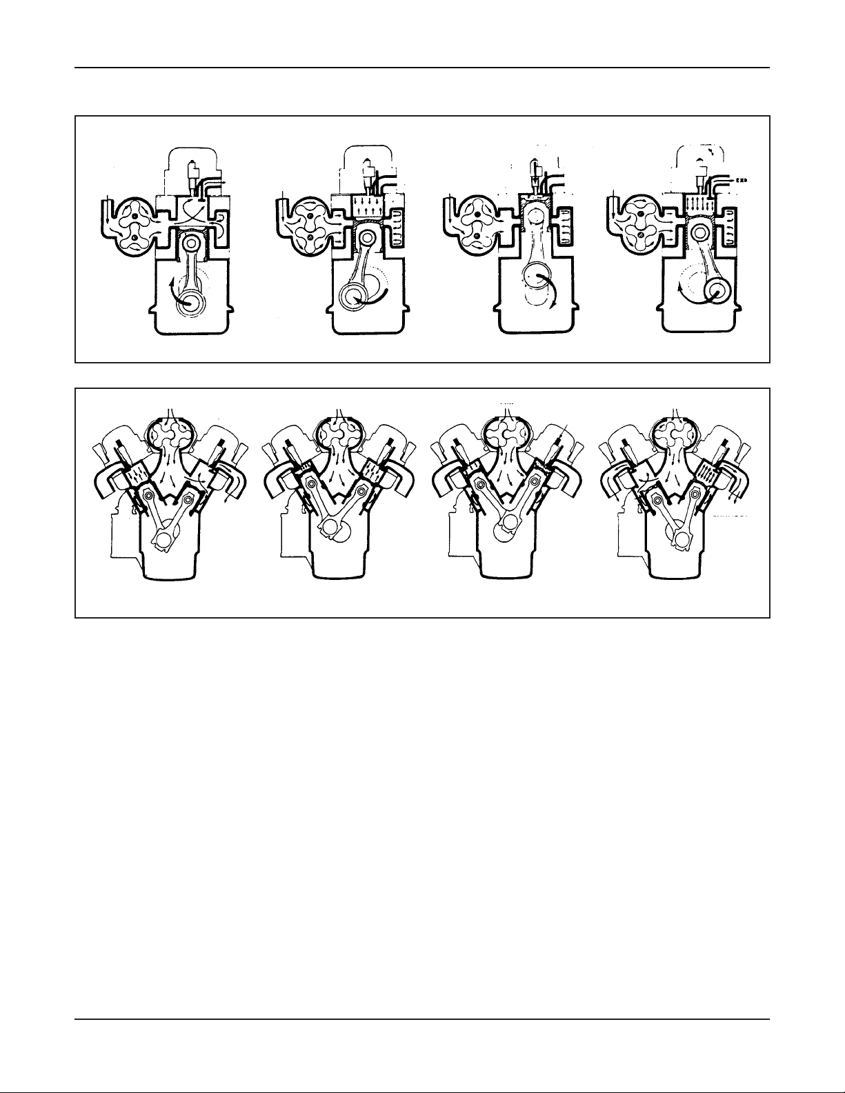
PRINCIPLES OF OPERATION
FUEL
AIR
AIR
AIR
AIR
AIR
AIR
Fig. 1 - In-Line Cylinder Arrangement
AIR
AIR
FUEL
AIR
ExhaustPowerCompressionScavenging
AIR
11826
EXHAUST
SCAVENGING EXHAUSTPOWERCOMPRESSION
Fig. 2 - Vee Block Cylinder Arrangement
The diesel engine is an internal comb ustion power unit, in
which the heat of fuel is converted into work in the cylinder
of the engine.
In the diesel engine, air alone is compressed in the cylinder;
then, after the air has been compressed, a charge of fuel is
sprayed into the c ylinder and ignition is accomplished by
the heat of compression.
The Two-Cycle Principle
In the tw o-cycle engine, intake and e xhaust functions tak e
place during part of the compression and po wer strokes respectively (Fig. 1) or (Fig. 2). In contrast, a four -cycle
engine requires four piston strokes to complete an operating
cycle; thus, during one half of its operation, the four-cycle
engine functions merely as an air pump.
A blo wer is pro vided to force air into the c ylinders for
expelling the exhaust gases and to supply the cylinders with
fresh air for combustion. The cylinder wall contains a row of
ports which are above the piston when it is at the bottom of
its stroke. These ports admit the air from the blower into the
cylinder as soon as the rim of the piston unco vers the ports
(Fig. 1 & 2 - Scavenging).
12240
The unidirectional flow of air toward the exhaust valves produces a scavenging effect, leaving the cylinders full of clean
air when the piston again covers the inlet ports.
As the piston continues on the upw ard stroke, the exhaust
valves close and the charge of fresh air is subjected to compression (Fig. 1 & 2 - Compression).
Shortly before the piston reaches its highest position, the
required amount of fuel is sprayed into the comb ustion
chamber by the unit fuel injector (Fig. 1 & 2 - Po wer). The
intense heat generated during the high compression of the
air ignites the f ine fuel spray immediately. The combustion
continues until the fuel injected has been b urned.
The resulting pressure forces the piston do wnward on its
power stroke. The exhaust valves are again opened when the
piston is about half way down, allowing the burned gases to
escape into the e xhaust manifold (Fig. 1 & 2 - Exhaust).
Shortly thereafter , the do wnward mo ving piston unco vers
the inlet ports and the c ylinder is again swept with clean
scavenging air. This entire combustion cycle is completed in
each c ylinder for each re volution of the crankshaft, or, in
other words, in two strokes; hence, it is a "two-stroke cycle".
Page 1
Page 5

SECTION 1
DDFP
DESCRIPTION
Introduction
NFPA Pamphlet 20 sta tes "The compression ignition diesel
engine has proved to be the most de pendable of the inter nal
combustion engines for dri ving fire pumps." The diesel en gine will operate under emer gency power conditions w here
loss of utility or stand-b y electric po wer renders electric
motor driven pumps useless. The diesel driven fire pump system is preferred by most insurance companies.
This manual co vers Detroit Diesel engines. These engines
have been manuf actured with specif ic options to function
integrally with an automa tic engine controller for stand-by
fire protection service and to meet NFP A-20 requirements.
These systems ar e designed to function under emergenc y
conditions and to assist in holding fire damage to a minimum.
Complete understanding of the operation and maintenance of
this fire protection system is essential to ac hieve this objec tive.
A separate manual co vers the operation and maintenance of
the Automatic Engine Controller (AEC).
The two-cycle engines co vered in this man ual are produced
with v arious c ylinder arrangements. The same bore and
stroke and many of the major working parts such as injectors,
pistons, connecting rods, cylinder liners and other par ts are
interchangeable within eac h engine series. The engines are
either naturally aspirated (NA) or turbocharged (T) and some
units are turbocharged and aftercooled (TA).
The engines ha ve either an in-line or a vee type c ylinder
arrangements. The engine may ha ve clockwise (CW) or
counter-clockwise (CCW) r otation. Rotational reference is
made from a front vie w of the engine to deter mine the r otation of the output shaft. All other engine references, (
left side) are made from a rear view of the engine, looking at
the flywheel.
All DDFP engines are Underwriters Laboratories (UL) listed,
Underwriters Laboratories of Canada (ULC) listed and/or
Factory Mutual (FM) approved and meet the requirements of
the National Fire Protection Association (NFPA) standard 20.
right or
to the oil cooler. From the oil cooler the oil enter s a longitudinal oil g allery in the c ylinder b lock where the suppl y
divides and is channeled to the turbocharger (if included), to
the cam and balance shaft end bear ings and c ylinder head,
with the remainder going to the main bear ings and connecting rod bearings via the drilled crankshaft. The oil then drains
back into the oil pan.
Coolant is circulated through the engine by a centrifugal-type
water pump. Heat is removed from the coolant as it circulates
in a closed system through the heat exchanger. Control of the
engine temper ature is accomplished b y a thermostat which
regulates the f low of the coolant within the cooling system.
Raw water from the f ire pump passes thr ough a tube b undle
in the heat e xchanger to remo ve the heat from the engine
coolant.
Fuel is dra wn from the suppl y tank through a str ainer by a
gear-type fuel pump. It is then forced through a filter and into
the fuel inlet gallery in the cylinder head and to the injectors.
Excess fuel is r eturned to the suppl y tank through the fuel
outlet g allery and connecting lines. Since the fuel is con stantly circulating through the injector s, it serves to cool the
injectors and purges the system of air.
Air for sca venging and combustion is supplied b y a blo wer
which pumps air into the engine cylinders via the air box and
cylinder liner por ts. All air enter ing the blo wer first passes
through an air c leaner. Turbocharges, when included, are
located between the air cleaner and the blower. Some engines
also include an after cooler which cools the air prior to entering the cylinders.
Engine starting is usually provided by an electric starting system. The electric starting motor is energized by a storage battery. A battery-char ging alter nator, with a b uilt-in v oltage
regulator, serves to keep the battery charged while the unit is
running. At rest, a battery charger in the AEC keeps batteries
charged.
Engine speed is regulated by a mechanical type eng ine governor with a tamper proof speed control device.
Each engine is equipped with an oil cooler, lubricating oil filter, fuel f ilters, air cleaner, heat e xchanger, starting motor ,
alternator, instrument panel and engine jacket water heater.
Full lubrication oil pressure is supplied to all main, connecting rod and camshaft bear ings, and to other mo ving parts
within the eng ine. A gear type pump dr aws oil fr om the oil
pan through an intak e screen, through the oil f ilter and then
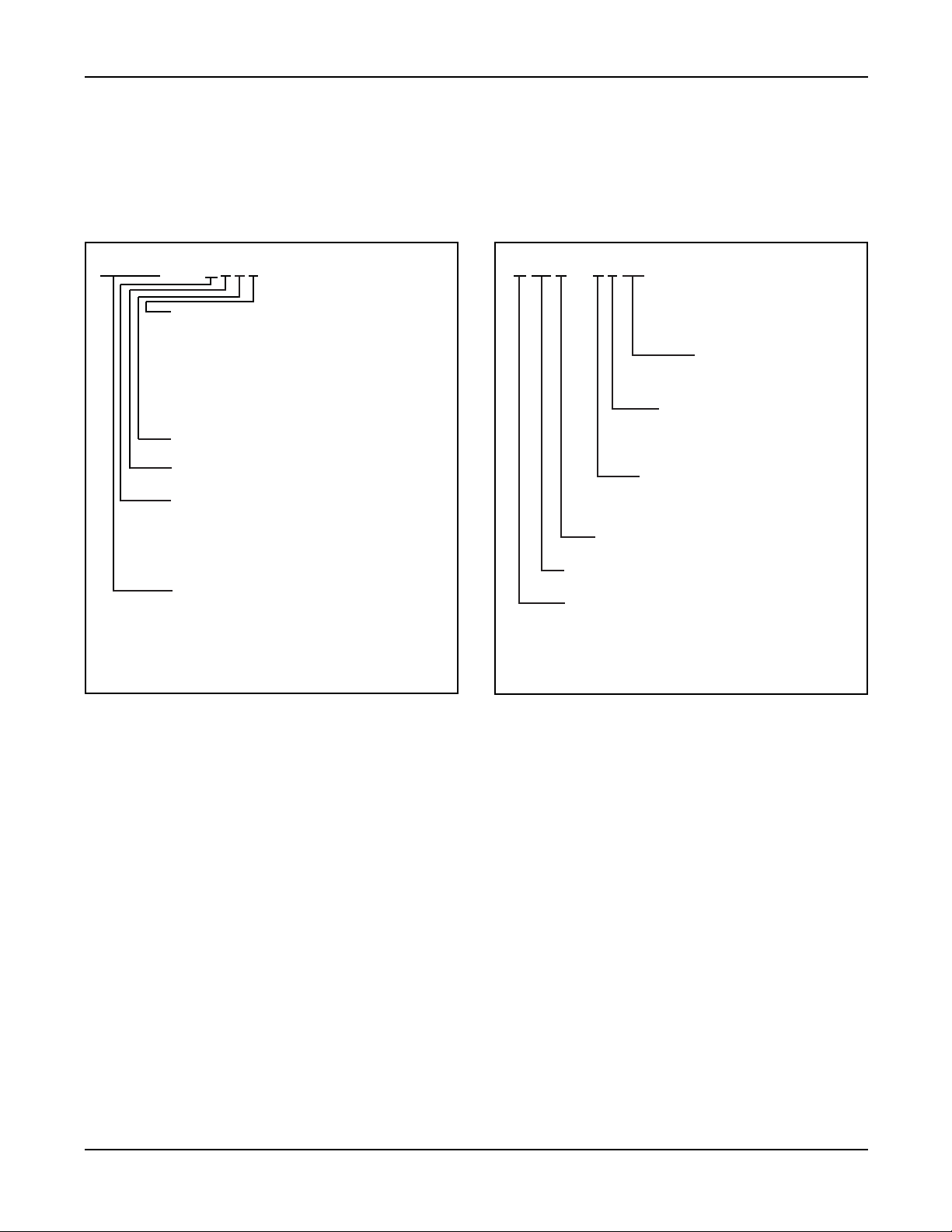
Model Numbering & Identification
Two model numbers are sho wn on this pr oduct. First is the
Clarke FM/UL/ULC a pproved model n umber sho wing the
prefix DDFP. Figure 3 e xplains the identification system on
DDFP units. Second is the DDC basic engine model number
using eight digits. Figure 4 provides details for understanding
the significance of each digit.
Page 2
Page 6
SECTION 1 DDFP
The DDFP model n umber appears on the FM/UL/ULC ta g
attached to the right rear of the engine flywheel housing. The
DDC basic engine model number appears on the engine rocker cover. The engine S/N should be the same a t both locations.
D D F P — L 6 V T
N Naturally Aspirated
TTurbocharged
ATurbocharged & Aftercooled
H High Output
A 71 Series DDC Engine, In-Line
D 53 Series DDC Engine
F 92 Series DDC Engine
V 71 Series DDC Engine, Vee
(X) Number of Cylinders
O Basic Build Level
L Reduced Output Build
T Alternate Turbo
I Included With Number of Cylinders
on
Engines With 10 or more Cylinders
Detroit Diesel Engines
Modified by Clarke and
Certified by FM/UL/ULC for
Fire Pump Service
Figure 3 - Clarke FM/UL/ULC Model
On some engines, you may find different engine rated horsepower and oper ating RPM on the r ocker co ver name pla te
than on the FM/UL/ULC ta g attached to the f lywheel housing. The FM/UL/ULC tag is the official power data and takes
presi-dence over the rocker cover data.
8 0 6 4 — 7 4 1 2
Specific Engine For
Fire Pump Application
0 NA Engine
3Turbocharged
4Turbo & Aftercooled
6Turbo & Aftercooled
3 LH Rotation
7 RH Rotation
8 RH Rotation
Industrial Power Unit
XX Number of Cylinders
1 71 Series DDC Engine, In-Line
5 53 Series DDC Engine
7 71 Series DDC Engine, Vee
8 92 Series DDC Engine
Figure 4 - DDC Basic Engine Model
(See Page 1)
Page 3
Page 7

DDFP STANDARD ENGINE EQUIPMENT LIST
DDFPSECTION 1
—Air cleaner, oiled gauze or dry type for protected environment.
—Battery charging alternator (12 or 24V-DC) negative
ground
—Engine coolant heater with AC power connection (120,
208 or 240V)
—Engine oil cooler
—Electric starting motor (12 or 24V-DC)
—Exhaust manifold insulation or heat shield
—Fuel inlet check valve
—Fuel filters - Primary and Secondary
—Junction box (DC control) for connection to engine
controller
—Low oil pressure switch
—Manual over-ride of automatic operations including
instruction plate
—Manual start contactors - two provided on each engine
—Oil filter(s) full flow with by-pass
—Oil pan heater (optional)
—Overspeed control and reset switch
—Solenoid Run/Stop control-signal from AEC
—Governor speed control
(10% No Load to Full Load)
—Heat Exchanger with pressure cap
—High water temperature switch
—Instrument panel with water temperature, oil pressure
and voltmeter
—Direct mounted engine half of Falk coupling
—Tachometer with hour meter
—Tamper proof throttle control factory preset
—Wiring harness for DC control
Page 4
Page 8
SECTION 1 DDFP
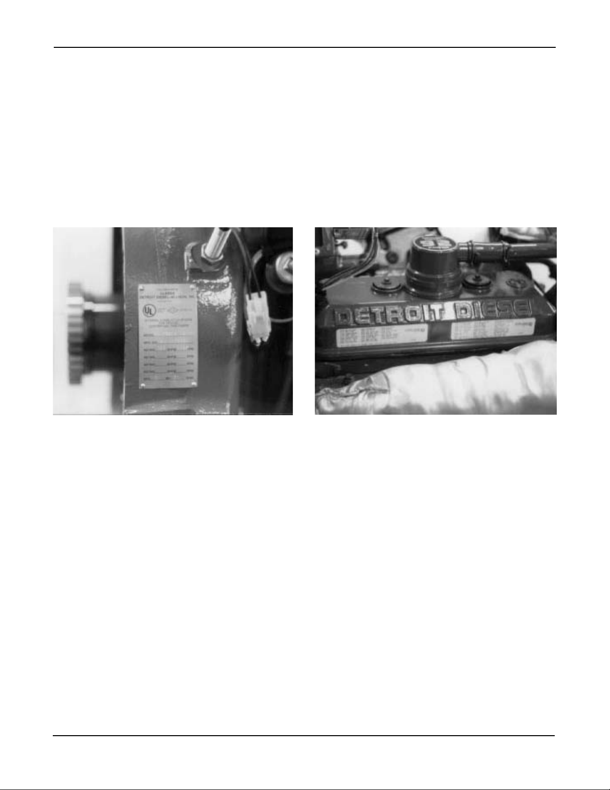
FM/UL/ULC CERTIFICATION NAME PLATE
The standard nameplate (Fig. 5) contains the follo wing information: FM/UL certified model number; Clark e specification number; production date; rated horsepower; full load
engine speed; basic engine serial number (S/N). The name
plate is located on the right rear of the engine and attached
to the flywheel housing.
The DDC model and S/N are found on the manuf acturer's
I.D. label (Fig. 6) on the v alve rocker cover. This model is
also stamped on the engine block.
On the Inline engines, the model number is stamped into the
cylinder block casting on a machined pad abo ve and to the
right of the engine blower. On the VEE engines, the number
is stamped at the right front of the block just behind the
water pump.
When requested, a ULC nameplate is provided in addition to
the FM & UL nameplate. This plate is mounted separately
on the engine.
Figure 5 Figure 6
Page 5
Page 9

SECTION 1
Type
General Specifications - DDFP Models
03DN
03DT
L3DT
T3DT
2 Cycle
2 Cycle
04AN
04AT
2 Cycle
DDFP
L6VT
T6VT03AN
2 Cycle
Number of Cylinders
Bore (inches)
Bore (mm)
Stroke (inches)
Stroke (mm)
Compression Ration (T Eng)
Compression Ration (N Eng)
Total Displacement (cub. in.)
Total Displacement (liters)
Number of Main Bearings
3
3.875
98
4.5
114
18.7:1
21.0:1
159
2.61
4
General Specifications - DDFP Models
06FA
06FH
3
4.25
108
5
127
– –
18.7:1
213
3.49
4
L8FA
08FA
4
4.25
108
5
127
17:1
18.7:1
284
4.66
5
08FH
12FT
6
4.25
108
5
127
17:1
– –
426
6.99
4
12FH
Type
Number of Cylinders
Bore (inches)
Bore (mm)
Stroke (inches)
Stroke (mm)
Compression Ratio
Total Displacement (cubic inches)
Total Displacement (liters)
Number of Main Bearings
For Specific Operational Data For Each Engine Model, Refer To Technical Data Section 5.
2 Cycle
6
4.84
123
5
127
17:1
552
9.05
4
2 Cycle
6
4.84
123
5
127
15:1
552
9.1
4
2 Cycle
8
4.84
123
5
127
17:1
736
12.07
5
2 Cycle
8
4.84
123
5
127
15:1
736
12.07
5
2 Cycle
12
4.84
123
5
127
17:1
1104
18.1
8
2 Cycle
12
4.84
123
5
127
15:1
1104
18.1
8
Page 6
Page 10
SECTION 1 DDFP
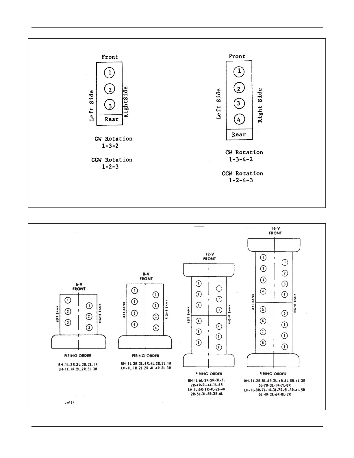
3 - IN-LINE 4 - IN-LINE
Fig. 7 - Cylinder Designation and Firing Order
Fig. 8 VEE Engine Cylinder Designation and Firing Order
Page 7
Page 11

ENGINE START UP AND OPERATING INSTRUCTIONS
DDFPSECTION 2
Preparing New Engine For Start-Up
Before starting a new or overhauled engine for the first time,
carefully read and follow the check list below. Attempting to
run the engine before studying these instructions may result
in serious damage to the engine.
1. Make all electrical (DC) connections between engine
(DC) junction box and engine controller.
2. Make all raw water connections to heat exchanger tank.
Discharge line should be one size larger than supply line and
rise a minimum of 3 inches abo ve heat e xchange outlet to
assure complete co verage of the heat e xchange core. Discharge water is to be piped to an open w aste cone.
NOTE: Do not allo w raw w ater plumbing to stress on
engine heat exchanger.
3. Install all of the drain cocks or plugs in the cooling sys-
tem (drain cocks are removed for shipping engines dry).
4. Fill engine cooling system with PRE-MIXED 50 per -
cent water and 50 percent permanent type antifreeze solution. Fill to top heat exchanger tank.
NOTE: Refer to Section 3.4 for Cooling System
Fill Procedure.
9. Unbox and inspect air cleaner element for damage or de-
terioration. Install air cleaner element on engine.
10. Install batteries, battery cables and service batteries as
required by manufacturer. See battery recommendation under
Section 3.
11. Install exhaust system. A vertical exhaust outlet is furnished for customer/contractor installation. A fle xible e xhaust connector must be installed at outlet.
NOTE: Do not exceed exhaust back pressure limits. See
Section 5 for details for each engine model.
NOTE: Do not allow exhaust system plumbing to stress
on engine.
If any problems or questions develop in performing the above
procedures, advise the authorized DDC Distributor/Dealer of
details when making arrangements for the installation inspection.
NOTE: Only one initial start-up inspection is provided at
no charge for an installation re view. Be sure to
cover items 1-11 thoroughly before calling the
authorized DDC Distributor/Dealer.
Normal Running
5. Connect fuel supply line and fuel return line to supply
tank. Bleed fuel system of all air.
NOTE: Do not use galvanized material for any compo-
nent part of a diesel fuel system. The fuel will
chemically react with the zinc coating.
6. Fill fuel tank with No. 2 diesel fuel.
NOTE: No. 2 diesel fuel is the only recommended fuel,
engine po wer could be af fected by using an y
other type.
7. Fill engine crankcase with SAE 40 weight oil per oil
recommendations of Section 3. Oil filler locations vary by
engine model. Most will be found on the engine valve cover.
8. Pre-lubricate engine to a minimum 25 psi (172 KPA) to
insure an immediate flow of oil to all bearings at the initial
engine start-up. Contact the authorized DDC
Distributor/Dealer if you require assistance with this item.
Fire pump engines are run periodically to assure proper operation. Units may be run automatically as programmed within
the AEC or the y may be run manually for systems e valuation.
NOTE: For specific operating instructions, see Section 3
- Electrical System.
Normal Care And Maintenance Should Be Made On
The Following Systems:
Fuel System
Periodically check fuel tank to assure it is full. Keep the fuel
tank f illed to reduce condensation to a minimum and to
assure full running time during emergency operation. Engine
fuel filter should be changed annually or when fouled with
contamination. If contaminated, locate the source and correct. (See Section 3 page 13 for proper procedure). If the
engine runs out of fuel or if the engine is out of service for a
considerable length of time, it may be necessary to reprime
the fuel system. Refer to Section 3 for proper procedure.
Page 8
Page 12
SECTION 2 DDFP
Drive Belts
Adjust the alternator drive belts as recommended under the
Preventive Maintenance Section 2.
engine coolant between 120 -140 de grees F (49-60° C).
When running, engine coolant temperature should re gister
between 180-200 de grees F (82-93° C). See Section 3 for
detailed information.
Storage Battery
Check the batteries. The top should be clean and dry, the terminals tight and protected, and the electrolyte must be at the
proper level. They should be tested weekly to determine the
condition of cells, and the amount of charge.
NOTE: Once each week, check the batteries with a hy-
drometer; the corrected reading should be 1.265
or higher. Hydrometer readings should be corrected for the temperature of the electrolyte.
Should a problem be detected, locate source and
correct.
Oil Pressure
Normal engine operating oil pressure is 40-70 psi (276-433
kPa). If operating pressure falls below 30 psi (206 kPa), stop
engine and investigate cause.
Coolant Temperature
When unit is not running, Jacket w ater heaters maintain
Standard Model Views
Crankcase
The oil le vel should be maintained between the Full mark
and Low mark. Check the oil le vel weekly prior to normal
exercise. The oil dipstick is located on the right side of the
engine. Do not check oil level when the engine is running. If
the engine crankcase was refilled, stop the engine after normal operating temperature has been reached, allow the oil to
drain back into the crankcase (approximately 10 minutes)
and check the oil le vel. Add oil, if necessary, to bring it to
the proper level on the dipstick.
NOTE: DO NOT OVER-FILL CRANKCASE.
Use only the recommended lubricating oil specif ied under
Section 3 - Lubricating Oil.
Running Inspection
While the engine is running at operating temperature, check
for coolant, fuel or lubricating oil leaks. Tighten the line
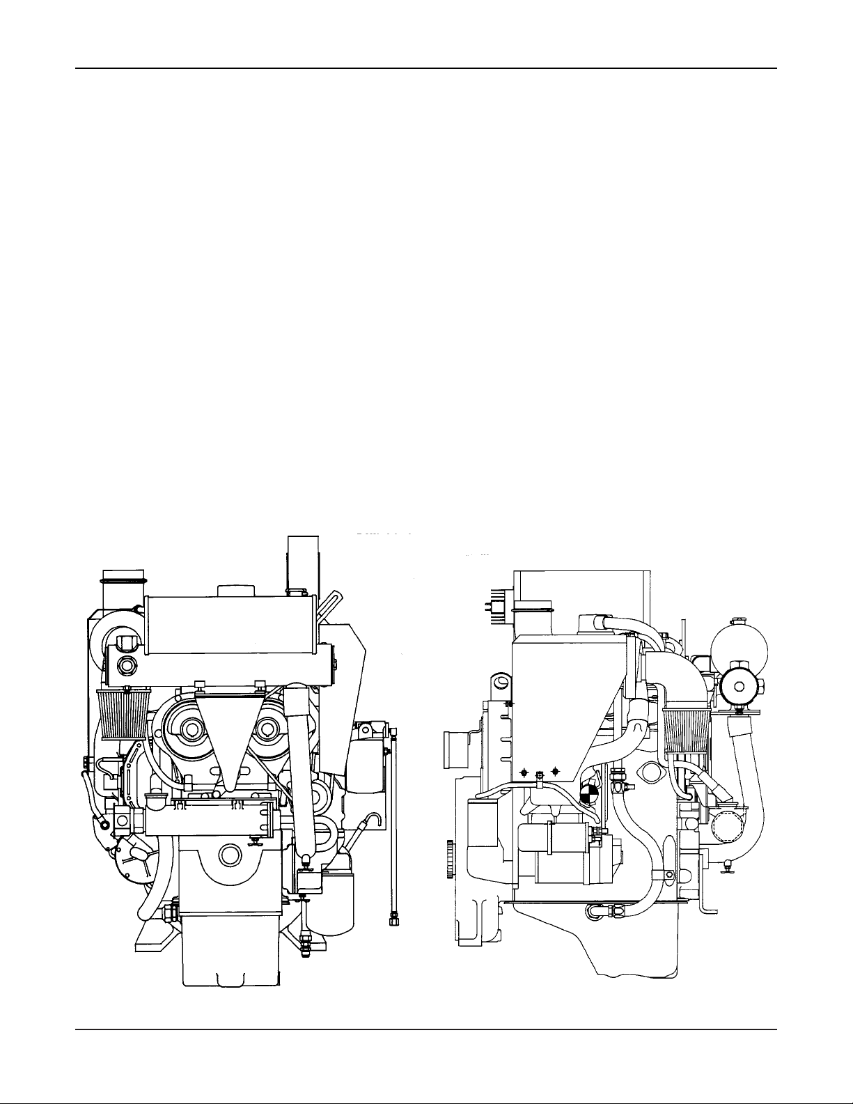
Right Side View (I-53)Front View (I-53)
Page 9
Page 13
DDFPSECTION 2
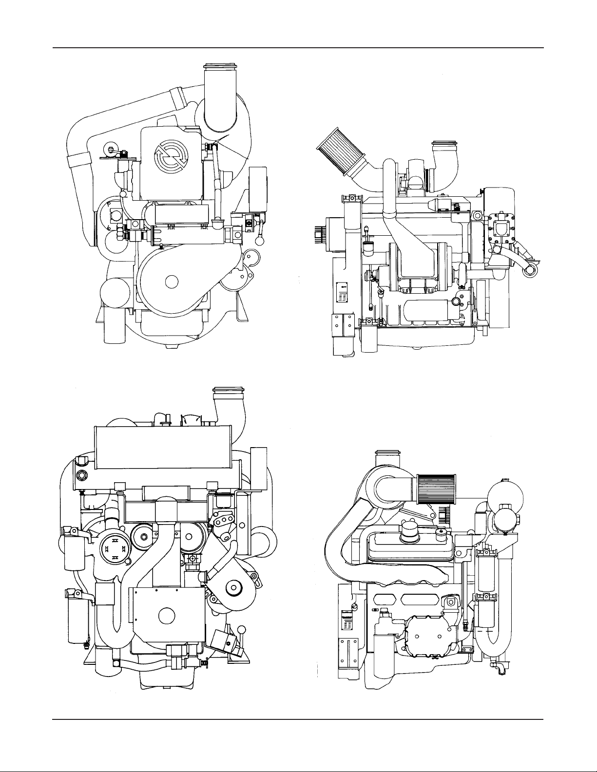
Front View (I-71)
Right Side View (I-71)
Front View (V-71)
Right Side View (6V-71)
Page 9-A
Page 14
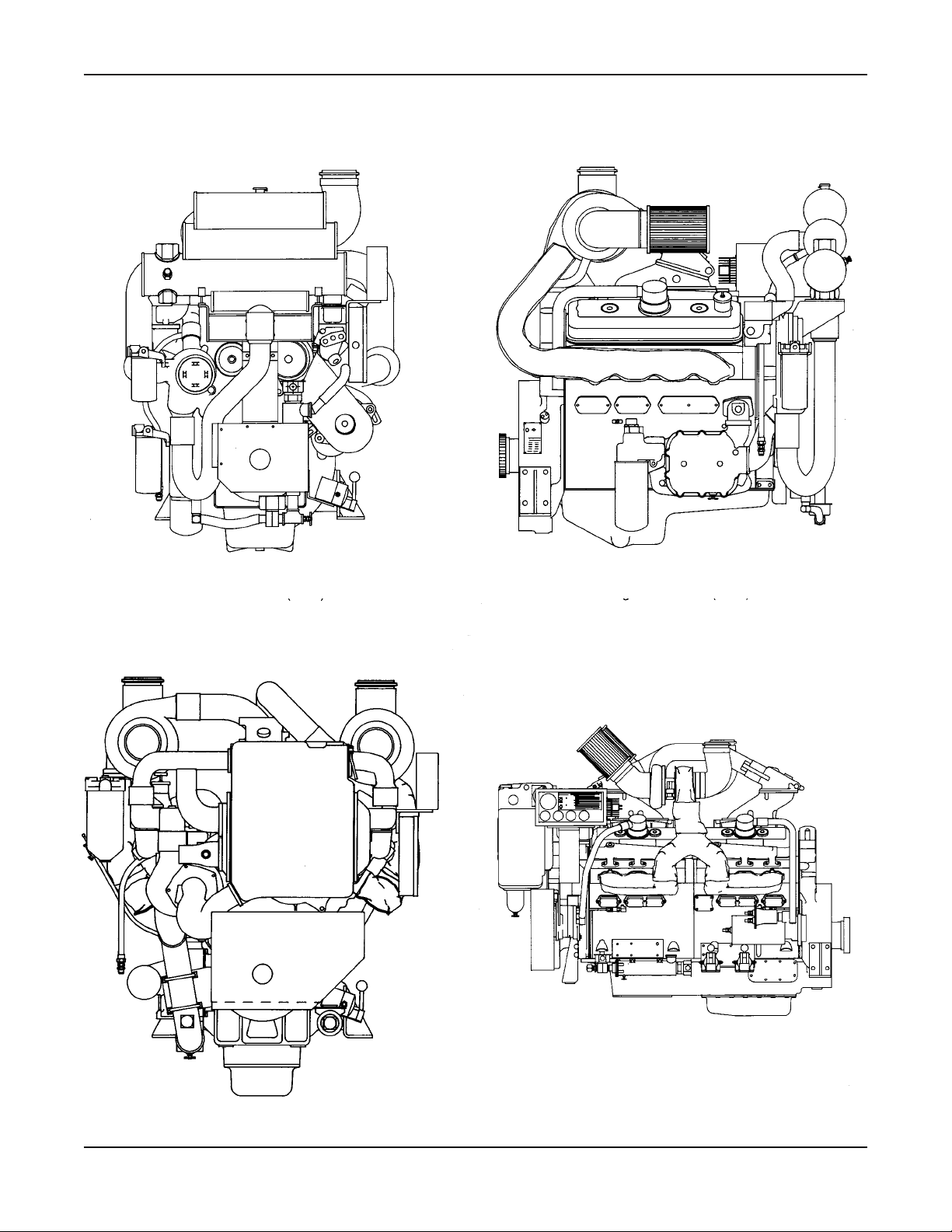
SECTION 2 DDFP
Front View (V-92) Right Side View (V-92)
Front View (12V-92) Left Side View (12V-92)
Page 9-B
Page 15

SECTION 2
DDFP
ELECTRONIC SPEED SWITCH
The speed switch is located on the rear or back side of the
instrument panel.
There are two (2) functions built into the speed switch. First
to terminate starter cranking, once the engine is running.
Second to signal the controller and ef fect an engine shutdown in the event of an engine overspeed condition.
Features of the speed switch are a "manual reset b utton" on
the face of the switch, which must be pushed into reset the
switch should the engine shutdo wn from an o verspeed condition. Additionally, a varification circuit to assist in checking or setting the overspeed set point.
CALIBRATION
Both crank terminate (SW#1) and o verspeed (SW#2) set
points, are set at the factory and should not require additional calibration. Adjustments can be made to the set points of
SW#1 and/or SW#2 if required using a je welers screw driver. Turning the corresponding adjustment scre w CW to
increase or CCW to decrease the set point. To access either
adjustment screw remove the small co ver plate on the f ace
of the speed switch.
OVERSPEED VARIFICATION
To varify the function of the overspeed signal (SW#2) without overspeeding the engine, install a jumper wire on terminals "C & D" of the speed switch. This will provide the controller with an o verspeed signal and engine shutdo wn at
67% of calibrated RPM.
Start the engine via the controller , the speed switch will
effect an overspeed signal and shutdown protecting both the
engine and pump.
EXAMPLE
Rated Speed : 2100 RPM
Overspeed Shutdown : 2520 RPM (120% of 2100 RPM)
Varification Shutdown : 1688 RPM (67% of 2520 RPM)
CAUTION
Crank terminate (SW#1) adjustment should be done reading
"engine crankshaft" speed at the front of the engine using a
hand held tachometer . For starter protection and optimum
engine stability , this switch should be calibrated to 1000
RPM.
Overspeed (SW#2) adjustment should be done r eading "engine crankshaft" speed at the front of the engine using a
hand held tachometer . This switch should be calibrated to
120% of rated speed, but ne ver higher than 3200 RPM.
Refer to the stainless steel nameplate located at the right rear
of the engine for the correct rated speed.
After v arification of SW#2 the jumper wir e must be
removed and the "reset b utton" pushed in to re-instate normal operation of the engine and speed switch.
Page 10
Page 16

SECTION 2 DDFP
PREVENTIVE MAINTENANCE SCHEDULE
Item
Weekly
1. Run Engine
(per NFPA 20 Specifications) X
2. General Inspection X
3. Lubricating Oil X R
4. Fuel Tank X
5. Fuel Lines X
6. Cooling System X R
7. Battery X C
8. Air Cleaner - Dry Type (-03AN & -04AN) X R R
- Oil Gauze (All Other Models) X C R
9. Drive Belts X
10. Speed Control X
11. Fuel & Lube Oil Filters R
12. Exhaust System X X
Inspection Interval
6 Months 1 Year 2 Year
13. Battery Charging Alternator X
14. Manual Contractors X
15. Operating Gauges X
16. Crankcase Vent System X
17. Heat Exchanger Electrode X
18. Governor Run-Stop Mechanism X
19. Jacket Water Heater X
20. Wiring System X
21. Coolant Hose Inspection X R
See Parts Information Section 6 for Lubricating Oil And Coolant Analysis' Kits
IMPORTANT: Set AEC to "of f" while servicing engine.
Before turning the AEC to the "off" position, check with the
maintenance and security supervisors to v erify that all departments concerned will be alerted of the temporary interruption of their f ire protection equipment for normal maintenance or testing. Also, alert the local fire department in the
event that the AEC is connected by silent alarm to headquarters. When servicing is complete,return AEC selector to
"Automatic" position and the manual operating le ver to
"auto - off" position.
X Check
R Replace
C Clean
Page 11
Page 17

SECTION 3
DDFP
ENGINE SYSTEMS
Section 3.1 Fuel System
Section 3.2 Air Intake & Exhaust System
Section 3.3 Lubrication System
Section 3.4 Cooling System
Section 3.5 Electrical System
Section 3.6 Falk Drive Coupling
In this Engine Systems section that follows, data is presented in a generalized way for a description of system operation. For specific operational data and system limits, refer
to Section 5. In addition to kno wing the specif ic DDFP
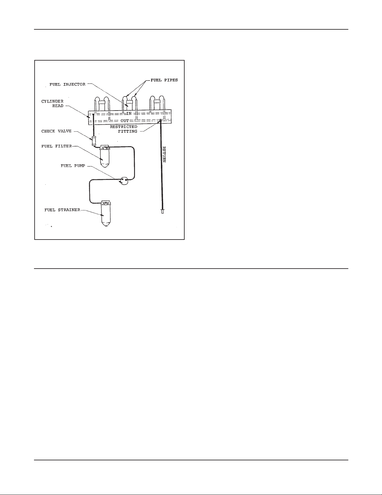
FUEL SYSTEM
OPERATION
Fuel is drawn from the supply tank through the fuel strainer
and enters the fuel pump at the inlet side. Upon lea ving the
fuel pump under pressure, the fuel is forced through the fuel
filter and into the fuel inlet manifold where it passes through
fuel pipes into the inlet side of each fuel injector. The fuel is
atomized through small injector spray tip orif ices into the
combustion chamber. Surplus fuel, returning from the injectors, passes through the fuel return manifold and connecting
fuel lines back to the fuel tank. The continuous flow of fuel
through the injectors helps to cool the injectors and to
remove air from the fuel system.
CHECK VALVE
A check valve is installed between the fuel filter and the fuel
inlet manifold. The check valve is rated to open at approximately 2 psi (13.7 KP A). The fuel tank and supply lines
should be arranged to limit static pressure so that the v alve
remains closed when unit is not running. This valve opens
automatically from fuel pump pressure when the unit starts.
Refer to Figure 1, Page 14, for fuel system components.
FUEL INJECTOR
model being operated, make special note of the certif ied
engine operating speed (RPM). Much of the data v aries by
operating RPM - check the FM/UL/ULC certification tag on
the engine flywheel housing for this speed.
Since the injector is one of the most important and carefully constructed parts of the engine, it is recommended that
the injector be replaced as an assembly if it is not operating
properly. An authorized DDC Distributor/Dealer is equipped
to pro vide ne w and reconditioned replacement injectors.
Under no circumstance should an attempt be made to repair
these injectors. Genuine f actory new or "reliabilt" injectors
should be used for repairs.
FUEL PUMP
DDFP Engines are equipped with a positi ve displacement
gear type fuel transfer pump. Fuel pumps are furnished in
either left or right hand rotation according to the engine
model, and are stamped RH or LH. These pumps are not
interchangeable and cannot be rebuilt to operate in an opposite rotation. The fuel pump used on the 53 series engine is
driven by the go vernor assembly on the left rear . On I-71 it
is attached and driven off the rear of the lower engine blower rotor. On VEE engines, the pump is attached and dri ven
off the right front blo wer rotor located on the v ee of the
block.
A spring-loaded relief valve, incorporated in the pump body,
normally remains in the closed position, operating only
when the pressure on the outlet side (to the fuel f ilter)
becomes excessive due to a plugged filter or fuel line.
The fuel injector combines in a single unit all of the parts
necessary to pro vide complete and independent fuel injection at each c ylinder. The injector creates the high pressure
necessary for fuel injection, meters the proper amount of
fuel, atomizes the fuel, and times the injection into the combustion chamber.
The fuel pump incorporates two oil seals. Two tapped holes
are provided in the underside of the pump body, between the
oil seals, to permit a drain tube to be attached. If fuel leakage exceeds one drop per minute, the seals must be replaced.
An authorized DDC Distributor/Dealer is properly equipped
to replace the seals or to provide reconditioned parts.
Page 12
Page 18

SECTION 3.1 DDFP
SPIN-ON TYPE FUEL FILTER
A spin-on type fuel strainer and fuel filter (Fig. 2) is used on
Clarke DDFP engines. The spin-on filter cartridge consists
of a shell, element and gasket combined into a unitized replacement assembly . No separate springs or seats are required to support the filters.
The filter base incorporates a threaded slee ve to accept the
spin-on f ilter cartridges. The w ord "Primary" or
"Secondary" is cast on the fuel strainer base for identif ication.
No drain cocks are pro vided on the spin-on f ilters. Where
water is a problem, residue may be drained by removing and
inverting the filter. Refill the filter with clean fuel oil before
reinstalling it. Should water be found, locate the source and
correct by draining or cleaning as required.
Replace the Filter as Follows:
1. Unscrew the filter (or strainer) and discard it.
2. Fill a new filter replacement cartridge full with clean fuel
oil. Coat the seal gasket lightly with clean fuel oil.
3. Install the new filter assembly and tighten it to two-thirds
of a turn beyond gasket contact.
4. Start the engine and check for leaks.
General Fuel
Classification
Gravity, °API #
Flash Point, Min. °F (°C)
Viscosity, Kinematic
cST @ 100°F (40°C)
Sulfur Content wt%, Max.
Carbon Residue
on 10%, wt%, Max.
Accelerated Stability
Total Insolubles
mg/100 ml, Max. #
Ash, wt%, Max.
Cetane Number, Min. +
Cetane Index, Min. +
ASTM
Test
D 287
D 93
D 445
D 1266
D 524
D 2274
D 482
D 613
D 4737
No. 2
ASTM 2-D
33 - 37
125 (52)
1.9 - 4.1
0.5
0.35
1.5
0.01
45
40
NOTE: DDFP engines have the "Primary" filter at or below
the fuel pump. One exception to this is current production I-53 engines. Due to f actory designed,
formed steel fuel lines, the I-53 filters are mounted
the reverse of all others. The Primary Filter mounts
to the c ylinder head abo ve the pump. The
Secondary filter mounts to the coolant w ater inlet
elbow below the fuel pump. Inlet fuel check valves
are always located on the discharge side of the secondary filter.
DIESEL FUEL RECOMMENDATIONS
The quality and grade of fuel used is a very important factor
in obtaining satisf actory engine performance, long engine
life, and acceptable e xhaust emission le vels. Certif ied
engine ratings are based at standard SAE conditions using
the recommended #2-D Diesel Fuel. Refer to the Diesel Fuel
Specifications chart Fig 3 for verification of fuel properties.
For additional information on the fuel system, see technical
data Section 5, Page 43. In addition, Sulfur content of the #2
Diesel Fuel used must be limited to 0.5% mass. The com-
Distillation Temperature,
°F (°C)
IBP, Typical #
10% Typical #
50% Typical #
90% +
End Point #
Water & Sediment
%, Max.
# Not Specified in ASTM D 975 ........................................
+ Differs from ASTM D 975
Fig. 3 - Diesel Fuel Specifications Chart
D 86
D 1796
375 (191)
430 (221)
510 (256)
625 (329) Max.
675 (357) Max.
0.05
Page 13
Page 19
SECTION 3.1
DDFP
FUEL SYSTEM SCHEMATICS
1. Fuel Strainer (Primary)
2. Fuel Transfer Pump
3. Fuel Filter (Secondary)
4. Check Valves
5. Cylinder Head with Internal Manifolds
6. Fuel Injectors
7. Fuel Pipes (Inlet and Return to Injector)
8. Restricted Fuel Fitting
Fig. 1 - DDFP Fuel System
ENGINE MECHANICAL GOVERNOR
A v ariable speed mechanical go vernor pro vides speed
control of the engine. The certified engine speed, shown on
FM/UL/ULC label, has been preset at the f actory. Minor
speed adjustments can be made in the f ield to meet specif ic
installation condition, generally ± 50 RPM maximum.
9. Return to Tank
The go vernor is controlled by the R UN-STOP solenoid.
This solenoid is activated by a signal from the AEC. A manual over-ride switch on the instrument panel, placed in the
MANUAL position, allows manual operation should the
AEC malfunction.
Note: Always leave the instrument panel switch in the
AUTO position when the unit is unattended.
Page 14
Page 20
SECTION 3.1 DDFP
MAINTENANCE AND SERVICE PROCEDURES
Weekly
1). Fuel Tank: Keep the fuel tank f illed to reduce condensation to a minimum. Open drain at the bottom of the
fuel tank once a week to drain of f any possible w ater
and/or sediment. Fill tank after each test run.
NOTE: Per NFPA 20 standards, the fuel tank level must
never be less than 50% of capacity.
2). Fuel: Use a proper grade of #2-D diesel fuel only.
6 Months
Check condition of fuel lines for fraying, leaks or poor condition. Replace as necessary.
Yearly
Change primary and secondary fuel filters. Refer to Section
6 for recommended part numbers.
DIESEL FUEL CONTAMINATION
The most common form of diesel fuel contamination is
water. Water is harmful to the fuel system and it also pr omotes the growth of microbiological organisms (microbes).
These microbes clog fuel f ilters with a "slime" and restrict
fuel flow.
Water can be introduced into the fuel supply through poor
maintenance (loose or open fuel tank caps), contaminated
fuel supply or condensation.
Condensation is particularly prevalent on units which stand
idle for e xtended periods of time, such as f ire pump units.
Ambient temperature changes cause condensation in partially filled fuel tanks.
Water accumulation can be controlled by mixing isoprop yl
alcohol (dry gas) into the fuel oil at a ratio of one pint per
125 gallons fuel (or 0.10% by volume).
Microbe growth can be eliminated through the use of commercially available biocides. There are tw o basic types on
the mark et. The w ater soluble type treats only the tank
where it is introduced. Microbe growth can start again if fuel
is transferred from a treated to an untreated tank. Diesel fuel
soluble type, such as "Biobor" manufactured by U.S. Borax
or equivalent, treats the fuel itself and therefore the entire
fuel system. Please follow manufacturer's recommendations
on useage of these materials.
Engine Out of Fuel
The problems of restarting an engine that has run out of fuel
involves the entire fuel system. After the fuel is e xhausted
from the fuel tank, fuel is then pumped from the primary
fuel strainer and sometimes partially removed from the secondary fuel filter before the fuel supply becomes insufficient
to sustain engine firing.
To ensure prompt starting and smooth running, the fuel system must be pur ged of air and full of fuel from the supply
tank to the restricted fitting at the fuel return line. To accomplish this, a manual priming pump, such as tool P/N J5956
or an electrical type priming pump can be adapted easily to
the fittings provided on the secondary f ilter. To be sure the
injectors are lubricated, priming through the secondary filter
is preferred. The system should be primed until no air is present in the fuel flow from the return line. Pressure should not
exceed 15 psi (103kPa) for ease of handling and safety reasons.
Priming is not al ways necessary if the f ilter elements are
filled with fuel when installed and the fuel manifolds in the
head are not drained of fuel. Prolonged use of the starter
motor and engine fuel pump to prime the system can result
in damage to the starter, fuel pump, injectors and erratic running of the engine, due to the amount of air in the lines and
filters from the supply tank to the c ylinder head.
NOTE: Under no circumstances should a starting aid
such as ether be used to run the engine until the
fuel system is primed. Injector damage will
occur if this method is used. The heat generated
by the external fuel source will cause the tips to
be damaged when the fuel cools them. The
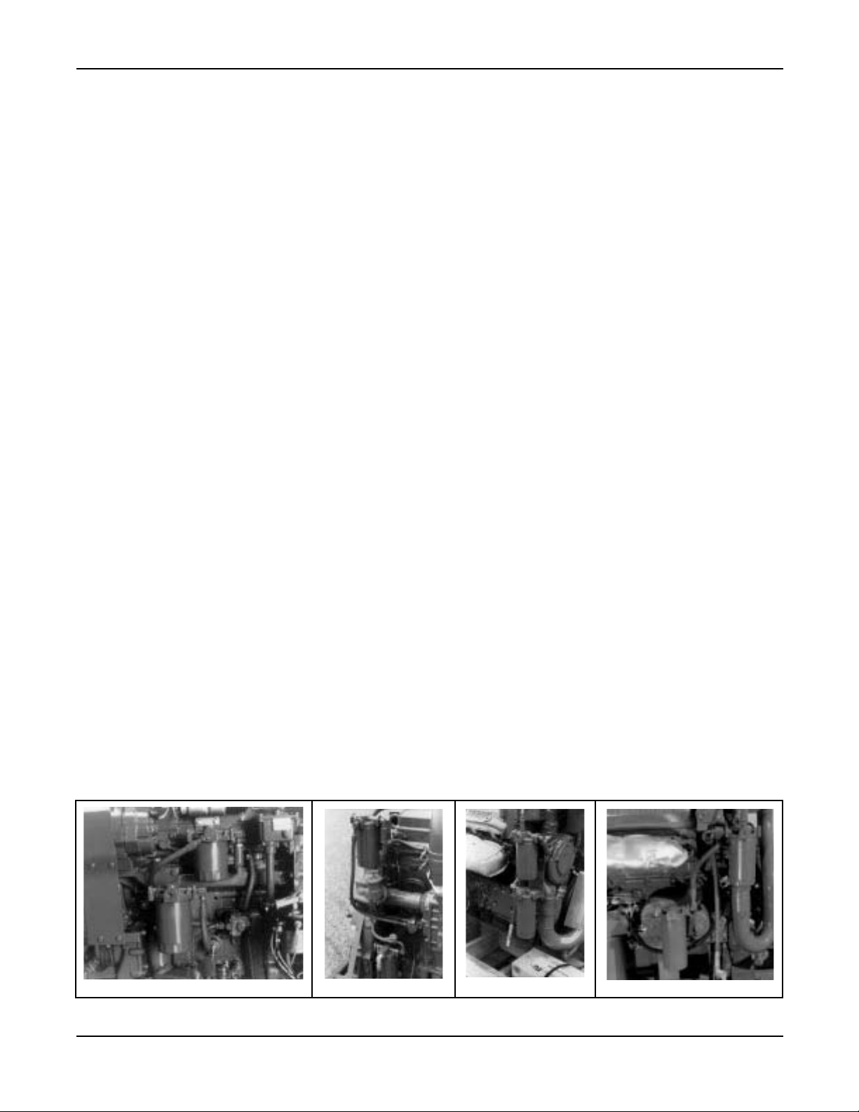
I-53 Fuel Filters I-71 Fuel Filters V-92 Fuel Filters V-71 Fuel Filters
Figure 2
Page 15
Page 21

SECTION 3.2
AIR INTAKE AND EXHAUST SYSTEM
AIR INTAKE OPERATION
In the scavenging process employed in the engines, a charge
of air is forced into the c ylinders by the blo wer and thoroughly sweeps out all of the b urned gases through the
exhaust v alves. This air also helps to cool the inter nal
engine parts, particularly the e xhaust valves. At the be ginning of the compression strok e, therefore, each cylinder is
filled with fresh, clean air which provides for efficient combustion.
AIR CLEANER
The air cleaner used on DDFP engines is either a dry type or
the reusable type. Should a situation occur where the air
cleaner becomes plugged with dirt (starving the engine for
air), low power and heavy black smoke will be the result; the
air cleaner should be serviced immediately.
CAUTION: Do not attempt to remo ve the air cleaner
while an engine is running nor run the engine
while the air cleaner is of f. Exposed turbocharger could cause se vere injury to personnel and major internal engine damage could
occur should an y foreign matter be dra wn
into the engine.
DDFP
The air, entering the blower from the air cleaner , is pick ed
up by the blo wer rotor lobes and carried to the dischar ge
side of the blower as indicated by the arro ws in Figure 1 &
2, Page 1. The continuous dischar ge of fresh air from the
blower enters the air chamber of the c ylinder block and
sweeps through the intake ports of the cylinder liners.
The angle of the ports in the c ylinder liners creates a uniform swirling motion to the intak e air as it enters the c ylinders. This motion persists throughout the compr ession
The air cleaner manufacturer recommends the following:
1. On engines using dry elements, replace the air cleaner
element.
2. On engines with pre-oiled elements, service with a special oil. These elements can be serviced or replaced. Part
number is shown in the parts section of this manual.
3. When servicing the element is not practical, you can improve filter efficiency by re-spraying with oil.
NOTE: Do not attempt this while engine is running.
NOTE: Do not over oil.
Page 16
Page 22
SECTION 3.2 DDFP
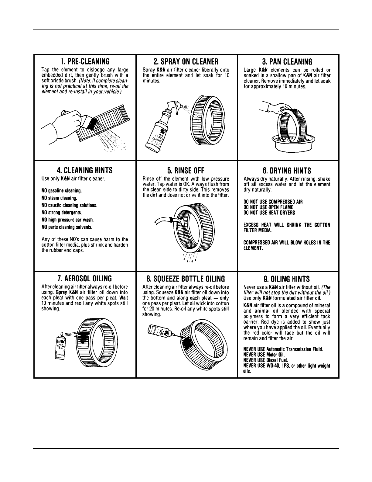
AIR FILTER SERVICE INSTRUCTIONS
Figure 1 - Air Filter Service Instructions
Page 17
Page 23
SECTION 3.2
AIR BOX DRAINS
DDFP
During normal engine operation, water v apor from the
intake air, as well as a slight amount of fuel and lubricating
oil fumes, condenses and settles on the bottom of the air
box. This condensation is remo ved by the air box pressure
through air box drain tubes mounted on the side of the cylinder block.
CRANKCASE VENTILATION
Harmful vapors which may form within the engine are removed from the crankcase, gear train, and injector compart-
Liquid accumulation in the air box will result if a drain tube
becomes plugged. Remo ve the drain tubes and connectors
from the c ylinder block and clean them thoroughly when
necessary.
ments by a continuous, pressurized ventilation system.
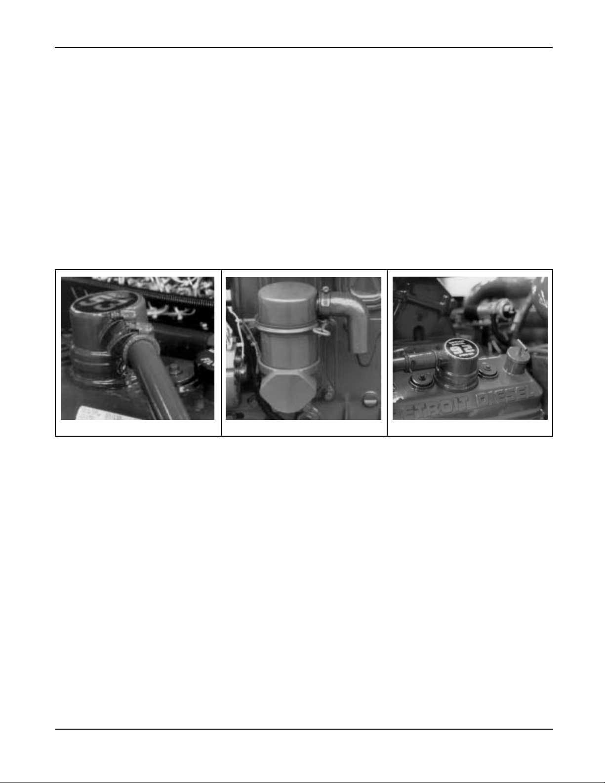
I-53 V71 or V-92I-71
Figure 2 - Crankcase Ventilation
A slight pressure is maintained within the engine crankcase
and injector compartment. This crankcase pressure and resulting ventilation is accomplished by the air seepage past
the piston rings sweeping up through the flywheel housing
and/or the balance weight co ver into the v alve and injector
rocker arm compartment. Here it is e xpelled through a vent
pipe attached to the rock er cover breather assembly . Turbo
charged I-71 engines additionally use a breather attached to
the front left side of the c ylinder block. Figure 2 sho ws the
vent system for each engine series.
Page 18
Page 24

SECTION 3.2 DDFP
EXHAUST OPERATION
Internal comb ustion engines con vert fuel ener gy into both
useful w ork and w asted heat. The useful w ork is the flywheel rotation that dri ves the pump. The w asted heat
involves the engine water cooling system, radiated heat and
the exhaust gases. Approximately 2/
3 of the fuel ener gy is
wasted. Critical re view must be made of these systems to
assure that the engine delivers the useful power required and
maintains the engine within the operating parameters established by the engine manufacturer.
The exhaust system is critical to the proper engine performance. When initially installed, consideration must be gi ven
to the exhaust gas flow requirements, the exhaust temperatures and the e xhaust back-pressure limitations of the specific engine. Generally , N engines can tolerate a higher
exhaust pressure than T engines. Refer to Section 5 for specific engine model and operating speed back-pressure limitations. All the components in an exhaust system contribute
to the back-pressure determination including the fle x
exhaust section, muffler, exhaust piping and its conf iguration. In addition to providing engine exhaust data and backpressure limitations, Clarke of fers a service to installers,
through the local Pump OEM Dealer , for making recommendations on e xhaust system sizing for specif ic installations.
MAINTENANCE AND SERVICE PROCEDURES
Weekly
Prior to each maintenance run mak e a visual check of the
exhaust system to v erify condition of piping and muf fler (if
used). Investigate thoroughly any areas that w ould appear to
have rusty conditions such as rain w ater running do wn pipe
and getting inside the engine. Se vere internal engine damage
could occur.
Inspect the engine air cleaner for dirt b uildup or damage.
During actual maintenance run check engine crankcase ventilation tube for excessive blow-by or pressure.
If the exhaust system should become restricted, the hot exhaust gases cannot escape from the engine. This condition
would cause a loss of po wer, extreme internal engine heat,
and v ery high e xhaust gas temperatures. These conditions
can and will cause internal cylinder damage and a reduction
of engine life.
Some engines are turbocharged (T). Turbochargers increase
the air flo w into the engine c ylinder and permit increased
horsepower by burning more fuel than is possible in a naturally aspirated (N) engine. Turbochargers enhance the ef ficiencies of engines and add power to a similar displacement
(N) engine.
Basically, turbochargers are maintenance free. Ho wever,
should any exhaust manifold studs or bolts break or come
loose, engine exhaust gases can start leaking into the pump
room. Under these conditions, the engine should be attended to immediately . First indications of an e xhaust leak
would be the smell of diesel exhaust and possible eye irritation. Unless f ire pump maintenance personnel are well
versed in a repair of turbochar gers and e xhaust systems,
contact your local Distributor/Dealer for assistance.
NOTE: Exhaust back pressure, air inlet restriction and
crankcase pressure limits are listed for each
DDFP Model in Technical Data Section 5. These
limits are not to be e xceeded. To properly check
these limits, the engine must be producing maximum required horsepower.
While the engine is running inspect e xhaust pipe outlet outside of the pump room itself for en vironmental hazards such
as excessive smoke conditions. The following could be used
as a guide for general engine operating conditions.
1. Blue Smoke — Possible engine oil consumption - too
many areas to list for possibilities.
2. White Smoke — Possibility of water in cylinders
Source — Possible w ater in fuel or internal engine prob-
lem.
6 Months
Inspect exhaust system for leaks or plugging,if any are found,
repair immediately. Inspect and tighten if necessary e xhaust
manifold, turbo mount (if equipped) and piping bolts/n uts.
NFPA 37 requirements are to ha ve the e xhaust system co vered with high temperature insulation for personnel protection. Inspect the insulations condition for any deterioration or
looseness, repair as necessary.
Exhaust system back pressure limits are not to be e xceeded.
Should any of these or any other conditions be found, contact
your local DDC Distrib utor/Dealer for assistance. Check
condition of the air inlet system ducting, clamp tightness hose
condition.
Yearly
Clean and re-oil the air cleaner element per the manufacturers
directions. Each engine is shipped with the cleaning instructions. Refer to Figure 1, page 17.
Check crankcase v entilation tube for proper operation by
making a visual inspection while engine is running.
Page 19
Page 25

LUBRICATION SYSTEM
DDFPSECTION 3.3
OPERATION
The lubricating oil system is schematically illustrated in
Figures 1, 2 and 3 for the Inline and VEE engines. The system consists of an oil pump, oil cooler, a full-flow oil filter,
by-pass valves at the oil cooler and filter, and pressure regulator valves at the pump and in the c ylinder block main oil
gallery. Positive lubrication is ensured at all times by this
system.
Oil for lubricating the connecting rod bearings, piston pins,
and for cooling the piston head, is pro vided through the
drilled hole in the crankshaft from the adjacent forw ard
main bearings. The gear train is lubricated by the o verflow
of the oil from the camshaft pock et through a connecting
passage into the flywheel housing from the camshaft, balance shaft, and idler gear bearings. The blower drive gear
bearing is lubricated through an e xternal pipe from the rear
horizontal oil passage of the cylinder block.
On the Inline engines the oil from the cam pocket enters the
blower and overflows through two holes, one at each end of
the blo wer housing, providing lubrication for the blo wer
drive gears at the rear end and for the go vernor mechanism
at the front. On the VEE engines, the blower drive gear is
lubricated from the rear of the blower.
OIL COOLER
All engines use a plate type oil cooler. Between each engine
model, the major difference lies in the number of plates in
each cooler. The number of plates required is determined by
engine horsepo wer de veloped. All the oil cooler systems
incorporate oil bypass valves in the event of plate core plugging.
It should be understood that improper engine maintenance
could adversely effect the ef ficiency of the oil cooler system. Please refer to the technical data Section 5, for specific lube oil temperature and engine coolant temperature
ranges for each engine model.
LUBE OIL FILL
On I-71 engines, the oil f ill is located on the right rear . On
the VEE engines, it is found in the right bank v alve rocker
cover. On the 53 Series engine, the oil fill is also located on
the rocker cover. See technical data, Section 5 for oil v olumes and specif ications on each engine model. A typical
oil fill location is shown in Figure 5, Page 24.
LUBE OIL PUMP
The positive displacement gear type pump is mounted to the
main bearing caps on I-71 and dri ven from the front end of
the crankshaft. On the I-53,V-71 and V-92 engines the pump
is found in the lower front cover and driven by the front end
of the crankshaft. The I-71, V-71 and V-92 have a pressure
relief located on the dischar ge side of the pump, which
maintains pressure being delivered to the oil filter and cooler. The I-53 engine does not use a pressure relief v alve but
does incorporate the use of the f ilter and oil cooler bypass
valve to maintain pressure.
All four engines use an oil pressure regulator valve to maintain oil g alley minimum pressures. See technical data
Section 5 for specifics per engine model.
OIL LEVEL DIPSTICK
On most DDFP engines, the dipstick is located on the lower
left side. Exceptions are the I-71 and 12V92 models where
the dipstick is located on the right. Oil level can be checked
only when the engine is at rest (not running). Oil levels must
be maintained between the low and full marks.
NOTE: Due to the basic engine design, DDC engines
retain large volumes of oil in the block while
running. For this reason, proper oil level cannot
be checked immediately after engine shut of f.
Wait approximately 10 minutes before checking oil le vel. Do not add oil to a running
engine; overfilling can occur!
Page 20
Page 26
SECTION 3.3 DDFP
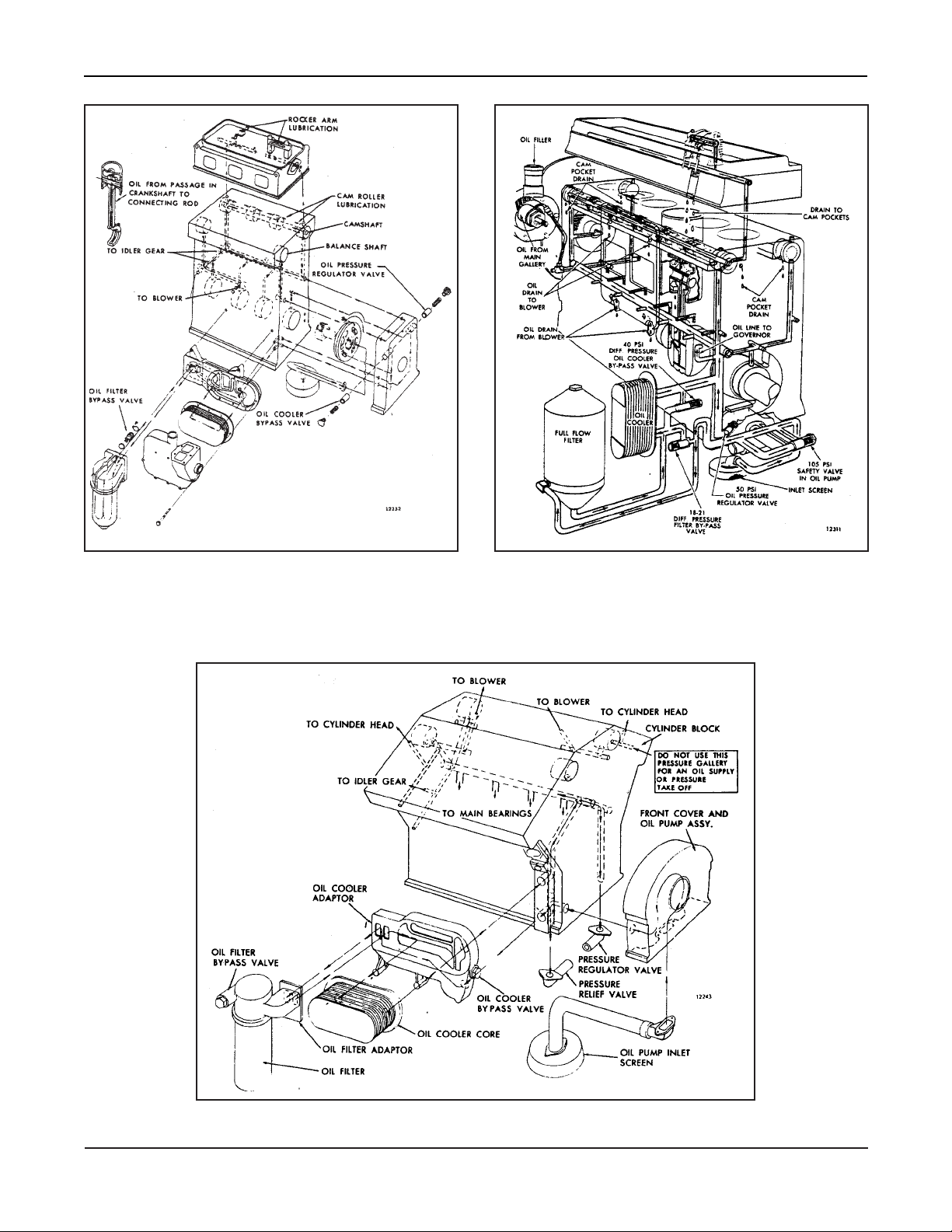
Fig. 1 - I-53 Lubricating System Schematic
Fig. 2 - I-71 Lubricating System Schematic
Fig. 3 - V-71 & 92 Lubricating System Schematic
Page 21
Page 27
SECTION 3.3
DDFP
LUBE OIL FILTER
All engines use full flow oil filters of the "spin on" type element. They have a non-replaceable pleated paper cartridge.
Each filter has an integral bypass valve in the event of plugging or for cold start purposes.
NOTE: Use only appro ved f ilters with the recom-
mended filtration micron rating. See parts list
Section 6 for proper service part numbers.
Replacing Spin on Oil Filter(s)
1. Obtain the Detroit Diesel recommended replacement
lube oil filter. See Chart, Page 44.
2. Use a properly sized oil f ilter wrench, such as
Kentmoore P/N J24783, and remove filter(s).
3. Discard used filter(s) as recommended by EPA.
4. Clean the f ilter base mounting surf ace with a lint free
cloth.
5. Lightly coat the oil filter seal with clean engine oil.
specify a Mil-L-2104F type oil. Because the y may display
different viscosity grades, it is necessary to use a SAE 40
grade only.
TWO-CYCLE ENGINES
DETROIT DIESEL SERIES 53, 71, 92
LUBRICANT REQUIREMENTS
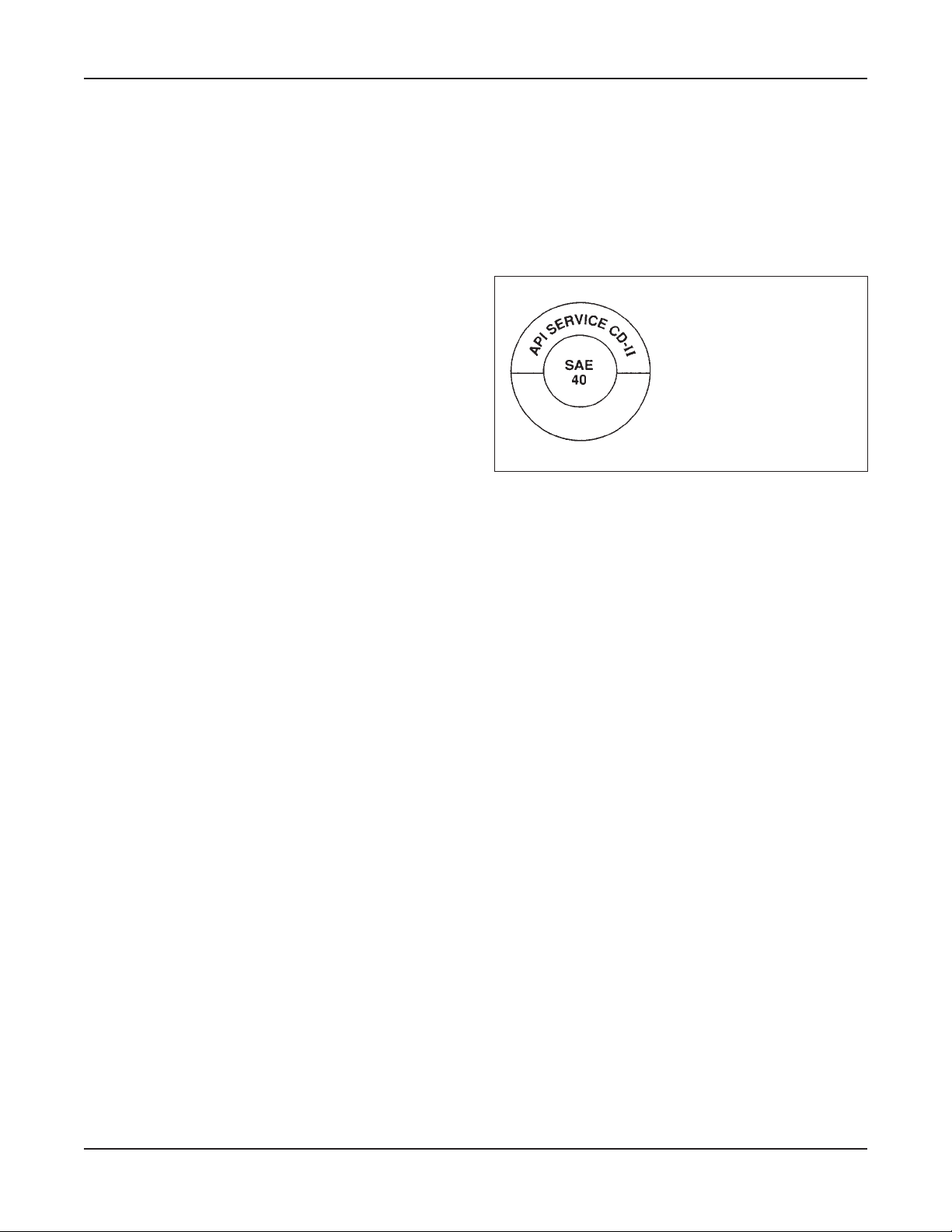
API Symbol:
*
SAE Viscosity Grade: 40
API Classification: CDII or CF2
*CF-2 when available
This is the only oil recommended for Detroit Diesel Engines
used in DDFP service. Lubricants meeting these criteria
have provided maximum engine life when used in conjunction with recommended oil drain and f ilter maintenance
schedules.
Sulfated Ash: less than 1.0%
6. Start threading the ne w replacement f ilter onto the
threaded portion of the base and hand tighted until the
seal contacts the filter head. With the filter wrench, continue to tighten two-thirds of a turn.
7. Start engine and check for leaks. If any are found do not
put engine into service until corrections are made.
LUBRICATING OIL REQUIREMENTS
Hundreds of commercial oils are marketed today, but labeling terminology differs among suppliers and can be confusing. Some mark eters may claim that their lubricant is suitable for all mak es of diesel engines and may list engine
makes and types, including Detroit Diesel, on their containers. Such claims, by themselves, are insufficient as a method
of lubricant selection for DDFP engines.
The proper lubricating oil for all DDFP engines is selected,
based on SAE Viscosity Grade and API (American
Petroleum Institute) Service Designation. Both of these
properties are displayed in the API Symbol, which is illustrated within the specif ic requirements. For DDFP engines,
the proper lubricant must also possess a sulfated ash content
below 1.0% mass.
Lubricating oils for Non-T actical Military usage currently
Certain engines operating conditions may require e xceptions to this recommendation. They are as follows:
1. For continuous high temperature operation (o ver 100° F
38° C Ambient), the use of SAE 50 grade lubricant in all
DDFP engines is recommended.
2. The API Performance Cate gory CF2 represents an enhanced level of lubricant performance o ver CD-II category which it replaces. Lubricants meeting this new performance level may not be readily available. During this
interim period oils labeled as API CD-II may be used.
3. When the use of High Sulfur Diesel Fuel (greater than
0.5% mass) is una voidable, the use of lubricants with
higher Total Base Numbers (alkalinity) are recommended. Refer to Fig. 4 for minimum TBN numbers to be
used for normal service.
MAINTENANCE AND SERVICE PROCEDURE
Weekly
1). Check oil le vel with the engine stopped. Please refer to
"note" listed in Section 3 under oil le vel dipstick for
proper oil level check.
Page 22
Page 28

SECTION 3.3 DDFP
2). During and after weekly maintenance run, check o ver
entire engine for signs of oil leaks. Repair immediately
if found or call your authorized DDC Distributor/Dealer
for service.
NOTE: If oil is observed coming from the air box drain
tubes while running, review maintenance procedure on page 19.
Yearly
Stationary diesel engines collect condensation in the engine
oil pan while at rest. When in use, lubricating oil undergoes
deterioration from combustion by-products and contamination. For these reasons, regardless of the appearance of the
oil, change oil and filter(s) annually.
TWO CYCLE ENGINES ONLY
ASTM
Designation
Pentane Insolubles
D 893
% Max.
Carbon (Soot) Content,
E-1131
TGA Mass % Max.
CAUTION: Use only recommended lube oil and oil f ilters. Internal engine damage and/or excessive wear could
occur using unauthorized materials.
LUBRICATING OIL ANALYSIS
Oil Analysis kits are available through the DDC Distributor
Network for ef ficient monitoring of the lubricating oil in a
DDFP engine. Refer to Parts Information Section 6 to order.
Oil Analysis consists of a series of laboratory tests conducted on the engines lubricant. Some tests sho w the condition
of the engine and others show the condition of the lubricant.
Refer to Fig. 4 for warning limits.
Condition
Measured
Engine
53, 71, 92
1.0
Combust.
Engine
0.8
Combust.
Viscosity at 40°C cS
% Max. Increase
% Max. Decrease
Total Base Number (TBN)
Min.
Min.
Water Content (dilution)
Vol. % Max.
Flash Point °C
Reduction Max.
Fuel Dilution Vol. % Max.
Glycol Dilution
PPM Max.
Iron Content
PPM Fe Max.
Copper Content
PPM Cu Max.
Sodium Content PPM NA
Over Baseline Max.
Boron Content PPM B
Over Baseline Max.
D 445 & D 2161
D 664 or D4739
D 2896
D 95
D 92
*
D 2982
**
**
**
**
Engine & Oil
Oil
Engine
Engine
Fuel Dil.
Engine
Engine
Engine
Wear
Engine
Wear
Engine
Coolant
Engine
Coolant
40.0
15.0
1.0
2.0
0.30
20.0
2.5
1000
150
25
50
20
** Various Methods
** Elemental Analyses are conducted using either emission or atomic absorption spectroscop y. Neither method has an ASTM designation.
Fig. 4 - Oil Analysis Warning Limits
Page 23
Page 29

SECTION 3.3
OIL VOLUME
For specific oil quantities please refer to Technical Data Section 5 for each engine model listing.
DDFP
▼
Fig. 5 - Typical Oil Fill Location
Page 24
Page 30

SECTION 3.4 DDFP
COOLING SYSTEM
The Engine Cooling System Includes:
Coolant Pump
Heat Exchanger with Overflow Pipe
Oil Cooler
Pressure Cap-Fill Cap
Thermostat & Water Bypass
Raw Water Inlet and Discharge
Zinc Electrode
OPERATION
The heat resulting from combustion in the engine cannot be
fully converted into kinetic ener gy. A major portion of that
heat is absorbed by the coolant from the c ylinder walls and
cylinder heads and must be carried away from the engine. It
is the function of the Heat Exchanger to transfer w aste
engine heat to the raw cooling water.
Inside the heat e xchanger tank Fig. 1 is a heat e xchanger
core, somewhat similar to a miniature radiator . Engine
coolant circulates around the heat exchanger core while cool
raw water, from a tap on the pressure side of the f ire pump,
is circulated inside the core carrying a way the heat. The installing contractor mak es the ra w water discharge connection at time of system installation.
V-71
I-53
Fig. 1 - Heat Exchanger Cooling System
V-92
I-71
Page 25
Page 31

SECTION 3.4
DDFP
Engine coolant is circulated by the engine coolant pump.
Engine coolant enters the side of the block upon dischar ge
from the oil cooler and coolant pump. Under lo w pressure,
the coolant flo ws past the c ylinders, up through the heads,
and then through the open thermostat into the heat exchanger tank. After passing o ver the heat e xchanger core, the
coolant then re-enters the coolant pump and starts the c ycle
over. If the thermostat is closed, coolant would flow down a
bypass tube, back to the coolant pump. Under that condition,
the coolant bypasses the heat exchanger core and allows the
engine to retain some of the heat so it can quickly reach optimum operating temperature.
ENGINE COOLANT
The following information is provided as a guide for Detroit
Diesel engine users in the selection of a suitable coolant.
The water/ethylene glycol/inhibitor coolant mixture used in
DDFP engines must meet the following basic requirements:
• Provide for adequate heat transfer.
• Provide protection from cavitation damage.
• Provide a corrosion/erosion resistant environment within
the cooling system.
• Prevent formation of scale or sludge deposits in the cooling system.
• Be compatible with engine hose and seal materials.
• Provide adequate freeze and boil over protection.
WARNING
A 50% water and 50% anti-freeze solution is
required for pump installations. Premixing
this solution prior to installing is required.
This prevents possible pure anti-freeze chemical reactions to block heater elements which
can burn out the element. Please see the technical data Section 5 for proper cooling system capacities of each model.
tory as an engine coolant when properly inhibited. Use of
distilled water is ideal.
GRAINS PER
Chlorides (Maximum)
Sulfates (Maximum)
Total Dissolved Solids (Maximum)
Total Hardness (Maximum)
GALLON
40
100
340
170
PA RTS PER
MILLION
2.5
5.8
20
10
Fig. 2 Satisfactory Water Limits
ANTIFREEZE
Use an eth ylene glycol coolant (lo w silicate formulation)
that meets or exceeds the standard of either the GM 6038-M
formulation (GM 1899-M performance) or ASTM D 4985
requirements.
A 50% coolant/water solution is normally used. Concentrations over 70% are not recommended because of poor heat
transfer capability , adverse freeze protection and possible
silicate dropout. Concentrations belo w 30% of fer little
freeze, boil over or corrosion protection.
COOLANT INHIBITOR
The importance of a properly inhibited coolant cannot be
over-emphasized. A coolant which has insuf ficient or no
inhibitors at all, invites the formation of rust, scale, sludge
and mineral deposits. These deposits can greatly reduce the
cooling systems efficiency and protection capabilities.
DDC-recommended supplemental coolant inhibitors are a
combination of chemical compounds which pro vide corrosion protection, cavitation suppression, pH controls and prevent scale. These inhibitors are a vailable in v arious forms,
such as liquid packages or integral parts of anti-freeze.
WATER
Water can produce a corrosi ve en vironment in the cooling
system, and the mineral content may permit scale deposits to
form on internal cooling surfaces. Therefore, inhibitors must
be added to control corrosion, cavitation, and scale deposits.
Chlorides, sulfates, magnesium and calcium are among the
materials which mak e up dissolv ed solids that may cause
scale deposits, sludge deposits, corrosion or a combination
of these. Chlorides and/or sulf ates tend to accelerate corrosion, while hardness (percentage of magnesium and calcium
salts broadly classif ied as carbonates) causes deposits of
scale. Water within the limits specif ied in Fig. 2 is satisfac-
It is imperative that supplemental inhibitors be added to all
DDFP engine systems. A pre-charge dosage must be used at
the initial fill and the maintenance dosage used at each service interv al. Serious damage will occur unless inhibitors
are used. Some of the more common corrosion inhibitors
are borates, nitrates and silicates.
Inhibitors become depleted through normal operation, additional inhibitors must be added to the coolant as required to
maintain original strength levels. Refer to Fig. 3 for proper
concentrations of inhibitors.
Do not use soluble oils or chromate inhibitors in DDFP
engines. Detrimental effects will occur.
Page 26
Page 32

SECTION 3.4 DDFP
Max.
PPM
1500
2400
2000
250
500
10.5
Boron (B)
Nitrite (NO2)
Nitrates (NO3)
Silicon (Si)
Phosphorous (P)
pH
Min.
PPM
1000
800
1000
50
300
8.5
Fig. 3 - Proper Concentrations Of Inhibitors
To properly check inhibitor concentrations it may be necessary to contact your local DDC Distributor/Dealer for assistance. Refer to P arts Information Section 6, Page 45, to
obtain the DDC part number for the F actory Coolant
Analysis Kit. This kit can be purchased for nominal fee for
analyzing the condition of the engine's coolant.
PROCEDURE FOR FILLING ENGINE
During filling of the cooling system, air pockets may form.
The system must be pur ged of air prior to being put in service. This is best accomplished by f illing with a pre-mix
solution, to the top of f iller neck. Install the pressure cap,
start and run engine until the temperature staabilizes at
approximately 170° - 190° F (77° - 91° C). During this
warming process, you may
To verify that the coolant is at a safe operating level, it's best
to wait until the engine temperature drops to approximately
120°F (49°C), or lo wer, before removing the pressure cap.
After the cap is removed, the level should be within 2 inches (51mm) of the filler neck.
NOTE: I-71 engines have incorporated the use of a coolant
recovery bottle (white plastic bottle) Fig 4. During
initial filling of the cooling system, it will be necessary to f ill the Reco very Bottle to the Cold Full
line with the pre-mix solution. Start and run the
engine as indicated abo ve. After reaching normal
operating temperature check the coolant le vel in
the recovery bottle to v erify that the le vel is at the
Hot Full line, if not add coolant to the bottle.
Following the same instructions as abo ve, wait for
the engine coolant temperature to drop before
removing the pressure cap. The coolant le vel
should be at the pre viously mention height. The
coolant level must remain between Hot and Cold
run lines on the recovery bottle.
CAUTION: Do not remove pressure cap while coolant is at
normal operating temperatures. Possible personal injury could result from the expulsion of
hot coolant.
PRESSURE CAP
Like most cooling systems, the Heat Exchanger type operates under pressure. A typical cap shown in Fig. 5 maintains
system pressure to raise the coolant boiling point and permits a some what higher operating temperature without
coolant loss. Pressure cap values can vary in different engine
series. Refer to Section 5 for your engine type.
Fig. 4 - Coolant Recovery Bottle
see coolant coming from the o verflow tube attached at the
pressure cap location. This is a normal condition since the
coolant expands as it heats up. When the o verflow ceases,
stop the engine.
NOTE: Air entrapment in I-53 engines is v ery lik ely to
occur due to cooling system design. Upon initial
fill with a pre-mix solution. It is recommended that
the coolant be allowed to stand for a four hour period prior to starting.
All pressure caps include a vacuum valve which opens during cool down. This prevents an internal vacuum from being
formed which could contrib ute to leaking seals and hoses
collapsing.
NOTE: I-71 engines use a coolant reco very bottle. The
pressure cap includes a rubber ring-type seat.
When the cap installed this ring forms a positi ve
seal between the filler neck and cap. During engine
cool down, if the wrong type cap is used, coolant
cannot transfer back into the heat e xchanger from
the recovery bottle. This can progress into an overheated engine and possible damage.
Fig. 5 - Typical Coolant Cap
Page 27
Page 33

SECTION 3.4
DDFP
COOLANT PUMP
The engine water pump is a centrifugal impeller type pump.
It is gear dri ven on the I-71, V-71 and V-92 Series engines
and belt driven on the I-53 Series engines. The rebuildable
pump utilizes a shaft and sealed bearing assembly. The V-71
and V-92 incorporate an oil seal and tw o splash lubricated ball type bearings. Each pump also included a w ater
pump seal weep hole. Should a coolant leak occur at this
location, the pump seal must be replaced. Contact your local
DDC Distrib utor/Dealer for assistance. Should a replacement pump be required for repair , use only the e xact same
type of pump.
THERMOSTAT
Each pump engine is equipped with a temperature controlling thermostat(s). Normal operating ranges will vary due to
engine horsepower and operating speed. The thermostat(s)
are located at the front of the c ylinder heads. Refer to
Section 5 for specif ic operating temperatures for each
engine.
ENGINE COOLANT HEATER
CAUTION: Do not acti vate the AC circuit unless the
engine cooling system has been filled.
A pre-mix solution must be used. Chemical
reactions will occur if pure Ethylene Glycol
anti-freeze is allo wed to f ill the heater ca vity
with AC circuit is activated.
HEAT EXCHANGER COOLING
The heat e xchanger cooling system is illustrated in Fig. 1,
Page 25.
Raw water from the f ire pump passes through the heat e xchanger core where it lowers the engine coolant temperature
10-15° F (-12° – -9° C). Typical raw water connection points
on the heat exchanger are shown in Fig. 7, Page 29.
HOSES
Specific areas on each DDFP engine use hoses to transfer
coolant to and from heat exchangers and immersion heaters.
Regular inspections are necessary to v erify that no leaks
exist. Should replacements be required contact your local
DDC Distributor/Dealer for assistance.
Fire pump engines must be able to assume full load immediately when used for emergency service. NFPA-20 specifications require an engine coolant heater Figure 6, Page 29,
to maintain a minimum temperature of 120° F . (49° C).
Maintaining this temperature assists the engine to start easily and produce rated horsepo wer immediately . F or f ire
pump units operation in cold climates optional oil heaters
are a vailable to k eep the engines lubricating oil at a safe
temperature for emer gency start purposes. If pump room
temperatures drop belo w 50° F (10° C), oil heaters are
required.
On the initial installation of each f ire pump engine, it is the
responsibility of the installing contractor to wire the heater
to the pump room AC circuit. See Section 3 Electrical AC
Wiring Diagram, Page 39, for correct wiring to the heater
disconnect switch.
NOTE: Silicon Hose material for the immersion heaters
must meet SAE J20 Requirements with a maximum heat operating range of 350° F (177° C). Do
not replace these hoses with any other type material.
NOTE: Hose clamps required for silicon type hose, must
have a shielded inner band or be of a constant
torque type (spring loaded). If the second type is
used, do not collapse spring by over tightening.
Page 28
Page 34

SECTION 3.4 DDFP
I-53 V-71 or V-92
Fig. 6 - Engine Heaters
I-53 V-92
V-71 I-71
Fig. 7 - Raw Water Connections
Fig. 8 - Typical Cooling Loop
Page 29
Page 35

SECTION 3.4
DDFP
RAW WATER SYSTEM (Cooling Loop)
This system is provided by the pump manufacturer or pump
assembler as part of the complete engine-pump-controller
package. Components for the raw water system are selected
to ensure adequate flo w through the heat e xchanger as
required by the engine at specif ic ra w w ater temperature.
The raw water system is generally referred to as the "cooling loop". A typical cooling loop includes the follo wing
components as shown in Fig. 8, Page 29;
1. Indicating manual valves
2. Water strainers
3. Pressure regulator
4. Solenoid valve (DC)
5. Pressure gauge
The heat e xchanger discharge line should be one pipe size
larger than the supply line. Additionally, it is recommended
that the discharge line rise a minimum of 3" to maintain raw
water across the entire cooling core. Discharge is made to an
open waste cone as specified in NFPA-20.
CAUTION: Damage to the heat exchanger may result if
raw w ater plumbing (supply or dischar ge) weight or
stress is applied to the heat exchanger.
ZINC ELECTRODE
A sacrifical zinc anode is included with each heat e xchanger. Over a period of time, normal electrotic action will occur
between dissimiliar metals within the heat e xchanger. The
rate of material transfer is dependent on the electrolitic
strength of the transfer media (ra w w ater). It is the zinc
anode that gi ves up material in this process and thus preserves the integrity of the heat exchanger.
MAINTENANCE AND SERVICE PROCEDURES
Weekly
1) Check coolant level weekly. The level should be within
two inches of the filler neck. Because this is a closed system, when operating temperature is reached, the pressure
relief cap may allo w some e xcess coolant to e xpell out
the o verflow tube until a stabilized le vel is reached.
Refer to procedure for filling engine in this section.
Check the condition of the pressure relief cap. The rubber
seat should be in sound condition. If it is crack ed, split or
frayed, do not use. Do not attempt to run engine without a
pressure cap. Each cap has a relief rating, which is not to be
altered if a replacement cap is required. Refer to Section 5
for specific cap type and rating for each engine.
The solenoid valve may be omitted on vertical turbine pump
installations where no static pressure e xists in the heat e xchanger supply line while the engine is not running. Each
engine has a minimum requirement of ra w w ater flo w.
Correct flow through the heat exchanger is critical for maintaining the proper engine operating temperature.
Engine coolant temperature can be adversely affected by insufficient raw water flow and by excessive ambient temperature of the ra w water. See the technical data Section 5 for
each engine model's minimum raw water flow requirements
at 60° F (16° C) and 95° F (35° C) at specified engine RPM
ranges. Do not exceed raw water pressure allowance within
the heat exchanger.
NOTE: Although engine operating temperature may
appear normal, engine cooling may be compromised and possible engine damage will result if
raw water flow is reduced.
2) Inspect all hoses for leaks, repair or replace as necessary.
Annually
Check coolant inhibitor concentration, if not within v alues
shown in Fig. 2 re-inhibite as necessary.
Check Zinc Electrode, if more than half is deteriorated electrode should be replaced. Contact your local DDC
Distributor/Dealer for replacements.
Every Two Years
Change all hoses.
Page 30
Page 36

SECTION 3.5 DDFP
ELECTRICAL SYSTEM
ENGINE OPERATING SYSTEM
The DDFP engines used for f ire pump service include tw o
electrical systems. F irst is the engine heater system (A C),
second is the engine starting system (DC). The starting and
control circuits are integral with the DC wiring harness b ut
are separated for explaining operation, maintenance and service procedures. Engines are supplied with either a 12 or 24
V-DC system. Depending upon the specif ic model (refer to
Section 5). This includes a starting motor, battery charging
alternator, wiring harness, battery insulator, manual contactors, run-stop solenoid and tw o battery systems. F or identification reasons only, usually 12 V-DC systems have 2 batteries, 24 V-DC systems ha ve 4. Under normal operating
conditions, signals for running and shutdown are transmited
from the AEC. With the controller switch on "automatic", a
specific drop in the fire main line pressure or other pre-programmed signal will result in a start of the diesel engine.
Reference the DC wiring diagram Fig. 13, Page 37 or Fig.
14, Page 38.
CAUTION: These engines have been pre-set for a specif ic
operational speed (RPM). When started, the
engine will quickly reach this setting. The engines do not have idle speed settings. With the
AEC switch on "T est", the engine can be test
started from the controller using either battery
system A or B. Engine stopping is accomplished by switching the controller selector to
the "Off" position. Consult the AEC operating
manual for specific operational instructions.
ENGINE HEATERS
NFPA-20 specifications require that the engine coolant be
maintained at 120° F (54° C) minimum. Additionally, if the
pump room temperature should fall below 50° F (10° C), an
engine oil heater is recommended. Both coolant and oil
heaters use AC power.
All Clarke DDFP engines include immersion heaters. Typically these heaters are mounted at the front of the engine.
Some models ha ve horizontal mounting and others are
mounted vertical. See Fig. 6, Page 29. Heater w attage ratings v ary with engine size. (Refer to Section 5). These
heaters are wired to an AC junction box mounted on the
engine.
CAUTION: SHUT OFF AC VOLTAGE BEFORE
SERVICING ENGINE HEATER
NOTE: Prior to turning the AEC to an y position other
than automa tic, please read the paragraph
labeled "IMPORTANT" in Section 2, Page 11.
The engine DC starting and control system terminates at the
DC junction box. The junction box location varies on different engine models, one is typically sho wn in Fig. 5. From
this point, the engine is electrically connected to the automatic engine controller (AEC). Both automatic operation
and test signals are sent to the engine from the AEC. Under
emergency conditions, and if the AEC should become defective or disconnected from the engine for an y reason, it is
possible to start the engine by operating the manual contactors. Specific emergency operating instructions are attached
to the instrument panel and explained in detail under MANUAL STARTING of this section. Engine wiring diagrams
for AC and DC systems are shown in this section.
Installation - Jacket Water Heater, Thermostat
Fig. 1
Page 31
Page 37

SECTION 3.5
Fig. 2 - Emergency Operating Instructions Fig. 3 - Automatic - Manual Mode Selector
➞
➞
➞
➞
DDFP
Fig. 4 - Manual Contactors Fig. 5 - DC Junction Box
➞
➞
Fig. 6 - Governor Solenoid
Fig. 7 - Instrument Panel
Page 32
Page 38

SECTION 3.5 DDFP
MANUAL START INSTRUCTIONS
The engine can be operated without using the engine controller. Use the following procedure when manual starting is
required. Refer to Fig. 2, Page 32.
To Start Engine
1. OPEN COOLING SYSTEM MANU AL BYP ASS
VA LVE. Located on the cooling loop, Fig. 8, Page 29.
2. POSITION MODE SELECTOR IN MANUAL RUN.
Fig. 3, Page 32.
3. POSITION BATTERY SELECTOR SWITCH T O
BATT. #1.
4. PULL AND HOLD MANUAL CONTACTOR #1, Fig.
4, Page 32 UNTIL ENGINE ST ARTS, RELEASE
AFTER 5 SECONDS. IF UNIT F AILS TO ST ART,
POSITION BATTERY SELECTOR TO B #2 USE
STARTER CONTACTOR #2, AND REPEAT STEP.
To Stop Engine
1. RETURN MODE SELECTOR TO AUTOMATIC,
AND MANUAL STOP, ENGINE WILL STOP.
INSTRUMENTATION
Figure 7, Page 32 sho ws the instrumentation panel which
contains the follo wing gauges: tachometer with inte gral
hourmeter (1), engine oil pressure (P .S.I.) (2), battery voltmeter (3), engine coolant temperature (°F) (4), battery isolator (5). Engine overspeed switch is mounted to rear of gauge
panel Figure 8.
➞
➞
Fig. 8 - Overspeed Reset
Tachometer and Integral Hourmeter - This meter receives its signal from the o verspeed switch to allow operator
to read engine RPM, in addition the hour meter records a
cumulative total of engine operating hours.
2. CLOSE COOLING SYSTEM MANU AL BY -PASS
VA LVE.
IMPORTANT:
DO NOT LEAVE THE MODE SELECTOR SWITCH
IN THE MANUAL RUN POSITION DURING AUTOMATIC OPERATION. (THE CONTROLLER WILL BE
UNABLE TO STOP THE ENGINE AND OVERHEAT
DAMAGE WILL RESULT)
DO NOT POSITION THE BATTERY SELECTOR
SWITCH TO A DEFECTIVE B ATTERY WHILE IN
THE MANUAL MODE.
GOVERNOR OPERATING SOLENOID
The DC governor solenoid, Fig. 6, Page 32, is an essential
item for the operation of this fire pump system. Upon receiving a signal, the solenoid is energized to move the governor
into the run position.
This solenoid remains ener gized during engine operation.
To stop the engine, the solenoid de-energizes and the governor returns to the "no fuel" position by spring action.
Oil Pressure - This mechanical gauge gives engine oil pressure readings in english and metr ic units (PSI & kP A). Connection location to the engine will vary per engine model.
Engine Coolant Temperature - This temperature gauge
indicates the engines coolant outlet temper ature in de grees
fahrenheit (°F) and centrigrade (°C).
Voltmeter - This gauge identifies the voltage level of the battery according to the position of the ba ttery selector switch.
SPEED SWITCH
After the engine has started and reached 1000 RPM,the speed
switch signals the controller to terminate the starter cranking
action. An overrunning clutch is included on the star ter drive
to prevent damage from overspeeding when the unit star ts.
NOTE: When starting unit with man ual contactor s, re-
lease contactor handle as soon as engine starts.
In the event of an engine o verspeed the speed s witch signals
the AEC and ef fects an engine shutdo wn. A MANU AL
RESET button is included on the switch and must be "pushed
in" to reset the speed s witch after unit has shutdo wn from an
Page 33
Page 39

DDFPSECTION 3.5
overspeed condition. The reset b utton is sho wn in Fig. 8,
Page 33.
NOTE: Engine will not r estart after an o verspeed shut -
down, UNTIL OPERA TOR RESETS THIS
BUTTON. DO NO T ATTEMPT TO RESTART
ENGINE UNTIL VERIFICATION HAS BEEN
MADE AS TO THE REASON FOR O VERSPEED.
A magnetic-pic kup, mounted in the f lywheel housing pr ovides the input signal f or the o verspeed switch. See Fig. 9,
pickup mounting. The magnetic-pickup senses the speed of
the engine by counting the f lywheel ring gear teeth per sec ond. There should be a 0.03" (.762 MM) air gap between the
top of the r ing gear and the ma gnetic pickup. With a gear
tooth aligned with the center of the ma gnetic pic kup hole,
thread the pickup in until it touc hes the gear tooth and then
back it out
pickup in position. Reconnect to wiring harness.
WARNING: All current production DDFP engines use
1
/2 turn. Tighten jam nut while holding the
electronic o verspeed protection controls. Due
to the delicate nature of this devise, it is mandatory that diagnostic probing of the circuitry be
done with the electrical po wer of f. Probing
with any device that causes amperage to exceed
ratings will damage this control. This warning
applies to terminals of the o verspeed switch
and inside the junction box. This type of failure
is not warrantable.
BATTERY CHARGING ALTERNATOR
This belt dri ven engine alternator pro vides po wer to
recharge both battery banks directly through the battery isolator. The battery isolator pre vents backfeed from one battery bank to the other. The alternator is mounted at the front
of the engine as shown in Fig. 10. The alternator is belt driven from the crankshaft or camshaft pulle y.
STARTER
The DC electric starting motor pro vides cranking ef fort to
initiate an engine start. Located on the flywheel housing of
the engine, it is shown in Fig. 11, Page 35.
For automatic operation or test operation, the signal for start
initiation comes from the controller . For manual start at the
engine, activating either contactor #1 or #2 should start the
engine. Re view the MANU AL OPERA TING INSTR UCTIONS for additional details on Page 33.
Fig. 9 - Magnetic Pickup Fig. 10 - Typical Alternator
Page 34
Page 40

SECTION 3.5 DDFP
through a 6 minute c ycle (15 seconds cranking and 15 seconds rest, in 12 consecuti ve c ycles). Battery recommendations are shown for each engine on the respecti ve model in
Section 5.
BATTERY CABLES
Customer Supplied Battery Cables should be sized as recommended in Section 5.
WIRING DIAGRAMS (DC)
Wiring diagrams represented in this section, Figs. 13 and 14
Fig. 11 - Typical Starter
Two alarm switches pro vide condition signal to the engine
controller. First, a coolant temperature switch is pro vided
and mounts on front of right c ylinder head. When the
coolant temperature reaches 205° F (96° C),the switch closes and causes a light to burn and sounds an alarm bell on the
engine controller. Second, an oil pressure switch is pro vided for low oil pressure signal. Should oil pressure drop to or
below 20 P.S.I. (138 kPA) the NC switches closes and causes a light to b urn and sounds an alarm bell on the engineer
controller.
have two basic differences. Other than optional voltage differences of 12V or 24V, the primary difference is the engine
instrumentation. Certain DDFP models use mechanical type
others use electric instruments.
Should it be necessary to diagnose a wiring problem, see
below for identifying which diagram to use.
Fig. 13 Drawing #CO7264 includes Amp Meter with Me-
chanical instruments.
Fig. 14 Drawing #CO7484 includes Volt Meter with Elec-
trical instruments.
Neither a high coolant temperature or a low oil pressure signal will cause the controller to stop the engine. The alarm
bell can be silenced at the controller and an in vestigation
made to determine cause of the signal. The controller lights
will continue to burn until the fault is corrected.
BATTERIES
NFPA-20 requires that fire pump systems include two independent battery units. Each battery bank must ha ve capacity, at 40° F (4.5° C), sufficient to maintain cranking speed
MAINTENANCE AND SERVICE PROCEDURES
ENGINE HEATER
The engine heaters are required by NFP A-20 specif ication
and should maintain the engine coolant at 120° F (54° C).
Check the engine temperature gauge for corresponding performance. See Page 39 for AC wiring, diagram.
A. Condition: - Unit holds minimum 120° F.
Service: - No Service Required
B. Condition: - Unit holds less than 120 F, but above room
temperature.
Service: - One heater element may not be functioning.
Verify which type your engine has before proceeding.
WIRING DIAGRAMS (AC)
The diagram represented in Fig. 15 identifies the AC wiring
requirements necessary for the jack et water heater. An optional lube oil heater is included.
These heaters have optional voltages, depending on installation requirements. Each heater is controlled by a thermostat
mounted in the engine heater.
Check wiring or replace defective element.
C. Condition: - Engine coolant at room temperature
Service: - 1. Check 120V-AC POWER SOURCE.
2. Check wiring connections.
3. Check thermostat function, see Fig. 1.
4. Replace element if defective.
CAUTION: DISCONNECT AC POWER TO HEATER
SYSTEM BEFORE DRAINING ENGINE
COOLANT.
Page 35
Page 41

MANUAL CONTACTORS
Operate contactors to assure manual operation. If o ver-center contact is not functional or if other inoperative condition
exist, replace the UNIT. Check bolts for tightness, wires for
tightness or damage. (Fig. 12).
DDFPSECTION 3.5
BATTERY CHARGING ALTERNATOR
Inspect the terminals for corrosion and loose connections
and the wiring for broken wires. Replace or repair as necessary. Service alternator with authorized Delco service dealer.
WARNING: DO NOT R UN THE I-53 SERIES WITH-
OUT THE ALTERNATOR INSTALLED.
(Drive belts also drive the coolant pump).
New standard V-belts will stretch after the first few hours of
operation. Run the engine for 15 minutes to seat the belts,
then readjust the tension. Check the belts and tighten after
1
/
2 hour and again after 6 months. Thereafter, check the ten-
sion of the dri ve belts e very 6 months and adjust if necessary. Adjust the belt tension so that a f irm push with the
thumb, at a point midw ay between the tw o pulle ys, will
depress the belt 1/2" to 3/4".
STARTER
Fig. 12 - Manual Contactors
MAXIMUM torque for the battery cable studs is 5-10 ft.lbs. DO NOT EXCEED this limitation.
CAUTION Contactors are connected to li ve batteries.
Display appropriate caution with tools.
INSTRUMENTS
Check instruments while running unit to be sure the y are
functional. Replace broken or defective instruments. If hourmeter is replaced, record accumulated hours from replaced
hourmeter.
SPEED SWITCH
This is an electronic unit. If damaged or defective, the entire
switch must be replaced.
Same service and maintenance as recommended for battery
charging alternator. Service starter with an authorized Delco
service dealer.
BATTERIES
Check the specific gravity of the electrolyte in each cell of
the battery each week. In warm weather, however, it should
be check ed more frequently due to a more rapid loss of
water from the electrolyte. The electrolyte le vel should be
maintained in accordance with the battery manuf acturer's
recommendations. K eep all terminals clean and free from
corrosion.
NOTE: Coating terminal connection with petroleum
jelly will prevent rapid corrosion buildup.
WIRING SYSTEM
Annually, open the DC junction box and check tightness of
all terminal connections. Additionally, reference DC wiring
diagram, Fig. 13, 14, Page 37 & 38 and check tightness of
Page 36
Page 42

SECTION 3.5 DDFP
Fig. 13 - DC Wiring Diagram
Engines With Mechanical Guages
Page 37
Page 43

SECTION 3.5
DDFP
Fig. 14 - DC Wiring Diagram
Engines With Electrical Guages
Page 38
Page 44

SECTION 3.5 DDFP
Fig. 15 - AC Wiring Diagram
Page 39
Page 45

FALK DRIVE HUB
DDFP engines are offered with a standard FALK drive hub,
(engine half only). See Page 41 for FALK coupling installation instructions.
If your engine includes this type coupling,please refer to the
following for service and maintenance information.
DDFPSECTION 3.6
Other pump drive options available are vertical turbine drive
shaft adaptor or a standard engine flywheel. Neither of these
require regular maintenance, they are however, very critical
components and should recei ve weekly inspections during
the regular maintenance run.
Steelflex®Couplings
a good name in industry
™
Ty pe T10
How To Use This Manual
This manual provides detailed instructions on maintenance,
lubrication, installation, and parts identification. Use the table
of contents below to locate required information.
TableofContents
Introduction................................................. Page 1
Lube Fittings................................................Page 1
Limited End Float.......................................... Page 1
Lubrication.............................................. Pages 1-2
Installation & Alignment Instructions................. Pages 2-4
Annual Maintenance, Relube & Disassembly...........Page 4
Installation & Alignment Data.............................Page 5
Parts Identification &Parts Interchangeability........... Page 6
CAREFULLY FOLLOW THE INSTRUCTIONS IN THIS
MANUAL FOR OPTIMUM PERFORMANCE AND TROUBLE
FREE SERVICE.
INTRODUCTION
This manual applies to Sizes 1020T thru 1140T and 20T thru
140T10 Falk SteelfIex Tapered Grid Couplings. Unless
otherwise stated, information for Sizes 1020T thru 1140T
applies to Sizes 20T thru 140T respectively, e.g. 1020T = 20T,
1100T = 100T, etc. These couplings are designed to operate
in either the horizontal or vertical position without modification.
Beginning in 1994, these couplings are being supplied with
one set of inch series fasteners and one set of metric fasteners.
Use either set of fasteners, depending on your preference.
Refer to Page 6 for part interchangeability.
The performance and life of the couplings depend largely upon
how you install and service them. Carefully follow the
instructions in this manual for optimum performance and
trouble free service.
CAUTION:
for proper guarding of rotating members. Observe all safety
rules when installing or servicing couplings.
WARNING:
allexternal loads from drive before installing or servicing couplings.
Consult applicable local and national safety codes
Lockout starting switch of prime mover and remove
LUBE FITTINGS
Cover halves have1/
gun and Iube fitting as instructed on Page 4.
NPT Iube holes. Use a standard grease
8
LIMITED END FLOAT
When electric motors, generators, engines, compressors and
other machines are fitted with sleeve or straight roller bearings,
limited axial end float kits are recommended for protecting the
bearings. Falk Steelflex couplings are easily modified to limit
end float; refer to Manual 428-820 for instructions.
Installation and Maintenance
•
Sizes 1020 –1140 & 20–140 (Page 1 of 6)
•
TYPE T10 STEELFLEX COUPLING
LUBRICATION
Adequate lubrication is essential for satisfactory operation. Page
2 provides a list of typical lubricants and specifications for
general purpose and long term greases. Because of its superior
lubricating characteristics and low centrifuge properties, Falk
Long Term Grease (LTG) is highly recommended. Sizes 1020T
to 1090T10 are furnished with a pre-measured amount of
grease for each coupling. The grease can be ordered for larger
size couplings.
The use of general purpose grease requires re-lubrication of the
coupling at least annually.
Long Term Grease (LTG)
The high centrifugal forces encountered in couplings separate
the base oil and thickener of general purpose greases. Heavy
thickener, which has no lubrication qualities, accumulates
in the grid-groove area of Steelflex couplings resulting in
premature hub or grid failure unless periodic lubrication cycles
are maintained.
Falk Long Term Grease (LTG) was developed specifically for
couplings. It resists separation of the oil and thickener and is an
extreme pressure grease.
Steelflex couplings initially lubricated with LTG will not require
re-lubrication until the connected equipment is stopped for
servicing. If a coupling leaks grease, is exposed to extreme
temperatures, excessive moisture, or experiences frequent
reversals, more frequent lubrication may be required.
Although LTG grease is compatible with most other coupling
greases, the mixing of greases may dilute the benefits of LTG.
USDA Approval
LTG has the United States Department of Agriculture Food
Safety & Inspection Service approval for applications where
there is no possibility of contact with edible products. (H-2
ratings).
CAUTION:Do not use LTG in bearings.
Page 40
Page 46

DDFPSECTION 3.6
Installation and Maintenance
(Page 2 of 6)
Ty pe T10
Steelflex®Couplings
•
Sizes 1020 –1140 & 20–140
•
Specifications — Falk LTG
Thevalues shown are typical and slight variations are permissible.
AMBIENT TEMPERATURE RANGE — -20˚F (-29˚C) to 250˚F
(121˚C).
MINIMUM BASE OIL VISCOSITY — 3300SSU (715cST) @
100˚F (38˚C)
THICKENER — less than 12% by weight.
CENTRIFUGE SEPARATION CHARACTERISTICS — ASTM
#D4425 (Centrifuge Test) — K36 = 2/24 max., very high
resistance to centrifuging.
NLGI GRADE (ASTM D-217) —
MINIMUM DROPPING POINT — with 60 stroke worked
penetration value in the range of 320 to 365 —
350˚F (177˚C) min.
MINIMUM TIMKEN O.K. LOAD — 40 lbs.
ADDITIVES — Rust and oxidation inhibitors that do not corrode
steel or swell or deteriorate synthetic seals.
1
/
2
Packaging
14 OZ. CARTRIDGES — For use in standard grease guns.
Sufficient quantity to initially lubricate sizes thru 1090T.
35 LB. PAIL — Ideal for larger size couplings or many
smaller sizes.
120 LB. KEG & 400 LB. DRUM — For plants with central
storage areas. A pump with a pressurized follower plate is
required for dispensing grease.
CASE LOTS OF 24-14 OZ. CARTRIDGES — also available.
a good name in industry
®
General Purpose Greases Meeting Falk
Specifications
Lubricants listed below are typical products only and should not
be construed as exclusive recommendations.
TABLE 1 — General Purpose Greases
General Purpose Grease
Annual Lubrication — The following specifications and
lubricants for general purpose grease apply to Falk Steelflex
couplings that are lubricated annually and operate within
ambient temperatures of 0˚F to 150˚F (-18˚C to 66˚C). For
temperatures beyond this range (see Table 1), consult
the Factory.
If a coupling leaks grease, is exposed to extreme temperatures,
excessive moisture or experiences frequent reversals, more
frequent lubrication may be required.
Specifications — General Purpose Coupling
Lubricants
The values shown are typical and slight variations are
permissible.
DROPPING POINT — 300˚F (149˚C) or higher.
CONSISTENCY — NLGI No. 2 with 60 stroke worked
penetration value in the range of 250 to 300.
SEPARATION AND RESISTANCE — Low oil separation rate
and high resistance to separation from centrifuging.
LIQUID CONSTITUENT — Possess good lubricating properties
... equivalent to a high quality, well refined petroleum oil.
INACTIVE — Must not corrode steel or cause swelling or
deterioration of synthetic seals.
CLEAN — Free from foreign inclusions.
INSTALLATION OF TYPE T10 STEELFLEX
TAPERED GRID COUPLINGS
Installation
Only standard mechanics tools, wrenches, a straight edge and
feeler gauges are required to install Falk Steelflex couplings.
Coupling Sizes 1020T thru 1090T are generally furnished
for CLEARANCE FIT with setscrew over the keyway. Sizes
1100T and larger are furnished for an INTERFERENCE FIT
without a setscrew.
CLEARANCE FIT HUBS — Clean all parts using a nonflammable solvent. Check hubs, shafts and keyways for burrs.
Do not heat clearance fit hubs. Install keys, mount hubs with
flange face flush with shaft ends or as otherwise specified and
tighten setscrews.
INTERFERENCE FIT HUBS — Furnished without setscrews. Heat
hubs to a maximum of 275˚F (135˚C) using an oven, torch,
induction heater or an oil bath.
When an oxy-acetylene or blow torch is used, use an excess
acetylene mixture. Mark hubs near the center of their length in
several places on hub body with a temperature sensitive crayon,
275˚F (135˚C) melt temperature. Direct flame towards hub bore
using constant motion to avoid overheating an area.
Page 41
Page 47

SECTION 3.6
DDFP
Steelflex®Couplings
a good name in industry
WARNING:If an oil bath is used, the oil must have a flash
point of 350˚F (177˚C) or higher. Do not rest hubs on the
bottom of the container. Do not use an open flame in a
combustible atmosphere or near combustible materials.
Heat hubs as instructed above. Mount hubs as quickly as possible
with hub flange face flush with shaft end. Allow hubs to cool before
proceeding. Insert setscrews (if required) and tighten.
®
Ty pe T10 •Sizes 1020 –1140 & 20–140 (Page 3 of 6)
Maximize Performance And Life
The performance and life of couplings depend largely upon
how you install and maintain them. Before installing couplings,
make certain that foundations of equipment to be connected
meet manufacturersí requirements. Check for soft foot. The use
of stainless steel shims is recommended. Measuring
misalignment and positioning equipment within alignment
tolerances is simplified with an alignment computer. These
calculations can also be done graphically or mathematically.
Alignment is shown using spacer bar and straight edge. This
practice has proven to be adequate for many industrial
applications. However, for superior final alignment, the use of
dial indicators (see Manual 458-834 for instructions), lasers,
alignment computers or graphical analysis is recommended.
1 — Mount Seals And Hubs
Installation and Maintenance
•
Use a spacer bar equal in thickness to the gap specified in
Table 2, Page 5. Insert bar as shown below left, to same depth
at 90˚intervals and measure clearance between bar and hub
face with feelers. The difference in minimum and maximum
measurements must not exceed the ANGULAR installation limits
specified in Table 2.
3 — Offset Alignment
Align so that a straight edge rests squarely (or within the limits
specified in Table 2) on both hubs as shown above and also at
90˚intervals. Check with feelers. The clearance must not
exceed the PARALLEL OFFSET installation limits specified in
Table 2. Tighten all foundation bolts and repeat Steps 2 and 3.
Realign coupling if necessary.
Lock out starting switch of prime mover. Clean all metal parts
using a non-flammable solvent. Lightly coat seals with grease
and place on shafts BEFORE mounting hubs. Heat interference
fit hubs as previously instructed. Seal keyways to prevent
leakage. Mount hubs on their respective shafts so the hub face
is flush with the end of its shaft unless otherwise indicated.
Tighten setscrews when furnished.
2 — Gap and Angular Alignment
4 — Insert Grid
Pack gap and grooves with specified lubricant before inserting grid.
When grids are furnished in two or more segments, install them so
that all cut ends extend in the same direction (as detailed in the
exploded view picture above); this will assure correct grid contact
with non-rotating pin in cover halves. Spread the grid slightly to
pass over the coupling teeth and seat with a soft mallet.
Page 42
Page 48

DDFPSECTION 3.6
Installation and Maintenance
(Page 4 of 6)
Ty pe T10
Steelflex®Couplings
•
Sizes 1020 –1140 & 20–140
•
5— Pack With Grease And Assemble Covers
a good name in industry
®
ANNUAL MAINTENANCE
For extreme or unusual operating conditions, check coupling
more frequently.
1. Check alignment per steps on Page 3. If the maximum operating misalignment limits are exceeded, realign the coupling
to the recommended installation limits. See Table 2 for installation and operating alignment limits.
2. Check tightening torques of all fasteners.
3. Inspect seal ring and gasket to determine if replacement is
required. If leaking grease, replace.
4. When connected equipment is serviced, disassemble the
coupling and inspect for wear. Replace worn parts. Clean
grease from coupling and repack with new grease. Install
coupling using new gasket as instructed in this manual.
Periodic Lubrication
Pack the spaces between and around the grid with as much
lubricant as possible and wipe off excess flush with top of grid.
Position seals on hubs to line up with grooves in cover. Position
gaskets on flange of lower cover half and assemble covers so
that the match marks are on the same side (see above). If shafts
are not level (horizontal) or coupling is to be used vertically,
assemble cover halves with the lug and match mark
MATCH MARK
VERTICAL COUPLINGS
UP or on the high side. Push gaskets in until they stop against
the seals and secure cover halves with fasteners, tighten to
torque specified in Table 2. Make sure gaskets stay in position
during tightening of fasteners.CAUTION: Make certain lube
plugs are installed before operating.
LUG UP
The required frequency of lubrication is directly related to the type
of lubricant chosen, and the operating conditions. Steelflex
couplings lubricated with common industrial lubricants, such as
those shown in Table 1, should be relubed annually. The use of
Falk Long Term Grease (LTG) will allow relube intervals to be
extended to beyond five years. When relubing, remove both lube
plugs and insert lube fitting. Fill with recommended lubricant until
an excess appears at the opposite hole.
all plugs have been inserted after lubricating.
CAUTION:Make certain
Coupling Disassembly And Grid Removal
Whenever it is necessary to disconnect the coupling, remove
the cover halves and grid. A round rod or screwdriver that will
conveniently fit into the open loop ends of the grid is required.
Begin at the open end of the grid section and insert the rod or
screwdriver into the loop ends. Use the teeth adjacent to each
loop as a fulcrum and pry the grid out radially in even, gradual
stages, proceeding alternately from side to side.
Page 43
Page 49

DDFPSECTION 3.6
Steelflex®Couplings
a good name in industry
®
Ty pe T10 •Sizes 1020 –1140 & 20–140 (Page 5 of 6)
TYPE T COUPLING INSTALLATION &
ALIGNMENT DATA
Maximum life and minimum maintenance for the coupling and
connected machinery will result if couplings are accurately
aligned. Coupling life expectancy between initial alignment and
maximum operating limits is a function of load, speed and
lubrication. Maximum operating values listed in Table 2 are
based on cataloged allowable rpm.
Values listed are based upon the use of the gaps listed,
standard coupling components, standard assemblies and
cataloged allowable speeds.
ANGULAR MISALIGNMENT
Y
X
TABLE 2 — Misalignment & End Float
PARALLEL MISALIGNMENT
P
Installation and Maintenance
•
Values may be combined for an installation or operating condition.
Example: 1060T max. operating misalignment is .016" parallel
plus .018" angular.
NOTE: For applications requiring greater misalignment, refer
application details to the Factory.
Angular misalignment is dimension X minus Y as illustrated below.
Parallel misalignment is distance P between the hub center lines
as illustrated below.
End float (with zero angular and parallel misalignment) is the axial
movement of the hubs(s) within the cover(s) measured from“O” gap.
END FLOAT
FF
P
GAP
±
TABLE 3 — Coupling Cover Fastener Identification
SAE Grade 8
SAE Grade 8
SAE Grade 8
SAE Grade 8
Property Class 10.9
Property Class 10.9
SAE Grade 5
1
Older style covers, Sizes 1020T10 thru1070T10 must utilize socket head cap screws and locknuts held by the cover.
SAE Grade 5
Property Class 8.8
Page 44
Page 50

DDFPSECTION 3.6
Installation and Maintenance
(Page 6 of 6)
Ty pe T10
Steelflex®Couplings
•
Sizes 1020 –1140 & 20–140
•
PARTS IDENTIFICATION
All coupling parts have identifying part numbers as shown
below. Parts 3 and 4 (Hubs and Grids), are the same for both
Type T10 and T20 couplings. All othercoupling partsare uniqueto
Ty pe T10. When ordering parts, always SPECIFY SIZE and TYPE
shown on the COVER.
PARTS INTERCHANGEABILITY
Parts are interchangeable between Sizes 20T and 1020T, 30T
and 1030T, etc. except as noted.
GRIDS — Size 1020T thru 1140T Steelflex couplings use blue
grids. Older models, 20T thru 140T, use orange grids.
PART NUMBER LOCATION
(2.) COVER
(7.)
COUPLING
SIZE
PRODUCT
CLASSIFICATION
a good name in industry
CAUTION:Blue grids may be used in all applications, but DO
NOT substitute orange grids for blue.
COVERS —
CAUTION:DO NOT mix cover halves of different
designs. Sizes 1020T thru 1070T10 covers have been
manufactured in several different two-rib designs and 80T thru
140T covers have been manufactured with two and three ribs.
HARDWARE ó Older style covers, Sizes 1020T10 thru
1070T10, utilized socket head cap screws with captured
locknuts. The new style covers use hex head cap screws (either
inch or metric) and unrestrained locknuts. Specify either inch
series SOCKET head or inch or metric series HEX head cap
screws when ordering replacement parts.
PART NUMBERS
1. Seal (T10)
2. Cover (T10)
3. Hub (Specify bore
and keyway)
4. Grid
5. Gasket (T10)
1030 T 10 B
TYPE MODEL
6. Fasteners (T10) ó Coupling
may be supplied with one
set each of inch series fasteners and metric fasteners.
7. Lube Plug
®
SIZE &
PART
NUMBER
(1.) SEAL (3.) HUB
SIZE, PART NUMBER &
BORE
SIZE
PART NUMBER
(4.) GRID
(5.) GASKET
(6.)
SIZE
PART NUMBER
ORDER INFORMATION
1. Identify part(s) required by
name above.
2. Furnish the following
information.
EXAMPLE:
Coupling Size: 1030
Coupling Type: T10
Model: B
Bore: 1.375
Keyway: .375 x .187
3. Price parts from Price List
422-110 and appropriate
discount sheet.
Page 45
Page 51

SECTION 4
DDFP
ENGINE TUNE-UP
There is no sc heduled inter val for performing an eng ine
tune-up. As long as the eng ine is perf orming satisfactorily,
no tune-up should be necessary.
SPEED CONTROL
The engine speed is pre-set at the factory to correspond to the
full load pump installa tion requirement. In accor dance with
MECHANICAL GOVERNOR - SPEED ADJUSTMENT
A mechanical governor controls the engine speed. The governor is a flyweight force versus spring force device that will
control the rate of fuel delivery to the engine so as to balance
the two forces. The solenoid on the governor is only used to
set the go vernor to the R UN or ST OP position. Speed adjustment is possible by adjusting the spring force via a tamper proof mechanism.
All go vernors are adjusted to the FM/UL/ULC nameplate
BHP and full load pump speed before lea ving Clark e
D.D.A. During Start-Up Inspection or when placing reconditioned units into service, some minor speed adjustments
may be required. It is recommended that this adjustment be
performed by the authorized Detroit Diesel Distrib utor or
Dealer representative.
NFPA-20 requirements, this is a tamper-proof mechanism.
NOTE: This engine has no idle speed setting.
If engine performance is not sa tisfactoy, contact your local
D.D.C. Distributor/Dealer.
If required, an engine repair manual may be obtained fr om
the authorized D.D.C. Distributor/Dealer in your area.
clockwise to reduce engine speed.
Figure 2 pro vides the speed adjustment instructions for 71
and 92 Series engines.
ATTENTION: D.D.C. Distrib utor/Dealer Mechanic. The
53 Series Governor High Speed Spring Gap
is .006" (.15mm) to be set @ zero RPM!
This governor does not have idle capability
or a buffer screw.
NOTE: Be sure to resecure the jam nut after making
speed adjustments. Replace the co ver when ad-
The governor is located as follows:
I-53 Series at the upper left rear of engine
I-71 Series at the upper right front of engine
V Series at the front of blo wer in the v ee of the
block.
See page 43 for the identif ication of the engine series for a
specific model.
Figure 1 shows a typical I-53 Series engine governor. In this
picture, the cover has been remo ved to e xpose the mechanism for adjusting engine speed. By loosening the jam nut
next to the go vernor body , the adjusting nut can then be
rotated clockwise to increase engine speed and counter-
Figure 1 - Speed Adjustment I-53 Series
Page 46
Page 52

SECTION 4 DDFP
53 SERIES ENGINES
Adjust the Gap by loosening the Lever Clamping Bolt (Fig.
3), and rotating the Run/Stop Lever on the governor shaft to
the desired position and re-torque the clamping bolt. Recheck the gap and repeat adjustments if necessary. After the
check is completed return the mode selector switch to the
AUTOMATIC position.
After the gap has been properly adjusted, and with the governor solenoid de-ener gized, in the ST OP position, adjust
the Plunger Stop Bolt. Set at zero clearance with the Plunger
Spring Bolt, then turn one full turn clockwise and lock with
the Jam Nut.
WARNING: DO NOT lea ve the MODE SELECT OR
switch in the MANU AL R UN position
during AUTOMATIC operation. (The
Figure 2 - Speed Adjustment 71 & 92 Series
controller will be unable to stop the
engine and O VERHEAT D AMAGE
WILL RESULT)
GOVERNOR SOLENOID-ADJUSTMENT
The mechanical governor is controlled by a DC solenoid. A
spring loaded yield link is included as part of the e xternal
linkage from the run/stop lever to governor solenoid.
IMPORTANT: To insure the engine will produce rated
nameplate horsepo wer, the g ap between the yield link and the solenoid
plunger must be properly adjusted.
(Refer to Figure 3.)
YIELD LINK GAP CHECK
Position the mode selector switch on the instrument panel
(Fig. 3, Page 32), to the MANUAL position. Manually push
the solenoid plunger into the solenoid. When the plunger is
at full tra vel, the hold coil magnetic f ield will hold the
plunger, linkage and the run/stop le ver in the run position.
Push on the plunger spring bolt, not the linkage or the lever.
Check the gap at the narrowest point and adjust if necessary,
(Refer to Fig. 3). After the check is completed return the
mode selector switch to the AUTOMATIC position.
When the adjustments have been completed, start the engine
from the ENGINE CONTROLLER (AEC), using the MANUAL mode. Verify the Gap Dimension again, then stop the
engine. Return all controls to the AUTOMATIC mode.
WARNING: DO NOT leave the MODE SELECT OR
switch in the MANU AL R UN position
during AUTOMATIC operation. (The
controller will be una ble to stop the
engine and O VERHEAT D AMAGE
WILL RESULT)
Figure 3 - Shown in the Energized/Run Position
Page 46-A
Page 53

SECTION 4
DDFP
V-71 AND V-92 SERIES ENGINES
Adjust the gap by loosening the four (4) Go venor Solenoid
Mounting Bolts (Fig. 3), slide the Solenoid to the desired
position and re-torque the mounting bolts. Re-check the gap
and repeat the adjustment if necessary . After the check is
completed return the mode selector switch to the AUTOMATIC position.
WARNING: DO NOT leave the MODE SELECT OR
switch in the MANU AL R UN position
during AUTOMATIC operation. (The
controller will be una ble to stop the
engine and O VERHEAT D AMAGE
WILL RESULT)
When the adjustments have been completed, start the engine
from the ENGINE CONTROLLER (AEC), using the MANUAL mode. Verify the Gap Dimension again, then stop the
engine. Return all controls to the AUTOMATIC mode.
INLINE 71 SERIES (Ref. Fig. 4, Pg. 42-B)
STEP 1. With the mounting brack et, torsion spring (under
levers), upper and lo wer le vers in place, adjust the upper
lever as follows:
A. Check to be sure the jam nuts on each solenoid shaft
are loose.
B. Rotate manual operating handle CCW to the lock ed
position for manual operation.
C. Remove small scre ws from rear co vers of both sole-
noids and remove covers.
D. Manually, push on one of the solenoid shafts until the
contacts at the rear of that solenoid open at least 1/32"
(0.79 mm). While holding the solenoid shaft in this
position, tighten the jam nuts against the equalizer bar
on the plunder at a position that pro vides a 0.020"
(0.51 mm) clearance at gap "A".
E. Manually, hold both solenoid shafts as described in 4D
above and tighten the tw o remaining jam nuts against
the equalizer bar without causing it to be f orced in
either direction. The 0.020" (0.51 mm) c learance
should be maintained at gap "A".
STEP 5. Operate mechanism both electrically and manually
to verify smooth and trouble free operation. During electrical
check, verify that rear contacts on both solenoids open at
least1/32". (0.79 MM) Readjust equalizer bar as required.
STEP 6. Reinstall covers on solenoids.
A. Insert a 1/4" bolt aproximately 21/2" long through hole
in upper lever so it extends down through locating hole
in the mounting bracket.
B. Remove rock er co ver and manually hold the injector
control tube in the NO fuel position.
C. Push both levers down on shaft until they bottom, then
raise them 1/8" to provide free movement of the lower
lever.
D. After v erifying all conditions of steps A, B and C,
torque the clamping bolt in the upper lever to 7-9 lb. ft.
STEP 2. Adjust rod length so there is a def inite tightness
when the manual operating handle passes through the
straight outw ard position near the end of its CCW tra vel.
(Tightness equals zero clearance shortened by tw o turns of
one rod end).
STEP 3. Position the solenoids so the centerline of the slide
pin equally di vides the arc created by the mo vement of the
lever pin. See diagram (Fig. 4).
STEP 4. Adjust equalizer bar as follows:
SEE STEP #2
SEE STEP #3
SEE STEP #5
GAP "A"
SEE STEP #5
SEE STEP #1
SEE STEP #4
SEE STEP #5
Fig. 4 - Engine Run-Stop Governor Control
Page 46-B
Page 54

SECTION 5 DDFP
TECHNICAL DATA
This section includes the Installation and Operating Data for all DDFP
engine models. Additionally, the basic Engine Materials and
Construction are also pro vided. The specific model and page reference
are listed below.
Engine Model
DDFP-03DN
DDFP-03DT
DDFP-L3DT
DDFP-T3DT
DDFP-L6FA
DDFP-T6FA
DDFP-06FA
DDFP-06FH
DDFP-L8FA
DDFP-08FA
DDFP-08FH
DDFP-12FT
DDFP-12FH
.................................................................................. Page
Engine Control Wiring Diagram - DC ..............................37, 38
Engine Heater Wiring Diagram - AC ......................................39
Installation &
Operation Data
Page
43 - A
- 1 & 2
43 - B
- 1 & 2
43 - C
- 1 & 2
43 - D
- 1 & 2
43 - E
- 1 & 2
43 - F
- 1 & 2
43 - G
- 1 & 2
43 - H
- 1 & 2
43 - I
- 1 & 2
43 - J
- 1 & 2
43 - K
- 1 & 2
43 - L
- 1 & 2
43 - M
- 1 & 2
Engine Mat'l
& Construction
Page
43 - Z - 1
43 - Z - 1
43 - Z - 1
43 - Z - 1
43 - Z - 2
43 - Z - 2
43 - Z - 2
43 - Z - 2
43 - Z - 2
43 - Z - 2
43 - Z - 2
43 - Z - 3
43 - Z - 3
Page 47
Page 55

DDFP-03DN
INSTALLATION & OPERATION DATA
Basic Engine Description All Speeds
Engine Manufacturer........................................................................................................ Detroit Diesel Corp.
Ignition Type.................................................................................................................... Compression (Diesel)
Number of Cylinders........................................................................................................ 3
Bore and Stroke - in. (mm).............................................................................................. 3.875 x 4.5 (98 x 114)
Displacement - in.3(L) .................................................................................................... 159 (2.6)
Compression Ratio .......................................................................................................... 21:1
Combustion System ........................................................................................................ Direct Injection
Engine Type...................................................................................................................... Inline, 2 Cycle
Aspiration ........................................................................................................................ Natural
Firing Order (CW Rotation).............................................................................................. 1-3-2
Charge Air Cooling Type .................................................................................................. None
Blower Type .................................................................................................................... Roots
Blower Drive Ratio .......................................................................................................... 2.49:1
Rotation (Viewed from Front)
Clockwise .................................................................................................................... Standard
Counter-Clockwise ...................................................................................................... Consult Factory
Engine Crankcase Vent System........................................................................................ Open
Dimensions and Weight
Length - in. (mm) (From Drive Flange)........................................................................ 35.2 (894.3)
Width - in. (mm).......................................................................................................... 29.6 (751.8)
Height - in. (mm) (Above Crankshaft Center Line) .................................................... 31.3 (795.0)
Weight, Dry - lb. (kg) .................................................................................................. 1128 (512)
Wet - lb. (kg) ........................................................................................................ 1205 (547)
Installation Drawing ........................................................................................................ D-436
Cooling System 1470 1760 2100 2350 2600 2800 3000
Engine H2O Heat - Btu/sec. (kJ/sec.)......................27 (28) 33 (35) 45 (47) 52 (55) 56 (59) 58 (61) 61 (64)
Engine Radiated Heat - Btu/sec. (kJ/sec.) .......................................................................... 11.8 (12.4)
Heat Exchanger Minimum Flow
60˚F Raw H2O - gal./min. (L/min.) .................... 4.5 (17) 5.0 (19) 6 (23) 6.5 (25) 7.0 (26) 7.5 (28) 8.0 (30)
95˚F Raw H2O - gal./min. (L/min.) .................... 6.5 (25) 7.0 (26) 8 (30) 8.5 (32) 9.0 (34) 9.5 (36) 10 (38)
Heat Exchanger Maximum Cooling H2O
Inlet Pressure - lb./in.2(kPa) .......................................................................................... 20 (138)
Flow - gal./min. (L/min.).................................................................................................. 40 (151)
Thermostat, Start to Open - ˚F (˚C)...................................................................................... 170 (77)
Fully Open - ˚F (˚C) .................................................................................................... 187 (86)
Engine Coolant Capacity - qt. (L) ........................................................................................ 16 (14)
Coolant Pressure Cap - lb./in.2(kPa).................................................................................. 9 (62)
Maximum Engine H2O Temperature - ˚F (C) ...................................................................... 200 (93)
Minimum Engine H2O Temperature - ˚F (˚C) ...................................................................... 160 (71)
Electric System - DC All Speeds
System Voltage (Nominal) .............................................................................................. 12
Battery Capacity for Ambients Above 32˚F - CCA @ 0˚F .................................................. 640
Voltage (Nominal)........................................................................................................ 12
Qty. per Battery Bank .................................................................................................. 1
SAE size per J537........................................................................................................ 4D-640
Battery Cable Circuit*, Max Resistance - ohm ................................................................ 0.00098
Battery Cable Minimum Size
0-120 in. Circuit* Length ........................................................................................ No. 00
121-160 in. Circuit* Length ........................................................................................ No. 000
161-200 in. Circuit* Length ........................................................................................ No. 0000
Charging Alternator Output - Amp. .................................................................................. 42
Starter Cranking Amps - @ 40˚ F .................................................................................... 470
*Positive and Negative Cables Combined Length
NOTE: This Engine Is Intended For Indoor Installation Or In A Weatherproof Enclosure.
(Continued)
Page 47-A-1
Page 56

DDFP-03DN
INSTALLATION & OPERATION DATA (Continued)
1470 1760
Exhaust Flow - ft.3/min. (m3/min.)............................................ 576 (16) 646 (18) 710 (20) 762 (22) 818 (23)
Exhaust Temperature - ˚F (˚C).................................................... 840 (449) 840 (449) 845 (452) 855 (457) 860 (460)
Maximum Allowable Back Pressure -
in. H2O (kPa) ........................................................................ 40 (10.1) 40 (10.1) 40 (10.1) 40 (10.1) 40 (10.1)
Min. Exhaust Pipe Dia.-in. (mm)** ..........................................
Fuel System
Fuel Pressure - lb./in.2(kPa) .................................................... 70 (482) 72 (496) 74 (510) 75 (517) 76 (524)
Fuel Consumption - gal./hr. (L/hr.) ............................................ 4.8 (18.2) 5.3 (20.0) 5.5 (20.8) 5.9 (22.3) 6.1 (23.1)
Fuel Return Rate - gal./hr. (L/hr.) .............................................. 50.0 (189) 50.0 (189) 50.0 (189) 50.0 (189) 50.0 (189)
Total Fuel Flow - gal./hr. (L/hr.).................................................. 54.8 (207) 55.3 (209) 55.5 (210) 55.9 (211) 56.1 (212)
Minimum Line Size - Supply - in. (mm)** ...................................................................... .50 (13) Sch. 40 - Black
Minimum Line Size - Return - in. (mm)** ...................................................................... .38 (10) Sch. 40 - Black
Maximum Allowable Fuel Pump Suction
Clean System - in. H2O (kPa) ...................................................................................... 82 (20)
Dirty System - in. H2O (kPa) ...................................................................................... 164 (40)
Maximum Allowable Head on Fuel Pump - ft. (m) .......................................................... 5.0 (1.5)
Fuel Filter Micron Size - Primary...................................................................................... 30
Secondary.................................................................................................... 10
Fuel Injector/Timing - in. (mm)........................................................................................ 1.490 (37.846)
Fuel Modulator/Setting .................................................................................................... None
Heater System All Speeds
Jacket Water Heater ........................................................................................................ Standard
Wattage (Nominal) ...................................................................................................... 1000
Voltage - VAC, 1P ........................................................................................................ 115
Optional Voltage - VAC, 1P .......................................................................................... 230
Lube Oil Heater (Required When Ambient Is Below 50˚F (10˚C)...................................... Optional
Wattage........................................................................................................................ 125
404 (11)
810 (432)
65 (448)
3.2 (12.1)
50.0 (189) 50.0 (189)
53.2 (201)
498 (14)
850 (454)
40 (10.1)40 (10.1)
3.0 (76)
68 (469)
3.9 (14.8)
53.9 (204)
2100 2350 2600Exhaust System
3.0 (76) 3.0 (76) 3.0 (76) 3.5 (89) 3.5 (89)
2800 3000
Induction Air System
Air Cleaner Type ........................................................................ Indoors Service Only - Washable
Air Intake Restriction Maximum Limit
Dirty Air Cleaner - in. H2O (kPa) .......................................... 20 (5.0) 20 (5.0) 20 (5.0) 20 (5.0) 20 (5.0)
Clean Air Cleaner - in. H2O (kPa) .......................................... 15 (2.3) 15 (2.3) 15 (2.3) 15 (2.3) 15 (2.3)
Engine Air Flow - ft.3/min. (m3/min.) .................................... 238 (6.7) 267 (7.6) 292 (8.3) 311 (8.8) 333 (9.4)
Lubrication System All Speeds
Oil Pressure - normal - lb./in.2(kPa) .............................................................................. 40-70 (276-433)
In Pan Oil Temperature - ˚F (˚C) ...................................................................................... 200-235 (93-113)
Oil Pan Capacity - High - qt. (L) ...................................................................................... 10.5 (9.9)
Low - qt. (L)...................................................................................................... 7.5 (7.1)
Total Oil Capacity with Filters - qt. (L).............................................................................. 12.5 (11.8)
Performance
BMEP - lb./in.2(kPa) ................................................................ 88 (607) 88 (607) 84 (579) 80 (552) 76 (524)
Piston Speed - ft./min. (m/min.)................................................ 1575 (480) 1763 (537) 1950 (594) 2100 (640) 2250 (685)
Noise - dB (A) @ 1m ................................................................ 97 98 98.4 (EST) 98.6 (EST) 98.8 (EST)
Smoke - Bosch number ............................................................
Power Curve .................................................................................................................... CDDA - 5034 - 02
**Based On Nominal System. Flow Analysis Must Be Done To Assure Adherance To System Limitations.
(Minimum Exhaust Pipe Diameter is based on 15 feet of pipe, one elbow, and a silencer
pressure drop no greater than one half the max. allowable back pressure.)
CDDA MAR 97 JTW
***Review For Power Deration If Air Entering Engine Exceeds 77˚ F (25˚ C).
1470
15 (2.3)
171 (4.8)
1470
83 (572)
1103 (336)
1760
20 (5.0)20 (5.0)
15 (2.3)
204 (5.8)
1760
88 (607)
1320 (402)
10 (3)10 (3)
2100 2350
23502100
2600 2800 3000
2600 30002800
Page 47-A-2
Page 57

DDFP-03DT
INSTALLATION & OPERATION DATA
Basic Engine Description All Speeds
Engine Manufacturer........................................................................................................ Detroit Diesel Corp.
Ignition Type.................................................................................................................... Compression (Diesel)
Number of Cylinders........................................................................................................ 3
Bore and Stroke - in. (mm).............................................................................................. 3.875 x 4.5 (98 x 114)
Displacement - in.3(L) .................................................................................................... 159 (2.6)
Compression Ratio .......................................................................................................... 18:1
Combustion System ........................................................................................................ Direct Injection
Engine Type...................................................................................................................... Inline, 2 Cycle
Aspiration ........................................................................................................................ Turbocharger
Firing Order (CW Rotation).............................................................................................. 1-3-2
Charge Air Cooling Type .................................................................................................. None
Blower Type .................................................................................................................... Roots By-Pass
Blower Drive Ratio .......................................................................................................... 2.49:1
Rotation (Viewed from Front)
Clockwise .................................................................................................................... Standard
Counter-Clockwise ...................................................................................................... Consult Factory
Engine Crankcase Vent System........................................................................................ Open
Dimensions and Weight
Length - in. (mm) (From Drive Flange)........................................................................ 35.2 (894.3)
Width - in. (mm).......................................................................................................... 29.9 (760.5)
Height - in. (mm) (Above Crankshaft Center Line) .................................................... 31.3 (795.0)
Weight, Dry - lb. (kg) .................................................................................................. 1153 (523)
Wet - lb. (kg) ........................................................................................................ 1230 (558)
Installation Drawing ........................................................................................................ D-436
Cooling System 1470 1760 2100 2350 2600 2800 3000
Engine H2O Heat - Btu/sec. (kJ/sec.)......................50 (53) 65 (69) 91 (96) 114 (120) 132 (139) 138 (146) 145 (153)
Engine Radiated Heat - Btu/sec. (kJ/sec.) .......................................................................... 11.8 (12.4)
Heat Exchanger Minimum Flow
60˚F Raw H2O - gal./min. (L/min.)...................... 7 (27) 8 (30) 11 (42) 14 (53) 16 (61) 17 (64) 18 (68)
95˚F Raw H2O - gal./min. (L/min.)...................... 9 (34) 10 (38) 13 (49) 16 (61) 18 (68) 19 (72) 20 (76)
Heat Exchanger Maximum Cooling H2O
Inlet Pressure - lb./in.2(kPa) .......................................................................................... 20 (138)
Flow - gal./min. (L/min.).................................................................................................. 40 (151)
Thermostat, Start to Open - ˚F (˚C)...................................................................................... 170 (77)
Fully Open - ˚F (˚C) .................................................................................................... 187 (86)
Engine Coolant Capacity - qt. (L) ........................................................................................ 16 (14)
Coolant Pressure Cap - lb./in.2(kPa).................................................................................. 9 (62)
Maximum Engine H2O Temperature - ˚F (C) ...................................................................... 200 (93)
Minimum Engine H2O Temperature - ˚F (˚C) ...................................................................... 160 (71)
Electric System - DC All Speeds
System Voltage (Nominal) .............................................................................................. 12
Battery Capacity for Ambients Above 32˚F - CCA @ 0˚F .................................................. 640
Voltage (Nominal)........................................................................................................ 12
Qty. per Battery Bank .................................................................................................. 1
SAE size per J537........................................................................................................ 4D-640
Battery Cable Circuit*, Max Resistance - ohm ................................................................ 0.00098
Battery Cable Minimum Size
0-120 in. Circuit* Length ........................................................................................ No. 00
121-160 in. Circuit* Length ........................................................................................ No. 000
161-200 in. Circuit* Length ........................................................................................ No. 0000
Charging Alternator Output - Amp. .................................................................................. 42
Starter Cranking Amps - @ 40˚ F .................................................................................... 470
*Positive and Negative Cables Combined Length
NOTE: This Engine Is Intended For Indoor Installation Or In A Weatherproof Enclosure.
(Continued)
Page 47-B-1
Page 58

DDFP-03DT
INSTALLATION & OPERATION DATA (Continued)
210017601470
Exhaust Flow - ft.3/min. (m3/min.)............................................ 902 (26) 1010 (29) 970 (27) 1055 (30) 1120 (32)
Exhaust Temperature - ˚F (˚C).................................................... 780 (416) 805 (429) 740 (393) 760 (404) 770 (410)
Maximum Allowable Back Pressure -
in. H2O (kPa) ........................................................................ 28 (7.0) 35 (8.8) 37 (9.3) 37 (9.3) 37 (9.3)
Minimum Exhaust Pipe Dia. - in. (mm)** ................................
Fuel System
Fuel Pressure - lb./in.2(kPa) .................................................... 70 (482) 72 (496) 74 (510) 75 (517) 76 (524)
Fuel Consumption - gal./hr. (L/hr.) ............................................ 6.2 (23.4) 6.7 (25.3) 7.3 (27.6) 8.2 (31.0) 8.3 (31.4)
Fuel Return Rate - gal./hr. (L/hr.) .............................................. 50.0 (189) 50.0 (189)50.0 (189) 50.0 (189) 50.0 (189)
Total Fuel Flow - gal./hr. (L/hr.).................................................. 56.2 (212) 56.7 (214) 57.3 (217) 58.2 (220) 58.3 (220)
Minimum Line Size - Supply - in. (mm)** ...................................................................... .50 (13) Sch. 40 - Black
Minimum Line Size - Return - in. (mm)** ...................................................................... .38 (10) Sch. 40 - Black
Maximum Allowable Fuel Pump Suction
Clean System - in. H2O (kPa) ...................................................................................... 82 (20)
Dirty System - in. H2O (kPa) ...................................................................................... 164 (40)
Maximum Allowable Head on Fuel Pump - ft. (m) .......................................................... 5.0 (1.5)
Fuel Filter Micron Size - Primary...................................................................................... 30
Secondary.................................................................................................... 10
Fuel Injector/Timing - in. (mm)........................................................................................ 5E60/1.480 (37.592)
Fuel Modulator/Setting .................................................................................................... None
Heater System All Speeds
Jacket Water Heater ........................................................................................................ Standard
Wattage (Nominal) ...................................................................................................... 1000
Voltage - VAC, 1P ........................................................................................................ 115
Optional Voltage - VAC, 1P .......................................................................................... 230
Lube Oil Heater (Required When Ambient Is Below 50˚F (10˚C)...................................... Optional
Wattage........................................................................................................................ 125
750 (21)
800 (427)
20 (5.0)
3.5 (89)
66 (455)
4.6 (17.4)
50.0 (189)
54.6 (206)
700 (20)
750 (399)
20 (5.0)
3.5 (89)
68 (469)
5.4 (20.4)
50.0 (189)
55.4 (209)
835 (24)
735 (391)
28 (7.0)
3.5 (89)
70 (482)
6.2 (23.4)
50.0 (189)
56.2 (212)
2350
910 (26)
735 (391)
3.5 (89) 4.0 (102) 4.0 (102) 4.0 (102)
2600Exhaust System 2800 3000
Induction Air System
Air Cleaner Type ........................................................................ Indoors Service Only - Washable
Air Intake Restriction Maximum Limit
Dirty Air Cleaner - in. H2O (kPa) .......................................... 13 (3.3) 15 (3.8) 16 (4.0) 17 (4.3) 18 (4.5)
Clean Air Cleaner - in. H2O (kPa) .......................................... 11 (2.8) 13 (3.3) 14 (3.5) 15 (3.8) 16 (4.0)
Engine Air Flow - ft.3/min. (m3/min.) .................................... 405 (11) 445 (13) 480 (14) 502 (14) 515 (15)
Lubrication System All Speeds
Oil Pressure - normal - lb./in.2(kPa) .............................................................................. 40-70 (276-433)
In Pan Oil Temperature - ˚F (˚C) ...................................................................................... 230-245 (110-118)
Oil Pan Capacity - High - qt. (L) ...................................................................................... 10.5 (9.9)
Low - qt. (L)...................................................................................................... 7.5 (7.1)
Total Oil Capacity with Filters - qt. (L).............................................................................. 12.5 (11.8)
Performance
BMEP - lb./in.2(kPa) ................................................................ 133 (917) 129 (889) 121 (834) 116 (799) 108 (744)
Piston Speed - ft./min. (m/min.)................................................ 1575 (480) 1763 (537)1950 (594) 2100 (640) 2250 (6851)
Noise - dB (A) @ 1m ................................................................ 97 98 98.4 (EST) 98.6 (EST) 98.8 (EST)
Smoke - Bosch number ............................................................ 0.8 0.6 0.6 0.5 0.5
Power Curve .................................................................................................................... CDDA - 5034 - 01
CDDA MAR 97 JTW
17601470
10 (2.5)
8 (2.0)
320 (9.0)
120 (827)
1102 (336)
**Based On Nominal System. Flow Analysis Must Be Done To Assure Adherance To System Limitations.
(Minimum Exhaust Pipe Diameter is based on 15 feet of pipe, one elbow, and a silencer
pressure drop no greater than one half the max. allowable back pressure.)
***Review For Power Deration If Air Entering Engine Exceeds 77˚ F (25˚ C).
11 (2.8)
9 (2.3)
340 (9.6)
17601470
132 (910)
1320 (402)
94 (EST)
1.6
2100
13 (3.3)
11 (2.8)
405 (11)
2100
133 (917)
1575 (480)
2350
2350
2600 2800 3000
2600 30002800
Page 47-B-2
Page 59

DDFP-L3DT
INSTALLATION & OPERATION DATA
Basic Engine Description All Speeds
Engine Manufacturer........................................................................................................ Detroit Diesel Corp.
Ignition Type.................................................................................................................... Compression (Diesel)
Number of Cylinders........................................................................................................ 3
Bore and Stroke - in. (mm).............................................................................................. 3.875 x 4.5 (98 x 114)
Displacement - in.3(L) .................................................................................................... 159 (2.6)
Compression Ratio .......................................................................................................... 18:1
Combustion System ........................................................................................................ Direct Injection
Engine Type...................................................................................................................... Inline, 2 Cycle
Aspiration ........................................................................................................................ Turbocharger
Firing Order (CW Rotation).............................................................................................. 1-3-2
Charge Air Cooling Type .................................................................................................. None
Blower Type .................................................................................................................... Roots By-Pass
Blower Drive Ratio .......................................................................................................... 2.49:1
Rotation (Viewed from Front)
Clockwise .................................................................................................................... Standard
Counter-Clockwise ...................................................................................................... Consult Factory
Engine Crankcase Vent System........................................................................................ Open
Dimensions and Weight
Length - in. (mm) (From Drive Flange)........................................................................ 35.2 (894.3)
Width - in. (mm).......................................................................................................... 29.9 (760.5)
Height - in. (mm) (Above Crankshaft Center Line) .................................................... 31.3 (795.0)
Weight, Dry - lb. (kg) .................................................................................................. 1159 (526)
Wet - lb. (kg) ........................................................................................................ 1236 (561)
Installation Drawing ........................................................................................................ D-436
Cooling System 2600 2800 3000
Engine H2O Heat - Btu/sec. (kJ/sec.) .................................................................................. 169 (178) 175 (185) 178 (188)
Engine Radiated Heat - Btu/sec. (kJ/sec.) .......................................................................... 12.7 (13.4)
Heat Exchanger Minimum Flow
60˚F Raw H2O - gal./min. (L/min.).................................................................................. 21 (79) 22 (83) 22 (83)
95˚F Raw H2O - gal./min. (L/min.).................................................................................. 23 (87) 24 (91) 24 (91)
Heat Exchanger Maximum Cooling H2O
Inlet Pressure - lb./in.2(kPa) .......................................................................................... 20 (138)
Flow - gal./min. (L/min.).................................................................................................. 40 (151)
Thermostat, Start to Open - ˚F (˚C)...................................................................................... 170 (77)
Fully Open - ˚F (˚C) .................................................................................................... 187 (86)
Engine Coolant Capacity - qt. (L) ........................................................................................ 16 (14)
Coolant Pressure Cap - lb./in.2(kPa).................................................................................. 9 (62)
Maximum Engine H2O Temperature - ˚F (C) ...................................................................... 200 (93)
Minimum Engine H2O Temperature - ˚F (˚C) ...................................................................... 160 (71)
Electric System - DC All Speeds
System Voltage (Nominal) .............................................................................................. 12
Battery Capacity for Ambients Above 32˚F - CCA @ 0˚F .................................................. 640
Voltage (Nominal)........................................................................................................ 12
Qty. per Battery Bank .................................................................................................. 1
SAE size per J537........................................................................................................ 4D-640
Battery Cable Circuit*, Max Resistance - ohm ................................................................ 0.00098
Battery Cable Minimum Size
0-120 in. Circuit* Length ........................................................................................ No. 00
121-160 in. Circuit* Length ........................................................................................ No. 000
161-200 in. Circuit* Length ........................................................................................ No. 0000
Charging Alternator Output - Amp. .................................................................................. 42
Starter Cranking Amps - @ 40˚ F .................................................................................... 470
(Continued)
Page 47-C-1
Page 60

DDFP-L3DT
INSTALLATION & OPERATION DATA (Continued)
2600Exhaust System 2800 3000
Exhaust Flow - ft.3/min. (m3/min.) ................................................................................ 1176 (33) 1251 (35) 1307 (37)
Exhaust Temperature - ˚F (˚C).......................................................................................... 845 (452) 850 (457) 840 (461)
Maximum Allowable Back Pressure -
in. H2O (kPa) .............................................................................................................. 37 (9.3) 37 (9.3) 37 (9.3)
Minimum Exhaust Pipe Dia. - in. (mm)** ...................................................................... 4.0 (102) 4.0 (102) 4.0 (102)
Fuel System
Fuel Pressure - lb./in.2(kPa) .......................................................................................... 74 (510) 75 (517) 76 (524)
Fuel Consumption - gal./hr. (L/hr.).................................................................................. 9.8 (37) 10.5 (40) 10.1 (38)
Fuel Return Rate - gal./hr. (L/hr.) .................................................................................... 50.0 (189) 50.0 (189) 50.0 (189)
Total Fuel Flow - gal./hr. (L/hr.) ...................................................................................... 59.8 (226) 60.5 (229) 60.1 (227)
Minimum Line Size - Supply - in. (mm)** ...................................................................... .50 (13) Sch. 40 - Black
Minimum Line Size - Return - in. (mm)**...................................................................... .38 (10) Sch. 40 - Black
Maximum Allowable Fuel Pump Suction
Clean System - in. H2O (kPa) ...................................................................................... 82 (20)
Dirty System - in. H2O (kPa) ...................................................................................... 164 (40)
Maximum Allowable Head on Fuel Pump - ft. (m) .......................................................... 5.0 (1.5)
Fuel Filter Micron Size - Primary...................................................................................... 30
Secondary.................................................................................................... 10
Fuel Injector/Timing - in. (mm)........................................................................................ 6840/1.520 (38.608)
Fuel Modulator/Setting .................................................................................................... None
Heater System All Speeds
Jacket Water Heater ........................................................................................................ Standard
Wattage (Nominal) ...................................................................................................... 1000
Voltage - VAC, 1P ........................................................................................................ 115
Optional Voltage - VAC, 1P .......................................................................................... 230
Lube Oil Heater (Required When Ambient Is Below 50˚F (10˚C)...................................... Optional
Wattage........................................................................................................................ 125
Induction Air System
Air Cleaner Type .............................................................................................................. Indoors Service Only - Washable
Air Intake Restriction Maximum Limit
Dirty Air Cleaner - in. H2O (kPa) ................................................................................ 16 (4.0) 17 (4.3) 17 (4.3)
Clean Air Cleaner - in. H2O (kPa)................................................................................ 14 (3.5) 15 (3.8) 15 (3.8)
Engine Air Flow - ft.3/min. (m3/min.) .......................................................................... 484 (14) 513 (15) 540 (15)
Maximum Allowable Temperature Rise (Ambient Air To Engine Inlet) - ˚F (˚C)................ 30 (17)
Lubrication System All Speeds
Oil Pressure - normal - lb./in.2(kPa) .............................................................................. 40-70 (276-433)
In Pan Oil Temperature - ˚F (˚C) ...................................................................................... 230-245 (110-118)
Oil Pan Capacity - High - qt. (L) ...................................................................................... 10.5 (9.9)
Low - qt. (L)...................................................................................................... 7.5 (7.1)
Total Oil Capacity with Filters - qt. (L).............................................................................. 12.5 (11.8)
Performance
BMEP - lb./in.2(kPa) .................................................................................................... 154 (1055) 147 (1014) 133 (917)
Piston Speed - ft./min. (m/min.) .................................................................................... 1950 (594) 2100 (640) 2250 (685)
Noise - dB (A) @ 1m ...................................................................................................... 99.4 (EST) 99.6 (EST) 99.8 (EST)
Power Curve .................................................................................................................... CDDA - 5034 - 03
2600 2800 3000
300028002600
CDDA MAR 97 JTW
**Based On Nominal System. Flow Analysis Must Be Done To Assure Adherance To System Limitations.
(Minimum Exhaust Pipe Diameter is based on 15 feet of pipe, one elbow, and a silencer
pressure drop no greater than one half the max. allowable back pressure.)
***Review For Power Deration If Air Entering Engine Exceeds 77˚ F (25˚ C).
Page 47-C-2
Page 61

DDFP-T3DT
INSTALLATION & OPERATION DATA
Basic Engine Description All Speeds
Engine Manufacturer........................................................................................................ Detroit Diesel Corp.
Ignition Type.................................................................................................................... Compression (Diesel)
Number of Cylinders........................................................................................................ 3
Bore and Stroke - in. (mm).............................................................................................. 3.875 x 4.5 (98 x 114)
Displacement - in.3(L) .................................................................................................... 159 (2.6)
Compression Ratio .......................................................................................................... 18:1
Combustion System ........................................................................................................ Direct Injection
Engine Type...................................................................................................................... Inline, 2 Cycle
Aspiration ........................................................................................................................ Turbocharger
Firing Order (CW Rotation).............................................................................................. 1-3-2
Charge Air Cooling Type .................................................................................................. None
Blower Type .................................................................................................................... Roots By-Pass
Blower Drive Ratio .......................................................................................................... 2.49:1
Rotation (Viewed from Front)
Clockwise .................................................................................................................... Standard
Counter-Clockwise ...................................................................................................... Consult Factory
Engine Crankcase Vent System........................................................................................ Open
Dimensions and Weight
Length - in. (mm) (From Drive Flange)........................................................................ 35.2 (894.3)
Width - in. (mm).......................................................................................................... 29.9 (760.5)
Height - in. (mm) (Above Crankshaft Center Line) .................................................... 31.3 (795.0)
Weight, Dry - lb. (kg) .................................................................................................. 1159 (526)
Wet - lb. (kg) ........................................................................................................ 1236 (561)
Installation Drawing ........................................................................................................ D-436
Cooling System 1470 1760 2100 2350 2600 2800 3000
Engine H2O Heat - Btu/sec. (kJ/sec.)......................61 (64) 79 (83) 111 (117) 141 (149) 170 (179) 179 (189) 195 (205)
Engine Radiated Heat - Btu/sec. (kJ/sec.) .......................................................................... 12.7 (13.4)
Heat Exchanger Minimum Flow
60˚F Raw H2O - gal./min. (L/min.)......................9.0 (34) 10 (38) 14 (53) 18 (68) 21 (79) 22 (83) 24 (91)
95˚F Raw H2O - gal./min. (L/min.)......................11 (42) 12 (45) 16 (61) 20 (76) 23 (87) 25 (95) 27 (102)
Heat Exchanger Maximum Cooling H2O
Inlet Pressure - lb./in.2(kPa) .......................................................................................... 20 (138)
Flow - gal./min. (L/min.).................................................................................................. 40 (151)
Thermostat, Start to Open - ˚F (˚C)...................................................................................... 170 (77)
Fully Open - ˚F (˚C) .................................................................................................... 187 (86)
Engine Coolant Capacity - qt. (L) ........................................................................................ 16 (14)
Coolant Pressure Cap - lb./in.2(kPa).................................................................................. 9 (62)
Maximum Engine H2O Temperature - ˚F (C) ...................................................................... 200 (93)
Minimum Engine H2O Temperature - ˚F (˚C) ...................................................................... 160 (71)
Electric System - DC All Speeds
System Voltage (Nominal) .............................................................................................. 12
Battery Capacity for Ambients Above 32˚F - CCA @ 0˚F .................................................. 640
Voltage (Nominal)........................................................................................................ 12
Qty. per Battery Bank .................................................................................................. 1
SAE size per J537........................................................................................................ 4D-640
Battery Cable Circuit*, Max Resistance - ohm ................................................................ 0.00098
Battery Cable Minimum Size
0-120 in. Circuit* Length ........................................................................................ No. 00
121-160 in. Circuit* Length ........................................................................................ No. 000
161-200 in. Circuit* Length ........................................................................................ No. 0000
Charging Alternator Output - Amp. .................................................................................. 42
Starter Cranking Amps - @ 40˚ F .................................................................................... 470
(Continued)
Page 47-D-1
Page 62

DDFP-T3DT
INSTALLATION & OPERATION DATA (Continued)
2350210017601470
Exhaust Flow - ft.3/min. (m3/min.)............................................ 902 (26) 1010 (29) 1182 (33) 1256 (36) 1347 (38)
Exhaust Temperature - ˚F (˚C).................................................... 780 (416) 805 (429) 847 (453) 854 (457) 862 (461)
Maximum Allowable Back Pressure -
in. H2O (kPa) ........................................................................ 28 (7.0) 35 (8.8) 37 (9.3) 37 (9.3) 37 (9.3)
Minimum Exhaust Pipe Dia. - in. (mm)** ................................
Fuel System
Fuel Pressure - lb./in.2(kPa) .................................................... 70 (482) 72 (496) 74 (510) 75 (517) 76 (524)
Fuel Consumption - gal./hr. (L/hr.) ............................................ 6.2 (23.4) 8.8 (33.3) 9.8 (37.1) 10.7 (40.5) 11.2 (42.4)
Fuel Return Rate - gal./hr. (L/hr.) .............................................. 50.0 (189) 50.0 (189)50.0 (189) 50.0 (189) 50.0 (189)
Total Fuel Flow - gal./hr. (L/hr.).................................................. 56.2 (212) 58.8 (221) 59.8 (226) 60.7 (230) 61.2 (231)
Minimum Line Size - Supply - in. (mm)** ...................................................................... .50 (13) Sch. 40 - Black
Minimum Line Size - Return - in. (mm)** ...................................................................... .38 (10) Sch. 40 - Black
Maximum Allowable Fuel Pump Suction
Clean System - in. H2O (kPa) ...................................................................................... 82 (20)
Dirty System - in. H2O (kPa) ...................................................................................... 164 (40)
Maximum Allowable Head on Fuel Pump - ft. (m) .......................................................... 5.0 (1.5)
Fuel Filter Micron Size - Primary...................................................................................... 30
Secondary.................................................................................................... 10
Fuel Injector/Timing - in. (mm)........................................................................................ 6840/1.520 (38.608)
Fuel Modulator/Setting .................................................................................................... None
Heater System All Speeds
Jacket Water Heater ........................................................................................................ Standard
Wattage (Nominal) ...................................................................................................... 1000
Voltage - VAC, 1P ........................................................................................................ 115
Optional Voltage - VAC, 1P .......................................................................................... 230
Lube Oil Heater (Required When Ambient Is Below 50˚F (10˚C)...................................... Optional
Wattage........................................................................................................................ 125
738 (21)
807 (431)
20 (5.0)
4.0 (102)
66 (455)
6.0 (22.7)
50.0 (189)
56.0 (211)
881 (25)
818 (437)
20 (5.0)
4.0 (102)
68 (469)
7.2 (27.3)
57.2 (216)
1001 (28)
829 (443)
28 (7.0)
4.0 (102)
70 (482)
7.7 (29.1)
50.0 (189)50.0 (189)
57.7 (218)
1068 (30)
838 (448)
4.0 (102) 4.0 (102) 4.0 (102)
2600Exhaust System 2800 3000
4.0 (102)
Induction Air System
Air Cleaner Type ........................................................................ Indoors Service Only - Washable
Air Intake Restriction Maximum Limit
Dirty Air Cleaner - in. H2O (kPa) .......................................... 13 (3.3) 15 (3.8) 16 (4.0) 17 (4.3) 18 (4.5)
Clean Air Cleaner - in. H2O (kPa) .......................................... 11 (2.8) 13 (3.3) 14 (3.5) 15 (3.8) 16 (4.0)
Engine Air Flow - ft.3/min. (m3/min.) .................................... 405 (11) 442 (13) 486 (14) 517 (15) 547 (15)
Maximum Allowable Temperature Rise (Ambient Air To Engine Inlet) - ˚F (˚C)................ 30 (17)
Lubrication System All Speeds
Oil Pressure - normal - lb./in.2(kPa) .............................................................................. 40-70 (276-433)
In Pan Oil Temperature - ˚F (˚C) ...................................................................................... 230-245 (110-118)
Oil Pan Capacity - High - qt. (L) ...................................................................................... 10.5 (9.9)
Low - qt. (L)...................................................................................................... 7.5 (7.1)
Total Oil Capacity with Filters - qt. (L).............................................................................. 12.5 (11.8)
Performance
BMEP - lb./in.2(kPa) ................................................................ 133 (917) 159 (1096)154 (1062) 150 (1034) 145 (1000)
Piston Speed - ft./min. (m/min.)................................................ 1575 (480) 1763 (537)1950 (594) 2100 (640) 2250 (685)
Noise - dB (A) @ 1m ................................................................ 97 99 (EST) 99.4 (EST) 99.6 (EST) 99.8 (EST)
Power Curve .................................................................................................................... CDDA - 5034 - 03
**Based On Nominal System. Flow Analysis Must Be Done To Assure Adherance To System Limitations.
(Minimum Exhaust Pipe Diameter is based on 15 feet of pipe, one elbow, and a silencer
pressure drop no greater than one half the max. allowable back pressure.)
CDDA MAR 97 JTW
***Review For Power Deration If Air Entering Engine Exceeds 77˚ F (25˚ C).
10 (2.5)
8 (2.0)
313 (8.8)
145 (1000) 161 (1110)
94 (EST) 95
1102 (336) 1320 (402)
1.6
93.5 (EST) 95 (EST) 98 (EST)
17601470
11 (2.8)
9 (2.3)
370 (10)
160 (1103)
2100
13 (3.3)
11 (2.8)
417 (12)
210017601470 2350 300028002600
1575 (480)
2350
2600 2800 3000
Page 47-D-2
Page 63

DDFP-L6FA
INSTALLATION & OPERATION DATA
Basic Engine Description All Speeds
Engine Manufacturer........................................................................................................ Detroit Diesel Corp.
Ignition Type.................................................................................................................... Compression (Diesel)
Number of Cylinders........................................................................................................ 6
Bore and Stroke - in. (mm).............................................................................................. 4.84 x 5.00 (123 x 127)
Displacement - in.3(L) .................................................................................................... 552 (9.1)
Compression Ratio .......................................................................................................... 17:1
Combustion System ........................................................................................................ Direct Injection
Engine Type...................................................................................................................... 63.5˚ VEE - 2 Cycle
Aspiration ........................................................................................................................ Turbocharged
Firing Order (CW Rotation).............................................................................................. 1R-1L-3R-3L-2R-2L
Charge Air Cooling Type .................................................................................................. Jacket Water
Blower Type .................................................................................................................... Roots By-Pass
Blower Drive Ratio .......................................................................................................... 1.95:1
Rotation (Viewed from Front)
Clockwise .................................................................................................................... Standard
Counter-Clockwise ...................................................................................................... Optional
Engine Crankcase Vent System........................................................................................ Open
Dimensions and Weight
Length - in. (mm) (From Drive Flange)........................................................................ 45.35 (1152)
Width - in. (mm).......................................................................................................... 40.34 (1025)
Height - in. (mm) (Above Crankshaft Center Line) .................................................... 43.75 (1111)
Weight, Dry - lb. (kg) .................................................................................................. 2217 (1005)
Wet - lb. (kg) ........................................................................................................ 2325 (1055)
Installation Drawing ........................................................................................................ D-433
Cooling System 1470 1760 2100 2350
Engine H2O Heat - Btu/sec. (kJ/sec.) ........................................................ 90 (95) 138 (146) 157 (166) 175 (185)
Engine Radiated Heat - Btu/sec. (kJ/sec.).................................................. 42 (44)
Heat Exchanger Minimum Flow
60˚F Raw H2O - gal./min. (L/min.) ........................................................ 9 (34) 13 (49) 17 (64) 18 (68)
95˚F Raw H2O - gal./min. (L/min.) ........................................................ 14 (53) 17 (64) 23 (87) 25 (95)
Heat Exchanger Maximum Cooling H2O
Inlet Pressure - lb./in.2(kPa) ...................................................................................... 60 (414)
Flow - gal./min. (L/min.) .............................................................................................. 50 (189)
Thermostat, Start to Open - ˚F (˚C) .................................................................................. 177 (81)
Fully Open - ˚F (˚C) ................................................................................................ 197 (92)
Engine Coolant Capacity - qt. (L) .................................................................................... 43 (41)
Coolant Pressure Cap - lb./in.2(kPa) .............................................................................. 9 (62)
Maximum Engine H2O Temperature - ˚F (C) .................................................................... 200 (93)
Minimum Engine H2O Temperature - ˚F (˚C).................................................................... 160 (71)
Electric System - DC All Speeds
System Voltage (Nominal) .............................................................................................. 24
Battery Capacity for Ambients Above 32˚F - CCA @ 0˚F .................................................. 900
Voltage (Nominal)........................................................................................................ 12
Qty. per Battery Bank .................................................................................................. 2
SAE size per J537........................................................................................................ 8D-900
Battery Cable Circuit*, Max Resistance - ohm ................................................................ 0.002
Battery Cable Minimum Size
0-225 in. Circuit* Length ........................................................................................ No. 00
225-300 in. Circuit* Length ........................................................................................ No. 000
301-380 in. Circuit* Length ........................................................................................ No. 0000
Charging Alternator Output - Amp. .................................................................................. 40
Starter Cranking Amps - @ 40˚ F .................................................................................... 595
(Continued)
Page 47-E-1
Page 64

DDFP-L6FA
INSTALLATION & OPERATION DATA (Continued)
1470 1760Exhaust System
Exhaust Flow - ft.3/min. (m3/min.) .............................................................. 1570 (44) 1930 (55) 2320 (66) 2440 (69)
Exhaust Temperature - ˚F (˚C) ...................................................................... 723 (383) 680 (360) 649 (343) 639 (337)
Maximum Allowable Back Pressure -
in. H2O (kPa)............................................................................................ 19 (4.7) 26 (6.6) 28 (7.1) 30 (7.6)
Minimum Exhaust Pipe Dia. - in. (mm)** .................................................... 5 (127) 5 (127) 6 (152) 6 (152)
Fuel System
Fuel Pressure - lb./in.2(kPa)........................................................................ 58 (400) 62 (428) 64 (442) 65 (449)
Fuel Consumption - gal./hr. (L/hr.)................................................................ 12 (45) 14 (53) 17 (64) 17 (64)
Fuel Return Rate - gal./hr. (L/hr.).................................................................. 63 (239) 71 (269) 80 (303) 83 (315)
Total Fuel Flow - gal./hr. (L/hr.) .................................................................... 75 (284) 85 (322) 97 (367) 100 (379)
Minimum Line Size - Supply - in. (mm)** ...................................................................... .75 (19) Sch. 40 - Black
Minimum Line Size - Return - in. (mm)** ...................................................................... .50 (13) Sch. 40 - Black
Maximum Allowable Fuel Pump Suction
Clean System - in. H2O (kPa) ...................................................................................... 82 (20)
Dirty System - in. H2O (kPa) ...................................................................................... 164 (40)
Maximum Allowable Head on Fuel Pump - ft(m) ............................................................ 5.0 (1.5)
Fuel Filter Micron Size - Primary...................................................................................... 30
Secondary.................................................................................................... 12
Fuel Injector/Timing ........................................................................................................ 9225/1.490
Fuel Modulator/Setting .................................................................................................... None
Heater System
Jacket Water Heater ........................................................................................................ Standard
Wattage (Nominal) ...................................................................................................... 2500
Voltage - VAC, 1P ........................................................................................................ 230
Optional Voltage - VAC, 1P .......................................................................................... 115
Lube Oil Heater (Required When Ambient Is Below 50˚F (10˚C)...................................... Optional
Wattage........................................................................................................................ 125
All Speeds
2100 2350
Induction Air System
Air Cleaner Type ........................................................................ Indoors Service Only - Washable
Air Intake Restriction Maximum Limit
Dirty Air Cleaner - in. H2O (kPa) .............................................................. 6.5 (1.7) 7.0 (1.8) 8.0 (2.0) 9.0 (2.3)
Clean Air Cleaner - in. H2O (kPa) ............................................................ 3.3 (0.8) 4.3 (1.1) 5.8 (1.4) 6.5 (1.6)
Engine Air Flow - ft.3/min. (m3/min.) ........................................................ 760 (22) 875 (25) 990 (28) 1060 (30)
Maximum Allowable Temperature (Ambient Air To Engine Inlet) - ˚F (˚C)........................ 30 (17)
Lubrication System All Speeds
Oil Pressure - normal - lb./in.2(kPa) .............................................................................. 40-70 (276-433)
In Pan Oil Temperature - ˚F (˚C) ...................................................................................... 190-220 (88-104)
Oil Pan Capacity - High - qt. (L) ...................................................................................... 20 (19)
Low - qt. (L)...................................................................................................... 16 (15)
Total Oil Capacity with Filters - qt. (L).............................................................................. 22 (21)
Performance
BMEP - lb./in.2(kPa) ........................................................................................ 106 (731) 108 (745) 104 (717) 95 (655)
Piston Speed - ft./min. (m/min.)........................................................................ 1225 (373) 1467 (447) 1750 (533) 1958 (597)
Noise - dB (A) @ 1m ........................................................................................ 95 (EST) 96 (EST) 98 (EST) 98 (EST)
Power Curve .................................................................................................................... CDDA - 8064 - 03
**Based On Nominal System. Flow Analysis Must Be Done To Assure Adherance To System Limitations.
(Minimum Exhaust Pipe Diameter is based on 15 feet of pipe, one elbow, and a silencer
CDDA MAR 97 JTW
pressure drop no greater than one half the max. allowable back pressure.)
1470 1760
23502100
2350210017601470
Page 47-E-2
Page 65

DDFP-T6FA
INSTALLATION & OPERATION DATA
Basic Engine Description All Speeds
Engine Manufacturer........................................................................................................ Detroit Diesel Corp.
Ignition Type.................................................................................................................... Compression (Diesel)
Number of Cylinders........................................................................................................ 6
Bore and Stroke - in. (mm).............................................................................................. 4.84 x 5.00 (123 x 127)
Displacement - in.3(L) .................................................................................................... 552 (9.1)
Compression Ratio .......................................................................................................... 17:1
Combustion System ........................................................................................................ Direct Injection
Engine Type...................................................................................................................... 63.5˚ VEE - 2 Cycle
Aspiration ........................................................................................................................ Turbocharged
Firing Order (CW Rotation).............................................................................................. 1R-1L-3R-3L-2R-2L
Charge Air Cooling Type .................................................................................................. Jacket Water
Blower Type .................................................................................................................... Roots By-Pass
Blower Drive Ratio .......................................................................................................... 1.95:1
Rotation (Viewed from Front)
Clockwise .................................................................................................................... Standard
Counter-Clockwise ...................................................................................................... Optional
Engine Crankcase Vent System........................................................................................ Open
Dimensions and Weight
Length - in. (mm) (From Drive Flange)........................................................................ 45.35 (1152)
Width - in. (mm).......................................................................................................... 40.34 (1025)
Height - in. (mm) (Above Crankshaft Center Line) .................................................... 43.75 (1111)
Weight, Dry - lb. (kg) .................................................................................................. 2217 (1005)
Wet - lb. (kg) ........................................................................................................ 2325 (1055)
Installation Drawing ........................................................................................................ D-433
Cooling System 1470 1760 2100 2350
Engine H2O Heat - Btu/sec. (kJ/sec.) ........................................................ 145 (153) 170 (179) 180 (190) 206 (217)
Engine Radiated Heat - Btu/sec. (kJ/sec.).................................................. 42 (44)
Heat Exchanger Minimum Flow
60˚F Raw H2O - gal./min. (L/min.) ........................................................ 11 (42) 14 (53) 18 (68) 20 (76)
95˚F Raw H2O - gal./min. (L/min.) ........................................................ 18 (68) 19 (72) 27 (102) 32 (121)
Heat Exchanger Maximum Cooling H2O
Inlet Pressure - lb./in.2(kPa) ...................................................................................... 60 (414)
Flow - gal./min. (L/min.) .............................................................................................. 50 (189)
Thermostat, Start to Open - ˚F (˚C) .................................................................................. 177 (81)
Fully Open - ˚F (˚C) ................................................................................................ 197 (92)
Engine Coolant Capacity - qt. (L) .................................................................................... 43 (41)
Coolant Pressure Cap - lb./in.2(kPa) .............................................................................. 9 (62)
Maximum Engine H2O Temperature - ˚F (C) .................................................................... 200 (93)
Minimum Engine H2O Temperature - ˚F (˚C).................................................................... 160 (71)
Electric System - DC All Speeds
System Voltage (Nominal) .............................................................................................. 24
Battery Capacity for Ambients Above 32˚F - CCA @ 0˚F .................................................. 900
Voltage (Nominal)........................................................................................................ 12
Qty. per Battery Bank .................................................................................................. 2
SAE size per J537........................................................................................................ 8D-900
Battery Cable Circuit*, Max Resistance - ohm ................................................................ 0.002
Battery Cable Minimum Size
0-225 in. Circuit* Length ........................................................................................ No. 00
225-300 in. Circuit* Length ........................................................................................ No. 000
301-380 in. Circuit* Length ........................................................................................ No. 0000
Charging Alternator Output - Amp. .................................................................................. 40
Starter Cranking Amps - @ 40˚ F .................................................................................... 595
(Continued)
Page 47-F-1
Page 66

DDFP-T6FA
INSTALLATION & OPERATION DATA (Continued)
1470 1760Exhaust System
Exhaust Flow - ft.3/min. (m3/min.) .............................................................. 1950 (44) 2150 (61) 2350 (66) 2660 (75)
Exhaust Temperature - ˚F (˚C) ...................................................................... 766 (408) 708 (376) 689 (365) 668 (353)
Maximum Allowable Back Pressure -
in. H2O (kPa)............................................................................................ 19 (4.7) 26 (6.6) 28 (7.1) 30 (7.6)
Minimum Exhaust Pipe Dia. - in. (mm)** .................................................... Single 6.0 (152) Sch. 40
Fuel System
Fuel Pressure - lb./in.2(kPa)........................................................................ 58 (400) 62 (428) 64 (442) 65 (449)
Fuel Consumption - gal./hr. (L/hr.)................................................................ 15 (57) 16 (61) 19 (72) 20 (76)
Fuel Return Rate - gal./hr. (L/hr.).................................................................. 63 (239) 71 (269) 80 (303) 83 (315)
Total Fuel Flow - gal./hr. (L/hr.) .................................................................... 78 (295) 87 (329) 99 (375) 103 (390)
Minimum Line Size - Supply - in. (mm)** ...................................................................... .75 (19) Sch. 40 - Black
Minimum Line Size - Return - in. (mm)** ...................................................................... .50 (13) Sch. 40 - Black
Maximum Allowable Fuel Pump Suction
Clean System - in. H2O (kPa) ...................................................................................... 82 (20)
Dirty System - in. H2O (kPa) ...................................................................................... 164 (40)
Maximum Allowable Head on Fuel Pump - ft(m) ............................................................ 5.0 (1.5)
Fuel Filter Micron Size - Primary...................................................................................... 30
Secondary.................................................................................................... 12
Fuel Injector/Timing ........................................................................................................ 9225/1.490
Fuel Modulator/Setting .................................................................................................... None
Heater System
Jacket Water Heater ........................................................................................................ Standard
Wattage (Nominal) ...................................................................................................... 2500
Voltage - VAC, 1P ........................................................................................................ 230
Optional Voltage - VAC, 1P .......................................................................................... 115
Lube Oil Heater (Required When Ambient Is Below 50˚F (10˚C)...................................... Optional
Wattage........................................................................................................................ 125
All Speeds
2100 2350
Induction Air System
Air Cleaner Type............................................................................................ Indoors Service Only - Washable
Air Intake Restriction Maximum Limit
Dirty Air Cleaner - in. H2O (kPa) .............................................................. 6.5 (1.7) 7.0 (1.8) 8.0 (2.0) 9.0 (2.3)
Clean Air Cleaner - in. H2O (kPa) ............................................................ 4.5 (1.1) 5.0 (1.3) 6.0 (1.5) 7.0 (1.8)
Engine Air Flow - ft.3/min. (m3/min.) ........................................................ 900 (25) 960 (27) 1050 (30) 1092 (31)
Maximum Allowable Temperature (Ambient Air To Engine Inlet) - ˚F (˚C)........................ 30 (17)
Lubrication System All Speeds
Oil Pressure - normal - lb./in.2(kPa) .............................................................................. 40-70 (276-433)
In Pan Oil Temperature - ˚F (˚C) ...................................................................................... 190-220 (88-104)
Oil Pan Capacity - High - qt. (L) ...................................................................................... 20 (19)
Low - qt. (L)...................................................................................................... 16 (15)
Total Oil Capacity with Filters - qt. (L).............................................................................. 22 (21)
Performance
BMEP - lb./in.2(kPa) ........................................................................................ 124 (855) 123 (848) 116 (800) 106 (731)
Piston Speed - ft./min. (m/min.)........................................................................ 1225 (373) 1467 (447) 1750 (533) 1958 (597)
Noise - dB (A) @ 1m ........................................................................................ 95 (EST) 96 (EST) 99 (EST) 99 (EST)
Power Curve .................................................................................................................... CDDA - 8064 - 04
**Based On Nominal System. Flow Analysis Must Be Done To Assure Adherance To System Limitations.
(Minimum Exhaust Pipe Diameter is based on 15 feet of pipe, one elbow, and a silencer
CDDA MAR 97 JTW
pressure drop no greater than one half the max. allowable back pressure.)
1470 1760
23502100
2350210017601470
Page 47-F-2
Page 67

DDFP-06FA
INSTALLATION & OPERATION DATA
Basic Engine Description All Speeds
Engine Manufacturer........................................................................................................ Detroit Diesel Corp.
Ignition Type.................................................................................................................... Compression (Diesel)
Number of Cylinders........................................................................................................ 6
Bore and Stroke - in. (mm).............................................................................................. 4.84 x 5.00 (123 x 127)
Displacement - in.3(L) .................................................................................................... 552 (9.1)
Compression Ratio .......................................................................................................... 17:1
Combustion System ........................................................................................................ Direct Injection
Engine Type...................................................................................................................... 63.5˚ VEE - 2 Cycle
Aspiration ........................................................................................................................ Turbocharged
Firing Order (CW Rotation).............................................................................................. 1R-1L-3R-3L-2R-2L
Charge Air Cooling Type .................................................................................................. Jacket Water
Blower Type .................................................................................................................... Roots By-Pass
Blower Drive Ratio .......................................................................................................... 1.95:1
Rotation (Viewed from Front)
Clockwise .................................................................................................................... Standard
Counter-Clockwise ...................................................................................................... Optional
Engine Crankcase Vent System........................................................................................ Open
Dimensions and Weight
Length - in. (mm) (From Drive Flange)........................................................................ 45.35 (1152)
Width - in. (mm).......................................................................................................... 40.34 (1025)
Height - in. (mm) (Above Crankshaft Center Line) .................................................... 43.75 (1111)
Weight, Dry - lb. (kg) .................................................................................................. 2217 (1005)
Wet - lb. (kg) ........................................................................................................ 2325 (1055)
Installation Drawing ........................................................................................................ D-433
Cooling System 1470 1760 2100 2350
Engine H2O Heat - Btu/sec. (kJ/sec.) ........................................................ 206 (217) 233 (246) 260 (274) 284 (300)
Engine Radiated Heat - Btu/sec. (kJ/sec.).................................................. 42 (44)
Heat Exchanger Minimum Flow
60˚F Raw H2O - gal./min. (L/min.) ........................................................ 13 (49) 21 (79) 26 (98) 28 (106)
95˚F Raw H2O - gal./min. (L/min.) ........................................................ 22 (83) 32 (121) 39 (148) 42 (159)
Heat Exchanger Maximum Cooling H2O
Inlet Pressure - lb./in.2(kPa) ...................................................................................... 60 (44)
Flow - gal./min. (L/min.) .............................................................................................. 70 (265)
Thermostat, Start to Open - ˚F (˚C) .................................................................................. 177 (81)
Fully Open - ˚F (˚C) ................................................................................................ 197 (92)
Engine Coolant Capacity - qt. (L) .................................................................................... 42 (40)
Coolant Pressure Cap - lb./in.2(kPa) .............................................................................. 9 (62)
Maximum Engine H2O Temperature - ˚F (C) .................................................................... 200 (93)
Minimum Engine H2O Temperature - ˚F (˚C).................................................................... 160 (71)
Electric System - DC All Speeds
System Voltage (Nominal) .............................................................................................. 24
Battery Capacity for Ambients Above 32˚F - CCA @ 0˚F .................................................. 900
Voltage (Nominal)........................................................................................................ 12
Qty. per Battery Bank .................................................................................................. 2
SAE size per J537........................................................................................................ 8D-900
Battery Cable Circuit*, Max Resistance - ohm ................................................................ 0.002
Battery Cable Minimum Size
0-225 in. Circuit* Length ........................................................................................ No. 00
225-300 in. Circuit* Length ........................................................................................ No. 000
301-380 in. Circuit* Length ........................................................................................ No. 0000
Charging Alternator Output - Amp. .................................................................................. 40
Starter Cranking Amps - @ 40˚ F .................................................................................... 595
*Positive and Negative Cables Combined Length
(Continued)
Page 47-G-1
Page 68

DDFP-06FA
INSTALLATION & OPERATION DATA (Continued)
1470 1760Exhaust System
Exhaust Flow - ft.3/min. (m3/min.).......................................................... 2217 (63) 2594 (73) 2987 (85) 3275 (93)
Exhaust Temperature - ˚F (˚C) .................................................................. 865 (463) 830 (433) 820 (438) 820 (438)
Maximum Allowable Back Pressure -
in. H2O (kPa) ...................................................................................... 19 (4.7) 26 (6.6) 28 (7.1) 30 (7.6)
Minimum Exhaust Pipe Dia. - in. (mm)** ...................................................................... Single 6.0 (154) Sch. 40
Fuel System
Fuel Pressure - lb./in.2(kPa) .................................................................. 58 (400) 62 (428) 64 (442) 65 (449)
Fuel Consumption - gal./hr. (L/hr.) .......................................................... 17 (64) 20 (75.8) 23 (87) 25 (95)
Fuel Return Rate - gal./hr. (L/hr.) ............................................................ 63 (239) 71 (269) 80 (303) 83 (315)
Total Fuel Flow - gal./hr. (L/hr.) ................................................................ 80 (303) 91 (345) 103 (390) 105 (398)
Minimum Line Size - Supply - in. (mm)** ...................................................................... .75 (19) Sch. 40 - Black
Minimum Line Size - Return - in. (mm)** ...................................................................... .50 (13) Sch. 40 - Black
Maximum Allowable Fuel Pump Suction
Clean System - in. H2O (kPa) ...................................................................................... 82 (20)
Dirty System - in. H2O (kPa) ...................................................................................... 164 (40)
Maximum Allowable Head on Fuel Pump - ft(m) ............................................................ 5.0 (1.5)
Fuel Filter Micron Size - Primary...................................................................................... 30
Secondary.................................................................................................... 12
Fuel Injector/Timing ........................................................................................................ 9225/1.490
Fuel Modulator/Setting .................................................................................................... None
Heater System All Speeds
Jacket Water Heater ........................................................................................................ Standard
Wattage (Nominal) ...................................................................................................... 2500
Voltage - VAC, 1P ........................................................................................................ 230
Optional Voltage - VAC, 1P .......................................................................................... 115
Lube Oil Heater (Required When Ambient Is Below 50˚F (10˚C)...................................... Optional
Wattage........................................................................................................................ 125
2100 2350
Induction Air System
Air Cleaner Type ...................................................................................... Indoors Service Only - Washable
Air Intake Restriction Maximum Limit
Dirty Air Cleaner - in. H2O (kPa).......................................................... 6.5 (1.7) 7.0 (1.8) 8.0 (2.0) 9.0 (2.3)
Clean Air Cleaner - in. H2O (kPa) ........................................................ 4.5 (1.1) 5.0 (1.3) 6.0 (1.5) 7.0 (1.8)
Engine Air Flow - ft.3/min. (m3/min.).................................................... 930 (26) 1120 (32) 1300 (37) 1425 (40)
Maximum Allowable Temperature (Ambient Air To Engine Inlet) - ˚F (˚C)........................ 30 (17)
Lubrication System All Speeds
Oil Pressure - normal - lb./in.2(kPa) .............................................................................. 40-70 (276-433)
In Pan Oil Temperature - ˚F (˚C) ...................................................................................... 190-220 (88-104)
Oil Pan Capacity - High - qt. (L) ...................................................................................... 20 (19)
Low - qt. (L)...................................................................................................... 16 (15)
Total Oil Capacity with Filters - qt. (L).............................................................................. 22 (21)
Performance
BMEP - lb./in.2(kPa) .............................................................................. 154 (1061) 150 (1035) 141 (971) 135 (933)
Piston Speed - ft./min. (m/min.).............................................................. 1225 (373) 1467 (447) 1750 (533) 1958 (597)
Noise - dB (A) @ 1m................................................................................ 100 (EST) 102 (EST) 104 (EST) 106 (EST)
Power Curve .................................................................................................................... CDDA - 8064 - 01
**Based On Nominal System. Flow Analysis Must Be Done To Assure Adherance To System Limitations.
(Minimum Exhaust Pipe Diameter is based on 15 feet of pipe, one elbow, and a silencer
CDDA MAR 97 JTW
pressure drop no greater than one half the max. allowable back pressure.)
1470 1760
23502100
2350210017601470
Page 47-G-2
Page 69

DDFP-06FH
INSTALLATION & OPERATION DATA
Basic Engine Description All Speeds
Engine Manufacturer........................................................................................................ Detroit Diesel Corp.
Ignition Type.................................................................................................................... Compression (Diesel)
Number of Cylinders........................................................................................................ 6
Bore and Stroke - in. (mm).............................................................................................. 4.84 x 5.00 (123 x 127)
Displacement - in.3(L) .................................................................................................... 552 (9.1)
Compression Ratio .......................................................................................................... 15:1
Combustion System ........................................................................................................ Direct Injection
Engine Type...................................................................................................................... 63.5˚ VEE - 2 Cycle
Aspiration ........................................................................................................................ Turbocharged
Firing Order (CW Rotation).............................................................................................. 1R-1L-3R-3L-2R-2L
Charge Air Cooling Type .................................................................................................. Jacket Water
Blower Type .................................................................................................................... Roots By-Pass
Blower Drive Ratio .......................................................................................................... 1.95:1
Rotation (Viewed from Front)
Clockwise .................................................................................................................... Standard
Counter-Clockwise ...................................................................................................... Optional
Engine Crankcase Vent System........................................................................................ Open
Dimensions and Weight
Length - in. (mm) (From Drive Flange)........................................................................ 45.60 (1158)
Width - in. (mm).......................................................................................................... 41.02 (1042)
Height - in. (mm) (Above Crankshaft Center Line) .................................................... 43.75 (1111)
Weight, Dry - lb. (kg) .................................................................................................. 2217 (1005)
Wet - lb. (kg) ........................................................................................................ 2355 (1069)
Installation Drawing ........................................................................................................ D-433
Cooling System 1470 1760 2100 2350
Engine H2O Heat - Btu/sec. (kJ/sec.) ........................................................ 188 (198) 228 (241) 247 (261) 250 (264)
Engine Radiated Heat - Btu/sec. (kJ/sec.).................................................. 49 (52)
Heat Exchanger Minimum Flow
60˚F Raw H2O - gal./min. (L/min.) ........................................................ 14 (53) 23 (87) 28 (106) 29 (110)
95˚F Raw H2O - gal./min. (L/min.) ........................................................ 22 (83) 35 (135) 42 (159) 44 (167)
Heat Exchanger Maximum Cooling H2O
Inlet Pressure - lb./in.2(kPa) ...................................................................................... 60 (414)
Flow - gal./min. (L/min.) .............................................................................................. 70 (265)
Thermostat, Start to Open - ˚F (˚C) .................................................................................. 177 (81)
Fully Open - ˚F (˚C) ................................................................................................ 197 (92)
Engine Coolant Capacity - qt. (L) .................................................................................... 42 (40)
Coolant Pressure Cap - lb./in.2(kPa) .............................................................................. 9 (62)
Maximum Engine H2O Temperature - ˚F (C) .................................................................... 200 (93)
Minimum Engine H2O Temperature - ˚F (˚C).................................................................... 160 (71)
Electric System - DC All Speeds
System Voltage (Nominal) .............................................................................................. 24
Battery Capacity for Ambients Above 32˚F - CCA @ 0˚F .................................................. 900
Voltage (Nominal)........................................................................................................ 12
Qty. per Battery Bank .................................................................................................. 2
SAE size per J537........................................................................................................ 8D-900
Battery Cable Circuit*, Max Resistance - ohm ................................................................ 0.002
Battery Cable Minimum Size
0-225 in. Circuit* Length ........................................................................................ No. 00
225-300 in. Circuit* Length ........................................................................................ No. 000
301-380 in. Circuit* Length ........................................................................................ No. 0000
Charging Alternator Output - Amp. .................................................................................. 40
Starter Cranking Amps - @ 40˚ F .................................................................................... 595
*Positive and Negative Cables Combined Length
(Continued)
Page 47-H-1
Page 70

DDFP-06FH
INSTALLATION & OPERATION DATA (Continued)
1470 1760Exhaust System
Exhaust Flow - ft.3/min. (m3/min.).......................................................... 2537 (72) 2966 (84) 3140 (89) 3177 (90)
Exhaust Temperature - ˚F (˚C) .................................................................. 752 (400) 768 (409) 791 (422) 779 (415)
Maximum Allowable Back Pressure -
in. H2O (kPa) ...................................................................................... 19 (4.7) 20 (4.9) 23 (5.7) 25 (6.2)
Minimum Exhaust Pipe Dia. - in. (mm)** Sch. 40 .................................. 6.0 (154) 6.0 (154) 8.0 (203) 8.0 (203)
Fuel System
Fuel Pressure - lb./in.2(kPa) .................................................................. 58 (400) 62 (428) 64 (442) 65 (449)
Fuel Consumption - gal./hr. (L/hr.) .......................................................... 19 (72) 23 (87) 25 (95) 26 (98)
Fuel Return Rate - gal./hr. (L/hr.) ............................................................ 63 (239) 71 (269) 80 (303) 83 (315)
Total Fuel Flow - gal./hr. (L/hr.) ................................................................ 82 (310) 94 (356) 105 (397) 109 (413)
Minimum Line Size - Supply - in. (mm)** ...................................................................... .75 (19) Sch. 40 - Black
Minimum Line Size - Return - in. (mm)** ...................................................................... .50 (13) Sch. 40 - Black
Maximum Allowable Fuel Pump Suction
Clean System - in. H2O (kPa) ...................................................................................... 82 (20)
Dirty System - in. H2O (kPa) ...................................................................................... 164 (40)
Maximum Allowable Head on Fuel Pump - ft(m) ............................................................ 5.0 (1.5)
Fuel Filter Micron Size - Primary...................................................................................... 30
Secondary.................................................................................................... 12
Fuel Injector/Timing ........................................................................................................ 7105/1.508; 145/1.508
Fuel Modulator/Setting .................................................................................................... None
Heater System All Speeds
Jacket Water Heater ........................................................................................................ Standard
Wattage (Nominal) ...................................................................................................... 2500
Voltage - VAC, 1P ........................................................................................................ 230
Optional Voltage - VAC, 1P .......................................................................................... 115
Lube Oil Heater (Required When Ambient Is Below 50˚F (10˚C)...................................... Optional
Wattage........................................................................................................................ 125
2100 2350
Induction Air System
Air Cleaner Type ...................................................................................... Indoors Service Only - Washable
Air Intake Restriction Maximum Limit
Dirty Air Cleaner - in. H2O (kPa).......................................................... 6.5 (1.7) 7.0 (1.8) 8.0 (2.0) 9.0 (2.3)
Clean Air Cleaner - in. H2O (kPa) ........................................................ 4.5 (1.1) 5.0 (1.3) 6.0 (1.5) 7.0 (1.8)
Engine Air Flow - ft.3/min. (m3/min.).................................................... 1124 (32) 1297 (37) 1348 (38) 1377 (39)
Maximum Allowable Temperature (Ambient Air To Engine Inlet) - ˚F (˚C)........................ 30 (17)
Lubrication System All Speeds
Oil Pressure - normal - lb./in.2(kPa) .............................................................................. 40-70 (276-433)
In Pan Oil Temperature - ˚F (˚C) ...................................................................................... 190-240 (88-116)
Oil Pan Capacity - High - qt. (L) ...................................................................................... 20 (19)
Low - qt. (L)...................................................................................................... 16 (15)
Total Oil Capacity with Filters - qt. (L).............................................................................. 22 (21)
Performance
BMEP - lb./in.2(kPa) .............................................................................. 171 (1179) 173 (1193) 157 (1083) 142 (979)
Piston Speed - ft./min. (m/min.).............................................................. 1225 (373) 1467 (447) 1750 (533) 1958 (597)
Noise - dB (A) @ 1m................................................................................ 100 (EST) 102 (EST) 104 (EST) 106 (EST)
Power Curve .................................................................................................................... CDDA - 8064 - 02
**Based On Nominal System. Flow Analysis Must Be Done To Assure Adherance To System Limitations.
(Minimum Exhaust Pipe Diameter is based on 15 feet of pipe, one elbow, and a silencer
CDDA MAR 97 JTW
pressure drop no greater than one half the max. allowable back pressure.)
1470 1760
23502100
2350210017601470
Page 47-H-2
Page 71

DDFP-08FA
INSTALLATION & OPERATION DATA
Basic Engine Description All Speeds
Engine Manufacturer........................................................................................................ Detroit Diesel Corp.
Ignition Type.................................................................................................................... Compression (Diesel)
Number of Cylinders........................................................................................................ 8
Bore and Stroke - in. (mm).............................................................................................. 4.84 x 5.00 (123 x 127)
Displacement - in.3(L) .................................................................................................... 736 (12.1)
Compression Ratio .......................................................................................................... 17:1
Combustion System ........................................................................................................ Direct Injection
Engine Type...................................................................................................................... 63.5˚ VEE - 2 Cycle
Aspiration ........................................................................................................................ Turbocharged
Firing Order (CW Rotation).............................................................................................. 1L-3R-3L-4R-4L-2R-2L-1R
Charge Air Cooling Type .................................................................................................. Jacket Water
Blower Type .................................................................................................................... Roots By-Pass
Blower Drive Ratio .......................................................................................................... 1.95:1
Rotation (Viewed from Front)
Clockwise .................................................................................................................... Standard
Counter-Clockwise ...................................................................................................... Optional
Engine Crankcase Vent System........................................................................................ Open
Dimensions and Weight
Length - in. (mm) (From Drive Flange)........................................................................ 51.10 (1298)
Width - in. (mm).......................................................................................................... 40.34 (1025)
Height - in. (mm) (Above Crankshaft Center Line) .................................................... 43.75 (1111)
Weight, Dry - lb. (kg) .................................................................................................. 2605 (1182)
Wet - lb. (kg) ........................................................................................................ 2793 (1268)
Installation Drawing ........................................................................................................ D-433
Cooling System 1470 1760 2100 2350
Engine H2O Heat - Btu/sec. (kJ/sec.) ........................................................ 275 (290) 312 (329) 376 (397) 439 (463)
Engine Radiated Heat - Btu/sec. (kJ/sec.).................................................. 47 (50)
Heat Exchanger Minimum Flow
60˚F Raw H2O - gal./min. (L/min.) ........................................................ 40 (151) 48 (182) 56 (212) 64 (242)
95˚F Raw H2O - gal./min. (L/min.) ........................................................ 67 (254) 76 (288) 81 (307) 87 (329)
Heat Exchanger Maximum Cooling H2O
Inlet Pressure - lb./in.2(kPa) ...................................................................................... 20 (138)
Flow - gal./min. (L/min.) .............................................................................................. 110 (416)
Thermostat, Start to Open - ˚F (˚C) .................................................................................. 177 (81)
Fully Open - ˚F (˚C) ................................................................................................ 197 (92)
Engine Coolant Capacity - qt. (L) .................................................................................... 59 (53)
Coolant Pressure Cap - lb./in.2(kPa) .............................................................................. 9 (62)
Maximum Engine H2O Temperature - ˚F (C) .................................................................... 200 (93)
Minimum Engine H2O Temperature - ˚F (˚C).................................................................... 160 (71)
Electric System - DC All Speeds
System Voltage (Nominal) .............................................................................................. 24
Battery Capacity for Ambients Above 32˚F - CCA @ 0˚F .................................................. 900
Voltage (Nominal)........................................................................................................ 12
Qty. per Battery Bank .................................................................................................. 2
SAE size per J537........................................................................................................ 8D-900
Battery Cable Circuit*, Max Resistance - ohm ................................................................ 0.002
Battery Cable Minimum Size
0-225 in. Circuit* Length ........................................................................................ No. 00
225-300 in. Circuit* Length ........................................................................................ No. 000
301-380 in. Circuit* Length ........................................................................................ No. 0000
Charging Alternator Output - Amp. .................................................................................. 40
Starter Cranking Amps - @ 40˚ F .................................................................................... 668
(Continued)
Page 47-I-1
Page 72

DDFP-08FA
INSTALLATION & OPERATION DATA (Continued)
1470 1760Exhaust System
Exhaust Flow - ft.3/min. (m3/min.) .............................................................. 2805 (79) 3193 (90) 3494 (99) 3669 (104)
Exhaust Temperature - ˚F (˚C) ...................................................................... 785 (418) 775 (413) 765 (407) 760 (404)
Maximum Allowable Back Pressure -
in. H2O (kPa)............................................................................................ 19 (4.7) 20 (4.9) 23 (5.7) 25 (6.2)
Minimum Exhaust Pipe Dia. - in. (mm)** .................................................... Single 8.0 (203) Sch. 40
Fuel System
Fuel Pressure - lb./in.2(kPa)........................................................................ 58 (400) 62 (428) 64 (442) 65 (449)
Fuel Consumption - gal./hr. (L/hr.)................................................................ 21 (80) 25 (95) 29 (110) 31 (117)
Fuel Return Rate - gal./hr. (L/hr.).................................................................. 63 (239) 71 (269) 80 (303) 83 (315)
Total Fuel Flow - gal./hr. (L/hr.) .................................................................... 84 (318) 96 (363) 109 (413) 114 (432)
Minimum Line Size - Supply - in. (mm)** ...................................................................... .75 (19) Sch. 40 - Black
Minimum Line Size - Return - in. (mm)** ...................................................................... .50 (13) Sch. 40 - Black
Maximum Allowable Fuel Pump Suction
Clean System - in. H2O (kPa) ...................................................................................... 82 (20)
Dirty System - in. H2O (kPa) ...................................................................................... 164 (40)
Maximum Allowable Head on Fuel Pump - ft(m) ............................................................ 5.0 (1.5)
Fuel Filter Micron Size - Primary...................................................................................... 30
Secondary.................................................................................................... 12
Fuel Injector/Timing ........................................................................................................ 9225/1.490
Fuel Modulator/Setting .................................................................................................... None
Heater System
Jacket Water Heater ........................................................................................................ Standard
Wattage (Nominal) ...................................................................................................... 2500
Voltage - VAC, 1P ........................................................................................................ 230
Optional Voltage - VAC, 1P .......................................................................................... 115
Lube Oil Heater (Required When Ambient Is Below 50˚F (10˚C)...................................... Optional
Wattage........................................................................................................................ 150
All Speeds
2100 2350
Induction Air System
Air Cleaner Type............................................................................................ Indoors Service Only - Washable
Air Intake Restriction Maximum Limit
Dirty Air Cleaner - in. H2O (kPa) .............................................................. 9.0 (2.3) 11.0 (2.8) 13.0 (3.3) 14.0 (3.6)
Clean Air Cleaner - in. H2O (kPa) ............................................................ 7.0 (1.8) 9.0 (2.3) 11.0 (2.8) 12.0 (3.1)
Engine Air Flow - ft.3/min. (m3/min.) ........................................................ 1255 (25) 1440 (27) 1590 (45) 1675 (47)
Maximum Allowable Temperature (Ambient Air To Engine Inlet) - ˚F (˚C)........................ 30 (17)
Lubrication System All Speeds
Oil Pressure - normal - lb./in.2(kPa) .............................................................................. 40-70 (276-433)
In Pan Oil Temperature - ˚F (˚C) ...................................................................................... 230-245 (110-118)
Oil Pan Capacity - High - qt. (L) ...................................................................................... 23 (22)
Low - qt. (L)...................................................................................................... 17 (16)
Total Oil Capacity with Filters - qt. (L).............................................................................. 25 (24)
Performance
BMEP - lb./in.2(kPa) ........................................................................................ 154 (1061) 156 (1074) 141 (976) 131 (900)
Piston Speed - ft./min. (m/min.)........................................................................ 1225 (373) 1467 (447) 1750 (533) 1958 (597)
Noise - dB (A) @ 1m ........................................................................................ 100 (EST) 102 (EST) 104 (EST) 106 (EST)
Power Curve .................................................................................................................... CDDA - 8084 - 02
**Based On Nominal System. Flow Analysis Must Be Done To Assure Adherance To System Limitations.
(Minimum Exhaust Pipe Diameter is based on 15 feet of pipe, one elbow, and a silencer
CDDA MAR 97 JTW
pressure drop no greater than one half the max. allowable back pressure.)
1470 1760
23502100
2350210017601470
Page 47-I-2
Page 73

DDFP-L8FA
INSTALLATION & OPERATION DATA
Basic Engine Description All Speeds
Engine Manufacturer........................................................................................................ Detroit Diesel Corp.
Ignition Type.................................................................................................................... Compression (Diesel)
Number of Cylinders........................................................................................................ 8
Bore and Stroke - in. (mm).............................................................................................. 4.84 x 5.00 (123 x 127)
Displacement - in.3(L) .................................................................................................... 736 (12.1)
Compression Ratio .......................................................................................................... 17:1
Combustion System ........................................................................................................ Direct Injection
Engine Type...................................................................................................................... 63.5˚ VEE - 2 Cycle
Aspiration ........................................................................................................................ Turbocharged
Firing Order (CW Rotation).............................................................................................. 1L-3R-3L-4R-4L-2R-2L-1R
Charge Air Cooling Type .................................................................................................. Jacket Water
Blower Type .................................................................................................................... Roots By-Pass
Blower Drive Ratio .......................................................................................................... 1.95:1
Rotation (Viewed from Front)
Clockwise .................................................................................................................... Standard
Counter-Clockwise ...................................................................................................... Optional
Engine Crankcase Vent System........................................................................................ Open
Dimensions and Weight
Length - in. (mm) (From Drive Flange)........................................................................ 51.10 (1298)
Width - in. (mm).......................................................................................................... 40.34 (1025)
Height - in. (mm) (Above Crankshaft Center Line) .................................................... 43.75 (1111)
Weight, Dry - lb. (kg) .................................................................................................. 2605 (1182)
Wet - lb. (kg) ........................................................................................................ 2793 (1268)
Installation Drawing ........................................................................................................ D-433
Cooling System
Engine H2O Heat - Btu/sec. (kJ/sec.) ........................................................ 249 (263) 283 (299) 340 (359) 397 (419)
Engine Radiated Heat - Btu/sec. (kJ/sec.).................................................. 45 (47)
Heat Exchanger Minimum Flow
60˚F Raw H2O - gal./min. (L/min.) ........................................................ 36 (136) 43 (163) 51 (193) 58 (220)
95˚F Raw H2O - gal./min. (L/min.) ........................................................ 61 (231) 69 (261) 73 (276) 79 (299)
Heat Exchanger Maximum Cooling H2O
Inlet Pressure - lb./in.2(kPa) ...................................................................................... 60 (44)
Flow - gal./min. (L/min.) .............................................................................................. 110 (416)
Thermostat, Start to Open - ˚F (˚C) .................................................................................. 177 (81)
Fully Open - ˚F (˚C) ................................................................................................ 197 (92)
Engine Coolant Capacity - qt. (L) .................................................................................... 59 (53)
Coolant Pressure Cap - lb./in.2(kPa) .............................................................................. 9 (62)
Maximum Engine H2O Temperature - ˚F (C) .................................................................... 200 (93)
Minimum Engine H2O Temperature - ˚F (˚C).................................................................... 160 (71)
Electric System - DC All Speeds
System Voltage (Nominal) .............................................................................................. 24
Battery Capacity for Ambients Above 32˚F - CCA @ 0˚F .................................................. 900
Voltage (Nominal)........................................................................................................ 12
Qty. per Battery Bank .................................................................................................. 2
SAE size per J537........................................................................................................ 8D-900
Battery Cable Circuit*, Max Resistance - ohm ................................................................ 0.002
Battery Cable Minimum Size
0-225 in. Circuit* Length ........................................................................................ No. 00
225-300 in. Circuit* Length ........................................................................................ No. 000
301-380 in. Circuit* Length ........................................................................................ No. 0000
Charging Alternator Output - Amp. .................................................................................. 40
Starter Cranking Amps - @ 40˚ F .................................................................................... 668
1470 1760 2100 2350
*Positive and Negative Cables Combined Length
NOTE: This Engine Is Intended For Indoor Installation Or In A Weatherproof Enclosure.
(Continued)
Page 47-J-1
Page 74

DDFP-L8FA
INSTALLATION & OPERATION DATA (Continued)
1470Exhaust System
Exhaust Flow - ft.3/min. (m3/min.).......................................................... 2584 (73) 2987 (85) 3283 (93) 3461 (98)
Exhaust Temperature - ˚F (˚C) .................................................................. 765 (407) 750 (399) 735 (391) 730 (388)
Maximum Allowable Back Pressure -
in. H2O (kPa) ...................................................................................... 19 (4.7) 26 (6.6) 28 (7.1) 30 (7.6)
Minimum Exhaust Pipe Dia. - in. (mm)** ...................................................................... Single 8.0 (203) Sch. 40
Fuel System
Fuel Pressure - lb./in.2(kPa) .................................................................. 58 (400) 62 (428) 64 (442) 65 (449)
Fuel Consumption - gal./hr. (L/hr.) .......................................................... 19 (72) 23 (87) 26 (99) 28 (106)
Fuel Return Rate - gal./hr. (L/hr.) ............................................................ 63 (239) 71 (269) 80 (303) 83 (315)
Total Fuel Flow - gal./hr. (L/hr.) ................................................................ 82 (311) 94 (356) 106 (402) 111 (420)
Minimum Line Size - Supply - in. (mm)** ...................................................................... .75 (19) Sch. 40 - Black
Minimum Line Size - Return - in. (mm)** ...................................................................... .50 (13) Sch. 40 - Black
Maximum Allowable Fuel Pump Suction
Clean System - in. H2O (kPa) ...................................................................................... 82 (20)
Dirty System - in. H2O (kPa) ...................................................................................... 164 (40)
Maximum Allowable Head on Fuel Pump - ft(m) ............................................................ 5.0 (1.5)
Fuel Filter Micron Size - Primary...................................................................................... 30
Secondary.................................................................................................... 12
Fuel Injector/Timing ........................................................................................................ 9225/1.490
Fuel Modulator/Setting .................................................................................................... None
Heater System All Speeds
Jacket Water Heater ........................................................................................................ Standard
Wattage (Nominal) ...................................................................................................... 2500
Voltage - VAC, 1P ........................................................................................................ 230
Optional Voltage - VAC, 1P .......................................................................................... 115
Lube Oil Heater (Required When Ambient Is Below 50˚F (10˚C)...................................... Optional
Wattage........................................................................................................................ 150
1760 2100 2350
Induction Air System
Air Cleaner Type ...................................................................................... Indoors Service Only - Washable
Air Intake Restriction Maximum Limit
Dirty Air Cleaner - in. H2O (kPa).......................................................... 9.0 (2.3) 11.0 (2.8) 13.0 (3.3) 14.0 (3.6)
Clean Air Cleaner - in. H2O (kPa) ........................................................ 7.0 (1.8) 9.0 (2.3) 11.0 (2.8) 12.0 (3.1)
Engine Air Flow - ft.3/min. (m3/min.).................................................... 1175 (33) 1375 (39) 1530 (43) 1620 (46)
Maximum Allowable Temperature Rise (Ambient Air To Engine Inlet) - ˚F (˚C)................ 30 (17)
Lubrication System All Speeds
Oil Pressure - normal - lb./in.2(kPa) .............................................................................. 40-70 (276-433)
In Pan Oil Temperature - ˚F (˚C) ...................................................................................... 230-245 (110-118)
Oil Pan Capacity - High - qt. (L) ...................................................................................... 23 (22)
Total Oil Capacity with Filters - qt. (L).............................................................................. 25 (24)
Performance
BMEP - lb./in.2(kPa) .............................................................................. 139 (960) 141 (970) 128 (884) 120 (813)
Piston Speed - ft./min. (m/min.).............................................................. 1225 (373) 1467 (447) 1750 (533) 1958 (597)
Noise - dB (A) @ 1m................................................................................ 99 (EST) 101 (EST) 103 (EST) 105 (EST)
Power Curve .................................................................................................................... CDDA - 8084 - 01
CDDA MAR 97 JTW
1470 1760
Low - qt. (L)...................................................................................................... 17 (16)
1470 1760 2100 2350
**Based On Nominal System. Flow Analysis Must Be Done To Assure Adherance To System Limitations.
(Minimum Exhaust Pipe Diameter is based on 15 feet of pipe, one elbow, and a silencer
pressure drop no greater than one half the max. allowable back pressure.)
23502100
Page 47-J-2
Page 75

DDFP-08FH
INSTALLATION & OPERATION DATA
Basic Engine Description All Speeds
Engine Manufacturer........................................................................................................ Detroit Diesel Corp.
Ignition Type.................................................................................................................... Compression (Diesel)
Number of Cylinders........................................................................................................ 8
Bore and Stroke - in. (mm).............................................................................................. 4.84 x 5.00 (123 x 127)
Displacement - in.3(L) .................................................................................................... 736 (12.1)
Compression Ratio .......................................................................................................... 17:1
Combustion System ........................................................................................................ Direct Injection
Engine Type...................................................................................................................... 63.5˚ VEE - 2 Cycle
Aspiration ........................................................................................................................ Turbocharged
Firing Order (CW Rotation).............................................................................................. 1L-3R-3L-4R-4L-2R-2L-1R
Charge Air Cooling Type .................................................................................................. Jacket Water
Blower Type .................................................................................................................... Roots By-Pass
Blower Drive Ratio .......................................................................................................... 1.95:1
Rotation (Viewed from Front)
Clockwise .................................................................................................................... Standard
Counter-Clockwise ...................................................................................................... Optional
Engine Crankcase Vent System........................................................................................ Open
Dimensions and Weight
Length - in. (mm) (From Drive Flange)........................................................................ 51.10 (1298)
Width - in. (mm).......................................................................................................... 40.34 (1025)
Height - in. (mm) (Above Crankshaft Center Line) .................................................... 43.75 (1111)
Weight, Dry - lb. (kg) .................................................................................................. 2605 (1182)
Wet - lb. (kg) ........................................................................................................ 2793 (1268)
Installation Drawing ........................................................................................................ D-433
Cooling System 1470 1760 2100 2350
Engine H2O Heat - Btu/sec. (kJ/sec.) ........................................................ 296 (312) 317 (334) 371 (391) 396 (418)
Engine Radiated Heat - Btu/sec. (kJ/sec.).................................................. 55 (58)
Heat Exchanger Minimum Flow
60˚F Raw H2O - gal./min. (L/min.) ........................................................ 39 (148) 42 (159) 48 (182) 52 (197)
95˚F Raw H2O - gal./min. (L/min.) ........................................................ 64 (242) 66 (250) 70 (265) 72 (273)
Heat Exchanger Maximum Cooling H2O
Inlet Pressure - lb./in.2(kPa) ...................................................................................... 20 (138)
Flow - gal./min. (L/min.) .............................................................................................. 110 (416)
Thermostat, Start to Open - ˚F (˚C) .................................................................................. 177 (81)
Fully Open - ˚F (˚C) ................................................................................................ 197 (92)
Engine Coolant Capacity - qt. (L) .................................................................................... 63 (57)
Coolant Pressure Cap - lb./in.2(kPa) .............................................................................. 9 (62)
Maximum Engine H2O Temperature - ˚F (C) .................................................................... 200 (93)
Minimum Engine H2O Temperature - ˚F (˚C).................................................................... 160 (71)
Electric System - DC All Speeds
System Voltage (Nominal) .............................................................................................. 24
Battery Capacity for Ambients Above 32˚F - CCA @ 0˚F .................................................. 900
Voltage (Nominal)........................................................................................................ 12
Qty. per Battery Bank .................................................................................................. 2
SAE size per J537........................................................................................................ 8D-900
Battery Cable Circuit*, Max Resistance - ohm ................................................................ 0.002
Battery Cable Minimum Size
0-225 in. Circuit* Length ........................................................................................ No. 00
225-300 in. Circuit* Length ........................................................................................ No. 000
301-380 in. Circuit* Length ........................................................................................ No. 0000
Charging Alternator Output - Amp. .................................................................................. 40
Starter Cranking Amps - @ 40˚ F .................................................................................... 668
*Positive and Negative Cables Combined Length
NOTE: This Engine Is Intended For Indoor Installation Or In A Weatherproof Enclosure.
(Continued)
Page 47-K-1
Page 76

DDFP-08FH
INSTALLATION & OPERATION DATA (Continued)
1470 1760Exhaust System
Exhaust Flow - ft.3/min. (m3/min.).......................................................... 2805 (79) 3193 (90) 3494 (99) 3669 (104)
Exhaust Temperature - ˚F (˚C) .................................................................. 785 (418) 775 (413) 765 (407) 760 (404)
Maximum Allowable Back Pressure -
in. H2O (kPa) ...................................................................................... 19 (4.7) 20 (4.9) 23 (5.7) 25 (6.2)
Minimum Exhaust Pipe Dia. - in. (mm)** ...................................................................... Single 8.0 (203) Sch. 40
Fuel System
Fuel Pressure - lb./in.2(kPa) .................................................................. 58 (400) 62 (428) 64 (442) 65 (449)
Fuel Consumption - gal./hr. (L/hr.) .......................................................... 21 (80) 25 (95) 29 (110) 31 (117)
Fuel Return Rate - gal./hr. (L/hr.) ............................................................ 63 (239) 71 (269) 80 (303) 83 (315)
Total Fuel Flow - gal./hr. (L/hr.) ................................................................ 84 (318) 96 (363) 109 (413) 114 (432)
Minimum Line Size - Supply - in. (mm)** ...................................................................... .75 (19) Sch. 40 - Black
Minimum Line Size - Return - in. (mm)** ...................................................................... .50 (13) Sch. 40 - Black
Maximum Allowable Fuel Pump Suction
Clean System - in. H2O (kPa) ...................................................................................... 82 (20)
Dirty System - in. H2O (kPa) ...................................................................................... 164 (40)
Maximum Allowable Head on Fuel Pump - ft(m) ............................................................ 5.0 (1.5)
Fuel Filter Micron Size - Primary...................................................................................... 30
Secondary.................................................................................................... 12
Fuel Injector/Timing ........................................................................................................ 9225/1.490
Fuel Modulator/Setting .................................................................................................... None
Heater System All Speeds
Jacket Water Heater ........................................................................................................ Standard
Wattage (Nominal) ...................................................................................................... 2500
Voltage - VAC, 1P ........................................................................................................ 230
Optional Voltage - VAC, 1P .......................................................................................... 115
Lube Oil Heater (Required When Ambient Is Below 50˚F (10˚C)...................................... Optional
Wattage........................................................................................................................ 150
2100
2350
Induction Air System
Air Cleaner Type ...................................................................................... Indoors Service Only - Washable
Air Intake Restriction Maximum Limit
Dirty Air Cleaner - in. H2O (kPa).......................................................... 9.0 (2.3) 11.0 (2.8) 13.0 (3.3) 14.0 (3.6)
Clean Air Cleaner - in. H2O (kPa) ........................................................ 7.0 (1.8) 9.0 (2.3) 11.0 (2.8) 12.0 (3.1)
Engine Air Flow - ft.3/min. (m3/min.).................................................... 1255 (36) 1440 (41) 1590 (45) 1675 (47)
Maximum Allowable Temperature Rise (Ambient Air To Engine Inlet) - ˚F (˚C)................ 30 (17)
Lubrication System All Speeds
Oil Pressure - normal - lb./in.2(kPa) .............................................................................. 40-70 (276-433)
In Pan Oil Temperature - ˚F (˚C) ...................................................................................... 230-245 (110-118)
Oil Pan Capacity - High - qt. (L) ...................................................................................... 23 (22)
Low - qt. (L)...................................................................................................... 17 (16)
Total Oil Capacity with Filters - qt. (L).............................................................................. 25 (24)
Performance
BMEP - lb./in.2(kPa) .............................................................................. 154 (1061) 156 (1074) 141 (976) 131 (900)
Piston Speed - ft./min. (m/min.).............................................................. 1225 (373) 1467 (447) 1750 (533) 1958 (597)
Noise - dB (A) @ 1m................................................................................ 100 (EST) 102 (EST) 104 (EST) 106 (EST)
Power Curve .................................................................................................................... CDDA - 8084 - 02
**Based On Nominal System. Flow Analysis Must Be Done To Assure Adherance To System Limitations.
(Minimum Exhaust Pipe Diameter is based on 15 feet of pipe, one elbow, and a silencer
CDDA MAR 97 JTW
pressure drop no greater than one half the max. allowable back pressure.)
1470 1760
1760 235021001470
23502100
Page 47-K-2
Page 77

DDFP-12FT
INSTALLATION & OPERATION DATA
Basic Engine Description All Speeds
Engine Manufacturer........................................................................................................ Detroit Diesel Corp.
Ignition Type.................................................................................................................... Compression (Diesel)
Number of Cylinders........................................................................................................ 12
Bore and Stroke - in. (mm).............................................................................................. 4.84 x 5.00 (123 x 127)
Displacement - in.3(L) .................................................................................................... 1104 (18.1)
Compression Ratio .......................................................................................................... 17:1
Combustion System ........................................................................................................ Direct Injection
Engine Type...................................................................................................................... 63.5˚ VEE - 2 Cycle
Aspiration ........................................................................................................................ Turbocharged
Firing Order (CW Rotation).............................................................................................. 1L-6L-3R-5R-3L-5L-2R
-4R-2L-4L-1L-6R
Charge Air Cooling Type .................................................................................................. None
Blower Type .................................................................................................................... Roots
Blower Drive Ratio .......................................................................................................... 2.0:1
Rotation (Viewed from Front)
Clockwise .................................................................................................................... Standard
Counter-Clockwise ...................................................................................................... Optional
Engine Crankcase Vent System........................................................................................ Open
Dimensions and Weight
Length - in. (mm) (From Drive Flange)........................................................................ 73.54 (1868)
Width - in. (mm).......................................................................................................... 49.37 (1254)
Height - in. (mm) (Above Crankshaft Center Line) .................................................... 43.64 (1108)
Weight, Dry - lb. (kg) .................................................................................................. 4734 (2147)
Wet - lb. (kg) ........................................................................................................ 5087 (2308)
Installation Drawing ........................................................................................................ D-445
Cooling System 1470 1760 2100
Engine H2O Heat - Btu/sec. (kJ/sec.) ........................................................ 264 (279) 308 (325) 331 (349)
Engine Radiated Heat - Btu/sec. (kJ/sec.).................................................. 72(76)
Heat Exchanger Minimum Flow
60˚F Raw H2O - gal./min. (L/min.) ........................................................ 26 (98) 29 (110) 37 (140)
95˚F Raw H2O - gal./min. (L/min.) ........................................................ 41 (155) 45 (170) 58 (220)
Heat Exchanger Maximum Cooling H2O
Inlet Pressure - lb./in.2(kPa) ...................................................................................... 60 (414)
Flow - gal./min. (L/min.) .............................................................................................. 120 (454)
Thermostat, Start to Open - ˚F (˚C) .................................................................................. 177 (81)
Fully Open - ˚F (˚C) ................................................................................................ 197 (92)
Engine Coolant Capacity - qt. (L) .................................................................................... 145 (137)
Coolant Pressure Cap - lb./in.2(kPa) .............................................................................. 9 (62)
Maximum Engine H2O Temperature - ˚F (C) .................................................................... 200 (93)
Minimum Engine H2O Temperature - ˚F (˚C).................................................................... 160 (71)
Electric System - DC All Speeds
System Voltage (Nominal) .............................................................................................. 24
Battery Capacity for Ambients Above 32˚F - CCA @ 0˚F .................................................. 900
Voltage (Nominal)........................................................................................................ 12
Qty. per Battery Bank .................................................................................................. 2
SAE size per J537........................................................................................................ 8D-900
Battery Cable Circuit*, Max Resistance - ohm ................................................................ 0.002
Battery Cable Minimum Size
0-225 in. Circuit* Length ........................................................................................ No. 00
225-300 in. Circuit* Length ........................................................................................ No. 000
301-380 in. Circuit* Length ........................................................................................ No. 0000
Charging Alternator Output - Amp. .................................................................................. 40
Starter Cranking Amps - @ 40˚ F .................................................................................... 668
*Positive and Negative Cables Combined Length
NOTE: This Engine Is Intended For Indoor Installation Or In A Weatherproof Enclosure.
(Continued)
Page 47-L-1
Page 78

DDFP-12FT
INSTALLATION & OPERATION DATA (Continued)
1470 1760Exhaust System 2100
Exhaust Flow - ft.3/min. (m3/min.).......................................................... 3939 (112) 5000 (142) 6347 (180)
Exhaust Temperature - ˚F (˚C) .................................................................. 805 (429) 782 (416) 783(417)
Maximum Allowable Back Pressure -
in. H2O (kPa) ...................................................................................... 19 (4.7) 20 (4.9) 23 (5.7)
Min. Exhaust Pipe Dia.-in. (mm)**..........................................................
Fuel System
Fuel Pressure - lb./in.2(kPa) .................................................................. 58 (400) 62 (428) 64 (442)
Fuel Consumption - gal./hr. (L/hr.) .......................................................... 28 (106) 35 (132) 41 (155)
Fuel Return Rate - gal./hr. (L/hr.) ............................................................ 63 (239) 71 (269) 80 (303)
Total Fuel Flow - gal./hr. (L/hr.) ................................................................ 91 (345) 106 (401) 121 (458)
Minimum Line Size - Supply - in. (mm)** ...................................................................... .75 (19) Sch. 40 - Black
Minimum Line Size - Return - in. (mm)** ...................................................................... .50 (13) Sch. 40 - Black
Maximum Allowable Fuel Pump Suction
Clean System - in. H2O (kPa) ...................................................................................... 82 (20)
Dirty System - in. H2O (kPa) ...................................................................................... 164 (40)
Maximum Allowable Head on Fuel Pump - ft(m) ............................................................ 5.0 (1.5)
Fuel Filter Micron Size - Primary...................................................................................... 30
Secondary.................................................................................................... 12
Fuel Injector/Timing - in. (mm)........................................................................................ 9215/1.46 (37.084)
Fuel Modulator/Setting .................................................................................................... None
5 (127) 5 (127) 5 (127) 5 (127)
Dual 6.0 (154) Sch. 40
5 (127)
Heater System All Speeds
Jacket Water Heater ........................................................................................................ Standard
Wattage (Nominal) ...................................................................................................... 4000
Voltage - VAC, 1P ........................................................................................................ 230
Optional Voltage - VAC, 1P .......................................................................................... 460
Lube Oil Heater (Required When Ambient Is Below 50˚F (10˚C)...................................... Optional
Wattage........................................................................................................................ 300
Induction Air System
Air Cleaner Type ...................................................................................... Indoors Service Only - Washable
Air Intake Restriction Maximum Limit
Dirty Air Cleaner - in. H2O (kPa).......................................................... 8.0 (2.0) 11.0 (2.8) 14.0 (3.5)
Clean Air Cleaner - in. H2O (kPa) ........................................................ 6.0 (1.5) 9.0 (2.3) 12.0 (3.0)
Engine Air Flow - ft.3/min. (m3/min.).................................................... 1672 (47) 2162 (61) 2742 (78)
Maximum Allowable Temperature Rise (Ambient Air To Engine Inlet) - ˚F (˚C)................ 30 (17)
Lubrication System All Speeds
Oil Pressure - normal - lb./in.2(kPa) .............................................................................. 40-70 (276-433)
In Pan Oil Temperature - ˚F (˚C) ...................................................................................... 230-245 (110-118)
Oil Pan Capacity - High - qt. (L) ...................................................................................... 36 (34)
Low - qt. (L)...................................................................................................... 28 (26)
Total Oil Capacity with Filters - qt. (L).............................................................................. 38 (36)
Performance
BMEP - lb./in.2(kPa) .............................................................................. 134 (924) 135 (931) 120 (827)
Piston Speed - ft./min. (m/min.).............................................................. 1225 (373) 1467 (447) 1750 (583)
Noise - dB (A) @ 1m................................................................................ 98.100.2 101.2 102.0
Power Curve .................................................................................................................... CDDA - 8124 - 02
1470
1760 2100
17601470 2100
CDDA MAR 97 JTW
Page 47-L-2
Page 79

DDFP-12FH
INSTALLATION & OPERATION DATA
Basic Engine Description All Speeds
Engine Manufacturer........................................................................................................ Detroit Diesel Corp.
Ignition Type.................................................................................................................... Compression (Diesel)
Number of Cylinders........................................................................................................ 12
Bore and Stroke - in. (mm).............................................................................................. 4.84 x 5.00 (123 x 127)
Displacement - in.3(L) .................................................................................................... 1104 (18.1)
Compression Ratio .......................................................................................................... 15:1
Combustion System ........................................................................................................ Direct Injection
Engine Type...................................................................................................................... 63.5˚ VEE - 2 Cycle
Aspiration ........................................................................................................................ Turbocharged
Firing Order (CW Rotation).............................................................................................. 1L-6L-3R-5R-3L-5L-2R
-4R-2L-4L-1L-6R
Charge Air Cooling Type .................................................................................................. Jacket Water
Blower Type .................................................................................................................... Roots By Pass
Blower Drive Ratio .......................................................................................................... 2.0:1
Rotation (Viewed from Front)
Clockwise .................................................................................................................... Standard
Counter-Clockwise ...................................................................................................... Optional
Engine Crankcase Vent System........................................................................................ Open
Dimensions and Weight
Length - in. (mm) (From Drive Flange)........................................................................ 73.54 (1868)
Width - in. (mm).......................................................................................................... 49.37 (1254)
Height - in. (mm) (Above Crankshaft Center Line) .................................................... 43.64 (1108)
Weight, Dry - lb. (kg) .................................................................................................. 4769 (2163)
Wet - lb. (kg) ........................................................................................................ 5138 (2330)
Installation Drawing ........................................................................................................ D-445
Cooling System
Engine H2O Heat - Btu/sec. (kJ/sec.) ........................................................ 355 (375) 415 (438) 470 (496) 500 (527)
Engine Radiated Heat - Btu/sec. (kJ/sec.).................................................. 83 (88)
Heat Exchanger Minimum Flow
60˚F Raw H2O - gal./min. (L/min.) ........................................................ 32 (121) 36 (136) 46 (174) 56 (21)
95˚F Raw H2O - gal./min. (L/min.) ........................................................ 51 (193) 56 (212) 73 (276) 88 (33)
Heat Exchanger Maximum Cooling H2O
Inlet Pressure - lb./in.2(kPa) ...................................................................................... 60 (414)
Flow - gal./min. (L/min.) .............................................................................................. 120 (454)
Thermostat, Start to Open - ˚F (˚C) .................................................................................. 177 (81)
Fully Open - ˚F (˚C) ................................................................................................ 197 (92)
Engine Coolant Capacity - qt. (L) .................................................................................... 145 (137)
Coolant Pressure Cap - lb./in.2(kPa) .............................................................................. 9 (62)
Maximum Engine H2O Temperature - ˚F (C) .................................................................... 200 (93)
Minimum Engine H2O Temperature - ˚F (˚C).................................................................... 160 (71)
Electric System - DC All Speeds
System Voltage (Nominal) .............................................................................................. 24
Battery Capacity for Ambients Above 32˚F - CCA @ 0˚F .................................................. 900
Voltage (Nominal)........................................................................................................ 12
Qty. per Battery Bank .................................................................................................. 2
SAE size per J537........................................................................................................ 8D-900
Battery Cable Circuit*, Max Resistance - ohm ................................................................ 0.002
Battery Cable Minimum Size
0-225 in. Circuit* Length ........................................................................................ No. 00
225-300 in. Circuit* Length ........................................................................................ No. 000
301-380 in. Circuit* Length ........................................................................................ No. 0000
Charging Alternator Output - Amp. .................................................................................. 40
Starter Cranking Amps - @ 40˚ F .................................................................................... 668
1470 1760 2100 2350
*Positive and Negative Cables Combined Length
NOTE: This Engine Is Intended For Indoor Installation Or In A Weatherproof Enclosure.
(Continued)
Page 47-M-1
Page 80

DDFP-12FH
INSTALLATION & OPERATION DATA (Continued)
Exhaust System
Exhaust Flow - ft.3/min. (m3/min.).......................................................... 4626 (131) 5380 (152) 5973 (169) 6318 (179)
Exhaust Temperature - ˚F (˚C) .................................................................. 885 (474) 855 (457) 845 (452) 855 (457)
Maximum Allowable Back Pressure -
in. H2O (kPa) ...................................................................................... 19 (4.7) 20 (4.9) 23 (5.7) 25 (6.2)
Min. Exhaust Pipe Dia.-in. (mm)** - Dual Sch. 40..................................
Fuel System
Fuel Pressure - lb./in.2(kPa) .................................................... 58 (400) 62 (428) 64 (442) 65 (449)
Fuel Consumption - gal./hr. (L/hr.) ............................................ 39 (148) 41 (155) 49 (185) 54 (204)
Fuel Return Rate - gal./hr. (L/hr.) .............................................. 63 (239) 71 (269) 80 (303) 83 (315)
Total Fuel Flow - gal./hr. (L/hr.).................................................. 102 (386) 112 (424) 129 (488) 137 (519)
Minimum Line Size - Supply - in. (mm)** ...................................................................... .75 (19) Sch. 40 - Black
Minimum Line Size - Return - in. (mm)** ...................................................................... .50 (13) Sch. 40 - Black
Maximum Allowable Fuel Pump Suction
Clean System - in. H2O (kPa) ...................................................................................... 82 (20)
Dirty System - in. H2O (kPa) ...................................................................................... 164 (40)
Maximum Allowable Head on Fuel Pump - ft(m) ............................................................ 5.0 (1.5)
Fuel Filter Micron Size - Primary...................................................................................... 30
Secondary.................................................................................................... 12
Fuel Injector/Timing - in. (mm)........................................................................................ 145/1.508 (38.303)
Fuel Modulator/Setting .................................................................................................... 6#/.490
Heater System All Speeds
Jacket Water Heater ........................................................................................................ Standard
Wattage (Nominal) ...................................................................................................... 4000
Voltage - VAC, 1P ........................................................................................................ 230
Optional Voltage - VAC, 1P .......................................................................................... 460
Lube Oil Heater (Required When Ambient Is Below 50˚F (10˚C)...................................... Optional
Wattage........................................................................................................................ 300
Induction Air System
Air Cleaner Type ...................................................................................... Indoors Service Only - Washable
Air Intake Restriction Maximum Limit
Dirty Air Cleaner - in. H2O (kPa).......................................................... 9.0 (2.3) 11.0 (2.8) 13.5 (3.4) 15.0 (3.8)
Clean Air Cleaner - in. H2O (kPa) ........................................................ 7.0 (1.8) 9.0 (2.3) 11.5 (2.9) 13.0 (3.3)
Engine Air Flow - ft.3/min. (m3/min.).................................................... 1847 (52) 2197 (62) 2458 (70) 2580 (73)
Maximum Allowable Temperature Rise (Ambient Air To Engine Inlet) - ˚F (˚C)................ 30 (17)
1470 1760 2100 2350
6.0 (154) 6.0 (154) 8.0 (203) 8.0 (203)
1470 2350
1760 2100
Lubrication System All Speeds
Oil Pressure - normal - lb./in.2(kPa) .............................................................................. 40-70 (276-433)
In Pan Oil Temperature - ˚F (˚C) ...................................................................................... 230-245 (110-118)
Oil Pan Capacity - High - qt. (L) ...................................................................................... 36 (34)
Low - qt. (L)...................................................................................................... 28 (26)
Total Oil Capacity with Filters - qt. (L).............................................................................. 38 (36)
Performance
BMEP - lb./in.2(kPa) .............................................................................. 173 (1193) 169 (1165) 161 (1110) 153 (1055)
Piston Speed - ft./min. (m/min.).............................................................. 1225 (373) 1467 (447) 1750 (533) 1958 (597)
Noise - dB (A) @ 1m................................................................................ 98.9 100.2 101.2 102.0
Power Curve .................................................................................................................... CDDA - 8124 - 03
**Based On Nominal System. Flow Analysis Must Be Done To Assure Adherance To System Limitations.
(Minimum Exhaust Pipe Diameter is based on 15 feet of pipe, one elbow, and a silencer
pressure drop no greater than one half the max. allowable back pressure.)
CDDA MAR 97 JTW
17601470 2100 2350
Page 47-M-2
Page 81

DDFP-03DN; -03DT DDFP -L3DT; -T3DT
ENGINE MATERIALS & CONSTRUCTION
Air Cleaner
Type ......................................Indoor Usage Only
Oiled Fabric Pleats
Material..................................Surgical Cotton
Aluminum Mesh
Camshaft
Material..................................Forged Steel
Location ................................In Block
Drive......................................Gear
Type of Cam ..........................Ground
Camshaft Bearing - End
Journal Diameter ..................2.18 in. (55.4 mm)
Length ..................................1.50 in. (38.1 mm)
Material..................................SAE 799, Steel Back
Camshaft Bearing Intermediate
Journal Diameter ..................2.18 in. (55.4 mm)
Length ..................................1.50 in. (38.1 mm)
Materials................................SAE 799, Steel Back
Exhaust Valve
Type ......................................Poppet
Arrangement..........................Overhead Valve
Number/Cylinder....................4
Operating Mechanism............Mechanical Rocker Arm
Type of Lifter ........................Roller/Solid
Valve Spring
Number/Valve......................1
Valve Seat Insert
Material................................Steel Alloy
Heat Exchanger
Type ......................................Tube & Shell
Materials
Tubes & Headers ................90/10 CU/NI
Shell ....................................Copper
Electrode..............................Zinc
Liners
Type ......................................Wet Liner
Material..................................Gray Cast Iron
Ports
Type ....................................Oval
Number................................18
Connecting Rod
Type ......................................Forged I Section
Material..................................Forged Steel, SAE 1141
Crank Pin Bearings
Type ......................................Precision Half Shell
Number..................................1 Pair Per Cylinder
Journal Diameter ..................2.50 in. (63.5 mm)
Length ..................................1.31 in. (33.3 mm)
Projected Area/Bearing..........10.29 in.2(6638.7 mm2)
Material..................................Steel Backed Copper-Lead
Crankshaft
Material..................................Forged Steel SAE 1041
Heat Treat ..............................Induction Hardened
Type of Balance ....................Dynamic
Cylinder Block
Type ......................................One Piece
Material..................................Cast Iron
Cylinder Head
Type ......................................Slab 4 Valve
Material..................................Cast Iron
Main Bearings
Type ......................................Precision Half Shells
Journal Diameter ..................3.00 in. (76.2 mm)
Length ..................................1.18 in. (30.0 mm)
Projected Area/Bearing..........11.12 in.2(7174.2 mm2)
Material..................................Steel Backed Copper-Lead
Piston
Type and Material ..................Crosshead Malleable Iron
Cooling ..................................Oil - Cocktail Shaker
Piston Pin Bushing
Material..................................Bronze With SAE 19
Overlay, Steel Back
Piston Rings - Compression
Type
Top Ring ..............................Chrome Faced Rectangular
Remaining 2 ........................Molybdenum Rectangular
Piston Rings - Oil
Type - Upper..........................Single Scraper with Expander
Type - Lower..........................Double Scraper with Expander
Number per Piston ................2 Sets
Location ................................Bottom of Skirt
Piston Pin
Type ......................................Crosshead - Polished & Hardened
CDDA MAR 97 JTW
Page 47-Z-1
Page 82

DDFP-L6FA; -T6FA; -06FA; -06FH; -L8FA; -08FA; -08FH
ENGINE MATERIALS & CONSTRUCTION
Air Cleaner
Type ......................................Indoor Usage Only
Oiled Fabric Pleats
Material..................................Surgical Cotton
Aluminum Mesh
Camshaft
Material..................................Steel (SAE 1513)
Location ................................In Block, 1 Per Bank
Drive......................................Gear
Type of Cam ..........................Ground
Camshaft Bearing - End
Journal Diameter ..................1.50 in. (38.0 mm)
Length ..................................2.12 in. (53.8 mm)
Material..................................Steel Backed Bronze
Camshaft Bearing Intermediate
Journal Diameter ..................1.50 in. (38.0 mm)
Length ..................................1.32 in. (33.5 mm)
Materials................................Aluminum
Exhaust Valve
Type ......................................Poppet
Arrangement..........................Overhead Valve
Number/Cylinder....................4
Operating Mechanism............Mechanical Rocker Arm
Type of Lifter ........................Roller
Valve Spring
Number/Valve......................1
Valve Seat Insert
Material................................GM3544M
Heat Exchanger
Type ......................................Tube & Shell
Materials
Tubes & Headers ................90/10 CU/NI
Shell ....................................Copper
Electrode..............................Zinc
Liners
Type ......................................Wet Liner
Material..................................Cast Iron
Ports
Type ....................................Oval
Number................................18
Connecting Rod
Type ......................................Forged I Section
Material..................................Forged Steel, (SAE 1141)
Crank Pin Bearings
Type ......................................Precision Half Shell
Number..................................1 Pair Per Cylinder
Journal Diameter ..................3.00 in. (76.2 mm)
Length ..................................1.20 in. (30.5 mm)
Projected Area/Bearing..........3.60 in.2(2323 mm2)
Material..................................Steel Backed Copper Lead
Crankshaft
Material..................................Steel (SAE 1548)
Heat Treat ..............................Induction Hardened
Type of Balance ....................Dynamic
Cylinder Block
Type ......................................One Piece
Material..................................Cast Iron
Cylinder Head
Type ......................................Slab 4 Valve
Material..................................Cast Iron
Main Bearings
Type ......................................Precision Half Shells
Journal Diameter ..................4.50 in. (114.3 mm)
Length ..................................1.24 in. (31.5 mm)
Projected Area/Bearing..........5.58 in.2(3600 mm2)
Material..................................Steel Backed Copper Lead
Piston
Type and Material ..................Crosshead Malleable Iron
Cooling ..................................Oil - Cocktail Shaker
Piston Pin Bushing
Material..................................Steel Backed Bronze
Piston Rings - Compression
Type
Top Ring ..............................Chrome Faced Keystone
Remaining 2 ........................Barrel And Chrome Faced
Piston Rings - Oil
Type ......................................Double Scraper with Expander
Number per Piston ................2 Sets
Location ................................Bottom of Skirt
Piston Pin
Type ......................................Crosshead - Polished & Hardened
CDDA MAR 97 JTW
Page 47-Z-2
Page 83

DDFP-12FT; -12FH
ENGINE MATERIALS & CONSTRUCTION
Air Cleaner
Type ......................................Indoor Usage Only
Oiled Fabric Pleats
Material..................................Surgical Cotton
Aluminum Mesh
Camshaft
Material..................................Steel (SAE 1513)
Location ................................In Block, 1 Per Bank
Drive......................................Gear
Type of Cam ..........................Ground
Camshaft Bearing - End
Journal Diameter ..................1.50 in. (38.0 mm)
Length ..................................2.12 in. (53.8 mm)
Material..................................Steel Backed Bronze
Camshaft Bearing Intermediate
Journal Diameter ..................1.50 in. (38.0 mm)
Length ..................................1.32 in. (33.5 mm)
Materials................................Aluminum
Connecting Rod
Type ......................................Forged I Section
Material..................................Forged Steel (SAE 1141)
Crank Pin Bearings
Type ......................................Precision Half Shell
Number..................................1 Pair Per Cylinder
Journal Diameter ..................3.00 in. (76.2 mm)
Length ..................................1.20 in. (30.5 mm)
Projected Area/Bearing..........3.60 in.2(2323 mm2)
Material..................................Steel Backed Copper Lead
Crankshaft
Material..................................Steel (SAE 1548)
Heat Treat ..............................Induction Hardened
Type of Balance ....................Dynamic
Exhaust Valve
Type ......................................Poppet
Arrangement..........................Overhead Valve
Number/Cylinder....................4
Operating Mechanism............Mechanical Rocker Arm
Type of Lifter ........................Roller
Valve Spring
Number/Valve......................1
Valve Seat Insert
Material................................GM3544M
Heat Exchanger
Type ......................................Tube & Bundle
Materials
Tubes & Headers ................70/30 CU/NI
Shell ....................................Cast Iron
Electrode..............................Zinc
Liners
Type ......................................Wet Liner
Material..................................Cast Iron
Ports
Type ....................................Oval
Number................................18
Main Bearings
Type ......................................Precision Half Shells
Journal Diameter ..................4.50 in. (114.3 mm)
Length ..................................1.24 in. (31.5 mm)
Projected Area/Bearing..........5.58 in.2(3600 mm2)
Material..................................Steel Backed Copper Lead
Piston
Type and Material ..................Crosshead Malleable Iron
Cooling ..................................Oil - Cocktail Shaker
Piston Pin Bushing
Material..................................Steel Backed Bronze
Piston Rings - Compression
Type
Top Ring ..............................Chrome Faced Keystone
Remaining 2 ........................Barrel And Chrome Faced
Cylinder Block
Type ......................................Two Piece
Material..................................Cast Iron
Cylinder Head
Type ......................................Slab 4 Valve
Material..................................Cast Iron
CDDA MAR 97 JTW
Piston Rings - Oil
Type ......................................Double Scraper with Expander
Number per Piston ................2 Sets
Location ................................Bottom of Skirt
Piston Pin
Type ......................................Crosshead - Polished & Hardened
Page 47-Z-3
Page 84

SECTION 6 DDFP
PARTS INFORMATION
The parts that make up the DDFP diesel driver are provided
from tw o sources. The basic engine is manuf actured and
assembled at Detroit Diesel Corporation. The basic engine is
shipped to Clark e DD-A in Cincinnati for assembly to the
NFPA-20 requirements. Any parts required for this product
can be obtained by ordering through the authorized D.D.C.
Distributor/Dealer in your area.
The basic engine parts ordering data is contained in the
"BASIC ENGINE PARTS" section that follows. The special
parts to meet NFPA-20 requirements are detailed under the
"OPTION PARTS" section provided as a supplement to this
manual.
BASIC ENGINE PARTS
Progress in industry comes at a rapid pace. In order for the
engine manufacturer to keep pace with progress, he needs a
versatile product for the man y models and arrangements of
accessories and mounting parts needed to suit a v ariety of
equipment. In addition, engine ref inements and impro vements are constantly being introduced. All of this dynamic
action must be documented so that the equipment can be
serviced if and when it's needed. It is fully documented in
the manuf acturer's plant and in dealer P arts Departments
with Master Files and adequate supporting records. But,
what about YOU the user of this equipment? You have neither the time nor the inclination to search for specif ic part
number data. Detroit Diesel's Distrib utor/Dealer organization stands ready to meet your needs. When you contact the
Distributor/Dealer, provide the follo wing data from the
engine data place at the left front of the engine:
Model Number ________________________
Serial Number ________________________
Specific Type Number as Listed on the
Engine Option Plate __________________
Other Useful Information:
To help identify basic engine items that may require periodic service, replacement or repair , the follo wing parts are
identified.
MFG
AC
AC
AC
AC
AC
AC
AC
AC
P/N
TP936
TP928
TP915D
TP916D
TP958D
TP959D
PF947
PF911L
Fuel Filter
Fuel Filter
Fuel Filter
Fuel Filter
Fuel Filter
Fuel Filter
Oil Filter
Oil Filter
USEAGE
Primary
Secondary
Primary
Secondary
Primary
Secondary
ENGINE(S)ITEM
I-53
I-53
I-71, V-71 & V-92
I-71, V-71 & V-92
12V 92 Only
12V 92 Only
I-53
I-71, V-71 & V-92
STANDARD OPTION PARTS
At Clarke DD-A the following "OPTION PARTS" are added to the basic Detroit Diesel engine:
• Engine Heaters and AC Junction Box
• Speed Switch
• Battery Isolator
• Air Cleaner System
• Heat Exchanger System
• Exhaust Blanket Insulation/Guard
• Lube Oil Heater (Optional Material)
•Governor Controls
• FM/UL/ULC Nameplate
•Wiring Harness
• Manual Contactors
• Instrument Panel & Gauges
• DC Junction Box
Page 48
Page 85

SECTION 6 DDFP
DDFP
STANDARD OPTION PARTS (CONTINUED)
Specific replacement parts for your engine can be ordered
through the authorized D.D.C. Distributor/Dealer. When ordering "OPTION PARTS", provide Distributor/Dealer with
the following data from the FM/UL/ULC Nameplate:
A. Engine Model No.
_______________________________
B. Engine Serial No. _______________________________
C. Mfg. Date _____________________________________
And Part Number from the "Optional Parts Supplement".
________________________________________________
ANALYSIS PROGRAM
Analysis Kits are currently available through your local DDC
Distributor. These kits can be purchased for a nominal fee to
give each DDFP user the capability of taking oil or coolant
samples and mailing them to a testing laboratory. By a series
of laboratory test the y can determine operating conditions
that may be harmful to your engine. Sample results are
mailed to the sender provided they have completed the sample processing form with the current address. Each kit contains sampling instructions and enngine identif ication
The authorized DDC Distribution/Dealer will obtain the replacement option parts through Clark e DD A, Cincinnati,
Ohio.
Air Filter
Cleanable Type Use K&N Cleaning Agent P/N 99-0621
Plus Re-oil Element With K&N 99-0516 Oil Before Use.
Do Not Use Element Dry.
NOTE: SOME ENGINES REQ UIRE TWO OIL
FILTERS
request. For the purpose of laboratory uniformity, please use
the DDC model and Serial number as found on the v alve
rocker cover.
Results will include w arnings and recommendations should
a problem be found.
Coolant Analysis Kit P/N 23508774
Oil Analysis Kit P/N 12345678
Page 49
Page 86

SECTION 7 DDFP
OWNER ASSISTANCE
The satisfaction and goodwill of the owners of DDFP diesel
engines is of primary concern to the DDFP or ganization
including their Distributors/Dealers.
As an owner/operator of a DDFP diesel engine, you have a
complete network of Distributor locations plus their dealers
in the United States, Canada and w orldwide. Consult your
"Yellow P age" telephone directory under ENGINESDIESEL for the authorized agent serving your area. The
Distributor/Dealer organization provide:
• Field service by trained personnel
• Emergency service 24 hours per day
• Complete parts support
• Sales assistance for your power needs
• Product information and literature
We recognize, however, that despite the best intentions of
everyone concerned, misunderstandings may occur . Normally, any such situation that arises in connection with the
sale, operation or service of your engine will be handled by
the Distributor/Dealer in your area.
To further assure your complete satisf action the follo wing
procedure should be followed in the event you have a problem that has not been handled satisfactorily.
Prior to this call, have the following information available:
—Name and location of Distributor/Dealer contacted
—Pump OEM equipment: Model and Rating
—Engine Model and S/N
—Engine delivery date and hours of operation
—Nature of problem
—Chronological summary of units history
Step 3 - If the problem is still not resolv ed to your satisfaction, present the entire matter in writing or by phone to the
factory:
Director,
Reliability and Materials Engr.
Detroit Diesel Corporation
13400 Outer Drive, West
Detroit, Michigan 48239-4001
Phone: (313) 592-7357
If the additional review by the DDC f actory of all the f acts
involved indicates that some further action can be taken, the
modification center and/or the Distribution/Dealer will be so
instructed.
Step 1 - Discuss your problem with a member of management from the distrib utorship or dealership in your area.
Frequently, complaints are the result of a breakdo wn in
communication and can quickly be resolved by a member of
management. If you ha ve already discussed the problem
with the Sales or Service Manager , contact the General
Manager. If your problem originates with a dealer , explain
the matter to a management member of the distrib utorship
with whom the dealer has his service agreement.
Step 2 - When it appears that your problem cannot be
resolved at the Distrib utor le vel without additional assistance, contact:
Clarke Detroit Diesel-Allison
3133 E. Kemper Road
Cincinnati, OH 45241
Attention: Fire Pump Service Manager
Phone: 513-771-2200 Ext. 427
Fax: 513-771-5375
When contacting Clark e DD-A, please k eep in mind that
ultimately your problem will lik ely be resolved at the Distributorship/Dealership utilizing their f acilities, equipment
and personnel. Therefore, it is suggested that you follow the
above steps in sequence when requiring assistance.
Should communications be necessary to NFP A
Headquarters, they can be contacted at:
National Fire Protection Association
1 Batterymarch Park
PO Box 9101
Quincy MA 02269-9101
Codes and Standards
617-770-3000
Page 50
Page 87

SECTION 7
DDFP
Eastern Region
187 Monmouth Park Hwy.
West Long Branch, New Jersey 07704
Phone: (908) 222-1888
Southeastern Region
5111 Bowden Rd.
Jacksonville, Florida 32216
Phone: (904) 448-8833
Central Region
13400 Outer Drive, West
Detroit, Michigan 48239-4001
Phone: (313) 592-5420
Southwestern Region
2711 LBJ Freeway, Suite 1036
Dallas, Texas 75234
Phone: (214) 247-4313
Western Region
Canadian Region
150 Dufferin Ave.
Suite 701
London, Ontario N6A 5N6, Canada
Phone: (519) 661-0149
Asia
7 Jurong Pier Rd.
Jurong Town, 2262, Singapore
Phone: (65) 265-5222
Pacific Region
13 Lynette Ave.
Beaumaris, Victoria, 3193 Australia
Phone: 61-3-589-5181 54/POST FACH
Europe, Middle East, Africa Region
Schaftenholzweg
CH-2557 Studen
Switzerland
Phone: 41-32-215-629
10645 Studebaker Road
Downey, California 90241
Phone: (213) 929-7016
Latin American Region
2277 N.W. 14th St.
Latin American Bldg.
Miami, Florida 33125-0068
Phone: (305) 637-1555
Identify the U.S. regional area from the map below:
Page 51
Page 88

SECTION 8 DDFP
Warranty On New Detroit Diesel
Series 53, 71, 92 and 149 Engines
Used In Stand-by Pump Applications
Ter ms of Coverage:
Uses
This warranty applies to the f irst retail purchaser and subsequent o wners
during the WARRANTY PERIOD of new Detroit Diesel Series 53, 71, 92
and 149 Engines (referred to as Engine) and attached air compressor, starting motor, alternator and hydraulic pump (referred to as Accessories) manufactured or supplied by Detroit Diesel Corporation* (referred to as DDC)
which are used in stand-by pump applications operated in the United States
or Canada and delivered on or after May 1, 1992.
Defects
This warranty covers Engine REPAIRS to correct an y malfunction occurring during the WARRANTY PERIOD resulting from defects in material
or workmanship.
Repairs
To obtain warranty repairs, you must request the needed repairs within the
WARRANTY PERIOD from an authorized DDC service outlet. Only ne w
genuine parts or remanufactured parts or components supplied or approved
by DDC will be used. DDC may, at its discretion, replace rather than repair
components. A reasonable time must be allo wed to perform the w arranty
repair. Repairs will be performed during normal business hours. The owner
is responsible for the percentage of repair costs shown under WARRANTY
PERIOD.
Warranty Period
The WARRANTY PERIOD begins on the date the Engine is deli vered to
the first retail purchaser or put in use prior to sale at retail, whichever date
occurs first, and ends at the time limits shown below:
WARRANTY PERIOD
Warranty Limitations
Item
Engine
Accessories
Service Supplies
The cost of service supplies such as coolant, oil and filters which are not
reusable due to needed repairs is covered by this warranty.
Like Replacement Engine
Engine(s) supplied by DDC as a replacement for an Engine still under warranty will assume the identity of the Engine being replaced and be entitled
to the remaining warranty coverage.
Mechanic's Travel Expenses
DDC will pay reasonable tra vel e xpenses for the repairing mechanic to
travel to and from the repair site.
*In Canada, the reference is to Detroit Diesel or Canada Limited.
(Whichever Occurs First)
MONTHS
0-24
25-60
0-12
ENGINE HOURS
0-1,500
0-1,500
0-1,500
Repair Charge To Be
Paid By The Owner
PA RT S
No Charge
No Charge
No Charge
LABOR
No Charge
100% of
service outlet's
normal charge
No Charge
This Warranty Does Not Cover:
Repairs Due To Accidents, Misuse, Storage Damage,
Negligence Or Certain Modifications
Repairs due to an accident, misuse, misapplication, storage damage, negligence or modif ication exceeding DDC specif ications, are not co vered by
this warranty.
Engine Removal And Reinstallation
Labor and material costs for engine remo val and reinstallation, when necessary to make a warranty repair, are not covered by this warranty.
Non-DDC Supplied/Manufactured Components
DDC is not responsible for repair of components and/or assemblies which
are manufactured or supplied by another manufacturer, such as power takeoffs, intake and exhaust systems. Such items are co vered by the equpment
manufacturer.
Maintenance
DDC is not responsible for the cost of maintenance or repairs due to lack
of performance of required maintenance services or the f ailure to use fuel,
oil, lubricants and coolant meeting DDC-recommended specifications. Performance of required maintenance and use of proper fuel, oil, lubricants
and coolant are the responsibility of the owner. See the Operator's Guide for
full details.
Incidental or Consequential Damages
DDC is not responsible for incidental or consequential costs or e xpenses
which the owner may incur as a result of a malfunction or f ailure covered
by this warranty, such as communication e xpenses, meals, lodging, overtime, towing, loss of use of the Engine or equipment, loss of time, inconvenience, cargo loss or damage, and other similar costs and expenses.
Other Limitations
The performance of REPAIRS is the e xclusive Owner's remedy under this
warranty. DDC does not authorize any person to assume or create for it any
other ob ligation or lia bility in connection with the Eng ine or the
Accessories.
THIS WARRANTY IS THE ONL Y WARRANTY APPLICABLE TO
THE ENGINE AND ACCESSORIES AS USED IN ST AND-BY PUMP
APPLICATIONS. DETR OIT DIESEL CORPORA TION MAKES NO
OTHER WARRANTIES EXPRESS OR IMPLIED, INCLUDING ANY
IMPLIED WARRANTY OF MERCHANTABILITY OR FITNESS FOR
A P ARTICULAR,PURPOSE. DETR OIT DIESEL CORPORA TION
SHALL NOT BE LIABLE FOR ANY INCIDENTAL OR CONSE-QUENTIAL DAMAGES AS DESCRIBED ABOVE.
DETROIT DIESEL
CORPORATION
13400 Outer Drive, West / Detroit, Michigan 48239-4001
Telephone: 313-592-5000
Telex: 4320091 / TWX: 810-221-1649
®
17SE192 April 1992 Conditions of this offer are subject to change without notice. Litho in U.S.A.
Detroit Diesel姞 and the spinning arrows are registered trademarks of Detroit Diesel Corporation.
Page 52
Page 89

SECTION 8 DDFP
Warranty on New Perkins Engines
1. Products Covered
This warranty applies to Prima, 500 Series, 700 Series, 900 Series,
3.152 family, 4.41, 4.236 family, 6.354 family, 1000 Series, Phaser,
1300 Series, Peregrine, 100 Series, 200 Series, 2000 Series, 3000
Series Diesel and Spark Ignited Engines.
2. Duration
The duration of this w arranty shall be for a period of 12 months
from delivery of any new engine to the first user or for a period of
24 months from the date of dispatch of the engine from Perkins,
whichever period e xpires f irst. In addition, the follo wing major
components will be co vered for a further 12 months: cylinder
block, casting, cylinder head casting, crankshaft (excluding bear-
ings), camshaft and connecting rods.
3. Scope of Warranty
Perkins will, by repair or (at its option) replacement, remedy any
failure of such engine which is due to a defect in the w orkmanship
or materials thereof and will accept responsibility for labor and
material costs which apply when ef fecting such remedy . Repair
time will be as per Perkins Repair Time schedule or as agreed in
cases of application dif ficulty. P arts and labor rates will be as
agreed with Perkins. All repairs must be carried out by an authorized outlet.
Engine(s) or components supplied as replacements for engines
under warranty will assume the identity of the engine or part being
replaced and be entitled to the remaining w arranty coverage. Any
engine or component replaced by Perkins shall be disposed of in
accordance with Perkins directions.
The warranty extends to the costs of engine remo val and reinstallation where appropriate and necessary subject to a maximum of 15
hours labor for industrial, generating set and v ehicle applications
and a maximum of 18 hours for marine applications.
For 100 Series Engines, the maximum time allo wed for remo val
and refit is 7 hours and 12 hours for 200 Series Engines.
4. Proprietary Equipment Fitted by Perkins
All proprietary equipment sourced and f itted by Perkins prior to
dispatch of the engine is covered by this warranty except that:
Fuel injection equipment will be ser viced and guaranteed through
the Fuel Injection Suppliers Service or ganization who will carry
out ‘free of charge’ any agreed warranty repair.
Electrical equipment f itted by Perkins will be serviced and guaranteed by the Electrical Suppliers Service or ganization who will
carry out ‘free of charge’ any agreed warranty repair.
Labor charges to remove and refit such equipment will be paid by
Perkins as per normal w arranty procedures in line with the repair
time schedule.
5. Low Usage Warranty
In cases where the total use of the engine is restricted to 250 hours
or less within 12 months from the date of sale to the f irst user, the
warranty will be e xtended to the second year of operation, pro-
viding that the combined total use does not exceed 500 hours. Low
usage extended warranty does not apply to 100 Series or 200 Series
engines.
6. Long Storage
The standard warranty allows for a maximum of 12 months storage
before sale. Long storage is not encouraged b ut at the same time
Perkins realize that there will be occasions when the engine has not
been sold. Validation Procedures and w arranty limitations are
available from a Perkins Distributor.
7. Limitations and Exclusions
Perkins shall not be liable under this w arranty for:
a. Any accessories or proprietary equipment not f itted by Perkins.
b. Any engine used without the prior written appro val of Perkins
for a purpose for which it was not designed.
c. Any engine or part which is in the opinion of Perkins has been
altered, used, maintained, serviced or stored otherwise than in
accordance with the Company’s recommendations as published.
d. Any engine or part from which the Perkins number or markings
have been removed or altered.
e. The costs of normal maintenance or re gular servicing of the
engine.
f. Expenses such as to wing, carriage, subsistence, overtime pre-
miums, owners own labor charges, hire of special equipment.
g. Component parts considered by Perkins to be consumable items
as identif ied in the applicable users handbook e xcept where
replacement is necessary consequent to the nature of the failure
and at a time when the owner could not reasonably be expected
to pay for these items.
h. Gradual reduction in operating performance commensurate
with the age, kilometers covered or operating hours, including
but not limited to, gradual loss of engine compression or gradual increase in oil consumption due to normal operating functions.
i. Any failure to meet its obligations hereunder which are due to
circumstances beyond its reasonable control including b ut not
limited to industrial disputes, fire, severe weather conditions,
government decisions, materials shortage, power or machinery
breakdown or failure or war.
j. Any claims made more than 60 days from the date of alle ged
failure. Perkins obligations under this w arranty are limited to
the proper costs incurred by its authorized agents of repair or replacement as set out herein.
k. Perkins shall not be liable whether in contract or tort for an y
other loss, damage or expense, whether direct, indirect or consequential and whether suffered by the owner or any third party
and any other warranties expressed or implied, statutory or otherwise are expressly excluded to the extent that the same may be
lawfully so excluded.
Page 53
Page 90

SECTION 9
STORAGE
Storing engines requires special attention. Clarke DDFP engines, as prepared for shipment, may be stored for a maximum of six months. During this period, they should be
stored indoors in a dry en vironment. Protecti ve co verings
are recommended provided they are arranged to allow for air
circulation. The stored engine should be inspected periodically for ob vious conditions such as standing w ater, part
theft, excess dirt buildup or any other condition that may be
detrimental to the engine or components. Any such conditions found must be corrected immediately.
If a situation arises that e xtended storage is una voidable
(beyond six months), it may be necessary to contact your
local DDC Distrib utor/Dealer for assistance. Do not store
engines beyond this time without proper protection.
Page 54
Page 91

SECTION 10 INDEX
DDFP
ALPHABETICAL INDEX
Subject Page Subject Page
A
Adjustments:
Alternator, Water Pump Belts .............................. 36
Air Cleaner ............................................................ 16
Alarm System ........................................................ 35
Assistance, Owner .................................................. 46
Air Box Drains ...................................................... 18
Air Intake System .................................................. 16
B
Battery Cables ........................................................ 43
Battery Recommendations .................................... 43
Battery Charging Alternator .................................. 36
C
Coolant Recommendations .................................... 26
Cooling System ...................................................... 25
Anti-Freeze Solutions............................................ 26
Cooling System Capacity ...................................... 43
Cooling System Components .............................. 25
Filling Procedure .................................................. 27
Heat Exchanger .................................................... 25
Operation .............................................................. 25
Maintenance ........................................................ 30
Raw Water Cooling Loop .................................... 29
Contactors, Manual ................................................ 36
Cylinder Designation .............................................. 7
Crankcase Ventilation ............................................ 18
D
Description, General................................................ 2
Diesel Principle ...................................................... 1
Dipstick, Oil Level .................................................. 20
F
Filters:
Fuel ........................................................................ 13,44
Lubricating Oil .................................................... 22
Air Cleaner .......................................................... 16
Firing Order .......................................................... 7
Fuel Specifications .................................................. 13
Fuel System Operation .......................................... 12
Check Valve .......................................................... 12
Injector .................................................................. 12
Pump .................................................................... 12
System Schematic ................................................ 14
Maintenance & Service ........................................ 15
G
General Description ................................................ 2
General Specifications ............................................ 6
Governor, Engine .................................................... 14,42
Governor Speed Adjustment .................................. 42
Governor Solenoid ................................................ 33
Governor Solenoid Adjustment .............................. 42A-B
H
Heaters, Engine ...................................................... 28,31
Hourmeter .............................................................. 33
I
Identification Tag (FM/UL/ULC) .......................... 5
Injector .................................................................... 12
Instruments ............................................................ 33
Installation Data .................................................... 43
J
Junction Box (DC) ................................................ 31
E
Electronic Speed Swith .......................................... 10
Engine Equipment .................................................. 4
Engine Heater .......................................................... 28,31
Engine Models ........................................................ 43
Engine Out of Fuel .................................................. 15
Engine Protective Systems (overspeed) .................. 10
Engine Rotation ...................................................... 7
Engine Start-Up ...................................................... 8
Engine Tune-Up ...................................................... 42
Electrical System .................................................... 31
Exhaust Gas: Temp. & Volume .............................. 43
Exhaust Operation .................................................. 19
L
Lubricating Oil Volume .......................................... 43
Lubricating System ................................................ 20
Lube Oil Recommendations .................................. 22
M
Maintenance Procedures ........................................ 35
Maintenance Schedule ............................................ 11
Manual Contactors ................................................ 36
Manual Operation .................................................. 33
Materials of Construction ...................................... 43-Z
Model Number Identification ................................ 2
Magnetic Pickup...................................................... 33
Page 55
Page 92

SECTION 10 INDEX
ALPHABETICAL INDEX (CONTINUED)
Subject PageSubject Page
N
Name Plate (FM-UL-ULC) .................................... 5
Name Plate (Engine) .............................................. 5
O
Oil Cooler .............................................................. 20
Oil Filter ................................................................ 22
Oil Pressure ............................................................ 43
Oil Specifications/Recommendations .................... 22
Operating Instructions ............................................ 8,33
Option Plate, Engine .............................................. 5
Overspeed Reset .................................................... 10
Owner Assistance .................................................. 46
Operation Data ...................................................... 43
Out Of Fuel Procedures .......................................... 15
Oil Level Dipstick .................................................. 20
P
Parts Information .................................................... 44
Preventive Maintenance Schedule .......................... 11
Principles of Operation .......................................... 1
Pump:
Water (Coolant) .................................................... 25
Fuel ...................................................................... 12
Lube Oil ................................................................ 20
Specifications:
Fuel ...................................................................... 13
General ................................................................ 6
Lubrication Oil .................................................... 22
Speed Adjustment .................................................. 42
Speed Switch .......................................................... 10,33
Starting System, Electric ........................................ 34
Solenoid, Governor ................................................ 33
Storage, Extended .................................................. 49
T
Tachometer ............................................................ 33
Thermostat .............................................................. 28
Tune-Up Procedures .............................................. 42
Technical Data ........................................................ 43
Two Cycle Principle .............................................. 1
U
Underwriters Labs Nameplate ................................ 5
V
Voltmeter ................................................................ 33
R
Raw Water Cooling Loop ...................................... 29
Raw Water Flow Requirements .............................. 43
Rotation .................................................................. 3
S
Standard Model Views .......................................... 9
Serial Number ........................................................ 5
Service Assistance .................................................. 46
Shutdown Systems ................................................ 33
W
Water Temperature ................................................ 43
Wiring Diagram:
DC System ............................................................ 37,38
AC Heater Systems .............................................. 39
Warranty on Engine ................................................ 48
Warranty on Optional Equipment and
NFPA-20 Trim Material ...................................... 48
Z
Zinc Electrode ........................................................ 30
Page 56
 Loading...