


SERIES 92 SERVIC
EMANUAL
Diesel engine exhaust and some of its constituents are
known to the State of California to cause cancer, birth
defects, and other reproductive harm.
Always start and operate an engine in a well ventilated
area.
If operating an engine in an enclosed area, vent the
exhaust to the outside.
Do not modify or tamper with the exhaust system or
emission control system.
ABSTRACT
This manual pr ovides instruction for servicing on-highway, industrial, generator set, and marine
applications of the Detroit Diesel Series 92 Engines.
Specifically a ba sic overview of each major component and system along with recommendations
for removal, cleaning, inspection, criteria for replacement, repair and installation and mechanical
troubleshooting are contained in this manual.
®
DDEC
III/IV troubleshooting concerns are contained in the DDEC III/IV Single ECM
Troubleshooting Guide, 6SE497.
3M Super Tack™ is a trademark of Minnesota Mining and Manuf ac tu rin g Company. Aeroshell®is a registered trademark of Shell Oil Company.
Allison®is a registeredtrademark of General Motors Corporation. Alvania®is a registered trademark of Shell Oil Company. Barber-Colman
is a registered trademark of Barber-Colman Company. Biobor®is a registered trademark of United States Borax and ChemicalC orporation.
Cindol®is a registered trademark of E.F.Houghton & Co. DDEC®is a registered trademark of Detroit Diesel Corporation. D elco R emy®is
a re gi ste red trademark of Delco Remy America, Inc. Donaldson®is a registered trademark of Donaldson Company, Inc. Dow Corning®is a
registered trademark of Dow Corning Corporation. Endurion
of Davco Manufacturing, L.L.C. Jabsco®is a registered trademark of ITT Industries. Jake Brake®is a registered t rademark of Diesel Engine
®
Retarders, Inc. Kent-Moore
®
Loctite
is a registered tra demark of Loctite Corporation. Lubripla te®is a registered trademark of Fiske Brothers Refining Company. Lubrite
is a registered trademark of Henkel Corporation. Mobilgrease®is a registered tr ademark of Mobil Oil Corporation. Permatex®is a registered
trademark of Loctite Corporation. Power Cool
Detroit Diesel Corporation. Red-Jaket
Diesel Corporation. Rockfo rd
®
L.L.C. Shell
registered trademark of First Brand Corporation. Teflon
registered trademark of Texaco, Inc. Twin Disc
ElastomersL.L.C. Volvo
Woodward
is a registered trademark of Shell Oil Corporatio n. Sta rrett®is a registered trademark of L.S. Starrett Company. STP®is a
®
is a registered trademark of Woodward Governor Company.
is a registered trademark of SPX Corporation. Leece-Neville®is a registered tradema rk of Leece-N ev ille Company.
®
is a registered trademark of Detroit Diesel Corporation. Power Trac®is a registered trademark of
®
is a registered trademark o f INCOM International, Inc. reliabilt®is a registered trademark of Detroit
®
is a registered trademark of Rockford Powertrain, Inc. Sea Pro®is a registered trademark of DavcoManufacturing,
®
is a registered trademark of Twin Disc, Inc. Viton®is a registered trademark of Dupont Dow
®
is a registered trademark of Volvo Trademark Holding AB. WD-40®is a registered trademark of WD-40 Company.
®
is a registered trademark of Jason Incorporated. Fuel Pro®is a registered trademark
®
is a registered trademark of E.I. DuPont de Nemours and Company, Inc. Texaco®is a
®
®
All information subject to change without notice.
6SE379 0303 Copyright © 2003 DETROIT DI ES EL CORPORATION i

SERIES 92 SERVICE MANUAL
REVISION NOTIFICATION
Modifications to this manual are announced in the form of Service Information
Bulletins. The bulletins include attachment pages and are posted on the World Wide Web
(www.detroitdiesel.com/svc/sibindex.htm).
Revisions to this manual will be sent marked with a revision bar (see Example 2). Sections
containing revisions will have a third line in the page footer (compare Examples 1 and 2).
ii 6
SE379 0303 Copyright © 2003 DETROIT DIES EL CORPORATION
All information subject to change without notice.

TABLE OF CONTENTS
GENERAL INFORMATION ...................................................................... 1
SCOPE AND USE OF THIS MANUAL ..................................................... 3
SAFETY PRECAUTIONS ........................................................................ 3
FLUOROELASTOMER (VITON) CAUTION ............................................. 10
SERVICE PARTS AVAILABILITY ............................................................. 11
CLEARANCE AND TORQUE SPECIFICATIONS .................................... 11
THE TWO CYCLE PRINCIPLE FOR DIESEL ENGINES ........................ 12
GENERAL DESCRIPTION ..................................................................... 13
DDEC DIAGNOSTIC READER CAUTION ............................................... 15
DDEC I ..................................................................................................... 16
DDEC II .................................................................................................... 17
DDEC III .................................................................................................. 17
GENERAL S PECIFICATIONS ................................................................ 18
ENGINE MO DEL, SERIAL NUMBER AND O PTION LABEL ................... 21
REPAIR AND R EPLACE .......................................................................... 24
DISASSEMBLY ....................................................................................... 25
CLEANING ............................................................................................... 25
INSPECTION .......................................................................................... 26
ASSEMBLY .............................................................................................. 27
FABRICATING, ALTERING, REMOVING AND DISPOSING OF
GASKETS ................................................................................................ 27
ENGLISH TO METRIC CO NVERSION .................................................... 28
DECIMAL AND METRIC EQUIVALENTS ................................................ 30
SPECIFICATIONS ................................................................................... 30
SERIES 92 SERVICE MANUAL
1ENGINE
1.1 CYLINDER BLOCK ................................................................................. 1-3
1.2 CYLINDER BLOCK END PLATES ........................................................... 1-38
1.3 CYLINDER HEAD ................................................................................... 1-47
1.4 VALVE AND INJECTOR OPERATING MECHANISM .............................. 1-74
1.5 EXHAUST VALVES ................................................................................. 1-102
1.6 VALVE ROCKER COVERS ...................................................................... 1-126
1.7 CRANKSHAFT ........................................................................................ 1-132
1.8 CRANKSHAFT O IL SEALS (FRONT AND REAR) .................................. 1-166
1.9 CRANKSHAFT CAP ................................................................................ 1-176
1.10 CRANKSHAFT MAIN BEARING SHELLS ............................................... 1-180
1.11 ENGINE FRONT COVER ........................................................................ 1-197
1.12 CRANKSHAFT OUTBOARD BEARING SUPPORT (TRUNNION) .......... 1-202
1.13 CRANKSHAFT REAR OUTBOARD BEARING SUPPORT ..................... 1-210
1.14 CRANKSHAFT VIBRATION DAMPER ..................................................... 1-223
1.15 CRANKSHAFT PULLEY .......................................................................... 1-238
1.16 FLYWHEEL ............................................................................................. 1-243
All information subject to change without notice.
6SE379 0303 Copyright © 2003 DETROIT DIESEL CORPORAT ION iii

SERIES 92 SERVICE MANUAL
1.17 CLUTCH PILOT BEARING ...................................................................... 1-251
1.18 ENGINE DRIVE SHAFT FLEXIBLE COUPLING ..................................... 1-256
1.19 FLYWHEEL HOUSING ............................................................................ 1-264
1.20 PISTON AND PISTON RINGS ................................................................. 1-284
1.21 CONNECTING ROD ................................................................................ 1-308
1.22 CONNECTING ROD BEARINGS ............................................................. 1-326
1.23 CYLINDER LINER .................................................................................. 1-333
1.24 ENGINE BALANCE AND BALANCE WEIGHTS ..................................... 1-347
1.25 GEAR TRAIN AND ENGINE TIMING ...................................................... 1-348
1.26 CAMSHAFTS AND BEARINGS ............................................................... 1-356
1.27 CAMSHAFT GEARS ............................................................................... 1-385
1.28 IDLER GEAR AND BEARING ASSEMBLY .............................................. 1-393
1.29 CRANKSHAFT TIMING GEAR ................................................................ 1-416
1.30 BLOWER DRIVE G E AR AND SUPPORT ASSEMBLY ............................ 1-427
1.31 ACCESSORY DRIVE ............................................................................... 1-445
1.32 BALANCE W EIGHT COVER ................................................................... 1-468
1.A ADDITIONAL INFORMATION .................................................................. 1-473
2 FUEL SYSTEM
2.1 FUEL SYSTEM ....................................................................................... 2-3
2.2 MECHANICAL UNIT INJECTOR ............................................................. 2-7
2.3 ELECTRONIC UNIT INJECTOR .............................................................. 2-55
2.4 FUEL INJECTOR TUBE ........................................................................... 2-66
2.5 ELECTRONIC ENGINE CONTROLS ...................................................... 2-77
2.6 DDEC II .................................................................................................... 2-83
2.7 DDEC III .................................................................................................. 2-89
2.8 DDEC IV .................................................................................................. 2-95
2.9 ELECTRONIC FOOT PEDAL ASSEMBLY ............................................... 2-102
2.10 TURBO BOO ST SENSOR ...................................................................... 2-103
2.11 OIL PR ESSURE SENSOR ..................................................................... 2-106
2.12 OIL TEM PERATURE SENSOR ............................................................... 2-109
2.13 PULSE WHEEL DDEC III AND II (6V AND 8V EN GINES) ...................... 2-112
2.14 SYNCHRONOUS REFERENCE SENSOR (6V AND 8V) ........................ 2-119
2.15 TIMING REFERENCE SENSOR ............................................................. 2-123
2.16 COOLANT LEVEL SENSOR ................................................................... 2-135
2.17 COOLANT TEMPERATURE SENSOR .................................................... 2-141
2.18 COOLANT PRESSURE SENSOR (12V AND 16V) ................................. 2-143
2.19 FUEL PRESSURE SENSOR ................................................................... 2-145
2.20 FUEL TEMPERATURE SENSOR ............................................................ 2-148
2.21 FUEL PUMP ............................................................................................ 2-151
2.22 FUEL STRAINER AND FUEL FILTER ..................................................... 2-176
2.23 FUEL COOLER ....................................................................................... 2-184
2.24 LIMITING SPEED MECHANICAL GOVERNOR ...................................... 2-187
2.25 LIMITING SPEED MECHANICAL GOVERNOR (VARIABLE
LOW-SPEED) ........................................................................................... 2-252
2.26 LIMITING SPEED MECHANICAL GOVERNOR (VARIABLE HIGH
SPEED) .................................................................................................... 2-266
iv 6
SE379 0303 Copyright © 2003 DETROIT DI ES EL CORPORATION
All information subject to change without notice.

SERIES 92 SERVICE MANUAL
2.27 VARIABLE SPEED MECHANICAL GOVERNOR .................................... 2-275
2.28 SG HYDRAULIC GOVERNORS .............................................................. 2-328
2.29 PSG HYDR AULIC GOVERNOR .............................................................. 2-367
2.30 HYDRAULIC GOVERNOR DRIVE ........................................................... 2-376
2.31 HYDRAULIC GOVERNOR SYNCHRONIZING MOTOR .......................... 2-413
2.32 ELECTRONIC GOVERNOR .................................................................... 2-416
2.33 FUEL INJEC TOR CONTROL TUBE (NON-DDEC ENGINES) ................ 2-417
2.A ADDITIONAL INFORM ATION .................................................................. 2-431
3 LUBRICATING SYSTEM
3.1 LUBRICATION SYSTEM .......................................................................... 3-3
3.2 LUBRICATING O IL PUMP (6V AND 8V ENGINES) ................................ 3-11
3.3 LUBRICATING O IL PUMP (12V AND 16V EN GINES) ............................ 3-35
3.4 LUBRICATING OIL PRESSURE REGULATOR VALVE ........................... 3-49
3.5 LUBRICATING O IL PRESSURE RELIEF VALVE .................................... 3-58
3.6 LUBRICATING OIL F ILTERS ................................................................... 3-67
3.7 LUBRICATING OIL COO LER (PLATE TYPE) .......................................... 3-79
3.8 LUBRICATING OIL COOLER (TUBE TYPE) ........................................... 3-93
3.9 LUBRICATING O IL COOLER BYPASS VALVE ........................................ 3-112
3.10 OIL LEVEL DIPSTICK .............................................................................. 3-117
3.11 OIL PAN ................................................................................................... 3-120
3.12 VENTILATING SYSTEM .......................................................................... 3-126
3.A ADDITIONAL INFORM ATION .................................................................. 3-131
4 COOLING SYSTEM
4.1 COOLING SYSTEM ................................................................................ 4-3
4.2 WATER PUMP (6V AND 8V ENGINES) .................................................. 4-5
4.3 WATER PUMP (12V AND 16V ENGINES) .............................................. 4-23
4.4 WATER MANIFOLD ................................................................................ 4-35
4.5 THERMOSTAT ........................................................................................ 4-40
4.6 RADIATOR .............................................................................................. 4-50
4.7 COOLANT PRESSURE CON TROL CAP ................................................ 4-63
4.8 ENGINE COOLING FAN .......................................................................... 4-66
4.9 HEAT EXCHANGER ............................................................................... 4-94
4.10 RAW WATER PUMP ................................................................................ 4-102
4.11 COOLANT FILTER AND CONDITIONER ................................................ 4-116
4.A ADDITIONAL INFORM ATION .................................................................. 4-123
5 FUEL, LUBRICATING OIL, AND COOLANT
5.1 FUEL ........................................................................................................ 5-3
5.2 LUBRICATING OIL REQUIREMENTS ..................................................... 5-19
5.3 COOLANT ................................................................................................ 5-28
6 AIR INTAKE SYSTEM
6.1 AIR INTAKE SYSTEM ............................................................................. 6-3
6.2 AIR CLEANER ........................................................................................ 6-5
6.3 AIR SEPARATOR FILTER ELEMENT ...................................................... 6-13
6.4 AIR SHUTDOWN HOUSING ................................................................... 6-15
6.5 BLOWER .................................................................................................. 6-27
All information subject to change without notice.
379 0303 Copyright © 2003 DETROIT DIES EL CORPORATION
6SE
v

SERIES 92 SERVICE MANUAL
6.6 TURBOCHARGER (AIRESEARCH) ........................................................ 6-89
6.7 TURBOCHARGER INTERCOOLER ........................................................ 6-120
6.8 TURBOCHARGER AFTERCO O L ER ....................................................... 6-128
6.A ADDITIONAL INFORMATION .................................................................. 6-139
7 EXHAUST SYSTEM
7.1 EXHAUST SYSTEM ................................................................................ 7-3
7.2 EXHAUST MANIFOLD ............................................................................ 7-5
7.3 EXHAUST MANIFOLD (WATER-COOLED) ............................................. 7-11
8 ELECTRICAL EQUIPMENT
8.1 BATTERY-CHARGING ALTERNATOR .................................................... 8-3
8.2 STARTING MOTOR ................................................................................. 8-12
8.3 TACHOMETER DRIVE ............................................................................. 8-15
8.4 INSTRUMENTS ...................................................................................... 8-20
8.5 ENGINE P ROTECTIVE SYSTEMS ......................................................... 8-24
8.6 ALARM SYSTEM .................................................................................... 8-45
8.7 OVERSPEED GOVERNOR ..................................................................... 8-52
8.A ADDITIONAL INFORMATION .................................................................. 8-59
9POWERTAKE-OFF
9.1 POWER TAKE-OFF TORQMATIC CONVERTER .................................... 9-3
10 SPECIAL EQUIPMENT
10.1 AIR COMPRESSOR ............................................................................... 10-3
10.2 ENGINE BLOCK HEATER ....................................................................... 10-9
10.3 TRANSMISSIONS .................................................................................. 10-10
11 OPERATION AND VERIFICATION
11.1 PREPARATION FOR A FIRST TIME START ........................................... 11-3
11.2 STARTING ............................................................................................... 11-8
11.3 RUNNING ................................................................................................. 11-11
11.4 STOPPING .............................................................................................. 11-16
11.5 OPERATING CONDITIONS ..................................................................... 11-18
11.6 ENGINE RUN-IN PROCEDURES ............................................................ 11-52
12 ENGINE TUNE-UP
12.1 ENGINE TUNE-UP ................................................................................. 12-3
12.2 EXHAUST VALVE CLEARANCE ADJUSTMENT .................................... 12-28
12.3 FUEL INJECTOR TIMING ........................................................................ 12-32
12.4 LIMITING SPEED MECHANICAL GOVERNOR INJECTOR RACK
CONTROL ADJUSTMENT (6V AND 8V ENGINES) ............................... 12-35
12.5 LIMITING SPEED MECHANICAL GOVERNOR AND INJECTOR RACK
CONTROL ADJUSTMENT (12V AND 16V ENGINES) ............................ 12-86
12.6 STATIC DOUBLE WEIGHT LIMITING SPEED GOVERNOR GAP
CHECKING AND SETTING PROCEDURE ............................................. 12-118
12.7 LIMITING SPEED MECHANICAL GOVERNOR ADJUSTMENT
(VAR IABLE LOW-SPEED) ....................................................................... 12-129
12.8 LIMITING SPEED MECHANICAL GOVERNOR FAST IDLE CYLINDER 12-139
12.9 GOVERNOR SETTINGS FOR "TT" EN GINES ........................................ 12-143
vi 6
SE379 0303 Copyright © 2003 DETROIT DI ES EL CORPORATION
All information subject to change without notice.

SERIES 92 SERVICE MANUAL
12.10 VARIABLE SPEED MECHANICAL GOVERNOR INJECTOR RACK
CONTROL ADJUSTMENT (6V AND 8V ENGINES) ............................... 12-173
12.11 VARIABLE SPEED MECHANICAL GOVERNOR AND INJECTOR RACK
CONTROL ADJUSTMENT (12V AND 1 6V ENGINES) ............................ 12-186
12.12 SG VARIABLE SPEED HYDRAULIC GOVERNOR INJECTOR RACK
CONTROL ADJUSTMENT (6V AND 8V ENGINES) ............................... 12-204
12.13 SG VARIABLE SPEED HYDRAULIC GOVERNOR INJECTOR RACK
CONTROL ADJUSTMENT (12V AND 16V) ............................................. 12-223
12.14 GOVERNORS WITH SYNCHRONIZING MOTOR ................................... 12-243
12.15 SUPPLEMENTARY GOVERNING DEVICE ADJUSTMENT .................... 12-244
12.16 POWER CONTROL DEVICE ................................................................... 12-248
12.17 THROTTLE DELAY MECHANISM ADJUSTMENT .................................. 12-251
12.18 FUEL MODULATOR ................................................................................ 12-264
13 PREVENTIVE MAINTENANCE
13.1 PREVENTIVE MAINTENANCE ITEMS DESCRIPTION .......................... 13-5
13.2 MAINTENANCE O F VEHICLE ENGINE .................................................. 13-6
13.3 MAINTENANCE OF STATIONARY AND INDUSTRIAL ENGINE ............ 13-12
13.4 MAINTENANCE OF PLEASURE CRAFT MARINE ENGINES ................ 13-16
13.5 LUBRICATING O IL ................................................................................... 13-19
13.6 OIL PRESSURE ...................................................................................... 13-26
13.7 LUBRICATING O IL FILTER ...................................................................... 13-27
13.8 FUEL ST RAINER AND FILTER ............................................................... 13-29
13.9 FUEL TANK ............................................................................................. 13-32
13.10 FUEL CONTAMINATION .......................................................................... 13-33
13.11 FUEL LINES AND FLEXIBLE HOSES ..................................................... 13-34
13.12 COOLING SYSTEM ................................................................................ 13-36
13.13 WATER PUMP ........................................................................................ 13-49
13.14 COOLANT FILTER .................................................................................. 13-50
13.15 COOLANT FILTER/INHIBITOR PRECHARGE E LEMEN T ...................... 13-51
13.16 RADIATOR .............................................................................................. 13-53
13.17 TURBOCHARGER AND EXHAUST CONNECTIONS ............................. 13-54
13.18 DRIVE BELTS ......................................................................................... 13-58
13.19 BATTERY ................................................................................................. 13-65
13.20 BATTERY CHARGING ALTERNATOR ..................................................... 13-68
13.21 ENGINE AND TRAN SMISSION MOUNTS .............................................. 13-70
13.22 ENGINE TUNE-UP ................................................................................. 13-71
13.23 BLOWER BYPASS VALVE ....................................................................... 13-72
13.24 TACHOMETER DR IVE ............................................................................. 13-73
13.25 AIR COMPRESSOR ............................................................................... 13-74
13.26 THROTTLE AND CLUTCH CONTROLS ................................................. 13-75
13.27 AIR BOX DRAIN TUBE ............................................................................ 13-76
13.28 AIR BOX CHECK VALVES ....................................................................... 13-77
13.29 SHUTTER O PERATION ......................................................................... 13-78
13.30 GOVERNOR, OVERSPEED GOVERNOR .............................................. 13-79
13.31 THROTTLE DELAY FUEL MODULATOR ................................................ 13-80
13.32 FA N HUB .................................................................................................. 13-81
All information subject to change without notice.
6SE379 0303 Copyright © 2003 DETROIT DIESEL CORPORAT ION vii

SERIES 92 SERVICE MANUAL
13.33 FAN (THERMO -M OUNTED) ................................................................... 13-83
13.34 THERMOSTATS AND SEALS .................................................................. 13-84
13.35 BLOWER SCREEN ................................................................................. 13-85
13.36 FUEL INJECTORS AND VALVE CLEARANCE ....................................... 13-87
13.37 VIBRATION DAMPER .............................................................................. 13-88
13.38 STARTING MOTOR ................................................................................. 13-89
13.39 EXHAUST SYSTEM ................................................................................ 13-91
13.40 CRANKCASE BR EATHER (EXTERNALLY MOUNTED) ......................... 13-92
13.41 CRANKCASE BREATHER (INTERNALLY MOUNTED) .......................... 13-93
13.42 ENGINE (STEAM C LEAN) ....................................................................... 13-94
13.43 POWER TAKE-OFF ................................................................................ 13-95
13.44 TORQMATIC CONVERTER ..................................................................... 13-97
13.45 REDUCTION GEAR ................................................................................. 13-99
13.46 TRANSIT COACH CONVERTER MUFFLER ........................................... 13-101
13.47 AIR CLEANER ........................................................................................ 13-103
13.48 AIR SYSTEM .......................................................................................... 13-106
13.49 AIR SEPARATOR FILTER ELEMENT ...................................................... 13-107
13.50 AIR SHUTDOWN VALVE ......................................................................... 13-111
13.51 COOLING SYSTEM (MARINE) ............................................................... 13-112
13.52 HEAT EXCHANGER CHANGEOUT INTERVAL ...................................... 13-113
13.53 HEAT EXCHANGER ELECTRODES AND CORE (RAW WATER
SYSTEM ZINCS) ..................................................................................... 13-116
13.54 RAW WATER PUMP ................................................................................ 13-118
13.55 FUEL AND BOOST COOLERS ............................................................... 13-121
13.56 TORQMATIC MAR INE GEAR (6V AND 8V) ............................................ 13-122
13.57 MARINE GEAR (TWIN DISC 16V) .......................................................... 13-124
13.58 CLUTCH ACTUATOR (DDEC MARINE) .................................................. 13-126
14 STORAGE
14.1 PREPARING ENGINE FOR STORAGE ................................................... 14-3
14.2 TEMPORARY ENGINE STORAGE (30 DAYS OR LESS) ....................... 14-4
14.3 RESTORING A TEMPORARILY STORED ENGINE (30 DAYS OR
LESS) ....................................................................................................... 14-6
14.4 EXTENDED E NG INE STORAGE (MOR E THAN 30 DAYS) .................... 14-7
14.5 RESTORING AN EXTENDED STORAGE ENGINE (MORE THAN 30
DAYS) ....................................................................................................... 14-13
14.6 STORAGE OF B ATTERY ......................................................................... 14-16
INDEX ................................................................................................. Index-1
vii
i
6SE379 0303 Copyright © 2003 DETROIT DIESEL CORPORAT ION
All information subject to change without notice.

ENGINE EXHAUST
Consider the following before servicing e ngines:
Diesel engine exhaust and some of its constituents are
known to the State of California to cause cancer, birth
defects, and other reproductive harm.
Always start and operate an engine in a well ventilated
area.
If operating an engine in an enclosed area, vent the
exhaust to the outside.
Do not modify or tamper with the exhaust system or
emission control system.
Please note this caution and remember:
SERIES 92 SERVICE MANUAL
Always start and operate the engine in a well ventilated area.
If in an enclosed area, vent the exhaust to the outside.
Do not modify or tamper with the exhaust system.For accurate dynamometer readings
during a engine run-in, the cha ssis dynamometer room must be properly ventilated.
Diesel engine exhaust and some of its constituents are
known to the State of California to cause cancer, birth
defects, and other reproductive harm.
Always start and operate an engine in a well ventilated
area.
If operating an engine in an enclosed area, vent the
exhaust to the outside.
Do not modify or tamper with the exhaust system or
emission control system.
All information subject to change without notice.
6SE379 0303 Copyright © 2003 DETROIT DIESEL CORPORAT ION ix

SERIES 92 SERVICE MANUAL
x 6S
E379 0303 Copyright © 2003 DETROIT DIES EL CORPORATION
All information subject to change without notice.

GENERAL INFORMATION
Section Page
SCOPE AND USE OF THIS MANUAL ....................................................... 3
SAFETY PRECAUTIONS ........................................................................... 3
FLUOROELASTOMER (VITON) CAUTION ................................................ 10
SERVICE PARTS AVAILABILITY ................................................................ 11
CLEARANCE AND TORQUE SPECIFICATIONS ....................................... 11
THE TWO CYCLE PRINCIPLE FOR DIESEL ENGINES ........................... 12
GENERAL DESCRIPTION ........................................................................ 13
DDEC DIAGNOSTIC READER CAUTION .................................................. 15
DDEC I ........................................................................................................ 16
DDEC II ....................................................................................................... 17
DDEC III ..................................................................................................... 17
GENERAL S PECIFICATIONS ................................................................... 18
ENGINE MODEL, SER
REPAIR AND R EPLACE ............................................................................. 24
DISASSEMBLY .......................................................................................... 25
CLEANING .................................................................................................. 25
INSPECTION ............................................................................................. 26
ASSEMBLY ................................................................................................. 27
FABRICATI
GASKETS ............................................................................................ 2 7
ENGLISH TO METRIC CO NVERSION ...................................................... 28
NG, ALTERING, REMOVING AND DISPOSING OF
IAL NUMBER AND OPTION LABEL .....................
21

SERIES 92 SERVICE MANUAL
DECIMAL AND METRIC EQUIVALENTS ................................................... 30
SPECIFICATIONS ..................................................................................... 30
2 6S
E379 0303 Copyright © 2003 DETROIT DIES EL CORPORATION
All information subject to change without notice.

SERIES 92 SERVICE MANUAL
SCOPE AND USE OF THIS MANUAL
This manual covers the ba s ic V-92 diesel engines built by the Detroit Diesel Corporation.
Complete instructions on operation, adjustment (tune-up), preventive maintenance, and
lubrication and repair (including complete overhaul) are covered. Basic maintenance and overhaul
procedures are common to all V-92 engines and apply to all engine models.
The manual is divided into numbered sections. The first section covers the engine (less major
assemblies). The following sections cove r a complete system such as the fuel system, lubrication
system or air system. Each section is divided into subsections containing complete maintenance
and operating instructions for a specific subassembly on the engine. Each section begins with a
table of contents. Pages and illustrations are numbered consecutively within each se ction.
Information can be located using the table of contents at the front of the manual or the table of
contents at the beginning of each section. Information on specific subassemblies within the major
section is listed immediately following the section title.
SAFETY PRECAUTIONS
The following safety measures are essential when working on the Series 92 engine.
Please note this caution and remember:
Always start and operate the engine in a well ventilated area.
If in an enclosed area, vent the e xhaust outside.
Do not modify or tamper with the exhaust system.
Diesel engine exhaust and some of its constituents are
known to the State of California to cause cancer, birth
defects, and other reproductive harm.
Always start and operate an engine in a well ventilated
area.
If operating an engine in an enclosed area, vent the
exhaust to the outside.
Do not modify or tamper with the exhaust system or
emission control system.
Stands
Safety stands are required in conjunction with hydraulic jacks or hoists. Do not rely on either
the jack or the hoist t o carry the load. When lifting an engine, ensure lifting device is fastened
securely. Ensure that the item to be lifted does not exceed the c apacity of the lifting device.
Glasses
Select appropriate safety glasses for the job. It is especially important to wear safety glasses w hen
using tools such as hamm e rs, chisels, pullers, or punches.
All information subject to change without notice.
379 0303 Copyright © 2003 DETROIT DIES EL CORPORATION
6SE
3

SERIES 92 SERVICE MANUAL
Welding
Wear welding goggles and gloves when welding or using an acetylene torch. Ensure that a metal
shield separates the acetylene and oxygen that must be chained to a cart.
4 6S
E379 0303 Copyright © 2003 DETROIT DIES EL CORPORATION
All information subject to change without notice.

SERIES 92 SERVICE MANUAL
To avoid injury from arc welding, gas welding, or cutting,
wear required safety equipment such as an arc welder ’s
face plate or gas welder’s goggles, welding gloves,
protective apron, long sleeve shirt, head protection,
and safety shoes. Always perform welding or cutting
operations in a well-ventilated area. The gas in
oxygen/acetylene cylinders used in gas welding and
cutting is under high pressure. If a cylinder should fall
due to careless handling, the gage end could strike an
obstruction and fracture, resulting in a gas leak leading to
fire or an explosion. If a cylinder should fall resulting in
the gage end breaking off, the sudden release of cylinder
pressure will turn the cylinder into a dangerous projectile.
Observe the following precautions when using
oxygen/acetylene gas cylinders:
Always wear required safety shoes.
Do not handle tanks in a careless manner or with greasy
gloves or slippery hands.
Use a chain, bracket, or other restraining device at all
times to prevent gas cylinders from falling.
Do not place gas cylinders o n their sides, but stand
them upright when in use.
Do not drop, drag, roll, or strike a cylinder forcefully.
Always close valves completely when finished welding
or cutting.
To avoid injury from fire, keep all potential ignition sources
away from diesel fuel, open flames, sparks, and electrical
resistanceheating elements. Do not smokewhen refueling.
Work Place
Organize your work area, and keep it clean. A fall could result i n a serious injury. E liminate
the possibility of a fall by:
Wiping up oil spills.
Keeping tools and parts off the floor.
After servicing or a djusting the engine:
Install all safety devices, guards, or shields.
Ensure that all tools a nd service equipment are removed from the engine.
All information subject to change without notice.
379 0303 Copyright © 2003 DETROIT DIES EL CORPORATION
6SE
5

SERIES 92 SERVICE MANUAL
Clothing
Wear safe work clothes that fit and are in good condition. Work shoes are sturdy and rough-soled.
Bare feet, sandals, or sneakers are not acceptable foot wear when adjusting and/or servicing an
engine. Do not we ar the following when working on an engine:
To avoid injury when working near or on an operating
engine equipped with electric fans, remove loose items of
clothing, jewelry; tie back or contain long hair that could
be caught in any moving part causing injury. Electric fans
may start without warning.
Rings
Wrist watches
Loose fitting clothing
Any of these items could catch on moving parts causing serious injury.
Power Tools
Do not use defective portable power tools. Check for frayed cords prior to using the tool. Ensure
that all electric tools are grounded. Defective electrical equipment and improper use of ele ctrica l
equipment can cause severe injury.
To avoid injury from electrical shock, follow OEM furnished
operating instructions prior to usage.
Air
Recommendations regarding the use of c ompressed air are indicated throughout the manual
with the following:
6 6S
E379 0303 Copyright © 2003 DETROIT DIES EL CORPORATION
All information subject to change without notice.

SERIES 92 SERVICE MANUAL
To avoid injury from flying debris when using compressed
air, wear adequate eye protection (face shield or safety
goggles) and do not exceed 40 psi (276 kPa) air pressure.
Too much air can rupture or in some other way damage a component and create a hazardous
situation that can lead to personal injury. Use only approved air blow guns that do not exceed
276 kPa (40 lb/in.
2
). Wea r safety glasses or goggles. Use proper shielding to protect everyone in
the work area.
Fluids and Pressure
Be extremely careful when dealing with fluids under pressure.
To avoid injury from penetrating fluids, do not put your
hands in front of fluid under pressure. Fluids under
pressure can penetrate skin and clothing.
Fluids under pressure can penetrate the skin. These fluids can infect a minor cut or opening in
the skin. If injured, see a doctor immediately.
Fuel
Keep the hose a nd nozzle or the funnel and container in contact with the metal of the f uel tank
when refueling to avoid the possibility of an electric spar k igniting the fuel.
The following cautions should be followed when filling a fuel tank:
All information subject to change without notice.
379 0303 Copyright © 2003 DETROIT DIES EL CORPORATION
6SE
7

SERIES 92 SERVICE MANUAL
To avoid injury from fire, do not overfill the fuel tank.
To avoid injury from fire, keep all potential ignition sources
away from diesel fuel, o pen flames, sparks, and electrical
resistanceheatingelements. Do not smokewhen refueling.
To avoid injury from fire, keep all potential ignition sources
away from diesel fuel, o pen flames, sparks, and electrical
resistanceheatingelements. Do not smokewhen refueling.
Batteries
Electrical storage batteries emit highly flammable hydrogen gas when charging and continue to
do so for some time after receiving a steady charge.
To avoid injury from battery explosion or contact w ith
battery acid, work in a well-ventilated area, wear protective
clothing, and avoid sparks or flames near the battery.
Always establish correct polarity before c onnecting cables
to the battery or battery circuit. If you c ome in contact w ith
battery acid:
Flush your skin with water.
Apply baking soda or lime to help neutralize the acid.
Flush your eyes with water.
Get medical attention immediately.
Always disconnect the battery cable before working on the electrical system.
8 6S
E379 0303 Copyright © 2003 DETROIT DIES EL CORPORATION
All information subject to change without notice.

SERIES 92 SERVICE MANUAL
To avoid injury from accidental engine startup while
servicing the engine, disconnect/disable the starting
system.
Disconnect the batteries or disable an air starter w hen working on the engine to prevent accidental
starting.
Fire
Keep a charged fire extinguisher within reach. Ensure the correct type of extinguisher is used
for the situation.
Cleaning Agent
Avoid the use of carbon tetrachloride as a cleaning agent because of the harmful vapors that it
releases. Ensure work area is adequately ventilated. Use protective gloves, goggles or face
shield, and apron.
Working on a Running Engine
When working on a running engine, accidental contact with the hot exhaust manifold ca n cause
severe burns. Remain alert to the location of the rotating fan, pulleys and belts. Avoid making
contact across thetwo terminals of a battery which can resultin severe arcing, or battery explosion.
To avoid injury from hot surfaces, a llow engine to cool
before removing any component. Wear protective gloves.
To avoidinjury,use carewhen workingaround movingbelts
and rotating parts on the engine.
Start Attempts
Observe the following caution when working with mineral spirits or mineral spirit-based solvents.
All information subject to change without notice.
379 0303 Copyright © 2003 DETROIT DIES EL CORPORATION
6SE
9

SERIES 92 SERVICE MANUAL
To avoid injury from flames, explosion, and toxicants when
using ether, the following precautions must be taken:
Do not smoke when servicing ether system.
Work in well-ventilated area.
Do not work near open flames, pilot flames (gas or oil
heaters), o r sparks.
Do not weld or carry an open flame near the ether
system if you smell ether or otherwise suspect a leak.
Always wear goggles when testing.
If fluid enters the eyes or if fumes irritate the eyes, wash
eyes with large quantities of clean water for 15 minutes.
A physician, preferably an eye specialist, should be
contacted.
Contents of cylinder are under pressure. Store
cylinders in a cool dry area. Do not incinerate, pu ncture
or attempt to remove cores from cylinders.
Avoid excessive injection of ether into the engine during start attempts. Follow the instructions on
the container or by the manufacturer of the star ting aid.
FLUOROELASTOMER (VITON) CAUTION
Observe the following caution when handling fluoroelastomer.
10 6
SE379 0303 Copyright © 2003 DETROIT DI ES EL CORPORATION
All information subject to change without notice.

SERIES 92 SERVICE MANUAL
To avoid injury from chemical burns, wear a face
shield and neoprene or PVC gloves when handling
fluoroelastomer O-rings or seals that have been degraded
by excessive heat. Discard gloves after handling degraded
fluoroelastomer parts.
Under normal design conditions, fluoroelastomer (Viton®) parts, such as O-rings and seals,
are perfec tly safe to handle. They may become hazardous, however, if t hese components are
subjected to temperatures above 316
At temperatures above 316
C(600F), f luoroelastomer will decompose (indicated by charring
C (600 F), such as during a cylinder failure or engine fire.
or the appearance of a black, sticky mass) and produce hydrofluoric acid. This is extremely
corrosive and, if it contacts bare skin, it may cause severe burns, sometimes with symptoms
delayed for several hours.
SERVICE PARTS AVAILABILITY
Genuine Detroit Diesel service parts are available from authorized Detroit Diesel distributors a nd
service dealers throughout the world. A complete list of all distributors and dealers is available
in the World Wide Parts and Serv ice Directory, 6SE280. This publication can be ordered from
any authorized distributor.
CLEARANCE AND TORQUE SPECIFICATIONS
Refer to section ADDITIONAL INF ORM ATION for a listing of new part clearances and used
part wear limits. The appropriate use of information from the limits column requires service
personnel to exercise good judgment. The wear limits recorded, i n general, apply only to those
parts most fre quently replaced during engine overhaul. For additional information, refer to repair
or replace in this chapter.
All information subject to change without notice.
379 0303 Copyright © 2003 DETROIT DIES EL CORPORATION
6SE
11

SERIES 92 SERVICE MANUAL
THE TWO CYCLE PRINCIPLE FOR DIESEL ENGINES
In the two-cycle engine, intake and exhaust take place dur ing part of the compression and power
strokes respe ctively. See Figure 1.
Figure 1 The Two-Stroke Cylinder Engine
Scavenging
A blower forces air into the cylinders to expel the exhaust gases and to supply the cylinders with
fresh air for combustion. The cylinder wall contains a row of ports which are above the piston
when it is at the bottom of its stroke. These ports a dmit air from the blower into the cylinder as
soon as the rim of the piston uncovers the ports.
The unidirectional air flow toward the exhaust valves produces a scavenging e ffect, leaving the
cylinders full of clean air when the piston again covers the inlet ports.
12 6
SE379 0303 Copyright © 2003 DETROIT DI ES EL CORPORATION
All information subject to change without notice.

SERIES 92 SERVICE MANUAL
Compression
As the piston c ontinues on the upward stroke, the exhaust valves close, and the charge of fresh air
is compressed.
Power
Shortly before the piston reaches its highest position, the unit fuel injector sprays the required
amount of fuel into the combustion chamber. The intense heat generated during the high air
compression immediately ignites the fine fuel spray. The combustion continues until the injected
fuel has been burned.
Exhaust
The resulting pressure forces the piston downward on its power stroke. The exhaust valves are
again opened when the piston is about half way down, allowing the burned gases to escape into
the exhaust manifold. Shortly thereafter, the downward moving piston uncovers the inlet ports
and the cylinder is once again swept with clean scavenging air. This entire combustion cycle is
completed in each cylinder for each crankshaft revolution, in other words, in two strokes. Hence,
it is a " two-stroke cycle".
GENERAL DESCRIPTION
The two-cycle diesel engines c overed in this manual are produced in 6, 8, 12, and 16 cylinder
models. Each model shares the same bore and stroke and many of the ma jor working parts such
as injectors, pistons, connecting rods, cylinder liners and other interchangeable parts.
All information subject to change without notice.
379 0303 Copyright © 2003 DETROIT DIES EL CORPORATION
6SE
13

SERIES 92 SERVICE MANUAL
The engines are built with right-hand or left-hand crankshaft rotation. See Figure 2. The oil cooler
can be mounted only on the right side of the engine. On 6V and 8V engines the starter can be
mounted on either the right or left side of the engine, and the 12V and 16V engines have a starter
on both the right and left side of the engine.
Figure 2 Views From R ear of Engine
See Figure 2 for the meaning of each digit in the model numbering system. The letter L or R
indicates left or right-hand engine rotation as viewed from the front of the engine. The letter A, B,
C, or D designates the location of the starter and oil cooler as viewed from the rear of the engine.
Each engine is equipped with oil coolers, lubricating oil filters, fuel oil stra iner, fuel oil filter, air
cleaners, governor, heat exchanger and raw w ater pump or fan and radiator, and starting motor.
14 6
SE379 0303 Copyright © 2003 DETROIT DI ES EL CORPORATION
All information subject to change without notice.
SERIES 92 SERVICE MANUAL
Full pressure lubrication is supplied to all main, connecting rod and cam shaft bearings, and to
other moving parts within the engine. A gear-type pump draws oil from the oil pan through an
intake screen, through the oil filter, and then to the oil cooler. From the oil cooler, the oil flows
through passages that connect with the oil galleries in the cylinder block and cylinder heads for
distribution to the bearings, rocker arm mechanism and other functional parts.
Coolant is circulated through the engine by a centrifugal-type water pump. Heat is r emoved
from the coolant, which circulates in a closed system, by the radiator or heat exchanger. Engine
temperature is controlled by t he rmostats that regulate the flow of the coolant within the cooling
system.
Fuel is drawn from the supply tank through the fuel filter by a gear-type fuel pump. It is then
forced through a filter and into the fuel inlet m anifolds in the cylinder heads and to the injectors.
Excess fuel is returned to the supply tank through the fuel outlet manifolds and connecting lines.
Since the fuel is constantly circulating through the injectors, it serves to cool the injectors and also
carries off any air in the fuel system.
A blower that pumps air into the engine cylinders via the air box and cylinder liner ports supplies
air for scavenging and combustion. All air entering the blower passes through an air cleaner.
An electric starting system starts the engine. A storage battery e n ergizes the electric starting
motor. A battery-charging generator, with a suitable voltage regulator or an alternator keeps
the battery charged.
Engine speed is regulated by a mechanical or hydraulic type engine governor, depe nding upon
the engine application.
DDEC DIAGNOSTIC READER CAUTION
To avoid injury from loss of vehicle/vessel control, the
operator of a DDEC equipped engine must not attempt
to use or read the Diagnostic Data Reader when the
vehicle/vessel is moving.
Diagnosis of the engine or electronics system of a DDEC-equipped vehicle, vessel, or wheeled
machine, must be done by someone other than the driver or operator. The operator must maintain
control o f the moving vehicle, vessel, or wheeled machine while the assistant performs the
diagnosis.
All information subject to change without notice.
379 0303 Copyright © 2003 DETROIT DIES EL CORPORATION
6SE
15

SERIES 92 SERVICE MANUAL
DDEC I
DDEC I controls the timing and amount of fuel injected into each cylinder. The system also
monitors several engine functions using various sensors that send electrical signals to the main
Electronic Control Module (ECM). See Figure 3. The ECM uses this information to send a
command pulse to the Electronic Distributor Unit (EDU). The EDU functions as the high current
switching unit for actuation of the Electronic Unit Injector (EUI) solenoids. The ECM also has the
ability to limit or shut down the engine completely (de pending on option selection) in the case of
damaging engine conditions, such as low oil pressure, low coolant level, or high oil temperature.
Figure 3 DECC I
16 6
SE379 0303 Copyright © 2003 DETROIT DI ES EL CORPORATION
All information subject to change without notice.

SERIES 92 SERVICE MANUAL
DDEC II
DDEC II also controls the timing and amount of fuel injected into each cylinder. The system also
monitors several engine sensors that send electrical signals to the main ECM. See Figure 4.
Unlike DDEC I, the DDEC II ECM uses this information to actuate the EUI solenoids. DDEC I I
incorporates all control electronics into one engine mounted ECM instead of the ECM and EDU
that are required in DDEC I. The ECM also has the ability to limit or shut down the engine
completely (depending on option selection) in the case of damaging engine conditions, such as
low oil pressure, low coolant level, or high oil temperature.
Figure 4 DECC II
DDEC III
The DDEC III ECM receives electronic inputs from sensors on the engine and v e h icle and uses
the information to contr ol engine operation. It computes fuel timing and fuel quantity based upon
predeterm
All information subject to change without notice.
379 0303 Copyright © 2003 DETROIT DIES EL CORPORATION
6SE
ined calibration tables in its memory.
17

SERIES 92 SERVICE MANUAL
Fuel is delivered to the cylinders by the EUI solenoids, which are cam-driven to provide the
mechanical input for pressurization of the fuel. The ECM controls solenoid operated v alve s in the
EUIs to provide precise fuel delivery. See Figure 5.
Figure 5 DECC III
Portable equipment facilitates access to DDEC III's diagnostic capabilities. The Diagnostic Data
Reader (DDR) requests and receives engine data and diagnostic codes. This equipment provide s
many unique cap
abilities including cylinder cutout, parameter vs. engine speed (or time), printer
output, and data snapshot. The DDR also provides limited programming capability.
GENERAL SPECIFICATIONS
The general sp
cylinder designation and firing order.
18 6
ecifications for the Series 92 Engine are listed in Table 1. See Figure 6 for the
SE379 0303 Copyright © 2003 DETROIT DI ES EL CORPORATION
All information subject to change without notice.

SERIES 92 SERVICE MANUAL
Engine 2Cycle 2Cycle 2Cycle 2Cycle
Number of Cylinders 6 8 12 16
Bore (inches) 4.84 4.84 4.84 4.84
Bore (mm) 123 123 123 123
Stroke (inches) 5 5 5 5
Stroke (mm) 127 127 127 127
Comp. Ratio
(Nominal)
(Turbo. Engines)
Comp. Ratio
(Nominal)
(N/A Engines)
Comp. Ratio
(Nominal)
(High Output-DDEC)
Comp. Ratio
(Nominal)
(Special-DDEC)
Total Displacement
- (cubic inches)
Total Displacement
- (liters)
Number of
Main Bearings
17 to 1 17 to 1 17 to 1 17 to 1
19 to 1 19 to 1 19 to 1 19 to 1
15 to 1 15 to 1 15 to 1 15 to 1
18 to 1 18 to 1 - -
552 736 1104 1472
9.05 12.07 18.10 24.14
4 5 7 10
Ta ble 1 General Specifications for the Series 92 Engine
All information subject to change without notice.
379 0303 Copyright © 2003 DETROIT DIES EL CORPORATION
6SE
19

SERIES 92 SERVICE MANUAL
Figure 6 V-92 Engine Cylinder Designation and Firing Order
20 6
SE379 0303 Copyright © 2003 DETROIT DI ES EL CORPORATION
All information subject to change without notice.

SERIES 92 SERVICE MANUAL
ENGINE MODEL, SERIAL NUMBER AND OPTION LABEL
The engine ser ial number and model number are stamped on the c ylinder block in the following
locations (as view ed from the flywheel end): the right side, upper front corne r of current 6V and
8V cylinder blocks. See Figure 7.
Figure 7 Location of Engine Model Number and Serial Number
All information subject to change without notice.
379 0303 Copyright © 2003 DETROIT DIES EL CORPORATION
6SE
21

SERIES 92 SERVICE MANUAL
On former 6V and 8V bloc k s and current 12V a nd 16V blocks the e ngine serial number and
model number is stamped on the right side, upper rear corner. See Figure 8.
1. Serial Number 2. Model Number
Figure 8 Typical Engine Serial Number and Model Number as Stamped on
Cylinder Block
22 6
SE379 0303 Copyright © 2003 DETROIT DI ES EL CORPORATION
All information subject to change without notice.

SERIES 92 SERVICE MANUAL
Option Plate (Metal Labels)
An option plate, attached to one of the valve rocker covers, carries the engine serial number and
model number and lists any optional equipment u sed on the engine. See Figure 9.
1. Rocker Cover 3. Option Plate
2. Hold Down Bolt 4. Smoke Emission Plate
Figure 9 Location of Option Plates
On-highway vehicle engines also carry an exhaust emission certification la bel next to the option
plate. It is separate from the option plate and is mounted permanently in the option plate retainer.
The current label includes information relating to an engine family for the maximum fuel injector
size and maximum speed. Due to Federa l regulations, the exhaust emission plate should not
be removed from the rocker cover. Refer to section 12.1.3 for further information regarding
emission regulations.
With any order for parts, the engine model number and serial number must be given. If a type
number is shown on the option plate covering the equipment required, it should be included on
the parts order.
All parts used on a unit are standard for the engine model unless otherwise listed on the option
plate.
Power takeoff assemblies, torque converters, marine gears, etc., may also carry name plates. The
information on these name plates is useful when ordering replacement parts for these assemblies.
All information subject to change without notice.
379 0303 Copyright © 2003 DETROIT DIES EL CORPORATION
6SE
23

SERIES 92 SERVICE MANUAL
Option Plate (Paper Labels)
A new paper/laminate engine option label has replaced the metal option plate. In conjunction with
the new option label, the following pape r/laminate labels are also being used: bar code labels
for engine serial number and customer specification number, emissions label (when applicable)
and disclaimer label.
Distributors will provide their own label(s) in order to notify the customer of any distributor-made
changes to Detroit Diesel-manufactured engines. Distributor-typed label(s) will indicate the
distributor name, address and the group/type revisions that reflect their changes to engines as
originally manufactured by Detroit Diesel.
NOTICE:
Extreme heat from components such as turbocharger exhaust
piping can cause the labels to darken, discolor or deteriorate
over a period of time. Therefore, labels should be installed at
alternate rocker cover locations.
Labels must be placed on rocker covers. Labels are designed to fit in the same space provided
for the former stamped or current cast rocker cover option plate holder. Replacement option
labels can be placed directly over existing option labels. Ensure labels are applied to clean,
dry, oil-free surfaces to ensure adhesion and retention. Lam inate should completely cover the
label to provide a good seal.
The option plate holder on cast covers is held to the cover by rivets in blind holes. Therefor e,
the option plate holder can be remove d and the labels applied directly to the rocker covers. The
option plate holder on stamped rocker covers is retained by spot welding. This option plate holder
should not be removed, since it can leave open holes that will allow lube oil to leak.
REPAIR AND REPLACE
In many cases, a service technician is justified in replacing parts with new material rather than
attempting repair. However, there are times when a slight amount of reworking or reconditioning
may save a customer added expense. Crankshafts, cylinder liners and other parts are in this
category. For example, if a cylinder liner is only slightly worn and within usable limits, a honing
operation to remove the glaze may make it suitable for reuse, thereby saving the expense of a
new part. Exchange assemblies, such as injectors, fuel pumps, water pumps and blow ers, are
also desirable service items.
Various factors, such as the type of engine operation, hours in service and next overh aul
period, must be considered when determining whether new parts are installed or used parts are
reconditioned to provide trouble-free operation.
For convenience and logical order in disassembly and assembly, the various subassemblies and
other related par ts mounted on the cylinder block will be treated as separate items in the various
sections of this manual.
24 6
SE379 0303 Copyright © 2003 DETROIT DI ES EL CORPORATION
All information subject to change without notice.

SERIES 92 SERVICE MANUAL
DISASSEMBLY
Before any major disassembly, the engine must be drained of lubricating oil, water and fuel. On
engines cooled by a heat exchanger, the fresh water system and raw water system must both be
drained. Lubricating oil should also be drained from any transmission attached to the engine.
To avoid injury from accidental engine startup while
servicing the engine, disconnect/disable the starting
system.
To perform a major overhaul or other extensive repairs, the complete engine assembly, after
removal from the engine base and drive mec h anism, should be mounted on an engine overhaul
stand. The various subassemblies should be removed from the engine. When only a few items
need replacement, it is not always necessary to mount the engine on an overhaul stand.
Parts removed from an individual engine should be kept together so they will be available for
inspection and assembly. Those items having machined faces, which might be easily damaged by
steel or c oncrete, should be stored on suitable wooden racks, blocks, or parts dollies.
CLEANING
Before removing any of the subassemblies from the engine (but after removal of the electrical
equipment), the exterior of the engine should be thoroughly cleaned. After each subassembly is
removed and disassembled, the individual parts should be cleaned. Thorough cleaning of each
part is necessary before it can be satisfactorily inspected.
The cleaning procedure used for all ordinary cast iron p arts is outlined under Clean Cylinder
Block. Refer to section 1.1. Any special cleaning procedures will be mentioned in the text,
wherever required.
Steam Cleaning
A steam cleaner isa necessary item in a largeshop and is useful forremoving heavy accumulations
of grease and dirt from the exterior of the engine and its subassemblies.
Tank Cleaning
A tank o f sufficient size to accommodate the largest par t requiring cleaning (usually the cylinder
block) should be provided and provisions made for heating the cleaning solution to 82-90
(180-200
F).
C
All information subject to change without notice.
379 0303 Copyright © 2003 DETROIT DIES EL CORPORATION
6SE
25

SERIES 92 SERVICE MANUAL
NOTICE:
The Series 92 engine is equipped with various sensors and
other electronic components that may be damaged if subjected
to the high temperatures in a solvent tank. Do NOT immerse
any electrical components in a solvent tank. Care should be
taken to ensure that all electronic components are removed
from the various engine assemblies before they are immersed
in a solvent tank.
Fill the tank with a comm ercial heavy-duty alkaline cleaner heated to 82-90 C (180-200 F).
Lower large parts directly into the tank with a hoist. Place small parts in a wire mesh basket, and
lower them i nto the tank. Immerse the parts long enough to loosen all grease and dirt.
Rinsing Bath
Provide another tank of similar size containing hot water for rinsing the parts.
Drying
Parts may be dried with compressed air. The heat from the hot tanks will frequently completely
dry the parts without using compressed air.
Rust Preventive
If parts are not to be used immediately after cleaning, dip them in a suitable rust preventive
compound. The rust preventive compound should be removed before installing the parts in
the engine.
INSPECTION
Parts inspection is used to determine whether p a rts should be reused or replaced. Although the
engine overhaul specifications given throughout this manual will help determine which parts
should be replace d, considerable judgment must be exercised by the inspector.
The factors determining whether worn parts (in good condition otherwise) may be reused are the
clearance be tween the mating parts and the wear r ate on each of the parts. If the current wear
rate will ma intain clearances within the specified maximum limit until the next engine overhaul,
the used parts may be reinstalled. Wear rate is determined by dividing the wear amount by the
hours operated.
Many service replacement parts are available in various undersize, oversize, or standard sizes.
Service kits for reconditioning certain parts, and service se ts, which include all parts necessary to
complete a particular repair job, are also available.
A thorough discussion of proper measurement and inspection procedures lies outside the scope
of this manual. Nonetheless, every shop should be equipped with standard gages, such as dial
bore gages, dial indicators, and inside and outside micrometers.
26 6
SE379 0303 Copyright © 2003 DETROIT DI ES EL CORPORATION
All information subject to change without notice.

SERIES 92 SERVICE MANUAL
In addition to measuring the used parts after cleaning, the parts should also be inspected for
cracks, scoring, chipping, and other defe cts.
ASSEMBLY
After cleaning and inspection, the engine should be reassembled using new parts when necessary.
Using proper equipment and tools mak es the job progress faster a nd produces better results.
Likewise, a suitable working space with adequate lighting must be provided.
Keep the working space, equipment, tools, engine assemblies, and parts clean at all times. If
possible, the assembly area should be located away from the d isassembly and cleaning areas.
After removal and cleaning, store parts and subassemblies where they will be kept clean. If there
is any question about the cleanliness of such parts, they should be recleaned.
During assembly, consult the "Torque Specification Table" at the end of each section for proper
bolt, nut, and stud torques.
To ensure a clean e ngine at time of rebuild, any plug, fitting or fastener (including studs) tha t
intersects w ith a through hole a n d contacts oil, fuel or c oolant must have a sealer applied to
the threads.
Many universal sealers are commercially available. Detroit Diesel Corporation recomme nds
®
that Loctite
567 pipe sealer with Teflon®, or equivalent, be used in some instances. Certain
plugs, fittings and fa stener s available from the Parts Distribution C enter already have a sealer
applied to the threads. This precoating will not be adversely affected when pipe sealer with
Teflon is also applied.
NOTE:
Loctite 567 must not be confused with International Compound No. 2, which is used as a
lubricant before tightening certain bolts. Use International Compound No. 2 only when
the manual specifically instructs.
FABRICATING, ALTERING, REMOVING AND DISPOSING OF GASKETS
Many gasket materials contain bonded asbestos. Asbestos, in itself, presents no health haz ard
when handled properly. A health hazard may exist, however, if the asbestos becomes airborne.
This may occur if gaskets are fabricated or altered using the following methods: drilling, grinding,
saw cutting, or using practically all types o f power operated machines and hand tools.
Gasket manufacture rs and industrial hygienists prescribe specific methods for handling gasket
material. The following guidelines are based on their recommendations. Detroit Diesel
recommends that these guidelines be f ollowedwhenfabricatingoralteringanygasket:
1. Unless it is known otherwise, treat all gasket material as though it contains asbestos.
2. When cutting strips or blocks from sheets (blanking), hand cut with scissors, knife, or
paper cutter. Avoid creating dust.
3. Form outside dimensions with a punch die, or hand cut with scissors, knife or compass.
4. For internal hubs, use a punc h die, hand cut with scissors, knife or compass, or punch by
hand w ith a ball-peen hammer or ball bearing.
All information subject to change without notice.
379 0303 Copyright © 2003 DETROIT DIES EL CORPORATION
6SE
27

SERIES 92 SERVICE MANUAL
5. When stripping gaskets from parts, do not grind or f ile off the material or abrade it off
with a wire brush or wheel. Use a putty knife to remove the gasket after it has been
wetted with water or oil.
6. After fabricating or altering a gasket, clean the area to remove any particles that may have
been generated. This should be done by wiping the area with a rag wetted with water or a
water-based detergent. If large areas need to be cleaned, remove gasket dust and debris
using an "HEPA" (High Efficiency Particulate Arrestor) vacuum cleaner. Do not clean the
area by blowing with compressed air or brushing.
Place the rags containing the waste and any scrap gasket material in an impervious container
labeled with the OSHA (Occupational H ealth and Safety Administration) designated caution, and
dispose of it in a solid waste disposal facility (land fill) that will accept asbestos material. Heavy
plastic garbage bags (6 mils thick), each seal ed separately, or other closed and impermeable
container may be used.
ENGLISH TO METRIC CONVERSION
Listed in Table 2 are the English to metric conversions.
Multiply Length By To get equivalent number of:
Inch (in.) 25.4 Millimeters (mm)
Foot (ft) 0.3048 Meters (m)
Yard (yd) 0.9144 Meters (m)
Mile (mile) 1.609 Kilometers (km)
Multiply Area By To get equivalent number of:
Inch2(in.2) 6452 Millimeters2(mm2)
Inch2(in.2) 6.45 Centimeters2(cm2)
Foot2(ft2) 0.0929 Meters2(m2)
Yard2(yd2) 0.8361 Meters2(m2)
Multiply Volume By To get equivalent number of:
Inch3(in.3) 16387 Millimeters3(mm3)
Inch3(in.3) 16.387 Centimeters3(cm3)
Inch3(in.3) 0.0164 Liters (L)
Quart (qt) 0.9464 Liters (L)
Gallon (gal) 3.785 Liters (L)
Yard3(yd3) 0.7646 Meters3(m3)
Multiply Mass By To get equivalent number of:
Pound (lb) 0.4536 Kilograms (kg)
Ton (ton) 907.18 Kilograms (kg)
Ton (ton) 0.907 Tonne (t)
Multiply Force By To get equivalent number of:
Kilogram (kg) 9.807 Newtons (N)
Ounce (oz) 0.2780 Newtons (N)
Pound (lb) 4.448 Newtons (N)
28 6
SE379 0303 Copyright © 2003 DETROIT DI ES EL CORPORATION
All information subject to change without notice.

SERIES 92 SERVICE MANUAL
Multiply Temperature By To get equivalent number of:
Degree Fahrenheit ( F) ( F-32) ÷ 1.8 Degree C elsius C)
Multiply Acceleration By To get equivalent number of:
Foot/second2(ft/sec2) 0.3048 Meter/second2(m/s2)
Inch/second2(in./sec2) 0.0254 Meter/second2(m/s2)
Multiply Torque By To get equivalent number of:
Pound-inch (lb·in.) 0.11298 Newton-meters (N·m)
Pound-foot (lb·ft) 1.3558 Newton-meters (N·m)
Multiply Power By To get equivalent number of:
Horsepower (hp) 0.746 Kilowatts (kW)
Multiply Pressure or Stress By To get equivalent number of:
Inches of water (in. H2O) 0.2491 Kilopascals (kPa)
Pounds/square in. (lb/in.2) 6.895 Kilopascals (kPa)
Multiply Energy or Work By To get equivalent number of:
British Thermal Unit (Btu) 1055 Joules (J)
Foot-pound (ft·lb) 1.3558 Joules (J)
kilowatt-hour (kW·hr)
Multiply Light By To get equivalent number of:
Foot candle (fc) 1.0764 Lumens/meter2(lm/m2)
Multiply Fuel Performance By To get equivalent number of:
Miles/gal (mile/gal) 0.4251 Kilometers/liter (km/L)
Gallons/mile (gal/mile) 2.3527 Liter/kilometer (L/km)
Multiply Velocity By To get equivalent number of:
Miles/hour (mile/hr) 1.6093 Kilometers/hour (km/hr)
3,600,000. or
3.6 x 10
6
Joules (J = one W/s)
Table 2 English to Metric Conversion Table
All information subject to change without notice.
379 0303 Copyright © 2003 DETROIT DIES EL CORPORATION
6SE
29

SERIES 92 SERVICE MANUAL
DECIMAL AND METRIC EQUIVALENTS
Listed in Table 3 are the decimal to metric equivalents.
Fractions of
an inch
1/64 0.015625 0.39688 33/64 0.515625 13.09687
1/32 0.03125 0.79375 17/32 0.53125 13.49375
3/64 0.046875 1.19062 35/64 0.546875 13.89062
1/16 0.0625 1.58750 9/16 0.5625 14.28750
5/64 0.078125 1.98437 37/64 0.578125 14.68437
3/32 0.09375 2.38125 19/32 0.59375 15.08125
7/64 0.109375 2.77812 39/64 0.609375 15.47812
1/8 0.125 3.175 5/8 0.625 15.87500
9/64 0.140625 3.57187 41/64 0.640625 16.27187
5/32 0.15625 3.96875 21/32 0.65625 16.66875
11/64 0.171875 4.36562 43/64 0.671875 17.06562
3/16 0.1875 4.76250 11/16 0.6875 17.46250
13/64 0.203125 5.15937 45/64 0.703125 17.85937
7/32 0.21875 5.55625 23/32 0.71875 18.25625
15/64 0.234375 5.95312 47/64 0.734375 18.65312
1/4 0.250 6.35000 3/4 0.750 19.05000
17/64 0.265625 6.74687 49/64 0.765625 19.44687
9/32 0.28125 7.14375 25/32 0.78125 19.84375
19/64 0.296875 7.54062 51/64 0.796875 20.24062
5/16 0.3125 7.93750 13/16 0.8125 20.63750
21/64 0.328125 8.33437 53/64 0.828125 21.03437
11/32 0.34375 8.73125 27/32 0.84375 21.43125
23/64 0.359375 9.12812 55/64 0.859375 21.82812
3/8 0.375 9.52500 7/8 0.875 22.22500
25/64 0.390625 9.92187 57/64 0.890625 22.62187
13/32 0.40625 10.31875 29/32 0.90625 23.01875
27/64 0.421875 10.71562 59/64 0.921875 23.41562
7/16 0.4375 11.11250 15/16 0.9375 23.81250
29/64 0.453125 11.50937 61/64 0.953125 24.20937
15/32 0.46875 11.90625 31/32 0.96875 24.60625
31/64 0.484375 12.30312 63/64 0.984375 25.00312
1/2 0.500 12.70000 1 1.00 25.40000
Decimal (in.) Metric (mm)
Fractions of
an inch
Decimal (in.) Metric (mm)
Table 3 Conversion Chart - Customary and Metric Units
SPECIFICATIONS
This section contains fastener torque specifications and pipe plug torque specifications.
30 6
SE379 0303 Copyright © 2003 DETROIT DI ES EL CORPORATION
All information subject to change without notice.

SERIES 92 SERVICE MANUAL
Torque Specifications - Fasteners
The proper bolt and nut torque is dependent on its size. Standard (customary) nut and bolt torque
specifications are listed i n Table 4. The proper torque specifications for metric nuts and bolts
arelistedinTable5.
Nut and Bolt Size, in. 260M or Better Torque 280M or Better Torque
10-24 5-7 N·m (4-5 lb·ft) 1/4 in.-20 7-9 N·m (5-7 lb·ft) 10-12 N·m (7-9 lb·ft)
1/4 in.-28 8-11 N·m (6-8 lb·ft) 11-14 N·m (8-10 l b·ft)
5/16 in.-18 14-18 N·m (10-13 lb·ft) 18-23 N·m (13-17 lb·ft)
5/16 in.-24 15-19 N·m (11-14 lb·ft) 20-26 N·m (15-19 lb·ft)
3/8 in.-16 31-35 N·m (23-26 lb·ft) 41-47 N·m (30-35 lb·ft)
3/8 in.-24 35-40 N·m (26-29 lb·ft) 47-53 N·m (35-39 lb·ft)
7/16 in.-14 47-51 N·m (35-38 lb·ft) 62-68 N·m (46-50 lb·ft)
7/16 in.-20 58-62 N·m (43-46 lb·ft) 77-83 N·m (57-61 lb·ft)
1/2 in.-13 72-76 N·m (53-56 lb·ft) 96-102 N·m (71-75 lb·ft)
1/2 in.-20 84-95 N·m (62-70 lb·ft) 112-126 N·m (83-93 lb·ft)
9/16 in.-12 92-102 N·m (68-75 lb·ft) 122-136 N·m (90-100 lb·ft)
9/16 in.-18 109-119 N·m (80-88 lb·ft) 145-159 N·m (107-117 lb·ft)
5/8 in.-11 140-149 N·m (103-110 lb·ft) 186-199 N·m (137-147 lb·ft)
5/8 in.-18 171-181 N·m (126-134 lb·ft) 228-241 N·m (168-178 lb·ft)
3/4 in.-10 244-254 N·m (180-188 lb·ft) 325-339 N·m (240-250 lb·ft)
3/4 in.-16 295-305 N·m (218-225 lb·ft) 393-407 N·m (290-300 lb·ft)
7/8 in.-9 417-427 N·m (308-315 lb·ft) 556-569 N·m (410-420 lb·ft)
7/8 in.-14 483-494 N·m (356-364 lb·ft) 644-657 N·m (475-485 lb·ft)
1in.-8 590-600 N·m (435-443 lb·ft) 789-799 N·m (580-590 lb·ft)
1in.-14 697-705 N·m (514-521 lb·ft) 928-942 N·m (685-695 lb·ft)
Table 4 Standard (Customary) Fastener Torque Specifications
Nut and Bolt Size Property Class 10.0 Torque Property Class 10.0 Torque
M6 X 1.0 mm 13-16 N·m 10-12 lb·ft
M8 X 1.25 mm 30-38 N·m 22-28 lb·ft
M10 X 1.5 mm 58-73 N·m 43-54 lb·ft
M12 X 1.75 mm 101-126 N·m 75-93 lb·ft
M14 X 2.0 mm 160-200 N·m 118-148 lb·ft
M16 X 2.0 mm 245-306 N·m 181-226 lb·ft
M20 X 2.5 mm 478-598 N·m 353-441 lb·ft
Ta ble 5 C lass 10.9 Torque Specifications for Metric Fasteners
All information subject to change without notice.
379 0303 Copyright © 2003 DETROIT DIES EL CORPORATION
6SE
31

SERIES 92 SERVICE MANUAL
Torque Specification - Pipe Plugs
Standard pipe plug torque specifications supporting the Series 92 engine are listed in Table 6.
Thread Size, NPTF* Torque Specifications Torque Specifications
1/8 in. 14-16 N·m 10-12 lb·ft
1/4 in. 19-22 N·m 14-16 lb·ft
3/8 in. 24-30 N·m 18-22 lb·ft
1/2 in. 31-37 N·m 23-27 lb·ft
3/4 in. 45-50 N·m 33-37 lb·ft
1in. 102-115 N·m 75-85 lb·ft
1-1/4 in. 129-143 N ·m 95-105 lb·ft
1-1/2 in. 150-177 N ·m 110-130 lb·ft
* U se sealant such as Pipe P lug Sealant with Teflon,PT Loctite 567 or equivalent on all uncoated pipe plugs.
Table 6 Standard Pipe Plug Torque Specifications
Stud torque specifications are listed in Table 7.
Application Torque Specifications Torque Specifications
Exhaust Manifold Stud 34-54 N·m 25-40 lb·ft
Water Manifold Cover Stud 14-34 N·m 10-25 lb·ft
Table 7 Stud Torque Specifications
32 6
SE379 0303 Copyright © 2003 DETROIT DI ES EL CORPORATION
All information subject to change without notice.

1 ENGINE
Section Page
1.1 CYLINDER BLOCK ................................................................................. 1-3
1.2 CYLINDER BLOCK END PLATES ........................................................... 1-38
1.3 CYLINDER HEAD ................................................................................... 1-47
1.4 VALVE AND INJECTOR OPERATING MECHANISM .............................. 1-74
1.5 EXHAUST VALVES ................................................................................. 1-102
1.6 VALVE ROCKER COVERS ...................................................................... 1-126
1.7 CRANKSHAFT ........................................................................................ 1-132
1.8 CRANKSHAFT O IL SEALS (FRONT AND REAR) .................................. 1-166
1.9 CRANKSHAFT CAP ................................................................................ 1-176
1.10 CRANKSHAFT MAIN BEARING SHELLS ............................................... 1-180
1.11 ENGINE FRONT COVER ........................................................................ 1-197
1.12 CRANKSHAFT OUTBOARD BEARING SUPPORT (TRUNNION) .......... 1-202
1.13 CRANKSHAFT REAR OUTBOARD BEARING SUPPORT ..................... 1-210
1.14 CRANKSHAFT VIBRATION DAMPER ..................................................... 1-223
1.15 CRANKSHAFT PULLEY .......................................................................... 1-238
1.16 FLYWHEEL ............................................................................................. 1-243
1.17 CLUTCH PILOT BEARING ...................................................................... 1-251
1.18 ENGINE DRIVE SHAFT FLEXIBLE CO UPLING ..................................... 1-256
1.19 FLYWHEEL HOUSING ............................................................................ 1-264
1.20 PISTON AND P ISTON RINGS ................................................................. 1-284
1.21 CONNECTING ROD ................................................................................ 1-308
1.22 CONNECTING ROD BEARINGS ............................................................. 1-326

1.23 CYLINDER LINER .................................................................................. 1-333
1.24 ENGINE BALANCE AND BALANCE WEIGHTS ..................................... 1-347
1.25 GEAR TRAIN AND ENGINE TIMING ...................................................... 1-348
1.26 CAMSHAFTS AND BEARINGS ............................................................... 1-356
1.27 CAMSHAFT GEARS ............................................................................... 1-385
1.28 IDLER GEAR AND BEARING ASSEMBLY .............................................. 1-393
1.29 CRANKSHAFT TIMING GEAR ................................................................ 1-416
1.30 BLOWER DRIVE G E AR AND SUPPORT ASSEMBLY ............................ 1-427
1.31 ACCESSORY DRIVE ............................................................................... 1-445
1.32 BALANCE W EIGHT COVER ................................................................... 1-468
1.A ADDITIONAL INFORMATION .................................................................. 1-473
1-2
6SE379 0303 Copyright © 2003 DETROIT DIESEL CORPORAT ION
All information subject to change without notice.

SERIES 92 SERVICE MANUAL
1.1 CYLINDER BLOCK
The cylinder block is the engine's m ain structure. Se e Figure 1-1. Transverse we bs provide
rigidity and strength and ensure the block bore and bearings align under load.
1. Cylinder Block 3. Cylinder Liner
2. Seal Rings
Figure 1-1 Cylinder Block (8V-92 Engine)
The cylinder block is a wet type above the cylinder liner ports and a dry type below the cylinder
liner ports. Two seal rings, compressed between the c ylinder liner and the block grooves, seal
the water jacket and air box.
All information subject to change without notice.
379 0303 Copyright © 2003 DETROIT DIES EL CORPORATION
6SE
1-3
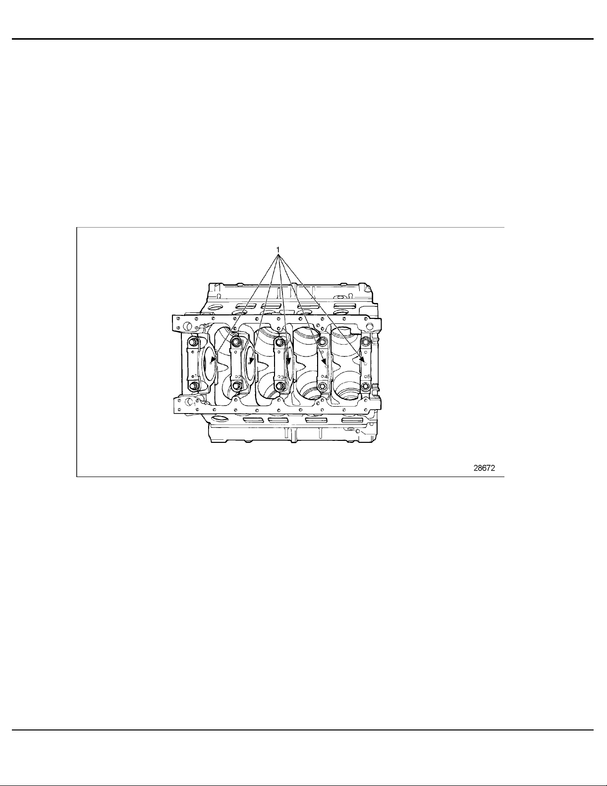
1.1 CYLINDER BLOCK
An air box conducts the air from the blowe r to the cylinders. Air box openings on each side
of the block permit piston a n d compression ring inspection through the air inlet ports in the
cylinder liners. The air box openings in the cylinder block assembly are approximately 1 7/8 in.
x 3 1/8 in. and are shielded with cast covers. For additional information on the air box drains,
Refer to section ADDITIONAL INFORMATION.
The camshaft bores are on the inner side of each cylinder bank n ear the top of the block.
The upper halves of the main bearing supports are integrally cast with the block. See Figure 1-2.
The main b earing bores are line-bored with the bearing c aps intact to ensure longitudinal
alignment. Drilled passages in the block carry the lubricating oil to all moving engine parts,
eliminating the need for external piping.
1. Location of Drilled Oil Passages
Figure 1-2 Location of Drilled Oil Passages
The top surface of each cylinder bank is grooved to accommodate a block-to-head oil seal ring.
All counterbored oil and water holes in the cylinder block use the same size seal rings.
A flange at the upper end of the cylinder liner retains each liner in the block. The liner flange rests
on an insert located in the block bore counterbore.
An individual compression gasket is used at each cylinder. When the cylinder heads are installed,
the compression gaskets form a tight seal between the heads and the cylinder block.
1-4
6SE379 0303 Copyright © 2003 DETROIT DIESEL CORPORAT ION
All information subject to change without notice.

SERIES 92 SERVICE MANUAL
1.1.1 Repair or Replacement of Cylinder Block
To determine if repair is possible or replacement is n ecessary, perform the following procedure.
SeeFigure1-3.
Figure 1-3 Flowchart for Repair or Replacement of Cylinder B lock
All information subject to change without notice.
379 0303 Copyright © 2003 DETROIT DIES EL CORPORATION
6SE
1-5

1.1 CYLINDER BLOCK
1.1.2 Removal of Cylinder Block
The hydraulically opera ted overha u l stand provides a convenient support when stripping a
cylinder block. See Figure 1-4. Once the engine is mounted in an upright position, it may be
turned on its side, rotated in either a 90 degree or 180 degree direction, locked in place, and
turned back to either end or the oil pan side up.
1. Engine Overhaul Stand
Figure 1-4 Hydraulic Engine Overhaul Stand
NOTE:
Before mounting an engine on an overhaul stand, it must be removed from its base and
disconnected from the transmission or other driven mechanism.
Details of this procedure will vary from one application to another. However, the following
steps are necessary when removing the engine:
1-6
6SE379 0303 Copyright © 2003 DETROIT DIESEL CORPORAT ION
All information subject to change without notice.

SERIES 92 SERVICE MANUAL
To avoid injury from accidental engine startup while
servicing the engine, disconnect/disable the starting
system.
1. Drain the cooling system. Refer to section 13.12.3.
2. Drain the lubricating oil. Re fer to section 13.5.2.
3. Disconnect the fuel lines. Refer to section 2.21.2.
4. Remove the air cleaner and mounting brackets. Refer to section 6.2.
5. Remove the turbocharger. Refer to section 6.6.2.
6. Disconnect the exhaust piping, and remove the exhaust manifolds. Refer to section 7.2.2.
7. Disconnect the throttle controls. Refer to section 12.17.
8. Disconnect and remove the starting motor. Refer to section 8 .2.2.
9. Disconnect and remove battery-charging alternator. 8.1.2.
10. Remove the air compressor, if used. Refer to section 10.1.
11. Remo ve the radiator. Refer to section 4.6.2.
12. Remove the fan guard. Refer to section 4.6.2.
13. Remo ve the air box drain tubes and fittings. Refer to section ADD ITIONAL
INFORMATION.
14. Remove the air box covers. Refer to section ADDI TIONAL INFORMATION.
NOTE:
Early Series 92 vehicle engines built without the air box drain check valve and engines
built with drain tubes routed to the crankcase via the dipstick adaptor should be
updated with the current open air box drain system. Refer to section ADDITIONAL
INFORMATION for inspection of the air box drains.
15. Disconnect any other lubricating oil lines, fuel lines, or electrical connections.
16. Sepa rate the e ngine from the transmission or other d rive n mechanism.
17. Remove the engine mounting bolts.
All information subject to change without notice.
379 0303 Copyright © 2003 DETROIT DIES EL CORPORATION
6SE
1-7

1.1 CYLINDER BLOCK
To avoid injury from a falling engine, an adequate lifting
device with a spreader bar and sling should be used to lift
the engine. The sling and spreader bar should be adjusted
so the lifting hooks are vertical to prevent bending the lifter
brackets. Toensure proper weightdistribution, allprovided
lifter brackets must be used.
1-8
6SE379 0303 Copyright © 2003 DETROIT DIESEL CORPORAT ION
All information subject to change without notice.

SERIES 92 SERVICE MANUAL
18. Use a spreader bar with a suitable sling and adequate chain hoist to lift the engine from
its base. See Figure 1-5.
1. Rear Engine Lifter Brackets 4. Spreader Bars
2. Lifting Sling (2) 5. Front Engine Lifter Bracket
3. Chain Hoist
Figure 1-5 Spreader Bar with Sling and Chain
All information subject to change without notice.
379 0303 Copyright © 2003 DETROIT DIES EL CORPORATION
6SE
1-9

1.1 CYLINDER BLOCK
To avoid injury from a falling engine, do not use a damaged
lifter bracket when lifting the engine.
NOTICE:
Detroit Diesel recommends replacing the former welded
brackets with the current hot stamped brackets whenever
bracket removal is required. Failure to follow these
recommendations may lead to component damage.
NOTE:
Front support brackets on 8V-92 engines are now hot-stamped to final form in one
step, eliminating the welding operation formerly r equired at the bottom outside corner
of the brackets. See Figure 1-6. Former and current design brackets are completely
interchangeable, and only the current design will be serviced. Because of the improved
engine support that results from this change, Detroit Diesel recommends replacing
the former welded brackets with the current hot-stamped brackets whenever bracket
removal is required.
Figure 1-6 Engine Front Support Bracket
1-1
0
6SE379 0303 Copyright © 2003 DETROIT DIESEL CORPORAT ION
All information subject to change without notice.

SERIES 92 SERVICE MANUAL
To avoid injury from a falling engine, ensure the engine
is securely attached to the engine overhaul stand before
releasing the lifting sling.
19. Mount the engine securely to the overhaul stand using grade 8 bolts.
NOTE:
For 6V and 8V engines, use overhaul stand J 29109 with adaptor J 33850. For 12V and
16V engines, use overhaul stand J 9389-04 and adaptor J 8650.
20. With the engine mounted on an overhaul stand, remove all of the remaining subassemblies
and parts from the cylinder block.
NOTE:
A water inlet adaptor plug and gasket replaces the rear (flywheel housing end) core hole
plug in the cylinder block air box floor on engines with an aftercooler. Refer to section 6.8.
21. Refer to section 1.1.3 for disasse mbly of the cylinder block.
1.1.3 Disassembly of Cylinder Block (12V and 16V Engines)
Disassemble 12V and 16V cylinder blocks as follows:
All information subject to change without notice.
379 0303 Copyright © 2003 DETROIT DIES EL CORPORATION
6SE
1-11

1.1 CYLINDER BLOCK
1. Remove the two "B" bolts and special washers from the oil drain back cavity.
SeeFigure1-7.
1. Spacer 3. Washer
2. Liner Bore ID
Figure 1-7 Separation of Cylinder Blocks
1-1
2
6SE379 0303 Copyright © 2003 DETROIT DIESEL CORPORAT ION
All information subject to change without notice.

SERIES 92 SERVICE MANUAL
To avoid injury from a falling e ngine, do not use a damaged
lifter bracket when lifting the engine.
2. Attach a suitable lifting bracket to the e nd of the front cylinder b lock with two 1/2 in.-13
X 2 in. bolts and two 3/8 in.-16 X 2 in. bolts. See Figure 1-8.
1. Bolts 3. Cylinder Block
2. Cylinder Block Lifting Brackets
Figure 1-8 Cylinder Block Lifting Bracket
All information subject to change without notice.
379 0303 Copyright © 2003 DETROIT DIES EL CORPORATION
6SE
1-13

1.1 CYLINDER BLOCK
To avoid injury from a falling engine, an adequate lifting
device with a spreader bar and sling should be used to lift
the engine. The sling and spreader bar should be adjusted
so the lifting hooks are vertical to prevent bending the lifter
brackets. Toensure proper weightdistribution, allprovided
lifter brackets must be used.
3. Attach a chain hoist to the lifting bracket. Lift t he cylinder blocks into a vertical position,
and rest the end of the rear cylinder block on a clean, flat surface.
4. Remove the seven remaining bolts A, C, D, and E securing the two cylinder blocks
together. See Figure 1 -7.
5. Remove the two spacers used o n the two "D" bolts. See Figure 1-7.
1-1
4
6SE379 0303 Copyright © 2003 DETROIT DIESEL CORPORAT ION
All information subject to change without notice.

SERIES 92 SERVICE MANUAL
6. Lif t the front cylinder block off the rear cylinder block, and remove the seal strip from the
groove in the rear block.
NOTE:
On aftercooled engines, it will be necessary to remove the 2 1/2 in. p lug in the rear core
holeinthebottomoftheairboxandthe21/4in.pluginthetopdeckoftheblockinfront
of the blower mounting pad. See Figure 1-9.
1. Rear Water Inlet Adaptor Plug 2 1/2 in. 2. Front Water Inlet Adaptor Plug 2 1/4 in.
Figure 1-9 Location of Front and Rear Air Box Cup Plugs
7. Ref er to section 1.1.4 for cleaning of the cylinder block.
1.1.4 Cleaning of Cylinder Block
Prior to inspection, thoroughly clean the cylinder block as follows:
All information subject to change without notice.
379 0303 Copyright © 2003 DETROIT DIES EL CORPORATION
6SE
1-15

1.1 CYLINDER BLOCK
1. Scrape a ll gasket material from the cylinder block.
2. Remove all oil gallery plugs and core hole plugs ( except the cup plugs) to allow the
cleaning solution to contact the inside of the oil and water passages.
NOTE:
If a core hole plug is difficult to remove, hold a 3/4 in. drift against the plug. Give it a
few sharp blows with a one pound hammer. With a 1/2 in. flexible handle and a short
extension placed in the plug countersink hole, turn the plug slightly to tighten. Turn it in
the opposite direction, and back the plug out.
To avoid injury from improper use of chemicals, follow the
chemical manufacturer’s usage, handling, and disposal
instructions. Observe all manufacturer’s cautions.
3. Agitate the cylinder block in a hot bath of commercial h eavy- duty alkaline cleaner
solution to remove grease.
To avoid injury from improper use of chemicals, follow the
chemical manufacturer’s usage, handling, and disposal
instructions. Observe all manufacturer’s cautions.
4. Rinse the block in hot water, or steam clean it to remove the alkaline cleaner solution.
5. If the water jackets are heavily scaled, proceed as follows:
[a] Agitate the block in a bath of inhibited phosphoric acid.
[b] Allow the block to remain in the ac id bath until the bubbling stops (approximately
30 minutes).
[c] Lift the block, drain it, a nd immerse it in the same acid solution for 10 minutes.
[d] Repeat step 5[c] until all scale is removed.
[e] Rinse the block in clean hot water to remove the acid solution.
1-1
6
6SE379 0303 Copyright © 2003 DETROIT DIESEL CORPORAT ION
All information subject to change without notice.

SERIES 92 SERVICE MANUAL
To avoid injury from improper use of chemicals, follow the
chemical manufacturer’s usage, handling, and disposal
instructions. Observe all manufacturer’s cautions.
[f] Immerse the b lock in an alkaline bath to neutralize any acid remaining on the casting.
[g] Wash the block in clean wa ter, or steam clean it.
To avoid injury from flying debris when using compressed
air, wear adequate eye protection (face shield or safety
goggles) and do not exceed 40 psi (276 kPa) air pressure.
6. Dry the cylinder block with compressed air.
7. Thor oughly clean all water passages, oil galleries, and air box drain openings.
To avoid injury from contact with the contaminants in used
engine oil, wear protective gloves and apron.
8. Coat the air box core plug threads and the gaskets with clean engine oil.
9. Clean the cup plug holes, and apply Loctite 567 pipe sealant with Teflon, or equivalent, to
the outer diameter of the plugs.
10. Refer to section 1.1.4.3 for inspection of cylinder block.
1.1.4.1 Pressure Test Cylinder Block (Immersion Method)
Use t his method when a large water tank is available and the cylinder b lock is completely
stripped of all parts.
1. Make a steel plate of 1/2 in. stock to cover each cylinder bank of the block. The plates will
adequately seal the top surface of the block whe n use d with new cylinder line compression
gaskets a nd water hole seal rings.
2. Use water hole cover plates and gaskets to seal the water openings in the sides of the
block. One cover plate should be drilled and tapped to provide a connection for an air line
to pressurize the water jackets.
3. The seal ring grooves in the cylinder bores must be clean. Install new seal rings in the
grooves a bove the air inlet ports.
All information subject to change without notice.
379 0303 Copyright © 2003 DETROIT DIES EL CORPORATION
6SE
1-17

1.1 CYLINDER BLOCK
To avoid injury from contact with the contaminants in used
engine oil, wear protective gloves and apron.
4. Apply clean engine oil to the seal rings.
NOTICE:
Install the inner inserts with care to prevent the seal rings from
being rolled or damaged.
5. Place liner inserts in the cylinder block counterbores. Slide the cylinder liners into the
block.
6. Install new compre ssion gaskets and water hole seal rings in the block counterbores.
7. Secure the plates to the block with 11/16 in.-11 bolts and flat washers. Tighten the bolts
to 330-352 N·m (250-260 lb·ft) torque.
8. Bolt steel plates and suitable rubber gaskets to the water inlet and outlet holes, making
them airtight.
9. Drill and tap one cover plate to provide a connection for an air line.
10. Seal the aftercooler water inlet adaptor plug in the air box floor.
11. Immerse the block for 20 minutes in a tank of water heat ed to 82
-93 C (180 -200 F).
To avoid injury from flying debris when using compressed
air, wear adequate eye protection (face shield or safety
goggles) and do not exceed 40 psi ( 276 kPa) air pressure.
12. Apply 276 kPa (40 lb/in.2) air pressure to the water jackets.
13. Visually inspect for bubbles indicating cracks in the block.
[a] If cracks are detected, replace the block. Refer to section 1.1.6 and
refertosection1.1.7.
[b] If no cracks are detected, proceed with inspection.
14. After completing the pressure test, remove the block from the water tank.
1-1
8
6SE379 0303 Copyright © 2003 DETROIT DIESEL CORPORAT ION
All information subject to change without notice.

SERIES 92 SERVICE MANUAL
To avoid injury from flying debris when using compressed
air, wear adequate eye protection (face shield or safety
goggles) and do not exceed 40 psi (276 kPa) air pressure.
15. Remove the plates, gaskets, liners, and inserts. Blow out all passages in the block with
compressed air.
To avoid injury from flying debris when using compressed
air, wear adequate eye protection (face shield or safety
goggles) and do not exceed 40 psi (276 kPa) air pressure.
16. Dry the cylinder liners and inserts with compressed air, and coat them with oil to prevent
rust.
17. Ref er to section 1.1.5 for assembly procedure.
1.1.4.2 Pressure Test Cylinder Block (Leak-Marker)
Use this method when a large water tank is unavailable or when the block is not completely
stripped.
The following must be removed before performing this test:
Cylinder heads, refer to section 1.3.
Blower, refer to section 6.5.
Oil cooler, refer to section 3.7.
Air box covers, refer to section ADDITIONAL INFORMATION.
Oil pan, refer to section 3.11.
Perform t he following to pressure test:
1. Make a steel plate of 1/2 in. stock to cover each cylinder bank of the block. The plates will
adequately seal the top surface of the block whe n use d with new cylinder line compression
gaskets a nd water hole seal rings.
2. Use water hole cover plates and gaskets to seal the water openings in the sides of the
block. One cover plate should be drilled and tapped to provide a connection for an air line
to pressurize the water jackets.
All information subject to change without notice.
379 0303 Copyright © 2003 DETROIT DIES EL CORPORATION
6SE
1-19

1.1 CYLINDER BLOCK
NOTICE:
Do not use methoxypropanol- based antifreeze. It will destroy
the water seals.
To avoid injury from improper use of chemicals, follow the
chemical manufacturer’s usage, handling, and disposal
instructions. Observe all manufacturer’s cautions.
3. Before attaching the last sealing plate, fill the water jacket with a mixture of water and one
gallon ethylene glycol based antifreeze. The ant ifreeze will penetrate small cracks, and its
color w ill mark their presence.
4. Install the remaining sealing plate, and tighten securely.
To avoid injury from flying debris when using compressed
air, wear adequate eye protection (face shield or safety
goggles) and do not exceed 40 psi ( 276 kPa) air pressure.
5. Apply 276 kPa (40 lb/in.2) air pressure to the water jacket. Maintain this pressure for at
least two hours to give the water and antifreeze mixture ample time to work its way
through any cracks.
6. Visually inspect cylinder bores, air box, oil passages, crankcase, and block exterior.
[a] If the water and antifreeze mixture is visible, the block is cracked and must be
replaced. Refer to section 1.1.5.
[b] If no water and antifreeze mixture is visible, proceed with block inspection.
7. Remove the plates, and drain the w ater jacket.
8. Remove the liners and seal rings.
To avoid injury from flying debris when using compressed
air, wear adequate eye protection (face shield or safety
goggles) and do not exceed 40 psi ( 276 kPa) air pressure.
9. Blow out all of the pas sages in the block with compre ssed air.
1-2
0
6SE379 0303 Copyright © 2003 DETROIT DIESEL CORPORAT ION
All information subject to change without notice.

SERIES 92 SERVICE MANUAL
To avoid injury from flying debris when using compressed
air, wear adequate eye protection (face shield or safety
goggles) and do not exceed 40 psi (276 kPa) air pressure.
10. Dry the cylinder liners and inserts with compressed air, and coat them with oil to prevent
rust. Refer to section 1.1.5.
1.1.4.3 Inspection of Cylinder Block
Inspect the cylinder block as follow s:
1. Visually inspect all machined surfac es for nicks or burrs.
[a] If surfaces are nicked or burred, smooth them with a stone.
[b] If surfaces are free of nicks and burrs, proceed with inspection.
2. Visually inspect tapped holes for thread damage.
[a] If threads are damaged, re- tap the holes or install helical thread inserts.
NOTE:
An insert block thread repair kit J 29513 is now available for installing an 11/16 in.-11
helicoil thread insert in the cylinder head retaining bolt holes and the main bearing cap
retaining bolt holes of the cylinder block.
[b] If threads are cracked, replace block.
[c] If t hre ads are undamaged, proceed with inspection.
3. Visually inspect the block for loose or damaged dowel pins.
[a] If dowel pins are loose, tighten them.
[b] If dowel pins are damaged, replace them.
[c] If dowel pins are neither loose or damaged, proceed with inspection.
All information subject to change without notice.
379 0303 Copyright © 2003 DETROIT DIES EL CORPORATION
6SE
1-21

1.1 CYLINDER BLOCK
4. Measure dowel extension from the ends of the cylinder block. See Figure 1-10.
1. Measure Dowel Extension Here
Figure 1-10 Measuring Dowel Extension
[a] If on 6V and 8V engines, dowels do not extend 16.00 mm (0.630 in.) from the ends
of the cylinder block , the dowels m ust be replaced.
[b] If on 12V and 16V engines, dowels do not extend 22.35 mm (0.880 in.) from ends of
the cylinder block, the dowels must be re placed.
[c] If dowels extend the appropriate distance from the cylinder block, proceed with
inspection.
1-2
2
6SE379 0303 Copyright © 2003 DETROIT DIESEL CORPORAT ION
All information subject to change without notice.

SERIES 92 SERVICE MANUAL
5. Me asure the extension o f the dowels used to retain the crankshaft thrust washers from
the bearing cap surface. S ee Figure 1-11.
Figure 1-11 Measurement of Bearing Cap Thrust Washer Dowel Extension
[a] If the dowels do not extend 2.79-3.05 mm (0.110-0.120 in.) from the sur fac e of the
bearing ca p, the dowels must be replaced.
[b] If the dowels extend the appropriate distance fr om the bearing cap surface, proceed
with inspection.
6. I n spect the dowe l pins in the rear main bearing cap for looseness or damage.
[a] If pins are loose or damaged, they must be replaced.
NOTE:
Stepped dowel pins are used to replace damaged or loose pins. Prior to installation,
the holes in the bearing cap must be bored with a No. 11-4.851 mm (0.1910 in.) or No.
12-4.801 mm (0.1890 in.) drill.
[b] If pins are neither loose or dam aged, proceed with inspection.
All information subject to change without notice.
379 0303 Copyright © 2003 DETROIT DIES EL CORPORATION
6SE
1-23

1.1 CYLINDER BLOCK
7. Using a straight edge and feeler gage , check t he cylinder block head c ontact surfaces for
flatness. See Figure 1-12.
1. Feeler Gage
Figure 1-12 Measurement of Cylinder Block Head Contact Surfaces
[a] On 6V and 12V engines, if the cylinder head deck surfaces vary more than 0.08 mm
(0.003 in.) transversely, and 0.15 mm (0.006) longitudinally, the block must be
replaced. Refe r to section 1.1.5 and refer to section 1.1.6.
[b] On 8V and 16V engines, if the cylinder head deck surfaces vary more than 0.08 mm
(0.003 in.) transversely, and 0.18 mm (0.007 in.) longitudinally, the block must be
replaced. Refe r to section 1.1.5 and refer to section 1.1.6.
[c] If measurements fall within specifications, proceed with inspection.
8. Measure the distance from the centerline of the crankshaft to the top of the cylinder
head surface.
[a] If the distance is less than 411.07 mm (16.184 in.) or more than 411.20 mm (16.189
in.), replace the block. R efer to section 1.1.5 and refer to section 1.1.6.
[b] If the measurement falls within specifications, proceed with inspection.
1-2
4
6SE379 0303 Copyright © 2003 DETROIT DIESEL CORPORAT ION
All information subject to change without notice.

SERIES 92 SERVICE MANUAL
9. Clean the c ounterbor e and che ck counterbore depth. See Figure 1-13.
Figure 1-13 Measurement of Cylinder Liner Counter Bores
[a] If the measurement does not fall between 12.078 mm (0.4755 in.) and 12.116 mm
(0.4770 in.) and varies more than 0.038 mm (0.0015 in.) throughout the
entire circumference, r eplace the cylinder block. Refer to section 1.1.5 and
refer to section 1.1.6.
[b] If there is over a 0.038 mm (0.0015 in.) difference between a ny two adjacent cylinder
counterbores, when measured along the cylinder longitudinal centerline, the cylinder
block must be replaced. Refer to section 1.1.5 and refer to section 1.1.6.
[c] If the c ounterbore measurements are within specifications, proceed with inspection.
10. I nspect the cylinder head retaining bolt holes for damaged threads.
[a] If the threads are damaged, use a tap to "clean-up" the threads. If necessary, install a
helical thread insert. Refer to section 1.1.4.4 for inspection of the main bearing bore.
[b] If threads are undamaged, p roceed with inspection. Refer to section 1.1.4.4 for
inspection of the main bearing bore.
1.1.4.4 Inspection of Main Bearing Bore
Inspect the ma in bea ring bores as follows:
1. Check the main bearing bore diameter. The specified bore diameter is 122.22-122.25 mm
(4.812-4.813 in.).
All information subject to change without notice.
379 0303 Copyright © 2003 DETROIT DIES EL CORPORATION
6SE
1-25

1.1 CYLINDER BLOCK
[a] If the diameters for each bore does not fall within these limits, the cylinder block
must be replaced. Refer to section 1.1.6 and refer to section 1.1.7.
[b] If the diameter for ea ch bore falls within these limits, proceed with inspection.
NOTE:
At the time of major engineoverhaul, the cylinder block mainbearingbore measurements
should be made with the block in an upside down position on the floor rather than on an
engine overhaul stand.
2. Check the main bearing bores for misalignment.
[a] If bores are misaligned more than 0.03 mm (0.001 in.) overall, or 0.013 mm
0(.0005 in.) between adjacent bores, the block must be line-bored or discarded.
Refer to section ADDITIONAL INFORMATI ON for line boring proc edure and
refer to section 1.1.4.5 to continue inspection.
[b] If bores are aligned, proceed with inspection, refer to section 1.1.4.5.
1.1.4.5 Inspection of Block Bore
Inspect t he block bores as follows:
1-2
6
6SE379 0303 Copyright © 2003 DETROIT DIESEL CORPORAT ION
All information subject to change without notice.

SERIES 92 SERVICE MANUAL
NOTICE:
Cylinder block bore measurements should be made with the
block flat on the floor. The main bearing caps should be in
place, and the bolts torqued to 312-325 N·m (230-240 lb·ft).
Failure to follow the torque specifications may result in damage
to the cylinder block.
1. Measure each cylinder bore on a 90 de gree axis using cylinder bore gage J 5347-B.
See Figure 1-14.
Figure 1-14 Measurement of Cylinder Block Bore
NOTE:
Dial bore gage setting master tool J 23059-01 may be used for setting the cylinder
bore gage.
All information subject to change without notice.
379 0303 Copyright © 2003 DETROIT DIES EL CORPORATION
6SE
1-27

1.1 CYLINDER BLOCK
[a] At position A, diameter m ust not exceed 136.195 mm (5.3620 in.), if new, or 136.233
mm (5.3635 in.), if used.
[b] At position B, diameter must not excee d 135.598 mm (5.3385 in.), if new, or 135.623
mm (5.3395 in.) if used.
[c] At position C, diameter must not exceed 132.524 mm (5.2175 in.), if new, or 132.550
mm (5.2185 in.), if used.
[d] At position D, diameter must not exceed 132.537 mm (5.2180 in.) if new, or 132.550
mm (5.2185 in.), if used.
[e] If measurements d o not fall within specifications, replace the block.
Refertosection1.1.5.
[f] If measure ments fall within specifications, proceed with block bore inspection.
2. Measure the taper and out-of-roundness.
[a] If the taper and out-of-roundness exceeds 0.025 mm (0.0010 in.), the block must be
replaced. Refer to section 1.1.5.
[b] If the taper and out-of-roundness falls within specifications, proceed with inspection.
3. Clean and inspect the seal ring grooves in the cylinder block bores.
[a] If grooves and lands are pitted or eroded, or if the grooves above the air inlet ports
are excessively eroded, replace the block. Refer to section 1.1.5.
[b] If grooves and lands are neither pitted nor eroded, refer to section 1.1.4.1 or
refer to section 1.1.4.2 for pressure test.
1.1.5 Assembly of Cylinder Block (12V and 16V Engines)
Assemble the 12V and 16V engine as follows:
To avoid injury from flying debris when using compressed
air, wear adequate eye protection (face shield or safety
goggles) and do not exceed 40 psi ( 276 kPa) air pressure.
NOTE:
Before a reconditioned or a new service replacement cylinder block is used, steam clean
to remove all traces of oil or rust preventive. Blow out the galleries with compressed air.
1-2
8
6SE379 0303 Copyright © 2003 DETROIT DIESEL CORPORAT ION
All information subject to change without notice.

SERIES 92 SERVICE MANUAL
To avoid injury from a falling engine, an adequate lifting
device with a spreader bar and sling should be used to lift
the engine. The sling and spreader bar should be adjusted
so the lifting hooks are vertical to prevent bending the lifter
brackets. Toensure proper weightdistribution, all provided
lifter brackets must be used.
For assembly of the 6V and 8V engine refer to section 1.1.6.
1. Lift the cylinder block assembly with a chain hoist. Place the cylinder block on a clean,
flat surface with the seal strip groove in the front end facing up.
®
2. Apply a thin coat of Lubriplate
, or equivalent, in the seal strip and seal ring grooves.
Place a new seal strip in the groove.
3. Plac e two new seal rings in the seal ring grooves.
4. Plac e one new seal ring in the main oil gallery seal ring groove. The seal strip must lay
flat in the groove.
5. Apply a thin coat of Lubriplate, o r equivalent, on the exposed flat surface of the seal strip.
Remove any excess Lubriplate from the cylinder block.
To avoid injury from a falling engine, ensure the engine
is securely attached to the engine overhaul stand before
releasing the lifting sling.
6. Mount the cylinder block on the overhaul stand.
7. I f a new service replacement block is used:
Stamp the engine serial number and model number on the right-hand side of the
cylinder block.
Stamp the position num ber on the main bearing caps.
Stamp the No. 1 bearing position on the oil pan mounting flange.
8. Use a suitable non-hardening sealant on the thr eads of the plugs and drain cocks.
9. I nstall all of the required cylinder block plugs and drain co cks.
NOTE:
Effective with engines built from and after February 16, 1998, the 1 in. diameter holes in
the front left-bank of 6V, 8V, 12V, and 16V cylinder blocks have been eliminated. This
area is now cast solid to provide enhanced coolant flow to the u pper cylinder areas of
the engine. On blocks built prior to the foregoing date, the 1 in. diameter cup plugs
used to seal this area have been or should be replaced by 1-1/4 in. long solid rubber
service plugs. When properly installed, the solid plugs provide an inside coolant passage
All information subject to change without notice.
379 0303 Copyright © 2003 DETROIT DIES EL CORPORATION
6SE
1-29

1.1 CYLINDER BLOCK
configuration similar to that in the improved blocks, resulting in enhanced upper cylinder
cooling. For this reason, only the solid plugs should be installed in this area when
assembling or servicing former blocks. Cup plugs should no linger be used. Apply
Loctite 620 or equivalent anaerobic sealant to the O.D. of the plugs, then install plugs in
the block until they bottom in the holes. R efer to section ADDITIONAL INFORMATION
for installation of new block plugs and cylinder block plugging instructions.
10. Install the necessary plugs and dowels. Refer to section ADDITIONAL I NFORMATION,
cylinder block plugging instructions.
11. Install and tighten the 2 1/2 in.-16 plugs to 312-366 N·m (230-270 lb·ft) torque using plug
installer J 23019.
12. Install the plugs flush with or below the surface of the block.
NOTE:
The plug, that blocks the oil cooler adaptor inlet from the adaptor outlet, must be installed
in the vertical passage.
13. Install subassemblies and parts on the block.
To avoid injury from a falling engine, an adequate lifting
device with a spreader bar and sling should be used to lift
the engine. The sling and spreader bar should be adjusted
so the lifting hooks are vertical to prevent bending the lifter
brackets. Toensure proper weightdistribution, allprovided
lifter brackets must be used.
14. Use a chain hoist and suitable sling to transfer the engine to a dynamometer test stand.
15. Dismount the block from the lifting device.
16. Run the dynamometer test. Refer to section 11.6 for run-in procedures.
17. Lift the cylinder block approximately four feet off the floor to position the front cylinder
block over the rear cylinder block, hor izontally and parallel.
NOTICE:
Do not slide the faces against each other. This may dislodge or
twist the block seal strip or oil gallery seal ring.
18. Lower the fr ont block against the rear block. Position the front cylinder block as close to
the final alignment as possible before lowering it on the rear cylinder block.
19. Place a suitable wooden block, approximately 3 in. thick, across the number 7 (12V), or
8 (16V), main bear ing cap as a support for the alignment tool.
1-3
0
6SE379 0303 Copyright © 2003 DETROIT DIESEL CORPORAT ION
All information subject to change without notice.

SERIES 92 SERVICE MANUAL
20. Plac e the triangular cylinder block alignment tool J 21799 in the main bearing bore.
See Figure 1-15 for contact point locations. R est the lower end of the tool on the wood
block.
1. Seal Ring 3. Seal Ring
2. Special Plug
Figure 1-15 Position of Cylinder Block Alignment Tool
21. I nstall the number 4, 5, and 6 (12V), or 5, 6, and 7 (16V), crankshaft main bearing caps in
their original positions. Tighten the bolts to 312-325 N·m (230-240 lb·ft) torque.
22. Lubricate the threads and the contact face of the cylinder block attaching bolts A, C, D,
and E with a small amount of International Compound No. 2, or equivalent.
All information subject to change without notice.
379 0303 Copyright © 2003 DETROIT DIES EL CORPORATION
6SE
1-31

1.1 CYLINDER BLOCK
23. Place a spacer on each "D" bolt, as shown in inset "D". See Figure 1-16.
1. Spacer 3. Washer
2. Liner Bore ID
Figure 1-16 Separation of Cylinder Liner Blocks
NOTE:
Do not tighten the bolts at this time.
24. If it is necessary to shift the front cylinder block when installing the attaching bolts, use a
soft hammer to tap at points "A" and "B". See Figure 1-16.
25. Move a dial indicator across the bottom faces (oil pan rail) of the c y linder blocks. The
mismatch, if any, between the bottom faces of the two blocks must be equal on both sides
of the cylinder block assembly within 0.05 mm (0.002 in.).
26. If it is necessary to shift the front c y linder block when checking the alignment, tap at
points "A" and "B" with a soft hammer to align the blocks.
1-3
2
6SE379 0303 Copyright © 2003 DETROIT DIESEL CORPORAT ION
All information subject to change without notice.

SERIES 92 SERVICE MANUAL
27. Tighten the four "C" and "D" bolts to 217- 231 N·m (160-170 lb·ft) torque.
28. Tighten the two "E" bolts to 217-231 N·m (160-170 lb·ft) torque.
29. Tighten the "A" bolt nut to 224-238 N·m ( 160-175 lb·ft) torque.
30. Repeat the cylinder block alignment check. If the alignment is unsatisfactory, loosen all of
the attaching bolts, realign the blocks, and retighten the attaching bolts.
31. When cylinder block is aligned, cut the excess block seal strip lengths flush with the
bottom face of the block.
32. Remove the cylinder block alignment tool J 21799 and the wood block.
To avoid injury from a falling engine, an adequate lifting
device with a spreader bar and sling should be used to lift
the engine. The sling and spreader bar should be adjusted
so the lifting hooks are vertical to prevent bending the lifter
brackets. Toensure proper weightdistribution, all provided
lifter brackets must be used.
33. Lif t the cylinder block a ssem bly with a chain hoist, and place it horizontally on a clean,
flat surface.
34. In stall the "B" bolts and washer s. Use power universal socket J 25451-4A and hex bit
J 25451-5 from set J 25451-B.
NOTICE:
Do notusesocket J 25451-4A fromset J 25451-B whentorquing
these bolts. Damage to the socket could occur.
35. Tighten bolts to 325-339 N·m (240-250 lb·ft) torque, using wrench J 25451-7 from set
J 25451-B. Refer to section 1.1.7 for installation of engine.
1.1.6 Assembly of Cylinder Block (6V and 8V Engines)
Assemble 6V and 8V engines as follows:
All information subject to change without notice.
379 0303 Copyright © 2003 DETROIT DIES EL CORPORATION
6SE
1-33

1.1 CYLINDER BLOCK
To avoid injury from improper use of chemicals, follow the
chemical manufacturer’s usage, handling, and disposal
instructions. Observe all manufacturer’s cautions.
To avoid injury from flying debris when using compressed
air, wear adequate eye protection (face shield or safety
goggles) and do not exceed 40 psi ( 276 kPa) air pressure.
NOTE:
Before a reconditioned or a new service replacement cylinder block is used, steam clean
to remove all traces of oil or rust preventive. Blow out the galleries with compressed air.
To avoid injury from a falling engine, ensure the engine
is securely attached to the engine overhaul stand before
releasing the lifting sling.
1. Mount the cylinder block on the overhaul stand.
2. If a new service replacement block is used:
Stamp the engine serial number and model number on the right-hand side of the
cylinder block.
Stamp the position number on the main bearing caps.
Stamp the No. 1 bearing position on the oil pan mounting flange.
3. Use a suitable non-hardening sealant on the surface of the bloc k.
4. Install all of the required cylinder block plugs and drain cocks.
NOTE:
Effective with engines built from and after February 16, 1998, the 1 in. diameter holes in
the front left-bank of 6V, 8V, 12V, and 16V cylinder blocks have been eliminated. This
area is now cast solid to provide enhanced coolant flow to the upper cylinder areas of
the engine. On blocks built prior to the foregoing date, the 1 in. diameter cup plugs
used to seal this area have been or should be replaced by 1-1/4 in. long solid rubber
service plugs. When properly installed, the solid plugs provide an inside coolant passage
configuration similar to that in the improved blocks, resulting in enhanced upper cylinder
cooling. For this reason, only the solid plugs should be installed in this area when
assembling or servicing former blocks. Cup plugs should no linger be used. Apply
Loctite 620 or equivalent anaerobic sealant to the O.D. of the plugs, then install plugs in
1-3
4
6SE379 0303 Copyright © 2003 DETROIT DIESEL CORPORAT ION
All information subject to change without notice.

SERIES 92 SERVICE MANUAL
the block until they bottom in the holes. Refer to section ADDITIONAL INFORMATION
for installation of new block plugs and cylinder block plugging instructions.
5. I nstall the necessary plugs and dowels. Refer to section ADDITIONAL INFORMATION,
cylinder block plugging instructions.
6. Use a suitable non-hardening sealant on the thr eads of the plugs and drain cocks.
7. I nstall the plugs flush with or below the surfaces of the block.
NOTE:
The plug, that blocks the oil cooler adaptor inlet from the adaptor outlet, must be installed
in the vertical passage.
8. U se tool J 33420 to install the 1 in. plug in the oil ga llery to a 86.4 mm (3.40 in.) depth.
9. Use tool J 34650 to install the sealant-coated 1/8 in.-27 pipe plugs.
10. I nstall a stepped dowel pin to replace loose pins in the rear main bearing cap.
11. Remove all burrs from the base of the dowel pins to ensure proper seating of the thrust
washers.
12. Install assemblies and parts.
To avoid injury from a falling engine, an adequate lifting
device with a spreader bar and sling should be used to lift
the engine. The sling and spreader bar should be adjusted
so the lifting hooks are vertical to prevent bending the lifter
brackets. Toensure proper weightdistribution, all provided
lifter brackets must be used.
13. Use a chain hoist and suitable sling to transfer the engine to a dynamometer test stand.
Refer to section 11.6 for run-in procedures.
To avoid injury from a falling engine, ensure the engine
is securely attached to the engine overhaul stand before
releasing the lifting sling.
14. Dismount the block from the lifting device.
15. U se the dynamometer to run the engine.
16. Run the dynamometer test. Refer to section 1.1.7 for installation of engine.
All information subject to change without notice.
379 0303 Copyright © 2003 DETROIT DIES EL CORPORATION
6SE
1-35

1.1 CYLINDER BLOCK
1.1.7 Installation of Engine
Install the engine a s follows:
To avoid injury from a falling engine, an adequate lifting
device with a spreader bar and sling should be used to lift
the engine. The sling and spreader bar should be adjusted
so the lifting hooks are vertical to prevent bending the lifter
brackets. Toensure proper weightdistribution, allprovided
lifter brackets must be used.
1. Use a spre ade r bar with a suitable sling and adequate chain hoist to replace the engine in
its base.
2. Replace the engine mounting bolts.
3. Connect the engine to the transmission or other driven mechanisms.
4. Connect lubricating oil lines.
5. Connect the fuel lines.
6. Connect the electrical connections.
7. Attach the air box covers. R efer to section ADDITIONAL I NFORMATION.
NOTE:
DDC recommends retrofitting existing 6V inline coach engines with the new
air box covers and drains because of the significant drainage improvement.
Refer to section ADDITIONAL INFORMATION.
NOTE:
To ensure efficient air box drainage, install air box covers with the drilled drain
openings down and the slot in the large cover facing inboard. Install check valves
at an angle of 30 degrees to 45 degrees. Do not install check valves horizontally.
Refer to section ADDITIONAL INFORMATION.
8. Attach the air box drain tubes and fittings. Refer to section ADDITIONAL
INFORMATION .
9. Attach theradiator, fanguard, and otherrelated cooling systemparts. Refer tosection 4.6.3.
10. Attach the air compressor, if used. Refer to section 10.1.
11. Connect the starting motor, battery-charging alternator, and other related electrical system
parts. Refer to section 8.1.3 and refer to se ction 8.2.3.
12. Connect the throttle controls.
13. Connect the exhaust piping, and the exhaust manifolds. Refer to section 7.2.3.
1-3
6
6SE379 0303 Copyright © 2003 DETROIT DIESEL CORPORAT ION
All information subject to change without notice.

SERIES 92 SERVICE MANUAL
14. I nstall the turbocharger, if used. Refer to section 6.6.5.
15. R epla ce the air cleaner and mounting brackets. Refer to section 6.2.3.
16. Connec t the fuel lines. Refer to section 2.21.5.
17. Fill lubricating system with the recom m ended grade of oil and viscosity.
Refer to section 5.2 and refer to section 13.5.1.
18. Fill the cooling system with the specified antifreeze. Refer to section 5.3 and
refer to section 13.12.2.
19. Refer to section 11.6 for the run-in procedures.
All information subject to change without notice.
379 0303 Copyright © 2003 DETROIT DIES EL CORPORATION
6SE
1-37

1.2 CYLINDER BLOCK END PLATES
1.2 CYLINDER BLOCK END PLATES
Flat steel plates bolted to each end of the cylinder block provide a support for the flywheel
housing at the rear and a balance we ight cover at the front of the engine. S ee Figure 1- 17. The
rear end plate has a 3 in. diameter breather hole for crankcase ventilation. Gaskets are used
between the block and each end plate. On current engines, the left-bank accessory drive mounting
hole in the rear end plate is omitted, unless an accessory drive is specified.
1. Rear End Plate 4. Front End Plate Gasket
2. Rear End Plate Gasket 5. Front End Plate
3. Cylinder Block
Figure 1-17 Cylinder Block Front and Rear End Plates (8V Engine)
1-3
8
6SE379 0303 Copyright © 2003 DETROIT DIESEL CORPORAT ION
All information subject to change without notice.

SERIES 92 SERVICE MANUAL
1.2.1 Repair or Replacement of Cylinder Block End Plate
To determine if repair is possible or replacement is n ecessary, perform the following procedure.
See Figure 1-18.
Figure 1-18 Flowchart for Repair or Replacement of Cylinder Block
End Plates
All information subject to change without notice.
379 0303 Copyright © 2003 DETROIT DIES EL CORPORATION
6SE
1-39

1.2 CYLINDER BLOCK END PLATES
1.2.2 Removal of Cylinder Block Rear End Plate
Remove the cylinder block rear end plates as follows:
1. Remove the 5/8 in.-11 x 1 in. bolt on the right rear side of the rear end plate.
SeeFigure1-19.
1. Rear End Plate 4. Rear End Plate Gasket
2. Rear End Plate Bolt 5. Cylinder Block
3. Washer
Figure 1-19 Cylinder Block Rear End Plate
2. Remove the bolts and lock washers retaining the rear end plate to the cylinder block.
3. Remove and discard gaskets. Refer to section 1.2.3.
1-4
0
6SE379 0303 Copyright © 2003 DETROIT DIESEL CORPORAT ION
All information subject to change without notice.

SERIES 92 SERVICE MANUAL
1.2.3 Removal of Cylinder Block Front End Plate
Remove the front end plate as follows:
1. Remo ve the bolts and lock washers retaining the front end plate to the cylinder block.
See Figure 1-20.
1. Front End Plate Bolt 4. Front End Plate Gasket
2. Front End Plate 5. Cylinder Block
3. Small Round Gasket 6. Lock Washer
Figure 1-20 Cylinder Block Front End Plate
2. Removeanddiscardthegaskets.Refertosection1.2.3.1.
3. Refer to s e ction 1.2.3.1 for cleaning of cylinder block end plate.
All information subject to change without notice.
379 0303 Copyright © 2003 DETROIT DIES EL CORPORATION
6SE
1-41

1.2 CYLINDER BLOCK END PLATES
1.2.3.1 Cleaning of Cylinder Block End Plate
Prior to inspection, clean the end plates as follows:
1. All of the old gasket m aterial must be removed from both surfaces of the end plate and
the c ylinder block.
To avoid injury from improper use of chemicals, follow the
chemical manufacturer’s usage, handling, and disposal
instructions. Observe all manufacturer’s cautions.
2. Immerse the end pla tes in a hot bath of commercial heavy-duty alkaline cleaner solution.
To avoid injury from improper use of chemicals, follow the
chemical manufacturer’s usage, handling, and disposal
instructions. Observe all manufacturer’s cautions.
3. Rinse them in hot water, or steam clean to remove the alkaline cleaner solution.
4. Refer to section 1.2.3.2 for inspection of cylinder block end plate.
1.2.3.2 Inspection of Cylinder Block End Plate
Inspect the cylinder block end plates as follows:
1. Inspect both surfaces of each end plate for n icks, dents, scratch es, or score marks.
[a] If nicked, dented, scratched, or scored, clean with crocus cloth.
[b] If excessively nicked, dented, scratched, or scored, replace the end plates.
Refertosection1.2.4.
[c] If the end plates are not nicked, dented, scratched, or scored, proceed with inspection.
2. Check the end plates for warpage.
[a] If w arped, replace the end plates. Refer to section 1.2.4.
[b] If t he end plates a re not warped, proceed with inspection.
3. Check the plug nuts in the end plates for crack s or da m aged threads.
[a] If cracked or threads are damaged, replace the plug nuts. Refer to section 1.2.4 to
continue installation.
1-4
[b] If not cracked or d amage d, reuse the p lug nuts. Refer to section 1.2.4 for installation
of cylinder block front end plate.
2
6SE379 0303 Copyright © 2003 DETROIT DIESEL CORPORAT ION
All information subject to change without notice.

SERIES 92 SERVICE MANUAL
1.2.4 Installation of Cylinder Block Front End Plate
Install the front end plate as follows:
1. Affix new gaskets to the ends of the cylinder block. Attach the small round gasket to the
corner at the f ront end of the cylinder block. See Figure 1-21.
1. Front End Plate Bolt 4. Front End Plate Gasket
2. Front End Plate 5. Cylinder Block
3. Small Round Gasket 6. Lock Washer
Figure 1-21 Cylinder Block Front End Plate
2. Attach the front end plate to the cylinder block with bolts and lock washers. Finger-tighten
the bolts.
All information subject to change without notice.
379 0303 Copyright © 2003 DETROIT DIES EL CORPORATION
6SE
1-43

1.2 CYLINDER BLOCK END PLATES
3. Insert the right-bank camshaft end bearing through the SMALL bearing bore in the end
plate and into the block bore to accurately align the end plate with the cylinder block.
NOTE:
The holes in the front and rear end plates for the camshaft end bearings are not the
same size. The smaller hole is accurately machined for alignment purposes and is
always located on the right side of the engine, as viewed from the rear.
4. With the bearing in place, tighten the 1/2 in.-13 end plate-to-cylinder block bolts to
96-102 N·m (71-75 lb·ft) torque. Tighten the 3/8 in.-16 bolts to 41-47 N·m (30-35 lb·ft)
torque.
5. Remove the camshaft bearing that served as a pilot while attaching the front end plate.
Refer to section 1.2.5 for installation of cylinder block rear end plate.
1.2.5 Installation of Cylinder Block Rear End Plate
Install the rear end p late as follows:
NOTE:
Prior to installing the end plate, attach the small cover (if used) to the cylinder block side
of the rear end plate with two bolts and copper washers. Use a new gasket between the
cover and the end plate.
1-4
4
6SE379 0303 Copyright © 2003 DETROIT DIESEL CORPORAT ION
All information subject to change without notice.

SERIES 92 SERVICE MANUAL
1. Affix new gaskets to the ends of the c ylinder block. See Figure 1-22.
1. Rear End Plate 4. Rear End Plate Gasket
2. Rear End Plate Bolt 5. Cylinder Block
3. Washer
Figure 1-22 Cylinder Block Rear End Plate
2. Attach the rear end plate to the cylinder block with bolts and lock washers. Finger-tighten
the bolts.
3. I nsert the right-bank camshaft end bearing through the SMALL bearing bore in the end
plate and into the block bore to accurately align the end plate with the cylinder block.
NOTE:
The holes in the front and rear end plates for the camshaft end bearings are not the
same size. The smaller hole is accurately machined for alignment purposes and is
always located on the engine's right side, as viewed from the rear.
All information subject to change without notice.
379 0303 Copyright © 2003 DETROIT DIES EL CORPORATION
6SE
1-45

1.2 CYLINDER BLOCK END PLATES
4. With the bearing in place, tighten the 1/2 in.-13 end plate-to-cylinder block bolts to
96-102 N·m (71-75 lb·ft) torque. Tighten the 3/8 in.-16 bolts to 41-47 N·m (30-35 lb·ft)
torque. Remove the camshaft bearing that served as a pilot while the front end plate was
being attached. Remove the camshaft bearing that served as a pilot while the front end
plate was being attached.
5. Install the 5/8 in.-11 X 1 in. bolt on the right rear side of the end plate. Tighten it to
140-149 N·m (103-110 lb·ft) torque.
6. Trim off any exce ss gasket material.
1-4
6
6SE379 0303 Copyright © 2003 DETROIT DIESEL CORPORAT ION
All information subject to change without notice.

SERIES 92 SERVICE MANUAL
1.3 CYLINDER HEAD
The cylinder head is a one-piece casting. Special 11/16 in.-11 bolts and hardened washers or
special 11/16 in.-11 washer faced bolts hold the cylinder head securely on each cylinder block
bank. See Figure 1-23.
1. Cylinder Block 3. Cylinder Head Assembly
2. Cylinder Head Gasket 4. Cylinder Head Bolts
Figure 1-23 Cylinder Head
The exhaust valves, fuel injectors, and the valve and injector operating mechanism are located in
the cylinder head. The four exhaust valves (per cycle) are arranged in a trapezoidal configuration,
with two valves set farther apart than the others.
Exhaust valve seat inserts, pressed into the cylinder head, permit accurate valve seating under
varying temperatures and prolong cylinder he ad life.
All information subject to change without notice.
379 0303 Copyright © 2003 DETROIT DIES EL CORPORATION
6SE
1-47

1.3 CYLINDER HEAD
To ensure efficient cooling, each fuel injector is inserted into a thin-walled tube that passe s
through the water space in the cylinder head. See Figure 1-24. The lower end of the injec tor tube
is pressed into the cylinder h ead and flared. The upper end is flanged and sealed with a seal ring.
The upper and lower ends of the injector tube prevent water and compression leaks.
1. Exhaust Valve 5. Nozzles
2. Fuel Injector 6. Water Passage (Block to Head)
3. Rack 7. Water Passage Around Fuel Injector Tube and
Through Cylinder Head
4. Injector Tube
Figure 1-24 Coolant Passages Around Exhaust Valves and Fuel Injectors
The exhaust passages from each cylinder exhaust valve lead through a single port to the exhaust
manifold. Engine coolant surrounds the exhaust passages and the injector tubes.
1-4
8
6SE379 0303 Copyright © 2003 DETROIT DIESEL CORPORAT ION
All information subject to change without notice.

SERIES 92 SERVICE MANUAL
Water nozz les pressed into the water inlet ports in the cylinder head further ensure cooling.
See F igure 1-25. The nozzles direct high velocity engine coolant toward the cylinder head
sections that are subjected to the greatest heat.
1. Water Nozzles
Figure 1-25 Cylinder Head Water Nozzles
All information subject to change without notice.
379 0303 Copyright © 2003 DETROIT DIES EL CORPORATION
6SE
1-49

1.3 CYLINDER HEAD
New cylinder heads with small diameter, one-piece, double-jet water noz zles are being used
on Series 92 Engines, effective with serial numbers 6VF-72972, 8VF-65910 and 16VF-4322.
See Figure 1-26. Water nozzle hole diameters have been reduced from 20.62 to 13.72 mm
(0.812 to 0.540 in.), leaving more material between nozzle holes and bolt holes to improve
nozzle-to-head sealing.
1. Seal
Figure 1-26 Former and Current Water Nozzle Installation
The fuel inlet and outlet manifolds are integrally cast into the cylinder head. Tapped holes are
provided for fuel line connection at various points along each m anifold. Water flow is entire ly
internal on the 6V and 8V end outlet cylinder heads. On 12V and 16V engines, a wa ter manifold
is attached to each cylinder head.
To seal compression betwee n the cylinder head and the c ylinder liner, separate laminated metal
gaskets are provided at each cylinder. Water and oil passages between the cylinder head and
cylinder block are sealed with the same size silicone seal rings that fit into counterbored holes in
the block. A synthetic rubber seal fits into a milled groove near the perimeter of the block.
Heat-sensitive fuse plugs are installed in the exhaust manifold side of the cylinder head. The plug
insert will melt if the head exceeds its "critical" temperatur e of 125
C (257 F). Former cylinder
heads use a 1/8 in. fuse plug with a slotted head. Current cylinder heads have a larger fuse plug
hole and use a 1/4 in. re cessed square socket head fuse plug. Special sealant is applied to the
new plug to improve sealing.
1-5
0
6SE379 0303 Copyright © 2003 DETROIT DIESEL CORPORAT ION
All information subject to change without notice.

SERIES 92 SERVICE MANUAL
NOTICE:
The cylinder head firedeck will overheat and crack if the coolant
does not cover the firedeck surface.
The engine oper ating temperature should be maintained within the operating range. The cooling
system should be inspected da ily and kept full at all times. Refer to section 13.7.2.
Abnormal operating conditions or improper maintenance can cause cracks in the cylinder head. If
cracking occ u rs, correct the cause to avoid recurring failure.
Unsuitable water in the cooling system forms lime and scale deposits and prevents proper cooling.
Refer to section 5.3.1.7 and refer to section 5.3.1.8 for engine coolant recommendations.
Loose or improperly seated injector tubes cause compression leaks in the cooling system and
engine coolant loss. The tubes must be tight to properly seat. Refer to section 2.4.3.
A melted fuse plug insert indicates that the engine has overheated, possibly damaging the cylinder
head. If the fuse plug insert has melted, both cylinder heads must be removed and inspected. All
water nozzles and injector hole tubes should be replaced and the proper fuse plugs installed before
cylinder heads are reused.
NOTICE:
Overtighten
ed injector clamp bolts may cause head cracks.
Always use a torque wrench to tighten the bolts to the specified
torque.
Other conditions that may result in cylinder head cracks are listed below:
Leaking injectors causing excess fuel to enter the cylinders.
Slipping fan belts reduce air flow, causing the engine to overheat.
Dirt on the radiator core reduces air flow and slows the heat transfer.
Inoperative radiator caps result in coolant loss.
1.3.1 Repair or Replacement of Cylinder Head
To determine if repair is possible or replacement is n ecessary, perform the following procedure.
See Figure 1-27.
All information subject to change without notice.
379 0303 Copyright © 2003 DETROIT DIES EL CORPORATION
6SE
1-51

1.3 CYLINDER HEAD
Figure 1-27 Flowchart for Repair or Replacement of Cylinder Head
1-5
2
6SE379 0303 Copyright © 2003 DETROIT DIESEL CORPORAT ION
All information subject to change without notice.

SERIES 92 SERVICE MANUAL
1.3.2 Removal of Cylinder Head
Remove the cylinder head as follows:
NOTE:
Only the general steps for cylinder head removal are covered. If the engine is equipped
with accessories that affect cylinder head removal, note the position of each before
disconnecting or removing them to ensure correct installation.
NOTE:
To improve resistance to "wet stacking," Detroit Diesel recommends installing exhaust
valve stem seals on industrial engines whenever a cylinder head is removed.
1. Drain the cooling system. Refer to section 13.12.3.
2. Disconnect the exhaust piping at the exhaust manifold. Refer to section 7.2.2.
All information subject to change without notice.
379 0303 Copyright © 2003 DETROIT DIES EL CORPORATION
6SE
1-53

1.3 CYLINDER HEAD
3. On turbocharged engines, remove the connections from the exhaust manifold to the
turbocharger. See Figure 1-28.
1. Right-Bank Exhaust Manifold Tube 4. Left-Bank Exhaust Manifold Clamp (2)
2. Right-Bank Exhaust Manifold Clamp (2) 5. Left-Bank Exhaust Manifold Tube
3. Turbocharger
Figure 1-28 Turbocharger Exhaust Manifold Tubes
4. If necessary, remove the turbocharger. Refer to section 6.6.2.
5. Disconnect the fuel lines at the cylinder head. Ref er to section 2.2.2.
6. Loosen the hose cla mps, and remove the hose attached to the thermostat housing cover.
7. Loosen the hose clamps at e ach end of the water bypass tube, and remove the tube.
8. Remove the thermostat housing assembly. Refer to section 4.5.2.
9. Clean and remove the valve rocker cover. Refer to section 1.6.2. Discard the gaskets.
1-5
4
6SE379 0303 Copyright © 2003 DETROIT DIESEL CORPORAT ION
All information subject to change without notice.

SERIES 92 SERVICE MANUAL
10. Clea n and remove the governor cover. Refer to section 2.24.2, step 4. Discard the gaskets.
11. On the mechanical unit injector, disconnect and remove the fuel rod from the injector
control tube lever and the governor. Refer to section 2.24.2, step 6.
12. On engines equipped with a mechanical unit injector, loosen the fuel rod cover hose
clamps. Slide the hose up the fuel rod cover tow ard the governor.
13. Remove injectors. Refer to section 2.2.2.
14. Remove the exhaust manifold. Refer to section 7.2.2.
15. Remove the water manifold, if used.
16. Remove the injector control tube and brac kets as an a ssembly. Refer to section 2.33.3.
17. If disassembling the cylinder head to recondition the exhaust valves a nd valve seat
inserts or to perform a complete overhaul, remove the fuel pipes an d injectors.
Refer to sec tion 2.2.2 and refer to section ADDITIONAL INFORMATION.
18. Chec k the torque on the cylinder h ead bolts be fore removing the head.
19. Remove the bolts and washers. Lift the cylinder head from the cylinder block with tool
J 22062-01.
NOTE:
If there is resistance between the rear end of the right-bank cylinder head and any of the
flywheel attaching bolts, loosen the bolts. Check the torque before removing the head
bolts, and examine the condition of the compression gaskets and seals after the head is
removed. This may reveal the cause of any cylinder head problems.
20. Remove and discard the cylinder head compression gaske ts, support shims, and the oil
seals and water seals.
21. Drain the lubricating oil from the engine. Refer to section 13.5.2.
22. Ref er to section 1.3.2.1 for cleaning of cylinder head, or refer to section 1.3.2.2 if cleaning
a service replacement cylinder head.
1.3.2.1 Cleaning Cylinder Head
Clean the cylinder head as follows:
Prior to inspection, thoroughly steam clean t he cylinder head.
If the water passages are heavily coated with scale, clean as follows:
1. Remove the injector tubes and water nozzles.
All information subject to change without notice.
379 0303 Copyright © 2003 DETROIT DIES EL CORPORATION
6SE
1-55

1.3 CYLINDER HEAD
To avoid injury from improper use of chemicals, follow the
chemical manufacturer’s usage, handling, and disposal
instructions. Observe all manufacturer’s cautions.
2. Immerse the head in a bath of inhibited phosphoric acid.
3. Leave the head in the acid bath until the bubbling stops (approximately 30 minutes).
To avoid injury from improper use of chemicals, follow the
chemical manufacturer’s usage, handling, and disposal
instructions. Observe all manufacturer’s cautions.
4. Lift the head, drain it, and re-immerse it in the same acid solution for 10 m inutes.
5. Repeat proc edure until all scale is re moved.
6. Rinse the head in clear hot wa ter to remove ac id solution.
To avoid injury from improper use of chemicals, follow the
chemical manufacturer’s usage, handling, and disposal
instructions. Observe all manufacturer’s cautions.
7. Immerse the head in an alkaline bath to neutralize any rem aining acid.
To avoid injury from improper use of chemicals, follow the
chemical manufacturer’s usage, handling, and disposal
instructions. Observe all manufacturer’s cautions.
8. Wash the head in clean water or steam clea n it.
1-5
6
6SE379 0303 Copyright © 2003 DETROIT DIESEL CORPORAT ION
All information subject to change without notice.
 Loading...