

Page 1
Page 2
Page 3
SERIES 60 DDEC VI TROUBLESHOOTING GUIDE
ENGINE EXHAUST
Consider the following before servicing engines:
TRADEMARK INFORMATION
DDC®, Detroit Diesel®, DDEC®, Diagnostic Link®, Optimized Idle®, Optimized Idle®,
Pro-Link®, and Series 60® are registered trademarks of Detroit Diesel Corporation. All other
trademarks used are the property of their respective owners.
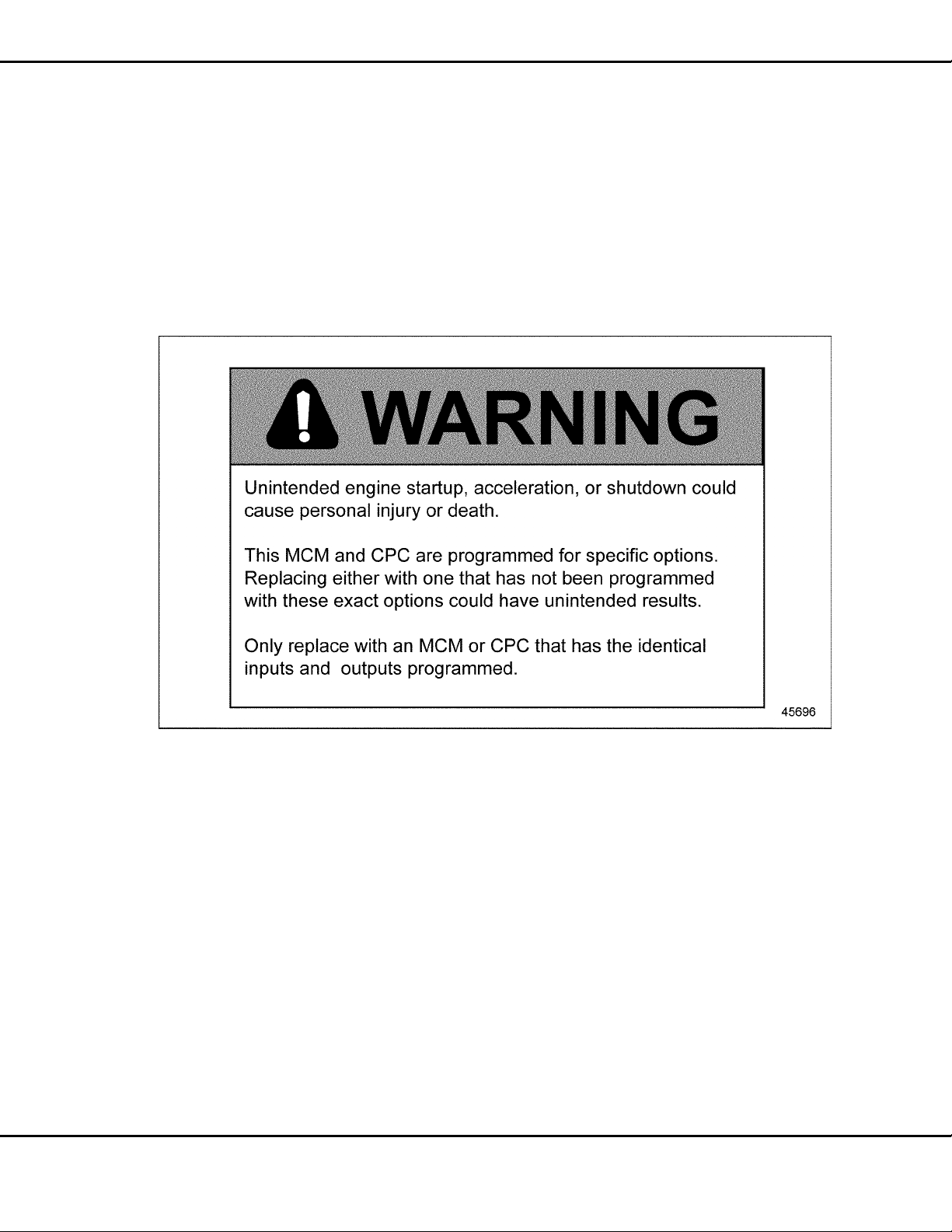
MCM/CPC WARNING
Figure 1 MCM/CPC Replacement Warning
SOFTWARE UPGRADES
NOTE:
These engines are equipped with DaimlerChrysler software. T his software generally
assures optimal engine performance. The installation of software upgrades may cause
minor changes in features and engine performance.
ABSTRACT
This manual provides instruction for troubleshooting DDEC® VI Series 60® engines.
Specifically covered in this manual are troubleshooting and repair steps that apply to the DDEC
VI.
All information subject to change without notice.
Copyright © 2007 DETROIT DIESEL CORPORATION i
Page 4

SERIES 60 DDEC VI TROUBLESHOOTING GUIDE
SAFETY INSTRUCTIONS
To reduce the chance of personal injury and/or property damage, the instructions contained in this
troubleshooting manual must be carefully observed. Proper service and repair are important to the
safety of the service technician and the safe, reliable operation of the engine.
If part replacement is necessary, the part must be replaced with one of the s ame part number or
with an equivalent part number. Do not use a replacement part of lesser quality. The service
procedures recommended and described i n this manual are effective methods of performing
repair. Some of these procedures require the use of specially designed tools. Accordingly, anyone
who intends to use a replacement part, procedure or tool which is not recommended, must first
determine that neither personal safety nor the safe operation of the engine will be jeopardized by
the replacement part, procedure or tool selected.
It is important to note that this m anual contains various hazard notices labeled “Warnings,
“Cautions" and "Notices" that must be carefully observed in order to reduce the risk of personal
injury during repair, or the possibility that improper repair may damage the engine or render it
unsafe. It is also important to understand that these “Warnings,” "Cautions" and "Notices" are not
exhaustive. It is impossible to warn personnel of all the possible hazardous consequences that
might result from failure to follow these instructions.
A LETTER TO THE TECHNICIANS
Technicians today are required to have computer skills, excellent comprehension of the written
word and possess an extensive diagnostic understanding of the various technological systems and
components. Technicians today must perform at a higher level of efficiency and competency than
their predecessors and at the same time furnish professional quality support.
As the leader in engine computer systems and technology, Detroit Diesel Corporation remains
focused on providing excellence in products, service support and training. As products become
more and more advanced, technicians must become specialized in multiple areas. This
manual is designed with that thought in mind. The Detroit Diesel 2007 Electronics Controls
Troubleshooting Guide will provide you with concentrated information that will allow you to
excel in 2007 Electronics Controls technology.
ii Copyright © 2007 DETROIT DIESEL CORPORATION
All information subject to change without notice.
Page 5

SERIES 60 DDEC VI TROUBLESHOOTING GUIDE
TABLE OF CONTENTS
1 INTRODUCTION
1.1 OVERVIEW .............................................................................................. 1-3
1.2 SCOPE AND USE OF THIS GUIDE ........................................................ 1-4
1.3 SAFETY PRECAUTIONS ........................................................................ 1-6
2LOWOILPRESSURE
2.1 IMPROPER ENGINE OIL LEVEL ............................................................ 2-3
2.2 IMPROPER LUBRICATING OIL VISCOSITY .......................................... 2-4
2.3 LUBRICATING OIL DILUTED WITH FUEL OIL OR ENGINE COOLANT 2-5
2.4 FAULTY OIL PRESSURE GAUGE SENSOR .......................................... 2-6
2.5 ROCKER ARM SHAFT PLUGS MISSING (NEW OR REBUILT ENGINES
ONLY) ...................................................................................................... 2-7
2.6 RESTRICTED OIL COOLER ................................................................... 2-9
2.7 NONFUNCTIONAL OR STICKING OIL PRESSURE REGULATOR
VALVE ...................................................................................................... 2-10
2.8 DEFECTIVE BYPASS VALVE .................................................................. 2-12
2.9 DEFECTIVE PRESSURE RELIEF VALVE ............................................... 2-13
2.10 DEFECTIVE PICKUP SCREEN TUBE AND SCREEN ASSEMBLY ....... 2-14
2.11 DEFECTIVE CRANKSHAFT MAIN BEARING SHELLS .......................... 2-15
2.12 DEFECTIVE OIL PUMP ASSEMBLY ....................................................... 2-16
2.13 DETECTING INTERNAL FUEL LEAKS ................................................... 2-17
3 MISFIRING CYLINDER
3.1 POOR VEHICLE GROUND ..................................................................... 3-3
3.2 AERATED FUEL ..................................................................................... 3-5
3.3 FAULTY FUEL INJECTOR ....................................................................... 3-6
3.4 FAULTY MOTOR CONTROL MODULE ................................................... 3-7
3.5 WORN OR DAMAGED VALVE OR CYLINDER KIT ................................ 3-8
4 STARTING DIFFICULTY – ENGINE ROTATE S
4.1 EMPTY FUEL TANK ................................................................................ 4-3
4.2 LOW BATTERY VOLTAGE ...................................................................... 4-3
4.3 CORRODED OR DAMAGED BATTERY TERMINALS ............................ 4-4
4.4 DEFECTIVE MAGNETIC SWITCH .......................................................... 4-5
4.5 DEFECTIVE STARTER ............................................................................ 4-6
4.6 LOW CRANKING SPEED ........................................................................ 4-7
4.7 FUEL SUPPLY VALVE ............................................................................. 4-8
4.8 PLUGGED FUEL FILTER(S) .................................................................... 4-9
4.9 FUEL PUMP ............................................................................................ 4-10
4.10 AERATED FUEL ..................................................................................... 4-11
4.11 RESTRICTIVE AIR FILTER ..................................................................... 4-12
4.12 LOW COMPRESSION ............................................................................ 4-13
4.13 EXTENDED CRANK T IME ...................................................................... 4-19
All information subject to change without notice.
Copyright © 2007 DETROIT DIESEL CORPORATION iii
Page 6

SERIES 60 DDEC VI TROUBLESHOOTING GUIDE
4.14 CRANK NO START .................................................................................. 4-21
5 NO START - ENGINE WILL NOT ROTATE
5.1 DISCHARGED BATTERY ........................................................................ 5-3
5.2 DEFECTIVE MAGNETIC SWITCH .......................................................... 5-4
5.3 DEFECTIVE STARTER ............................................................................ 5-5
5.4 INTERNAL ENGINE DAMAGE ................................................................ 5-6
6 EXCESSIVE OIL CONSUMPTION
6.1 EXTERNAL OIL LEAKS ........................................................................... 6-3
6.2 LEAKING OIL COOLER CORE ............................................................... 6-4
6.3 DEFECTIVE AIR COMPRESSOR ........................................................... 6-6
6.4 DEFECTIVE TURBOCHARGER ............................................................. 6-8
6.5 WORNORDAMAGEDVALVEORCYLINDERKIT ................................ 6-9
7 EXCESSIVE CRANKCASE PRESSURE
7.1 OBSTRUCTION OR DAMAGE TO ROCKER COVER BREATHER ........ 7-3
7.2 DEFECTIVE AIR COMPRESSOR ........................................................... 7-4
7.3 DEFECTIVE TURBOCHARGER ............................................................. 7-6
7.4 WORNORDAMAGEDVALVEORCYLINDERKIT ................................ 7-7
8 EXCESSIVE EXHAUST SMOKE - BLACK OR GRAY
8.1 IMPROPER GRADE OF DIESEL FUEL .................................................. 8-3
8.2 RESTRICTED AIR CLEANER ELEMENT ............................................... 8-4
8.3 RESTRICTED OR CRACKED CHARGE AIR COOLER .......................... 8-5
8.4 FAULTY E XHAUST SYS TEM .................................................................. 8-7
8.5 FAULTY FUEL INJECTOR ....................................................................... 8-8
8.6 DEFECTIVE TURBOCHARGER ............................................................. 8-9
9 EXCESSIVE BLUE SMOKE
9.1 DEFECTIVE TURBOCHARGER ............................................................. 9-3
9.2 WORNORDAMAGEDVALVEORCYLINDERKIT ................................ 9-5
10 EXCESSIVE WHITE SMOKE
10.1 IMPROPER GRADE OF FUEL ................................................................ 10-3
10.2 DEFECTIVE FUEL PUMP ....................................................................... 10-4
10.3 AERATED FUEL ..................................................................................... 10-6
10.4 IMPROPER INJECTOR CALIBRATION SETTING .................................. 10-7
10.5 IMPROPER VALVE CLEARANCE OR INJECTOR HEIGHT, WORN OR
DAMAGED CAMSHAFT LOBES AND ROLLERS .................................. 10-8
10.6 FAULTY FUEL INJECTOR ....................................................................... 10-9
11 ROUGH RUNNING OR STALLING
11.1 LOW BATTERY VOLTAGE ...................................................................... 11-3
11.2 AERATED FUEL ...................................................................................... 11-4
11.3 INSUFF ICIENT FUEL FLOW ................................................................... 11-4
11.4 HIGH FUEL TEMPERATURE RETURN .................................................. 11-6
11.5 IMPROPER INJECTOR CALIBRATION SETTING .................................. 11-8
11.6 LOW COMPRESSION PRESSURE ........................................................ 11-8
iv Copyright © 2007 DETROIT DIESEL CORPORATION
All information subject to change without notice.
Page 7

SERIES 60 DDEC VI TROUBLESHOOTING GUIDE
12 LOW POWER
12.1 FACTORS THAT AFFECT WHEEL HORSEPOWER .............................. 12-3
12.2 LOW HORSEPOWER INTERVIEW ......................................................... 12-6
12.3 AERATED FUEL ..................................................................................... 12-12
12.4 HIGH FUEL PRESSURE ......................................................................... 12-13
12.5 HIGH FUEL TEMPERATURE RETURN .................................................. 12-16
12.6 RESTRICTED AIR CLEANER ELEMENT ............................................... 12-17
12.7 RESTRICTED OR CRACKED CHARGE AIR COOLER OR LEAKING
INTA KE MANIFOLD ................................................................................. 12-18
12.8 FAULTY EXHAUST SYSTEM .................................................................. 12-20
12.9 HIGH INLET AIR TEMPERATURE .......................................................... 12-21
12.10 HIGH ALTITUDE OPERATION ................................................................ 12-22
12.11 INCORRECT CAMSHAFT TIMING ......................................................... 12-24
12.12 POWER VERIFICATION WITH CHASSIS DYNAMOMETER ................. 12-25
13 HIGH ENGINE COOLANT TEMPERATURE
13.1 IMPROPER ENGINE COOLANT LEVEL ................................................. 13-3
13.2 INSUFFICIENT RADIATOR AIR CIRCULATION ..................................... 13-5
13.3 FAULTY PRESSURE CONTROL CAP .................................................... 13-6
13.4 DEFECTIVE COOLANT HOSES ............................................................. 13-7
13.5 FAN BELTS ARE INCORRECTLY ADJUSTED ....................................... 13-8
13.6 INOPERATIVE THERMO-MODULATED FAN ......................................... 13-9
13.7 FAULTY THERMOSTATS ....................................................................... 13-10
13.8 FAULTY WATER PUMP ........................................................................... 13-11
13.9 COMBUSTION GASES IN COOLANT .................................................... 13-13
13.10 ABNORMAL RADIATOR COOLANT FLOW ............................................ 13-19
14 LOW COOLANT TEMPERATURE
14.1 FAULTY THERMOSTATS ....................................................................... 14-3
15 POOR FUEL ECONOMY
15.1 SOFTWARE VERSION ............................................................................ 15-3
16 AIR COMPRESSOR
16.1 AIR COMPRESSOR TROUBLESHOOTING ........................................... 16-3
17 DDEC VI SYSTEM
17.1 DDEC VI SYSTEM--HOW IT WORKS ..................................................... 17-3
17.2 MOTOR CONTROL MODULE ................................................................ 17-3
17.3 COMMON POWERTRAIN CONTROLLER ............................................. 17-11
17.4 WIRES AND WIRING .............................................................................. 17-21
17.5 CONDUIT AND LOOM ............................................................................. 17-35
17.6 TAPE AND TAPING ................................................................................. 17-36
17.7 SENSORS ................................................................................................ 17-37
17.8 INSTRUMENT PANEL LAMPS ................................................................ 17-51
18 ENGINE MANUFACTURER DIAGNOSTIC S
18.1 ENGINE MANUFACTURER DIAGNOSTICS DEFINITIONS ................... 18-3
18.2 ENGINE MANUFACTURER DIAGNOSTICS PARAMETER
DESCRIPTIONS ...................................................................................... 18-4
All information subject to change without notice.
Copyright © 2007 DETROIT DIESEL CORPORATION v
Page 8

SERIES 60 DDEC VI TROUBLESHOOTING GUIDE
19 SPN 27 - EGR VALVE POSITION CIRCUIT FAULT
19.1 SPN 27/FMI 3 ........................................................................................... 19-3
19.2 SPN 27/FMI 4 ........................................................................................... 19-4
19.3 SPN 27/FMI 7 ........................................................................................... 19-7
20 SPN 51 - INTAKE THROTTLE VALVE ABOVE OR BELOW NORMAL
OPERATING RANGE
20.1 SPN 51/FMI 2, 3 OR 4 ............................................................................. 20-3
21 SPN 70 (CPC) - J1939 PARK BRAKE SWITCH SIGNAL ERRATIC
OR MISSING
21.1 SPN 70/FMI 13 ......................................................................................... 21-3
21.2 SPN 70/FMI 19 ......................................................................................... 21-3
22 SPN 84 (CPC) - J1939 WHEEL-BASED VEHICLE SPEED SIGNAL
ERRATICORMISSING
22.1 SPN 84/FMI 13 ......................................................................................... 22-3
22.2 SPN 84/FMI 19 ......................................................................................... 22-3
23 SPN 84 (CPC) – VEHICLE SPEED SENSOR
23.1 SPN 84/FMI 2 ........................................................................................... 23-3
23.2 SPN 84/FMI 3 ........................................................................................... 23-3
23.3 SPN 84/FMI 4 ........................................................................................... 23-4
23.4 SPN 84/FMI 6 ........................................................................................... 23-4
23.5 SPN 84/FMI 8 ........................................................................................... 23-5
24 SPN 91 (CPC) – ACCELERATOR PEDAL SENSOR FAULT
24.1 SPN 91/FMI 2 ........................................................................................... 24-3
24.2 SPN 91/FMI 3 ........................................................................................... 24-4
24.3 SPN 91/FMI 4 ........................................................................................... 24-5
25 SPN 94 – FU EL COMPENSATION PRESSURE SENSOR CIRCUIT
FAULT
25.1 SPN 94/FMI 3 OR 4 ................................................................................. 25-3
26 SPN 100 — ENGINE OIL PRESSURE OUTSIDE OF NORMAL
OPERATING RANGE
26.1 SPN 100/FMI 1 ......................................................................................... 26-3
26.2 SPN 100/FMI 3 ......................................................................................... 26-4
26.3 SPN 100/FMI 4 ......................................................................................... 26-6
26.4 SPN 100/FMI 18 ....................................................................................... 26-8
27 SPN 103 – TURBO NO REVOLUTION
27.1 SPN 103/FMI 0 ........................................................................................ 27-3
27.2 SPN 103/FMI 1 ........................................................................................ 27-4
27.3 SPN 103/FMI 4 ......................................................................................... 27-5
28 SPN 108 - BAROMETRIC PRESSURE SENSOR CIRCUIT FAULT
28.1 SPN 108/FMI 3 ......................................................................................... 28-3
28.2 SPN 108/FMI 4 ......................................................................................... 28-3
vi Copyright © 2007 DETROIT DIESEL CORPORATION
All information subject to change without notice.
Page 9

SERIES 60 DDEC VI TROUBLESHOOTING GUIDE
29 SPN 110 — COOLANT TEMPERATURE ABOVE OR BELOW NORMAL
OPERATING RANGE
29.1 SPN 110/FMI 0 ......................................................................................... 29-3
29.2 SPN 110/FMI 3 ......................................................................................... 29-3
29.3 SPN 110/FMI 4 ......................................................................................... 29-6
29.4 SPN 110/FMI 14 ....................................................................................... 29-7
29.5 SPN 110/FMI 16 ....................................................................................... 29-8
30 SPN 111 (CPC) – COOLANT LEVEL OUTSIDE NORMAL OPERATING
RANGE
30.1 SPN 111/FMI 1 ......................................................................................... 30-3
30.2 SPN 111/FMI 3 ......................................................................................... 30-5
30.3 SPN 111/FMI 4 ......................................................................................... 30-7
31 SPN 132 - AIR MASS FLOW NOT NORMAL
31.1 SPN 132/FMI1 .......................................................................................... 31-3
32 SPN 168 – BATTERY VOLTAGE OUTSIDE NORMAL OPERATING
RANGE
32.1 SPN 168/FMI 0 ......................................................................................... 32-3
32.2 SPN 168/FMI 1 ......................................................................................... 32-4
33 SPN 171 (CPC) - J1587 AMBIENT AIR TEMPERATURE SENSOR
DATA NOT RECEIVED
33.1 SPN 171/FMI 9 ......................................................................................... 33-3
33.2 SPN 171/FMI 14 ....................................................................................... 33-3
34 SPN 174 – SUPPLY FUEL TEMPERATURE FAULT
34.1 SPN 174/FMI 3 ......................................................................................... 34-3
34.2 SPN 174/FMI 4 ......................................................................................... 34-5
35 SPN 175 – ENGINE OIL TEMPERATURE OUT OF NORMAL RANGE
35.1 SPN 175/FMI 3 ......................................................................................... 35-3
35.2 SPN 175/FMI 4 ......................................................................................... 35-5
35.3 SPN 175/FMI 14 ....................................................................................... 35-5
36 SPN 190 - E NGINE SPEED HIGH
36.1 SPN 190/FMI 2 ......................................................................................... 36-3
37 SPN 191 (CPC) - J1939 ETC1 MESSAGE MISSING AND
TRANSMISSION OUTPUT SHAFT SPEED SIGNAL ERRATIC OR
MISSING
37.1 SPN 191/FMI 9 ......................................................................................... 37-3
37.2 SPN 191/FMI 13 ....................................................................................... 37-3
37.3 SPN 191/FMI 19 ....................................................................................... 37-4
38 SPN 247 (CPC) – MCM ENGINE HOURS DATA HIGHER OR LOWER
THAN EXPECTED
38.1 SPN 247/FMI 0 ......................................................................................... 38-3
38.2 SPN 247/FMI 1 ......................................................................................... 38-3
38.3 SPN 247/FMI 9 ......................................................................................... 38-4
All information subject to change without notice.
Copyright © 2007 DETROIT DIESEL CORPORATION vii
Page 10

SERIES 60 DDEC VI TROUBLESHOOTING GUIDE
39 SPN 411 — EGR DIFFERENT IA L PRESSURE OR DELTA P SENSOR
CIRCUIT OUTSIDE OF NORMAL OPERATING RANGE
39.1 SPN 411/FMI 0 ......................................................................................... 39-3
39.2 SPN 411/FMI 3 ......................................................................................... 39-4
39.3 SPN 411/FMI 4 ......................................................................................... 39-6
39.4 SPN 411/FMI 13 ....................................................................................... 39-8
40 SPN 412 - EGR TEMPERATURE IS OUTSIDE OF THE NORMAL
RANGE
40.1 SPN 412/FMI 3 ......................................................................................... 40-3
40.2 SPN 412/FMI 4 ......................................................................................... 40-6
40.3 SPN 412/FMI 16 ....................................................................................... 40-8
40.4 SPN 412/FMI 20 ....................................................................................... 40-9
41 SPN 523 (CPC) - TRANSMISSION CURRENT GEAR SIGNAL
ERRATICORMISSING
41.1 SPN 523/FMI 19 ....................................................................................... 41-3
41.2 SPN 523/FMI 13 ....................................................................................... 41-3
42 SPN 524 (CPC) - J1939 ETC2 MESSAGE IS M ISSING
42.1 SPN 523/FMI 9 ......................................................................................... 42-3
43 SPN 527 (CPC) - J1939 CCVS MESSAGE MISSING
43.1 SPN 527/FMI 9 ......................................................................................... 43-3
44 SPN 558 (CPC) - IDLE VALIDATION SWITCH
44.1 SPN 558/FMI 1 ......................................................................................... 44-3
44.2 SPN 558/FMI 3 ......................................................................................... 44-3
44.3 SPN 558/FMI 4 ......................................................................................... 44-5
45 SPN 596 (CPC) - CRUISE CONTROL ENABLE SWITCH SIGNAL
ERRATICORMISSING
45.1 SPN 596/FMI 13 ....................................................................................... 45-3
45.2 SPN 596/FMI 19 ....................................................................................... 45-3
46 SPN 597 (CPC) - SERVICE BRAKE SWITCH SIGNAL ERRATIC OR
MISSING
46.1 SPN 597/FMI 13 ....................................................................................... 46-3
46.2 SPN 597/FMI 19 ....................................................................................... 46-3
47 SPN 599 (CPC) - CRUISE CONTROL SWITCHES N OT FUNCTIONIN G
PROPERLY
47.1 SPN 599/FMI 4 ......................................................................................... 47-3
48 SPN 600 (CPC) - CRUISE CONTROL COAST SWITCH SIGNAL
ERRATICORMISSING
48.1 SPN 600/FMI 13 ....................................................................................... 48-3
48.2 SPN 600/FMI 19 ....................................................................................... 48-3
viii Copyright © 2007 DETROIT DIESEL CORPORATION
All information subject to change without notice.
Page 11

SERIES 60 DDEC VI TROUBLESHOOTING GUIDE
49 SPN 602 (CPC) - CRUISE CONTR OL ACCELERATE SWITCH SIGNAL
ERRATICORMISSING
49.1 SPN 602/FMI 13 ....................................................................................... 49-3
49.2 SPN 602/FMI 19 ....................................................................................... 49-3
50 SPN 609 - MCM FAULT (ERRONEOUS DATA)
50.1 SPN 609/FMI 12 ....................................................................................... 50-3
50.2 SPN 609/FMI 14 ....................................................................................... 50-4
51 SPN 615 (CPC) - J1939 DM1 MESSAGE FROM TRANSMISSION
MISSING
51.1 SPN 615/FMI 9 ......................................................................................... 51-3
52 SPN 625 - CAN FAULT
52.1 SPN 625/FMI 2 ........................................................................................ 52-3
52.2 SPN 625/FMI 9 ........................................................................................ 52-5
53 SPN 628 (CPC) - MULTIPLE FAULTS
53.1 SPN 628/FMI 13 (ALL FAULT DESCRIPTIONS) ..................................... 53-3
53.2 SPN 628/FMI 14 ....................................................................................... 53-3
54 SPN 629 (CPC) - MULTIPLE FAULTS
54.1 SPN 629/FMI 2 ......................................................................................... 54-3
54.2 SPN 629/FMI 12 ....................................................................................... 54-4
55 SPN 630 (CPC) - MULTIPLE FAULTS
55.1 SPN 630/FMI 14 ....................................................................................... 55-3
56 SPN 636 — CRANKSHAFT POSITION SENSOR OUTSIDE OF
NORMAL OPERATING CONDITIONS
56.1 SPN 636/FMI 1 ......................................................................................... 56-3
56.2 SPN 636/FMI 3 ......................................................................................... 56-4
56.3 SPN 636/FMI 4 ......................................................................................... 56-6
56.4 SPN 636/FMI 7 ......................................................................................... 56-7
56.5 SPN 636/FMI 8 ......................................................................................... 56-9
56.6 SPN 636/FMI 14 ....................................................................................... 56-11
57 SPN 641 - SMART REMOTE ACTUATOR 5 (VGT) ABNORMAL
OPERATION
57.1 SPN 641/FMI 7 ......................................................................................... 57-3
57.2 SPN 641/FMI 8 ......................................................................................... 57-5
57.3 SPN 641/FMI 9 ......................................................................................... 57-6
57.4 SPN 641/FMI 11 ....................................................................................... 57-7
57.5 SPN 641/FMI 14 ....................................................................................... 57-9
57.6 SPN 641/FMI 31 ....................................................................................... 57-12
58 SPN 647 - SINGLE-SPEED FAN (LOW-SIDE DIGITAL OUTPUT #3)
FAULT
58.1 SPN 647/FMI 3 ......................................................................................... 58-3
58.2 SPN 647/FMI 4 ......................................................................................... 58-4
58.3 SPN 647/FMI 5 ......................................................................................... 58-5
All information subject to change without notice.
Copyright © 2007 DETROIT DIESEL CORPORATION ix
Page 12

SERIES 60 DDEC VI TROUBLESHOOTING GUIDE
59 SPN 651 – INJECTOR #1 NEEDLE VALVE NOT OPERATING
NORMALLY
59.1 SPN 651/FMI 14 ....................................................................................... 59-3
60 SPN 652 – INJECTOR #2 NEEDLE VALVE NOT OPERATING
NORMALLY
60.1 SPN 652/FMI 14 ....................................................................................... 60-3
61 SPN 653 – INJECTOR #3 NEEDLE VALVE NOT OPERATING
NORMALLY
61.1 SPN 653/FMI 14 ....................................................................................... 61-3
62 SPN 654 – INJECTOR #4 NEEDLE VALVE NOT OPERATING
NORMALLY
62.1 SPN 654/FMI 14 ....................................................................................... 62-3
63 SPN 655 – INJECTOR #5 NEEDLE VALVE NOT OPERATING
NORMALLY
63.1 SPN 655/FMI 14 ....................................................................................... 63-3
64 SPN 656 – INJECTOR #6 NEEDLE VALVE NOT OPERATING
NORMALLY
64.1 SPN 656/FMI 14 ....................................................................................... 64-3
65 SPN 703 (CPC) - ASG2 BACKUP LAMP
65.1 SPN 703/FMI 3 ......................................................................................... 65-3
65.2 SPN 703/FMI 4 ......................................................................................... 65-3
66 SPN 704 (CPC) - HIGH EXHAUST SYSTEM TEMPERATURE LAMP
66.1 SPN 704/FMI 3 ......................................................................................... 66-3
66.2 SPN 704/FMI 4 ......................................................................................... 66-3
67 SPN 704 - TURBO ACTUATOR CONTROL (AUX PWM #10)
67.1 SPN 704/FMI 3 ......................................................................................... 67-3
67.2 SPN 704/FMI 4 ......................................................................................... 67-4
67.3 SPN 704/FMI 5 ......................................................................................... 67-5
68 SPN 705 (CPC) - MALFUNCTION INDICATOR LAMP
68.1 SPN 705/FMI 3 ......................................................................................... 68-3
68.2 SPN 705/FMI 4 ......................................................................................... 68-3
69 SPN 706 (CPC) - ASG2 CHECK TRANS TEMP LAMP
69.1 SPN 706/FMI 3 ......................................................................................... 69-3
69.2 SPN 706/FMI 4 ......................................................................................... 69-3
70 SPN 707 (CPC) - AMBER WARNING LAMP
70.1 SPN 707/FMI 3 ......................................................................................... 70-3
70.2 SPN 707/FMI 4 ......................................................................................... 70-3
71 SPN 708 (CPC) - ASG2 CHECK TRANS LAMP
71.1 SPN 708/FMI 3 ......................................................................................... 71-3
71.2 SPN 708/FMI 4 ......................................................................................... 71-3
x Copyright © 2007 DETROIT DIESEL CORPORATION
All information subject to change without notice.
Page 13

SERIES 60 DDEC VI TROUBLESHOOTING GUIDE
72 SPN 709 (CPC) - RED STOP LAMP
72.1 SPN 709/FMI 3 ......................................................................................... 72-3
72.2 SPN 709/FMI 4 ......................................................................................... 72-3
73 SPN 711 (CPC) - DPF REGEN LAMP
73.1 SPN 711/FMI 3 ......................................................................................... 73-3
73.2 SPN 711/FMI 4 ......................................................................................... 73-3
74 SPN 713 (CPC) - TOP2 LOCKOUT SOLENOID
74.1 SPN 713/FMI 3 ......................................................................................... 74-3
74.2 SPN 713/FMI 4 ......................................................................................... 74-3
74.3 SPN 713/FMI 5 ......................................................................................... 74-3
74.4 SPN 713/FMI 7 ......................................................................................... 74-3
75 SPN 714 (CPC) - TOP2 SHIFT SOLENOID
75.1 SPN 714/FMI 3 ......................................................................................... 75-3
75.2 SPN 714/FMI 4 ......................................................................................... 75-3
75.3 SPN 714/FMI 5 ......................................................................................... 75-3
76 SPN 715 (CPC) - VEHICLE POWER SHU TDOWN
76.1 SPN 715/FMI 3 ......................................................................................... 76-3
76.2 SPN 715/FMI 4 ......................................................................................... 76-3
76.3 SPN 715/FMI 5 ......................................................................................... 76-3
77 SPN 723 – CAMSHAFT POSITION SENSOR FAULT
77.1 SPN 723/FMI 3 ......................................................................................... 77-3
77.2 SPN 723/FMI 4 ......................................................................................... 77-5
77.3 SPN 723/FMI 8 ......................................................................................... 77-6
77.4 SPN 723/FMI 14 ....................................................................................... 77-7
78 SPN 904 (CPC) - J1939 EBC2 MESSAGE MISSING AND FRONT
AXLE SPEED SIGNAL ERRATIC OR MISSING
78.1 SPN 904/FMI 9 ......................................................................................... 78-3
78.2 SPN 904/FMI 13 ....................................................................................... 78-3
78.3 SPN 904/FMI 19 ....................................................................................... 78-4
79 SPN 973 (CPC) - J1939 EBC1 MESSAGE MISSING AND ENGINE
RETARDER SELECTION SIGNAL IS ERRATIC OR MISSSING
79.1 SPN 973/FMI 9 ......................................................................................... 79-3
79.2 SPN 973/FMI 13 ....................................................................................... 79-3
79.3 SPN 973/FMI 19 ....................................................................................... 79-4
80 SPN 986 (CPC) - J1939 CM1 MESSAGE IS MISSING
80.1 SPN 986/FMI 9 ......................................................................................... 80-3
81 SPN 1071 - TWO-SPEED FAN (AUX PWM #6) FAULT
81.1 SPN 1071/FMI 3 ....................................................................................... 81-3
81.2 SPN 1071/FMI 4 ....................................................................................... 81-4
81.3 SPN 1071/FMI 5 ....................................................................................... 81-5
All information subject to change without notice.
Copyright © 2007 DETROIT DIESEL CORPORATION xi
Page 14

SERIES 60 DDEC VI TROUBLESHOOTING GUIDE
82 SPN1072–JAKEBRAKESSTAGE1(AUXPWM#7)OPENOR
SHORT
82.1 SPN 1072/FMI 4 ....................................................................................... 82-3
82.2 SPN 1072/FMI 5 ....................................................................................... 82-4
83 SPN 1073 – JAKE BRAKE STAGE 2 (AUX PWM #13) OPEN OR
SHORT
83.1 SPN 1073/FMI 4 ....................................................................................... 83-3
83.2 SPN 1073/FMI 5 ....................................................................................... 83-4
84 SPN1172-TURBOCOMPRESSORINTEMPHIGHORLOW
84.1 SPN 1172/FMI 2 ....................................................................................... 84-3
84.2 SPN 1172/FMI 3 ....................................................................................... 84-3
84.3 SPN 1172/FMI 4 ....................................................................................... 84-6
85 SPN 1590 (CPC) - J1939 ACC1 MESSAGE FROM ADAPTIVE CRUISE
CONTROL IS MISSING
85.1 SPN 1590/FMI 9 ....................................................................................... 85-3
86 SPN 1624 (CPC) - J1939 TCO1 MESSAGE IS MISSING AND
TACHOGRAPH VEHICLE SPEED SIGNAL IS ERRATIC AND MISSING
86.1 SPN 1624/FMI 9 ....................................................................................... 86-3
86.2 SPN 1624/FMI 13 ..................................................................................... 86-3
86.3 SPN 1624/FMI 19 ..................................................................................... 86-4
87 SPN 1636 – INTAKE AIR TEMPERATURE OUTSIDE OF NORMAL
OPERATING RANGE
87.1 SPN 1636/FMI 3 ....................................................................................... 87-3
87.2 SPN 1636/FMI 4 ....................................................................................... 87-5
87.3 SPN 1636/FMI 20 ..................................................................................... 87-6
87.4 SPN 1636/FMI 21 ..................................................................................... 87-7
87.5 SPN 1636/FMI 31 ..................................................................................... 87-8
88 SPN 1716 (CPC) - J1939 ERC1 MESSAGE IS MISSING
88.1 SPN 1716/FMI 9 ....................................................................................... 88-3
89 SPN 1845 (CPC) - J1939 TCFG2 MESSAGE IS MISSING
89.1 SPN 1845/FMI 9 ....................................................................................... 89-3
90 SPN 2623 (CPC) - PWM ACCELERATOR PEDAL GAS1 AND GAS2
SIGNAL MISSING
90.1 SPN 2623/FMI 4 ....................................................................................... 90-3
90.2 SPN 2623/FMI 14 ..................................................................................... 90-3
91 SPN 2629 - TURBO COMPRESSOR OUT TEMP HIGH OR LOW
91.1 SPN 2629/FMI 3 ....................................................................................... 91-3
91.2 SPN 2629/FMI 4 ....................................................................................... 91-6
91.3 SPN 2629/FMI 20 ..................................................................................... 91-7
91.4 SPN 2629/FMI 21 ..................................................................................... 91-8
xii Copyright © 2007 DETROIT DIESEL CORPORATION
All information subject to change without notice.
Page 15

SERIES 60 DDEC VI TROUBLESHOOTING GUIDE
92 SPN 2659 - EGR FLOW NOT NORMAL
92.1 SPN 2659/FMI 0 ....................................................................................... 92-3
92.2 SPN 2659/FMI 1 ....................................................................................... 92-4
93 SPN 2791 – EGR VALVE (AUX PWM #1) FAILED OR OPEN CIRCUIT
93.1 SPN 2791/FMI 3 ....................................................................................... 93-3
93.2 SPN 2791/FMI 4 ....................................................................................... 93-4
93.3 SPN 2791/FMI 5 ....................................................................................... 93-4
93.4 SPN 2791/FMI 7 ....................................................................................... 93-6
94 SPN 2795 - CAN COMMUNICATION ERROR
94.1 SPN 2795/FMI 9 ....................................................................................... 94-3
95 SPN 2797 - INJECTOR #1, 2, OR 3 NEEDLE OR SPILL CONTROL
VALVE NOT OPERATING NORMALLY
95.1 SPN 2797/FMI 3 ....................................................................................... 95-3
95.2 SPN 2797/FMI 4 ....................................................................................... 95-4
95.3 SPN 2797/FMI 5 ....................................................................................... 95-6
95.4 SPN 2797/FMI 6 ....................................................................................... 95-7
96 SPN 2798 - INJECTOR #4, 5, OR 6 NEEDLE OR SPILL CONTROL
VALVE NOT OPERATING NORMALLY
96.1 SPN 2798/FMI 3 ....................................................................................... 96-3
96.2 SPN 2798/FMI 4 ....................................................................................... 96-4
96.3 SPN 2798/FMI 5 ....................................................................................... 96-6
96.4 SPN 2798/FMI 6 ....................................................................................... 96-7
97 SPN 2900 (CPC) - J1939 ETC7 MESSAGE IS MISSING
97.1 SPN 2900/FMI 9 ....................................................................................... 97-3
98 SPN 3050 - E NGINE AIR FLOW ABOVE OR BELOW NORMAL
OPERATING RANGE
98.1 SPN 3050 ................................................................................................. 98-3
99 SPN 3242 - DOC INLET TEMPERATURE SENSOR ABOVE OR
BELOW NORMAL OPERATING RANGE
99.1 SPN 3242/FMI 2, 3,
100 SPN 3246 - DPF OUT
4 OR 10 ...................................................................
LET TEMPERATURE SENSOR OPERATING
99-3
ABOVE OR BELOW NORMAL
100.1 SPN 3246/FMI 0, 2, 3, 4, 10, 14, 31 ......................................................... 100-3
101 SPN 3250 - DPF INLET TEMPERATURE SENSOR ABOVE OR BELOW
NORMAL OPER
ATING RANGE
101.1 SPN 3250/FMI 0, 2, 3, 4, 10, 14, 31 ......................................................... 101-3
102 SPN 3251 - DPF OUTLET PRESSURE ABOVE OR BELOW NORMAL
OPERATING RANGE
102.1 SPN 325
1/FMI 0, 1 OR 16 .......................................................................
102-3
All information subject to change without notice.
Copyright © 2007 DETROIT DIESEL CORPORATION xiii
Page 16

SERIES 60 DDEC VI TROUBLESHOOTING GUIDE
103 SPN 3471 - ELECTRONIC DOSING VALVE SENSOR ABOVE OR
BELOW NORMAL OPERATING RANGE
103.1 SPN 34 71/FMI 1, 3, 4 OR 5 ..................................................................... 103-3
104 SPN 3480 - FUEL LINE PRESSURE SENSOR ABOVE OR BELOW
NORMAL OPERATING RANGE
104.1 SPN 3480/FMI 1, 2 OR 14 ....................................................................... 104-3
105 SPN 3482 - FUEL CUTOFF VALVE SENSOR ABOVE OR BELOW
NORMAL OPERATING RANGE
105.1 SPN 34 82/FMI 3, 4, 5 OR 7 ..................................................................... 105-3
106 SPN 3509 - MULTIPLEXER 1 CHANNEL 1 OR 2 SHORT OR OPEN
CIRCUIT HIGH
106.1 SPN 3509/FMI 3 ....................................................................................... 106-3
107 SPN 3510 - MULTIPLEXER 2 CHANNEL 1 OR 2 SHORT OR OPE
N
CIRCUIT HIGH
107.1 SPN 3510/FMI 3 ....................................................................................... 107-3
108 SPN 3510 – ACCELERATOR PEDAL SUPPLY OUTSIDE OF NORMAL
OPERATING RANGE
108.1 SPN 3510/FMI 2 ....................................................................................... 108-3
108.2 SPN 3510/FMI 3 ....................................................................................... 108-5
108.3 SPN 3510/FMI 4 ....................................................................................... 108-6
109 SPN 3511 - MULTIPLEXER 3 CHANNEL 1 0R 2 SHORT OR OPEN
CIRCUIT HIGH
109.1 SPN 3511/FMI 3 ....................................................................................... 109-3
110 SPN 3556 - ELECTRONIC DOSING VALVE ABOVE OR BELOW
NORMAL OPERATING RANGE
110.1 SPN 3556/FMI 0 OR 1 ............................................................................. 110-3
111 SPN 3563– INTAKE MANI
FOLD PRESSURE OUTSIDE NORMAL
RANGE
111.1 SPN 3563/FMI 0 ....................................................................................... 111-3
111.2 SPN 3563/FMI 1 ....................................................................................... 111-4
111.3 SPN 3563/FMI 3 ....................................................................................... 111-5
111.4 SPN 3563/FMI 4 ....................................................................................... 111-6
111.5 SPN 3563/FMI 20 ..................................................................................... 111-8
111.6 SPN 3563/FMI
21 .....................................................................................
111-12
112 SPN 3588 - ET
HER START (LOW-S IDE DIGITAL OUTPUT #8) FAULT
112.1 SPN 3588/FMI 3 ....................................................................................... 112-3
112.2 SPN 3588/
FMI 4 .......................................................................................
112-4
112.3 SPN 3588/FMI 5 ....................................................................................... 112-5
113 SPN 3597 - PROPORTIONAL VALVE BANK 1 CIRCUIT
113.1 SPN 359
xiv Copyright © 2007 DETROIT DIESEL CORPORAT ION
7/FMI 3 .......................................................................................
All information subject to change without notice.
113-3
Page 17

SERIES 60 DDEC VI TROUBLESHOOTING GUIDE
114 SPN 3603 (CPC) - J1939 ESS MESSAGE IS MISSING
114 .1 SPN 3603/FMI 9 ....................................................................................... 114-3
115 SPN 3609 - DPF INLET PRESSURE SENSOR ABOVE OR BELOW
NORMAL OPERATING RANGE
115 .1 SPN 3609FMI 2, 3, 4, 10, 20 OR 21 ........................................................ 115-3
116 SPN 3610 - DPF OUTLET PRESSURE SENSOR ABOVE OR BELOW
NORMAL OPERATING RANGE
116 .1 SPN 3610/FMI 2, 3, 4, 14, 20 OR 21 ....................................................... 116-3
117 SPN 3659 – INJECTOR #1 SPILL VALVE NOT OPERATING
NORMALLY
117 .1 SPN 3659/FMI 14 ..................................................................................... 117-3
118 SPN 3660 - INJECTOR #2 SPILL VALVE NOT OPERATING
NORMALLY
118 .1 SPN 3660/FMI 14 ..................................................................................... 118-3
119 SPN 3661 - INJECTOR #3 SPILL VALVE NOT OPERATING
NORMALLY
119 .1 SPN 3661/FMI 14 ..................................................................................... 119-3
120 SPN 3662 - INJECTOR #4 SPILL VA LVE NOT
OPERATING
NORMALLY
120.1 SPN 3662/FMI 14 ..................................................................................... 120-3
121 SPN 3663 - INJECTOR #5 SPILL VALVE NOT OPERATING
NORMALLY
121.1 SPN 3663/FMI 14 ..................................................................................... 121-3
122 SPN 3664 - INJECTOR #6 SPILL VALVE NOT OPERATING
NORMALLY
122.1 SPN 3664/FMI 14 ..................................................................................... 122-3
123 SPN 3695 (CPC) - DPF RE
GEN MUX SWITCH MESSAGES NOT
OPERATING NORMALLY
123.1 SPN 3695/FMI 9 ....................................................................................... 123-3
123.2 SPN 3695/FMI 13 ..................................................................................... 123-4
123.3 SPN 3695/FMI 14
.....................................................................................
123-4
123.4 SPN 3695/FMI 19 ..................................................................................... 123-5
124 SPN 3719 - SOOT LEVEL ABOVE NORMAL
124.1 SPN 3719/FM
125 SPN 3798 - P
I 0, 15,16,OR 31 ................................................................
ROPORTIONAL VALVE BANK 2 CIRCUIT
124-3
125.1 SPN 3798/FMI 4 ....................................................................................... 125-3
126 SPN 3720 - ASH LEVEL ABOVE NORMAL
126.1 SPN 3720/FMI 15 OR 16 ......................................................................... 126-3
127 SPN 4077 FUEL LINE PRESSURE SENSOR CIRCUIT FAULT
127.1 SPN 40
All information subject to change without notice.
Copyright © 2007 DETROIT DIESEL CORPORATION xv
77/FMI 3, 4 OR 14 .......................................................................
127-3
Page 18

SERIES 60 DDEC VI TROUBLESHOOTING GUIDE
128 SPN 4228 - VGT TEMPERATURE WARNING
128.1 SPN 4228/FMI 15 ..................................................................................... 128-3
128.2 SPN 4228/FMI 16 ..................................................................................... 128-4
129 DDEC VI SCHEMATICS
129.1 CRUISE CONTROL ................................................................................. 129-3
129.2 FAN CONTROL ........................................................................................ 129-4
129.3 OPTIMIZED IDLE ..................................................................................... 129-10
xvi Copyright © 2007 DETROIT DIESEL CORPORAT ION
All information subject to change without notice.
Page 19

1 INTRODUCTION
Section Page
1.1 OVERVIEW .............................................................................................. 1-3
1.2 SCOPE AND USE OF THIS GUIDE ........................................................ 1-4
1.3 SAFETY PRECAUTIONS ........................................................................ 1-6
Page 20

1-2 Copyright © 2007 DETROIT DIESEL CORPORATION
All information subject to change without notice.
Page 21

1.1 OVERVIEW
SERIES 60 DDEC VI TROUBLESHOOTING GUIDE
Detroit Diesel Corporation is the world leader in diesel engines and diesel engine e
lectronics.
DDC has made technological leaps in engine performance and fuel economy. Today, we build the
most dependable electronically controlled diesel engine in the industry.
Detroit Diesel Electronic Controls VI (DDEC®) provides two industry s
tandard serial data links:
SAE Standards J1587 and J1939. SAE Standard J1587 provides two way communications for the
diagnostic equipment and vehicle displays. SAE Standard J1939 provides control data to other
vehicle systems such as transmissions and traction control devic
es.
As the leader in engine computer systems and technology, Detroit Diesel Corporation remains
focused on providing excellence in products, service support and training. As products become
more and more advanced, today’s technicians must become
specialized in multiple areas. This
manual is designed with that thought in mind.
Our goal at Detroit Diesel is to be the most customer focused and most responsive engine
manufacturer in the world.
All information subject to change without notice.
Copyright © 2007 DETROIT DIESEL CORPORATION 1-3
Page 22

1.2 SCOPE AND USE OF THIS GUIDE
1.2 SCOPE AND USE OF THIS GUIDE
The first half of the manual contain mechanical troubleshooting procedures. The sec
ond half
contains instructions for troubleshooting the electronic controls.
This manual is divided into numbered chapters. Each chapter begins with a table of contents.
Pages and illustrations are numbered consecutively within each chapt
er.
Information can be located b y using the table of contents at the front of the manual or the table
of contents at the beginning of each chapter.
Instructions to "Contact Detroit Diesel Customer Service Center" in
dicate that at the time of this
publication, all known troubleshooting checks have been included. Review any recent Service
Information Bulletins (SIB) or Service Information letters before calling.
It is also suggested that other DDC outlets be contacted. e.g
. if you are a dealer or user, contact
your closest DDC Distributor.
Ensure you have the engine serial number when you call. The phone number f or Detroit Diesel
Customer Service Center is 313-592-5800.
Instructions in this manual may suggest replacing a non DDC component. It may be required
to contact the supplier of the component, e.g. truck manufacturer for a TPS concern, to obtain
approval to replace the component.
Important: To ensure you receive updates to this manual should the need arise, you must fill out
the Information Card in the front of this manual. Service Information Bulletins are issued via the
DDC extranet. Visit DDCDIRECT at www.access
freightliner.com.
NOTE:
It is absolutely critical that you understand the EGR system to be qualified to offer any
type of proper diagnostics. Do not waste
time trying to troubleshoot a DDC product, you
are not qualified to troubleshoot. Your company may incur wasted labor hours. If you are
qualified to perform a troubleshooting task and have spent more than one hour on that
task, STOP, and contact the Detroit Di
esel Customer Support Center at (313) 592–5800.
Once yo u have discussed your options with a customer support center person, you can
perform the required tests and evaluations. Please keep in contact with your customer
support person. Doing so allows
youtostayontrack.
1.2.1 Mechanical Troubleshooting
Each chapter has a fault as the title (i.e. Excessive White Smoke). The next level within the
chapter is the probable cause/symptom of the fault. Following this are the resolution and
verification of the resolu
electronic troubleshooting.
tion. The mechanical troubleshooting should be used before the
1-4 Copyright © 2007 DETROIT DIESEL CORPORATION
All information subject to change without notice.
Page 23

SERIES 60 DDEC VI TROUBLESHOOTING GUIDE
1.2.2 Electronic Troubleshooting
The DDEC VI system allows for an increased processor speed and increased memory.
Instructions for repair in this manual are generic. For example, "Repair Open" is used to advise
the technician that a particular wire has been determined to be broken. In some cases it may
not be best to try and locate t he open. It may be that the best repair techn
complete harness. The technician should make the determination of the proper repair, with the
best interest of the customer in mind.
ique is to replace a
Instructions to check terminals and connectors should include chec
king for proper contact tension.
Using a mating terminal, a modest force should be required to remove a terminal from its mate.
Replace terminals with poor tension.
After completing any repair, always clear fault codes that
may have been generated during the
troubleshooting process.
NOTE:
Be aware that troubleshooting in this manual is most
ly concerned with DDEC related
codes. Code s associated with other components, e.g. transmissions, ECUs, ABS, etc.
can be found in the related publication.
All information subject to change without notice.
Copyright © 2007 DETROIT DIESEL CORPORATION 1-5
Page 24
1.3 SAFETY PRECAUTIONS
1.3 SAFETY PRECAUTIONS
The following safety precautions must be observed when working on a Detroit Diesel e
PERSONAL INJURY
To avoid injury from accidental engine startup while
servicing the engine, disconnect/disable the starting
system.
All engine installations, especially those within encl
osed spaces, should be equipped with an
exhaust discharge pipe so that exhaust gases are delivered into the outside air.
PERSONAL INJURY
To avoid injury from the sudden release of a high
-pressure
hose connection, wear a face shield or goggles. Bleed the
air from t he air starter system before disconnecting the air
supply hose.
ngine:
1-6 Copyright © 2007 DETROIT DIESEL CORPORATION
All information subject to change without notice.
Page 25
1.3.1 Ether Start
SERIES 60 DDEC VI TROUBLESHOOTING GUIDE
The DDEC Ether Start System is a fully-automatic engine starting fluid system used to
assist
a DDEC equipped diesel engine in cold starting conditions. The amount of ether is properly
controlled to optimize the starting process and prevent engine damage. DDEC will control ether
injection using standard sensors to control the ether injection har
dware.
FIRE AND TOXICITY
Some pressu rized fluid may be trapped in the system. To
avoid personal injury, loosen all connections slowly to
avoid contact with fluid. When required, spray fluidintoa
proper container. The engine starting fluidusedinDDEC
Ether Start Systems contains extremely flammable and
toxic substances.
FIRE AND TOXICITY
To avoid personal injury, spray the fluid from the bottom of
the valve into an appropriate con tainer. The engine starting
fluid used in DDEC Ether Start Systems c
ontains extremely
flammable and toxic substances.
All information subject to change without notice.
Copyright © 2007 DETROIT DIESEL CORPORATION 1-7
Page 26
1.3 SAFETY PRECAUTIONS
1.3.2 Exhaust (Start/Run Engine)
Before starting and running an engine, adhere to the following safety precautions:
PERSONAL INJURY
To avoid injury b efore starting and running the engine,
ensure the vehicle is parked on a leve l surface, parking
brake is set, and the wheels are blocked.
1.3.3 Glasses
Select appropriate safety glasses for the job. It is es
pecially important to wear safety glasses when
using tools such as hammers, chisels, pullers or punches.
EYE INJURY
To avoid injury from flying debris when using c
air, wear adequate eye protection (face shield or sa fety
goggles) and do not exceed 276 kPa (40 psi) air pressure.
ompressed
1-8 Copyright © 2007 DETROIT DIESEL CORPORATION
All information subject to change without notice.
Page 27
1.3.4 Welding
SERIES 60 DDEC VI TROUBLESHOOTING GUIDE
Wear welding goggles and gloves when welding or using an acetylene torch. Ensure tha
tametal
shield separates the acetylene and oxygen tanks. These must be securely chained to a cart.
PERSONAL INJURY
To avoid injury from arc welding, gas welding, or
cutting, wear required safety equipment such as an arc
welder’s face plate or gas welder ’s goggles, welding
gloves, protective apron, long sleeve shirt, head
protection, and safety shoes. Always perform welding
or cutting operations in a well ventilated area. The gas
in oxygen/acetylene cylinders used in gas welding an
d
cutting is under high pressure. If a cylinder should fall
due to careless handling, the gage end could strike an
obstruction and fracture, resulting in a gas
leak leading
to fire or an explosion. If a cylinder should fall resulting
in the gage end breaking off, the sudden release of
cylinder pressure will turn the cylinder
into a dangerous
projectile. Observe the following precautions when using
oxygen/acetylene gas cylinders :
□ Always wear required safety shoes .
□ Do not handle tanks in a careless manner or with greasy
gloves or slippery hands.
□ Use a chain, bracket, or other re s
training device at all
times to prevent gas cylinders from falling.
□ Do not place gas cylinders on their sides, but stand
them upright when in use.
□ Do not drop, drag, roll, or strike a cylinder forcefully.
□ Always close valves completely when finished welding
or cutting.
All information subject to change without notice.
Copyright © 2007 DETROIT DIESEL CORPORATION 1-9
Page 28
1.3 SAFETY PRECAUTIONS
FIRE
To avoid injury from fire, check for fuel or oil leaks before
welding o r carrying an open flame near the engine.
1.3.5 Pressurized Fluids
Be extremely careful when dealing with fluids under pressure. Fluids under pressure can have
enough force to penetrate the skin. These fluids can infec
injured by escaping fluid, see a doctor at once. Serious infection or reaction can result without
immediate medical treatment.
PERSONAL INJURY
To avoid injury from the sudden release of a high-pressure
hose connection, wear a face shield or goggles.
t a minor cut or opening in the skin. If
PERSONAL INJURY
To avoid injury from penetrating fluids, do not put your
hands in front of fluid under pressure.
Fluids under
pressure can penetrate skin and clothing.
1-10 Copyright © 2007 DETROIT DIESEL CORPORATION
All information subject to change without notice.
Page 29
1.3.6 Fuel
SERIES 60 DDEC VI TROUBLESHOOTING GUIDE
Keep the hose and nozzle or the funnel and container in contact with the metal of the fu
when refueling.
FIRE
To avoid injury from fire, keep all potential ignition sources
away from diesel fuel, including open flames, sparks, and
electrical resistance heating elements. Do not smoke when
refueling.
The following cautions should be followed when filling a fuel tank:
FIRE
To avoid injury from fire caused by heated diesel-fuel
vapors:
□ Keep those people who are not directly inv
olved in
servicing away from the engine.
□ Stop the engine immediately if a fuel leak is detected.
□ Do not smoke or allow open flames when worki
ng on
an operating engine.
□ Wear adequate protective clothing (face shield,
insulated gloves and apron, etc.).
□ To prevent a buildup of potentially volatile vapors, keep
the engine area well ventilated during operation.
el tank
All information subject to change without notice.
Copyright © 2007 DETROIT DIESEL CORPORATION 1-11
Page 30
1.3 SAFETY PRECAUTIONS
To avoid injury from fire, contain and eliminate leaks of
flammable fluids as they occur. Failure to eliminate leaks
could result in fire.
1.3.7 Batteries
FIRE
Electrical storage batteries emit h ighly flammable hydr
do so for some time after receiving a steady charge.
BATTERY EXPLOSION AND ACID BURN
To avoid injury from battery explosion or conta
battery acid, work in a well ventilated area, wear protective
clothing, and avoid sparks or flames near the battery. If
you come in contact with battery acid :
□ Flush your skin with water.
□ Apply b aking soda or lime to help neutralize the acid.
□ Flush your eyes with water.
□ Get medical attention imme d iately.
Always disconnect the battery cable befo
re working on the electrical system.
PERSONAL INJURY
ogen gas when charging and continue to
ct with
To avoid injury from accidental engine startup while
servicing the engine, disconne
ct/disable the starting
system.
1-12 Copyright © 2007 DETROIT DIESEL CORPORATION
All information subject to change without notice.
Page 31

1.3.8 Fire
SERIES 60 DDEC VI TROUBLESHOOTING GUIDE
Keep a charged fire extinguisher within reach. Ensure you have the proper type of exti
nguisher on
hand.
FIRE
To avoid injury from fire, keep a fire extinguisher near the
grinding machine in c ase excessive heat should ignite the
oil.
1.3.9 Cleaning A gent
Avoid the use of carbon tetrachloride as a cleaning agent because of the harmful vapors that it
releases. Ensure the work area is adequately ventilated. Use protective gloves, goggles or face
shield, and apron.
PERSONAL INJURY
To avoid inju ry from harmful vapors or skin contact, do not
use carbon tetrachloride as a cleanin
g agent.
1.3.10 Diagnostic Equipment
For mobile applications, Detroit Diesel Diagnostic Link 7.0 (DDDL 7.0) must be used by
personnel other than the vehi
vehicle while an assistant performs the diagnostic evaluations.
To avoid injury from los s
operator of a DDEC equipped engine must not use or read
any diagno stic tool while the vehicle/vessel is moving.
cle operator. The vehicle operator must maintain control of the
PERSONAL INJURY
of vehicle/vessel control, the
All information subject to change without notice.
Copyright © 2007 DETROIT DIESEL CORPORATION 1-13
Page 32

1.3 SAFETY PRECAUTIONS
1.3.11 Working on a Running Engine
When working on an engine that is running, accidental contact with the hot exhaust ma
nifold
can cause severe burns. Remain alert to the location of the rotating fan, pulleys and belts.
Avoid making contact across the two terminals of a battery which can result in severe arcing,
or battery explosion.
PERSONAL INJURY
To avoid injury from rotating belts and fans, do not remove
and discard safety guards.
PERSONAL INJURY
To avoid injury when working near or on an operati
ng
engine, remove loose items of clothing and jewelry. Tie
back o r contain long hair that could be caught in any
moving part causing injury.
1-14 Copyright © 2007 DETROIT DIESEL CORPORATION
All information subject to change without notice.
Page 33

SERIES 60 DDEC VI TROUBLESHOOTING GUIDE
1.3.12 Optimized Idle
Optimized Idle must be turned on by the factory via order entry or mainframe setup.
UNEXPECTED ENGINE START
To avoid injury from an unexpected startup of an engine
equipped with the Optimize d Idle system, remove the
starter relay from the relay holder.
PERSONAL INJURY
To avoid injury from accidental engine startup, replace a
defective ECM with an ECM programmed with identic
inputs and outputs.
al
1.3.13 Fluoroelastomer
Fluoroelastomer (Viton®) parts such a
normal design conditions.
To avoid injury from chemical bur
shield and neoprene or PVC gloves when handling
fluoroelastomer O-rings or seals that have been degraded
by excessive heat. Discard glo
fluoroelastomer parts.
A potential hazard may oc
cur if these components are raised to a temperature above 600°F ( 316°C)
(in a fire for example). Fluoroelastomer will decompose (indicated by charring or the appearance
of a black, sticky mass) and produce hydrofluoric acid. This acid is e xtremely corrosive and, if
touched by bare skin,
may cause severe burns (the symptoms could be delayed for several hours).
s O-rings and seals are perfectly safe to handle under
CHEMICAL BURNS
ns, wear a face
ves after handling degraded
All information subject to change without notice.
Copyright © 2007 DETROIT DIESEL CORPORATION 1-15
Page 34

1.3 SAFETY PRECAUTIONS
1-16 Copyright © 2007 DETROIT DIESEL CORPORATION
All information subject to change without notice.
Page 35

2 LOW OIL PRESSURE
Section Page
2.1 IMPROPER ENGINE OIL LEVEL ............................................................ 2-3
2.2 IMPROPER LUBRICATING OIL VISCOSITY .......................................... 2-4
2.3 LUBRICATING OIL DILUTED WITH FUEL OIL OR ENGINE COOLANT 2-5
2.4 FAULTY OIL PRESSURE GAUGE SENSOR .......................................... 2-6
2.5 ROCKER ARM SH AFT PLUGS MISSING (NEW OR
ONLY) ...................................................................................................... 2-7
2.6 RESTRICTED OIL COOLER ................................................................... 2-9
2.7 NONFUNCTIONAL OR STICKING OI
VALVE ...................................................................................................... 2-10
2.8 DEFECTIVE BYPASS VALVE .................................................................. 2-12
2.9 DEFECTIVE PRESSURE REL
2.10 DEFECTIVE PICKUP SCREEN TUBE AND SCREEN ASSEMBLY ....... 2-14
2.11 DEFECTIVE CRANKSHAFT MAIN BEARING SHELLS .......................... 2-15
2.12 DEFECTIVE OIL PUM
2.13 DETECTING INTERNAL FUEL LEAKS ................................................... 2-17
P ASSEMBLY .......................................................
IEF VALVE ...............................................
L PRESSURE REGULATOR
REBUILT ENGINES
2-13
2-16
Page 36

2-2 Copyright © 2007 DETROIT DIESEL CORPORATION
All information subject to change without notice.
Page 37

2.1 IMPROPER ENGINE OIL LEVEL
SERIES 60 DDEC VI TROUBLESHOOTING GUIDE
To determine if improper engine oil level is causing low oil pressure, perform the fo
llowing steps:
1. Ensure that the vehicle is parked on level ground.
2. Check the engine oil level; refer to appropriate service manual, preventive maintenance
chapter.
[a] If the engine oil level is correct, check lubricating oil viscosity; refer to section 2.2.
[b] If the engine oil level is incorrect, refer to section 2.1.1.
2.1.1 Low Engine Oil Level Resolution
Perform the following steps for low engine oil level:
1. Fill engine oil pan to correct level; refer to appropriate service manual, preventive
maintenance chapter.
2. Verify low engine oil resolution; refer to s
ection 2.1.1.1.
2.1.1.1 Test for Proper Engine Oil Level
Perform the following steps to determine if properly filled oil pan resolved low oil pressure:
1. Connect Detroit Diesel Diagnostic Link (DDDL 7.0) to check the oil pressure.
2. Start and vary engine speed between
1800 - 2100 rpm.
3. Check DDDL 7.0 for oil pressure reading.
[a] If DDDL 7.0 indicates oil pressure greater than or equal 241 kPa (35 psi) at 1800
rpm, shut down the engine and
disconnect DDDL 7.0. Refer to section 6 to diagnose
the cause for the low oil level.
[b] If D DDL 7.0 indicates oil pressure less than 241 kPa (35 psi), at 1800 rpm, shut
down the engine and disco
nnect DDDL 7.0. Check oil pressure using a mechanical
gage; refer to section 2.1.2.
2.1.2 Check Oil Pressure with a Mechanical Gauge
Check as follows:
1. Remove the oil pre
2. Connect a mechanical oil pressure gage to oil pressure sending unit port on the engine.
3. Start the engine. Verify that the engine speed is between 1800 and 2100 rpm.
[a] If the oil pres
[b] If oil pressure is less than 241 kpa (35 psi),refer to section 2.2.
ssure sending unit from the engine.
sure is greater than or equal to 241 kpa (35 psi), refer to section 2.4.
All information subject to change without notice.
Copyright © 2007 DETROIT DIESEL CORPORATION 2-3
Page 38

2.2 IMPROPER LUBRICATING OIL VISCOSITY
2.2 IMPROPER LUBRICATING OIL VISCOSITY
To determine if improper lubricating oil viscosity is causing low oil pressure, per
form the
following steps:
1. Acquire a lubricating oil sample from the engine oil pan.
2. Submit oil sample f or an ASTM test analysis.
[a] If engine oil sample meets ASTM specifications, check to determine if lubricating
oil is diluted with fuel or coolant; refer to section 2.3.
[b] If engine oil sample did not meet ASTM specifications, re
fertosection2.2.1.
2.2.1 Lubricating Oil Replacement
Perform the following steps to replace engine oil:
1. Drain and refill engine with new lubricating oil; refer to appropriate service manual,
preventive maintenance chapter.
2. Verify lubricating oil replacement, refer to section 2.2.1.1.
2.2.1.1 Test Engine with Replaced Lubricating Oil
Perform the following steps to determine if replaced lubricating oil resolved low oil pressure:
1. Connect to DDDL 7.0.
2. Start and run engine speed at 1800 rpm.
3. Check DDDL 7.0 for the for oil pressure reading.
[a] If DDDL 7.0 indicates oil pre
ssure greater than or equal 241 kPa (35 psi) at 1800
rpm, shut down the engine and disconnect DDDL 7.0. No further troubleshooting is
required.
[b] If DDDL 7.0 indicates oil
pressure less than 241 kPa (35 psi) at 1800 rpm, shut
down the engine and disconnect DDDL 7.0. Check the lubricating oil for fuel and
water dilution; refer to section 2.3.
2-4 Copyright © 2007 DETROIT DIESEL CORPORATION
All information subject to change without notice.
Page 39

SERIES 60 DDEC VI TROUBLESHOOTING GUIDE
2.3 LUBRICATING OIL DILUTED WITH FUEL OIL OR ENGINE COOLANT
To determine if lubricating oil is diluted with fuel oil or engine coolant is causing
low oil pressure,
perform the following steps:
1. Acquire a lubricating oil sample from the engine oil pan.
2. Examine the lubricating oil sample for presence of engine coolant o
rfueloil.
[a] If coolant or fuel oil are not present, check for a faulty oil pressure gage,
refer to section 2.4.
[b] If water or fuel oil are present, refer to section 2.3.1.
2.3.1 Contaminated Lubricating Oil Resolution
Perform the following steps to resolve contaminated lubricating oil:
1. Drain engine oil pan, refer to appropriate service manual, preventive maintenance chapter.
2. Refill engine crankcase with new oil; refer t
o appropriate service manual, preventive
maintenance chapter.
3. Verify lubricating oil replacement; refer to section 2.3.1.1.
2.3.1.1 Test Replaced Lubricating Oil
Perform the following steps to dete
rmine if replaced lubricating oil resolved low oil pressure:
1. Connect to DDDL 7.0.
2. Start and run the engine speed at 1800 rpm.
3. Visually examine DDDL 7.0 fo
r oil pressure reading.
[a] If DDDL 7.0 indicates oil pressure greater than or equal 241 kPa (35 psi) at 1800
rpm, shut down the engine and disconnect DDDL 7.0. Refer to section 2.13 to
determine the cause for t
he diluted oil.
[b] If DDDL 7.0 indicates oil pressure less than 241 kPa (35 psi) at 1800 rpm, shut
down the engine and disconnect DDDL 7.0. Check for faulty oil pressure gage;
refer to section 2.4
.
All information subject to change without notice.
Copyright © 2007 DETROIT DIESEL CORPORATION 2-5
Page 40

2.4 FAULTY OIL PRESSURE GAUGE SENSOR
2.4 FAULTY OIL PRESSURE GAUGE SENSOR
To determine if a faulty oil pressure gage sensor is causing low oil pressure, perfor
following steps:
1. Connect to DDDL 7.0.
2. Start and vary the engine speed between 1800 - 2100 rpm.
3. Visually examine DDDL 7.0 for oil pressure reading.
[a] If DDDL 7.0 indicates oil pressure greater than or equal 241 kPa (35 psi) at 1800
rpm, shut down the engine and disconnect DDDL 7.0, refer
to OEM for the correct
operation of the oil gage.
[b] If D DDL 7.0 indicates oil pressure less than 241 kPa (35 psi) at 1800 rpm, shut
down the engine; refer to section 2.4.1.
2.4.1 Oil Pressure Gage Sensor Replacement
Perform the following steps to replace the oil pressure gage sensor:
1. Remove and replace the oil pressure gage sensor; refer to OEM guidelines.
2. Verify replaced oil pressure gage senso
2.4.1.1 Test the Engine with Replaced Oil P
r; refer to section 2.4.1.1.
ressure Gage Sensor
mthe
Perform the following steps to determine if replaced oil pressure gage sensor resolved low oil
pressure:
1. Connect to DDDL 7.0.
2. Start and run engine speed at 1800 rpm.
3. Visually examine DDDL 7.0 for oil pressure reading.
[a] If DDDL 7.0 indicates oil
pressure greater than or equal 241 kPa (35 psi) at 1800
rpm, shut down the engine and disconnect DDDL 7.0. No further troubleshooting is
required.
[b] If DDDL 7.0 indicate
s oil pressure less than 241 kPa (35 psi) at 1800 rpm, shut down
the engine and disconnect DDDL 7.0. Refer to section 2.5.
2-6 Copyright © 2007 DETROIT DIESEL CORPORATION
All information subject to change without notice.
Page 41

SERIES 60 DDEC VI TROUBLESHOOTING GUIDE
2.5 ROCKER ARM SHAFT PLUGS MISSING (NEW OR REBUILT ENGINES
ONLY)
If engine is not new or has not been rebuilt, refer to section 2.6.
To determine if a missing rocker arm shaft plugs are causing low oil pressure, perform the
following steps:
1. Remove the rocker arm cover, (two piece, three piece); refer to appro
priate ser vice
manual, engine chapter.
2. Visually inspect the rocker arm shaft for missing or leaking shaft plugs.
[a] If the shaft plugs are present and a re not leaking, check t
he oil cooler for restriction;
refer to section 2.6.
[b] If the shaft plugs are missing, refer to section 2.5.2.
[c] If the shaft plugs are leaking, refer to section 2.5.
1.
2.5.1 Leaking Rocker Arm Shaft Plug Repair
Perform the following steps to repair leaking rocker arm shaft plugs:
1. Remove damaged shaft plugs; refer to appropriate service manual, engine chapter.
2. Inspect rocker arm shaft for damage.
refer to appropriate service manual, engine chapter.
3. Install new shaft plugs; refer to appropriate service manual, engine chapter.
NOTE:
Shaft plug must be installed 1.0 - 1.3 mm (0.040 -0.050 in.) below surface using
J–36236.
If damage is found, replace the rocker arm shaft;
4. Install rocker arm cover; ref
er to appropriate service manual, engine chapter.
5. Verify repair made to the rocker s haft plugs; refer to section 2.5.2.1.
2.5.2 Missing Rocker Arm Shaft Plug Repair
Perform the following steps to repair missing rocker arm shaft plugs:
1. Inspect rocker arm sha
refer to appropriate service manual, engine chapter.
2. Install new shaft plugs; refer to appropriate service manual, engine chapter.
NOTE:
Shaft plug must be installed 1.0 - 1.3 mm (0.040 -0.050 in.) below surface using
J–36236.
3. Install rocker a
All information subject to change without notice.
Copyright © 2007 DETROIT DIESEL CORPORATION 2-7
rm cover; refer to appropriate service manual, engine chapter.
ft for damage. If damage is found, replace the rocker arm shaft;
Page 42

2.5 ROCKER ARM SHAFT PLUGS MISSING (NEW OR REBUILT ENGINES ONLY)
4. Verify repair made to the rocker shaft plugs; refer to section 2.5.2.1.
2.5.2.1 Test Engine with Repaired Rocker Shaft Plugs
Perform the following steps to determine if repaired rocker shaft plugs resolve
1. Connect to DDDL 7.0.
2. Start and run engine speed at 1800 rpm.
3. Check DDDL 7.0 for oil pressure reading.
[a] If DDDL 7.0 indicates 241 kPa (35 psi) or more at 1800 rpm, shut down the engine
and disconnect DDDL 7.0. No further troubleshooting is required.
[b] If DDDL 7.0 indicates less than 241 kPa (35 psi) at 180
0 rpm, shut down the engine
and disconnect DDDL 7.0. Check the oil cooler for restriction; refer to section 2.6.
d low oil pressure:
2-8 Copyright © 2007 DETROIT DIESEL CORPORATION
All information subject to change without notice.
Page 43

2.6 RESTRICTED OIL COOLER
SERIES 60 DDEC VI TROUBLESHOOTING GUIDE
To determine if a restricted oil cooler is causing low oil pressure, perform the foll
owing steps:
1. Connect to DDDL 7.0.
2. Start and run the engine at 1800 rpm.
3. Run the engine at 1800 rpm with a no-load for approximately 5 minutes
, allowing the
engine coolant to reach normal operating range, 88 - 96°C (190 - 210°F).
[a] If DDDL 7.0 is indicating a lubricating oil temperature less than or equal to 110°C
(230°F). Shut down the engine, disconnect DDDL 7.0, and
check pressure regulator
valve; refer to section 2.7.
[b] If DDDL 7.0 is indicating a lubricating oil temperature greater than 110°C (230°F).
Shut down the engine and repair oil cooler; refer to s
ection 2.6.1.
2.6.1 Oil Cooler Repair
Perform the following steps to repair the oil cooler:
1. Remove and repair oil cooler, refer to appropriate service manual, lubrication system
chapter.
2. Clean the oil cooler; refer to appropriate service manual, lubrication system chapter.
3. Inspect the oil cooler for damage; refer to appropriate service manual, lubrication system
chapter.
4. Install repaired oil cooler; refer to appropriate service manual, lubrication system chapter.
5. Verify repair of oil cooler; refer to section 2.6.1.1.
2.6.1.1 Test Engine with Repaired Oil Cooler
Perform the following ste
1. Connect to DDDL 7.0.
2. Refer to section1.3 for the exhaust caution before proceeding. Start and run the engine at
1800 rpm.
3. Run the engine through its operating range with no-load for approximately 5 minutes,
allowing the engine coolant to reach normal operating range, 88 - 96°C ( 190 - 210°F).
[a] If DDDL 7.0 is ind
(230°F) at 1800 rpm, disconnect DDDL 7.0 and shut down the engine. No further
troubleshooting is required.
[b] If DDDL 7.0 is
1800 rpm, shut down the engine and disconnect DDDL 7.0. Check pressure regulator
valve; refer to section 2.7.
ps to determine if oil cooler repair resolved low oil pressure:
icating a lubricating oil temperature less than or equal to 110°C
indicating a lubricating oil temperature greater than 110°C (230°F) at
All information subject to change without notice.
Copyright © 2007 DETROIT DIESEL CORPORATION 2-9
Page 44

2.7 NONFUNCTIONAL OR STICKING OIL PRESSURE REGULATOR VALVE
2.7 NONFUNCTIONAL OR STICKING OIL PRESSURE REGULATOR VALVE
To determine if a nonfunctional or sticking regulator valve is causing low oil press
ure, perform
the following steps:
1. Remove the oil pressure regulator; refer to appropriate service manual, lubrication system
chapter.
2. Inspect the oil pressure regulator; refer to appropriate service manual, lubrication system
chapter.
[a] If the regulator valve moves freely in the valve body; see Figur
e 2-1. reinstall the oil
pressure regulator assembly; refer to appropriate service manual, lubrication system
chapter. Check the bypass valve, refer to section 2.8.
[b] If the regulator valve will not move freely in the val
ve body, r efer to section 2.7.1.
1. Pin 5. Valve
2. Pressure Relief Valve Pin Location 6. Spring
3. Pressure Regulator P
4. Valve Body
Figure 2-1 Oil Pressure Regu
2-10 Copyright © 2007 DETROIT DIESEL CORPORATION
in Location
7. Spring Seat
lator
All information subject to change without notice.
Page 45

SERIES 60 DDEC VI TROUBLESHOOTING GUIDE
2.7.1 Oil Pressure Regulator Valve Repair
Perform the following steps to repair the oil pressure regulator valve:
1. Disassemble the pressure regulator valve and replace damaged components; refer to
appropriate service manual, lubrication system chapter.
2. Assemble the pressure regulator valve; refer to appropriate servi
ce manual, lubrication
system chapter.
3. Verify repair of the regulator valve; refer to section 2.7.1.1.
2.7.1.1 Test Engine with Repaired Oil Pressure Regulator Valve
Perform the following steps to determine if repaired o
pressure:
1. Connect to DDDL 7.0.
2. Start and run engine speed at 1800 rpm.
3. Visually examine DDDL 7.0 for oil pressure reading.
[a] If DDDL 7.0 indicates 241 kPa (35 psi) or more at 1800 rpm, shut down the engine
and disconnect DDDL 7.0. No further trou
[b] If DDDL 7.0 indicates less than 241 kPa (35 psi) at 1800 rpm, shut down the engine
and disconnect DDDL 7.0; check bypass valve; refer to section 2.8.
il pressure regulator valve resolved low oil
bleshooting is required.
All information subject to change without notice.
Copyright © 2007 DETROIT DIESEL CORPORATION 2-11
Page 46

2.8 DEFECTIVE BYPASS VALVE
2.8 DEFECTIVE BYPASS VALVE
To determine if a defective bypass valve is causing low oil pressure, perform the fol
lowing steps:
1. Remove the oil filter adaptor; refer to appropriate service manual, lubrication system
chapter.
2. Inspect the oil filter adaptor; refer to appropriate service manual
, lubrication system
chapter.
[a] If no damage is found with the oil filter adaptor components, reinstall the oil filter
adaptor; refer to appropriate service manual, lubrication sy
stem chapter. Check
pressure relief valve, refer to section 2.9.
[b] If damage is found with the oil filter adaptor components; refer to section 2.8.1.
2.8.1 Oil Filter Adaptor Repair
Perform the following steps to repair the oil
1. Disassemble the oil filter adaptor; refer to appropriate service manual, lubrication system
chapter.
2. Assemble the oil filter adaptor; refer to a
chapter.
NOTE:
Always replace the copper washer whe
filter adaptor:
ppropriate service manual, lubrication system
never the adaptor plug is removed.
3. Install repaired oil filter adaptor; refer to appropriate service manual, lubrication system
chapter.
4. Verify repairs made to the oil
2.8.1.1 Test Engine with Repaired Oi
filter adaptor; refer to section 2.8.1.1.
l Filter Adaptor
Perform the following steps to determine if repaired oil pressure regulator valve resolved low oil
pressure:
1. Connect to DDDL 7.0.
2. Start and vary the engine speed between 1800 -2100 rpm.
3. Visually examine DDDL 7.0 for oil pressure reading.
[a] If DDDL 7.0 indicat
es 241 kPa (35 psi) or more at 1800 rpm, shut down the engine
and disconnect DDDL 7.0. No further troubleshooting is required.
[b] If DDDL 7.0 indicates less than 241 kPa (35 psi), shut down the engine and
disconnect DDD
L 7.0, c heck pressure relief valve; refer to section 2.9.
2-12 Copyright © 2007 DETROIT DIESEL CORPORATION
All information subject to change without notice.
Page 47

SERIES 60 DDEC VI TROUBLESHOOTING GUIDE
2.9 DEFECTIVE PRESSURE RELIEF VALVE
To determine if a defective pressure relief valve is causing low oil pressure, perfo
rm the following
steps:
1. Remove the pressure relief valve; refer to appropriate service manual, lubrication system
chapter.
2. Inspect the oil pressure relief valve; refer to appropriate service manual, lubrication
system chapter.
[a] If the relief valve moves freely in the valve body, reinstall th
e oil pressure relief
valve; refer to appropriate service manual, lubrication system chapter. Check the
pickup tube and screen assembly for defects, refer to section 2.10.
[b] If the relief valve will not move freely in the valve b
ody, refer to section 2.9.1.
2.9.1 Pressure Relief Valve Repair
Perform the following steps to repair the pressure relief valve:
1. Disassemble the pressure relief valve and replace damaged components; refer to
appropriate service manual, lubricatio
2. Assemble and install the pressure regulator valve; refer to appropriate service manual,
lubrication system c hapter.
n system chapter.
3. Verify repair of the regulator val
2.9.1.1 Test Engine with Repaired Relie
ve; refer to section 2.9.1.1.
f Valve
Perform the following steps to determine if repaired relief valve resolved low oil pressure:
1. Connect to DDDL 7.0.
2. Start and run engine speed
at 1800 rpm.
3. Visually examine DDDL 7.0 for oil pressure reading.
[a] If DDDL 7.0 indicates 241 kPa (35 psi), or more at 1800 rpm, shut down the engine
and disconnect DDDL 7
.0. No further troubleshooting is required.
[b] If DDDL 7.0 indicates less than 241 kPa (35 psi), at 1800 rpm, shut down the engine
and disconnect DDDL 7.0, check pickup tube and screen assembly; refer to section
2.10.
All information subject to change without notice.
Copyright © 2007 DETROIT DIESEL CORPORATION 2-13
Page 48

2.10 DEFECTIVE PICKUP SCREEN TUBE AND SCREEN ASSEMBLY
2.10 DEFECTIVE PICKUP SCREEN TUBE AND SCREEN ASSEMBLY
To determine if a defective pickup screen tube or screen assembly is causing low oil p
perform the following steps:
1. Remove pickup screen tube and screen assembly; refer to appropriate service manual,
lubrication system chapter.
2. Visually inspect pickup screen tube and screen assembly; refer to appropriate service
manual, lubrication system chapter.
[a] If no stress cracks, twisted screen tube, or cracked flange gask
ets are found, check
crankshaft main bearings; refer to section 2.11.
[b] If stress cracks, twisted screen tube, or cracked flange gaskets are found,
refer to section 2.10.1.
2.10.1 Pickup Screen Tube and Screen Assembly Repair
Perform the following steps to repair the pickup screen tube and screen assembly:
1. Replace all damaged components identified during inspection and install; refer to
appropriate service manual, lubricatio
2. Verify repairs to pickup screen tube and screen assembly; refer to section 2.10.1.1.
n system chapter.
ressure,
2.10.1.1 Test Engine with Repaired Pickup Screen Tube and Screen
Assembly
Perform the following steps to determine if repaired pickup screen resolved low oil pressure:
1. Connect to DDDL 7.0.
2. Start and run engine speed at 1800 rpm.
3. Visually examine DDDL 7.0 for oil pressure reading.
[a] If DDDL 7.0 indicates 241
and disconnect DDDL 7.0. No further troubleshooting is required.
[b] If DDDL 7.0 indicates less than 241 kPa (35 psi) at 1800 rpm, shut down the engine
and disconnect DDDL
kPa (35 psi), or more at 1800 rpm, shut down the engine
7.0, check crankshaft main bearings; refer to section 2.11.
2-14 Copyright © 2007 DETROIT DIESEL CORPORATION
All information subject to change without notice.
Page 49

SERIES 60 DDEC VI TROUBLESHOOTING GUIDE
2.11 DEFECTIVE C RANKSHAFT MAIN BEARING SHELLS
To determine i f defective crankshaft main bearing shells are causing low oil pressu
re, perform
the following steps:
1. Check main bearing to crankshaft journal clearances; refer to appropriate service manual,
engine chapter.
[a] If main bearing shell-to-journal clearance is within 0.040 - 0.151 mm (0.0016 -0.006
in.), check oil pump assembly; refer to section 2.12.
[b] If main bearing shell-to-journal clearance is not within 0.04
0 - 0.151 mm (0.0016
-0.006 in.), refer to section 2.11.1.
2.11.1 Crankshaft Main Bearing Shell Repair
Perform the following steps to repair crankshaft main bearing shells:
1. Remove and replace defective crankshaft mai
n bearing shells; refer to appropriate service
manual, engine chapter.
2. Verify crankshaft main bearing shells repair: refer to section 2.11.1.1.
2.11.1.1 Test Engine with New Crankshaft Main Bearing Shells
Perform the following steps to deter
mine if repaired relief valve resolved low oil pressure:
1. Connect to DDDL 7.0.
2. Start and run engine between 1800 rpm.
3. Visually examine DDDL 7.0 for
oil pressure reading.
[a] If D DDL 7.0 indicates 241 kPa (35 psi), at 1800 rpm, shut down the engine and
disconnect DDDL 7.0. No further troubleshooting is required.
[b] If DDDL 7.0 indicates less
than 241 kPa (35 psi) at 1800 rpm, shut down t he engine
and disconnect DDDL 7.0. Check the oil pump assembly; refer to section 2.11.
All information subject to change without notice.
Copyright © 2007 DETROIT DIESEL CORPORATION 2-15
Page 50

2.12 DEFECTIVE OIL PUMP ASSEMBLY
2.12 DEFECTIVE OIL PUMP ASSEMBLY
To determine if a defective oil pump is causing low oil pressure, perform the followi
ng steps:
1. Remove the oil pump assembly; refer to appropriate service manual, lubrication system
chapter.
2. Manually rotate the oil pump drive gear.
[a] If the drive gear rotates freely in the pump housing, call the Detroit Diesel Customer
Support Center 313–592–5800.
[b] If the drive gear did not rotate freely; refer to section
2.12.1.
2.12.1 Oil Pump Assembly Repair
Perform the following steps to repair the oil pump assembly:
1. Disassemble the oil pump assembly and replace worn or damaged components as required;
refer to appropriate service manual, lubric
ation system chapter.
2. Reassemble the oil pump; refer to appropriate service manual, lubrication system chapter.
3. Verify oil pump repair; refer to section 2.12.1.1.
2.12.1.1 Test Engine with Repaired Oil Pump Assembly
Perform the following steps to dete
rmine if repaired relief valve resolved low oil pressure:
1. Connect to DDDL 7.0.
2. Start and run the engine speed at 1800 rpm.
3. Visually examine DDDL 7.0 fo
r oil pressure reading.
[a] If DDDL 7.0 indicates 241 kPa ( 35 psi) at 1800 rpm, shut down the engine and
disconnect DDDL 7.0. No further troubleshooting is required.
[b] If DDDL 7.0 indicates les
s than 241 kPa (35 psi) at 1800 rpm, shut down the
engine and d isconnect DDDL 7.0; call the Detroit Diesel Customer Support Center
(313–592–5800).
2-16 Copyright © 2007 DETROIT DIESEL CORPORATION
All information subject to change without notice.
Page 51

SERIES 60 DDEC VI TROUBLESHOOTING GUIDE
2.13 DETECTING INTERNAL FUEL LEAKS
Used lube oil analysis can identify a potential source of engine trouble before it oc
curs. A
program such as the Detroit Diesel Oil Analysis Program is recommended for monitoring
crankcase oil in all engines. One of the most serious conditions used oil analysis can uncover
is the presence of excessive fuel in the lube oil which should not exce
ed 2.5% maximum of oil
volume, reference Detroit Diesel's Publication 7SE270 “Engine Requirements for Lubricating
Oil, Fuel and Filters.” While used oil analysis can uncover the presence of excessive fuel in the
lube oil, other methods must be used to determine its source. A par
ticularly effective test involves
the use of special test fuel containing dye additives.
2.13.1 Prepare Test Fuel
The use of fluorescent dye(J–28431–B) is effective in fuel leak detection and should be the
technician's choice in preparing a test fuel mixtur
e. However, if a “Black light“ or fluorescent dye
are not available, red LTO 1140 may be substituted.
To pr epa re fluorescent dye (J–28431–B), mix 118 ml (four ounces) of fluorescent dye additive
with 15.1 liters (four gallons) of diesel fue
l in a clean container m arked with the words “Test Fuel”.
To prepare Red LTO 1140, mix 59 ml (two ounces) of Red LTO 1140 dye additive with 18.9 liters
(five gallons) of diesel fuel in a clean container marked with the words “Test Fuel”.
2.13.1.1 Fuel Leak Tests (E3 Injectors Installed/Engine Off)
To locate a leaking injector the tests
below should be completed in the sequence indicated and
stopped at a point when the leaking injector is diagnosed. If a leaking injector is found, do not
arbitrarily replace more than that injector, as multiple injector malfunctions are rare on the same
engine.
All information subject to change without notice.
Copyright © 2007 DETROIT DIESEL CORPORATION 2-17
Page 52

2.13 DETECTING INTERNAL FUEL LEAKS
NOTE:
During fuel pressure testing (engine off, 5 minutes at 345 kPa [50 psi]) fuel leakage w
ill
be evident at the injector body/plunger spring seat area see Figure 2-2. Factory tests
have shown that accumulatio n of fuel at each injector, approximately a tablespoon may
be evident during these tests. Evidence of fuel in this area is expected, as there
is no
other place for it to go when the injector cavities are pressurized, forcing fuel between
the injector body and plunger.
1. Acce ptable Fuel Leakage
Figure 2-2 Acceptable-Fuel Leakage Between injector Plunger and Body
2.13.1.2 Fuel Pressure Test
Since there is no known fuel leak tester available in the commercial market today, one must be
fabricated. Use the following guidelines to help in fabricating:
□ Although test fuel can be pressurized by variety of methods, Detroit Diesel recommends
an air/fuel accumulator design capable of safely withstanding a minimum pressure of
345 kPa (50 psi).
□ The tester should have a capacity of 9.5 liters (2.5 gallons) of test fuel and provide for
contamination free storage of the test fuel when not in use.
□ Regulated shop air may be used to charge the accumulator tank and maintain a constant
test fuel pressure.
□ A shut-off valve should be installed at the accumulator outlet to start and stop pressurization
during the test sequence.
2-18 Copyright © 2007 DETROIT DIESEL CORPORATION
All information subject to change without notice.
Page 53

SERIES 60 DDEC VI TROUBLESHOOTING GUIDE
PERSONAL INJURY
To avoid injury from the sudden release of a high-pressure
hose connection, wear a face shield or goggles.
PERSONAL INJURY
To avoid injury from tank rupture or a sudden air hose
failure, do not use unregulated air pressure or an
accumulator tank with an inadequate pre ssure rating.
Fuel Leak Tester
1. Fill fuel system tester with the fluorescent or red dye fuel mixture approximately 9.5
liters (2.5 gallons).
2. Charge tester (outlet valve closed) with shop air regulated at 345 kPa (50 psi).
3. Hook-up the tester to the engine fuel system. There are two options for fuel tester to
engine hook-up as determined by the eas
□ Option 1–Remove the fuel line from the outlet side of the fuel pump and connect the
e of access.
fuel system testers line in this fuel hose fitting. This hook-up location will require
the fuel system shut-off valve to rema
in in the open position during testing. About
3.8 liters (1 gallon) of test fuel will be necessary to charge the engine's fuel system
from this hook-up location. Test fuel will not harm the engine's fuel filters and may
remain in the fuel system at the c
□ Option 2–Remove the fuel line from the outlet side of the fuel by-pass filter adapter
onclusion of testing.
and connect the fuel testers line in this fuel hose fitting. It is recommended that the
fuel system shut-off valve be p
laced in the closed position before removing the engine
fuel line and remain closed until reinstalled. About 1.9 liter (0.5 gallon) of test fuel
will be necessary to charge the engine's fuel system from this hook-up location.
4. Remove rocker cover and d
isconnect the fuel outlet line at a convenient location between
the cylinder head and the fuel tank. Install an a ppropriate size pipe plug (loose) in the
fuel outlet line end and place it in a container to catch the fuel while priming the cylinder
head. If equipped, Jak
e Brakes® should be removed to allow for the visual examination
of the injectors during fuel leak testing.
5. Slowly open the fuel tester's shut-off valve and charge the cylinder head fuel galley. When
test fuel is flowing
from the fuel return line and air has been purged from the system,
tighten the pipe plug at the engine fuel outlet line fitting.
6. With the fuel tester shut-off valve completely open and the cylinder head galley
pressurized t
o 345 kPa (50 psi), visually monitor the overhead using a black light for
five minutes if the test time goes beyond five minutes it will become more difficult to
determine the faulty injector due to expected leakage at the injector plunger/body. Pay
All information subject to change without notice.
Copyright © 2007 DETROIT DIESEL CORPORATION 2-19
Page 54

2.13 DETECTING INTERNAL FUEL LEAKS
special attention to any leaks at the injector body, high and low pressure body plugs,
see Figure 2-3and see Figure 2-5, injector nut to body and nut to tube seals see Figur
e
2-4, and stop valve cover see Figure 2-6.
NOTE:
Injector plunger/body leakage at the follower spring area is normal and
expected during
this test.
NOTE:
The figures that follow do not illustrate amount of fuel leakage but rath
er its origin or
location. If injector(s) are removed and reinstalled in the head, the injector nut 'O' ring
seals should be replaced with n ew parts.
1. Fuel Leakage at Low Pressure Body Plug
Figure 2-3 Unacceptable-Fuel Leakage at Low Pressure Body Plug
2-20 Copyright © 2007 DETROIT DIESEL CORPORATION
All information subject to change without notice.
Page 55

SERIES 60 DDEC VI TROUBLESHOOTING GUIDE
1. Fuel Le akage at Injector Nut-to-Tube 'O' Ring Seal
Figure 2-4 Unacceptable-Fuel Leakage at Injector Nut-toTube 'O' Ring Seal
1. Fuel Leakage at High Pressure Body Plug and or
Body Crack
Figure 2-5 Unacceptable-Fuel Leakage at High Pressure B ody Plug and
or Body Crack
All information subject to change without notice.
Copyright © 2007 DETROIT DIESEL CORPORATION 2-21
Page 56

2.13 DETECTING INTERNAL FUEL LEAKS
1. Fuel Leakage at Injector Stop Valve Cover
Figure 2-6 Unacceptable-Fuel Leakage at Injector Stop Valve Cover
7. Correct the cause of any abnormal fuel leaks.
8. Bleed the pressure from the accumulator tank and remove the pipe plug from the fuel
outlet line. Reinstall the fuel outlet line in the engine's fuel system. Disconnect the fuel
tester and reinstall the fuel inlet line in the engine's fuel system.
9. Completely open the engine's fuel shut-off valve and assure that all fuel connections are
tight. Reinstall the rocker cover and start engine to purge the air from the fuel system. If
the engine fails to start, it may be necessary to prime the fuel system.
2-22 Copyright © 2007 DETROIT DIESEL CORPORATION
All information subject to change without notice.
Page 57

3 MISFIRING CYLINDER
Section Page
3.1 POOR VEHICLE GROUND ..................................................................... 3-3
3.2 AERATED FUEL ..................................................................................... 3-5
3.3 FAULTY FUEL INJECTOR ....................................................................... 3-6
3.4 FAULTY MOTOR CONTROL MODULE ................................................... 3-7
3.5 WORN OR DAMAGED VALVE OR CYLINDER KIT ................................ 3-8
Page 58

3-2 Copyright © 2007 DETROIT DIESEL CORPORATION
All information subject to change without notice.
Page 59

3.1 POOR VEHICLE GROUND
SERIES 60 DDEC VI TROUBLESHOOTING GUIDE
To determine if poor vehicle ground is causing the cylinder to misfire, perform the fo
1. Remove alternator belt.
2. Start the engine.
3. Run the engine through operating range.
4. Listen for engine misfiring.
[a] If the engine is not misfiring, refer to section 3.1.1. Shut down the engine.
[b] If the engine is still misfiring, check for aerated fuel
; refer to section 3.2.
3.1.1 Negative Lead Repair
Perform the following steps for negative lead repair:
1. Shut down the engine.
2. Remove negative lead(s) at frame ground stu
3. Clean ground stud; refer to O EM guidelines.
4. Clean negative lead(s) terminal lugs with low grit sandpaper.
5. Repair any loose or damaged lead(s)
, using the splice method or rosin core solder.
d near battery box.
llowing steps:
6. Install negative lead(s) to frame ground stud; refer to OEM guidelines.
7. Install alternator belt. Tighten belt to:
[a] If installing a new belt, tight
en to 170 N·m (125 lb).
[b] If installing a used belt, tighten to 135 N·m (100 lb).
[c] If a belt tension gage is not available, adjust the belt tension so that a firm push with
the thumb, at a point midw
ay between the two pulleys, will depress the belt 12.70 -
19.05 mm (0.500 -0.750 in.).
NOTE:
When installing or adj
usting an accessory drive belt, be sure the bolt at the accessory
adjusting pivot point is properly tightened, as well as the bolt in the adjusting slot.
NOTE:
Drive belts (Vee and
poly-vee) should be replaced every 2,000 hours or 160,000 km
(100,000 miles).
8. Verify negative lead repair; refer to section 3.1.1.1.
All information subject to change without notice.
Copyright © 2007 DETROIT DIESEL CORPORATION 3-3
Page 60

3.1 POOR VEHICLE GROU ND
3.1.1.1 Verification of Repair for Negative Lead
Perform the following steps to determine if negative lead repair resolved the misfir
condition:
1. Refer to section3.1 for exhaust caution before preceding. Start engine.
2. Run engine speed up to the occurrence of the misfiring.
3. Listen for misfiring cylinder.
[a] If the engine is not misfiring, no further troubleshooting is required. Shut down
the engine.
[b] If the engine is misfiring, check for aerated fuel. Shut down the engine;
refer to section 3.2.
ing cylinder
3-4 Copyright © 2007 DETROIT DIESEL CORPORATION
All information subject to change without notice.
Page 61

3.2 AERATED FUEL
SERIES 60 DDEC VI TROUBLESHOOTING GUIDE
To determine if aerated fuel is causing the cylinder to misfire, perform the followin
gsteps:
1. Disconnect the fuel line return hose from the fitting located at the fuel tank.
2. Place the opened end of fuel line into a suitable container.
3. Start the engine.
4. Run the engine at 1000 rpm.
5. Visually check to see if air bubbles are rising to the surface of the f uel within the container.
[a] If a ir bubbles are present, r efer to section 3.2.1.
[b] If air bubbles are not present, check for improper calibration setting. Shut down
the engine.
3.2.1 Aerated Fuel Repair
Perform the following steps for air in fuel r
1. Shut down engine.
2. Tighten all fuel line connections between fuel tank and fuel pump; refer to OEM
guidelines.
3. Visually inspect all fuel lines between fuel tank and fuel pump for leaks.
epair:
4. Replace any damaged components; refer to appropriate service manual, fuel system
chapter.
5. Verify repair of fuel lines:
[a] If no air in the fuel return, refer t o section 3.2.1.1.
[b] If air in the rule return, l
3.2.1.1 Test the Engine with Rep
ocate and repair. Then refer to section 3.2.1.1.
air for Aerated Fuel
Perform the following steps to determine if the aerated fuel repair resolved the misfiring cylinder
condition:
1. Refer to section3.
2 for exhaust caution before preceding. Start engine.
2. Run engine at 1000 rpm.
3. Listen for misfiring cylinder.
[a] If the engine i
s not misfiring, no further troubleshooting is required. Shut down
the engine.
[b] If the engine is misfiring,, shut down the engine and check for improper injector
setting.
All information subject to change without notice.
Copyright © 2007 DETROIT DIESEL CORPORATION 3-5
Page 62

3.3 FAULTYFUELINJECTOR
3.3 FAULTY FUEL INJECTOR
To determine if a faulty fuel injector is causing the cylinder to misfire, perform the
following steps:
1. Connect to DDDL 7.0.
2. Start the engine.
3. From the Select Menu, scroll to select ENGINE and press the ENTER key
.
4. Scroll to FUEL INJECTOR INFO (CUTOUT) and press the ENTER key.
5. Scroll to select NEW TEST and press the ENTER key.
6. Scroll to select RPM SETTING FOR CCO TEST NORMAL and scr
oll to select 1000
and press the ENTER key.
7. Scroll to select AUTO and press the ENTER key. Wait for END OF TEST.
NOTE:
If an injector cannot be cutout, you will see an ERROR message. Press FUNC to exit the
cylinder cutout function, press the FUNC key.
8. Scroll the list to review the results of the c
ylinder cutout test. To find suspect injectors,
look for a cylinder with a value that is within 0.2 degrees of the NO CUTOUT PULSE
WIDTH, by comparing the CUTOUT PULSE WIDTH values to the NO CUTOUT
PULSE WIDTH values.
[a] If any CUTOUT PULSE WIDTH values are within 0.2 degrees of the NO CUTOUT
PULSE WIDTH, shut down the engine and refer to section 3.3.1.
[b] If any CUTOUT PULSE WIDTH values a
re not within 0.2 degrees of the NO
CUTOUT PULSE WIDTH, shut down the engine and refer to section 3.4.
3.3.1 Faulty Fuel Injector Repair
Perform the following steps for faulty fuel injector assembly(s):
1. Remove and replace inje
ctor assembly(s) whose values are within 0.2 degrees of the NO
CUTOUT PULSE WIDTH; refer to the appropriate service manual, fuel system chapter.
2. Verify replaced injector assembly(s), refer to section 3.3.1.1.
3.3.1.1 Verification of Repair for Faulty Fuel Injector
Perform the follow
cylinder condition:
1. Refer to section3.3 f or the exhaust caution before preceding. Start the engine.
2. Run the engine s
ing steps to determine if the replaced fuel injector(s) resolved the misfiring
peed up to the occurrence of the misfiring.
3. Listen for misfiring cylinder.
3-6 Copyright © 2007 DETROIT DIESEL CORPORATION
All information subject to change without notice.
Page 63

SERIES 60 DDEC VI TROUBLESHOOTING GUIDE
[a] If the engine is not misfiring, shut down the engine. No further troubleshooting is
required.
[b] If the engine is misfiring, shut down the engine and check for a faulty Electronic
Control Unit (MCM); refer to section 3.4.
3.4 FAULTY MOTOR CONTROL MODULE
To determine if a faulty MCM is causing the cylinder to misfire, per
form the following:
1. Remove the thru-bolts holding the MCM to the engine; refer to the a ppropriate service
manual, fuel system chapter.
2. Remove the MCM from the engine and tag the MCM for core r
eturn.
3. Obtain a new reprogrammed MCM.
4. Inspect the MCM isolators for any damage. Replace if necessary, refer to the appropriate
service manual, fuel system chapter.
5. Install the MCM to the engine using thru-bolts; refer to the appropriate service m anual,
fuel system chapter.
6. Torque the MCM thru-bolts to 23 - 27 N·m (1
7 - 20 lb·ft).
7. Install the 120–pin Engine Harness connector to the MCM.
3.4.1 Faulty MCM Repair
No repair authorized for MCM.
3.4.1.1 Verification of Repair for Faulty MCM
Perform the following step
s to determine if the new MCM resolved the misfiring cylinder
condition:
1. Start the engine.
2. Run the engine speed up
to the occurrence of the misfiring.
3. Listen for misfiring cylinder.
[a] If the engine is not misfiring, shut down the engine. No further troubleshooting is
required.
[b] If the engine is misfiring, shut down the engine and check for worn or damaged
valves and cylinder kits; refer to section 3.5.
All information subject to change without notice.
Copyright © 2007 DETROIT DIESEL CORPORATION 3-7
Page 64

3.5 WORNORDAMAGEDVALVEORCYLINDERKIT
3.5 WORNORDAMAGEDVALVEORCYLINDERKIT
Loss of compression in Series 60 engines may result from a variety of sources, includ
ing worn
or broken fire or compression rings, holes in pistons, leaky valves, scored or worn cylinder
walls, leaky or broken gaskets and cracked cylinder heads or cylinder liners. The detection
and elimination of the cause or causes of cylinder pressure losses is
vital to engine life and
efficient operation. To assist the mechanic in effectively measuring the l oss of cylinder pressure,
and locating the source of abnormal leaks in individual cylinders, the following test procedure
has been developed.
1. Move the vehicle requiring test to the chassis dynamometer; refer to OEM guidelines.
2. Disconnect air compressor; refer to the appropriate service manual, special equipment
chapter.
3. Start the engine.
4. Run the engine and bring the engine coolant temperature to normal operating range.
5. Run vehicle to full load and rated speed.
6. Attach a manometer calibrated to read in kPa (in. H
O), to the oil dipstick opening.
2
7. Measure and record crankcase pressure. For crankcase pressure guidelines refer to Service
Information Letter 02 TS-20 found on th
e DDC extranet.
8. Shut down engine.
9. Remove the vehicle from the chassis dynamometer.
10. Review the crankcase pressure
[a] If the crankcase pressure was greater than 1.25 kPa (5 in. H
[b] If the crankcase pressure was less than 1.25 kPa (5 in. H
compression test. Refer
test results.
to section 3.5.1.2.
O); refer to section 3.5.1.
2
O); perform a cylinder
2
11. Compare the cylinder compression test results to specifications.
[a] If cylinder pressure is below specifications, refer to section 3.5.1.
[b] If cylinder pressu
re is within specification, call Detroit Diesel Customer Support
Center (313-592-5800).
3.5.1 Worn or Damag ed Valve or Cylinder Kit Repair
Perform the following steps for worn or damaged valve or cylinder kit:
1. Remove cylind
2. Inspect the cylinder head for worn or damaged valves; refer to the appropriate service
manual, engine chapter. For repair and replacement procedures, refer to the appropriate
service man
er head; refer to the appropriate service manual, engine chapter.
ual, engine chapter.
3. Inspect the cylinder kit components for worn or damaged liners, pistons or piston rings;
refer to the appropriate service manual, engine chapter.
3-8 Copyright © 2007 DETROIT DIESEL CORPORATION
All information subject to change without notice.
Page 65

SERIES 60 DDEC VI TROUBLESHOOTING GUIDE
4. Verification of repairs made to cylinder valve(s) or cylinder kit components is required;
refer to section 3.5.1.1.
3.5.1.1 Verification of Repair for Worn or Damaged Valve or Cylinder Kit
Perform the following steps to determine if the repaired valve or cylinder kit resolved the
misfiring cylinder condition:
1. Refer to section3.5 for the exhaust caution before preceding. St
2. Run the engine speed up to the occurrence of the misfiring.
3. Listen for misfiring cylinder.
[a] If the engine is not misfiring, no further troubleshoo
[b] If the engine is misfiring, call the Detroit Diesel Customer Support Center
313–592–5800.
3.5.1.2 Cylinder Compression Test
Perform the following steps for a compress
PERSONAL INJURY
To avoid injury from inhaling engine exhaust, a lways
operate the engine in a well-ventil
exhaust is toxic.
1. Start and run the engine unt
il normal operating temperature is reached. Stop the engine.
ion test on a Series 60 Engine:
ated area. Engine
art the engine.
ting is required.
2. Disconnect the batteries.
3. Disconnect the fuel pump feed line from the fuel tank. Place a suitable container under
the line to catch the sp
illing fuel. Turn the ¼ turn valve off on the outlet fitting of the
secondary fuel filter.
4. Disconnect the fuel supply line to the cylinder head. Place a suitable container under the
line to catch the sp
illed fuel. Disconnect the fuel return line from the doser valve and place
a suitable container under the line to catch the spilled fuel.
All information subject to change without notice.
Copyright © 2007 DETROIT DIESEL CORPORATION 3-9
Page 66

3.5 WORNORDAMAGEDVALVEORCYLINDERKIT
EYE INJURY
To avoid injury from flying debris when using compressed
air, wear adequate eye protection (face shield or sa fety
goggles) and do not exceed 276 kPa (40 psi) air pressure.
NOTICE:
All the fuel must be removed from the cylinder head before
removing injectors. This prevents the fuel from enterin
gthe
cylinder and causing cylinder wall lube oil wash down or a
hydrostatic lock at startup.
5. Blow low pressure regulated air no more than 207 kPa (30 psi ) into the inlet fitting for 20
to 30 seconds or until all the fuel is purged from the head.
6. Clean and remove the rocker cover, it is no
t necessary to remove the bottom rocker cover.
If equipped with Jake Brakes remove the Jake Brake assembly.
7. Remove all the rocker shaft m ounting bolts and nut from the front or rear rocker shaft
assembly. Using rocker arm lifter (J–
35996–A), see Figure 3-1, lift the assembly straight
up and off of the head and place in a clean area on the bench.
Figure 3-1 Rocker Arm/Sh
aft Assembly Removal/Installation
8. Use tool J-47808 to remove the 4–pin electrical connection from the injector.
9. Disengage the locking tang on the harness plug connection, grasp the connector and
gently pul
litfromthesocket.
10. Remove the injector hold down clamps.
3-10 Copyright © 2007 DETROIT DIESEL CORPORATION
All information subject to change without notice.
Page 67

SERIES 60 DDEC VI TROUBLESHOOTING GUIDE
NOTICE:
Use extreme care when handling injectors to avoid costly
damage by dropping or mishandling. Always install new O-rings
when replacing injectors.
11. Remove the three injectors to be tested from the cylinder head.
12. Place the compression test adaptors (J-47373) into the injector holes. It is recommended
to have three test adaptors (J-47373) when performing this r
outine.
13. Install the injector hold down clamps and torque hold down bolts to 58-66 N·m (43-49
lb·ft).
14. Carefully remove the shaft from the rocker arm as
sembly by slowly pulling it out of the
assembly. Place the shaft on the bench. Do not disturb the stack-up of the rocker a rm sets.
15. Remove the three injector rocker arms and replace with spacers (J–38768–5) .
16. Lubricate the shaft with clean engine o
il. With sleeves in place, carefully reinstall the shaft
through each rocker arm shaft. Make sure cup plug end faces inboard.
17. Install the modified rocker arm shaft assembly on the head. If the engine is equipped with
a Jake Brake®, use non-Jake Brake ro
cker arm shaft bolts 8929129. Torque the three bolts
and the nut to 102-108 N·m (75-80 lb·ft).
NOTE:
Verify that the bolt holes for th
e rocker shafts are clean as not to hydro lock the bolts
causing damage to the cylinder head.
18. Disconnect both connectors at the valve cover for the injectors.
NOTE:
Disconnect both connectors at the valve cover for the i njectors.
PERSONAL INJURY
To avoid injury when wor
king on or near an operating
engine, wear protective clothing, eye protection, and
hearing protection.
All information subject to change without notice.
Copyright © 2007 DETROIT DIESEL CORPORATION 3-11
Page 68

3.5 WORNORDAMAGEDVALVEORCYLINDERKIT
PERSONAL INJURY
To avoid injury from hot surfaces, wear protective g loves ,
or allow engine to cool before removing any component.
ENGINE EXHAUST
To avoid injury from inhaling engine exhaust, always
operate the engine in a well-ventilated area. Engine
exhaust is toxic.
19. Attach cylinder compression gauge (J–6692–B) to the first adaptor. See Figure 3-2.
Figure 3-2 Attach Cylinder Compressi
on Gauge J 6692–B
20. Reconnect the batteries.
21. Crank the engine over using the starter motor 5 compression strokes record the
compression reading
on the gauge.
NOTE:
Verify that the batteries voltage does not g o low enough to affect engine cranking speed.
If the cranking spe
ed is affected then the results will be inaccurate. If needed connect a
battery charge to maintain battery voltage.
22. The compression reading should be 3102-3793 kPa ( 450-550 psi) with no two cylinders
differingbymo
re than 276 kPa (40 psi). If compression readings are below specifications,
repeat step 20 to be certain of the reading.
3-12 Copyright © 2007 DETROIT DIESEL CORPORATION
All information subject to change without notice.
Page 69

SERIES 60 DDEC VI TROUBLESHOOTING GUIDE
23. After testing all three cylinders, r emove bolts from the modified rocker arm shaft assembly
and, using rocker arm lifter (J–35996), lift the assembly straight up and off the cy
linder
head. Place in a clean area on the bench.
24. Carefully remove the shaft from the rocker arm assembly, remove the three rocker arm
sleeves. Replace the three injector rocker arms. Lubricate the sha
ft with clean engine oil
and carefully reinstall through each rocker arm.
25. Remove the injector hold down clamps discard the hold down bolt and remove the
compression test adaptors from the cylinder head.
26. Using new sealing rings and injector hold down bolt install the injectors back into the
cylinder head and torque to specifications; Torque bolt to 50 Nm (37 lb ft) Loosen the bolt
60 degrees ( 1/6 of a turn or one bolt flat) Do not fully l
oosen the bolt. Torque the bolt to
35 Nm (26 lb ft) Tighten the bolt an additional 90 degrees.
27. Replace the completed rocker arm shaft assembly on the engine and torque nut and bolts
to specifications torque to 102-108 N•m (75-80 l
b•ft)
28. Repeat steps 4b-26 for the rear 3 cylinders
29. Install upper valve cover, insuring that the bolt hole are clear of dirt and o il as not to
damage the lower rocker cover.
30. Check test results
All information subject to change without notice.
Copyright © 2007 DETROIT DIESEL CORPORATION 3-13
Page 70

3.5 WORNORDAMAGEDVALVEORCYLINDERKIT
3-14 Copyright © 2007 DETROIT DIESEL CORPORATION
All information subject to change without notice.
Page 71

4 STARTING DIFFICULTY – ENGINE ROTATES
Section Page
4.1 EMPTY FUEL TANK ................................................................................ 4-3
4.2 LOW BATTERY VOLTAGE ...................................................................... 4-3
4.3 CORRODED OR DAMAGED BATTERY TERMINALS ............................ 4-4
4.4 DEFECTIVE MAGNETIC SWITCH .......................................................... 4-5
4.5 DEFECTIVE STARTER............................................................................ 4-6
4.6 LOW CRANKING SPEED ........................................................................ 4-7
4.7 FUEL SUPPLY VALVE ............................................................................. 4-8
4.8 PLUGGED FUEL FILTER(S).................................................................... 4-9
4.9 FUEL PUMP ............................................................................................ 4-10
4.10 AERATED FUEL ..................................................................................... 4-11
4.11 RESTRICTIVE AIR FILTER
4.12 LOW COMPRESSION ............................................................................ 4-13
4.13 EXTENDED CRANK T IME ...................................................................... 4-19
4.14 CRANK NO START .................................................................................. 4-21
.....................................................................
4-12
Page 72

4-2 Copyright © 2007 DETROIT DIESEL CORPORATION
All information subject to change without notice.
Page 73

4.1 EMPTY FUEL TANK
SERIES 60 DDEC VI TROUBLESHOOTING GUIDE
To determine if an empty fuel tank is causing starting difficulty, determine the amou
nt of fuel in
fuel tank; refer to OEM guidelines.
1. If fuel is at recommended level, check for a weak battery; refer to section 4.2.
2. If fuel is below recommended level, refer to section 4.1.1.
4.1.1 Low Fuel Level Resolution
Perform the following steps to resolve low fuel level:
1. Fill fuel tank to full; refer to OEM guidelines.
2. Verify fuel tank refill; refer to section 4.1.1.1.
4.1.1.1 Test Engine with Filled Tank
To determine if a filled fuel tank resolved starting difficulty, attempt to start and run the engine.
1. If the engine starts and runs, no further troubleshooting is required. Shut down the engine.
2. If the engine fails to start and run, check t
he battery; refer to section 4.2.
4.2 LOW BATTERY VOLTAGE
To determine if a weak battery is causing starting difficulty, perform the following steps:
1. Measure the battery voltage; refer to OEM guidelines.
2. Analyze your findings.
[a] If voltage is between 10.5 - 14 volts (21 - 26 volts for a 24 volt system), check the
terminals; refer to section 4.3.
[b] If voltage is less than 10.5
volts (21 volts for a 24 volt system), replacement is
necessary; refer to section 4.2.1.
4.2.1 Battery Replacement
Perform the following steps for battery repair:
1. Remove and replace
2. Verify battery replacement; refer to section 4.2.1.1.
the battery; refer to OEM guidelines.
All information subject to change without notice.
Copyright © 2007 DETROIT DIESEL CORPORATION 4-3
Page 74

4.3 CORRODED OR DAMAGED BATTERY TERMINALS
4.2.1.1 Test Engine with Replaced Battery
Perform the following steps to determine if the battery replacement resolved start
1. Attempt to start and run the engine.
[a] If the engine starts and runs, no further troubleshooting is required. Shut down the
engine.
[b] If the engine fails to start and run, check the terminals; refer to section 4.3.
4.3 CORRODED OR DAMAGED BATTERY TERMINALS
Corroded or damaged terminals may cause starting difficulties.
4.3.1 Corroded or Damaged Battery Terminal Repair
To determine if corroded or damaged terminals i
1. Visually inspect terminals for corrosion or damage.
[a] If corrosion or damage is not found, check the magnetic switch; refer to section 4.4.
[b] If corrosion or damage is found, repair is n
2. Repair or replace any corroded or damaged terminals; refer to OEM guidelines.
s causing starting difficulty:
ecessary;gotostep2.
ing difficulty:
3. Verify repair of corroded or damaged terminals; refer to section 4.3.1.1.
4.3.1.1 Test with Repaired Battery Terminals
Perform the following steps to
1. Attempt to start and run the engine.
[a] If the engine starts and runs, no further troubleshooting is required. Shut down the
engine.
[b] If the engine fails to start and run, check the magnetic switch; refer to section 4.4.
determine if the repair resolved starting difficulty:
4-4 Copyright © 2007 DETROIT DIESEL CORPORATION
All information subject to change without notice.
Page 75

SERIES 60 DDEC VI TROUBLESHOOTING GUIDE
4.4 DEFECTIVE MAGNETIC SWITCH
To determine if a defective magnetic switch is causing starting difficulty:
1. Start e ngine.
2. Clamp a heavy gauge battery jumper cable between the two large studs of the magnetic
switch. See Figure 4-1.
Figure 4-1 Basic Cranking Circuit
[a] If the engine cranked with the jumper cable in place, the magnetic switch must be
replaced; refer to section 4.4.1.
[b] If the engine did not crank with the jumper cable in place, check the starter;
refer to section 4.5.
4.4.1 Magnetic Switch Replacement
Replace the magnetic switch; refer to OEM guidelines then verify magnetic switch replacement;
refer to section 4.4.1.1
4.4.1.1 Test Engine w ith Replaced Magnetic Switch
Refer to section4.4 for the exhaust caution before proceeding. To determine if the magnetic
switch replacement resolved starting difficulty, attempt to start and run the engine.
1. If the engine starts and runs, no further troubleshooting is required. Shut down the engine.
2. If the engine fails to start and run, check the starter; refer to section 4.5.
All information subject to change without notice.
Copyright © 2007 DETROIT DIESEL CORPORATION 4-5
Page 76

4.5 DEFECTIVE STARTER
4.5 DEFECTIVE STARTER
To determine if a defective starter is causing starting difficulty, perform the foll
1. Place the red lead of a voltmeter to the solenoid "BAT'' terminal, see Figure 4-2.
1. Black Voltmeter Lead 4. Harness Tube
2. Starter Ground Terminal Lug 5. Volt Ohm Meter
3. Red Voltmeter Lead
owing steps:
Figure 4-2 Cranking Motor Available Volta
ge Test
2. Place the black voltmeter lead to the starter ground terminal, see Figure 4-1.
3. Engage the starter switch.
4. View the voltage reading
on the meter.
[a] If the voltage is less than specification while cranking the engine, replacement is
necessary; refer to section 4.5.1.
[b] If the voltage is to
specification while cranking the engine, check the cranking speed;
refer to section 4.6.
4.5.1 Starter R ep lacemen t
Perform the following steps for starter replacement:
1. Replace the st
2. Verify replacement of starter; refer to section 4.5.1.1.
arter; refer to the appropriate service manual, electrical equipment chapter.
4-6 Copyright © 2007 DETROIT DIESEL CORPORATION
All information subject to change without notice.
Page 77

SERIES 60 DDEC VI TROUBLESHOOTING GUIDE
4.5.1.1 Test Engine with Replaced Starter
Perform the following steps to determine if the replaced starter resolved starting
difficulty:
1. Attempt to start and run the engine. If the engine starts and runs, no further troubleshooting
is required. Shut down the engine.
2. If the engine fails to start and run, check the cranking speed; refer
to section 4.6.
4.6 LOW CRANKING SPEED
To determine if low cranking speed is causing starting difficulty, perform the following steps:
1. Install a tachometer to the engine.
2. Record engine revolution while cranking the engine; r
efer to OEM for guidelines.
[a] If the cranking speed is greater than 100 rpm, check the fuel supply valve;
refer to section 4.7.
[b] If the cranking speed is less than 100 rpm; re
fer to section 4.6.1.
4.6.1 Low Cranking Speed Repair
Perform the following steps for low cranking speed repair:
1. Drain the engine oil; refer to the appropriate service manual, preventive maintenance
engine chapter.
2. Remove oil filter(s); refer to the appropriate service manual, preventive maintenance
chapter.
3. Inst all new oil filter(s); re
fer to the appropriate service manual, preventive maintenance
chapter.
4. Refill the lubrication system with new oil; refer to the appropriate service manual,
preventive maintenance c
hapter.
5. Verify low cranking speed repair; refer to section 4.6.1.1.
4.6.1.1 Test Engine with Replaced O il
To determine if the replaced oil resolved starting difficulty, attempt to start and run the engine.
1. If the engine star
2. If the engine fails to start and run, check the fuel supply valve; refer to section 4.7.
ts and runs, no further troubleshooting is required. Shut down the engine.
All information subject to change without notice.
Copyright © 2007 DETROIT DIESEL CORPORATION 4-7
Page 78

4.7 FUEL SUPPLY VALVE
4.7 FUEL SUPPLY VALVE
To determine i f the fuel supply valve is causing starting difficulty, check that fuel
supply valve
is open; refer to OEM guidelines.
1. Check that fuel supply valve.
2. Is the valve open?
[a] If the fuel supply valve is open, check the fuel filters; refer to section 4.8.
[b] If the fuel supply valve is closed, repair is necessary; refer to section 4.7.1.
4.7.1 Fuel Supply Valve Repair
Perform the following steps for fuel supply valve repa
1. Open the closed valve; refer to the appropriate service manual, fuel system chapter.
2. Prime the fuel system; refer to the appropriate service manual, operation and verification
chapter.
3. Verify fuel supply valve repair; refer to section 4.7.1.1.
ir:
4.7.1.1 Test Engine with Fuel Supply Valve Op en
To determine if opening the fuel supply valve resolved starting difficulty, attempt to start and
run the engine.
1. If the engine starts and runs, no further troubleshooting is required. Shut down the engine.
2. If the engine fails to start and run, check the fuel filters; refer to section 4.8.
4-8 Copyright © 2007 DETROIT DIESEL CORPORATION
All information subject to change without notice.
Page 79

4.8 PLUGGED FUEL FILTER(S)
SERIES 60 DDEC VI TROUBLESHOOTING GUIDE
To determine if a plugged fuel filters i s causing starting difficulty, perform the fol
1. Disconnect the fuel line return hose from the fitting located at the fuel tank.
2. Place the opened end of fuel line into a five gallon container.
3. Start the engine.
4. Run the engine at 1000 rpm.
5. Clock fuel rate for one minute.
6. Measure the amount of fuel flowed into the container.
[a] If the fuel flow is greater than 3.8 L/min (1 gal/min), check for air in fuel;
refertosection4.10.
[b] If the fuel flow is less than 3.8 L/m in (1 gal/min), r
eplace the fuel filters;
refertosection4.8.1.
4.8.1 Plugged Fuel Filter(s) Replacement
Perform the following steps to replace fuel filter(s):
1. Replace the fuel filter; refer to the
chapter.
appropriate service manual, preventive maintenance
lowing steps:
2. Test the engine to determine if starting has been improved; refer to section 4.8.1.1.
4.8.1.1 Test Engine with Replaced Fuel Filters
To determine if the replaced
exhaust caution before proceeding. Attempt to start and run the engine.
1. If the engine starts and runs, no further troubleshooting is required. Shut down the engine.
2. If the engine fails to sta
fuel filters resolved the starting difficulty, refer to section4.8 for the
rt and run, check the fuel pump; refer to s ection 4.9.
All information subject to change without notice.
Copyright © 2007 DETROIT DIESEL CORPORATION 4-9
Page 80

4.9 FUEL PUMP
4.9 FUEL PUMP
To determine if the fuel pump is causing starting difficulty, perform the following s
1. Insert a piece of wire through the pump flange drain hole, see Figure 4-3.
Figure 4-3 Fuel Pump Flange Drain Hole Location
2. Crank the engine momentarily and feel for wire vibration.
teps:
[a] If the wire did not vibrate, determine if the drive hub or coupling should be replaced;
refertosection4.9.1.
[b] If the wire did vibrate, check for aerated fuel. Refer to section 4.10.
4.9.1 Drive Hubs and Coupling Replacement
Perform the following steps for drive hub or coupling replacement:
1. Replace the drive hub or co
upling; refer to the appropriate service manual, fuel system
chapter.
2. Test the engine to determine if s tarting has been improved; refer to section 4.9.1.1.
4.9.1.1 Engine Test with Replaced Drive Hubs or Replaced Coupling
To deter mine if r e
run the engine.
1. If the engine starts and runs, no further troubleshooting is required. Shut down the engine.
2. If the engine fa
placed drive hubs or coupling resolved starting difficulty, attempt to start and
ils to start and run, check for aerated fuel; refer to section 4.10.
4-10 Copyright © 2007 DETROIT DIESEL CORPORATION
All information subject to change without notice.
Page 81

4.10 AERATED FUEL
SERIES 60 DDEC VI TROUBLESHOOTING GUIDE
To determine if aerated fuel is causing starting difficulty, perform the following s
teps:
1. Disconnect the fuel line return hose from the fitting located at the fuel t ank; refer to OEM
guidelines.
2. Place the opened end of the fuel line into a suitable container.
3. Start the engine.
4. Run the engine at 1000 rpm.
5. Visually check to see if air bubbles are rising to the sur
face of the fuel within the container.
[a] If air bubbles are present, repair is necessary; refer to section 4.10.1.
[b] If air bubbles are not present, check for a restrictive air filter. Shut down the engine;
refertosection4.11.
4.10.1 Aerated Fuel Resolution
Perform the following steps for aerated fuel resolution:
1. Shut down engine.
2. Tighten all fuel line connections b
guidelines.
etween fuel tank and fuel pump; refer to O EM
3. Visually inspect all fuel lines between fuel tank and fuel pump for leaks.
4. Replace damaged components as r
equired; refer to OEM guidelines.
5. Verify aerated fuel resolution; refer to section 4.10.1.1.
4.10.1.1 Test Engine with Aerated Fuel Resolution
Refer to section4.10 for exhaust caution before proceeding. Perform the following steps to
determine if aerated fue
1. Attempt to start and run the engine. If the engine starts and runs, no further troubleshooting
is required. Shut down the engine.
2. If the engine fails t
l resolution resolved starting difficulty:
o start and run, check for a restrictive air filter; refer to section 4.11.
All information subject to change without notice.
Copyright © 2007 DETROIT DIESEL CORPORATION 4-11
Page 82

4.11 RESTRICTIVE AIR FILTER
4.11 RESTRICTIVE AIR FILTER
To determine if a restrictive air filter is causing starting difficulty, perform the f
ollowing steps:
1. Remove the air filter element; refer to OEM guidelines.
2. Attempt to start and run the engine.
[a] If the engine starts and runs, no f urther troubleshooting is requir
ed. Shut down the
engine.
[b] If the engine fails to start and run, refer to section 4.11.1.
4.11.1 Air Filter Replacement
Perform the following steps for air filter replacement
1. Visually inspect the air filter for clogging and replace as necessary; refer to OEM
guidelines.
2. Visually inspect gaskets for deterioratio
guidelines.
3. Visually inspect air inlets for restrictions and clean as necessary; refer to OEM guidelines.
4. Verify air filter replacement; refer to s
ection 4.11.1.1.
:
n and replace as necessary; refer to OEM
4.11.1.1 Test Engine with Replaced Air Filt
er
Refer to section 4.11 for the exhaust before proceeding. Perform the following steps to determine
if the replaced air filter resolved starting difficulty:
1. Attempt to start and run the e
ngine. If the engine starts and runs, no further troubleshooting
is required. Shut down the engine.
2. If the engine fails to start and run, check compression; refer to section 4.12.
4-12 Copyright © 2007 DETROIT DIESEL CORPORATION
All information subject to change without notice.
Page 83

4.12 LOW COMPRESSION
SERIES 60 DDEC VI TROUBLESHOOTING GUIDE
To determine if low compression is causing starting difficulty, perform the followi
ng steps:
1. Perform a cylinder compression test. Refer to section 4.12.1.2.
2. Compare cylinder compression test results to specifications.
[a] If cylinder pressure is below specifications; refer to section 4.12
.1.
[b] If cylinder pressure is within specifications, call Detroit Diesel Customer Support
Center (313-592-5800).
4.12.1 Low Compression Repair
Perform the following steps for low compression repai
1. Remove cylinder head; refer to the appropriate service manual, engine chapter.
2. Inspect the cylinder head for worn or damaged valves; refer to the appropriate service
manual, engine chapter.
3. Replace damaged valves; refer to the appropriate service manual, engine chapter.
4. Inspect the cylinder kit components for worn or damaged liners, pistons or piston rings;
refer to the appropriate service manual
, engine chapter.
5. Verify repairs made to cylinder head valve(s) or cylinder kit components; refer to section
4.12.1.1.
r:
All information subject to change without notice.
Copyright © 2007 DETROIT DIESEL CORPORATION 4-13
Page 84

4.12 LOW COMPRESSION
4.12.1.1 Test Engine with R epaired Cylinder Head Valve(s), and Cylind er
Kit
Perform the following steps to determine if the cylinder head valve and cylinder k
it repair
resolved starting difficulty:
1. Attempt to start and run the engine. If the engine starts and runs, no f urther troubleshooting
is required. Shut down the engine.
2. If the engine fails to start and run, call the Detroit Diesel Customer Support Center
at 313–592–5800.
4.12.1.2 Cylinder Compression Test
Perform the following steps for a compression test on
PERSONAL INJURY
To avoid injury from inhaling engine exhaust, always
operate the engine in a well-ventilated area
exhaust is toxic.
1. Start and run the engine until norma
l operating temperature is reached. Stop the engine.
a Series 60 Engine:
. Engine
2. Disconnect the batteries.
3. Disconnect the fuel pump feed line from the fuel tank. Place a suitable container under
the line to catch the spilling
fuel. Turn the ¼ turn valve off on the outlet fi tting of the
secondary fuel filter.
4. Disconnect the fuel supply line to the cylinder head. Place a suitable container under the
line to catch the spilled f
uel. Disconnect the fuel return line from the doser valve and place
a suitable container under the line to catch the spilled fuel.
4-14 Copyright © 2007 DETROIT DIESEL CORPORATION
All information subject to change without notice.
Page 85

SERIES 60 DDEC VI TROUBLESHOOTING GUIDE
EYE INJURY
To avoid injury from flying debris when using compressed
air, wear adequate eye protection (face shield or safety
goggles) and do not exceed 276 kPa (40 psi) air pressure.
NOTICE:
All the fuel must be removed from the cylinder head before
removing injectors. This prevents the fuel from enterin
gthe
cylinder and causing cylinder wall lube oil wash down or a
hydrostatic lock at startup.
5. Blow low pressure regulated air no more than 207 kPa (30 psi ) into the inlet fi tting for 20
to 30 seconds or until all the fuel is purged f rom the head.
6. Clean and remove the rocker cover, it is no
t necessary to remove the bottom rocker cover.
If equipped with Jake Brakes r emove the Jake Brake assembly.
7. Remove all the rocker shaft mounting bolts and nut from the front or rear rocker shaft
assembly. Using rocker arm lifter (J–
35996–A), see Figure 4-4, lift the assembly straight
up and off of the head and place in a clean area on the bench.
Figure 4-4 Rocker Arm/Sh
aft Assembly Removal/Installation
8. Use tool J-47808 to remove the 4–pin electrical connection from the injector.
9. Disengage the locking tang on the harness plug connection, grasp the connector and
gently pul
l it from the socket.
10. Remove the injector hold down clamps.
All information subject to change without notice.
Copyright © 2007 DETROIT DIESEL CORPORATION 4-15
Page 86

4.12 LOW COMPRESSION
NOTICE:
Use extreme care when handling injectors to avoid costly
damage by dropping or mishandling. Always install new O-rings
when replacing injectors.
11. Remove the three injectors to be tested from the cylinder head.
12. Place the compression test adaptors (J-47373) into the injector holes. It is recommended
to have three test adaptors (J-47373) when performing this r
outine.
13. Install the injector hold down clamps and torque hold down bolts to 58-66 N·m (43-49
lb·ft).
14. Carefully remove the shaft from the rocker arm as
sembly by slowly pulling it out of the
assembly. Place the shaft on the bench. Do not disturb the stack-up of the rocker arm sets.
15. Remove the three injector rocker arms and replace with spacers (J–38768–5) .
16. Lubricate the shaft with clean engine o
il. With sleeves in place, carefully reinstall the shaft
through each rocker arm shaft. Make sure cup plug end faces inboard.
17. Install the modified rocker arm shaft assembly on the head. If the engine is equipped with
a Jake Brake®, use non-Jake Brake ro
cker arm shaft bolts 8929129. Torque the three bolts
and the nut to 102-108 N·m (75-80 lb·ft).
NOTE:
Verify that the bolt holes for th
e rocker shafts are clean as not to hydro lock the bolts
causing damage to the cylinder head.
18. Disconnect both connectors at the valve c over for the injectors.
NOTE:
Disconnect both connectors at the valve cover for the injectors.
PERSONAL INJURY
To avoid injury when wor
king on or near an operating
engine, wear protective clothing, eye protection, and
hearing protection.
4-16 Copyright © 2007 DETROIT DIESEL CORPORATION
All information subject to change without notice.
Page 87

SERIES 60 DDEC VI TROUBLESHOOTING GUIDE
PERSONAL INJURY
To avoid injury from hot surfaces, wear protective gloves,
or allow engine to cool before removing any component.
ENGINE EXHAUST
To avoid injury from inhaling engine exhaust, a lways
operate the engine in a well-ventilated area. Engine
exhaust is toxic.
19. Attach cylinder compression gauge (J–6692–B) to the first adaptor. See Figure 4-5.
Figure 4-5 Attach Cylinder Compressi
on Gauge J–6692–B
20. Reconnect the batteries.
21. Crank the engine over using the starter motor 5 compression strokes record the
compression reading
on the gauge.
NOTE:
Verify that the batteries voltage does not go low enough to affect engine cranking speed.
If the cranking spe
ed is affected then the results will be inaccu rate. If needed connect a
battery charge to main tain battery voltage.
22. The compression reading should be 3102-3793 kPa (450-550 psi) with no two cylinders
differingbymo
re than 276 kPa (40 psi). If compression readings are below specifications,
repeat step 20 to be certain of the reading.
All information subject to change without notice.
Copyright © 2007 DETROIT DIESEL CORPORATION 4-17
Page 88

4.12 LOW COMPRESSION
23. After testing all three cylinders, remove bolts from the modified rocker arm shaft assembly
and, using rocker arm lifter (J–35996), lift the assembly straight up and off the cy
linder
head. Place in a clean area on the bench.
24. Carefully remove the shaft from the rocker arm assembly, remove the three rocker arm
sleeves. Replace the three injector rocker arms. Lubricate the sha
ft with clean engine oil
and carefully reinstall through each rocker arm.
25. Remove the injector hold down clamps discard the hold down bolt and remove the
compression test adaptors from the cylinder head.
26. Using new sealing rings and injector hold down bolt install the injectors back into the
cylinder head and torque to specifications; Torque bolt to 50 Nm (37 lb ft) Loosen the bolt
60 degrees ( 1/6 of a turn or one bolt flat) Do not fully l
oosen the bolt. Torque the bolt to
35 Nm (26 lb ft) Tighten the bolt an additional 90 degrees.
27. Replace the completed rocker arm shaft assembly on the engine and torque nut and bolts
to specifications torque to 102-108 N•m (75-80 l
b•ft)
28. Repeat steps 4b-26 for the rear 3 cylinders
29. Install upper valve cover, insuring that the bolt hole are clear of dirt and oil as not to
damage the lower rocker cover.
30. Check test r esults
4-18 Copyright © 2007 DETROIT DIESEL CORPORATION
All information subject to change without notice.
Page 89

4.13 EXTENDED CRANK TIME
SERIES 60 DDEC VI TROUBLESHOOTING GUIDE
There are no fault codes present and the engine finally starts after an extended crank
time.
4.13.1 Fuel Level/Leaks Check
Check as follows:
1. Visually inspect fuel tank for proper fuel level; if the tank is low/empty, fill the t ank and
verify repair, If fuel level is OK, go to next step.
2. Visually inspect the entire fuel system for leaks and damage. Repair as necessary. If no
leaks are found, check fuel pressure. Refer to section 4.13.1.1, “Fuel Pressure Test.”
4.13.1.1 Fuel Pressure Test
Check as follows:
1. Verify that there is ample fuel in the fuel tank; if the tank is low, fill the tank with ultra
low sulfur fuel.
2. Remove the supply fuel temperature sending
3. Attach a calibrated fuel gauge capable of reading 0-551 kPa (0-80 psi) to the fuel pump
port. Crank-start the engine and record the fuel pressure gauge reading.
unit from the fuel pump.
[a] If the pressure is 0-60 kPa (0-10 psi
) within 20 seconds of cranking, refer to section
4.13.1.2, “No or Low Fuel Pressure Test.”
[b] If pressure is below 420 kPa (61 psi) with the engine running, refer to section
4.13.1.2, “No or Low Fuel Pres
sure Test.”
[c] If pressure is above 490 kPa (71 psi) with the engine running, refer to section
4.13.1.3, “High Fuel Pressure Test.”
4.13.1.2 No or Low Fuel Pressure Te st
Check as follows:
1. Remove the fuel suction line going to the fuel pump.
2. Tee in a vacuum gauge into the pump and the line. Start/Crank the engine over.
3. Is the reading on the
gauge greater than 6-12 in. H
[a] If yes, check the suction line from the fuel pump to the fuel tank for a restriction
(bent, kinked, or internally collapsed). If there is no damage check fuel filter, get
customer appro
val to replace the filters.
[b] If no, go to step 4.
4. Replace the fuel pressure regulator and retest the fuel pressure. If the fuel pressure is still
not within s
pecs, refer to section 4.13.1.4, “Fuel Pump Test.”
2
O?
All information subject to change without notice.
Copyright © 2007 DETROIT DIESEL CORPORATION 4-19
Page 90

4.13 EXTENDED CRANK TIME
4.13.1.3 High Fuel Pressure Test
Check as follows:
1. Tee in a pressure gauge into the return line after the fuel pressure regulator.
2. Start the engine and m onitor the gauge.
3. Is the pressure reading on the gauge above 3 psi?
[a] If yes, check the fuel return line for damage (kinked, internally collapsed, or bent
closed) If damaged, repair as needed.
[b] If no, replace the fuel pressure regulator.
4.13.1.4 Fuel Pump Test
Check as follows:
1. Remove the fuel pump from the engine.
2. Crank the engine over and visually inspect t
he air compressor shaft.
[a] If air compressor shaft is not turning, verify air compressor operation. Refer t o the
Bendix web site at http:\\www.bendix.com or call the Bendix Technical Assistance
Center at 1-800-AIR-BRAKE, (1-800-247
-2725).
[b] If air compressor shaft is turning, replace the fuel pump.
4-20 Copyright © 2007 DETROIT DIESEL CORPORATION
All information subject to change without notice.
Page 91

SERIES 60 DDEC VI TROUBLESHOOTING GUIDE
4.14 CRANK NO START
The engine cranks but does not start.
Check for the following:
□ Low Fuel Level
□ Air Inlet and Exhaust Restrictions
□ No RPM While Cranking (using DDDL 7.0)
□ Low Cranking Speed
□ No or Low Fuel Pressure
□ Defective Fuel Pump
□ High Fuel Pressure
□ Engine Timing Off
□ Low Compression
4.14.1 Low Fuel Level and Air Inlet and Exhaust Restrictions
Check as follows:
1. Check for low fuel level.
[a] isually inspect fuel tank for proper fuel level; if low/empty, fill the tank and verify
repairs.
[b] If fuel level is acceptable, go to the next step.
2. Check the air inlet and exhaust restrictions.
[a] Visually inspect the air intake and exhaust system for restrictions; if found, repair
as necessary and verify repairs.
[b] If no damage is found, go to No RPM Data Received via DDDL 7.0, refer to section
4.14.2.
4.14.2 No RPM Data Received via DDDL 7.0
Check No RPM data received via DDDL 7.
go to Low Cranking Speed, minimum crank speed 80 RPM, refer to section 4.14.3, “Low
Cranking Speed”).
1. Disconnect the MCM 120–pin conne
2. Install breakout box J-48475 and use cables J-48583.
3. Measure the resistance between pins 44 and 45 of the MCM 120 pin connector.
0 while cranking (if R PM is present while cranking,
ctor.
[a] If the resistance is less 140
Ω,gotostep4.
[b] If the resistance is greater than 140 Ω,gotostep6.
4. Disconnect the CMP Sensor.
5. Measure the resistanc
All information subject to change without notice.
Copyright © 2007 DETROIT DIESEL CORPORATION 4-21
e between pins 44 and 45 on the breakout box.
Page 92

4.14 CRANK NO START
[a] If the resistance is less than 3 Ω, repair short between MCM pins 42 and 43 the
CMP Sensor.
[b] If the resistance is greater than 3 Ω replace the CMP Sensor.
6. Disconnect the CMP Sensor.
7. Install a jumper wire between pins 1 and 2 on the CMP harness connect
or.
8. Measure the resistance between pins 44 and 45 on the breakout box.
[a] If the resistance is greater than 3 Ω,gotostep9.
[b] If the resistance is less than 3 Ω, replace the CMP Sensor.
9. Measure resistance between pin 44 on the breakout box and pin 1 on the harness side of
the CMP connector.
[a] If the resistance is less than 3 Ω, r epair open on wi
re between pins 45 of the MCM
120–pin connector and pin 2 on the CMP connector.
[b] If the resistance is greater than 3 Ω, repair the open wire between pin 44 of the MCM
120–pin connector and pin 1 on the harnes
s side of the CMP connector.
4.14.3 Low Cranking Speed
Start troubleshooting by checking the battery voltage as follows:
1. Check the batteries by removing the surface charge from the batteries.
[a] Turn the ignition OFF.
[b] Turn ON the headlights for two to three minutes.
2. Check the battery voltage.
[a] If the battery voltage is
not below 1 2 volts, refer to section 4.14.3.1, “Battery Cable
Voltage Drop Test.”
[b] If the battery voltage is below 12 volts, charge the batteries then proceed with the
next step.
3. Check the condition of the batteries individually; refer to diagnostics in the OEM manual.
[a] If all the batteries are good, go to the next step.
[b] If the batteries
are not good, replace them and go to the next step.
4. Reconnect the batteries.
5. Start the engine. Does the engine start normally?
[a] If yes, chec
k the charging system diagnostics in the OEM manual.
[b] If no, refer to section 4.14.3.1, “Battery Cable Voltage Drop Test.”
4-22 Copyright © 2007 DETROIT DIESEL CORPORATION
All information subject to change without notice.
Page 93

SERIES 60 DDEC VI TROUBLESHOOTING GUIDE
4.14.3.1 Battery Cable Voltage Drop Test
Check as follows:
1. Disable the engine from starting by disconnecting the MCM 120–pin connector. This
allows cranking without starting the engine.
2. Attach a long jumper lead from the battery negative post to the negat
ive lead of the
voltmeter.
3. Connect the positive lead of the voltmeter to the three locations listed below, measuring
voltage at each point, one at a time while the starter is crankin
g.
[a] Starter solenoid battery terminal
[b] Starter motor terminal on the starter solenoid
[c] Starter ground terminal
4. Connect the volt meter to the battery positive and negative terminals. Measure voltage
when cranking the engine.
5. Compare the battery voltage to reading ta
keninstep4tothevoltagereadingtaken
in step 3.
6. Is there more t hat a one volt difference between the battery voltage ( go to step 4) and the
voltage at the battery terminal on
the starter solenoid ( go to step 3[a])?
[a] If yes, repair bad connection or wire between the battery positive terminal and the
battery terminal on the starter solenoid.
[b] If no, go to the next step.
7. Is there more than one volt difference between the batteries and the starter m otor terminal
on the starter solenoid?
[a] If yes, refer to the OEM ma
nual for starter diagnostics.
[b] If no, go to the next step.
8. Is there more than one volt difference between the battery negative terminal and the
starter ground ter
minal?
[a] If yes, repair bad connection or wire between the battery negative terminal and the
starter ground terminal.
[b] If no, refer to st
All information subject to change without notice.
Copyright © 2007 DETROIT DIESEL CORPORATION 4-23
arter diagnostics in the OEM manual.
Page 94

4.14 CRANK NO START
4.14.4 No or Low Fuel Pressure/Leaks
Visually inspect the entire fuel system for leaks. If leaks are found, repair as nece
ssary. If no leaks
are found, check the fuel pressure. Refer to section 4.14.4.1.
4.14.4.1 Fuel Pressure Test
Test as follo ws:
1. Verify that there is ample fuel in the tanks, if tanks are low fill wit
2. Remove the supply fuel temperature sending unit from the fuel pump.
3. Attach a calibrated gauge capable of reading 0-551 kPa (0-80 psi) to the fuel pump port.
Crank or start the engine and record the reading on the g
auge.
[a] If pressure is 0-60 kPa (0-10 psi) within 20 seconds of cranking, refer to section
4.14.4.2, “No or Low Fuel Pressure Test.”
[b] If pressure is below 420 kPa (61 psi) with the e
ngine running, refer to section
4.14.4.2, “No or Low Fuel Pressure Test.”
[c] If pressure is above 490 kPa (71 psi) with the engine running, refer to section
4.14.4.3, “High Fuel Pressure Test.”
[d] If pressure is between 420–490 kPa (61 -71 psi) with the engine running,
refer to section 12.1112.11, “Incorrect Camshaft Timing.”
h Ultra Low Sulfur Fuel.
4.14.4.2 No or Low Fuel Pressure Test
Check as follows:
1. Remove the fuel suction line going to the fuel pump.
2. Tee in a vacuum gauge into the pump and the line. Start/Crank the engine over.
3. Is the reading on the gauge
greater than 6-12 in.H
[a] If yes, check the suction line from the fuel pump to the fuel tank for a restriction
(bent, kinked, or internally collapsed). If there is no damage check fuel filter, get
customer approval to
replace the filters.
[b] If no, go to step 4.
4. Replace the fuel pressure regulator and r etest the fuel pressure. If the fuel pressure is still
not within specs
, refer to section 4.14.4.4, “Fuel Pump Test.”
2
O?
4-24 Copyright © 2007 DETROIT DIESEL CORPORATION
All information subject to change without notice.
Page 95

SERIES 60 DDEC VI TROUBLESHOOTING GUIDE
4.14.4.3 High Fuel Pressure Test
Check as follows:
1. Tee in a pressure gauge into the return line after the fuel pressure regulator.
2. Start the engine and monitor the gauge.
3. Is the pressure reading on the gauge above 3 psi?
[a] If yes, check the fuel return line for damage (kinked, internally collapsed, or bent
closed) If damaged repair as needed.
[b] If no, replace the Fuel Pressure Regulator.
4.14.4.4 Fuel Pump Test
Check as follows:
1. Remove the fuel pump from the engine.
2. Crank the engine over and visually inspect t
he air compressor shaft.
[a] If air compressor shaft is not turning, verify air compressor operation. Refer to the
Bendix web site at http:\\www.bendix.com or call the Bendix Technical Assistance
Center at 1-800-AIR-BRAKE, (1-800-247
-2725).
[b] If air compressor shaft is turning, replace the f uel pump.
4.14.5 Engine Timing
Check Cam timing, refer to section 12.11, “Incorrect Camshaft Timing” in the EPA07 Series 60
Service Manual (6SE2007).
4.14.6 Low Compression
Perform DDDL 7.0 compression test service routine, based on results then perform Manual
Compression Test, (refer to section 4.12.1.2).
All information subject to change without notice.
Copyright © 2007 DETROIT DIESEL CORPORATION 4-25
Page 96

4.14 CRANK NO START
4-26 Copyright © 2007 DETROIT DIESEL CORPORATION
All information subject to change without notice.
Page 97

5 NO START - ENGINE WILL NOT ROTATE
Section Page
5.1 DISCHARGED BATTERY ........................................................................ 5-3
5.2 DEFECTIVE MAGNETIC SWITCH .......................................................... 5-4
5.3 DEFECTIVE STARTER............................................................................ 5-5
5.4 INTERNAL ENGINE DAMAGE ................................................................ 5-6
Page 98

5-2 Copyright © 2007 DETROIT DIESEL CORPORATION
All information subject to change without notice.
Page 99

5.1 DISCHARGED BATTERY
SERIES 60 DDEC VI TROUBLESHOOTING GUIDE
To determine if a discharged battery is causing the engine not to start, measure and r
ecord the
voltage at the b attery terminals; refer to OEM guidelines.
1. If the voltage recorded is below OEM specifications and the engine failed to start,
replacement is necessary; refer to section 5.1.1.
2. If the voltage recorded is at recommended OEM specifications and the engine failed to
start, check the magnetic switch; refer to section 5.2.
5.1.1 Discharged Battery Resolution
Perform the following steps for battery replacement:
1. Replace the battery; refer to OEM guidelines.
2. Verify replacement of the battery; refer to section 5.1.1.1.
5.1.1.1 Test Engine with New Battery
To determine if the new battery resolved the
1. If the engine starts and runs, no further troubleshooting is required. Shut down the engine.
2. If the engine fails to start or run, check the magnetic switch; refer to section 5.2.
no start condition, attempt to start and run the engine.
All information subject to change without notice.
Copyright © 2007 DETROIT DIESEL CORPORATION 5-3
Page 100

5.3 DEFECTIVE STARTER
5.2 DEFECTIVE MAGNETIC SWITCH
To determine if a defective magnetic switch is causing no start:
1. Start engine.
2. Clamp a heavy gage battery jumper cable between the two large studs of the magnetic
switch; see Figure 5-1.
Figure 5-1 Basic Cranking Circuit
[a] If the engine cranked with the jumper cable in place, the magnetic switch must be
replaced; go to step 3.
[b] If the engine did not crank with the jumper cable in place, check the starter;
refer to section 5.3.
3. Replace the magnetic switch. Refer to OEM guidelines.
4. Verify magnetic switch replacement; refer to section 5.2.1.
5.2.1 Test Engine with New Magnetic Switch
Refer to section 5.2 for exhaust caution before proceeding. To determine if the magnetic switch
replacement resolved the no start condition, attempt to start and run the engine.
1. If the engine starts and runs, no further troubleshooting is required. Shut down the engine.
2. If the engine fails to start or run, check the starter; refer to section
5-4 Copyright © 2007 DETROIT DIESEL CORPORATION
All information subject to change without notice.
 Loading...