


SERIES 50 OPERATOR'S GUIDE
To the Operator
This guide contains instructions on
the safe operation and preventive
maintenance of your Detroit Diesel
Series 50
stationary, construction/industrial,
agricultural, generator set or fire
fighting apparatus applications.
Maintenance instructions cov er
routine engine services such as lube
oil and filter changes in enough detail
to permit self-servicing, if desired.
The operator should become familiar
with the con tents of this guide before
operating the engine or carrying out
maintenance procedures.
Power-driven equipment is only
as safe as the person operating the
controls. You are urged, as the
operator of this diesel engine, to keep
fingers and clothing away from the
revolving belts, drive shafts, pulleys,
etc. on the engine installation.
®
engine used in vehicle,
Whenever possible, it will benefit
youtorelyonanauthorized Detroit
Diesel service outlet for all your
service needs from maintenance to
major parts replacement. Authorized
service outlets worldwide stock
factory-original parts and have
the specialized equipment and
experienced, trained personnel
to provide prompt preventive
maintenance and skilled engine
repairs.
The information and specifications
in this publication are based on the
information in effect at the time of
approval for printing. Contact an
authorized Detroit Diesel service
outlet fo r information on the latest
revision. The right is reserved to
make changes at any time without
obligation.
Throughout this guide CAUTION S
regarding personal safety and
NOTICES regarding engine
performance or service life will
appear. To avoid personal injury and
ensure long engine service life, always
heed these instructions.
All information subject to change without not ice. (Rev. 01/ 04) i
6SE550 0401 Copyright © 2004 DETROIT DIE
SEL CORPORATION

NOTICE:
Trademark Information
Failure to check and maintain
SCA (supplemental coolant
additive) levels at required
concentrations will result in
severe damage (corrosion) to
the engine cooling system and
related components.Coolant must
be inhibited with the recommended
SCAslistedinthisengineoperator's
guide.Refer to section How to Select
Coolant. In addition, the engine
can be equipped with a coolant
filter/inhibitor system as an installed
option or as an after-sale item.
WARRANTY
The limited warranties for each
engine application are covered in
the Limited Warranty pages of this
guide and in the booklet, “Warranty
Information for Series 50 Engines,”
available f rom authorized Detroit
Diesel service outlets.
Detroit Diesel®,DDC®,DDEC®,
Series 50
ProManager
Trac
Guard
®
, Optimized Idle®,
®
®
, Power Cool®,andPower
, reliabilt®, Power
®
are registered t radem a rks of
DetroitDieselCorporation. Delco
®
Remy
Delco Remy America, Inc. Bosch
is a registered trademark of
®
is a registered trademark of Ro bert
Bosch Company N.A. Fuel Pro
®
Pro
and Mega Filter®are registered
®
,Sea
trademarks of Davco Manufacturing,
L.L.C. The PowerBand
®
is a
registered trademark of Gates Rubber
Company. Tectyl
®
is a reg ister e d
trademark of Daubert Chemical
Company, Inc. Biobor
®
is a registered
trademark of United States Borax and
Chemical Corporation. DuPont
®
is a
registered trademark of E.I. DuPont
de Nemours and Company, Inc. All
other trad emarks used are the property
of their respective owners.
p this Operator's Guide
Kee
ith the engine installation at
w
all times. It contains important
operating, maintenance, and safety
instructions.
ii All information subject to change without notic e . (Rev. 01/ 04)
6SE550 0401 Copyright © 2004 DETROIT DIE
SEL CORPORATION

SERIES 50 OPERATOR'S GUIDE
TABLE OF CONTENTS
INTRODUCTION .................................................................................. 1
NON-GENUINE AND REBUILT COMPONENT QUALITY ALERT .. 1
CAUTION SUMMARY .......................................................................... 3
ENGINE OPERATION ............................. ....................................... .. 3
PREVENTIVE MAINTENANCE ....................................................... 4
ELECTRICAL SYSTEM ................................................................... 7
COOLING SYSTEM ...................................... ................................... 8
AIR INTAKE SYSTEM ...................................................................... 8
FUEL SYSTEM ................................................................................ 9
STARTING AIDS .............................................................................. 1 0
COMPRESSED AIR ......................................................................... 11
LUBRICATING OIL AND FILTERS ................................................... 11
ENGINE MODEL AND SERIAL NUMBER DESIGNATION ................ 12
OPTION LABELS ....................................... ...................................... 13
CERTIFICATION LABELS ............................................................... 14
OPERATING INSTRUCTIONS FOR A FIRST TIME START .............. 15
PREPARATIONS FOR S TARTING THE ENGINE THE FIRST
TIME ................................................................................................. 15
COOLING SYSTEM CHECKS ........... ......................................... 15
LUBRICATION SYSTEM CHECKS ............................................. 16
EXTENDED STORAGE ................................................... ........ 16
FUEL SYSTEM CHECKS ............................................................ 17
OTHER CHECKS ........................................................................ 18
STARTING THE ENGINE ................................................................ 18
INITIAL ENGINE START .............................................................. 19
ELECTRIC STARTER ............................................................. 19
AIR STARTER ......................................................................... 20
RUNNING THE ENGINE ............... .................................................. 20
OIL PRESSURE ............................................................... ........... 20
WARM-UP ................................................................................... 20
INSPECTION ................. ....................................... ....................... 20
AVOID UNNECESSARY IDLING ................................................. 21
All information subject to change without not ice. (Rev. 01/ 04) iii
6SE550 0401 Copyright © 2004 DETROIT DIE
SEL CORPORATION

TABLEOFCONTENTS
STOPPING THE ENGINE ................................... ............................. 21
EMERGENCY JUMP STARTING .................................................... 22
DDEC IV SYSTEM ............................................ ................................... 23
DDEC SYSTEM .............................................................................. 23
ENGINE PROTECTION ............................................................... 24
IDLE SHUT DOWN TIMER ................................................... ........ 2 4
CRUISE CONTROL .................................................... ................. 24
ENGINE BRAKES ....................................................................... 26
DATA RECORDING C APABILITY ....... ... ...................................... 27
DDEC IV OPERATION .......................................................... ........... 27
IMMEDIATE SPEED RE DUC TION OPTION ............................... 28
STOP ENGINE LIGHT ................................................................. 28
DIAGNOSTIC DATA READER ..................................................... 28
DIAGNOSTIC CODE LIST ........................................................... 30
DDEC IV ENGINE DRIVING TIPS ....................................................... 37
ACCELERATING THE VEHICLE ..................................................... 37
CRUISE CONTROL .............................................................. ........... 37
ENGINE BRAKES AND CRUISE CONTROL ................. ... .............. 39
SHIFTING ........................................................................................ 39
IDLING .................................. ........................................................... 40
WINTER F RONTS ............................................................ ........... 40
ENGINE BRAKE SYSTEM .................................................................. 41
DRIVER CONTROL SWITCHES ..................................................... 41
LOW/HIGH SWITCH ................................. ................................... 41
LOW/MED/HIGH SWITCH ................................. .......................... 41
CLUTCH PEDAL AND THROTTLE POSITION CONTROLS .......... 41
ENGINE BRAKE OPERATION .................................... .................... 42
ANTI-LOCK BRAKING SYSTEMS ................................................... 43
DRIVING ON FLAT, DRY PAVEMENT ............................................. 43
DESCENDING A LONG, STEEP GRADE ....................................... 43
DRIVING ON WET OR SLIPPERY PAVEMENT .............................. 45
ENGINE SYSTEMS .................. .................................... ....................... 46
FUEL SYSTEM ................................................................................ 46
LUBRICATION SYSTEM ............. ..................................................... 46
AIR SYSTEM ................................................................................... 46
COOLING SYSTEM ...................................... ................................... 46
iv All information subject to change without notice. (Rev. 01/ 04)
6SE550 0401 Copyright © 2004 DETROIT DIE
SEL CORPORATION

SERIES 50 OPERATOR'S GUIDE
ELECTRICAL SYSTEM ................................................................... 46
EXHAUST SYSTEM ......................................................................... 46
EXHAUST GAS RECIRCULATION SYSTEM .................................. 46
MAINTENANCE ................................................................................... 47
PREVENTIVE MAINTEN A NCE INTERVALS ................................... 63
ITEM 1 – LUBRICATING OIL ...................................... ................. 63
ITEM 2 – FUEL AND FUEL TANK ............................................... 65
ITEM 3 – FUEL LINES, F LEXIBLE HOSES ................................ 66
LEAKS ..................................................... ................................ 66
HOSES AND FITT INGS .............. ............................................ 67
HOSE SERVICE LIFE ............................................... .............. 67
ITEM 4 – COOLING SYSTEM ..................................................... 67
COOLANT LEVEL ........................................................ ........... 67
COOLANT INHIBITORS .......................................................... 68
COOLANT DRAIN INTERVAL ............................. .................... 68
ITEM 5 – TURBOCHARGER, AIR-TO-AIR CHARGE COOLER . 70
WASTEGATE D TURBOCHARGERS ......... ... .......................... 70
ITEM 6 – B ATTERY ....................................................... .............. 71
ITEM 7 – TACHOMETER DRIVE ........ ....................................... .. 72
ITEM 8 – DRIVE BELTS ............................................. ................. 72
V-BELTS ........................................................ .......................... 73
2-GROOVE POWERBAND ........................ ............................. 73
12–RIB POLY-V BELT ............................................................. 74
BELT REPLACEMENT ..................................... ....................... 74
ITEM 9 – AIR COMPRESSOR ................................ ... ................. 74
ITEM 10 – AIR CLEANER ........................................................... 75
ITEM 11 – LUBRICATING OIL FILTERS ........ ... .......................... 75
ITEM 12 – FUEL FILTERS ........................................................... 76
FUEL PRO
®
382 FILTERS ...................................................... 76
SPIN-ON FILTERS .................................................................. 76
ITEM 13 – WATER PUMP AND COOLANT INHIBITOR
ELEMENT .......................................................... .......................... 77
WATER PUMP DRAIN HOLE .................................................. 77
COOLANT INHIBITOR ELEMENT .................................. ........ 7 7
ITEM 14 – CRANKING MOTOR .................................................. 78
ITEM 15 – AIR SYSTEM ............................................................. 78
ITEM 16 – EXHAUST SYSTEM ................................................... 78
ITEM 17 – ENGINE (STE AM CLEAN) .................................... ..... 78
All information subject to change without not ice. (Rev. 01/ 04) v
6SE550 0401 Copyright © 2004 DETROIT DIE
SEL CORPORATION

TABLEOFCONTENTS
ITEM 18 – RADIATOR ................................................................. 78
ITEM 19 – O IL PRESSURE ........................................ ................. 79
ITEM 20 – B ATTERY-CHARGING ALTERNATOR ................. ..... 79
BOSCH
GENERAL SERVICE REQUIREMENTS – BOSCH
DELCO REMY
®
T1 ALTERNATOR SERVICE REQUIREMENTS ...... 80
®
ALTERNATORS .......................................... .. 80
®
AND
ITEM 21 – ENGINE AND TRANSMISSION MOUNTS ................ 80
ITEM 22 – CRANKCASE PRESSURE ........................................ 80
ITEM 23 – FAN HUB .................................................................... 81
ITEM 24 – THERMOSTATS AND SEALS . ... ................................ 81
ITEM 25 – CRANKCASE BREATHER ......................................... 81
ITEM 26 – ENGINE TUNE -UP ........ .......................................... .. 82
ITEM 27 – VIBRATION DAMPER ................................................ 82
HOW-TO SECTION .............................................................................. 83
HOW TO SELECT LUBRICATING OIL ............................................ 83
LUBRICANT REQUIREMENTS .................................................. 83
EGR-EQUIPPED ENGINES .................................................... 83
NON-EGR ENGINES ...... ........................................................ 83
ENGINES BU ILT PRIOR TO 1 998 .......................................... 83
COLD WEATHER STARTING ...................................................... 84
SYNTHETIC OILS ........................ ............................................... 84
THE USE OF SUPPLEMENTAL ADD IT IVES .............................. 85
WHEN TO CHANGE OIL ................................................................. 85
DISPOSING OF WASTE OIL ...................... ................................ 86
HOW TO REPLACE THE LUBE OIL FILTERS ................................ 86
REPLACE SPIN-ON TYPE OIL FILTER ...................................... 86
HOW TO SELECT FUEL OIL ..................... ...................................... 88
QUALITY .................................... .................................................. 88
FUEL CONTAMINATION ................................... .......................... 88
PROHIBITED ADDITIVES ........................................................... 88
USED LUBRI CATING OIL ....................................................... 89
GASOLINE ............................................................................. 89
HOW TO REPLACE THE FUE L FILTERS ....................................... 89
REPLACE SPIN-ON FILTER EL EMENTS ................................... 89
REPLACE FUEL/WATER SEPARATOR ELEMENT .................... 91
REPLACE FUEL PRO FILTER ELEMENT .................................. 92
ENGINE OUT OF FUEL — HOW TO RESTART ............................. 94
ENGINES W ITH SPIN-ON FILTERS ........................................... 95
vi All information subjec t to change without notice. (Rev. 01/ 04)
6SE550 0401 Copyright © 2004 DETROIT DIE
SEL CORPORATION

SERIES 50 OPERATOR'S GUIDE
ENGINES WITH FUEL PRO FILTERS ........... ............................. 95
HOW TO SELECT COOLANT .... ....................................... .............. 96
DEFINITIONS ......................................................................... ..... 96
ANTIFREEZE .......................................................................... 96
COOLANT ............................................................................... 96
DROP-OUT ........................................................................... .. 96
FULLY FORMULATED ANT IFREEZE ..................................... 96
INITIAL–FILL COOLANT ......................................................... 96
OAT .... ...................................................................................... 96
SCA ......................................................................................... 96
APPROVED COOLANTS ........................................... ................. 97
EG OR PG & WATER + S CA INHIBITOR ............................... 98
MIXING EG OR PG ANTIFREEZ E AND WATER ......... ... ... ... .. 98
RECYCLED ANTIFREEZE ...................................... .............. 100
EG OR PG & WATER + OAT INHIBITOR ............... ................. 100
WATER ONLY + SCA OR WATER ONLY + OAT INHIBITOR . 101
WATER REQUIREMENTS ..................................................... 102
COOLANTS NOT RECOMMENDED ................................... ........ 102
ALL ANTIFREEZES AND COOLANTS CONTAINING
PHOSPHATE . .......................................................................... 102
AUTOMOTIVE TYPE COOLANTS .......................................... 102
METHYL ALCOHOL-BASED ANTIFREEZE ........................... 103
METHOXY PROPANOL-BASED ANTIFR EEZE .................... .. 103
GLYCOL-BASED COOLANTS FORMULATED FOR HVAC .... 103
ADDITIVES NOT RECOMMENDED .......................... ................. 103
SOLUBLE OIL ADDITIVES ..................................................... 103
CHROMATE ADDITIVES ....................................... ................. 103
COOLANT MAINTENANCE .................. ...................................... 103
COOLANT I NHI BITOR TEST INT E RVALS ............................ 103
SUPPLEMENTAL ADDITIVES ................................................ 104
COOLANT M AI NTENANCE INTERVALS ............................... 105
SCA TES T PROCEDURES ........................................ ................. 107
NEED-RELEASE F ILTERS (NON-OAT SYSTEMS) .................... 108
DROPOUT ................................................................................... 108
EXTENDER ADDITIVE FOR OAT COOLANT ............................. 109
OAT COOLANT DRAIN INTERVAL ............... .......................... 109
CHRONIC COOLANT SYSTEM PROBLEMS ............................. 109
MAINTENANCE PRODUCTS ........................ ............................. 109
All information subject to change without not ice. (Rev. 01/ 04) vii
6SE550 0401 Copyright © 2004 DETROIT DIE
SEL CORPORATION

TABLEOFCONTENTS
POWER COOL SCAS ..... ....................................... ................. 109
POWER COOL COOLANT FILTER ELEMENTS .................... 110
POWER COOL CL EANERS ................................................... 110
SUMMARY OF COOLANT RECOMMENDATIONS .................... 110
HOW TO DRAIN AN D FLUSH THE COOLING SYSTEM ............... 112
WHEN TO SERVICE TH E DRY TYPE AIR CLEANER .................... 114
BASIC TROUBLESHOOTING ................................ ............................. 115
ENGINE STORAGE ............................................................................. 120
PREPARING THE ENGINE FOR STORAGE .................................. 120
TEMPORARY STORAGE (30 DAYS OR LESS) .......................... 120
EXTENDED STORAGE (MORE THAN 30 DAYS) ...... ... .............. 121
RESTORING ENGINE TO SERVICE .......................................... 124
SERIES 50 SERVICE PUBLICATIONS ......... .................................... .. 126
CUSTOMER ASSISTANCE ................................................................. 127
IN U.S. AND CANADA CALL 1–800–445–1980 .............................. 130
WORKING WITH DDC SERVICE OUTLETS .................................. 130
ON-HIGHWAY VEHICLE ENGINE WARRANTY ................................. 133
TERMS OF COVERAGE: ON-HIGHWAY VEHICLE ENGINE
APPLICATIONS ................ .............................................................. 133
USES ...................................... ..................................................... 133
DEFECTS ........................................... ......................................... 133
REPAIRS ..................................................................................... 133
WARRANTY PERIOD ........................................... ....................... 133
LIKE REPLACEMENT ENGINE .................................................. 134
SERVICE SUPPLIES ................................................................... 134
ENGINE REM OVAL AND REINSTALLATION ...................... ... ... .. 135
THIS WARRANTY DOES NOT COVER: ......................................... 135
REPAIRS DUE TO ACCIDENTS, MISUSE, STORAGE DAMAGE,
NEGLIGENCE OR CERTAIN MODIFICATIONS ......................... 135
BRAKING DEVICES .................................................................... 135
FUEL INJECTORS AFTER 100,000 MILES/160,000
KILOMETERS .............................................................................. 135
MAINTENANCE ........................................................................... 135
INCIDENTAL OR CONSEQUENTIAL DAMAGE ......................... 1 3 5
OTHER LIMITATIONS .................................................................. 136
viii All information subject to change without notic e . (Rev. 01/ 04)
6SE550 0401 Copyright © 2004 DETROIT DIE
SEL CORPORATION

SERIES 50 OPERATOR'S GUIDE
URBAN BUS, MOTOR COACH OR MOTOR HOME ENGINE
WARRANTY ....................................... .................................................. 137
TERMS OF COVERAGE: URBAN BUS, MOTOR COACH OR
MOTOR HOME ENGINE APPLICATIONS ...................................... 137
USES ...................................... ..................................................... 137
DEFECTS ........................................... ......................................... 137
REPAIRS ..................................................................................... 137
WARRANTY PERIOD ........................................... ....................... 137
SERVICE SUPPLIES ................................................................... 138
LIKE REPLACEMENT ENGINE .................................................. 138
ENGINE REM OVAL AND REINSTALLATION ...................... ... ... .. 139
THIS WARRANTY DOES NOT COVER: ......................................... 139
REPAIRS DUE TO ACCIDENTS, MISUSE, ALTERATION,
STORAGE DAMAGE, NEGLIGENCE OR CERTAIN
MODIFICATIONS .. ....................................................................... 139
BRAKING DEVICES .................................................................... 139
FUEL INJECTORS AFTER 200,000 MILES/320,000
KILOMETERS .............................................................................. 139
MAINTENANCE ........................................................................... 139
INCIDENTAL OR CONSEQUENTIAL DAMAGE ......................... 1 3 9
OTHER LIMITATIONS .................................................................. 139
CONSTRUCTION/ INDUSTRIAL ENGINE WARRANTY .................... 141
TERMS OF COVERAGE: CONSTRUCTION/INDUSTRIAL ENGINE
APPLICATIONS ......................................... ...................................... 141
USES ...................................... ..................................................... 141
DEFECTS ........................................... ......................................... 141
REPAIRS ..................................................................................... 141
WARRANTY PERIOD ........................................... ....................... 141
SERVICE SUPPLIES ................................................................... 141
ENGINE REMOVAL AND REINSTALLATION –
CONSTRUCTION/INDUSTRIAL APPLICATIONS ....................... 142
MECHANIC'S TRAVEL EXPENSES ........................................... 142
LIKE REPLACEMENT ENGINE .................................................. 142
THIS WARRANTY DOES NOT COVER: ......................................... 143
REPAIRS DUE TO ACCIDENTS, MISUSE, STORAGE DAMAGE,
NEGLIGENCE OR CERTAIN MODIFICATIONS ......................... 143
ENGINE REMOVAL AND REINSTALLATION – AGRICULTU RAL
MACHINERY AND STAND-BY PUMP APPLICATIONS .............. 143
All information subject to change without not ice. (Rev. 01/ 04) ix
6SE550 0401 Copyright © 2004 DETROIT DIE
SEL CORPORATION

TABLEOFCONTENTS
NON-DDC SUPPLIED/MANUFACTURED C OMPONEN T S ....... 143
MAINTENANCE ........................................................................... 143
INCIDENTAL OR CONSEQUENTIAL DAMAGE ......................... 1 4 3
OTHER LIMITATIONS .................................................................. 144
AGRICULTURAL MACHINERY ENGINE WARRANTY ...................... 145
TERMS OF COVERAGE: AGRICULTURAL MACHINERY ENGINE
APPLICATIONS ......................................... ...................................... 145
USES ...................................... ..................................................... 145
DEFECTS ........................................... ......................................... 145
REPAIRS ..................................................................................... 145
WARRANTY PERIOD ........................................... ....................... 146
THIS WARRANTY DOES NOT COVER: ......................................... 146
REPAIRS DUE TO ACCIDENTS, MISUSE, STORAGE DAMAGE,
NEGLIGENCE OR CERTAIN MODIFICATIONS ......................... 146
ENGINE REM OVAL AND REINSTALLATION ...................... ... ... .. 146
NON-DDC SUPPLIED/MANUFACTURED C OMPONEN T S ....... 146
MAINTENANCE ........................................................................... 146
INCIDENTAL OR CONSEQUENTIAL DAMAGE ......................... 1 4 7
OTHER LIMITATIONS .................................................................. 147
PRIME POWER GENERATOR SET ENGINE WARRANTY ............... 148
TERMS OF COVERAGE: PRIME POWER GENERATOR SET
ENGINE APPLICATIONS ................................................................. 148
USES ...................................... ..................................................... 148
DEFECTS ........................................... ......................................... 148
REPAIRS ..................................................................................... 148
WARRANTY PERIOD ........................................... ....................... 148
LIKE REPLACEMENT ENGINE .................................................. 148
SERVICE SUPPLIES ................................................................... 149
MECHANIC'S TRAVEL EXPENSES ........................................... 149
THIS WARRANTY DOES NOT COVER: ......................................... 149
REPAIRS DUE TO ACCIDENTS, MISUSE, STORAGE DAMAGE,
NEGLIGENCE OR CERTAIN MODIFICATIONS ......................... 149
ENGINE REM OVAL AND REINSTALLATION ...................... ... ... .. 149
NON-DDC SUPPLIED/MANUFACTURED C OMPONEN T S ....... 150
MAINTENANCE ........................................................................... 150
INCIDENTAL OR CONSEQUENTIAL DAMAGE ......................... 1 5 0
OTHER LIMITATIONS .................................................................. 150
x All information subject to change without notice. (Rev. 01/ 04)
6SE550 0401 Copyright © 2004 DETROIT DIE
SEL CORPORATION

SERIES 50 OPERATOR'S GUIDE
STAND-BY GENERATOR SET ENGINE WARRANTY ....................... 151
TERMS OF COVERAGE: STAND-BY GENERATOR SET ENGINE
APPLICATIONS ......................................... ...................................... 151
USES ...................................... ..................................................... 151
DEFECTS ........................................... ......................................... 151
REPAIRS ..................................................................................... 151
WARRANTY PERIOD ........................................... ....................... 152
LIKE REPLACEMENT ENGINE .................................................. 152
SERVICE SUPPLIES ................................................................... 152
MECHANIC'S TRAVEL EXPENSES ........................................... 152
THIS WARRANTY DOES NOT COVER: ......................................... 152
REPAIRS DUE TO ACCIDENTS, MISUSE, STORAGE DAMAGE,
NEGLIGENCE OR CERTAIN MODIFICATIONS ......................... 152
ENGINE REM OVAL AND REINSTALLATION ...................... ... ... .. 152
NON-DDC SUPPLIED/MANUFACTURED C OMPONEN T S ....... 152
MAINTENANCE ........................................................................... 153
INCIDENTAL OR CONSEQUENTIAL DAMAGE ......................... 1 5 3
OTHER LIMITATIONS .................................................................. 153
SPECIFICATIONS ................................................................................ 154
FUEL AND LUBRICATING OIL FILTER REQUIREMENTS ............. 154
OIL PAN ...................................................................... ................. 154
OIL PAN CAPACITY ............................................ .................... 154
TOTAL OI L CAPACITY OF THE ENGINE ............................... 154
POWER COOL ENGINE PRODUCTS ............................................. 155
FULLY FORMULATED IEG COOLANT ....................................... 155
LATIN AMERICAN COOLANT ..................................................... 155
2000 SUPPLEM ENTAL COOLANT ADDITIVE .... ... ... ... ... ........... 156
3000 SUPPLEM ENTAL COOLANT ADDITIVE .... ... ... ... ... ........... 156
3000 SUPPLEMENTAL ADDITIVE COOLANT FILTERS ............ 157
SUPPLEMENTAL ADDITIVE NEED RELEASE FILTERS ........... 157
PLUS EXTENDED LIFE OAT COOLANT .................................... 158
PLUS EXTENDER FOR USE WITH POWER COOL PLUS OAT
COOLANT .................................................................. ................. 158
PLUS 6000 OAT INHIBITOR FOR WATER-O NLY SYSTEMS ..... 159
COOLING SYSTEM CLEANERS ............................ .................... 159
COOLANT TESTING AND ANALYSIS PRODUCTS ................... 160
All information subject to change without not ice. (Rev. 01/ 04) xi
6SE550 0401 Copyright © 2004 DETROIT DIE
SEL CORPORATION

TABLEOFCONTENTS
xii All information subject to change without notice . (Rev. 01/ 04)
6SE550 0401 Copyright © 2004 DETROIT DIE
SEL CORPORATION

INTRODUCTION
SERIES 50 OPERATOR'S GUIDE
This guide is intended for use by the
operator of a Detroit Diesel Series
®
50
engine used in the f ollow ing
applications:
On-Highway Vehicles
Construction/Industrial
Agricultural Machinery
Generator Drive Engines
Operators of Series 50 engines used
in prime power or stand-by generator
set applications should also refer
to the Detroit Diesel Generator Set
Operator's Guide, 6SE513. Guides
are available from authorized Detroit
Diesel distributors.
NON-GENUINE AND
REBUILT COMPONENT
QUALITY ALERT
In recent years, electronic engine
controls have been instrumental
in aid ing engine manufacturers in
meeting the stringent emission
requirements of the U.S.
Environmental P rotection Agency
(U.S. E PA) and the California Air
Resources Board (CARB) and
also in meeting the ever-increasing
performance demands of the customer.
Maintenance procedures are to
be followed in order to continue
satisfactory performance and
durability and to ensure coverage of
the engine under th e manufacturer's
warranty. M any of these main tenance
procedures also ensure that the engine
continues to comply with applicable
emissions standards. The U.S. E PA
specifically defines an engine's
“useful emission life” — currently
established as 290,000 miles (464,000
kilometers) for on-highway engines.
Proper maintenance procedures, using
specific components engineered to
comply with emissions regulations,
may be performed by an authorized
Detroit Diesel distributor or dealer,
an independent o utlet or the operator
or owner. The owner is responsible
for determining the suitability of
components to maint a in emissions
compliance during the engine's useful
emission life.
Electronic controls and components
have significantly increased in
sophistication, but the fundamental
objective remains the same — precise
timing and delivery of fuel. The very
heart of the Detroit Diesel electro nic
controls is the electronic unit injector
(EUI). The pro per functioning of the
EUI is absolutely paramount if the
benefits of electronic controls are to be
realized. Detroit Diesel Corporation
has built over 650,000 engines with
electronic unit injectors — more than
anyone else in the business.
All information subject to change without not ice. (Rev. 01/ 04) 1
6SE550 0401 Copyright © 2004 DETROIT DIE
SEL CORPORATION

INTRODUCTION
Detroit Diesel cauti ons that the
indiscriminate rebuilding of precision
components, without the benefit of
specifications, specialized equipment,
and knowledge of the electronic
operating system, will jeopardize
performance or lead to more serious
problems, and can take the engine
outside of compliance with U.S. EPA
or CARB emissions standards.
There are other components in
an engine, such as turbocharger,
camshaft, piston, etc., which
are specifically designed and
manufactured to exacting standards
for emissions compliance. It is
important that these components, if
replaced, modified or substituted, can
be verified to ensure that the engine
remains in compliance with emissions
standards. The use of inadequately
engineered, manufactured or tested
components in repair or rebuild of
the engine may be in violation of the
federal Clean Air Act and applicable
U.S. EPA or CARB regulations.
Furthermore, modern engines exhibit
operating parameters which require
the use of proper fluids, such as
fuel, coolant and lubricating oil, to
maintain long engine life. The use of
fluids that do not meet Detroit D iesel
Corporation specifications may result
in early wear out or engine failure.
2 All information subject to change without notice. (Rev. 01/ 04)
6SE550 0401 Copyright © 2004 DETROIT DIE
SEL CORPORATION
CAUTION SUMMARY
The following cautions must be
observed by the operator of the
vehicle or equipment in which th is
engine is installed an d/ or by those
performing basic engine preventive
maintenance. Failure to read and
heed these cautions and exercise
reasonable care for personal safety
and the safety of others when
operating the vehicle/equipment
or performing basic engine
preventive maintenance may result
in personal injury and engine
and/or vehicle/equipment damage.
Engine Operation
Observe the fo llowing cautions when
operating the engine.
SERIES 50 OPERATOR'S GUIDE
Diesel engine exhaust and some
of its constituents are known to
the State of California to cause
cancer, birth d efects, and other
reproductive harm.
Always start and operate an
engine in a well ventilated
area.
If operating an engine in
an enclosed area, vent the
exhaust to the outside.
Do not modify or tamper
with the exhaust system or
emission control system.
To avoid injury from loss of
vehicle/vessel control, the
operator of a DDEC equipped
engine must not attempt to use
or read the Diagnostic Data
Reader when the vehicle/vessel
is moving.
All information subject to change without not ice. (Rev. 01/ 04) 3
6SE550 0401 Copyright © 2004 DETROIT DIE
To avoid injury from engine
shutdown in an unsafe situation,
ensure the operator knows how
to override the stop engine
condition on a DDEC-equipped
unit.
SEL CORPORATION
CAUTION SUMMARY
To avoid injury from loss of
vehicle control, do not activate
the Engine Brake system under
the following conditions:
On wet or slippery pavement,
unless the vehicle is equipped
with ABS (anti-lock braking
system) and you have had
prior experience driving
under these conditions.
When driving without a trailer
(bobtailing) or pulling and
empty trailer.
If the tractor drive wheels
begin to lock or there is
fishtail motion after the
Engine Br ake is activated.
Deactivate the brake system
immediately, if this occurs.
Failure to observe these
precautions may result in
loss of vehicle control and/or
personal injury.
To avoid injury from the loss of
vehicle control, do not use cruise
control under these conditions:
When it is not possible to
keep the vehicle at a con stant
speed (on winding roads, in
heavy traffic, in traffic that
varies in speed, etc.).
On slippery roads
(wet pavement, ice-or
snow-covered roads, loose
gravel, etc.).
Preventive Maintenance
Observe the following cautions when
performing preventative maintenance.
To avoid injury when working
near or on an operating engine,
remove loose items of clothing,
jewelry, tie back or contain long
hair that could be caught in any
moving part causing injury.
4 All information subject to change without notice. (Rev. 01/ 04)
6SE550 0401 Copyright © 2004 DETROIT DIE
SEL CORPORATION
SERIES 50 OPERATOR'S GUIDE
To avoid injury when working
on or near an operating engine,
wear protective clothing,
eye protection, and hearing
protection.
To avoid injury from hot oil, do
not operate the engine with the
rocker cover(s) removed.
To avoid injury from fire, contain
and eliminate leaks o f flammable
fluids as they occur. Failure to
eliminate lea ks could result in
fire.
To avoid injury from slipping and
falling, immediately clean up any
spilled liquids.
To avoid injury from the expulsion
of hot coolant, never remove the
cooling system pressure cap
whiletheengineisatoperating
temperature. Remove the cap
slowly to reliev e pressure. Wear
adequate protective clothing
(face shield or safety goggles,
rubber gloves, apron, and boots).
To avoid injury from hot surfaces,
allow engine to c ool before
removing any component. Wear
protective gloves.
To avoid injury from contact with
the contaminants in used engine
oil, wear protective gloves and
apron.
All information subject to change without not ice. (Rev. 01/ 04) 5
6SE550 0401 Copyright © 2004 DETROIT DIE
SEL CORPORATION
CAUTION SUMMARY
To avoid injury, use care when
working around moving belts and
rotating parts on the engine.
To avoid injury from fire caused
by heated lubricating-oil vapors:
Keep those people who
are not directly involved
in servicing away from the
engine.
Stop the engine immediately
if an oil leak is detected.
Do not allow open flames or
smoke whe n working on an
operating engine.
Wear adequate protective
clothing (face shield,
insulated gloves, ap ron, etc.)
to avoid burns.
To prevent a b uildup of
potentially volatile vapors,
keep the engine area well
ventilated during operation.
To avoid injury from rotating belts
and fans, do not remove and
discard safety guards.
To avoid injury from contact
with rotating parts when an
engine is operating with the air
inlet piping removed, install an
air inlet screen shield over the
turbocharger air inlet. The shield
prevents contact with rotating
parts.
To avoid injury when using
caustic cleaning agents, follow
the chemical manufacturers
usage, disposal, and safety
instructions.
Lubricating oil is relatively
harmless at ambient
temperatures.
6 All information subject to change without notice. (Rev. 01/ 04)
6SE550 0401 Copyright © 2004 DETROIT DIE
SEL CORPORATION
Electrical System
Observe the fo llowing cautions when
jump starting an engine, charging
a battery, or working with the
vehicle/application electrical system.
To avoid injury from accidental
engine startup while servicing
the engine, disconnect/disable
the starting system.
To avoid injury from electrical
shock, do not touch battery
terminals, alternator terminals, or
wiring cables while the engine is
operating.
SERIES 50 OPERATOR'S GUIDE
To avoid injury from battery
explosion or contact with battery
acid, w ork in a well-ventilated
area, wear pr otective clothing,
and avoid sparks or flames
near th e battery. Always
establish correct polarity before
connecting cables to the battery
or battery circuit. If you come in
contact with battery acid:
Flush your skin with water.
Applybakingsodaorlimeto
help neutralize the acid.
Flush your eyes with water.
Get medical attention
immediately.
All information subject to change without not ice. (Rev. 01/ 04) 7
6SE550 0401 Copyright © 2004 DETROIT DIE
SEL CORPORATION
CAUTION SUMMARY
Cooling System
Observe the fo llowing cautions when
servicing the coolin g system.
To avoid injury from the expulsion
of hot coolant, never remove the
cooling system pressure cap
while the engine is at operating
temperature. Remove the c ap
slowly to relieve pressure. Wear
adequate protective clothing
(face shield or safety goggles,
rubber gloves, apron, and boots).
To avoid injury from slipping and
falling, immediately clean up any
spilled liquids.
Air Intake System
Observe the following cautions when
working on the air intake system.
To avoid injury from hot surfaces,
allow engine to c ool before
removing any component. Wear
protective gloves.
To avoid injury from contact
with rotating parts when an
engine is operating with the air
inlet piping removed, install an
air inlet screen shield over the
turbocharger air inlet. The shield
prevents contact with rotating
parts.
8 All information subject to change without notice. (Rev. 01/ 04)
6SE550 0401 Copyright © 2004 DETROIT DIE
SEL CORPORATION
Fuel System
Observe the fo llowing cautions when
fueling the vehicle or working with
the fuel system.
To avoid injury from fire, keep all
potential ignition sources away
from diesel fuel, open flames,
sparks, and electrical resistance
heating elements. Do not smoke
when refueling .
To avoid injury from fire, contain
and eliminate leaks o f flammable
fluids as they occur. Failure to
eliminate lea ks could result in
fire.
SERIES 50 OPERATOR'S GUIDE
To avoid injury from fire caused
by heated diesel-fuel vapors:
Keep those people who
are not directly involved
in servicing away from the
engine.
Stop the engine immediately
ifafuelleakisdetected.
Do not allow open flames or
smoke when working on an
operating engine.
Wear adequate protective
clothing (face shield,
insulated gloves and apron,
etc.).
To prevent a buildup of
potentially volatile vapors,
keeptheengineareawell
ventilated during operation.
Diesel fuel is relatively harmle ss
at ambient temperatures.
To avoid increased risk of a fuel
fire, do not mix gasoline and
diesel fuel.
All information subject to change without not ice. (Rev. 01/ 04) 9
6SE550 0401 Copyright © 2004 DETROIT DIE
SEL CORPORATION
CAUTION SUMMARY
Starting Aids
Observe the fo llowing cautions when
using starting aids.
To avoid injury from flames,
explosion, and toxicants when
using ether, the following
precautions must be taken:
To avoid injury from flames,
explosion, and toxicants when
using ether, the following
precautions must be taken:
Always wear goggles when
testing.
If fluid enters the eyes or if
fumes irritate the eyes, wash
eyes with large quantities of
clean water for 15 minutes.
A physician, preferably an
eye specialist, should be
contacted.
Contents of cylinder are
under pressure. Store
cylinders in a co ol dry area.
Do not incinerate, puncture
or attempt to remove cores
from cylinders.
Do not smoke when servicing
ether system.
Work in well-ventilated area.
Do not work near open
flames, pilot flames (gas or
oil heaters), or sparks.
Do not weld or carry an open
flame near the ether system if
you smell ether or otherwise
suspect a leak.
10 All information subject to change without notice. (Rev. 01/ 04)
6SE550 0401 Copyright © 2004 DETROIT DIE
SEL CORPORATION
Compressed Air
Observe the fo llowing cautions when
using compressed air.
To avoid injury from flying debris
when using compressed air, wear
adequate eye protection (face
shield or safety goggles) and do
not exceed 40 psi (276 k Pa) air
pressure.
Lubricating Oil and Filters
Observe the fo llowing cautions when
replacing the engine lubricating oil
and filters.
SERIES 50 OPERATOR'S GUIDE
To avoid injury from fire caused
by heated lubricating-oil vapors:
Keep those people who
are not directly involved
in servicing away from the
engine.
Stop the engine immediately
if an oil lea k is detected.
Do not allow open flames or
smoke when working on an
operating engine.
Wear adequate protective
clothing (face shield,
insulated gloves, apron, etc.)
to avoid burns.
To prevent a buildup of
potentially volatile vapors,
keeptheengineareawell
ventilated during operation.
To avoid injury from slipping and
falling, immediately clean up any
spilled liquids.
All information subject to change without not ice. (Rev. 01/ 04) 11
6SE550 0401 Copyright © 2004 DETROIT DIE
Lubricating oil is relatively
harmless at ambient
temperatures.
SEL CORPORATION
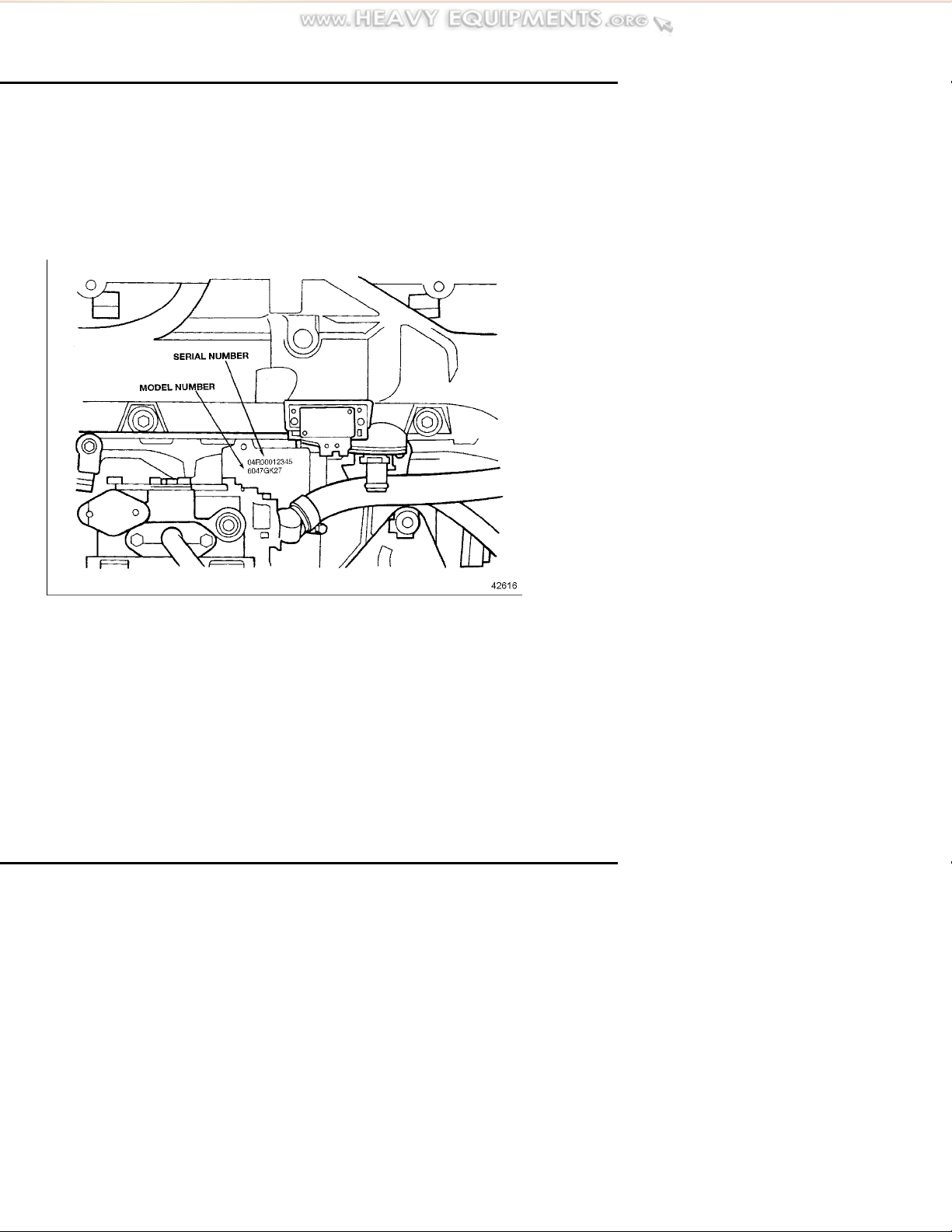
ENGINE MODEL AND SERIAL NUMBER DESIGNATION
ENGINE MODEL AND SERIAL NUMBER DESIGNATION
The engine serial number and model
number are laser etched on the
cylinder block on the left side just
the cast- in Detroit Diesel logo (as
viewed from the flywheel end).
SeeFigure1
below the intake manifold and above
Figure 1 Location of Engine Serial and Model Numbers
12 All information subject to change without notice. (Rev. 01/ 04)
6SE550 0401 Copyright © 2004 DETROIT DIE
SEL CORPORATION
SERIES 50 OPERATOR'S GUIDE
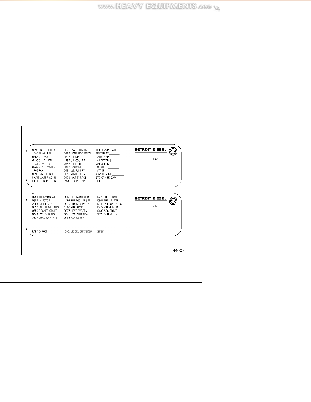
Option Labels
Computerized en gin e option labels
are attached to the valve rocker
cover. These labels contain the engine
serial number and model number
and, in addition, list any optional
equipment used on the engine.
Labels also include required tune-up
information (injection timin g, valve
lash, maximum no-load rpm, etc.).
With any order for parts, the engine
model and serial num ber m ust be
given. If a type number is shown
on the option label covering the
equipment required, this number
should also be included on the parts
order. See Figure 2.
Transmissions and power take-o ffs
generally carry their own name
plates. The model a n d serial number
information on these plates is
useful when ordering parts for these
assemblies.
Figure 2 Typical Option Labels
All information subject to change without not ice. (Rev. 01/ 04) 13
6SE550 0401 Copyright © 2004 DETROIT DIE
SEL CORPORATION
ENGINE MODEL AND SERIAL NUMBER DESIGNATION
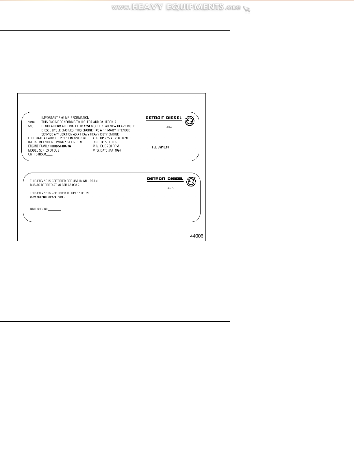
Certification Labels
If required, a certification label is
attached to the valve rocker cover.
This label certifi es that the engine
conforms to federal and certain state
emissions regulations for its particular
application. It also gives the operating
conditions under which certification
was made. See Figure 3.
Figure 3 Typical Engine Certification Labels
14 All information subject to change without notice. (Rev. 01/ 04)
6SE550 0401 Copyright © 2004 DETROIT DIE
SEL CORPORATION
SERIES 50 OPERATOR'S GUIDE
OPERATING INSTRUCTIONS FOR A FIRST TIME START
When preparing to start a new or newly
overhauled engine which has been in
storage, perform a ll of the operations
listed below. Failure to follow these
instructions may result in serious
engine damage. Before a routine start,
see the “Daily” checks for your engine
in the MAINTENANCE section.
To avoid injury when working
near or on an operating engine,
remove loose items of clothing,
jewelry, tie back or contain long
hair that could be caught in any
moving part causing injury.
System Checks
Diesel engine exhaust and some
of its constituents are known to
the State of California to cause
cancer, birth defects, and other
reproductive harm.
Always start and operate an
engine in a well ventilated
area.
If operating an engine in
an enclosed area, vent the
exhaust to the outside.
Do not modify or tamper
with the exhaust system or
emission control system.
Perform the following system checks
before starting for the first time.
Cooling System Checks
Check the cooling system as follows:
1. Make sure all drain cocks in
the cooling system are installed
(drain cocks are often removed
for shipping) and are closed
tightly.
2. Remove the radiator pressure
control cap and fill with genuine
Detroit Diesel Power Cool
antifreeze or an equivalent quality
ethylene glycol or propylene
glycol-base antifreeze solution
in the required concentration.
In extremely hot environments,
properly inhibited water may
be used in the summer. Keep
the coolant level at the bo ttom
of the fill er neck to allow for
All information subject to change without not ice. (Rev. 01/ 04) 15
6SE550 0401 Copyright © 2004 DETROIT DIE
SEL CORPORATION
OPERATING INSTRUCTIONS FOR A FIRST TIME START
expansion of the coolant. For
more detailed reco mmendations,
refer to the How to Select Coolant
section in this guide.
3. Entrapped air m ust be purged
after filling the cool ing system.
To do this, allow the engine to
warm up with the pressure cap
removed. With the transmission
in neutral, increase engine speed
above 1,000 rpm and add coolant
to the radiator as required.
4. Check to make sure the front
of the radiator and air-to -air
charge cooler (if equipped) are
unblocked and free of debris.
Lubrication System C hecks
The lubricating oil film on the rotating
parts and bearings of a new or newly
overhauled engine, or one which has
been in storage for six months or
more, may be insufficient when the
engine is started for the first time.
NOTICE:
Insufficient lubrication at startup can
cause serious damage to engine
components.
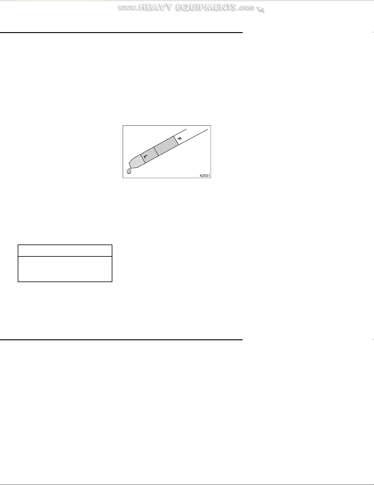
To insure an immediate flow of
oil to all bearing surfaces at initial
engine startup, the engine lubrication
system should be charged with a
commercially available pressure
pre-lubricator. If this is impractical,
rocker covers should be removed and
clean lubricating oil should be poured
over the rocker arms. The oil should
be the same weight and viscosity
as that used in the crankcase. After
pre-lubricating, add additional oil to
bring the level to the proper mark on
the dipstick. See Figure 4.
Figure 4 Check Lube Oil Level
Before Starting
For lubricant recomm endation ,
refer to the How to Select Lubricating
Oil section in this guide.
Extended Storage — An engine
in storage for an extended period
of time (over winter, for example)
may accumulate water in the oil
pan through normal condensation of
moisture (always present in the air)
on the cold, internal surfaces of the
engine. Lube oil diluted by water
cannot provide adequate bearing
protection at engine startup. For this
reason, Detroit Diesel recommends
16 All information subject to change without notice. (Rev. 01/ 04)
6SE550 0401 Copyright © 2004 DETROIT DIE
SEL CORPORATION

SERIES 50 OPERATOR'S GUIDE
replacing the engine lubricating oil
and filters after extended storage.
NOTICE:
Failure to eliminate water-diluted
lubricating oil may lead to serious
engine damage at startup.
Fuel System Checks
Fill the tanks with the recommended
fuel. Keeping tanks full reduces water
condensation and helps keep fuel
cool, which is important to engine
performance. Full tanks also reduce
the chance for microbe (black slime)
growth. For fuel recommendations,
refer to the How to Select Fuel Oil
section in this guide. Make sure the
fuel shutoff valve (if used) is open.
To insure prompt starting and even
running, the fuel system must
be primed if air has entered the fuel
system. Priming is done by connecting
a manual or electric priming pump
to the secondary fuel filter adaptor.
Authorized Detroit Diesel service
outlets are properly eq uip ped and have
the trained technicians to perform this
service.
NOTICE:
Prolonged use of the starting motor
andenginefuelpumptoprimethe
fuel system can result in damage to
the starter, fuel pump and injectors
and may cause erratic engine
operation due to the amount of air
in the line s and filters from the fuel
supply tank to the cylinder head.
Engines equipped with starting
devices dependent on compressed
air or gas reservoirs should always
be primed before initial startup.
Otherwise, reserve pressure can
be exhausted and injectors may be
damaged from lack of lubrication
and cooling.
Under no circumstances should
a starting aid such as ether be
used to run the engine until the
fuel system is primed. Injector
damage will result if this method
is used. The heat generated by the
external fuel source will cause the
injector tips to be damaged when
the fuel cools them. The injector
plunger and bushing can be scored
from running without lubrication.
Priming is not normally required if
the filter elements are filled with clean
fuel when installed and the manifolds
are not drained of fuel.
All information subject to change without not ice. (Rev. 01/ 04) 17
6SE550 0401 Copyright © 2004 DETROIT DIE
SEL CORPORATION

OPERATING INSTRUCTIONS FOR A FIRST TIME START
If the engine is equipped with a
fuel/water separator, drain off any
water that has accumulated. Water
in fuel can seriously affect engine
performance and may cause engine
damage. Detroit Diesel recommends
installation of a fuel/water separator
wherever water contamina tio n is a
concern.
Other Checks
Make sure the transmission is
filled to the proper level with the
fluid recommended by the gear
manufacturer. Do not ov erfill.
Make sure cable connections to
the storage batteries are clean and
tight. Check the hydrometer “eye” of
maintenance-free batteries for charge.
SeeFigure5.
Check drive belts to m ake sure they
are in good condition (not cracked,
torn, worn or glazed) and are properly
adjusted.
If lead-acid or low-maintenance
batteries are used, make sure battery
electrolyte level is normal.
Check the turbocharger for signs of
oil or exhaust leaks. Leaks should be
corrected before starting the engine.
Check engine mounting bolts for
tightness. Bolts should be retightened,
if necessary.
Starting the Engine
Before starting the engine the first
time, refer to the System Checks
section and perform the operations
listed.
NOTICE:
The turbocharger may be seriously
damaged if the engine is cranked
with the air shutdown in the closed
position.
If the engine has an emergency manual
or automatic shutdown system, make
sure the control is set in th e open
position before starting.
Figure 5 Check “Eye” of
Maintenance-Free
Batteries
18 All information subject to change without notice. (Rev. 01/ 04)
6SE550 0401 Copyright © 2004 DETROIT DIE
Theenginemayrequiretheuseofa
cold weather star ting aid if the ambient
temperature is below 40
F(4 C).
SEL CORPORATION

To avoid injury from flames,
explosion, and toxicants when
using ether, the following
precautions must be taken:
SERIES 50 OPERATOR'S GUIDE
warning lights. If everything is
OK, both lights will go out in
approximately five seconds.
Start the engine after the lights go
out. If starting a vehicle, start the
engine with foot off the foot pedal.
Do not smoke when servicing
ether system.
Work in well-ventilated area.
Do not work near open
flames, pilot flames (gas or
oil heaters), or sparks.
Do not weld or carry an open
flame near the ether system if
you smell ether or otherwise
suspect a leak.
Initial Engine Start
To start a Series 50 engine, make sure
the transmission is in neutral and turn
the ignition key on.
You will notice t hat both t he yellow
Check Engin Light (CEL) and the red
Stop Engine Light (SEL) will come
on.
This is the result of theDetroit
Diesel Electronic Control (DDEC
®
)
computer diagnosing the system
to ensure everything is functional,
including the light bulbs for the
NOTICE:
If the operating lights stay on,
consult with DDC Technical Service.
Operating the engine under these
circumstances may result in engine
damage.
Electric Starter — Start an engine
equipped with an electric starting
motor as follows:
1. With foot OFF the foot pedal,
press the starter switch firmly.
NOTICE:
To prevent serious starting motor
damage, d o not press the starter
switch again after the engine has
started.
2. If the engine fails to start within
15 seconds, release the starter
switch and allow the starter to
cool for 15 seconds before trying
again. If the engine fails to start
after four attempts, an inspection
should be m a de to determine the
cause.
All information subject to change without not ice. (Rev. 01/ 04) 19
6SE550 0401 Copyright © 2004 DETROIT DIE
SEL CORPORATION

OPERATING INSTRUCTIONS FOR A FIRST TIME START
Air Starter — Because of the limited
volume of most compressed air
storage tanks and the relatively short
duration of the cranking cycle, it is
important to make sure the engine is
ready to start before acti vati ng the air
starter. Start an en gin e equipped with
an air starter as follows:
1. Check the pressure in the air
storage tank. If necessary, add
air to b ri ng the pressure up to at
least the recommended minimum
for starting.
2. With foot OFF the foot pedal,
press the starter button firmly and
hold until the engine starts.
Running the Engine
While the engine is operating, monitor
the battery charge indicator light,
the oil pressure and avoid excessive
idling.
operating pressure should be higher. If
oil pressure does not fall within these
guidelines, it should be checked with
a manual gage.
To avoid injury from hot oil, do
not operate the engine with the
rocker cover(s) removed.
Warm-up
Run the engine at part throttle for
about five minutes to allow it to warm
up before applying a loa d.
Inspection
While the engine is idling, inspect the
transmission, check for fluid leaks,
check the crankcase and turbocharger.
Oil Pressure
Observe the oil pressure gage
immediately after starting the engine.
A good indicator that all m oving parts
are getting lubrication is when the
oil pressure gage registers pressure
(5 psi or 35 kPa at idle speed). If
no pressure is indicated within 10
is idling, check the automatic
transmission (if equipp e d) for proper
oil level and add oil as required.
Fluid Leaks – Lo ok for coolant,
fuel or lubricating oil leaks. If any
are found, shut down the engine
immediately and have the leaks
repaired after the engine has cooled.
to 15 seconds, stop the engine and
check the lubrication system. The
pressure should not drop below 28 psi
or 193 kPa at 1800 rpm, an d normal
Transmission – While the engine
20 All information subject to change without notice. (Rev. 01/ 04)
6SE550 0401 Copyright © 2004 DETROIT DIE
SEL CORPORATION

SERIES 50 OPERATOR'S GUIDE
Crankcase – Iftheengineoilwas
replaced, stop the engine after normal
operating temperature has been
reached. Allow the oil to drain
back into the crankcase for about
twenty minutes, then check the oil
level. If necessary, add oil to bring
the level to the proper mark on the
dipstick. Use only the heavy-duty oils
recommended. Refer to the How to
Select Lubricating Oil section in this
guide.
Turbocharger – Makeavisual
inspection of the turb ocharger for
oil leaks, exhaust leaks, excessive
noise or vibration. Stop the engine
immediately if a leak or unusual noise
or vibration is noted. Do not restart
the engine until the cause of the
concern has been investigated and
corrected. Autho rized Detroit Diesel
service outlets are properly equipped
to perform this service.
sludge in the engine. When prolonged
idling is necessary, maintain at least
850 rpm spring/summer and 1200 rpm
fall/winter.
Stopping the Engine
Stop an engine under normal operating
conditions as follows:
1. Reduce engine speed to idle and
put all shift levers in the n e utr al
position.
NOTICE:
Stopping a turbocha rged engine
immediately after high-speed
operation without allowing a
sufficient cool-down peri od may
cause damage to the turbocharger,
as it will continue to turn without an
oil supply to the bearings.
Avoid Unnecessary Idling
Whenever possible, avoid unnecessary
idling.
During long engine idling periods
with the transmission in neutral, the
engine coolant temperature may fall
2. Allow the engine to run between
idle and 1000 rpm with no load
for four or five minutes. This
allows the engine to cool and
permits the turbo charger to slow
down. After four or five minutes,
shut down th e engine.
below the normal operating range.
The incomplete combustion of fuel
in a cold engine will cause crankcase
oil dilution, formation of lacquer or
gummy deposits on the valves, pistons,
and rings, and rapid accumulation of
All information subject to change without not ice. (Rev. 01/ 04) 21
6SE550 0401 Copyright © 2004 DETROIT DIE
SEL CORPORATION

OPERATING INSTRUCTIONS FOR A FIRST TIME START
Emergency Jump Starting
The DDEC IV system operates on
12 or 24 volts DC. If an engine with
an electric starting motor requires
emergency jump starting, do not
exceed 32 volts DC.
NOTICE:
Jump starting with voltages greater
than those indicated or reversing
battery polarity may damage the
Electronic Control Module.
To avoid injury from battery
explosion when jump starting the
engine, do not attach the cable
end to the negative terminal of
the disabled battery.
and in the proper sequence (negative
to negative g ro und last).
To avoid injury from battery
explosion or contact with battery
acid, w ork in a well-ventilated
area, wear pr otective clothing,
and avoid sparks or flames
near th e battery. Always
establish correct polarity before
connecting cables to the battery
or battery circuit. If you come in
contact with battery acid:
Flush your skin with water.
Applybakingsodaorlimeto
help neutralize the acid.
Flush your eyes with water.
Get medical attention
immediately.
NOTICE:
Failure to connect jumper cables
in the proper sequence can result
in alternator and/or equipment
damage.
Before att e mpting to jump start the
engine, make sure the jumper cables
are connected properly (positive to
positive, negative to negative ground)
22 All information subject to change without notice. (Rev. 01/ 04)
6SE550 0401 Copyright © 2004 DETROIT DIE
SEL CORPORATION

DDEC IV SYSTEM
SERIES 50 OPERATOR'S GUIDE
The DDEC sytem's engine-mounted
Electronic Control Module (ECM)
includes control logic to provide
overall engine m anagement. The
ECM co ntinuo usly performs
self-diagnostic checks and monitors
other system components. System
diagnostic checks are made at
ignition-on and continue throughout
all engine-operating modes.
Detroit Diesel Series 50 engines
equipped with DDEC IV are identified
by the letter “K” in the sixth position
of the model number. Example:
6047GK27.
The DDEC engine is equipped
with an electronically controlled
fuel injection system. There are no
control racks or mechanical linkages
to adjust. This system not only helps
to improve fuel economy and vehicle
performance, it also helps to reduce
cold starting time and increase initial
idle speed for fast engine wa rm-up
and virtual elimination of cold smoke.
The DDEC engine has no
mechanical governor. Engine
horsepower, torque, idle, and engine
speed are contained in the internal
electronics. Therefore, there are
no mechanical governor spring
adjustments for idle and high-speed
control.
There is no need for a throttle delay.
Emission control is performed through
the electronic control module (ECM).
The Electronic Foot Pedal Assembly
(EFPA) eliminates the need for any
throttle linkage.
DDEC Features
DDEC offers a variety of options
designed to warn the operator of an
engine malfunction. Options can
range from the CEL and SEL panel
lightstoautomaticreductioninengine
power followed by automatic engine
shutdown.
The pow er-down/shutdown option
may be activated by a low coolant
level, low oil pressure or high engine
oil or coolant temperature.
The DDEC engine has the ability to
perform diagnostics for self-checks
and continuous monitoring of other
system components. Depending
on the application, DDEC can also
monitor oil temperature, coolant
temperature, oil pressure, fuel
pressure, coolant level and remote
sensors (if used). This diagnostic
system is connected to the CEL and
the SEL to provide a visual warning
of a system malfunction.
All information subject to change without not ice. (Rev. 01/ 04) 23
6SE550 0401 Copyright © 2004 DETROIT DIE
SEL CORPORATION

DDEC IV SYSTEM
Engine Protection
The DDE C engine protection
system monitors all engine sensors
and electronic components, and
recognizes system malfunctions. If
a critical fault is detected, the CEL
and SEL illumin ate. The malfunction
codes are logged into the ECM's
memory.
The standard parameters which are
monitored for engine protection
are: low coolant level, high coolant
temperature, low oil pressure, and
high oil temperature
This system features a 30-second,
stepped-power shutdown sequence
or an immediate speed reduction
without shutdown in the event a major
engine malfunction occurs, such as
low oil pressure, high oil or coolant
temperature, or low coolant level.
NOTICE:
Engines equipped w ith the
power-down/shutdown option have
a system override button or switch
to allow engine operation for a
short period of time. Using the
override button so the engine does
not shutdown in 30 seconds but
operates for an extended period
may result in engine damage
Idle Shutdown Timer
The DDEC engine may also have
an optional 1 to 100 minute idle
shutdown system. The purpose of
this system is to conserve fuel by
eliminating excessive idling and to
allow for a turbocharger cool-down
period. To activate the shutdown, the
transmission must be in neutral with
the vehicle parking brakes set and the
engine in idle or fast-idle mode.
Cruise Control
To avoid injury from engine
shutdown in an unsafe situation,
ensure the operator knows how
to override the stop engine
condition on a DDEC-equipped
unit.
Cruise Control is available with
any DDEC engine. Cruise Control
maintains a set vehicle or engine
speed settin g. The driver/operator
has switches to set, activate and
deactivate the system . See Figure 6.
A slight pressure on the brake or
clutch deactivates the system, as well.
The minimum speed at which cruise
control can be used is programmable.
24 All information subject to change without notice. (Rev. 01/ 04)
6SE550 0401 Copyright © 2004 DETROIT DIE
SEL CORPORATION

Figure 6 Typical Cruise Control
Switches
SERIES 50 OPERATOR'S GUIDE
To avoid injury from the loss of
vehicle control, do not use cruise
control under these conditions:
When it is not possible to
keep the vehicle at a con stant
speed (on winding roads, in
heavy traffic, in traffic that
varies in speed, etc.).
On slippery roads
(wet pavement, ice-or
snow-covered roads, loose
gravel, etc.).
Cruise Control may a lso be
programmed to permit fast idle
using the cruise control switches.
With the engine at normal idle,
transmission in neutral and service
brakes on, turn on the cruise control
“ON/OFF” switch, and use the
“Resume” switch. The engine rpm
should increase to a pre-defined
When descending a hill with
cruise control OFF, do not allow
the eng ine to exceed 2,500 rpm
under any conditions. Failure to
observe this precaution can result
in overspeeding and serious engine
damage.
NOTICE:
speed. The engine rpm can be raised
or lowered from this point using the
“Set” and “Resume” switches.
Cruise Control will main tain the set
speed under normal road and load
conditions.
Cruise Control cannot limit vehicle
speeds on down grades if available
engine braking effort is exceeded, nor
can it maintain speed on upgrades if
power requirements exceed engine
power capability.
All information subject to change without not ice. (Rev. 01/ 04) 25
6SE550 0401 Copyright © 2004 DETROIT DIE
SEL CORPORATION

DDEC IV SYSTEM
When the Cruise Control switch
is in the O N position, cruise
control is engaged by momentarily
contacting the “Set/Coast” switch
to the ON position. Holding the
switch in the ON position allows the
vehicle to slow to a lower speed.
Toggling t he switch will result in a
one mile-per-hour (1.6 kph) decrease
in vehicle speed. If cruise control
has been disabled, toggling the
“Resume/Accel” switch restores the
vehicle to the previously set cruise
speed.
Using either the brake or the clutch
will disable cruise control.
To avoid injury from loss of
vehicle control, do not activate
the Engine Brake system under
the following conditions:
On wet or slippery pavement,
unless the vehicle is equipped
with ABS (anti-lock braking
system) and you have had
prior experience driving
under these conditions.
When driving without a trailer
(bobtailing) or pulling and
empty trailer.
Engine Brakes
Engine brakes are enabled by an
ON/OFF switch mounted on the dash.
A separate intensity switch is used to
select low, medium or high braking
power. Th e engine brakes will only
operate when the electronic foot pedal
assembly (EFPA) is fully released.
Disengaging the clutch will prevent
the engine brakes from operating.
Ifthetractordrivewheels
begin to lock or there is
fishtail motion after the
EngineBrakeisactivated.
Deactivate the brake system
immediately, if this occurs.
Failure to observe these
precautions may result in
loss of vehicle control and/or
personal injury.
Engine b rakes will supply braking
power even when in cruise control.
The electronic control module (ECM)
will control the amount of engine
braking with respect to the cruise
control set speed. The maximum
amount of braking (low, medium, high)
is selected with the dash switches.
26 All information subject to change without notice. (Rev. 01/ 04)
6SE550 0401 Copyright © 2004 DETROIT DIE
SEL CORPORATION

SERIES 50 OPERATOR'S GUIDE
Data Recording Capability
DDEC Reports is a data recording
capability that is standard on all DDEC
IV engines. DDEC Reports contains
information on driver activities,
engine performance and critical
incidence reporting. The information
can be extracted with Detroit Diesel
Diagnostic Link
®
2.1 (DDDL 2.1)
or later software. To perform the
extraction, at least a 486 computer
with a 16-MB RAM is required.
DDEC IV Operation
NOTE:
This engine is equipped with DDEC
software. This software generally
assures optimal en gine performance.
The installation of software upgrades
may cause minor changes in features
and engine performance.
Since the DDEC system is electronic,
a battery is required to operate the
computer. The system operates at 12
or 24 volts. However, in the event of a
power supply malfunction, the system
will continue to operate at reduced
voltage. When this occurs, the CEL
will come on.
The engine will only operate at
reduced rpm until the battery voltage
reaches a point where t he ECM w ill
no longer function and the engine
shuts down.
Should the CEL come on for any
reason, the vehicle can still be
operated and the driver can proceed
to the required destination. This
conditionshouldbereportedtoan
authorized Detroit Diesel di stributor
or dealer.
NOTICE:
When the SEL comes on, the
computer has detected a major
malfunction in the engine that
requires immediate attention. It is
the operator's responsibility to
shut down the engine to avoid
serious damage.
The engine can be configured to
give a warning only, to ramp down
(reduce power) or to shut down.
Ramp down will red uce engine rpm
to a pre-determined speed, but will
not shut down the engin e . With
the 30-second shutdown option, the
engine will begin a 30-second, stepped
power-down sequence until it shuts
down completely.
Stop Engine Override can be supplied
in case the vehicle is to operate in a
critical location.
NOTE:
The Stop Engine Override switch and
the Diagnostic Request switch are the
same.
All information subject to change without not ice. (Rev. 01/ 04) 27
6SE550 0401 Copyright © 2004 DETROIT DIE
SEL CORPORATION

DDEC IV SYSTEM
In this situation the operator may
elect to override the automatic stop
engine sequence by pressing the Stop
Engine Override switch every 15 to 20
seconds to prevent engine shutdown
from occurring.
NOTE:
For some applications, holding down
the Stop Engine Override switch will
not prevent the engine shutdown
sequence. You must continue to reset
the automatic shutdown system by
pressing the S top Engi ne Overrid e
switch at intervals of approximately 15
to 20 seconds.
It takes 30 seconds from the time the
automatic shutdown sequence begins
until engine shutdown. Therefore,
the operator must press the override
switch just prior to engine shutdown
and continue to do so until the vehicle
can be b ro ught to a stop in a safe
location.
Immediate Speed Reduction
Option
The immediate speed reduction option
will bring engine rpm back to a
predetermined speed, but will not shut
down the engine.
Stop Engine Light
The conditions that will cause theSEL
to come on are:
High coolant temperature
Loss of coolant
High oil temperature
Low oil pressure
Auxiliary shutdown
It is important to point out that
whenever the CEL or the SEL
comes on, the DDEC computer will
determine wh e re the problem is and
will then store this information in its
memory.
If the malfunction is intermittent, the
lights will come on and go off as the
computer senses the changing engine
condition.
Diagnostic Data Reader
The Diagnostic Data Reader (DD R)
is a special diagnostic tool that can
be plugged into the engine computer
memory to extract information
related to the cau se of the problem.
See Figure 7.
The engine should not be restarted
after it has been shut down by the
engine protection system, unless
the problem has been located and
corrected.
28 All information subject to change without notice. (Rev. 01/ 04)
6SE550 0401 Copyright © 2004 DETROIT DIE
SEL CORPORATION

Figure 7 Diagnostic Data Reader
J 38500
Once the malfunction has been
corrected, the DDEC system will
return the engine to normal operation.
The DDR can distinguish between
codes now active and th ose stored in
the ECM memory (inactive).
SERIES 50 OPERATOR'S GUIDE
The malfunction code recorded in the
computer memory will remain until it
is erased by a technician.
The malfunction code can also
be obtained by the operator. A
“Diagnostic Request” switch is
provided which, when pressed, will
cause the “Check Engine” light (CEL)
to flash a code number. It will, for
example, flash twice. . . pause . . .
flashonce...pause.Inotherwords,a
code 21. Code 21 indicates the throttle
position sensor input voltage is high.
See Figure 8.
NOTE:
A code 25 (two flashes followed by
5 flashes) indicates all systems are
working satisfactorily.
Figure 8 SEL/CEL Flashing Code Examples
All information subject to change without not ice. (Rev. 01/ 04) 29
6SE550 0401 Copyright © 2004 DETROIT DIE
SEL CORPORATION

DDEC IV SYSTEM
Active Codes – The active codes will
be flashed on the SEL in the order of
most recent to least recent occurrence
based on engine hours. If there are no
active codes, a code 25 will be flashed.
Inactive Codes – The inactive codes
willbeflashedontheCELinthe
order of most recent to least recent
occurrence based on engine hours. If
there are no inactive codes, a code 25
will be flashed.
Only One Light Flashes at a Time –
Only one light will be flashing codes
at any time. When code flashing is
initiated, the active cod es (or code
25) will be flashed on the SEL. Then
the inactive codes (or code 25) will
be flashed on the CEL. When all the
inactive codes (or code 25) have been
flashed, the process of flashing all
the active codes followed by all the
inactive codes will repeat until the
conditions for code flashing are no
longer satisfied.
To Read Codes: Use the diagnostic
data reader (DDR) or depress and hold
the diagn ostic request switch with
the ignition ON and the engine AT
IDLE or NOT RUNNING. Press and
hold the switc h. Active codes will be
flashed on the SEL first, followed by
inactive codes flashed on the CEL.
Diagnostic Code List
Diagnostic codes are listed in the next
several pages.
To avoid injury from engine
shutdown in an unsafe situation,
ensure the operator knows how
to override the stop engine
condition on a DDEC-equipped
unit.
To avoid injury from loss of
vehicle/vessel contr ol, the
operator of a DDEC equipped
engine must not attempt to use
or read the Diagnostic Data
Reader when the vehicle/vessel
is moving.
The codes will continue to flash and
repeat as long as the diagnostic request
switchisheldintheONpositionwith
the ignition on.
30 All information subject to change without notice. (Rev. 01/ 04)
6SE550 0401 Copyright © 2004 DETROIT DIE
SEL CORPORATION

SERIES 50 OPERATOR'S GUIDE
Flash
Code
Description
11 Variable Speed Governor Sensor Voltage Low
11 Variable Speed Governor Switch System Not Responding
12 Variable Speed Governor Sensor Voltage High
13 Coolant Level Sensor Input Voltage Low
13 Add Coolant L evel Sensor Input Voltage Low
14 Intercooler Coolant Temperature Sensor Input Voltage High
14 Coolant Temperature Sensor Input Voltage High
14 Oil Temperature Sensor Input Voltage High
15 Intercooler Coolant Temperature Sensor Input Voltage Low
15 Coolant Temperature Sensor Input Voltage Low
15 Oil Temperature Sensor Input Voltage Low
16 Coolant Level Sensor Input Voltage High
16 Add Coolant Le vel Sensor Input Voltage High
17 Throttle Plate Position Sensor Input Voltage High
17 Blower Bypass Position Input Voltage High
17 Relative Humidity Sensor Circuit Failed High
18 Throttle Plate Position Sensor Input Voltage Low
18 Blower Bypass Position Input Voltage Low
18 Relative Humidity Sensor Circuit Failed Low
21 Throttle Position Sensor Input Voltage High
22 Throttle Position Sensor Input Voltage Low
23 Fuel Temperature Sensor Input Voltage High
23 Oxygen Content Circuit Input Voltage High
24 Fuel Temperature S ensor Input Voltage Low
24 Oxygen Content Circuit Input Voltage Low
25 Reserved for ‘‘No Codes"
26 Aux. Shutdown #1 Active
26 Aux. Shutdown #2 Active
27 Intake Manifold Temperature Sensor Input Voltage High
All information subject to change without not ice. (Rev. 01/ 04) 31
6SE550 0401 Copyright © 2004 DETROIT DIE
SEL CORPORATION

DDEC IV SYSTEM
Flash
Code
27 Ambient Air Temperature Sensor Input Voltage High
27 Air Temperature Sensor Input Voltage High
28 Intake Manifold Temperature Sensor Input Voltage Low
28 Ambient Air Temperature Sensor Input Voltage Low
28 Air Temperature Sensor Input Voltage Low
29 TCI Temperature Circuit Failed Low
Turbo Compressor Temperature Out Sensor Input Voltage
29
Low
31 Aux. Output #3 or #4 Open Circuit (High Side)
31 Aux. Output #3 or #4 Short To Ground (High Side)
31 Aux. Output #3 or #4 Mechanical System Failure
32 SEL or CEL Short to Battery (+)
32 SEL or CEL O pen Circuit
33 Turbo Bo ost Pressure Sensor Input Voltage Hig h
34 Turbo Boost Pressure Sensor Input Voltage Low
35 High Range Oil Pressure Sensor Input Voltage High
35 Oil Pressure Sensor Input Voltage Low
36 High Range Oil Pressure Sensor Input Voltage High
36 Oil Pressure Sensor Input Voltage Low
37 High Range Fuel P ressure Sensor Input Voltage High
37 Fuel Restriction or Fuel Pressure Sensor Input Voltage High
38 High Range Fuel Pressure Sensor Input Voltage Low
38 Fuel Restriction or Fuel Pressure Sensor Input Voltage Low
39 EGR Leak — Boo st Power
39 EGR Leak — Boost Jake
39 EGR Valve Not Re sponding
39 VNT Vanes No t Responding — Boost Power
39 VNT Vanes at Max — Jake
39 VNT Vanes Not Responding — Boost Jake
Description
32 All information subject to change without notice. (Rev. 01/ 04)
6SE550 0401 Copyright © 2004 DETROIT DIE
SEL CORPORATION

SERIES 50 OPERATOR'S GUIDE
Flash
Code
Description
39 EGR Flow too Low
39 VNT Vanes Not Responding — EG R
41 Too Many SRS (missing TRS)
42 Too few SRS (missing SRS)
43 Coolant Level Low
44 Intercooler Coolant Temperature High
44 Engine Derate Due to Intake Manifold Temp or Coolant Temp
Intake Manifold Temp, Coolant Temp, Air Inlet Temp, or Oil
44
Tem p Hi gh
45 High Range Oil Pressure Low
45 Oil Pressure Low
46 ECM Battery Voltage Low
46 RTCBackupBatteryVoltageLow
46 Sensor Supply Voltage Low
High Range F uel Pressure, Fuel Pressure, Turbo Boost
47
Pressure, Air Inlet Pressure, or Injection Control Pressure
High
High Range Fuel Pressure, Fuel Pressure, Air Inlet Pressure,
48
or Injection Control Pressure Low
48 TCI Temperature Below Range
48 Turbo Compressor Temperature Out High
48 EGR Differential Pressure or EGR Temperature Low
49 TCI Temperature Above Range
49 Turbo Compressor Out Temperature High
49 Engine Derate Due to TCO Temperature
51 TCI Temperature Circuit F ailed High
Turbo Compressor Out Temperature Sensor Input Voltage
51
High
52 A/D Conversion Fail
53 Nonvolatile Checksum Incorrect
All information subject to change without not ice. (Rev. 01/ 04) 33
6SE550 0401 Copyright © 2004 DETROIT DIE
SEL CORPORATION

DDEC IV SYSTEM
Flash
Code
53 EEPROM Write Error
53 OutofCalibration
54 Vehicle Speed Sensor Fault
55 Missing information from another ECU
J1939 Data Link, Proprietary Data Li nk (Master), or
55
Proprietary Data Link (Receiver) Fault
56 J1587 Data Link or J1922 Data Link Fault
58 Torque Overload
61 Injector xxx Response Time Long
Aux. Output #1, #2, #5, #6, #7, or #8 Short to Battery
(+), Open Circuit, or Mechanical System Not R esp onding
62
Properly
PWM #1, #2, #3, or #4 Above Normal Range, Below Normal
63
Range, Short to Battery (+), or Open Circuit
64 Turbo Overspeed
64 Turbo Speed Sensor Input Failure — Abnormal Period
Throttle Plate Position Ab ove Normal Range, Below Normal
65
Range, Erratic, or No t Responding
65 Air Filter Restriction Sensor Voltage High or Low
66 Oil Filter Restriction Sensor Voltage High or Low
66 Engine Knock Le v el Above Normal Range
Engine Knock Level Sensor Input Voltage High, Low, or Not
66
Responding
67 High Range Coolant Pre ssure Sensor Input Voltage High
67 High Range Coolant Pressure Sensor Input Voltage Low
67 Air Inlet Pressure Senso r Input Voltage High or Low
67 Coolant Pressure Sensor Input Voltage High or Low
TPS Idle Validation Circuit Fault (open circuit or short to
68
ground)
71 Injector xxx Response Time Short
72 Vehicle Overspeed
Description
34 All information subject to change without notice. (Rev. 01/ 04)
6SE550 0401 Copyright © 2004 DETROIT DIE
SEL CORPORATION

SERIES 50 OPERATOR'S GUIDE
Flash
Code
Description
72 Vehicle O verspeed (Absolute)
72 Oxygen Content Too High or Too Low
73 AirFilterRestrictionHigh
73 Gas Valve Position Above or Below Normal Range
73 Gas Valve Position Input Voltage High or Low
73 Gas Metering Valve Not Responding
73 ESS Transmission Stuck in Gear
73 Transmission Neutral Switch Failure (ESS Transmission)
Aux Analog Input Data Erratic, Intermittent, or Incorrect
73
(ESS Transmission)
73 Aux Analog Input #1 Voltage High or Low (ESS Transmission)
74 Optimized Idle Safety Loop Short to Ground
74 Oil Filter Restriction High
75 ECM Battery Voltage High
75 RTC Backup Battery Voltage High
75 Sensor Supply Voltage High
76 Engine Overspeed With Engine Brake
Miscellaneous Faults – Refer to BASIC TROUBLESHOOT-
77
ING
78 Cruise Control/Adaptive Cruise Control Fault
Oil Level Sensor Input or Crankcase Pressure Sensor Input
81
Voltage High
81 Extended Crankcase Pressure Input Voltage Hig h
Injection Control Pressure or Exhaust Temperature Sensor
81
Input Voltage High
EGR Differential Pressure Sensor Circuit or EGR
81
Temperature Circuit Failed High
81 Timing Actuator Failed High or Low
Exhaust Port Temperature #1, #2, #3, #4, #5, #6, #7, #8, #9,
81
#10, #11, #12, #13, #14, #15 or #16 Sensor Voltage High
81 EGR Mass Flow Smart Sensor not Responding or Failed
All information subject to change without not ice. (Rev. 01/ 04) 35
6SE550 0401 Copyright © 2004 DETROIT DIE
SEL CORPORATION

DDEC IV SYSTEM
Flash
Code
Oil Level Sensor or Crankcase Pressure Sensor Input
82
Voltage Low
82 Extended Crankcase Pressure Input Voltage Low
Injection Control Pressure Sensor or Exhaust Temperature
82
Sensor Input Voltage Low
EGR Temperature Circuit or EGR Diffferential Pressure
82
Sensor Circuit Failed Low
Exhaust Port Temperature #1, #2, #3, #4, #5, #6, #7, #8, #9,
82
#10, #11, #12, #13, #14, #15 or #16 Sensor Voltage Low
82 EGR Temperature Smart Senso r not Responding or Failed
83 Oil Level, Pump Pressure, or Crankcase Pressure High
83 Extended Crankcase Pressure High
83 Exhaust Temperature High
83 EGR Differential Pressure or EGR Temperature High
83 Exhaust Port Temperature #1 — #16 Sensor Voltage High
84 Oil Level or Crankcase Pressure Low
84 Extended Crankcase Pressure Low
85 Engine Overspeed
85 Engine Overspee d Signal
Pump Pressure Sensor or Barometric Pressure Se nsor Input
86
Voltage High
Pump Pressure Sensorr or Barometric Pressure Sensor
87
Input Voltage Low
88 High Range Coolant Pressure or Coolant Pressure Low
89 Fuel Restriction High
89 Maintenance Alert Coolant Level Fault
Description
36 All information subject to change without notice. (Rev. 01/ 04)
6SE550 0401 Copyright © 2004 DETROIT DIE
SEL CORPORATION

DDEC IV ENGINE DRIVING TIPS
SERIES 50 OPERATOR'S GUIDE
Driving with an electronically
controlled engine feels different from
driving with a mechancially governed
engine.
Accelerating the Vehicle
Engine response versus pedal
movement may feel different from the
mechanical-governed engine you were
driving. The electronic foot pedal
assembly (EFPA) was designed to
communicate “percentage” foot pedal
travel to the engine's electronic control
module (ECM). The engine will
respond accordingly to the driver's
demand.
Another thro ttle or governor
characteristic you may need time to
get used to is the DDEC limiting
speed governor. This allows the driver
to command total en g ine response
between idle and rated speed, such
as accelerating at half throttle —
an advantage when driving under
slippery conditions.
Cruise Control
For added driver convenience and
comfort, DDEC IV also features a
cruise control option that works just
like the system in your car. It can
be operated in any gear above 1000
rpm or road speed faster than 20
mph (32 kph), up to the r ated engine
speed. And it can be programmed to
hold your road speed at or below the
maximum vehicle speed. The switch
to energize cruise control is usually
mounted on the instrument panel.
See Figure 9.
If you require wide-open throttle
engine response, either accelerating
or just plain pulling hard, the throttle
(EFPA) will have to be held to the
floor. To obtain 100% fueling at any
speed, the foot pedal will have to
be maintained at the fully depressed
position.
All information subject to change without not ice. (Rev. 01/ 04) 37
6SE550 0401 Copyright © 2004 DETROIT DIE
Figure 9 Typical Cruise Control
Switches
SEL CORPORATION

DDEC IV ENGINE DRIVING TIPS
Turn the switch ON to energize the
system. When you reach your road
speed, press the “Set” switch to
activate cruise control. The cruise
light will come on. To increase
road speed in one mile-per-hour
(1.6 kilometer-per-hour) increments,
press the “Resume/Accel” switch. To
reduce road speed, press and hold the
“Set/Coast” switch until the lower
speed is reached.
Cruise control is deactivated by
slightly depressing the service brakes,
clutch ped al, or trailer brake. The
“On/Off” switch will also d eactivate
cruise control.
Cruise control will maintain vehicle
speed even on up grades, unless power
requirements dem and a downshift.
And, of course, cruise control does
not limit your speed on dow n grades.
Most likely, cruise control will feel
stronger than driving with the foot
pedal because of the instantaneous and
wide-open throttle response. That's
why cruise control use is not suggested
during slippery driving conditions.
Usecruisecontrolafterdown
shifting on a hill to pull the hill.
Hitting the “Resume” switch (not
the “Set” switch) will keep the truck
accelerating in the lower gears up to
the rated engine speed.
Cruise control will disengage below
1100 rpm or 20 mph (32 kph) road
speed. When using cruise control,
if you want to pull the engine below
1100 rpm, remember to hold the
throttle pedal to the floor to keep the
engine pulling at wide-open throttle.
Realistically, the engine will pull to
about 1050 rpm.
Remember: The electronic data
programmed into th e ECM will
not allow you to hurt or overfuel
theengineatlowor“lug”engine
speeds. There is enough oil pressure
to withstand hard pulls at low engine
speeds.
38 All information subject to change without notice. (Rev. 01/ 04)
6SE550 0401 Copyright © 2004 DETROIT DIE
SEL CORPORATION

SERIES 50 OPERATOR'S GUIDE
Engine Brakes and Cruise
Control
If your engine is equipped with
both cruise control and engine brake
retarders, the engine retarders can
operate automatically while you
are in cruise control. If the cruise
control/engine brake function is turned
ON in the ECM (electronic control
module) programming, the engine
retarders will come on “low” when
your set road speed increases a few
miles-per-hour (kilometers per hour)
above your cruise set speed. If your
speed continues to increase, the ECM
will increase the engine retarders'
braking power progressively. When
the vehicle returns to the set cruise
speed, the engine retarders will “turn
off” until you need them.
For safety reasons, don't use cruise
control when it is not possible to keep
the vehicle at constant speed due to:
Winding roads
Heavy traffic
Shifting
Depending on your transmission
model, the gear split may vary from
500 to 300 rpm. The electronic
governor provides almost no overrun
capability; and, if the transmission
is downshifted too early, you will
experience a temporary loss of pulling
power until the en gine speed falls
below rated speed.
In general, when using a 7- or 9-speed
transmission, you should alway s
downshift between 1250 and 1300
rpm. This is true even on steep grades
with heav y loads. When using an
18-, 15- or 13-speed transmission,
youwillneedtodownshiftatan
rpm that allows “less than rated”
rpm before throttle application in the
next gear down. You may want to
limit engine speed to 1900 rpm in all
gears. The S eries 50 provides constant
horsepower from 1800 rpm through
2100 rpm, but fuel economy is not as
efficient above 1800 rpm.
Slippery pavement
Descending grades that call for
engine brake assistance.
For an explanation of the engine
brake retarder system and
recommendations for pro per
operation, refer to section ENGINE
BRAKE SYSTEM.
All information subject to change without not ice. (Rev. 01/ 04) 39
6SE550 0401 Copyright © 2004 DETROIT DIE
SEL CORPORATION

DDEC IV ENGINE DRIVING TIPS
If you decide to drive at lower rpm's
for improved fuel economy, don't let
different engine noises throw you
off guard. The Series 50 sounds
quiet at 1400 rpm, almost as if it
had quit pulling . Don't believe it!
If you had a boost gage to look at
while driving, you would notice
the turbocharger maintaining steady
intake manifold pressure, even as
rpm's fall. Depen ding on the air
intake arrangement, you may also
experience a “chuffing” sound as the
engine starts to pu ll hard at lower
rpm's. This is caused by the velocity
changes of the air flow w ithin the air
intake plumbing. Electronic engines
can actually deliver more fuel at lower
engine speeds than at rated speed.
Idling
The com m on belief that idling a diesel
engine causes no engine damage is
wrong. Idling produces sulfuric acid,
which breaks down the oil and eats
into bearings, rings, valve stems and
engine surfaces. If you must idle the
engine for cab heat or cooling, the
high idle function of the cruise control
switches should be used. An idle
speed of 1100 rpm should be enough
to provide cab heat in above 32
C) ambients.
F(0
Winter Fronts
Awinterfrontmaybeusedtoimprove
cab heating while idling, bu t it should
never cover more than 3/4 of the
grille while driving. Winter fronts
should only be used when the ambient
temperature remains below 10
(-12.2
C).
F
40 All information subject to change without notice. (Rev. 01/ 04)
6SE550 0401 Copyright © 2004 DETROIT DIE
SEL CORPORATION

ENGINE BRAKE SYSTEM
SERIES 50 OPERATOR'S GUIDE
Certain Series 50 v ehicle engines
are equipped with engine brakes,
commonly referred to as retarders.
Before operating the vehicle, you
must familiarize yourself with the
retarder system to obtain optimum
benefit from it. Engine brake control
systems may vary slightly, depending
on the engine brake configuration and
cab design. However, basic operator
controls are similar for all m odels.
Driver Control Switches
Vehicles with manual transmissions
allow t he driver to turn the engine
brake on and off and select a low,
medium or high level of braking. Two
types of switches are available.
Low/High Switch
The “Low” setting on this switch
activates three (3) brake cylinders,
supplying approximately 50% of
normal engine braking horsepower.
The “High” setting activates all six
(6) cylinders, providing full engine
braking horsepower.
about two-thirds engine braking
horsepower. The “High” setting
activates all six (6) cylinders,
providing full braking horsepower.
Clutch Pedal and Throttle
Position Controls
Engine brakes have two additional
controls, one activated by the position
of the clutch pedal and the other
activated by the position of the
throttle. These controls permit fully
automatic operation of the engine
braking system.
Low/Med/High Switch
The “Low” setting on this switch
activates two (2) brake cylinders,
yielding about one-third engine
braking horsepower. The “Medium”
activates four (4) cylinders, supplying
All information subject to change without not ice. (Rev. 01/ 04) 41
6SE550 0401 Copyright © 2004 DETROIT DIE
SEL CORPORATION

ENGINE BRAKE SYSTEM
Engine Brake Operation
NOTICE:
Proper operation of the engine brake
retarder system depends o n the free
flow of engine oil. To ensure positive
engine brake engagement when
required, allow the engine to warm
to normal operating temperature
before activating the engine brake
system.
The engine brake retarder system
depends on a full-pressure flow of
warm engine lubricating oil for proper
lubrication of moving parts and
optimum performance. That's why it's
important to allow the engine to reach
full operating temperature before
switching on the engine brake system.
Under normal driving conditions the
engine brake system is left in the ON
position. However, t his should change
if roads become wet or slippery.
After it is switched on, the engine
brake system is automatically
activated each time you remove
your feet completely from the clutch
pedal and throttle. The engine brake
automatically deactivates itself when
you depress the clutch pedal while
shifting gears.
To avoid injury from loss of
vehicle control, do not activate
the Engine Brake system under
the following conditions:
On wet or slippery pavement,
unless the vehicle is equipped
with ABS (anti-lock braking
system) and you have had
prior experience driving
under these conditions.
When driving without a trailer
(bobtailing) or pulling and
empty trailer.
Ifthetractordrivewheels
begin to lock or there is
fishtail motion after the
EngineBrakeisactivated.
Deactivate the brake system
immediately, if this occurs.
Failure to observe these
precautions may result in
loss of vehicle control and/or
personal injury.
NOTE:
Some systems may be programmed
to activate themselves only when the
brake pedal is depressed, so read your
vehicle owner's manual thoroughly to
find out if you have this option.
42 All information subject to change without notice. (Rev. 01/ 04)
6SE550 0401 Copyright © 2004 DETROIT DIE
SEL CORPORATION

SERIES 50 OPERATOR'S GUIDE
NOTICE:
Do not attempt to “double clutch”
the transmission while the engine
brake system is turned on. Shifting
gears without depressing the clutch
or using the engine brake to reduce
engine rpm may result in seriou s
powertrain damage.
Anti-Lock Braking
Systems
Vehicles equipped with A BS
(anti-lock braking systems) have
the ability to turn the engine brake
retarder OFF if a wheel-slip condition
is detected. The engine brake will
automatically turn itself ON once
the wheel slip is no longer detected.
The DDEC system will deactivate
theenginebrakesystemwhenthe
engine speed falls below 1000 rpm
or when the vehicle slows down to a
pre-set speed, depending on DDEC
programming. This prevents stalling
the engine. Engine brakes can also
be used with vehicle cruise control
TURNED ON.
DrivingonFlat,Dry
Pavement
Use the following guidelines when
driving on flat, dry pavement:
1. If driving on f lat, dry, o pen
stretches w it h a light load and
greater slowing power is not
required, place the progressive
brakingswitchintheLOW
position.
2. If you find you are still u sing the
service brakes, move the switch
to a higher position until you do
not need to use the service brakes
to slow the vehicle down.
3. If you are carrying a heavier load
and road traction is good, move
the progressive braking switch to
the “High” position.
4. Check your progressive braking
switch often for proper position,
since road conditions can change
quickly. Never skip a step when
operating the progressive braking
switch. Always go from OFF
to LOW, and then to a higher
position.
Descending a Long, Steep
Grade
An explanation of “control speed”
may be helpful in understanding h ow
to use the engine brake system while
descending a grade. Control Speed
is the constant speed at which the
forces pushing the veh icle forward on
a grade are equal to the forces holding
it back, without using the vehicle
service brakes. In other words, this
is the speed the vehicle will maintain
without using the service brakes or
fueling.
All information subject to change without not ice. (Rev. 01/ 04) 43
6SE550 0401 Copyright © 2004 DETROIT DIE
SEL CORPORATION

ENGINE BRAKE SYSTEM
To avoid personal injury, do not
over apply the vehicle service
brakes when descending a long,
steep grade. Excessive use of
the vehicle brakes will cause
them to heat up, r educing their
stopping ability. This condition,
referred to as “brake fade”, may
result in loss of braking , which
couldleadtopersonalinjuryor
vehicle/property damage or both.
switch is in the appropriate power
position.
Failure to keep the vehicle within
safe control speed limits while
descending a grade may result
in loss of vehicle control, which
could cause personal injury.
You could descend a 6% grade under
controlonlyat10mph(16kph)
without an engine brake, but at
25 mph (40 kph) with an engine brake.
You could not descend that same hill
at 50 mph (80 kph) and still expect
to remain under control. Know how
much slowing power your engine
brake can provide. K now your engine
brake system before climbing hills and
do not exceed a safe control speed.
Use the following guidelines when
descending a long, steep grade:
1. Before beginn ing a long, steep
descent, first determine if your
engine brake sys tem is operating
properly by lifting your foot
briefly off the throttle. You
should feel the system activate.
2. When descending the grade,
make sure the progressive braking
NOTICE:
Failure to keep the vehicle within
safe control speed limits while
descending a grade may result in
vehicle or property damage or both.
3. When descending a grade, do not
exceed the safe control speed of
your vehicle.
4. Check your progressive braking
switch often for proper position,
since road conditions can change
quickly. Never skip a step when
operating the progressive braking
switch. Always go from OFF
to LOW and then to a higher
position when on slippery roads.
44 All information subject to change without notice. (Rev. 01/ 04)
6SE550 0401 Copyright © 2004 DETROIT DIE
SEL CORPORATION

SERIES 50 OPERATOR'S GUIDE
DrivingonWetorSlippery
Pavement
Do no t attempt to use the engine brake
system on wet or slippery roads until
you have some experience with it on
dry pavement.
To avoid injury from loss of
vehicle control, do not activate
the Engine Brake system under
the following conditions:
On wet or slippery pavement,
unless the vehicle is equipped
with ABS (anti-lock braking
system) and you have had
prior experience driving
under these conditions.
When driving without a trailer
(bobtailing) or pulling and
empty trailer.
If the tractor drive wheels
begin to lock or there is
fishtail motion after the
Engine Br ake is activated.
Deactivate the brake system
immediately, if this occurs.
Failure to observe these
precautions may result in
loss of vehicle control and/or
personal injury.
NOTE:
On single trailers or combinations,
a light air application of the trailer
brakes may be desirable to help
keep the trailer stretched out. Follow
the manufacturer's recommended
operating procedure when using your
trailer brakes.
On wet or slippery p avem ent, start
with the master switch in the OFF
position and use the gear you would
normally use under these conditions.
If the vehicle is maintaini ng traction,
place the selective braking switch in
the LOW position and t urn ON the
engine brake s ystem . If the drive
wheels are maintaining traction and
you desire greater slowing power,
move the braking swi tch to the next
highest position.
However, if the tractor drive wheels
begintolockorthereisafishtail
motion, turn the engine brake system
OFF immediately and do not activate
it until road conditions improve.
Check your progressive braking
switch often for proper position, since
road conditions can change quickly.
Never skip a step when operating the
progressive braking system. Always
gofromOFFtoLOWandthentoa
higher position
All information subject to change without not ice. (Rev. 01/ 04) 45
6SE550 0401 Copyright © 2004 DETROIT DIE
SEL CORPORATION

ENGINE SYSTEMS
ENGINE SYSTEMS
The engine system are the following:
Fuel System
The fuel system consists of the
DDEC, fuel injectors, fuel manifolds
(integral with the cylinder head), fuel
pump, a cooling plate for the ECM
on non-automotive engines, p rim a ry
and secondary fuel filters, and the
necessary connecting fuel lines.
Lubrication System
The lubricating oil system consists of
an oil pump, oil cooler, two full-flow
oil filters, bypass valves at the oil
pump and oil filter adaptor, and
oil p ressure regulator valve in the
cylinder block vertical oil gallery.
Air S ystem
The outside air drawn into the
engine passes through the air filter
and is pulled into the turbocharger
and compressed. It then moves to
the air-to-air charge cooler (heat
exchanger) and is cooled. Next it
flows to the intake manifold and into
the c ylinders, where it mixes with
atomized fuel from the injectors.
For optimum protection of the
engine from dust and other airborne
contaminants, servicethedrytypeair
cleaners when th e maximum allo wable
air restriction has been reached, or
annually, whichever occurs first.
Cooling System
A radiator/thermo-modulated fan
cooling system is used on Series 50
engines. This system has a centrifugal
type fresh water pump to circulate
coolant within the engine. Two
full-blocking type thermostats located
in a housing attached to the right side
of the c ylinder head control the flow
of coolant.
Electrical System
The electrical system consists of
a starting motor, starting switch,
battery-charging alternator, storage
batteries, and the necessary wiring.
Exhaust System
Hot exhaust gas flowing from the
exhaust manifold into the exhaust riser
is used to dri ve the turbocharger.
Exhaust Gas Recirculation
System
The purpose of the Exhaust G as
Recirculation System (EGR) is to
reduce engine exhaust gas emissions
in accordance with EPA regulations.
46 All information subject to change without notice. (Rev. 01/ 04)
6SE550 0401 Copyright © 2004 DETROIT DIE
SEL CORPORATION

MAINTENANCE
SERIES 50 OPERATOR'S GUIDE
The following is intended as a
guide for establishing preventive
maintenance intervals. The
recommendations given should
be followed as closely as possible
to obtain long life and optimum
performance from y our engine.
Maintenance intervals indicated are
time (hours) of actual operation. The
intervals shown a pp ly only to the
maintenance functions described.
These fun ctio ns should be coordinated
with other regularly scheduled
maintenance.
A description of the maintenanc e to
be performed for each item in the
following tables can be found in the
PREVENTIVE MA IN TEN ANCE
INTERVALS section
Recommended maintenance intervals
for Series 50 on-highway truck
and parlor coach engines are
listed in Table 1, Table 2 and
Table3. Recommended maintenance
intervals for Series 50 transit
coach engines are listed in Table 4 ,
Table 5, an d Table 6. Recommended
maintenance intervals for Series 50
construction/industrial and stationary
engines are listed in Table 7,
Table 8, an d Table 9. Recommended
maintenance intervals for Series
50 fire fighting, crash/rescue,
and emergency vehicle engines
are listed in Table 10, Table 11,
and Table 12. Recommended
maintenance intervals for Series
50 generator drive engines are
listed in Table 13, Table 14,
and Table 15.
NOTICE:
Failure to check and maintain
SCA (supplemental coolant
additive) levels at required
concentrations will re sult in
severe damage (corrosion)
to the engine cooling system
and related compo nents.
Coolant must be inhibited with the
recommendedSCAslistedinthis
guide. Refer to section How to
Select Coolant. In addition, the
engine can be equipped with a
coolant filter/inhibitor system as an
installed option or as an after-sale
item.
All information subject to change without not ice. (Rev. 01/ 04) 47
6SE550 0401 Copyright © 2004 DETROIT DIE
SEL CORPORATION

MAINTENANCE
Item
1. Lubricating Oil I R
2. Fuel Tank I
3. Fuel Lines & Flex Hoses I
4. Cooling System I
5. Turbocharger I I
6. Battery I
8. Drive Belts I
9. Air Compressor I
10. Air Cleaner I
11. Lube Oil Filters R
12. Fuel Filters R
13. Coolant/Inhibitor Level I
All items are described in PREVENTIVE MAINTENANCE INTERVALS.
I – Inspect, service, correct or replace as necessary.
R –Replace.
Daily
Checks
7,500 Miles
(12,000 Km)
15,000 Miles
(24,000 Km)
Table 1 On-Highway Truck, Motor Coach, Urban Bus and Motor
Home Daily, 7,500 Mile, and 15,000 Mile Checks
48 All information subject to change without notice. (Rev. 01/ 04)
6SE550 0401 Copyright © 2004 DETROIT DIE
SEL CORPORATION

SERIES 50 OPERATOR'S GUIDE
Months 6 12 18 24 30 36 42 48 54 60
Item
1. Lubricating Oil Replace lubricating oil every 15,000 miles (24,000 km).
2. Fuel Tank I I I I I
4. Cooling System I I
5. Turbocharger I I I I I I I I I I
8. Drive Belts I I I I I I I R I I
9. Air Compressor I I I I I I I I I I
11. Lube Oil Filters Replace when lubricating oil is changed.
12. Fuel Filters R R R R R R R R R R
13.
14. Cranking Motor
15. Air System I I I I I I I I I I
16. Exhaust System I I I I I I I I I I
All items are described in PREVENTIVE MAINTENANCE INTERVALS.
I – Inspect, service, correct or replace as necessary.
R –Replace.
Miles/Km
( X 1000)
Coolant Pump/
Inhibitor Level
15/2430/4845/7260/9675/
120
90/
144
105/
168
120/
192
135/
216
I I I I I I I I I I
Follow manufacturer's recommendations.
150/
240
Table 2 On-Highway Truc
Home Reg
All information subject to change without not ice. (Rev. 01/ 04) 49
6SE550 0401 Copyright © 2004 DETROIT DIE
ular Maintenance Intervals
k, Motor Coach, Urban Bus and Motor
SEL CORPORATION

MAINTENANCE
Months 6 12 18 24 30 36 42 48 54 60
Item
Engine
17.
(Steam Clean)
18. Radiator & A/A Charge
Cooler
19. Oil Pressure I I
20. Battery Charging
Alternator
21. Engine & Transmission
Mounts
22. Crankcase Pressure I I
23. Fan Hub I
24. Thermostats & Seals I
25. Crankcase Breather I
26. Engine Tune-Up I
27. Vibration Damper
ms are described in PREVENTIVE MAINTENANCE INTERVALS.
All ite
I – Inspect, service, correct or replace as necessary.
R –Replace.
Miles/Km
( X 100 0)
15/2430/4845/7260/9675/
I I
I I I I I
I I I I I I I I I I
I I
Replace a t major engine overhaul or earlier
if dented or leaking.
120
90/
144
105/
168
120/
192
135/
216
150/
240
Table 3 On-Highway Truck, Motor Coach, Urban Bus and Motor
Home Regular Maintenance Intervals (continued)
50 All information subject to change without notice. (Rev. 01/ 04)
6SE550 0401 Copyright © 2004 DETROIT DIE
SEL CORPORATION

SERIES 50 OPERATOR'S GUIDE
Item
Daily
Checks
6,000 Miles
(9,600 Km)
7,500 Miles
(12,000 Km)
15,000 Miles
(24,000 Km)
1. Lubricating Oil I R
2. Fuel Tank I
Fuel Lines &
3.
Flexible Hoses
I
4. Cooling System I
5. Turbocharger I I
6. Battery I
8. Drive Belts I
9. Air Compressor I
10. Air Cleaner I
11. Lube Oil Filters R
12. Fuel Filters R
Coolant/ Inhibitor
13.
Level
I
All items are described in PREVENTIVE MAINTENANCE INTERVALS.
I – Inspect, service, correct or replace as necessary.
R –Replace.
Table 4 Transit Coach, Pick-Up and Delivery, Stop-and-Go and
Short Trip Daily, 6,000 Mile, 7,500 Mile , and 15,000 Mile
Checks
All information subject to change without not ice. (Rev. 01/ 04) 51
6SE550 0401 Copyright © 2004 DETROIT DIE
SEL CORPORATION

MAINTENANCE
Months 6 12 18 24 30 36 42 48 54 60
Item
1. Lubricating Oil
2. Fuel Tank I I I I I
4. Cooling System I I
5. Turbocharger I I I I I I I I I I
7.
8. Drive Belts I I I I I I I R I I
9. Air Compressor I I I I I I I I I I
11. Lube Oil Filters Replace when lubricating oil is changed.
12. Fuel Filters R R R R R R R R R R
13. Coolant Pump/
14. Cranking Motor
15. Air System I I I I I I I I I I
All items are described in PREVENTIVE MAINTENANCE INTERVALS.
I – Inspect, service, correct or replace as necessary.
R –Replace.
Miles/Km
( X 1000)
Tachometer
Drive
Inhibitor Level
15/2430/4845/7260/9675/
Replace lubricating oil every 6,000 miles (9,600 km)
or every three months, whichever comes first.
n transit coach mo del 6047MK1E only,replace
O
oil every 3,000 miles (4,800 km).
I I I I I I I I I I
I I I I I I I I I I
Follow man ufacturer's recommend ations.
120
90/
144
105/
168
120/
192
135/
216
150/
240
Table 5 Transit Coach, Pick-Up and Delivery, Stop-and-Go and
Short Trip Regular Maintenance Intervals
52 All information subject to change without notice. (Rev. 01/ 04)
6SE550 0401 Copyright © 2004 DETROIT DIE
SEL CORPORATION

SERIES 50 OPERATOR'S GUIDE
Months 6 12 18 24 30 36 42 48 54 60
Item
16. Exhaust System I I I I I I I I I I
17. Engine
(Steam Clean)
18. Radiator & A/A
Cooler
19. Oil Pressure
20. Battery Charging
Alternator
21. Engine &
Transmission
Mounts
22. Crankcase Pressure I I
23. Fan Hub I
24. Thermostats & Seals I
25. Crankcase Breather I
26. Engine Tune-Up I
27. Vibration Damper
All items are described in PREVENTIVE MAINTENANCE INTERVALS.
I – Inspect, service, correct or replace as necessary.
R –Rep
lace.
Miles/Km
( X 1000)
15/2430/4845/7260/9675/
I I
I I I I I
I I
I I I I I I I I I I
I I
Replace at major engine overhaul or earlier
if dented or leaking.
120
90/
144
105/
168
120/
192
135/
216
150/
240
able 6
T
ransit Coach, Pick-Up and Delivery, Stop-and-Go and
T
Short Trip Maintenance Intervals (continued)
All information subject to change without not ice. (Rev. 01/ 04) 53
6SE550 0401 Copyright © 2004 DETROIT DIE
SEL CORPORATION

MAINTENANCE
Item
1. Lubricating Oil I R
2. Fuel Tank I I
Fuel Lines &
3.
Flexible Hoses
4. Cooling System I
5. Turbocharger I
6. Battery* I
7. Tachometer
Drive
8. Drive Belts I
9. Air Compressor I
10. Air Cleaner I
11. Lube Oil Filters R
12. Fuel Filters R
13. Coolant/
Inhibitor Level
18. Radiator I
20. Battery
Charging
Alternator
All items are described in PREVENTIVE MAINTENANCE INTERVALS.
I – Inspect, service, correct or replace as necessary.
R –Replace.
Daily
Checks
100 Hr
or
3,000 Mi
I
150 Hr
or
4,500 Mi
I
200 Hr
or
6,000 Mi
I
9,000 Mi
300 Hr
or
I
Table 7 Stationary or Construction/Industrial Engine Daily, 100
Hour, 150 Hour, 200 Hour, and 300 Hour Checks
54 All information subject to change without notice. (Rev. 01/ 04)
6SE550 0401 Copyright © 2004 DETROIT DIE
SEL CORPORATION

SERIES 50 OPERATOR'S GUIDE
Hours 150 300 450 600 750 900 1050 1200 1350 1500
Item
1. Lubricating Oil
2. Fuel Tank I I I I I
4. Cooling
5. Turbocharger I I I I I I I I I I
7. Tachometer
8. Drive Belts I I I I I I I R I I
9. Air
11. Lube Oil Filters Replac e when lubricatin g oil is changed.
12. Fuel Filters R R R R R R R R R R
13. Coolant Pump/
14. Cranking
15. Air System I I I I I I I I I I
All items are described in PREVENTIVE MAINTENANCE INTERVALS.
I – Inspect, service, correct or replace as necessary.
R –Replace.
Miles/Km
( X 1000)
System
Drive
Compressor
Inhibitor Level
Motor
4.5/
9.0/
13.5/
18/
7.2
14.4
21.6
22.5/3627/
28.8
43.2
31.5/
50.4
36/
57.6
40.5/
64.6
Replace lubricating oil every 150 hours or 4,500
miles (7, 200 km), whichever comes first.
I I
I I I I I I I I I I
I I I I I I I I I I
I I I I I I I I I I
Follow manufacturer's recommendations.
45/
72
Table 8 Stationary or Construction/Industrial Regular
Maintenance Intervals
All information subject to change without not ice. (Rev. 01/ 04) 55
6SE550 0401 Copyright © 2004 DETROIT DIE
SEL CORPORATION

MAINTENANCE
Hours 150 300 450 600 750 900 1050 1200 1350 150 0
Item
16. Exhaust
17. Engine
18. Radiator & A/A
19.
20. Battery
21. Engine &
22. Crankcase
23. Fan Hub I
24. Thermostats &
25. Crankcase
26. Engine
27. Vibration
All items are described in PREVENTIVE MAINTENANCE INTERVALS.
I – Inspect, service, correct or replace as necessary.
R –Replace.
Miles/Km
( X 1000)
System
(Steam Clean)
Charge Cooler
Oil Pressure
Charging
Alternator
Transmission
Mounts
Pressure
Seals
Breather
Tune-Up
Damper
4.5/
9.0/
13.5/
18/
22.5/3627/
7.2
14.4
21.6
28.8
I I I I I I I I I I
I I I I I
I I
I I I I I
I I
I I
Replace at major engine overhaul or earlier
if dented or leaking.
43.2
31.5/
50.4
I
36/
57.6
40.5/
64.6
45/
72
I
Table 9 Stationary or Construction/Industrial Regular Maintenance
Intervals (continued)
56 All information subject to change without notice. (Rev. 01/ 04)
6SE550 0401 Copyright © 2004 DETROIT DIE
SEL CORPORATION

SERIES 50 OPERATOR'S GUIDE
Item
Daily
Checks
100 Hours or
3,000 Miles
( 4,800 Km)
300 Hours or
6,000 Miles
(9,600Km)
1. Lubricating Oil I R
2. Fuel Tank I
3. Fuel Lines & Flexi ble Hoses I
4. Cooling System I
5. Turbocharger I
6. Battery I
7. Tachometer Drive I
8. Drive Belts I
9. Air Compressor I
10. Air Cleaner I
11. Lube Oil Filter R
12. Fuel Filters R
13. Coolant/ Inhibitor Level I
18. Radiator I
20. Battery Charging Alternator I
All items are described in PREVENTIVE MAINTENANCE INTERVALS.
I – Inspect, service, correct or replace as necessary.
R –Replace.
Table 10 Fire Fighting, Crash/Rescue and Emergency Vehicle
Engine Daily, 100 Hour and 300 Hour Checks
All information subject to change without not ice. (Rev. 01/ 04) 57
6SE550 0401 Copyright © 2004 DETROIT DIE
SEL CORPORATION

MAINTENANCE
Hours 300 600 900 1,200 1,500
Item
1. Lubricating Oil
2. Fuel Tank I I I I I
4. Cooling System I I
5. Turbocharger I I I I I
7. Tachometer Drive I I I I I
9. Air Compressor I I I I I
11. Lube Oil Filters Replace when lubricating oil is changed.
12. Fuel Filters R R R R R
13. Coolant Pump/ Inhibitor
Level
14. Cranking Motor*
15. Air System I I I I I
16. Exhaust System I I I I I
All items are described in PREVENTIVE MAINTENANCE INTERVALS.
I – Inspect, service, correct or replace as necessary.
R –Replace.
Miles/Km
(X 1000)
6/1.6 12/9.6 18/28.8 24/38.4 30/48
Replace lubricating oil every 300 hours or
6,000 miles (1,600 km), whichever comes first.
I I I I I
Follow manufacturer's recommendations.
Table 11 Fire Fighting, Crash/Rescue and Emergency Vehicle
Engine Regular Maintenance Intervals
58 All information subject to change without notice. (Rev. 01/ 04)
6SE550 0401 Copyright © 2004 DETROIT DIE
SEL CORPORATION
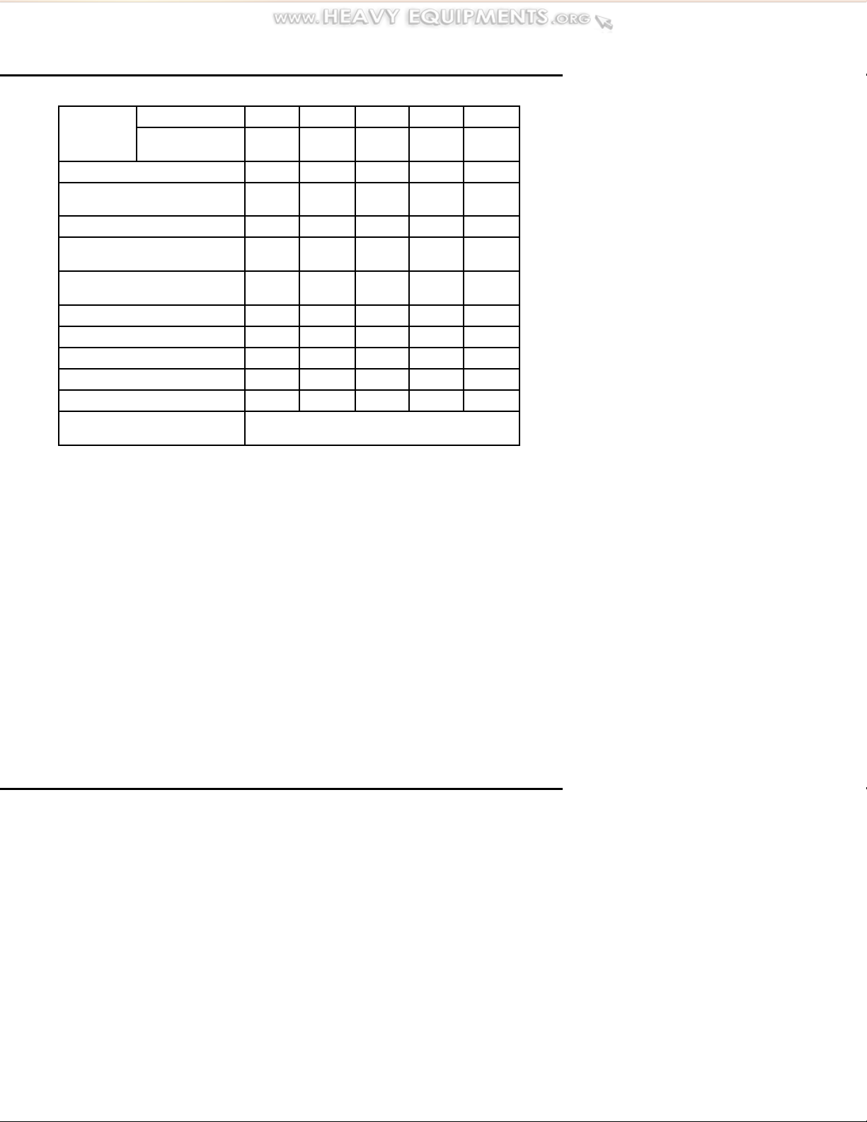
SERIES 50 OPERATOR'S GUIDE
Hours 300 600 900 1,200 1,500
Item
17. Engine (Steam Clean)
18. Radiato r & A/A Charge
Cooler
19. Oil Pressure I I
20. Battery Charging
Alternator*
21. Engine & Transmission
Mounts
22. Crankcase Pressure I I
23. Fan Hub I
24. Thermostats & Seals
25. Crankcase Breather I
26. Engine Tune-Up I
27. Vibration Damper
All items are described in PREVENTIVE MAINTENANCE INTERVALS.
I – Inspect, service, correct or replace as necessary.
R –Replace.
Miles/Km
(X 1000)
6/1.6 12/9.6 18/28.8 24/38.4 30/48
I I I I I
I I I I I
I I
Replace at major engine overhaul or
earlier if dented or leaking.
Table 12 Fire Fighting, Crash/Rescue and Emergency Vehicle
Engine Regular Maintenance Intervals (continued)
All information subject to change without not ice. (Rev. 01/ 04) 59
6SE550 0401 Copyright © 2004 DETROIT DIE
SEL CORPORATION

MAINTENANCE
Item
1. Lubricating Oil I I*
2. ]Fuel Tank I I
3. Fuel Lines & Flexible Hoses I
4. Cooling System I I*
5. Turbocharger I
6. Battery I
8. Drive Belts I I
10. Air System, Cleaner I I
12. Fuel Filters, Water Separator I I*
16. Exhaust System I
19. Oil Pressure I I*
Load Test P
All items are described in PREVENTIVE MAINTENANCE INTERVALS.
I – Inspect, service, correct or replace as necessary.
P –Perform
* Perform these items at time of load test. Load test should be at
least 35% of the uni t's full rated output. Refer to generator set
manufacturer's instructions.
Prime
Daily
Standby
Monthly
Table 13 Generator Set Engine Prime Daily and Standby Monthly
Maintenance Intervals
60 All information subject to change without notice. (Rev. 01/ 04)
6SE550 0401 Copyright © 2004 DETROIT DIE
SEL CORPORATION

SERIES 50 OPERATOR'S GUIDE
Item
150 300 600 1,000 1,500 2,000 3,000 4,000
Hours
Standby: Replace every 150 hours or 1 year,
1. Lubricating Oil
rime: Replace every 250 hours or 3 months,
P
whichever comes first.
whichever comes first.
2. Fuel Tank I
3. Fuel Lines &
Flexible Hoses
I R
4. Cooling System R
6. Battery I
7. Tachometer
Drive
I
8. Drive Belts I
10. Air Cleaner I
11.
Lube Oil Filters
Replace when lubricating oil is changed.
Standby: Replace every 150 hours or 1 year,
12. Fuel Filters
rime: Replace every 150 hours or 3 months,
P
whichever comes first.
whichever comes first.
13. Coolant Pump/
Inhibitor Level
14.
Cranking Motor
Follow manufacturer's recommendations.
I
All items are described in PREVENTIVE MAINTENANCE INTERVALS.
I – Inspect, service, correct or replace as necessary.
R – Replace
Table 14 Generator Set Engine Regular Maintenance Intervals
All information subject to change without not ice. (Rev. 01/ 04) 61
6SE550 0401 Copyright © 2004 DETROIT DIE
SEL CORPORATION

MAINTENANCE
Item
16. Exhaust System I
17. Engine
(Steam Clean)
18. Radiator I
19. Oil Pressure I
20. Battery
Charging
Alternator
21. Engine &
Generator
Mounts
22. Crankcase
Pressure
23. Fan Hub I
24. Thermostats &
Seals
25. Crankcase
Breather
26. Engi ne Tune-Up I
27. Vibration
Damper
All items are described in PREVENTIVE MAINTENANCE INTERVALS.
I – Inspect, service, correct or replace as necessary.
R – Replace
150 300 600 1,000 1,500 2,000 3,000 4,000
I
I
I
Replace at major engine overhaul or earlier
Hours
I I
I R
if dented or leaking.
R
Table 15 Generator Set Engine Regular Maintenance Intervals
(continued)
62 All information subject to change without notice. (Rev. 01/ 04)
6SE550 0401 Copyright © 2004 DETROIT DIE
SEL CORPORATION

SERIES 50 OPERATOR'S GUIDE
PREVENTIVE
MAINTENANCE
INTERVALS
The following is intended as a
guide for establishing preventive
maintenance intervals. The
recommendations given should
be followed as closely as possible
to obtain long life and optimum
performance from y our engine.
Maintenance intervals indicated are
time (hours) of actual operation.
The intervals shown apply only to
the maintenance functions described
and should be coordinated with other
regularly scheduled maintenance.
The “Daily” instructions apply to
routine or daily starting of the en g ine.
They do not apply to a new engine
or one that has been operated for a
considerable period of time.
For new or stored engines, refer
to Section 13.1, “Prep arations for
Starting the Engine the First Time,” in
the Series 50 Service Manual (6SE50).
Item 1 – Lubric ating Oil
Check the oil lev e l daily with the
engine stopped. If the engine has
just been stopped and is warm, wait
approximately 20 m inutes to allow the
oil to drain back into the oil pan before
checking. Add the proper grade of oil
to mainta in the correct level on the
dipstick. See Figure 10.
Figure 10 Check Oil Level Daily
NOTICE:
When adding lubricating oil, do
not overfill. Oil may be blown out
through the crankcase breather if
the crankcase is overfilled.
Preventive maintenance other than the
“Daily” checks should be performed
by authorized Detroit Diesel service
outlets. These outlets have the trained
personnel and special tools to properly
perform all services.
All information subject to change without not ice. (Rev. 01/ 04) 63
6SE550 0401 Copyright © 2004 DETROIT DIE
SEL CORPORATION

MAINTENANCE
Figure 11 Engine Oil Consumption Guidelines
All diesel engines are designed to
use some oil, so the periodic addition
of oil is normal. See Figure 11 to
determine the degree of oil usage.
NOTICE:
If the oil level is constantly above
normal and excess oil has not been
added to the crankcase, consult with
an authorized Detroit Diesel service
outlet. Fuel or coolant dilution of
lubricating oil can result in s erious
engine damage.
Before adding lubricating oil,
refer to How to Select Lubricating
Oil in this guide. Change lubricating
oil and filters a t the intervals
listed in Table 16 when using fuel
with a sulfur conten t of less than 0.05
mass percent. When using fuel with a
higher sulfur content, refer to When to
Change Oil in this guide.
64 All information subject to change without notice. (Rev. 01/ 04)
6SE550 0401 Copyright © 2004 DETROIT DIE
SEL CORPORATION

SERIES 50 OPERATOR'S GUIDE
Service Application Lube Oil and Filter Change Interval*
Highway Truck & Motor Coach 15,000 Miles (24,000 Kilometers)
City Transit Coach except model
6047MK1E
City Transit Coach Model 6047MK1E 3,000 Miles (4,800 Kilometers)
Fire Fighting, Crash/Rescue, &
Emergency Vehicles
Construction, Industrial & Agricul tural 250 Hours or 1 Year, whichever comes
Stationary Generator – Prime Power
or Continuous
Stationary Generator – Standby 150 Hours or 1 Year, whichever comes
* Change both full-flow filter s when lube oil is changed.
6,000 Miles (9,600 Kilometers), 300
Hours or 3 Months, whichever comes
first
6,000 Miles (9,600 Kilometers), 300
Hours or 1 Year, whichever comes first
first
300 Hours or 3 Months, whichever
comes first
first
Table 16 Recommended Engine Oil Drain and Filter Change
Intervals (Diesel Fuel Sulfur Content Less Than 0.05 Mass
%)
Item 2 – Fuel and Fuel Tank
Keep the fuel tank filled to reduce
condensation. See Figure 12.
Before adding fuel, refer to section
How to Select Fuel Oil in the How To
section of this guide.
Refill the tank at the end of each day's
operation to prevent conden sation
from contaminating the fuel.
Condensation formed in a partially
filled tank promotes the growth of
microorganisms that can clog fuel
filters and restrict fuel flow.
To prevent microbe growth, add a
biocide to the fuel tank or primary
fuel supply.
Figure 12 Filled Fuel Tank
All information subject to change without not ice. (Rev. 01/ 04) 65
6SE550 0401 Copyright © 2004 DETROIT DIE
SEL CORPORATION

MAINTENANCE
Water accumulation can be controlled
by using additives containing methyl
carbitol or butyl cel lusolve. Follow
manufacturer's usage, handling and
safety precautions.
Open the drain at the bottom of
the fuel tank every 30,000 miles
(48,000 kilometers) or 300 hours for
construction/industrial applications to
drain off any water and/or sediment.
To avoid injury from improper use
of chemicals, follow the chemical
manufacturer’s usage, handling,
and disposal instructions.
Observe all manufacturer’s
cautions.
Every 120,000 miles (192,000
kilometers), 12 months, or 600
hours for construction/industrial
applications tighten all fuel tank
mountings and brackets. At the same
time, check the seal in the fuel tank
cap, the breather hole in the cap and
the condition of the flexible fuel
lines. Repair or replace the parts, as
necessary.
NOTICE:
Galvanized steel fuel tanks, fittings,
pipes or supply lines should never
be used, because the fuel reacts
chemically with the zinc coating to
form powdery flakes that can quickly
clog the fuel filters and damage the
fuel pump and injectors.
Item 3 – Fuel Lines, Flexible
Hoses
A pre-start inspectio n for leaks and of
hosese and fittings must be made.
Leaks — Makeavisualcheckfor
fuel leaks at all engine-mounted fuel
lines and connections, and at the
fuel tank suction and return lines.
Since fuel tanks are susceptible to
road hazards, leaks in this area may
best be detected by checking for an
accumulation of fuel under the tank.
To avoid inj ury from fire, contain
and eliminate leaks of flammable
fluids as they occur. Failure to
eliminate leaks could result in
fire.
66 All information subject to change without notice. (Rev. 01/ 04)
6SE550 0401 Copyright © 2004 DETROIT DIE
SEL CORPORATION
SERIES 50 OPERATOR'S GUIDE
Leaks are no t only detrimental to
machine operation, but they can also
result in added expen se caused by the
need to replace lost fluids.
Hoses and Fittings — Check
hoses daily as part of the pre-start
inspection. Examine hoses for leaks,
and check all fittings, clamps and
ties carefully. Make sure hoses are
not resting on or touching shafts,
couplings, heated surfaces including
exhaust manifolds, any sharp edges,
or other obviously hazardous areas.
Since all machinery vibrates and
moves to a certain extent, clamps and
ties can fatigue with age. To ensure
continued proper support, inspect
fasteners frequently and tighten or
replace them as necessary. If fittings
have loosened or cracked or if hoses
have ruptured or worn through, take
corrective action immediately.
Hose Service Life — A hose has
a finite service life. With this in
mind, all hoses should be thoroughly
inspected at least every 500 operating
hours (1,000 hours for fire-resistant
fuel and lubricating oil hoses) and/or
annually. Look for cover damage
and/or indications of twisted, worn,
crimped, brittle, cracked or leaking
lines. Hoses with their outer cover
worn through or with dam a ged metal
reinforcements should be considered
unfit for fu rther service.
All hoses in and out of machinery
should be replaced during major
overhaul and/or after a maximum of
five (5) years of service.
NOTE:
Fire-resistant fuel and lube oil hose
assemblies do not require automatic
replacement after five years of service
or at major overhaul, but should be
inspected carefully before being put
back into service.
Item 4 – Cooling System
The cooling system must be full for
proper operation of the engine.
To avoid injury from the expulsion
of hot coolant, never remove the
cooling system pressure cap
whiletheengineisatoperating
temperature. Remove the cap
slowly to reliev e pressure. Wear
adequate protective clothing
(face shield or safety goggles,
rubber gloves, apron, and boots).
Coolant Level — Check the coolant
level daily and m aintain it near the
bottom of the filler neck on the
radiator. On so me installations this
is done by checking an overflow
bottle or sight glass. Add coolant as
All information subject to change without not ice. (Rev. 01/ 04) 67
6SE550 0401 Copyright © 2004 DETROIT DIE
SEL CORPORATION

MAINTENANCE
required, but do not overfill. Before
adding coolant, refer to section How
to Select Coolant in this guide.
Make a daily visual check for
cooling system leaks. Look for an
accumulation of coolant when the
engine is running and when it is
stopped. Coolant leaks may be more
apparent on a engine when it is cold.
Coolant Inhibito rs — The
inhibitors in antifreeze solutions must
be replenished with a non-chromate
corrosion inhibitor supplement when
indicated by testing the coolant.
Refer to section How to Select
Coolant for required test intervals and
inhibitor levels.
NOTICE:
Failure to check and maintain
SCA (supplemental coolant
additive) levels at required
concentrations will result in
severe damage (corrosion) to
the engine cooling system and
related components.Coolant
must be inhibited with the
recommended SCA's listed in
this guide. In addition, the engine
can be equipped with a coolant
filter/inhibitor system as an installed
option or as an after-sale item.
Coolant Drain Interval —
Detroit Diesel recommends
replacing coolant at the intervals
listed in Table 1 7.
A coolant system properly maintained
and protected with supplemental
coolant inhibitors can be operated
up to the intervals listed. At
these intervals the coolant must
be drained and disposed of in an
environmentally responsible manner
according to state and/or federal
(EPA) recommendations.
68 All information subject to change without notice. (Rev. 01/ 04)
6SE550 0401 Copyright © 2004 DETROIT DIE
SEL CORPORATION

SERIES 50 OPERATOR'S GUIDE
Coolant Type Coolant Replacement Interval
A 50/50 mix of PowerCool®fully
formulated, inhibited ethylene glycol
antifreeze and water or a 50/50 mix of
fully formulated, inhibited propylene
glycol antifreeze and water
A 50/50 mix of phosphate-free TMC
RP-329 “Type A“ (propylene glycol)
antifreeze and water.
A 50/50 mix of OAT (organic acid
technology) coolant and water.
1
Proper maintenance involves periodic evaluation using PowerTrac
3-Way Coolant Test Strips and the addition of required SCA, as
indicated by the test strip.
2
To verify coolant acceptability, submit a sample to DD C for coolant
analysis every 3 years, 300,000 miles (480,000 km) or 6,000
operating hours, whichever comes first. Submit sample using
PowerTrac coolant analysis kit, part number 23516921 (IEG/IPG
coolant) or 23523398 (organic coolant).
3
OAT coolants require the addition of an extender every 2 years,
300,000 miles (480,000 km), or 5,000 hours, whichever comes first.
Use 1 pint to 20 gallons of OAT coolant.
With proper mainten an ce1coolant
can be operated 2 years, 300,000
miles (480,000 km), or 4,000 hours,
whichever comes first. At this time the
cooling system must be completely
drained and cleaned before refill.
With proper maintenance1coolant can
be operated for the life of the engine
until overhaul.
2
Forlifetooverhaul,
pre-charged c oolant in combination
with a need-release filter must be
used. At this time the cooling system
must be completely drained and
cleaned before refill.
With proper mainte nance coolant can
be operated 4 years, 600,000 miles
(960,000 k m), or 10,000 operating
hours, whichever comes first.
this time the cooling system must
be completely drained and cleaned
before refill.
3
At
®
Table 17 Coolant Drain Intervals
All information subject to change without not ice. (Rev. 01/ 04) 69
6SE550 0401 Copyright © 2004 DETROIT DIE
SEL CORPORATION

MAINTENANCE
Item 5 – Turbocharger, Air-to-Air
Charge Cooler
Visually inspect the turbocharger
mountings, intake and exhaust ductin g
and connections for leaks daily. Check
the lube oil inlet and outlet lines fo r
leaks or restrictions to oil f low. Check
for unusual noise or vibration and, if
excessive, stop the engine and do not
operate until the cause is determined.
To avoid injury from hot surfaces,
allow engine to cool before
removing any component. Wear
protective gloves.
Periodically inspect the air-to-air
charge cooler (if used) for buildup of
dirt,mud,etc. andwashoff. Check
the charge cooler, ductwork, and
flexible connections for leaks and
have repaired or replaced, as required.
Wastegated Turbochargers —
The turbocharger wastegate actuator
is factory-calibrated and is not
adjustable. Check actuator operation
at the intervals shown in the
maintenance schedule.
To avoid injury from flying debris
when using compressed air, wear
adequate eye protection (face
shield or safety goggles) and do
not exceed 40 psi (276 kPa) air
pressure.
NOTICE:
Do not exceed 30 psi (207 kPa) air
pressure when checking wastegate
actuator operation. Excessive air
pressure can damage the actuato r.
Check turbocharger heat-insulating
exhaust system blankets (if used) for
damage on a daily basis. Torn, matted,
crushed, oil-soaked or otherwise
To verify correct wastegate actuator
operation, apply 30 psi (20 7 kPa)
of regulated shop air and watch for
actuator rod movement.
damaged insulation blankets must be
replaced immediately.
70 All information subject to change without notice. (Rev. 01/ 04)
6SE550 0401 Copyright © 2004 DETROIT DIE
SEL CORPORATION

SERIES 50 OPERATOR'S GUIDE
Item6–Battery
Check the hydrometer “eye” of
maintenance-free batteries for charge.
See Figure 13.
Figure 13 Check “Eye” of
Maintenance-Free
Batteries
To avoid injury from accidental
engine startup while servicing
the engine, disconnect/disable
the starting system.
Maintain the electrolyte level
according to the battery manufacturer's
recommendations, but do not overfill.
Overfilling can cause poor battery
performance or early failure.
Keep the terminal side of the b a tter y
clean. When necessary, wash with
a solution of baking soda and water.
Rinse with fresh water. Do not allow
the soda solution to enter the cells.
Inspect the cables, clamps and
hold-down brackets regularly. Clean
andreapplyalightcoatingof
petroleum jelly when needed. Have
corroded or damaged parts replaced.
If the engine is to be out of service
formorethan30days,removethe
batteries and store in a cool, dry
place. Keep batteries fully charged,
if possible. Replace any battery that
fails to hold a charge.
Periodically check battery connections
for corrosion an d tightness. If
necessary, remove connections
and wire brush any corrosion from
terminals and cable ends. Replace
damaged wiring.
If lead-acid or low-maintenance
batteries are used, check the specific
gravity of each cell every 150
operating hours. Check more
frequently in warm weather due to
the more rapid loss of water through
evaporation.
All information subject to change without not ice. (Rev. 01/ 04) 71
6SE550 0401 Copyright © 2004 DETROIT DIE
SEL CORPORATION

MAINTENANCE
Item 7 – Tachometer Drive
A typical tachometer drive take-off
location is the camshaft drive gear
result in crankshaft breakage. A loose
belt will slip and may cause damage
to accessory components.
access cover on the front of the gear
case cover. Lubricate t he tachometer
drive (if so equipped) every 150 hours
or 15,000 miles (24,000 km) with an
all-purpose grease. At temperatures
above – 1
C(+30 F) use a No. 2
grade g rease. Use a N o. 1 grade
To avoid injury from rotating belts
and fans, do not remove and
discard safety guards.
grease below this temperature.
Item 8 – Drive Belts
Belts should be n either too tight nor
too loose. Belts that are too tight
impose extra loads on the crankshaft,
fan and/or alternator bear ings,
shortening both belt and bearing life.
Use a belt tension gage, such
as Kent-Moore
®
(V-belt), J 23600–B (poly-V belt),
J 41251 (Po w erBand
poly-V belt), or equivalent, when
tensioning drive belts. Tension belts
to the values listed in Table 18.
Excessively overtightened belts can
Fan Drive
Single Belt
80–100lbs(356–445N) 60–80lbs(267–356N)
Alternator Drive
Belt New Used
Two 1/2–in. V-Groove
2–Groove PowerBand
12–Rib Poly-V (50 DN Alternator)
®
125 lbs (556 N) 100 lbs (445 N)
200 lbs (890 N) 150 lbs (667 N)
350 lbs (1,557 N) 250 lbs (1,112 N)
2or3Belts
tool J 23586–B
®
and 12–rib
Table 18 Drive Belt Tensioning
72 All information subject to change without notice. (Rev. 01/ 04)
6SE550 0401 Copyright © 2004 DETROIT DIE
SEL CORPORATION

SERIES 50 OPERATOR'S GUIDE
V-Belts — New standard V-belts
will stretch after the first few hours
of operation. Tighten V-belts as
listed in Table 18. Run the engine
for 10 to 15 minutes to seat the belts,
then readjust tension. Check and
retension belts after 1/2 hour and
again after 8 hours or 250 miles (400
km) of operation. Thereafter, check
the tension of the drive belts every
100 hours or 6,000 miles (10,000 km)
and adjust, if necessary.
If a belt tension gage is not available,
adjust the belt tension so that a firm
push with the thumb, at a point
midway between the two pulleys, will
depress the belt .50 in. – .75 in. (13
– 19 mm).
2-Groove PowerBand — The
2-groove PowerBand
®
is used with
the 50 DN alternator. To provide
proper running tension for the belt,
current Series 50 engines use an auto
belt tensioner, which requires no
adjustment. See Figure 14.
tensioning, measure belt tension
every month or every 7,500 miles
(12,000 km), whichever comes first.
Retension belt to 150 lbs (667 N) at
these intervals.
Figure 14 Auto Belt Tensioner
Assembly with 50 DN
Alternator
Earlier-built Seri e s 50 engines have
a m anual belt tensioner assembly.
See Figure 15.
Tighten a new PowerBand
®
drive belt
Figure 15 Manual Tensioner
Assembly with 50 DN
Alternator
to 200 lbs (890 N), then run the engine
for 10 minutes at 1200 rpm. Stop the
engineandallowa10–15minute
cool down period. Check tension. If
less than 150 lbs (667 N), retension
to 150 lbs (667 N). Following initial
All information subject to change without not ice. (Rev. 01/ 04) 73
6SE550 0401 Copyright © 2004 DETROIT DIE
SEL CORPORATION

MAINTENANCE
12–Rib Poly-V Belt — Tighten a
12–rib poly-V belt to 350 lbs (1,557
N), then run the engine at high idle for
30 minutes. Stop the en gine and allow
a 10 – 15 m inute cool down period.
Check tension with tool J 41251–B
or equivalent. If tension is 250 lbs
(1,112 N) or more, no retensioning is
required. If tension is less than 250 lbs
(1,112 N), retension to 250 lbs (1,112
N). Measure belt tension every month
or every 7,500 miles (12,000 k m),
whichever comes first. Retension to
250 lbs (1,112 N) as required.
Belt Replacement — Drive belts
(V and poly-V) should be replaced
every 2,000 hours or 100,000 miles
(160,000 km).
Replace all belts in a set when one
is worn. Single belts of similar size
should not be used as a substitute for
a matched belt set. Premature b elt
wear can result because of belt length
variation. All belts within a matched
set are within .032 in. (0.8 mm) of
their specified center distances.
When installing or adjusting an
accessory drive belt, be sure the bolt
at the accessory adjusting pivot point
is properly tightened, as well as the
bolt in the adjusting slot. In addition,
check the torque on the alternator an d
bracket mounting bolts. Retighten as
required.
Item 9 – Air Compressor
All air compressor intake parts
should be removed and cleaned at the
following intervals:
On Highway Vehicle Engines –
7,500 miles (12,000 km)
Industrial Engines – 150 Hours or
4,500 miles (7,200 km)
To clean either the hair type or the
polyurethane type compressor air
strainer element, saturate it and
squeeze it in fuel oil or any other
cleaning agent that is not detrimental
to the element until it is dirt-free. Then
saturate the elem e nt in lubricating oil
and squeeze it dry before placing it
back into the air strainer.
For air strainer replacement,
contact the nearest servicing dealer.
Replace hair type elements with the
polyurethane type, if available.
The air compressor mounting bolts
should be tightened every 12 months
or 30,000 miles (48,000 km) for
on-highway engines or every 300
hours for industrial applications.
74 All information subject to change without notice. (Rev. 01/ 04)
6SE550 0401 Copyright © 2004 DETROIT DIE
SEL CORPORATION

SERIES 50 OPERATOR'S GUIDE
Item 10 – Air Cleaner
The air cleaner element should be
inspected every 15,000 miles (24,000
km) for vehicle engines, 150 hou rs for
non-vehicle engines, or more often if
the engine is operated under severe
dust conditions. Replace the element,
if necessary. Check the gaskets for
deterioration and replace, if necessary.
If the dry type air cleaner is equipped
with an aspirator, check for aspirator
damage or clogging. Clean, repair or
replace, as necessary.
Dry type air cleaner elements
should be replaced after one year
of service or when the maximum
allowable air in take restriction has
been reached, whichever comes first.
Refer to section When to Service the
Dry Type Air Cleaner in this guide for
additional information.
NOTICE:
piping or boots an d loose or damaged
clamps. Have worn or damaged parts
repaired or replaced, as required.
Retighten loose connections.
Item 11 – Lubricating Oil Filters
For on-highway vehicle engines,
install new spin-on oil filters at a
maximum of 15,000 miles (24,000
km). For city transit coach engines,
install filters at a maximum of 6,000
miles (9,600 km). For industrial
engines, install filters every 150 hours
of operation or each time the engine
oil is changed, whichever comes first.
To avoid injury from slipping and
falling, immediately clean up any
spilled liquids.
Do not allow the air inlet restriction
to exceed 20 inches of water (5.0
kPa) under any engine operating
conditions. A clogged air cleaner
element will cause excessive
intake restriction and a reduced
air supply to the engine. This, in
turn, can result in increased fuel
consumption, inefficient engine
operation and reduced e ngine life.
Install the new f ilters, turning them
until they contact the gasket fully w ith
no side movement. Turn full-flow
filters an additio nal 2/3 turn by
hand, or as indicated on the filter.
See Figure 16.
Inspect the entire air system for leaks
daily. Look especially for torn air inlet
All information subject to change without not ice. (Rev. 01/ 04) 75
6SE550 0401 Copyright © 2004 DETROIT DIE
SEL CORPORATION

MAINTENANCE
Figure 16 Lubricating Oil Filters
Make a visual check of all lubricating
oil lines for wear and/or chafing. If
any indication of wear is evident,
replace the oil lines and correct the
cause.
Check for oil leaks after starting the
engine.
At normal operating speed and with
the standard .080 inch restriction
fittings, the fuel pressu re is 55 – 70
psi (375 – 483 kPa). Change the fuel
filters whenever the inlet restrictio n
at the pump reaches 12 inches of
mercury (41 kPa) at normal operating
speeds and whenever the fuel pressure
at the inlet fitting falls to the minimum
fuel pressure of 6 inches of mercury
(20.3 kPa).
NOTE:
Filter change intervals may be
shortened to conform with established
preventive maintenance schedules,
but should never be extended.
Fuel Pro®382 Filters — Install
new Fuel Pro
®
382 primary fuel filter
elements when the fuel level in the
see-thru cover reaches the top of the
element or after one year of service,
whichever comes first.
Item 12 – Fuel Filters
One method o f determining when
filters are plugged to the extent that
they need replacing is based on the
fuel pressure at the cylinder head fuel
inlet fitting and the inlet restriction
Spin-On Filters — Install new
spin-on primary and secondary fuel
filter elements on vehicle engines
every 15,000 miles (24,000 km) or
every six months, whichever comes
first. See Figure 17.
at the fuel pump. In a clean system
the maximum pump inlet restriction
should not exceed 6 inches of mercury
(20.3 kPa). In a dirty system it must
not exceed 12 inches of mercury (41
kPa).
76 All information subject to change without notice. (Rev. 01/ 04)
6SE550 0401 Copyright © 2004 DETROIT DIE
SEL CORPORATION

Figure 17 Spin-On Fuel Filter
Location
Install new spin-on filter elements
on non-vehicle engines every 150
hours. Replace spin-on filter elements
immediately if plugging is indicated,
regardless of mileage or hour intervals.
Item 13 – Water Pump and
Coolant Inhibitor Element
SERIES 50 OPERATOR'S GUIDE
Coolant Inhibitor Element — If
the cooling system is protected by a
supplemental coolant additive (SCA)
element, the coolant must be tested
at required intervals and the element
replaced, if required. See Figure 18.
Check the water pump and the coolant
inhibitor element.
Water Pump Drain Hole — The
Figure 18 Coolant Inhibitor
Element
water pump drain hole should be
inspected every 6 months to make
sure it is open. A small chemical
build-up or streaking at the drain hole
may occur. This is not an indication
of a defective water pump or seal.
Remove the build-up with a mild
detergent cleaner and a brush. If
Required test intervals are
listed in Table 25. For SCA test
procedures refer to How to Select
Coolant and then SCA Test Procedures
in this guide. Use the coolant filter
element required.
coolant does not leak from the drain
hole under normal conditions, d o not
replace the water pump.
All information subject to change without not ice. (Rev. 01/ 04) 77
6SE550 0401 Copyright © 2004 DETROIT DIE
SEL CORPORATION

MAINTENANCE
Refer to SPECIFICATIONS for
element part number listing. The
valves mounted on the filter adaptor
head must be opened after the element
is replaced.
Item 14 – Cranking Motor
For cranking motor (starter)
information, contact an authorized
Delco Remy
®
or Bosch®service
center, depending on m anufacturer.
Item 15 – Air System
All the connections in the air system
should be checked to make sure
they are tight and leak free. Check
all hoses and ducting for punctures,
deterioration or other d a mag e and
replace, if necessary.
Item 16 – Exhaust System
Have the exhaust manifold retaining
bolts and other connections checked
for tightness. Have the exhaust pipe
rain cap checked for proper operation,
if so equipped.
NOTICE:
Do not apply steam or solvent
directly to the battery-charging
alternator, starting motor, DD E C
components, sensors or other
electrical components, as damage
to electrical equipment may result.
Item 18 – Radiator
The exterior of the radiator core
should be inspected every 30,000
miles (48,000 km), 12 months, or 300
hours ( industrial ap plications) and
cleaned, if n ecessary.
To avoid injury from flying debris
when using compressed air, wear
adequate eye protection (face
shield or safety goggles) and do
not exceed 40 psi (276 kPa) air
pressure.
Item 17 – Engine (Steam Clean)
Steam clean the engine and engine
compartment every 60,000 miles
(96,000 km ) or 2,000 hours,
whichever comes first.
as mineral spirits, and dry with
compressed air. Fuel oil, kerosene or
gasoline should not be used.
It may be necessary to clean the
radiator more frequently if the engine
is being operated in extremely dusty
or dirty areas.
Use a quality grease solvent, such
78 All information subject to change without notice. (Rev. 01/ 04)
6SE550 0401 Copyright © 2004 DETROIT DIE
SEL CORPORATION

SERIES 50 OPERATOR'S GUIDE
If the low coolant level sensor is
installedinthetoptankoftheradiator,
it should be tested for proper operation
every 100 ,000 miles (160,000 km)
or 12 months, whichever comes first.
Authorized Detroit Diesel distributors
are properly equipped to perform this
service.
Item 19 – Oil Pressure
Under normal o peration , oil pressure
is noted each time the engine is
started. In the event the equipment
has warn ing lights rather than pressure
indicators, the pressure should be
checked and recorded every 60,000
miles (96,000 km) for vehicle engines
or 600 hours for stationary and
industrial engines.
Item 20 – B attery-Charging
Alternator
Precautions must be taken when
working on or aroun d the alternator.
The diodes and transistors in the
alternator circuit are very sensitive
and can be easily destroyed.
2. Do not reverse battery
connections. This can also
cause damage.
3. Never disconnect the battery
while the alternator is operating.
Disconnecting the batter y can
result in damage to the battery
diodes. In applications which
have two (2) sets of batteries,
switching from one set to the
other while the engine is running
will momentarily disconnect
the batteries. This can result in
equipment damage.
4. If a booster battery is to be used,
batteries must be connected
correctly (negative to negative,
positive to positive) to avoid
equipment damage.
5. Never use a fast charger with the
batteries connected or as a booster
for battery output.
For information on the alternator
assembly, contact an authorized
Delco Remy
®
or Bosch®distributor,
depending on manu facturer.
1. Avoid grounding the output
terminal. Grounding an
alternator's output wire or
terminal (which is always “hot,”
regardless of whether or not
the engine is running) and
accidentally reversing the battery
polarity will result in equipment
damage.
All information subject to change without not ice. (Rev. 01/ 04) 79
6SE550 0401 Copyright © 2004 DETROIT DIE
SEL CORPORATION

MAINTENANCE
To avoid injury from battery
explosion or contact with battery
acid, work in a well-ventilated
area, wear protective clothing,
and avoid sparks or flames
near the battery. Always
establish correct polarity before
connecting cables to the battery
or battery circuit. If you come in
contact with battery acid:
Flush your skin with water.
Applybakingsodaorlimeto
help neutralize the acid.
Flush your eyes with water.
Get m edical attention
immediately.
Bosch®T1 Alternator Service
Requirements — The transistor
regulator must b e replaced every
100,000 m iles (160,000 km) using
kit part number 235246 13 (includes
regulator assembly and brushes).
Front and rear bearings must be
replaced every 200,000 miles
(320,000 km) using k it 23524614
(includes bearings, seals and spacer
ring). Authorized Bosch distributors
have the parts, tools and trained
personnel to perform these services.
General Service Requirements
–Bosch
®
and Delco Remy
®
Alternators — Terminals should
be checked for corrosion and loose
connections and wiring inspected
for damage and frayed insulation.
Have wiring repaired or replaced, as
required.
Check torque on alternator mounting
bolts and brack eting every 15,000
miles (24,000 km) on truck and coach
engines or every 300 hours on all
other engines. Retighten, if necessary.
Item 21 – Engine and
Transmission Mounts
The engine and transmission mounting
bolts and the condition of the m o unting
pads should be checked every 60,000
miles (96,000 km) or 600 hours.
Tighten and/or rep a ir as necessary.
Item 22 – Crankcase Pressure
The crankcase pressure should be
checked and recorded every 60,000
miles (96,000 k m ) or 600 ho urs.
80 All information subject to change without notice. (Rev. 01/ 04)
6SE550 0401 Copyright © 2004 DETROIT DIE
SEL CORPORATION

Item 23 – Fan Hub
If the fan bearing hub assembly has a
grease fitting, use a hand grease gun
to lubricate the bearings with one shot
of quality lithium-base, multi-purpose
grease every 1 00,00 0 miles (160,000
km) for vehicle engines or 1,000 hours
for non-vehicle engines. Care should
be taken not to overfill the beari ng
housing.
Item 24 – Thermostats and Seals
Replace the therm ostats and seals
every 240 ,000 miles (384,000 km)
on vehicle engines. On non-vehicle
engines, replace the thermostats and
seals every 4,000 hours or 24 months,
whichever comes first.
Item 25 – Crankcase Breather
SERIES 50 OPERATOR'S GUIDE
Figure 19 Internal (in Rocker
Cover) Breath er
Location
The rocker cover-mounted breather
assembly (part number 23512984)
used in the closed crankcase breather
system should be replaced every 4000
operating hours. It is not reusable and
no attempt should be made to clean or
reuse it. See Figure 20.
The internally mounted (in the engine
rocker cover) crankcase breather
assembly should be removed and
the steel mesh pa d washed in clean
fuel oil every 100,000 to 120,000
miles (160,000 to 192,000 km) on
vehicle engines or every 1,000 hours
of operation on non-vehicle engines.
This cleaning period m ay be reduced
or lengthened according to the severity
ofservice. SeeFigure19).
All information subject to change without not ice. (Rev. 01/ 04) 81
6SE550 0401 Copyright © 2004 DETROIT DIE
Figure 20 Rocker Cover-Mounted
Breather
SEL CORPORATION

MAINTENANCE
Item 26 – Engine Tune-Up
There is no scheduled interval for
performing an engine tune-up.
However, the valve lash and injector
heights must be measured and, if
necessary, adjusted at the initial
interval listed in Table 19. Once the
initial measurements/adjustments
have been made, any adjustments
beyond th is point should be made only
as required to maintain satisfactory
engine performance.
Item 27 – Vibration Damper
The viscous vibration damper should
be inspected periodically and replaced
if dented or leaking. See Figure 21.
Heat from normal engine operation
may, over a period of time, cause the
fluid within the damper to break down
and lose its dampening properties.
For this reason the viscous vibration
damper must be replaced at time
of normal major engine overhaul,
regardless of apparent condition.
Figure 21 Viscous Vibration
Damper
Engine Application
Vehicle Engines
Stationary, Construction/Industrial,
Agricultural, or Generator Set Engines
* Whichever comes first.
Initial Valve Lash and Injector Height
Measurement/Adjustment Period
60,000 Miles (96,000 km) or
24 Months*
1,500 Hours or 45,000 Miles
(72,000 km)*
Table 19 Valve Lash and Injector Height Adjustment
82 All information subject to change without notice. (Rev. 01/ 04)
6SE550 0401 Copyright © 2004 DETROIT DIE
SEL CORPORATION

HOW-TO SECTION
This section covers Detroit Diesel's
recommendations o n how to select
lubricating oil, fuel oil, and coolant
and includes basic engine maintenance
procedures which can be performed
by the operator.
NOTICE:
The manufacturer's warranty
applicable to Series 50 engines
provides in part that the provisions
of such warranty shall not apply
to any engine unit that has been
subject to misuse, negligence or
accident. Accordingly, malfunctions
attributable to neglect or failure to
follow the manufacturer's fuel or
lubricating recommendations may
not be within the coverage of the
warranty.
How to Select Lubricating
Oil
The selection of the proper lubricating
oil is important to achieve the long
and trouble-free service which Detroit
Diesel engines are designed to
provide. The proper lubricating oil for
all Detroit Diesel engines is selected
basedonSAEviscositygradeand
API (American Petroleum Institute)
service designation. Only oils licensed
to display the API symbol should be
used. See Figure 22.
SERIES 50 OPERATOR'S GUIDE
Figure 22 API Symbol
Lubricant Requirements
Lubricant requirements are different
for the EGR-equipped and non-EGR
engines.
EGR-Equipped Engines — API
CI-4 oils must be used in October
2002 and later–build Series 50
engines with cooled EGR (exhaust
gas recirculation) devices. API
Service Category CI-4 is intended for
use with cooled EGR engines m eeting
2002 and later exhaust emission
regulations.
Non-EGR Engines — API CI-4 or
CH-4 oils are recommended for use i n
all non-EGR engines.
Engines Built Prior to 1998 —
Lubricants meeting API Service
All information subject to change without not ice. (Rev. 01/ 04) 83
6SE550 0401 Copyright © 2004 DETROIT DIE
SEL CORPORATION

HOW-TO SECTION
CategoryCG-4maybeusedin
engines built prior to 1998 when API
CI-4 or CH-4 oils are not available.
NOTE:
The use of CG-4 oils in these
engines may require a reduction in
oil drain interval, depending upon the
application and the fuel sulfur level.
Cold Weather Starting
At ambient temperatures below –20
C(–4 F) when sufficient starter
speed cannot be achieved with SAE
15W-40 oils, the use of 5W-XX oils
and 10W-XX oils, where XX is 30 or
40, is allowed to improve startability,
provided they are API CI-4 (for
EGR-equipped engines) or API CI-4
or CH-4 (for non-EGR-equipped
engines) and have demonstrated field
performance in DDC engines. These
oils m ust possess a HT/HS of 3.7
minimum.
NOTICE:
Monograde oils should not
be used in Series 50 engines,
regardless o f API service
classification. Monograde oils
gel at lower ambient temperatures,
reducing lubricant flow, and
they do not provide adequate
lubricity at higher engine operating
temperatures. These factors can
result in severe engine damage.
NOTE:
Do not use fuel with sulfur content
above0.05masspercentforDetroit
Diesel EGR-equipped engines.
When the use of high sulfur fuel
(greater than 0.05% mass sulfur) in
non-EGR engines is unavoidable,
high alkalinity (TBN) lubricants
are recommended. High sulfur
fuels require modification to
oil drain intervals. For further
information, refe r to publication
Engine Requirements – Lubricating
Oil, Fuel and Filters, 7SE270,
available f ro m authorized Detroit
Diesel distributors.
Synthetic Oils
Synthetic oils may be used in Detroit
Diesel engines, provided they are API
licensed and meet the performance
and chemical requirements of
non-synthetic oils outlined in this
publication. Synthetic oils offer
improved low-temperature flow
properties and high-temperature
oxidation resistance. However,
they are generally more costly than
non-synthetic oils.
Product information about synthetic
oils shou ld be reviewed carefully.
Performance additive systems often
respond differently in synthetic oils.
Their use does not permit extension of
recommended oil drain intervals.
84 All information subject to change without notice. (Rev. 01/ 04)
6SE550 0401 Copyright © 2004 DETROIT DIE
SEL CORPORATION

SERIES 50 OPERATOR'S GUIDE
The Use of Supplemental
When to Change Oil
Additives
Lubricants meeting the Detroit
Diesel specifications outlined in this
publication already contain a balanced
additive treatment. Supplemental
additives are generally not necessary
and can even be harmful. These
additives may be marketed as either
To avoid injury from contact with
the contaminants in used engine
oil, wear protective gloves and
apron.
oil treatments or engine treatments
and are discouraged from use in
Detroit Diesel engines. Engine
damage resulting from the use of
such materials is not covered by
your Detroit Diesel Corporation
warranty. Detroit Diesel will not
provide statements beyond this
publication relative to their use.
The length of time an engine may
operate before an oil change depends
upon the lubricant and fuel used,
engine oil consumption, and the
operating cycle. The maximum
interval at which the engine may
operate before the oil and filters must
be changed is listed in Table 20.
Engine Application Drain Interval
Highway Truck & Motor Coach 15,000 Miles (24,000 km)
City Transit Coa ch#
City Transit Coach Model 6047MK1E 3,000 Miles (4,800 km)
Construction, Industrial or Agriculture
Stationary Generator, Prime Power or
Continuous
Stationary Generator, Standby
# All Series 50 transit coach engines, e xcept model 6047MK1E.
6,000 Miles (9,600 km), 300 Hours or
3 Months, whichever comes first
250 Hours or 1 Year, whichever comes
first
300 Hours or 3 Months, whichever
comes first
150 Hours or 1 Year, whichever comes
first
Table 20 Maximum Oil Drain and Filter C hange Interval (Fuel Sulfur
0.05 Weight Percent or Less)
All information subject to change without not ice. (Rev. 01/ 04) 85
6SE550 0401 Copyright © 2004 DETROIT DIE
SEL CORPORATION

HOW-TO SECTION
Oil analysis may be used to determine
whether this interval should be
shortened, but it should not be used to
lengthen the interval.
The use of fuels with sulfur content
above 0.05 ma ss percent will require
a shortening of drain intervals and/or
the use of a higher TBN o il. See
the information listed in Table 20.
For detailed information refer to
publication Engine Requirements –
Lubricating Oil, Fuel and Filters
(7SE270), availab le from authorized
Detroit Diesel distributors.
Disposing of Waste Oil
Disposeofusedlubricatingoil
and filters in an environmentally
responsible manner, according
to federal (EPA) and/or state
recommendations. The disposal of
wasteoilmaybebestaddressedbythe
engine oil supplier, who may accept
responsibility for proper disposal of
this material as p art of the business o f
providing lubricant.
system. Fil ter part numbers are listed
in the Specifications section of this
guide.
Replace Spin-On Type Oil Filter
Replace spin-on type filters as follows:
1. Place a suitable container under
the engine oil pan, remove drain
plug and drain the lubricating
oil. Replace the dr ain plug and
tighten securely.
2. Remove spin-on filters using tool
J 29 917, or equivalent, and a
1/2-inch drive socket wrench and
extension.
How to Replace the Lube
Oil Filters
Filters are an integral part of the
lubricating oil system. Proper
filter selection and main tenan ce
are important to satisfactory engine
performance and service life. Filters
should be used to m aintain a clean
system, not to clean up a contaminated
86 All information subject to change without notice. (Rev. 01/ 04)
6SE550 0401 Copyright © 2004 DETROIT DIE
Figure 23 Spin-On Oil Filters
SEL CORPORATION
 Loading...