

Page 1
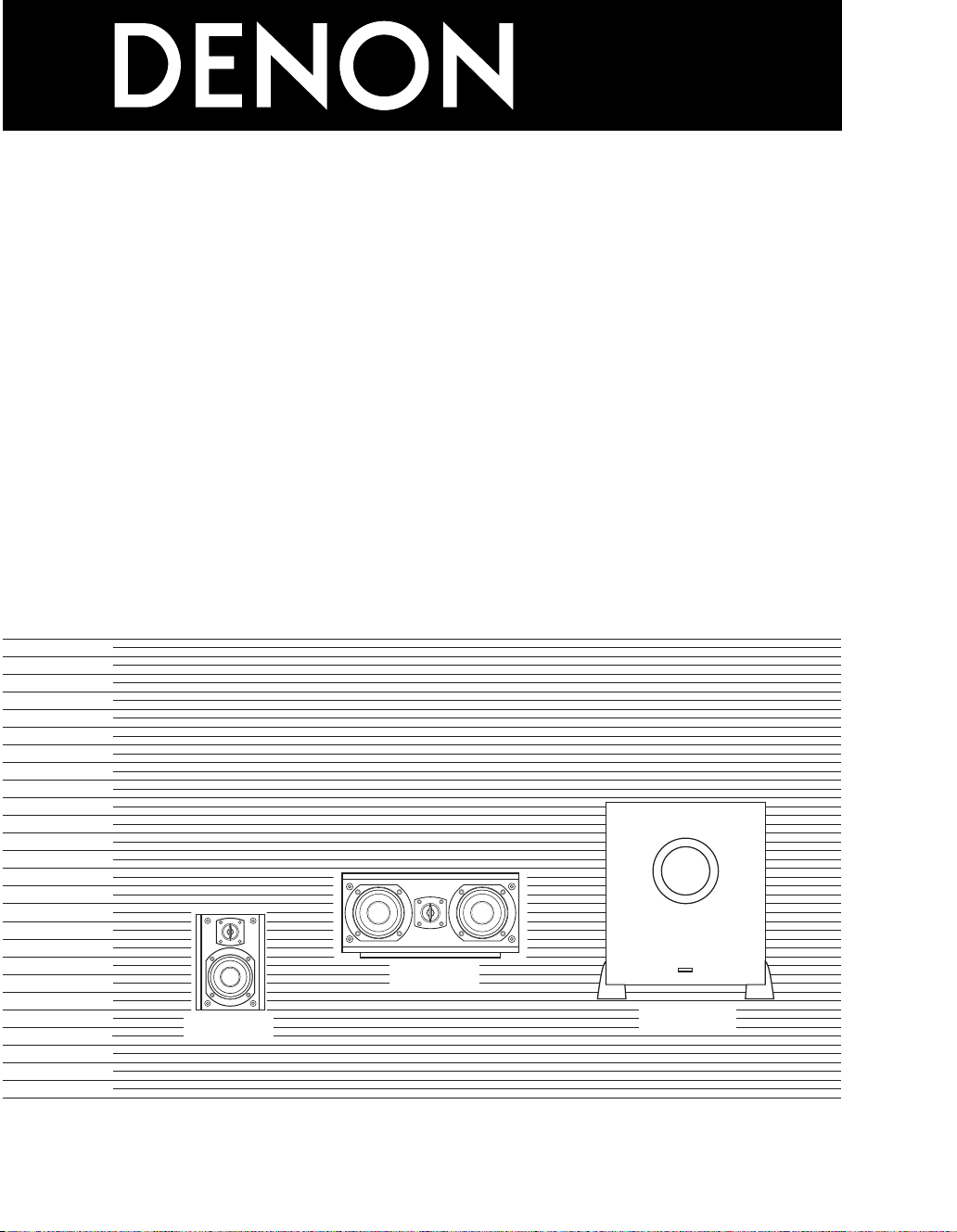
SPEAKER SYSTEM PACK
(SC-A65)
(SC-C65)
(DSW-65)
SYS-65HT
SYS-55HT
OPERATING INSTRUCTIONS
BEDIENUNGSANLEITUNG
MODE D’EMPLOI
ISTRUZIONI PER L’USO
INSTRUCCIONES DE OPERACION
GEBRUIKSAANWIJZING
FOR ENGLISH READERS PAGE 2 ~ 17
FÜR DEUTSCHE LESER SEITE 2 ~ 7, 18 ~ 27
POUR LES LECTEURS FRANCAIS PAGE 2 ~ 7, 28 ~ 37
PER IL LETTORE ITALIANO PAGINA 2 ~ 7, 38 ~ 47
PARA LECTORES DE ESPAÑOL PAGINA 2 ~ 7, 48 ~ 57
VOOR NEDERLANDSTALIGE LEZERS PAGINA 2 ~ 7, 58 ~ 67
Page 2
ENGLISH DEUTSCH FRANCAIS ITALIANO ESPAÑOL NEDERLANDS
2 SAFETY PRECAUTIONS
WARNING:
RISK OF ELECTRIC SHOCK
TO PREVENT FIRE OR SHOCK HAZARD, DO
NOT EXPOSE THIS APPLIANCE TO RAIN OR
MOISTURE.
CAUTION:
“SERIAL NO.
PLEASE RECORD UNIT SERIAL NUMBER
ATTACHED TO THE REAR OF THE CABINET FOR
FUTURE REFERENCE”
The lightning flash with arrowhead symbol, within an
equilateral triangle, is intended to alert the user to
CAUTION:
• The ventilation should not be impeded by covering the
ventilation openings with items, such as newspapers, tablecloths, curtains, etc.
• No naked flame sources, such as lighted candles, should be
placed on the apparatus.
• Please be care the environmental aspects of battery
disposal.
• The apparatus shall not be exposed to dripping or splashing
for use.
• No objects filled with liquids, such as vases, shall be placed
on the apparatus.
the presence of uninsulated “dangerous voltage”
within the product’s enclosure that may be of
sufficient magnitude to constitute a risk of electric
shock to persons.
The exclamation point within an equilateral triangle is
intended to alert the user to the presence of
important operating and maintenance (servicing)
instructions in the literature accompanying the
appliance.
CAUTION
DO NOT OPEN
TO REDUCE THE RISK OF
ELECTRIC SHOCK, DO NOT
REMOVE COVER (OR BACK).
NO USER-SERVICEABLE
PARTS INSIDE. REFER
SERVICING TO QUALIFIED
SERVICE PERSONNEL.
• DECLARATION OF CONFORMITY
We declare under our sole responsibility that this
product, to which this declaration relates, is in
conformity with the following standards:
EN60065, EN55013, EN55020, EN61000-3-2 and
EN61000-3-3.
Following the provisions of 73/23/EEC, 89/336/EEC and
93/68/EEC Directive.
• ÜBEREINSTIMMUNGSERKLÄRUNG
Wir erklären unter unserer Verantwortung, daß dieses
Produkt, auf das sich diese Erklärung bezieht, den
folgenden Standards entspricht:
EN60065, EN55013, EN55020, EN61000-3-2 und
EN61000-3-3.
Entspricht den Verordnungen der Direktive 73/23/EEC,
89/336/EEC und 93/68/EEC.
• DECLARATION DE CONFORMITE
Nous déclarons sous notre seule responsabilité que
l’appareil, auquel se réfère cette déclaration, est
conforme aux standards suivants:
EN60065, EN55013, EN55020, EN61000-3-2 et
EN61000-3-3.
D’après les dispositions de la Directive 73/23/EEC,
89/336/EEC et 93/68/EEC.
• FOR CANADA MODEL ONLY
CAUTION
TO PREVENT ELECTRIC SHOCK, MATCH WIDE
BLADE OF PLUG TO WIDE SLOT, FULLY INSERT.
• DICHIARAZIONE DI CONFORMITÀ
Dichiariamo con piena responsabilità che questo
prodotto, al quale la nostra dichiarazione si riferisce, è
conforme alle seguenti normative:
EN60065, EN55013, EN55020, EN61000-3-2 e
EN61000-3-3.
In conformità con le condizioni delle direttive 73/23/EEC,
89/336/EEC e 93/68/EEC.
• DECLARACIÓN DE CONFORMIDAD
Declaramos bajo nuestra exclusiva responsabilidad que
este producto al que hace referencia esta declaración,
está conforme con los siguientes estándares:
EN60065, EN55013, EN55020, EN61000-3-2 y
EN61000-3-3.
Siguiendo las provisiones de las Directivas 73/23/EEC,
89/336/EEC y 93/68/EEC.
• EENVORMIGHEIDSVERKLARING
Wij verklaren uitsluitend op onze verantwoordelijkheid
dat dit produkt, waarop deze verklaring betrekking heeft,
in overeenstemming is met de volgende normen:
EN60065, EN55013, EN55020, EN61000-3-2 en
EN61000-3-3.
Volgens de bepalingen van de Richtlijnen 73/23/EEC,
89/336/EEC en 93/68/EEC.
POUR LES MODELE CANADIEN UNIQUEMENT
•
ATTENTION
POUR ÉVITER LES CHOCS ÉLECTRIQUES,
INTERODUIRE LA LAME LA PLUS LARGE DE LA
FICHE DANS LA BORNE CORRESPONDANTE DE
LA PRISE ET POUSSER JUSQU’ AU FOND.
2
Page 3
ENGLISHDEUTSCHFRANCAISITALIANOESPAÑOLNEDERLANDS
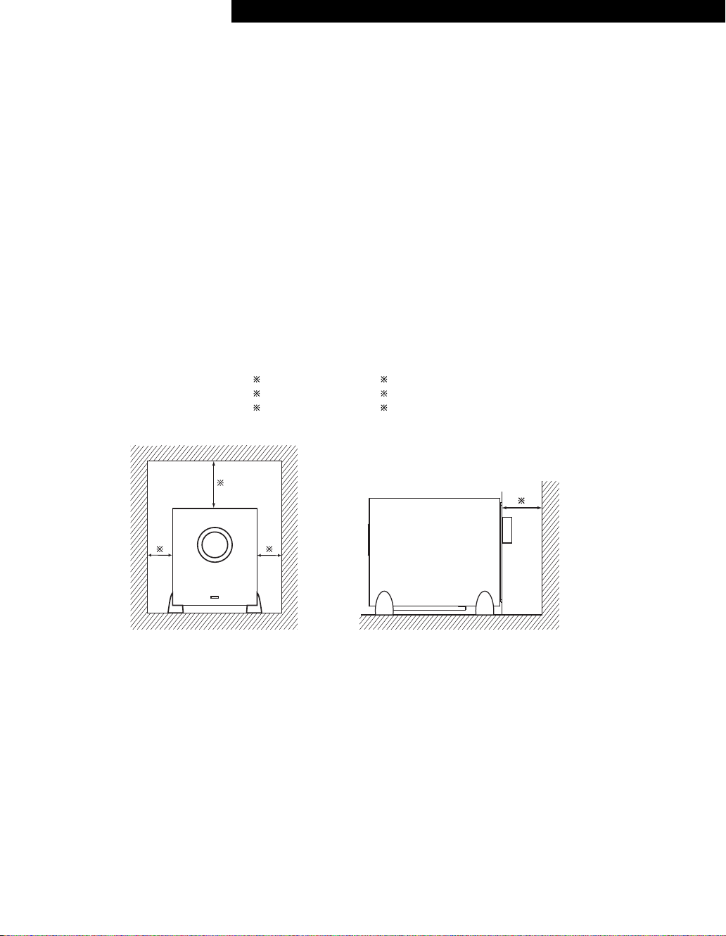
PRECAUTIONS FOR INSTALLATION
For heat dispersal, leave at least 10 cm of space
between the top, back and sides of this unit and the
wall or other components.
SICHERHEITSMASSNAHMEN BEIM EINBAU
Lassen Sie zur Wärmeverteilung mindestens 10 cm
Raum zwischen der Oberseite, der Rückseite und den
Seiten des Gerätes und der Wand oder anderen
Komponenten.
PRECAUTIONS D’INSTALLATION
Afin de disperser la chaleur, laisser un espace d’au
moins 10 cm entre le haut, l’arrière les côtés de cet
appareil et le mur ou un autre composant.
10cm or more
10cm oder mehr
10cm ou plus
PRECAUZIONI PER L’INSTALLAZIONE
Per consentire una buona dispersione del calore,
lasciate uno spazio di almeno 10 cm tra le parti
superiore, posteriore e laterali di quest’unità e le parete
o gli altri componenti.
PRECAUCIONES A TOMAR DURANTE LA INSTALACIÓN
Para que el calor se disipe, deje por lo menos 10 cm de
espacio entre las partes superior, posterior y laterales
de esta unidad y la pared u otros componentes.
VOORZORGSMAATREGELEN VOOR INSTALLATIE
Laat voor een goede warmteafvoer minstens 10 cm
ruimte tussen de boven-, achter- en zijkanten van dit
toestel en de muur of andere elementen.
10cm o più
10cm o más
10cm of meer
Wall
Wand
Mur
Parete
Pared
Muur
3
Page 4
ENGLISH DEUTSCH FRANCAIS ITALIANO ESPAÑOL NEDERLANDS
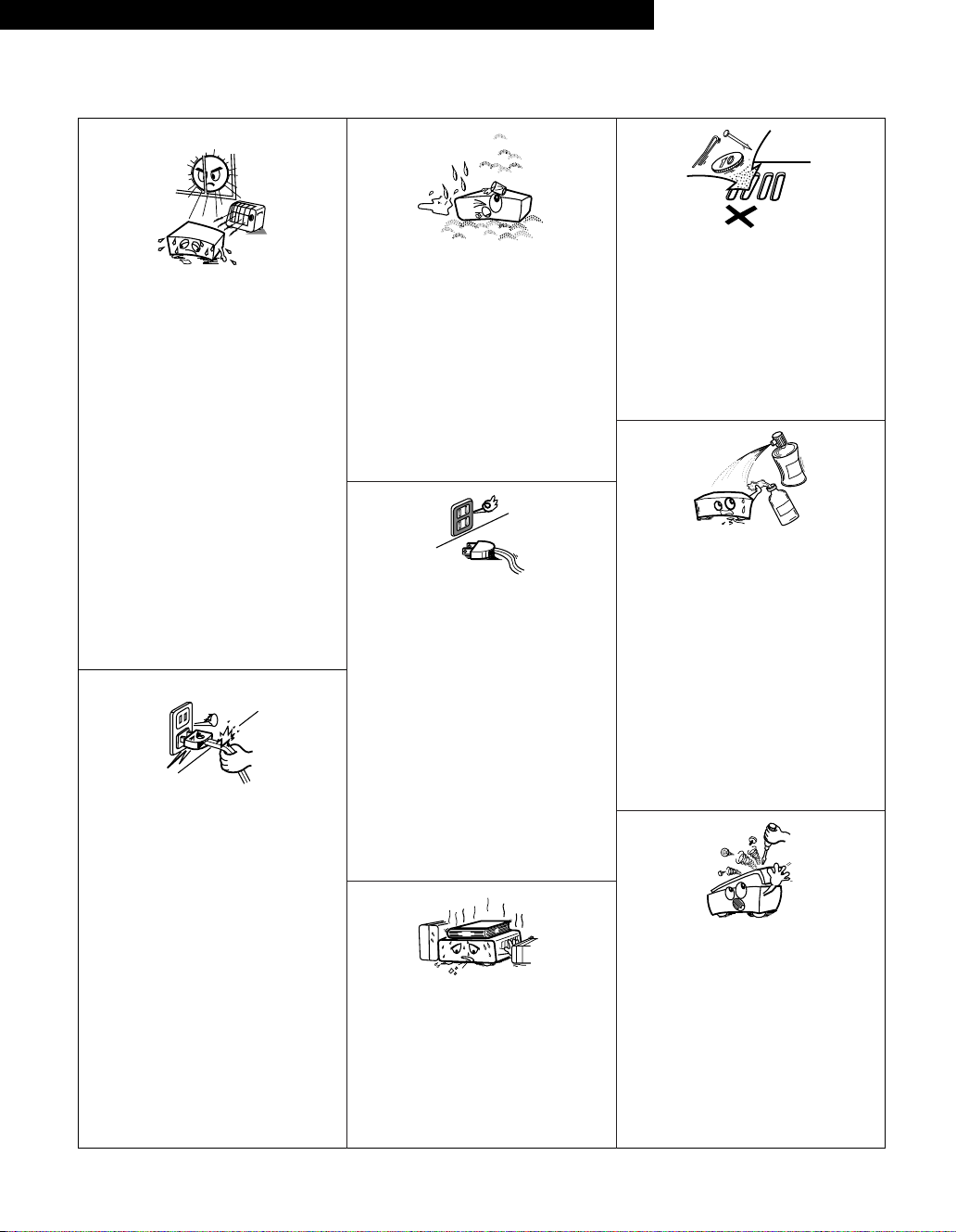
NOTE ON USE / HINWEISE ZUM GEBRAUCH / OBSERVATIONS RELATIVES A L’UTILISATION /
NOTE SULL’USO / NOTAS SOBRE EL USO / ALVORENS TE GEBRUIKEN
• Do not let foreign objects in the set.
• Keine fremden Gegenstände in das Gerät
kommen lassen.
• Ne pas laisser des objets étrangers dans
l’appareil.
• E’ importante che nessun oggetto è
inserito all’interno dell’unità.
• No deje objetos extraños dentro del
equipo.
• Laat geen vreemde voorwerpen in dit
apparaat vallen.
•Do not let insecticides, benzene, and
thinner come in contact with the set.
• Lassen Sie das Gerät nicht mit
Insektiziden, Benzin oder
Verdünnungsmitteln in Berührung
kommen.
• Ne pas mettre en contact des
insecticides, du benzène et un diluant
avec l’appareil.
• Assicuratevvi che l’unità non venga in
contatto con insetticidi, benzolo o
solventi.
• No permita el contacto de insecticidas,
gasolina y diluyentes con el equipo.
•Laat geen insektenverdelgende
middelen, benzine of verfverdunner met
dit apparaat in kontakt komen.
• Never disassemble or modify the set in
any way.
•Versuchen Sie niemals das Gerät
auseinander zu nehmen oder auf jegliche
Art zu verändern.
• Ne jamais démonter ou modifier
l’appareil d’une manière ou d’une autre.
• Non smontate mai, nè modificate l’unità
in nessun modo.
• Nunca desarme o modifique el equipo de
ninguna manera.
• Nooit dit apparaat demonteren of op
andere wijze modifiëren.
•Avoid high temperatures.
Allow for sufficient heat dispersion when
installed on a rack.
•Vermeiden Sie hohe Temperaturen.
Beachten Sie, daß eine ausreichend
Luftzirkulation gewährleistet wird, wenn
das Gerät auf ein Regal gestellt wird.
•Eviter des températures élevées
Tenir compte d’une dispersion de chaleur
suffisante lors de l’installation sur une
étagère.
• Evitate di esporre l’unità a temperature
alte.
Assicuratevi che ci sia un’adeguata
dispersione del calore quando installate
l’unità in un mobile per componenti
audio.
• Evite altas temperaturas.
Permite la suficiente dispersión del calor
cuando está instalado en la consola.
•Vermijd hoge temperaturen.
Zorg voor een degelijk hitteafvoer indien
het apparaat op een rek wordt geplaatst.
• Handle the power cord carefully.
Hold the plug when unplugging the cord.
• Gehen Sie vorsichtig mit dem Netzkabel
um.
Halten Sie das Kabel am Stecker, wenn
Sie den Stecker herausziehen.
• Manipuler le cordon d’alimentation avec
précaution.
Tenir la prise lors du débranchement du
cordon.
• Manneggiate il filo di alimentazione con
cura.
Agite per la spina quando scollegate il
cavo dalla presa.
• Maneje el cordón de energía con
cuidado.
Sostenga el enchufe cuando desconecte
el cordón de energía.
• Hanteer het netsnoer voorzichtig.
Houd het snoer bij de stekker vast
wanneer deze moet worden aan- of
losgekoppeld.
• Keep the set free from moisture, water,
and dust.
• Halten Sie das Gerät von Feuchtigkeit,
Wasser und Staub fern.
•Protéger l’appareil contre l’humidité,
l’eau et la poussière.
•Tenete l’unità lontana dall’umidità,
dall’acqua e dalla polvere.
• Mantenga el equipo libre de humedad,
agua y polvo.
• Laat geen vochtigheid, water of stof in
het apparaat binnendringen.
• Unplug the power cord when not using
the set for long periods of time.
•Wenn das Gerät eine längere Zeit nicht
verwendet werden soll, trennen Sie das
Netzkabel vom Netzstecker.
• Débrancher le cordon d’alimentation
lorsque l’appareil n’est pas utilisé
pendant de longues périodes.
• Disinnestate il filo di alimentazione
quando avete l’intenzione di non usare il
filo di alimentazione per un lungo periodo
di tempo.
• Desconecte el cordón de energía cuando
no utilice el equipo por mucho tiempo.
• Neem altijd het netsnoer uit het
stopkontakt wanneer het apparaat
gedurende een lange periode niet wordt
gebruikt.
✽ (For sets with ventilation holes)
• Do not obstruct the ventilation holes.
• Die Belüftungsöffnungen dürfen nicht
verdeckt werden.
• Ne pas obstruer les trous d’aération.
• Non coprite i fori di ventilazione.
• No obstruya los orificios de ventilación.
• De ventilatieopeningen mogen niet
worden beblokkeerd.
4
Page 5
SAFETY INSTRUCTIONS
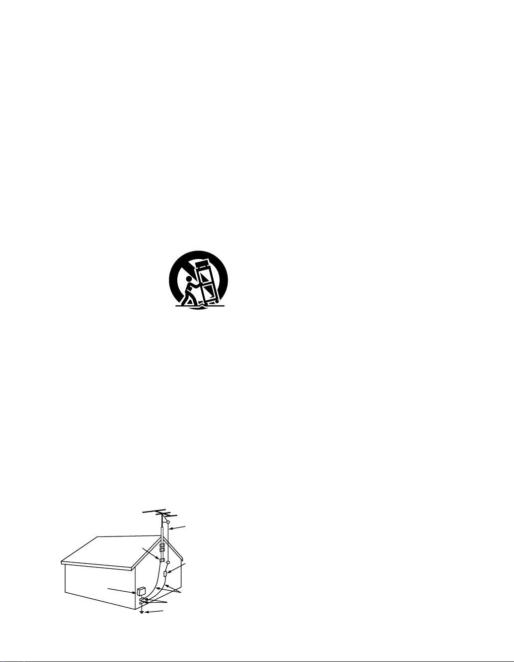
FIGURE A
EXAMPLE OF ANTENNA GROUNDING
AS PER NATIONAL
ELECTRICAL CODE
ANTENNA
LEAD IN
WIRE
GROUND
CLAMP
ELECTRIC
SERVICE
EQUIPMENT
ANTENNA
DISCHARGE UNIT
(NEC SECTION 810-20)
GROUNDING CONDUCTORS
(NEC SECTION 810-21)
GROUND CLAMPS
POWER SERVICE GROUNDING
ELECTRODE SYSTEM
(NEC ART 250, PART H)
NEC - NATIONAL ELECTRICAL CODE
1. Read Instructions – All the safety and operating instructions
should be read before the product is operated.
2. Retain Instructions – The safety and operating instructions
should be retained for future reference.
3. Heed Warnings – All warnings on the product and in the
operating instructions should be adhered to.
4. Follow Instructions – All operating and use instructions should
be followed.
5. Cleaning – Unplug this product from the wall outlet before
cleaning. Do not use liquid cleaners or aerosol cleaners.
6. Attachments – Do not use attachments not recommended by
the product manufacturer as they may cause hazards.
7. Water and Moisture – Do not use this product near water – for
example, near a bath tub, wash bowl, kitchen sink, or laundry
tub; in a wet basement; or near a swimming pool; and the like.
8. Accessories – Do not place this product on an unstable cart,
stand, tripod, bracket, or table. The product may fall, causing
serious injury to a child or adult, and serious damage to the
product. Use only with a cart, stand, tripod, bracket, or table
recommended by the manufacturer, or sold with the product.
Any mounting of the product should follow the manufacturer’s
instructions, and should use a
mounting accessory
recommended by the
manufacturer.
9. A product and cart
combination should be
moved with care. Quick
stops, excessive force,
and uneven surfaces may
cause the product and cart
combination to overturn.
10. Ventilation – Slots and openings in the cabinet are provided for
ventilation and to ensure reliable operation of the product and
to protect it from overheating, and these openings must not be
blocked or covered. The openings should never be blocked by
placing the product on a bed, sofa, rug, or other similar
surface. This product should not be placed in a built-in
installation such as a bookcase or rack unless proper
ventilation is provided or the manufacturer’s instructions have
been adhered to.
11. Power Sources – This product should be operated only from
the type of power source indicated on the marking label. If
you are not sure of the type of power supply to your home,
consult your product dealer or local power company. For
products intended to operate from battery power, or other
sources, refer to the operating instructions.
12. Grounding or Polarization – This product may be equipped with
a polarized alternating-current line plug (a plug having one
blade wider than the other). This plug will fit into the power
outlet only one way. This is a safety feature. If you are unable
to insert the plug fully into the outlet, try reversing the plug. If
the plug should still fail to fit, contact your electrician to replace
your obsolete outlet. Do not defeat the safety purpose of the
polarized plug.
13. Power-Cord Protection – Power-supply cords should be routed
so that they are not likely to be walked on or pinched by items
placed upon or against them, paying particular attention to
cords at plugs, convenience receptacles, and the point where
they exit from the product.
15. Outdoor Antenna Grounding – If an outside antenna or cable
system is connected to the product, be sure the antenna or
cable system is grounded so as to provide some protection
against voltage surges and built-up static charges. Article 810
of the National Electrical Code, ANSI/NFPA 70, provides
information with regard to proper grounding of the mast and
supporting structure, grounding of the lead-in wire to an
antenna discharge unit, size of grounding conductors, location
of antenna-discharge unit, connection to grounding electrodes,
and requirements for the grounding electrode. See Figure A.
16. Lightning – For added protection for this product during a
lightning storm, or when it is left unattended and unused for
long periods of time, unplug it from the wall outlet and
disconnect the antenna or cable system. This will prevent
damage to the product due to lightning and power-line surges.
17. Power Lines – An outside antenna system should not be
located in the vicinity of overhead power lines or other electric
light or power circuits, or where it can fall into such power
lines or circuits. When installing an outside antenna system,
extreme care should be taken to keep from touching such
power lines or circuits as contact with them might be fatal.
18. Overloading – Do not overload wall outlets, extension cords, or
integral convenience receptacles as this can result in a risk of
fire or electric shock.
19. Object and Liquid Entry – Never push objects of any kind into
this product through openings as they may touch dangerous
voltage points or short-out parts that could result in a fire or
electric shock. Never spill liquid of any kind on the product.
20.
Servicing – Do not attempt to service this product yourself
as opening or removing covers may expose you to
dangerous voltage or other hazards. Refer all servicing to
qualified service personnel.
21.
Damage Requiring Service – Unplug this product from the
wall outlet and refer servicing to qualified service
under the following conditions:
a) When the power-supply cord or plug is damaged,
b) If liquid has been spilled, or objects have fallen into the
product,
c) If the product has been exposed to rain or water,
d) If the product does not operate normally by following the
operating instructions. Adjust only those controls that are
covered by the operating instructions as an improper
adjustment of other controls may result in damage and will
often require extensive work by a qualified technician to
restore the product to its normal operation,
e) If the product has been dropped or damaged in any way,
and
f) When the product exhibits a distinct change in performance
– this indicates a need for service.
22. Replacement Parts – When replacement parts are required, be
sure the service technician has used replacement parts
specified by the manufacturer or have the same characteristics
as the original part. Unauthorized substitutions may result in
fire, electric shock, or other hazards.
23. Safety Check – Upon completion of any service or repairs to
this product, ask the service technician to perform safety
checks to determine that the product is in proper operating
condition.
24. Wall or Ceiling Mounting – The product should be mounted to
a wall or ceiling only as recommended by the manufacturer.
25. Heat – The product should be situated away from heat sources
such as radiators, heat registers, stoves, or other products
(including amplifiers) that produce heat.
personnel
5
Page 6

ENGLISH DEUTSCH FRANCAIS ITALIANO ESPAÑOL NEDERLANDS
2 CONTENTS SYS-65HT
1. Satellite speaker system (SC-A65) ...........................5
2. Center speaker system (SC-C65) .............................1
3. Active subwoofer (DSW-65) .....................................1
4. BASE ........................................................................1
5. Cord A (10 m) ...........................................................6
6. Cord B (3 m RCA PIN) ..............................................1
7. Anti-slip pad (4 pcs. / 1 sheet) ..................................5
8. Operating instructions ..............................................1
9. DENON Service network..........................................1
2 INHALT SYS-65HT
1. Satelliten-Lautsprechersystem (SC-A65) ..................5
2. Center-Lautsprechersystem (SC-C65) ......................1
3. Angesteuerter Subwoofer (DSW-65)........................1
4. Fuß ...........................................................................1
5. Kabel A (10 m) ..........................................................6
6. Kabel B (3 m RCA-Stiftstecker).................................1
7. Antirutsch-Unterlage (4 St. / 1 Bogen)......................5
8. Opera Bedienungsanleitung .....................................1
9. DENON-Servicenetzwerk .........................................1
2 CONTENU SYS-65HT
1. Haut-parleur multivoie satellite (SC-A65) ..................5
2. Haut-parleur multivoie centralisé (SC-C65) ...............1
3. Enceinte d’extrêmes graves active (DSW-65) ..........1
4. LA BASE ...................................................................1
5. Cordon électrique A (10 m).......................................6
6. Cordon électrique B (3 m,broche RCA) ....................1
7. Pavé antidérapant (4 pavés / 1 feuille) ......................5
8. Mode d’emploi .........................................................1
9. Liste des points de service après-vente DENON .....1
2 CONTENUTO SYS-65HT
1. Sistema altoparlante satellite (SC-A65).....................5
2. Sistema altoparlante centrale (SC-C65) ....................1
3. Subwoofer attivo (DSW-65)......................................1
4. BASE ........................................................................1
5. Cavo A (10 m) ...........................................................6
6. Cavo B (3 m,RCA PIN) ..............................................1
7. Antiscivolo (4 pezzi / 1 foglio) ...................................5
8. Istruzioni per l’uso ....................................................1
9. Rete Assistenza DENON ..........................................1
2 CONTENIDO SYS-65HT
1. Sistema de altavoz satélite (SC-A65) ........................5
2. Sistema de altavoz central (SC-C65).........................1
3. Subwoofer activo (DSW-65) .....................................1
4. LA BASE ...................................................................1
5. Cable A (10 m) ..........................................................6
6. Cable B (3 m RCA PIN) .............................................1
7. Alfombrilla antideslizante (4 pzas. / 1 hoja) ...............5
8. Instrucciones de operación.......................................1
9. Red de servicio DENON ...........................................1
2 INHOUD SYS-65HT
1. Satellietluidsprekersysteem (SC-A65) ......................5
2. Middenluidsprekersysteem (SC-C65) .......................1
3. Actieve subwoofer (DSW-65) ...................................1
4. BASES ......................................................................1
5. Snoer A (10 meter) ...................................................6
6. Snoer B (3 meter,RCA tulp) ......................................1
7. Anti-slipkussentje (4 stuks / 1 vel) ............................5
8. Gebruiksaanwijzing...................................................1
9. DENON service-netwerk ..........................................1
6
Page 7

ENGLISHDEUTSCHFRANCAISITALIANOESPAÑOLNEDERLANDS
2 CONTENTS SYS-55HT
1. Satellite speaker system (SC-A65) ...........................4
2. Center speaker system (SC-C65) .............................1
3. Active subwoofer (DSW-65) .....................................1
4. BASE ........................................................................1
5. Cord A (10 m) ...........................................................5
6. Cord B (3 m RCA PIN) ..............................................1
7. Anti-slip pad (4 pcs. / 1 sheet) ..................................4
8. Operating instructions ..............................................1
9. DENON Service network..........................................1
2 INHALT SYS-55HT
1. Satelliten-Lautsprechersystem (SC-A65) ..................4
2. Center-Lautsprechersystem (SC-C65) ......................1
3. Angesteuerter Subwoofer (DSW-65)........................1
4. Fuß ...........................................................................1
5. Kabel A (10 m) ..........................................................5
6. Kabel B (3 m RCA-Stiftstecker).................................1
7. Antirutsch-Unterlage (4 St. / 1 Bogen)......................4
8. Opera Bedienungsanleitung .....................................1
9. DENON-Servicenetzwerk .........................................1
2 CONTENU SYS-55HT
1. Haut-parleur multivoie satellite (SC-A65) ..................4
2. Haut-parleur multivoie centralisé (SC-C65) ...............1
3. Enceinte d’extrêmes graves active (DSW-65) ..........1
4. LA BASE ...................................................................1
5. Cordon électrique A (10 m).......................................5
6. Cordon électrique B (3 m,broche RCA) ....................1
7. Pavé antidérapant (4 pavés / 1 feuille) ......................4
8. Mode d’emploi .........................................................1
9. Liste des points de service après-vente DENON .....1
2 CONTENUTO SYS-55HT
1. Sistema altoparlante satellite (SC-A65).....................4
2. Sistema altoparlante centrale (SC-C65) ....................1
3. Subwoofer attivo (DSW-65)......................................1
4. BASE ........................................................................1
5. Cavo A (10 m) ...........................................................5
6. Cavo B (3 m,RCA PIN) ..............................................1
7. Antiscivolo (4 pezzi / 1 foglio) ...................................4
8. Istruzioni per l’uso ....................................................1
9. Rete Assistenza DENON ..........................................1
2 CONTENIDO SYS-55HT
1. Sistema de altavoz satélite (SC-A65) ........................4
2. Sistema de altavoz central (SC-C65).........................1
3. Subwoofer activo (DSW-65) .....................................1
4. LA BASE ...................................................................1
5. Cable A (10 m) ..........................................................5
6. Cable B (3 m RCA PIN) .............................................1
7. Alfombrilla antideslizante (4 pzas. / 1 hoja) ...............4
8. Instrucciones de operación.......................................1
9. Red de servicio DENON ...........................................1
2 INHOUD SYS-55HT
1. Satellietluidsprekersysteem (SC-A65) ......................4
2. Middenluidsprekersysteem (SC-C65) .......................1
3. Actieve subwoofer (DSW-65) ...................................1
4. BASES ......................................................................1
5. Snoer A (10 meter) ...................................................5
6. Snoer B (3 meter,RCA tulp) ......................................1
7. Anti-slipkussentje (4 stuks / 1 vel) ............................4
8. Gebruiksaanwijzing...................................................1
9. DENON service-netwerk ..........................................1
7
Page 8
ENGLISH
CAUTIONS ON HANDLING
When installing, carefully examine the place and method of installation for safety.
When using a stand, brackets, etc., follow the instructions included with the stand or brackets and check for safety
before installing and using. Denon will accept no responsibility for damages or accidents caused by the unit falling.
Cautions on Installation – Speaker System (SC-A65, SC-C65)
The quality of the sound produced from the
speaker system is affected by the size and type
(Japanese or Western) of the room, as well as by
the method of installation. Consider the points
listed below before installing the speaker system.
2 Note that placing the speaker system on the same
stand or shelf as a record player may result in
howling.
2 If there is a wall, glass door, etc., directly in front of
or behind the speaker system, cover the wall or door
with a thick curtain to prevent resonance and
reflection.
2 The SC-A65 and SC-C65 speaker systems are of the
low-leakage-flux type and can be used near
televisions, but depending on the TV there may be
color blotching on the picture. If this happens, turn
off the TV’s power, wait 15 to 30 minutes, then turn
the TV’s power back on. The TV’s automatic
degaussing circuit should reduce the blotching on
the picture. If blotching persists, move the speaker
further away.
2 The center speaker (SC-C65) is equipped with anti-
slip pads upon shipment from the factory. If
necessary, however, also apply the included anti-slip
pads (cork, approximately 1 mm thick).
2
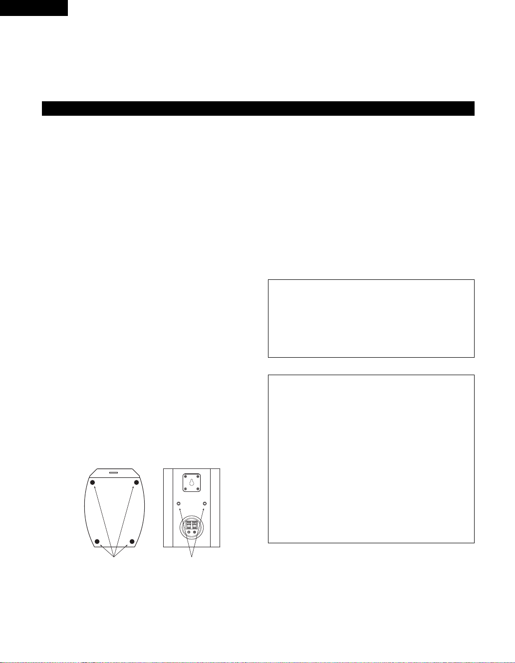
When placing the satellite speaker system (SC-A65)
on a stand, etc., stick the included anti-slip pads (cork,
approximately 1 mm thick) at the four corners of the
bottom surface. (Refer to the illustration below.)
[
Satellite speaker system (illustration of bottom of SC-A65)
2 When mounting the satellite speaker system (SC-
A65) on a stand or bracket, M5 nuts are inserted into
the bottom of the satellite speaker system (SC-A65)
at intervals of 60 mm. When mounting, following the
instructions in the manual included with the speaker
stand or ceiling mount bracket, and be sure to install
properly and securely.
2 When the satellite speaker system (SC-A65) is
mounted on a ceiling mount bracket, it is turned
upside down due to the installation angle. The
Denon mark is also turned upside down, so detach
the speaker net and reattach it in the opposite
direction.
CAUTION:
•To ensure safety, do not place any objects on top
or lean objects against the speaker system.
• The speaker may topple down or fall if force is
applied to the sides. Be particularly careful to
avoid this, as this could cause injury or other
serious accidents.
WARNING:
• When installing the speaker systems on the
ceiling or wall, to ensure safety, have specialists
do the installation work.
• Be sure to fasten the speaker cords to a wall,
etc., to prevent people from tripping over them or
otherwise pulling on them accidentally, causing
]
the speaker systems to fall.
• Be sure to check for safety after installing the
speaker systems. Afterwards, perform safety
inspections at regular intervals to be sure there is
no danger that the speaker systems will fall.
Denon will accept no responsibility for damages
or accidents caused by inappropriate choice of
the place of installation or improper installation
procedures.
Anti-slip pads
(1 mm thick)
[
Bottom
Speaker stand/speaker
bracket mount screw holes
]
[
Rear
]
8
Page 9
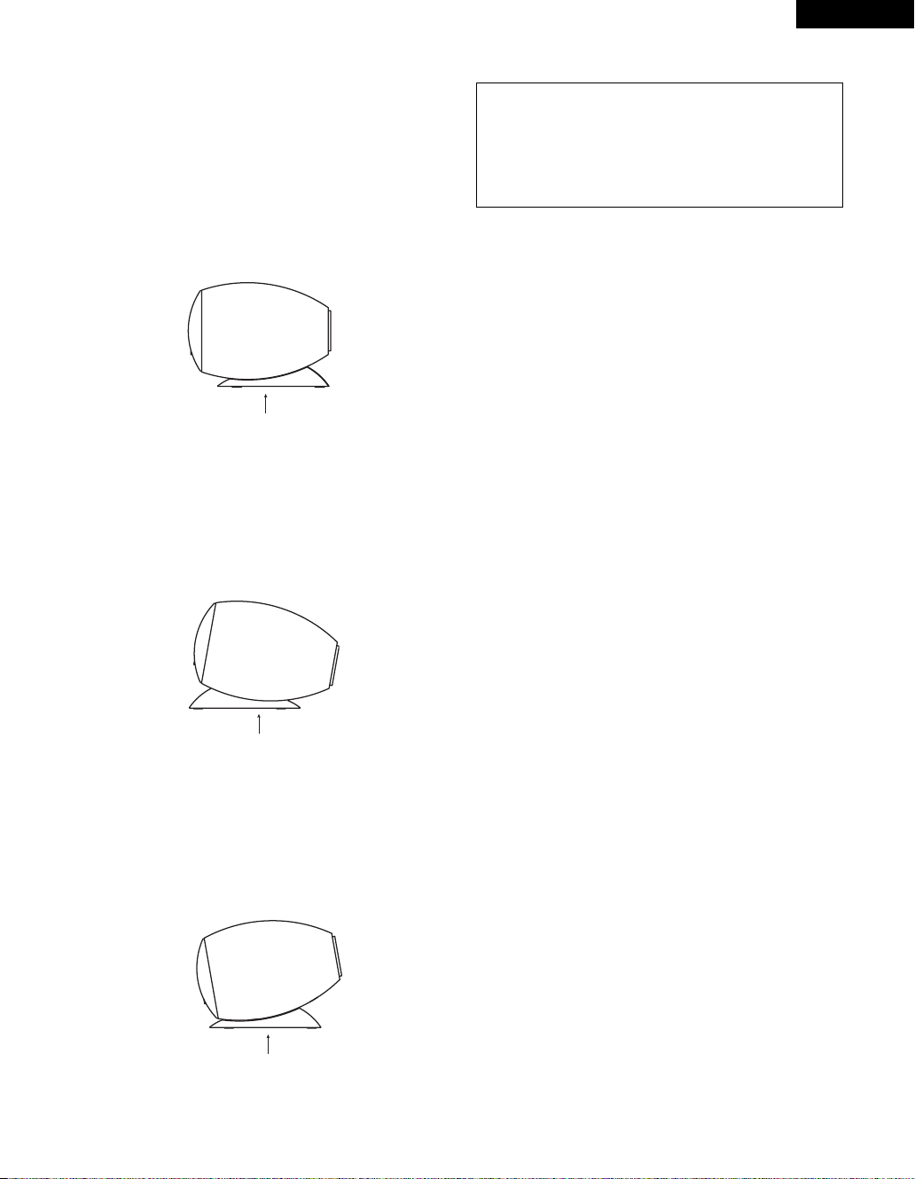
2 Speaker syatem (SC-C65)
• The included base can be used to set the speaker
systems (SC-C65) at one of three angles: level,
slanting upward or slanting down ward.
To set the speaker system level
Use the included base and set as shown on the
diagram below.
In this case, do not use the four included anti-slip
pads (pieces of cork 1 mm thick).
[
Speaker system (SC-C65) side view
]
Included base
To set the speaker system at an angle slanting
upwards
Use the included base and set as shown on the
diagram below.
In this case, do not use the four included anti-slip
pads (pieces of cork 1 mm thick).
ENGLISH
CAUTION:
• Use the included base and set in a firm stable
place.
• If the speaker system is set in an unstable place,
it could tip over or fall, possibly resulting in
serious accidents.
[
Speaker system (SC-C65) side view
]
Included base
To set the speaker system at an angle slanting
down wards
Use the included base and set as shown on the
diagram below.
In this case, do not use the four included anti-slip
pads (pieces of cork 1 mm thick).
[
Speaker system (SC-C65) side view
]
Included base
9
Page 10

ENGLISH
CAUTIONS ON HANDLING (continued)
Other Cautions (SC-A65, SC-C65)
2 Note that color blotching may occur on a TV, etc., due to interaction with the speaker system if there is a magnet
or an object generating magnetic force nearby.
Examples: (a) When there are magnets on the door of the rack, stand, etc.
(b) When a health device, etc., equipped with magnets is placed nearby.
(c) When toys or other objects using magnets are placed nearby.
2 Note that the illustrations in this instructions may differ from the actual set for explanation purposes.
2 Be sure to keep the operating instructions.
After reading these operating instructions, store them in a safe place. We also recommend filling in the
necessary items on the back cover.
Cautions on Installation – Active subwoofer (DSW-65)
2 Note that placing the active subwoofer on the same stand or shelf as a record player may result in howling.
2 The DSW-65 active subwoofer is a Lowleakage-Flux type speaker system and can be used near televisions, but
depending on the TV there may be color blotching on the picture. If this happens, turn off the TV’s power, move
the TV and subwoofer a little apart, wait 15 to 30 minutes, then turn the TV’s power back on. The TV’s automatic
degaussing circuit should reduce the blotching on the picture. If blotching persists, move the subwoofer and TV
further away from each other.
2 Install on a firm, flat floor to prevent accidents due to toppling down.
2 Do not place a record player, CD player or other AV device on top of the active subwoofer.
Other Cautions – Active subwoofer (DSW-65)
2 The built-in amplifier of the active subwoofer (DSW-65) includes a muting circuit. The output signal is strongly
attenuated for several seconds after the power is turned on. If the volume is adjusted during this time, the output
may be extremely high when the muting circuit is deactivated. Be sure to wait for the muting circuit to be
deactivated before adjusting the volume.
2 Note that color blotching may occur on a TV, etc., due to interaction with the subwoofer if there is a magnet or an
object generating magnetic force nearby.
Examples: (a) When there are magnets on the door of the rack, stand, etc.
(b) When a health device, etc., equipped with magnets is placed nearby.
(c) When toys or other objects using magnets are placed nearby.
2 Note that the illustrations in this instructions may differ from the actual set for explanation purposes.
2 Be sure to keep the operating instructions.
After reading these operating instructions, store them in a safe place. We also recommend filling in the
necessary items on the back cover.
WARNING:
• Be sure to fasten the power cord to a wall, etc., to prevent people from tripping over it or otherwise pulling on
it accidentally, causing the subwoofer to fall.
10
Page 11

PART NAMES AND FUNCTIONS
z
x
c
v
b
n
m
,
.
Active subwoofer (DSW-65) rear panel
ENGLISH
Line input connector (LINE IN)
z
• Connect this to the AV amplifier’s pre-out
connector (“SUBWOOFER”, “MONO OUT”,
etc.) using the included connection cord (3-meter
RCA pin cord).
Line output connector (LINE OUT)
x
• The signal input to the line input connector is
output as such from here in parallel.
• When using two active subwoofers, connect the
other active subwoofer’s line input connector to
this connector.
Phase selector switch (PHASE)
c
• This switches the phase of the output signal with
respect to the input signal.
• Normally use the active subwoofer with this
switch set at the “NORM.” position. If the
continuity between the sound of the active
subwoofer and the left and right speakers seems
unnatural, try switching to the “REV.” position,
and set the switch to the position in which the
sound is most natural.
LF direct switch (LF DIRECT)
v
• When using the active subwoofer connected to a
Dolby Digital or dts-compatible AV amplifier, if
this function is turned on the signals bypass the
active subwoofer’s crossover and volume
adjustment circuits, resulting in purer, higher
quality sound. Note that when this is done the
crossover adjustment control (b) and volume
adjustment control (n) will no longer function.
Crossover adjustment control (CROSSOVER)
b
• This control only functions when the LF DIRECT
switch (v) is set to the “OFF” position.
• This control sets the upper limit of the
frequencies reproduced by the active subwoofer.
• Setting criteria
50Hz : For left/right speakers with diameters of
20 cm or greater
100Hz : For left/right speakers with diameters
between 10 and 25 cm
200Hz : For left/right speakers with diameters of
12 cm or less
• When using a Dolby Digital or dts-compatible AV
amplifier, we recommend turning the LF DIRECT
switch (v) to the “ON” position and not using
this function.
“Dolby” is a trademark of the Dolby Laboratories
Licensing Corporation.
“dts” is a trademark of Digital Theater Systems.
11
Page 12

ENGLISH
PART NAMES AND FUNCTIONS (continued)
About the AV amplifier’s crossover frequency
selection
The crossover frequency of the satellite
speaker/center speaker and the active
subwoofer (the boundary between the
frequency range produced by the active
subwoofer and the other speakers) is set on the
connected AV amplifier, and is usually fixed at
between 80 and 120 kHz.
With some amplifiers, however, including the
Denon AV amplifier, this frequency can be
selected. When using this type of amplifier, the
crossover frequency can be selected to suit your
tastes.
When using the DSW-65 active subwoofer with
this type of amplifier, a richer sound can be
achieved by setting the crossover frequency to
around 150 Hz. Adjust the crossover frequency
to suit your tastes. For instructions on switching,
refer to your amplifier’s operating instructions.
When connecting to a Dolby Digital or dtscompatible AV amplifier, whether one on which
the crossover frequency is fixed or one on which
it can be adjusted, we recommend setting the
LF DIRECT switch of the active subwoofer
(DSW-65) to the “ON” position.
Volume adjustment control (LEVEL)
n
• This control only functions when the LF DIRECT
switch (v) is set to the “OFF” position.
• Use this control to adjust the volume of the
active subwoofer.
• When turned clockwise ( ) from the center
position, the volume of the active subwoofer
increases, and when turned counterclockwise
( ), the volume decreases. Set to the desired
position.
• For some signals, a very soft sound will be
produced even when the volume adjustment
control(“LEVEL”) is turned fully counterclockwise
() and set to the minimum (“MIN”). This is not
a malfunction.
If this should happen, connect the cord
connected to the set’s LINE IN connector to an
output connector (SUB WOOFER PRE OUT,
MONO OUT, etc.) for which the signals pass
through the master volume circuitry of the AV
surround amplifier, etc., before being output.
Use the set’s volume adjustment control
(“LEVEL”) to adjust the volume difference with
the speakers other than the super woofer (front,
center, surround, etc.), and adjust the overall
volume using the master volume control on the
AV surround amplifier, etc.
Auto standby selector switch (AUTO STANDBY)
m
ON : The auto standby function is activated
OFF : The auto standby function is deactivated
Auto Standby Function
• The amplifier is automatically set to the
standby mode if no signal is input for 5 to 11
minutes, thereby saving electricity.
The power turns on immediately when a signal
is input.
Status indicator
,
• The two-colored LED indicates the active
subwoofer’s operating status, as follows:
Power “ON”......................................Lights green
Auto power off (standby mode).............Lights red
Power “OFF” ............................................LED off
Protective circuit activated.................Flashing red
Power switch (POWER)
.
• The power turns on when this switch is set to
the “ON” position.
• Several seconds are required for the set to begin
operating. This is because the set includes a
built-in muting circuit to prevent noise when the
power switch is turned on and off.
• When set to the “OFF” position, the power turns
off.
12
Page 13

ENGLISH
CONNECTIONS
CAUTION:
• Do not plug the AC power cord into an AC power outlet until all connections have been completed.
• Check the left and right channels and be sure to interconnect them properly, L (left) to L, R (right) to R.
•Plug the AC power cord in securely. An insecure connection could cause noise.
• Note that clamping pin-plug cords and power cords together or running pin-plug cords near the power
transformer could result in humming or noise.
• Check the polarities of the speakers and amplifier and be sure to interconnect properly. Connect the red
terminal on the speaker to the “+” speaker terminal on the amplifier, the black terminal on the speaker to the
“–” speaker terminal on the amplifier.
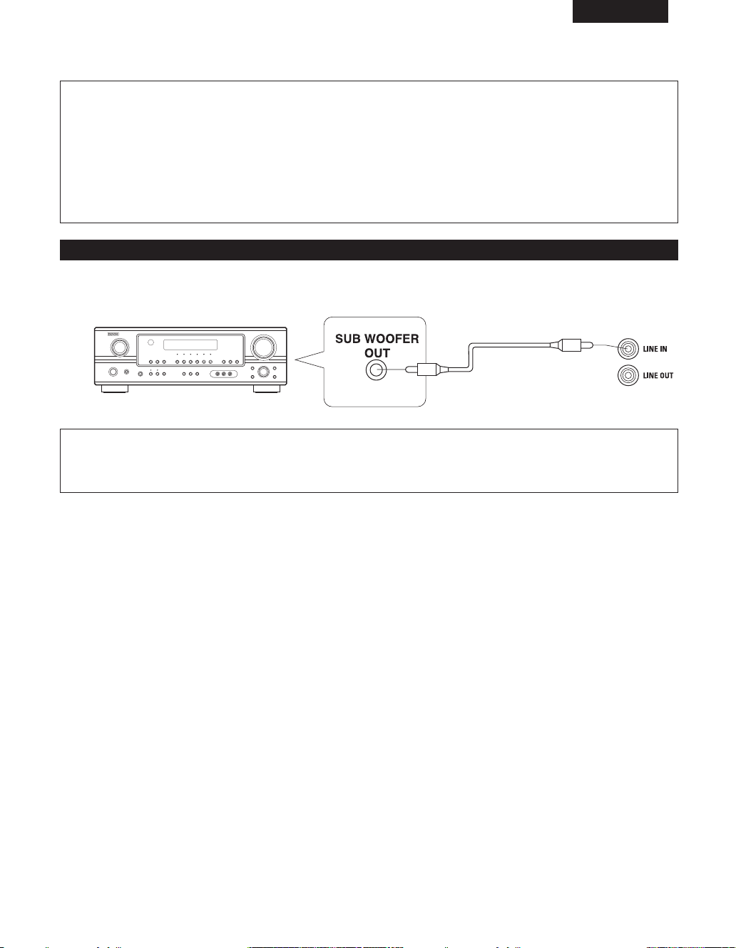
(1) Connecting the line input connector (LINE IN)
* Connect this to the pre-out connector for the active subwoofer on the AV amplifier (“SUBWOOFER PREOUT”,
“MONO OUT”, etc.) using the included connection cord
(3-meter RCA pin cord).
Active subwoofer (DSW-65)
Included connection cord
(3-meter RCA pin cord)
CAUTION:
• If this connector is connected to the pre-out connector for the surround center channel of a stereo amplifier or
AV surround amplifier, only the center channel’s bass sound will be produced, so the overall bass sound will be
insufficient.
13
Page 14

ENGLISH
CONNECTIONS (continued)
(2) Connecting the speaker terminals
* Read the amplifier’s operating instructions carefully before connecting, and be sure to use properly.
* When connecting the equipment or changing the connections, be sure to turn the equipment’s power switches
off and unplug the power plugs from the AC power outlets.
2 Connecting the speaker terminals
1. Peel off the sheath from the tip of the connection cord, then firmly twist the wires by hand so that they do not
stick out and cause short-circuits.
2. Press and lower the lever, and insert the cord’s core wire into the hole.
3. Release the lever.
Gently pull on the connection cord to check that it is firmly connected.
1
To “–” side on amplifier (silver colored
core wire)
Once the connections are completely, gently pull on the speaker cords to make sure they are securely
connected.
CAUTION:
• Be careful to interconnect the positive (“+”, red) and negative (“–”, black) sides and the left and right speakers
properly.
• Connect the side of the included connection cord with the copper colored core wires to the red speaker
terminal.
•To prevent circuit problems, never short-circuit copper and silver colored core wires or the left and right cords.
Sheath 2
The red side is the “+” side, the black
side the “–” side.
To “+” side on amplifier (copper colored
core wire)
NOTE: Make sure the core wires do not
touch each other.
3
When installing, carefully examine the place and method of installation for safety.
When using a stand, brackets, etc., follow the instructions included with the stand or brackets and check for
safety before installing and using. Denon will accept no responsibility for damages or accidents caused by the
unit falling.
14
Page 15

ENGLISH
USING THE ACTIVE SUBWOOFER (DSW-65)
1. Set the power switch to the “ON” position.
• When the unit’s AC power cord is plugged into a switched AC outlet on the amplifier, if the power switch is left
at the “ON” position, the unit’s power turns on and off automatically when the amplifier’s power is turned on
and off.
• If the AC power cord is not plugged into a switched AC outlet on the amplifier, set the unit’s power switch to
the “ON” position after turning on the amplifier’s power. When turning the power off, set the unit’s power
switch to the “OFF” position before turning off the amplifier’s power.
2. Adjust the volume using the volume adjustment control.
For details, see “PART NAMES AND FUNCTIONS”.
REMOVING THE SPEAKER NET (SC-A65, SC-C65)
* The net on the front of the speaker systems (SC-A65, SC-C65) can be removed.
•To remove, grasp both sides of the net and pull forward.
•To mount, line up the holes in the four corners of the speaker net with the projecting pieces in the four corners of
the cabinet and press in.
15
Page 16

ENGLISH
TROUBLESHOOTING
Troubleshooting
2 Are the connections proper?
2 Are you operating correctly as describe in the operating instructions?
2 Are the amplifier and player(s) operating properly?
If the set does not operate properly, check the items on the table below. If this does not solve the problem, the set
may be out of order. Turn off the power, unplug the AC power cord from the AC power outlet, then contact your
store of purchase. If your store of purchase cannot help you, please contact your Denon nearest authorized service
network.
Symptom
Active subwoofer (DSW-65):
LED does not light and no sound is
produced when power is turned on.
Active subwoofer (DSW-65):
LED lights but no sound is
produced.
Active subwoofer (DSW-65):
LED flashes and no sound is
produced.
Active subwoofer (DSW-65):
Sound is distorted.
Active subwoofer (DSW-65):
Oscillation (loud continuous sound
produced).
Cause Remedy
• AC power plug is not securely
connected.
•
Cords are not securely connected.
•Volume adjustment control is
turned all the way down.
•Protective circuit has been
activated due to excess input or
rise in temperature.
•Volume level is too high.
• Sound is being distorted on
connected amplifier.
•Volume of active subwoofer or
amplifier set too high.
• Check the connection of the AC
power plug.
• Connect securely.
•Turn the control and set it to the
desired position.
• Set the power switch to the
“OFF” position, wait at least 1
minute, then set the power
switch back to the “ON” position.
If the problem persists, unplug
the AC power cord from the AC
power outlet and contact your
store of purchase.
•Turn the volume adjustment
control counterclockwise to lower
the volume.
• Do not amplify the bass sound on
the amplifier. (Lower the
amplifier’s bass adjustment
control or volume.)
• Lower the volume of the active
subwoofer or amplifier.
For improvement purposes, specifications and design are subject to change without notice.
16
Page 17

SPECIFICATION
Satellite speaker system (SC-A65)
Type: 2-way, 2-speakers
Closed box / Low-leakage-flux
Speakers: 9 cm cone bass-mid x 1
2.5 cm super-high range x 1
Input impedance: 6 Ω/ohms
Max. input: 40 watts (IEC)
100 watts (PEAK)
Crossover frequency: 6 kHz
Frequency range: 60 Hz ~ 22 kHz
Dimensions: 130(W) x 180 (H) x 171 (D) mm
Mass: 1.2 kg
Center speaker system (SC-C65)
Type: 2-way, 3-speakers
Closed box / Low-leakage-flux
Speakers: 9 cm cone bass-mid x 2
2.5 cm super-high range x 1
Input impedance: 6 Ω/ohms
Max. input: 40 watts (IEC)
100 watts (PEAK)
Crossover frequency: 6 kHz
Frequency range: 60 Hz ~ 22 kHz
Dimensions: 290 (W) x 130 (H) x 192 (D) mm
Mass: 1.8 kg
ENGLISH
Active subwoofer (DSW-65)
Type: 1-way, 1-speaker
Reflex box / Low-leakage-flux
Built-in amplifier
Speaker: 25 cm cone woofer x 1
Speaker impedance: 4 Ω/ohms
Frequency range: 25 Hz ~ 200 Hz
(LF Direct / Off)
Rated output power: 100 watts
(4 Ω/ohms load, 55Hz, T.H.D. 0.7%)
Input impedance: 22 kΩ/kohms
Crossover frequency: 50 Hz ~ 200 Hz (Variable)
(LF Direct / Off)
Power supply: 120V / 60Hz (North America)
230V / 50Hz (Europe)
Power consumption: 55 watts (UL / IEC)
< 1 watt (Standby)
Dimensions: 310(W) x 351(H) x 436(D) mm
(including base)
Mass: 12.0 kg (including base)
* For improvement purpose, specifications and design are subject to change without notice.
17
Page 18

DEUTSCH
VORSICHTSMASSNAHMEN ZUR HANDHABUNG
Überprüfen Sie im Rahmen der Installation sowohl den Aufstellungsort als auch das Aufstellungsverfahren auf
Sicherheit.
Falls Sie die Lautsprecher auf einem Ständer, einem Rahmen, usw. verwenden möchten, folgen Sie unbedingt der dem Ständer,
Rahmen usw. beliegenden Installationsanleitung und überprüfen Sie vor der Installation und Verwendung die Sicherheit. Denon
haftet weder für Schäden noch Unfälle, die aufgrund eines herunterfallenden Gerätes verursacht wurden.
Vorsichtsmaßnahmen zur Installation – Lautsprechersystem (SC-A65, SC-C65)
Die Qualität des von den Lautsprechern produzierten
Tons wird sowohl von der Raumgröße, der
Raumbeschaffenheit (Japanisch oder Westlich) als auch
vom Installationsverfahren beeinflusst. Beachten Sie vor
der Installation des Lautsprechersystems unbedingt die
nachfolgend aufgeführten Punkte.
2 Beachten Sie bitte, dass die Aufstellung des
Lautsprechersystems und eines Plattenspielers auf
demselben Ständer / in demselben Regal / eine akustische
Rückkopplung zur Folge haben kann.
2 Falls sich direkt vor oder hinter dem Lautsprechersystem
eine Wand, Glastür, usw. befindet, sollten Sie die Wand
oder Tür mit einem dicken Vorhand verhängen, um eine
Resonanz und eine Reflexion zu vermeiden.
2 Bei den SC-A65- und SC-C65-Lautsprechersystemen
handelt es sich um Lautsprecher mit geringem Streufluss,
die in der Nähe von Fernsehgeräten betrieben werden
können. Abhängig vom Fernsehgerät können im Bild
jedoch Farbflecke auftreten. Schalten Sie in einem solchen
Fall die Stromversorgung zum Fernsehgerät zunächst aus
und nach 15 bis 30 Minuten wieder ein. Die im
Fernsehgerät integrierte Entmagnetisierungsschaltung
sollte die Farbflecke im Bild reduzieren. Vergrößern Sie
andernfalls den Abstand zwischen den Lautsprechern und
dem Fernsehgerät.
2 Der Center-Lautsprecher (SC-C65) wurde werkseitig
bereits mit Gleitschutzpads ausgestattet. Bringen Sie im
Bedarfsfall zusätzlich die im Lieferumfang enthaltenen
Gleitschutzpads (Kork, ungefähr 1 mm stark) an.
2
Wenn Sie das Satelliten-Lautsprechersystem (SC-A65) auf
einem Ständer, usw. aufstellen, kleben Sie die vier im
Lieferumfang enthaltenen Gleitschutzpads (Kork, ungefähr
1 mm stark) unter die vier Ecken der Bodenplatte.
(Beziehen Sie sich auf die nachfolgende Abbildung.)
[
Satelliten-Lautsprechersystem
(Abbildung der Bodenplatte des SC-A65)
]
2 Bei der Montage des Satelliten-Lautsprechersystems (SC-
A65) auf einem Ständer oder in einem Rahmen, werden
die M5-Muttern in Abständen von 60 mm in die
Bodenplatte des Satelliten-Lautsprechersystems (SC-A65)
eingesetzt. Folgen Sie bei der Montage den
Montagehinweise im dem Lautsprecher-Ständer oder dem
Deckenmontage-Rahmen beigelegten Handbuch und
achten Sie auf eine richtige und feste Montage.
2 Bei der Montage des Satelliten-Lautsprechersystems (SC-
A65) in einem Deckenmontage-Rahmen wird das
Lautsprechersystem aufgrund des Einbauwinkels
umgedreht. Demzufolge steht dann auch das DenonZeichen auf dem Kopf. Lösen Sie also das
Lautsprechergitter und bauen Sie es anders herum wieder
an.
VORSICHT:
• Zur Gewährleistung der Sicherheit sollten keinerlei
Gegenstände weder auf das Lautsprechersystem
gestellt noch dagegen gelehnt werden.
• Bei seitlicher Krafteinwirkung könnte der Lautsprecher
umkippen oder herunterfallen. Beides sollte mit
besonderer Sorgfalt vermieden werden, da sowohl ein
Umkippen als auch Herunterfallen des Lautsprechers
Verletzungen und schwere Unfälle verursachen könnte.
WARNUNG:
• Zur Gewährleistung der Sicherheit sollten Sie die
Decken- oder Wandmontage einem Fachmann
überlassen.
• Befestigen Sie die Lautsprecherkabel an einer Wand,
usw., um zu vermeiden, dass jemand auf die Kabel tritt
oder diese versehentlich herauszieht und dadurch ein
Herunterfallen des Lautsprechersystems verursacht.
• Überprüfen Sie das Lautsprechersystem nach der
Installation unbedingt auf Sicherheit. Danach sollten
regelmäßig Sicherheitsprüfungen durchgeführt
werden, um sicherzustellen, dass keine Gefahr
besteht, dass die Lautsprecher herunterfallen.
Denon haftet weder für Schäden noch Unfälle, die
aufgrund einer falschen Wahl des Installationsortes
oder einer fehlerhaften Installation verursacht wurden.
Rutschfesten Unterlagen
(1 mm stark)
[
Bodenplattle
18
Montage-Schraublöcher für
Lautsprecher-Ständer /
Lautsprecher-Rahmen
]
[
Rückseite
]
Page 19

2 Lautsprechersystem (SC-C65)
• Das Lautsprechersystem (SC-C65) kann mit dem
mitgelieferten Sockel auf einen der drei Winkel
eingestellt werden: horizontal, nach oben geneigt
oder nach unten geneigt.
Das Lautsprechersystem horizontal aufstellen
Verwenden Sie den mitgelieferten Sockel und stellen
Sie ihn wie im unten stehenden Diagramm gezeigt
ein.
Verwenden Sie in diesem Fall nicht die vier
mitgelieferten, rutschfesten Unterlagen (Korkstücke
1 mm dick).
[
Lautsprechersystem (SC-C65) Seitenansicht
]
Fuß
Das Lautsprechersystem in einem Winkel nach
oben neigen
Verwenden Sie den mitgelieferten Sockel und stellen
Sie ihn wie im unten stehenden Diagramm gezeigt
ein.
Verwenden Sie in diesem Fall nicht die vier
mitgelieferten, rutschfesten Unterlagen (Korkstücke
1 mm dick).
[
Lautsprechersystem (SC-C65) Seitenansicht
]
DEUTSCH
Das Lautsprechersystem in einem Winkel nach
unten neigen
Verwenden Sie den mitgelieferten Sockel und stellen
Sie ihn wie im unten stehenden Diagramm gezeigt
ein.
Verwenden Sie in diesem Fall nicht die vier
mitgelieferten, rutschfesten Unterlagen (Korkstücke
1 mm dick).
Lautsprechersystem (SC-C65) Seitenansicht
[
Fuß
VORSICHT:
•Verwenden Sie den mitgelieferten Sockel und stellen
Sie ihn auf eine feste, stabile Fläche.
•Wenn das Lautsprechersystem auf einer instabilen
Fläche aufgestellt wird, könnte es umkippen oder
herunterfallen und ernsthafte Unfällen verursachen.
]
Fuß
19
Page 20

DEUTSCH
VORSICHTSMASSNAHMEN ZUR HANDHABUNG (Fortsetzung)
Weitere Vorsichtsmaßnahmen (SC-A65, SC-C65)
2 Beachten Sie, dass aufgrund der Wechselwirkung mit dem Lautsprechersystem Farbflecke in einem Fernsehbild, usw.,
auftreten können, wenn sich in der Nähe ein Magnet oder ein Magnetkraft erzeugender Gegenstand befindet.
Beispiele: (a) Wenn sich an der Tür des Racks, Ständers, usw., Magnete befinden.
2 Beachten Sie bitte, dass die Abbildungen in dieser Bedienungsanleitung für Erklärungszwecke vom aktuellen Gerät abweichen
können.
2 Bewahren Sie die Bedienungsanleitung unbedingt auf.
Bewahren Sie diese Bedienungsanleitung nach dem Durchlesen an einem sicheren Ort auf. Darüberhinaus empfehlen wir
Ihnen, die erforderlichen Eintragungen auf der Rückseite vorzunehmen.
Vorsichtsmaßnahmen zur Installation – Aktiver Subwoofer (DSW-65)
2 Beachten Sie bitte, dass die Aufstellung des aktiven Subwoofers und eines Plattenspielers auf demselben Ständer / in
demselben Regal / eine akustische Rückkopplung zur Folge haben kann.
2 Bei dem aktiven Subwoofer DSW-65 handelt es sich um einen Subwoofer mit geringem Streufluss, der in der Nähe von
Fernsehgeräten betrieben werden kann. Abhängig vom Fernsehgerät können im Bild jedoch Farbflecke auftreten. Schalten Sie
in einem solchen Fall die Stromversorgung zum Fernsehgerät zunächst aus und nach 15 bis 30 Minuten wieder ein. Die im
Fernsehgerät integrierte Entmagnetisierungsschaltung sollte die Farbflecke im Bild reduzieren. Vergrößern Sie andernfalls den
Abstand zwischen dem Subwoofer und dem Fernsehgerät.
2 Installieren Sie den Subwoofer auf einem festen, ebenen Untergrund, um durch ein Umkippen des Subwoofers verursachte
Unfälle zu vermeiden.
2 Stellen Sie weder einen Plattenspieler, einen CD-Player noch ein AV-Gerät oben auf den Subwoofer.
(b) Wenn sich in der Nähe ein mit Magneten ausgestattetes medizinisches Gerät befindet.
(c) Wenn sich in der Nähe Spielzeug oder andere Gegenstände befinden, die Magnete verwenden.
Weitere Vorsichtsmaßnahmen – Aktiver Subwoofer (DSW-65)
2 Der im Subwoofer (DSW-65) integrierte Verstärker beinhaltet eine Stummschaltung. Das Ausgangssignal wird nach dem
Einschalten der Stromversorgung einige Sekunden lang stark gedämpft. Wenn während dieser Zeit die Lautstärke eingestellt
wird, ist die Lautstärke nach der Deaktivierung der Stummschaltung möglicherweise extrem hoch. Daher sollten Sie die
Lautstärke erst nach der Deaktivierung der Stummschaltung einstellen.
2 Beachten Sie, dass aufgrund der Wechselwirkung mit dem Lautsprechersystem Farbflecke in einem Fernsehbild, usw.,
auftreten können, wenn sich in der Nähe ein Magnet oder ein Magnetkraft erzeugender Gegenstand befindet.
Beispiele: (a) Wenn sich an der Tür des Racks, Ständers, usw., Magnete befinden.
2 Beachten Sie bitte, dass die Abbildungen in dieser Bedienungsanleitung für Erklärungszwecke vom aktuellen Gerät abweichen
können.
2 Bewahren Sie die Bedienungsanleitung unbedingt auf.
Bewahren Sie diese Bedienungsanleitung nach dem Durchlesen an einem sicheren Ort auf. Darüberhinaus empfehlen wir
Ihnen, die erforderlichen Eintragungen auf der Rückseite vorzunehmen.
WARNUNG:
• Befestigen Sie das Netzkabel an einer Wand, usw., um zu vermeiden, dass jemand auf das Kabel tritt oder dieses
versehentlich herauszieht und dadurch ein Herunterfallen des Subwoofers verursacht.
(b) Wenn sich in der Nähe ein mit Magneten ausgestattetes medizinisches Gerät befindet.
(c) Wenn sich in der Nähe Spielzeug oder andere Gegenstände befinden, die Magnete verwenden.
20
Page 21

BEZEICHNUNG DER TEILE UND FUNKTIONEN
z
x
c
v
b
n
m
,
.
Rückseite des Aktiven Subwoofers (DSW-65)
DEUTSCH
Leitungseingangsanschluss (LINE IN)
z
• Schließen Sie diesen Anschluss mit dem im
Lieferumfang enthaltenen Anschlusskabel (3 Meter
langes ECA-Stiftkabel) an den Vorverstärker-Anschluss
des AV-Verstärkers an (“SUBWOOFER”, “MONO
OUT”, usw.).
Leitungsausgangsanschluss (LINE OUT)
x
• Das zum Leitungseingangsanschluss eingegebene
Signal wird wie von hier parallel ausgegeben.
• Bei der Verwendung von zwei aktiven Subwoofern,
schließen Sie den Leitungseingangsanschluss des
zweiten aktiven Subwoofers an diesen Anschluss an.
Phasen-Wahlschalter (PHASE)
c
•
Mit diesem Schalter wird die Phase des Ausgangssignals
in Bezug auf das Eingangssignal umgeschaltet.
• Stellen Sie diesen Schalter während des SubwooferBetriebes normalerweise auf die “NORM.”-Position.
Falls die Kontinuität des Tons vom aktiven Subwoofer
und den linken und rechten Lautsprechern unnatürlich
erscheint, versuchen Sie, auf die “REV.”-Position
umzuschalten. Wählen Sie dann die Schalter-Position,
in der der Ton am natürlichsten klingt.
LF-Direkt-Schalter (LF DIRECT)
v
•
Wenn Sie den aktiven Subwoofer an einen Dolby Digital
oder dts-kompatiblen Verstärker angeschlossen haben
und die LF-Direkt-Funktion eingeschaltet ist, umgehen die
Signale sowohl die Überschneidungsfrequenz des aktiven
Subwoofers als auch die Lautstärke-Schaltungen. Dies hat
einen reineren, hochwertigeren Klang zur Folge. Beachten
Sie bitte, dass in diesem Fall sowohl der
Überschneidungsfrequenz-Einstellregler (b) als auch der
Lautstärke-Regler (n) außer Funktion sind.
Überschneidungsfrequenz-Einstellregler
b
(CROSSOVER)
• Dieser Regler ist nur dann in Funktion, wenn der LF
DIRECT-Schalter (v) auf die “OFF”-Position gestellt
ist.
• Mit diesem Regler wird die obere Grenze der vom
aktiven Subwoofer reproduzierten Frequenzen
festgelegt.
• Einstellungskriterien
50Hz : Für linke / rechte Lautsprecher mit einem
100Hz : Für linke / rechte Lautsprecher mit einem
200Hz : Für linke / rechte Lautsprecher mit einem
• Bei der Verwendung eines Dolby Digital oder dtskompatiblen AV-Verstärkers empfehlen wir, den LF
DIRECT-Schalter (v) auf die “ON”-Position zu stellen
und diese Funktion nicht anzuwenden.
Durchmesser von 20 cm oder mehr
Durchmesser von 10 bis 25 cm
Durchmesser von 12 cm oder weniger
“Dolby” ist ein Warenzeichen der Dolby Laboratories
Licensing Corporation.
“dts” ist ein Warenzeichen der Digital Theater
Systems.
21
Page 22

DEUTSCH
BEZEICHNUNG DER TEILE UND FUNKTIONEN (Fortsetzung)
Auto-Stanby-Wahlschalter (AUTO STANDBY)
Über die Auswahl der Überschneidungsfrequenz
des AV-Verstärkers
Die Überschneidungsfrequenz des SatellitenLautsprechers / Center-Lautsprechers und des aktiven
Subwoofers (die Grenze zwischen dem vom aktiven
Subwoofer und den anderen Lautsprechern
produzierten Frequenzbereich) wird am
angeschlossenen AV-Verstärker eingestellt und
normalerweise auf einen Wert zwischen 80 und 120
kHz festgelegt.
Bei einigen Verstärkern, einschließlich der DenonModelle AV-Verstärker, kann diese Frequenz jedoch
ausgewählt werden. Bei der Verwendung eines
solchen Verstärkers können Sie die
Überschneidungsfrequenz entsprechend Ihrem
persönlichen Geschmack auswählen.
Wenn Sie den aktiven Subwoofer DSW-65 mit einem
solchen Verstärker verwenden, können Sie einen
volleren Klang erreichen, indem Sie die
Überschneidungsfrequenz auf einen Wert um 150 Hz
herum einstellen. Stellen Sie die
Überschneidungsfrequenz Ihrem persönlichen
Geschmack entsprechend ein. Eine Anleitung zum
Umstellen der Überschneidungsfrequenz finden Sie in
der Bedienungsanleitung Ihres Verstärkers.
Beim Anschluss an einen Dolby Digital oder dtskompatiblen AV-Verstärker empfehlen wir Ihnen, den
LF DIRECT-Schalter des aktiven Subwoofer (DSW-65)
auf die “ON”-Position zu stellen. Diese Empfehlung
gilt sowohl für AV-Verstärker, bei denen die
Überschneidungsfrequenz festgelegt ist als auch für
solche, bei denen die Überschneidungsfrequenz
eingestellt werden kann.
m
ON : Die Auto-Standby-Funktion ist aktiviert.
OFF : Die Auto-Standby-Funktion ist deaktiviert.
Auto-Standby-Funktion
• Der Verstärker wird automatisch in den StandbyModus gesetzt, wenn 5 bis 11 Minuten lang kein
Signal eingegeben wird. Dadurch wird Energie
gespart.
Die Stromversorgung schaltet sich sofort ein, wenn
ein Signal eingegeben wird.
Statusanzeige
,
• Dieses zweifarbige LED zeigt den Betriebsstatus des
aktiven Subwoofers wie folgt an:
Netz “ON” ...............................................Leuchtet grün
Automatische Strom-Ausschaltung
(Standby-Modus).........................................Leuchtet rot
Netz “OFF”.......................................................LED aus
Schutzschaltung aktiviert .................................Blinkt rot
Netzschalter (POWER)
.
• Die Stromversorgung schaltet sich ein, wenn dieser
Schalter auf die “ON”-Position gestellt wird.
• Es bedarf einiger Sekunden, bevor sich das Gerät in
Betrieb setzt. Dies liegt in der integrierten
Stummschaltung begründet, die beim Ein- und
Ausschalten der Stromversorgung störende Geräusche
verhindert.
•Wenn dieser Schalter auf die “OFF”-Position gestellt
wird, schaltet sich die Stromversorgung aus.
Lautstärke-Einstellregler (LEVEL)
n
• Dieser Regler ist nur in Funktion, wenn der LF DIRECTSchalter (v) auf die “OFF”-Position gestellt ist.
• Stellen Sie mit diesem Regler die Lautstärke des
aktiven Subwoofers ein.
•Wenn Sie den Regler von der Mittelposition aus im
Uhrzeigersinn ( ) drehen, erhöht sich die Lautstärke
des aktiven Subwoofers, und wenn Sie ihn entgegen
dem Uhrzeigersinn ( ) drehen, verringert sich die
Lautstärke. Wählen Sie die gewünschte Position.
• Bei einigen Signalen wird ein ganz weicher Sound
produziert, auch wenn der Lautstärke-Einstellregler
(“LEVEL”) vollständig gegen den Uhrzeigersinn ( )
gedreht und auf ein Minimum (“MIN“) eingestellt wird.
Dies ist keine Fehlfunktion.
Wenn dies geschehen sollte, schließen Sie das am
LINE IN-Anschluss des Gerätes angeschlossene Kabel
an einen Ausgangsanschluss an (SUB WOOFER PRE
OUT, MONO OUT, usw.), bei dem die Signale die
Hauptlautstärkeschaltung des AV-Surround-Verstärkers,
usw. passieren, bevor sie ausgegeben werden.
Verwenden Sie den Lautstärke-Einstellregler (“LEVEL“)
am Gerät, um die Lautstärkeabweichung mit den
Lautsprechern außer Subwoofer (Front, Center,
Surround, usw.) einzustellen; und stellen Sie die
Gesamtlautstärke mit dem Hauptlautstärkeregler am
AV-Surround-Verstärker, usw. ein.
22
Page 23
DEUTSCH
ANSCHLÜSSE
VORSICHT:
• Schließen Sie das AC-Netzkabel erst dann an eine AC-Netzsteckdose an, nachdem Sie alle anderen Anschlüsse ausgeführt
haben.
• Überprüfen Sie die linken und rechten Kanäle und schließen Sie diese richtig an, L (links) an L und R (rechts) an R.
• Schließen Sie das AC-Netzkabel fest an. Ein loser Anschluss könnte Störungen verursachen.
• Beachten Sie, dass das Zusammenklemmen von Stiftsteckerkabeln und Netzkabeln sowie die Verwendung von
Stiftsteckerkabeln in der Nähe eines Netztransformators Brummen oder andere Störungen verursachen kann.
• Überprüfen Sie die Polaritäten der Lautsprecher und des Verstärkers und schließen Sie diese richtig an. Schließen Sie den
roten Anschluss am Lautsprecher an den “+”-Anschluss am Verstärker und den schwarzen Anschluss am Lautsprecher an
den “–“-Anschluss am Verstärker an.
(1) Anschluss des Leitungseingangsanschlusses (LINE IN)
* Schließen Sie diesen Anschluss mit dem im Lieferumfang enthaltenen Anschlusskabel (3 Meter langes ECA-Stiftkabel) an den
Vorverstärker-Anschluss des AV-Verstärkers an (“SUBWOOFER”, “MONO OUT”, usw.).
Aktiver Subwoofer (DSW-65)
Im Lieferumfang enthaltenes
Anschlusskabel
(3 Meter langes RCA-Stiftkabel)
VORSICHT:
• Falls dieser Anschluss an den Vorverstärker-Anschluss für den Surround-Center-Kanal eines Stereo-Verstärkers oder AVSurround-Verstärkers angeschlossen ist, wird ausschließlich der Tiefenklang des Center-Kanals reproduziert. Demzufolge ist
der Gesamttiefenklang unzureichend.
23
Page 24

DEUTSCH
ANSCHLÜSSE (Fortsetzung)
(2) Anschluss der Lautsprecher-Anschlüsse
* Lesen Sie sich vor dem Anschluss die Bedienungsanleitung des Verstärkers sorgfältig durch und führen Sie die Anschlüsse
entsprechend richtig aus.
* Schalten Sie vor dem Anschluss des Gerätes und vor der Änderung von Anschlüssen die Netzschalter des entsprechenden
Gerätes aus und ziehen Sie die Netzstecker von den AC-Netzsteckdosen ab.
2 Anschluss der Lautsprecher-Anschlüsse
1. Streifen Sie die Isolierung an der Spitze des Anschlusskabels ab und drehen Sie die Drähte fest mit der Hand zusammen,
so dass diese nicht hervorragen und dadurch möglicherweise einen Kurzschluss verursachen.
2. Halten Sie den Hebel nach unten gedrückt und stecken Sie den Kerndraht des Kabels in die Öffnung.
3. Lassen Sie den Hebel los.
Ziehen Sie leicht am Anschlusskabel, um zu prüfen, dass es fest angeschlossen ist.
1
An die “–”-Seite am Verstärker (silberfarbener
Kerndraht)
Isolierung
2
Die rote Seite ist die “+”-Seite, die schwarze
Seite ist die “–”-Seite.
An die “+”-Seite am Verstärker (kupferfarbener
Kerndraht)
HINWEIS: Stellen Sie sicher, dass sich die
Kerndrähte nicht gegenseitig
berühren.
3
Ziehen Sie nach Beendigung der Anschlüsse vorsichtig an den Lautsprecherkabeln, um sicherzustellen,
dass sie richtig angeschlossen sind.
VORSICHT:
• Achten Sie sorgfältig darauf, dass Sie die positiven (“+”, rot) und negativen (“–”, schwarz) Seiten und die linken und
rechten Lautsprecher richtig anschließen.
• Schließen Sie die Seite des im Lieferumfang enthaltenen kupferfarbenen Kerndrahtes an den roten Lautsprecher-Anschluss
an.
• Zur Vermeidung von Schaltungsproblemen dürfen die kupfer- und silberfarbenen Kerndrähte sowie die linken und rechten
Kabel niemals kurzgeschlossen werden.
Überprüfen Sie im Rahmen der Installation sowohl den Aufstellungsort als auch das Aufstellungsverfahren auf
Sicherheit.
Falls Sie die Lautsprecher auf einem Ständer, einem Rahmen, usw. verwenden möchten, folgen Sie unbedingt der dem
Ständer, Rahmen usw. beliegenden Installationsanleitung und überprüfen Sie vor der Installation und Verwendung die
Sicherheit. Denon haftet weder für Schäden noch Unfälle, die aufgrund eines herunterfallenden Gerätes verursacht wurden.
24
Page 25

DEUTSCH
VERWENDUNG DES AKTIVEN SUBWOOFERS (DSW-65)
1. Stellen Sie den Netzschalter auf die “ON”-Position.
• Falls das AC-Netzkabel des Gerätes an eine geschaltete AC-Steckdose am Verstärker angeschlossen ist und der
Netzschalter in der “ON”-Position belassen wird, schaltet sich beim Ein- und Ausschalten des Verstärkers auch die
Stromversorgung ein und aus.
• Falls das AC-Netzkabel nicht an eine geschaltete AC-Steckdose am Verstärker angeschlossen ist, stellen Sie den
Netzschalter des Gerätes nach dem Einschalten der Stromversorgung des Verstärkers auf die “ON”-Position. Stellen Sie
den Netzschalter des Gerätes vor dem Ausschalten der Stromversorgung des Verstärkers auf die “OFF”-Position.
2. Stellen Sie die Lautstärke mit dem Lautstärke-Einstellregler ein.
Beziehen Sie sich für Einzelheiten auf “BEZEICHNUNG DER TEILE UND FUNKTIONEN”.
ENTFERNEN DES LAUTSPRECHERGITTERS (SC-A65, SC-C65)
*Das Gitter an der Vorderseite der Lautsprechersysteme (SC-A65, SC-C65) kann entfernt werden.
• Halten Sie beide Seiten des Gitters fest und ziehen Sie es nach vorne.
• Gleichen Sie zur Wiedermontage die vier Löcher in den vier Ecken des Lautsprechergitters mit den vorstehenden Teilen in den
vier Ecken des Gehäuses ab und drücken Sie das Lautsprechergitter fest auf.
25
Page 26

DEUTSCH
FEHLERSUCHE
Fehlersuche
2 Sind alle Anschlüsse richtig?
2 Bedienen Sie das Gerät entsprechend der Beschreibungen in der Bedienungsanleitung?
2 Funktionieren der Verstärker und der / die Player einwandfrei?
Falls die Funktion des Gerätes nicht einwandfrei zu sein scheint, überprüfen Sie die in der nachfolgenden Tabelle aufgeführten
Punkte. Sollte sich das Problem damit nicht beseitigen lassen, liegt möglicherweise eine Störung vor. Schalten Sie die
Stromversorgung aus, trennen Sie das AC-Netzkabel von der AC-Netzsteckdose ab und wenden Sie sich an das Geschäft, in
dem Sie das Gerät erworben haben. Sollte man Ihnen dort nicht behilflich sein können, wenden Sie sich bitte an einen sich in
ihrer Nähe befindlichen autorisierten Denon-Kundendienst.
Symptom
Aktiver Subwoofer (DSW-65):
Beim Einschalten der Stromversorgung
leuchtet weder das LED noch wird ein
Ton produziert.
Aktiver Subwoofer (DSW-65):
Das LED leuchtet, aber es wird kein
Ton produziert.
Aktiver Subwoofer (DSW-65):
Das LED blinkt und es wird kein Ton
produziert.
Active subwoofer (DSW-65):
Der Ton ist verzerrt.
Aktiver Subwoofer (DSW-65):
Oszillation (es wird ein lauter Dauerton
produziert).
Ursache Abhilfe
• Das AC-Netzkabel ist lose.
• Die Anschlusskabel sind lose.
• Der Lautstärke-Einstellregler ist ganz
heruntergedreht.
• Die Schutzschaltung wurde aufgrund
eines zu hohen Eingangs oder eines
Temperaturanstieges aktiviert.
• Die Lautstärke ist zu hoch eingestellt.
• Der Ton vom angeschlossenen
Lautstärker ist verzerrt.
• Die Lautstärke für den aktiven
Subwoofer oder den Verstärker ist zu
hoch eingestellt.
•Überprüfen Sie den Anschluss des
AC-Netzkabels.
• Schließen Sie fest an.
• Stellen Sie den Regler durch Drehen
auf die gewünschte Position.
• Stellen Sie den Netzschalter zunächst
auf die “OFF”-Position und nach
einer Minute wieder zurück auf die
“ON”-Position.
Sollte sich das Problem nicht beseitigen
lassen, trennen Sie das AC-Netzkabel
von der AC-Netzsteckdose ab und
wenden Sie sich an das Geschäft, in
dem Sie das Gerät erworben haben.
•
Drehen Sie den Lautstärke-Einstellregler
entgegen dem Uhrzeigersinn, um die
Lautstärke zu senken.
•
Verstärken Sie den Tiefenklang des
Verstärkers nicht. (Stellen Sie den
Tiefen-Einstellregler auf eine niedrigere
Position oder senken Sie die
Lautstärke.)
• Senken Sie die Lautstärke des
aktiven Subwoofers oder Verstärkers.
Änderung der technischen Daten und des Designs zum Zwecke der Verbesserung ohne Ankündigung vorbehalten.
26
Page 27

TECHNISCHE DATEN
Satelliten-Lautsprechersystem (SC-A65)
Typ: 2-Wege, 2-Lautsprecher
Geschlossenes Gehäuse / Niedriger Streufluss
Lautsprecher: 9 cm Konus für Tiefen-Mittelfrequenz-Bereich x 1
2,5 cm für Super-Hochfrequenz-Bereich x 1
Eingangsimpedanz: 6 Ω/Ohm
Max. Eingang: 40 Watt (IEC)
100 Watt (PEAK)
Überschneidungsfrequenz: 6 kHz
Frequenzbereich: 60 Hz ~ 22 kHz
Abmessungen: 130 (B) x 180 (H) x 171 (T) mm
Gewicht: 1,2 kg
Center-Lautsprechersystem (SC-C65)
Typ: 2-Wege, 3-Lautsprecher
Geschlossenes Gehäuse / Niedriger Streufluss
Lautsprecher: 9 cm Konus für Tiefen-Mittelfrequenz-Bereich x 2
2,5 cm Super-Hochfrequenz-Bereich x 1
Eingangsimpedanz: 6 Ω/Ohm
Max. Eingang: 40 Watt (IEC)
100 Watt (PEAK)
Überschneidungsfrequenz: 6 kHz
Frequenzbereich: 60 Hz ~ 22 kHz
Abmessungen: 290 (B) x 130 (H) x 192 (T) mm
Gewicht: 1,8 kg
DEUTSCH
Aktiver Subwoofer (DSW-65)
Typ: 1-Weg, 1-Lautsprecher
Reflexions-Gehäuse / Niedriger Streufluss
Integrierter Verstärker
Lautsprecher: 25 cm Konuswoofer x 1
Lautsprecher-Impedanz: 4 Ω/Ohm
Frequenzbereich: 25 Hz ~ 200 Hz
(LF Direkt / Aus)
Nennausgangsleistung: 100 Watt
(4 Ω/Ohm Last, 55 Hz, Klirrfaktor 0,7%)
Eingangsimpedanz: 22 kΩ/kOhm
Überschneidungsfrequenz: 50 Hz ~ 200 Hz (variabel)
(LF Direkt / Aus)
Spannungsquelle: 120V / 60Hz (Nordamerika)
230V / 50Hz (Europa)
Stromaufnahme: 55 Watt (UL / IEC)
< 1 Watt (Standby)
Abmessungen: 310(B) x 351(H) x 436(T) mm
(einschließlich Fuß)
Gewicht: 12,0 kg (einschließlich Fuß)
* Änderung der technischen Daten und des Designs zum Zwecke der Verbesserung ohne Ankündigung vorbehalten.
27
Page 28

16-11, YUSHIMA 3-CHOME, BUNKYO-KU, TOKYO 113-0034, JAPAN
Telephone: (03) 3837-5321
Printed in China 511 4246 001
 Loading...