


PMA-2000IVR
Hi-Fi Integrated Stereo Amplifier
SERVICE MANUAL
MODEL
INTEGRATED STEREO AMPLIFIER
PMA-2000
IV
R
Some illustrations using in this service manual are slightly different from the actual set.
16-11, YUSHIMA 3-CHOME, BUNKYOU-KU, TOKYO 113-0034 JAPAN
Telephone: 03 (3837) 5321

PMA-2000IVR
SAFETY PRECAUTIONS
The following check should be performed for the continued protection of the customer and service technician.
LEAKAGE CURRENT CHECK
Before returning the unit to the customer, make sure you make either (1) a leakage current check or (2) a line to chassis
resistance check. If the leakage current exceeds 0.5 milliamps, or if the resistance from chassis to either side of the
power cord is less than 460 kohms, the unit is defective.
SPECIFICATIONS
POWER AMPLIFIER SECTION
Rated Output Power:
Both channel driven
(8 Ω/ohms Load) 80 W + 80 W
20 Hz to 20kHz, T.H.D. 0.07 %
(4 Ω/ohms Load) 160 W + 160 W
DIN, 1 kHz, T.H.D. 0.7 %
Total Harmonic Distortion: 0.01 %
(−3 dB at rated output, 8 Ω/ohms) (1kHz)
Input Sensitivity/Input Impedance:
P. DIRECT: 0.9 V/47 kΩ/kohms
Amplification factor: 29 dB
PRE AMPLIFIER SECTION
PHONO EQUALIZER
Rated Output: 150 mV
(Rec out Terminal)
Input Sensitivity/Input Impedance:
The value in parentheses ( ) refers to the input impedance when SOURCE DIRECT is ON.
PHONO: MM: 2.5 mV/47 kΩ/ohms
MC: 200 µV/100 Ω/ohms
CD, TUNER, DVD/AUX-1, AUX-2, 135 mV/47 kΩ/ohms
TAPE-1/CD-R, TAPE-2/MD: (135 mV/12 kΩ/ohms)
RIAA Deviation:
PHONO: 20 HZ ~ 20 kHz ±0.5 dB
Maximum Input: PHONO
MM: 130 mV/1 kHz
Rated Output: PRE PUT: 0.9 V
OVERALL CHARACTERISTICS
SN Ratio (IHF A Network): PHONO
(input terminals short-circuited) MM: 89 dB (at 5 mV input)
(input terminals short-circuited) MC: 74 dB (at 0.5 mV input)
SOURCE-DIRECT: ON CD, TUNER, DVD/AUX-1, AUX-2, TAPE-1/CD-R, TAPE-2/MD: 108 dB
Tone Control Adjustable Range:
BASS: 100 Hz ±8 dB
TREBLE: 10 kHz ±8 dB
MC: 10mV/1 kHz
(Input CD 135 mV)
OTHERS
Power Supply: AC 230 V, 50 Hz (Asia)
AC Outlets:
Switched × 2: 100 W (Total)
Unswitched × 1: 100 W
Power Consumption: 310 W (IEC)
Dimensions: 434 (W) × 180 (H) × 478 (D) mm (17-3/32" × 7-5/64" × 18-13/16")
Net Mass: 24.0 kg (52 lbs 14.6 oz)
AC220 V, 50 Hz (China)
}
Except for China model
REMOTE CONTROL UNIT (RC-858)
Remote control system: Infrared pulse system
Power supply: 3 V DC, Two size R03 ("AAA") dry cell batteries
External dimensions: 56 (W) × 105 (H) × 19 (D) mm (2-3/16" × 4-1/8" × 23/32")
Mass: 70 g (Approx. 2.47 oz) (including batteries)
* Maximum dimensions include controls, jacks, and covers.
(W) = width, (H) = height, (D) = depth
* For improvement purposes, specifications and functions are subject to change without advanced notice.
2
DISASSEMBLY
(Do reverse manner when assembling.)
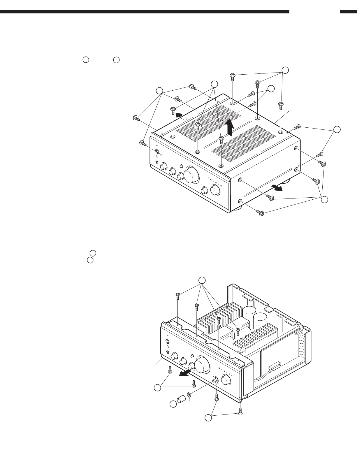
Top Cover
Remove 14 screws 1, 4 screws 2 and detach the Top Cover
in the arrow direction.
PMA-2000IVR
1
1
Front Panel
1. Remove 8 screws 3.
2. Pull out the knob 4 and remove the nut, then detach the
panel in the arrow direction.
1
2
Top Cover
2
1
Front Panel
3
3
4
Nut
3
3
PMA-2000IVR
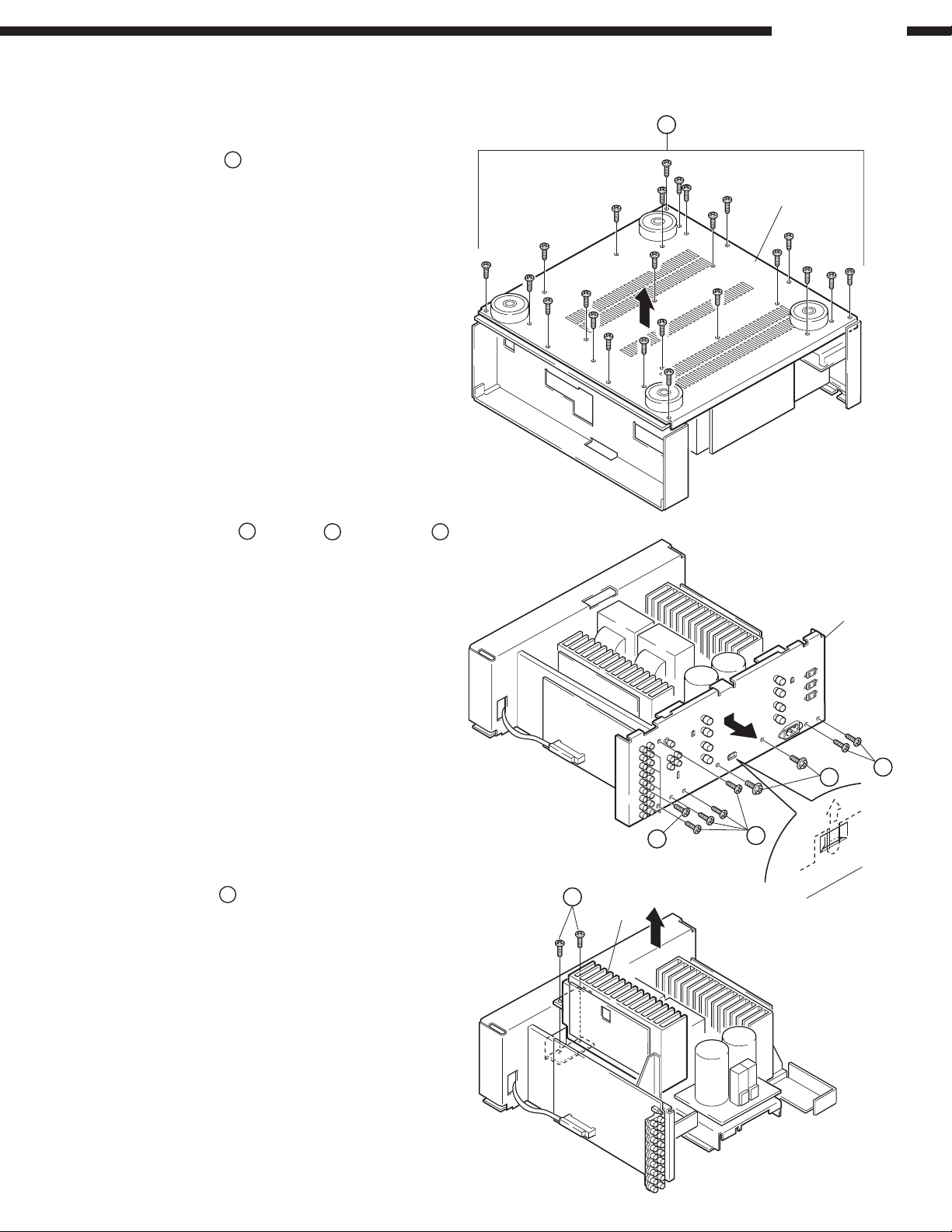
Bottom Plate
Remove 24 screws 5 and detach it in the arrow direction.
Rear Panel
1. Remove 5 screws 6, 6 screws 7 and 2 screws 8.
2. Detach the Rear Panel in the arrow direction.
5
Bottom Plate
Heat Sink Ass'y
Remove 2 screws 9 and detach the Heat Sink Ass'y in the
arrrow direction.
9
Heat Sink
Ass'y
Rear Panel
8
6
7
7
4
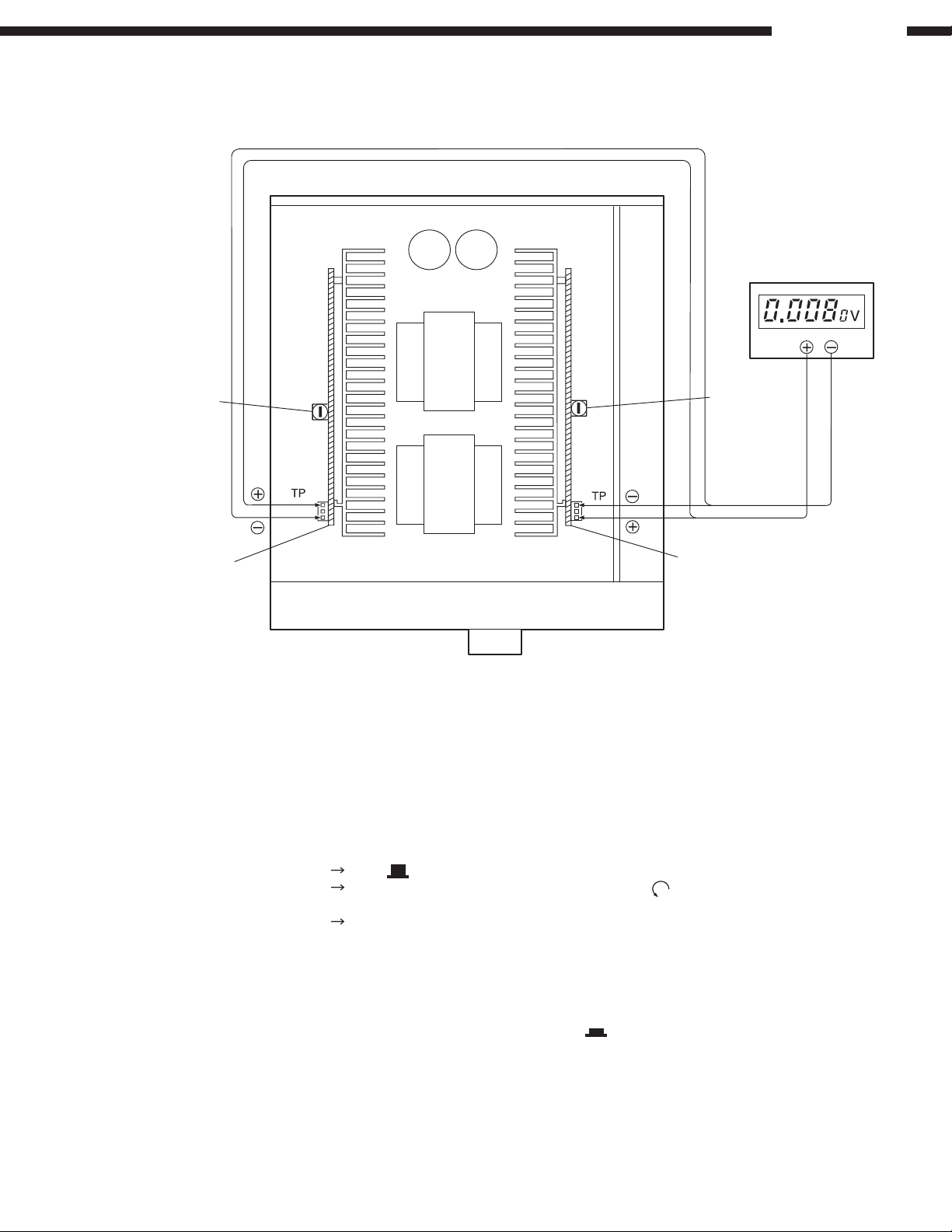
METHOD OF ADJUSTMENTS
DC Voltmeter
Main Volume
1U-3432-2
Power Amp P.W.B. (R)
VR502
1U-3432-1
Power Amp P.W.B. (L)
VR501
Power
Trans
Power
Trans
PMA-2000IVR
IDLING CURRENT
Setup
Adjustment
1. Lay the unit at an ordinary position away from a direct current from an air condition or fan. Do the adjustment at a
temperature between 15°C (59°F) and 30°C (86°F).
2. Set control as follows.
POWER SWITCH
VOLUME CONTROL Fully counterclockwise in the minimum position ( ).
SPEAKER Terminals
1. Remove top cover. And then connect DC Voltmeter to test points of 1U-3432-1 (Lch) and 1U-3432-2 (Rch) Power Amp
Printing Wiring Board.
2. Connect power cord to AC wall outlet, and turn POWER switch "ON" (
VR502 (Rch) clockwise so that the DC Voltmeter reads 12 ±0.5mV.
3. Then after 2 minutes warmup adjust VR501 and VR502 so that the DC Voltmeter reads 12 ±0.5mV.
4. And after 10 minutes warmup adjust VR501 and VR502 so that the DC Voltmeter reads 12 ±0.5mV.
OFF ( ).
(Main Volume and Semifixed resistors [VR501, 502])
Open: do not connect the speakers, dummy load etc.
). Within 10 seconds turn VR501 (Lch) and
5
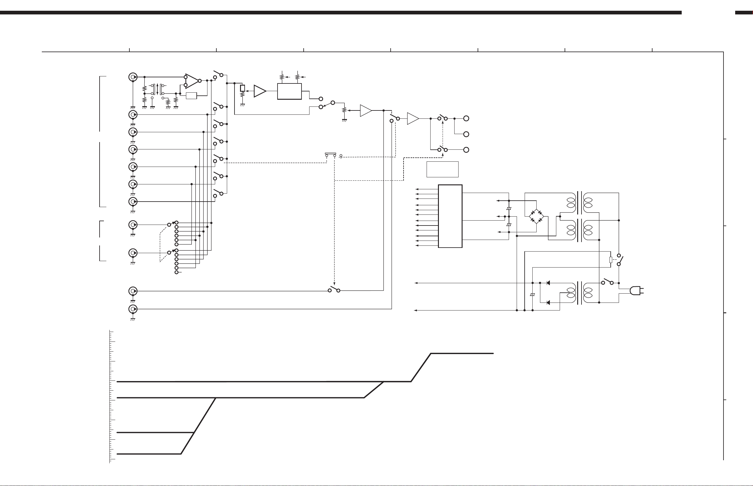
INPUT
REC OUT
PRE OUT
MAIN IN
P. AMP DIRECT 0.9V(-1dB)
CD etc.135mV(-17.4dB)
PHONO MM 2.2mV(-53dB)
PHONO MC 0.18mV(-75dB)
PHONO
CD
TUNER
DVD
/AUX-1
AUX-2
TAPE-1
/CD-R
TAPE-1
/CD-R
TAPE-2
/MD
TAPE-2
/MD
RIAA
MC
MM
47k 100
+
-
BASS
BUFFER
BALANCE
TREBLE
SOURCE
OFF
ON
DIRECT
MAIN VOLUME
POWER AMP DIRECT
FLAT AMP
TONE
POWER AMP
PROTECTOR
SPEAKER A
(MAIN)
SPEAKER B
(BI WIRING)
HEAD PHONE
POWER AMP
POWER AMP
POWER GND
VOLTAGE
REGULATOR
REC OUT SELECTOR
OFF ON
EQUALIZER
TONE AMP
POWER AMP
FLAT AMP
PROTECTOR
&
RELAY
+16V
-16V
GND
+16V
-16V
GND
+16V
-16V
GND
GND
+30V
+12V
-30V
GND
+
+
+
AC PLUG
80W/8ohm 25.3V(28dB)
40dB
-40dB
-50dB
-60dB
-70dB
-80dB
20dB
-20dB
10dB
-10dB
0dB
30dB
-30dB
(dBV)
BLOCK/LEVEL DIAGRAM
PMA-2000IVR
1 5678
32
4
A
B
C
D
E
6

PMA-2000IVR
21 22
(VASS)V
SS
VAREF
20 23
XOUT P60(AIN0)
19 24
XIN P61(AIN1)
18 25
RESET P62(AIN2)
17 26
TEST P63(AIN3)
16 27
P00 P64(AIN4)
15 28
P01 P65(AIN5)
14 29
P02 P66(AIN6)
13 30
P03 P67(AIN7)
12 31
P04 P10(INT0)
11 32
P05 P11(INT1)
10 33
P06 P12(INT2/TC1)
934
P07 P13(DVO)
835
(INT3/TC3)P70 P14(PPG)
736
(INT4)P71 P15(TC2)
637
(PDO/PWM)P72 P16
538
(SCK)P73 P17
439
(SI)P74 P20(INTS/STOP)
340
(SO)P75 P21(XIN)
241
(HSCK)P76 P22(XOUT)
142
(HSO)P77 V
DD
Power Supply
Terminal
Reset
I/O Terminal
Test Terminal
V
DD
V
SS
RESET
TEST
High Freq.
Oscillator
Connection
Terminal
XIN
P22
P20
I/O Port
VAREF
ALU
PSW Stack Pointer
Interrupt Control Circuit
Program Counter
Program Memory
(ROM)
Data memory
(RAM)
Unviersal register Blank
Flag RBS
System Control Circuit
Standby Control Circuit
Timing Generator
Time Base
Timer
16 bit
Timer/Counter
TC1
P2
8 bit
A/D Converter
P6 P0 P1 P7
TC2
8 bit
Timer/Counter
TC3 TC4
8 bit Serial
Interface
Command
register
Command
decoder
SIO HSO
Watch Dog
Timer
Clock
Generator
High Freq.
Use
Low Freq.
Use
Analog
Vref
XOUT
~
P67
P66
(Analog Input)
I/O Port
~
P07
P00
~
P17
P10
~
P77
P70
~
P65 (AIN5)
P60 (AIN0)
~
SEMICONDUCTORS
IC’s
TMP87CC46N-4C08 (IC901)
TMP87CC46N-4C08 (IC901) Terminal Function
Pin
No.
1 P77 O C AC POWER RELAY DRIVE
2 P76 O C
3 P75 (SO) O C
4 P74 (SI) O C
5 P73 (SCK) O C
6 P72 O C MUTE/STAND-BY LED DRIVE
7 P71 (INT4) O C MOTOR VOLUME UP
8 P70 (INT3) I C REMOTE CONTROL SIGNAL INPUT
9 P07 O C TAPE-2 LED, ARELAY DRIVE
10 P06 O C TAPE-1 LED, ARELAY DRIVE
11 P05 O C
12 P04 O C AUX-2 LED, ARELAY DRIVE
13 P03 O C DVD/AUX-1 LED, ARELAY DRIVE
14 P02 O C TUNER LED, ARELAY DRIVE
15 P01 O C CD LED, ARELAY DRIVE
16 P00 O C PHONE LED, ARELAY DRIVE
17 TEST to VSS
18 RESET RESET
19 XIN X’tal
20 XOUT X’tal
21 Vss (VAss) GND
22 VAREF to VDD
23 P60 I C MODEL SETTING INPUT
24 P61 I C
25 P62 I C
26 P63 I C FUNCTION SELECTOR SW INPUT
27 P64 I C
28 P65 O C MUTING SIGNAL INPUT
29 P66 O C
30 P67 O C
31 P10 (INT0) I C PROTECTOR INPUT
32 P11 (INT1) I C POWER OFF
33 P12 (INT2) O C MOTOR VOLUME DOWN
34 P13 O C
35 P14 O C
36 P15 O C
37 P16 O C
38 P17 O C
39 P20 STOP O C STOP MODE CANCEL
40 P21 O C
41 P22 O C
42 VDD +5V
NOTE: Pin No. : Terminal number of microcomputer.
Port Name
Type
Port Name : The name entered on the data sheet of microcomputer.
I/O : Input or output of port.
"I" = Input port
"O" = Output port
Type : Composition of port in case of output port.
"C" = CMOS output
Function : Function and logical level explanation of signals to be interface.
FunctionI/O
7
PMA-2000IVR
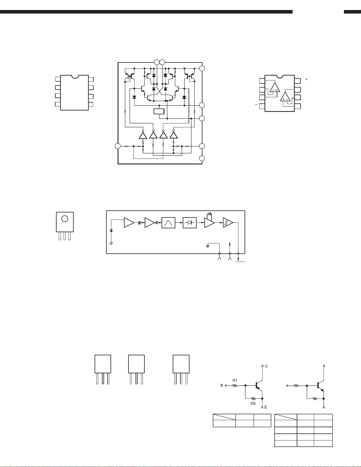
LB1639 (IC902)
TOP VIEW
V
V
IN1
1
2
GND
3
CONT
V
4
V
IN2
OTHERS
OUT1
8
V
CC
7
N.C.
6
5
OUT2
V
V
IN1
1
GP1U27X (Remote Control Sensor)
(IC103)
TOP VIEW
BA4558 (IC701)
V
OUT1
V
OUT2
5
8
REF
V
CC
V
7
V
CONT
3
GND
2
V
IN2
4
N.C.
6
NJM2082D (IC201)
A OUTPUT
A –INPUT
A+INPUT
1
1
2
3
V
4
V
8
B OUTPUT
7
2
6
B –INPUT
B +INPUT
5
Vcc
Vout
GND
TRANSISTORS
2SA933S (S)
2SA988 (E/F)
2SA1145 (O/Y)
2SA1546 (M/L)
2SB1328 (P)
2SC1740S (S)
2SC1841 (E/F)
2SC2705 (Y)
2SC3421 (O/Y)
2SC4001 (M/L)
2SD2004 (P)
FRONT
VIEW
C
E
2SA1837 (Y)
2SC4793 (Y)
B
Head
Amp
FRONT
VIEW
BCE
Limiter
Amp
Detector &
BPF
Comparator
DTA114ES
DTC114ES
DTC143ES
DTC143ZS
DTC144WS
FRONT
VIEW
C
B
E
Integrator
GND
DTA114ES
Hysteresis
Comparator
Vcc
PNP Type
Vout
DTC114ES
DTC143ES
DTC143ZS
DTC144WS
NPN Type
C
R1
B
DTA114ES
R1
10kohm
R2
10kohm
DTC114ES
DTC143ES
DTC143ZS
DTC144WS
R2
R1
10kohm
4.7kohm
4.7kohm 47kohm
47kohm
R2
10kohm
4.7kohm
22kohm
E
8
PMA-2000IVR
11EQS06
31DQ06
1SS270A
HZS2B-1
HZS3B-2
HZS5C-1
HZS9B-1
HZS11A-1
HZS12A-1
HZS30-1
MTZJ3.3A
MTZJ7.5A
MTZJ7.5C
MTZJ18A
SLR-56VC (Red)
TOP VIEW
2SJ78
2SK215
FRONT
VIEW
GSD
2SK373 (Y)
FRONT
VIEW
SGD
2SK184C (GR/BL)
2SK369 (BL/GR)-C
FRONT
VIEW
DGS
2SK2967
FRONT
VIEW
GDS
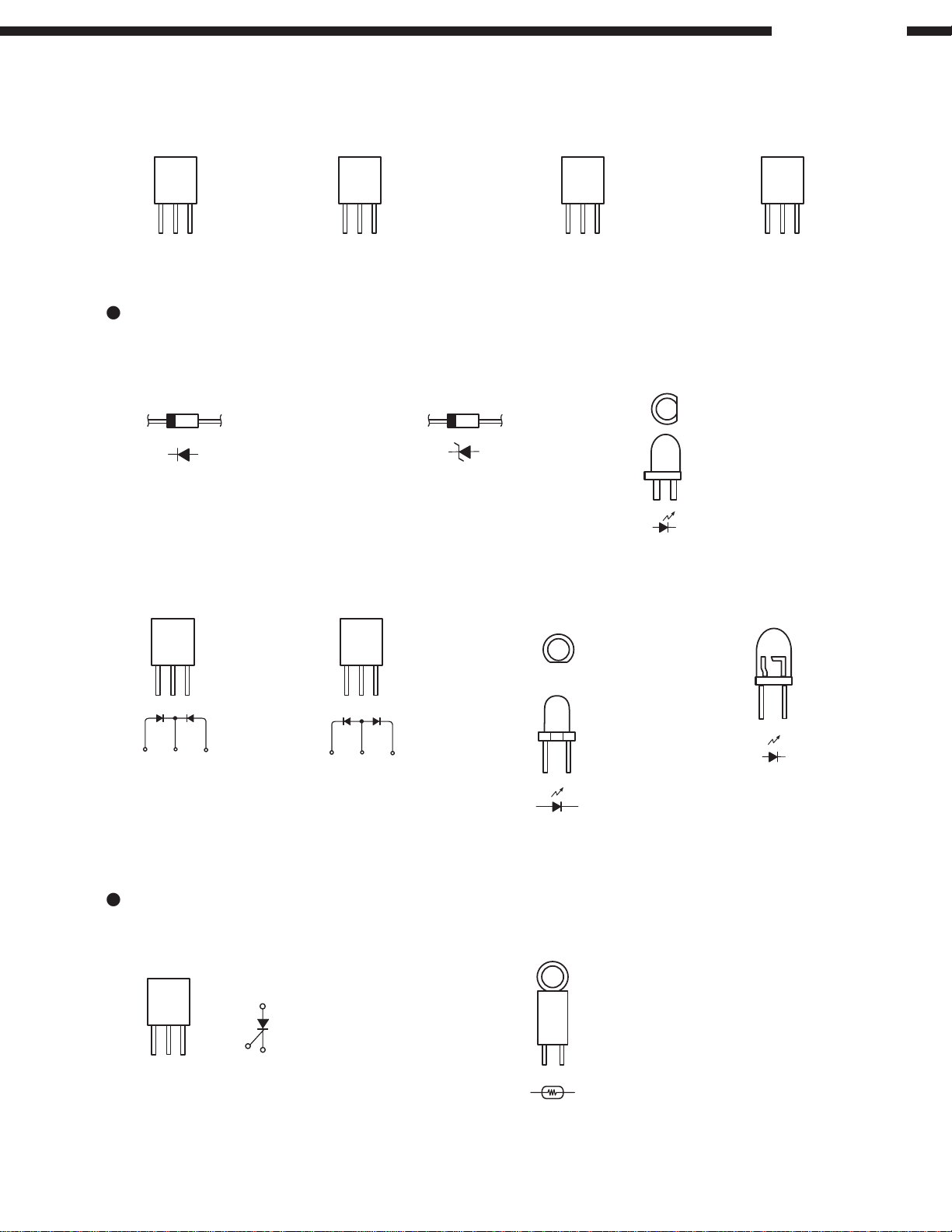
DIODES (LED included)
FCH20A15
FRONT
VIEW
AKA
FRH20A15
FRONT
VIEW
KAK
SF0R3G42
A
G
K
PTH9M04BD222TS2F333
FRONT
VIEW
GAK
SEL2E10C (Blue)
TOP VIEW
SIDE VIEW
SLR-342MG (Green)
THYRISTOR
THERMISTOR
9
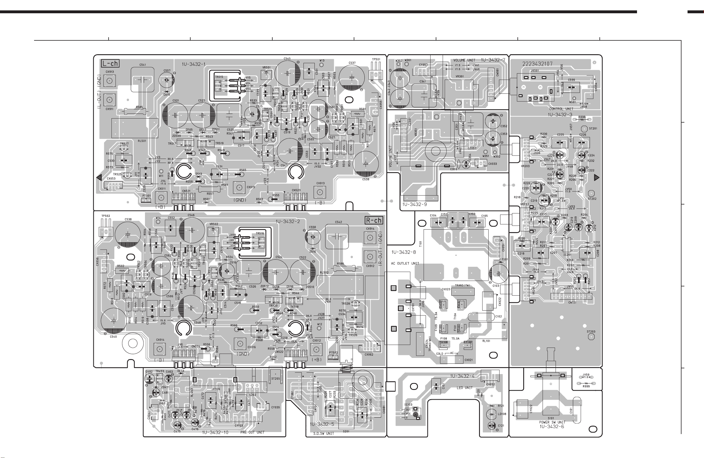
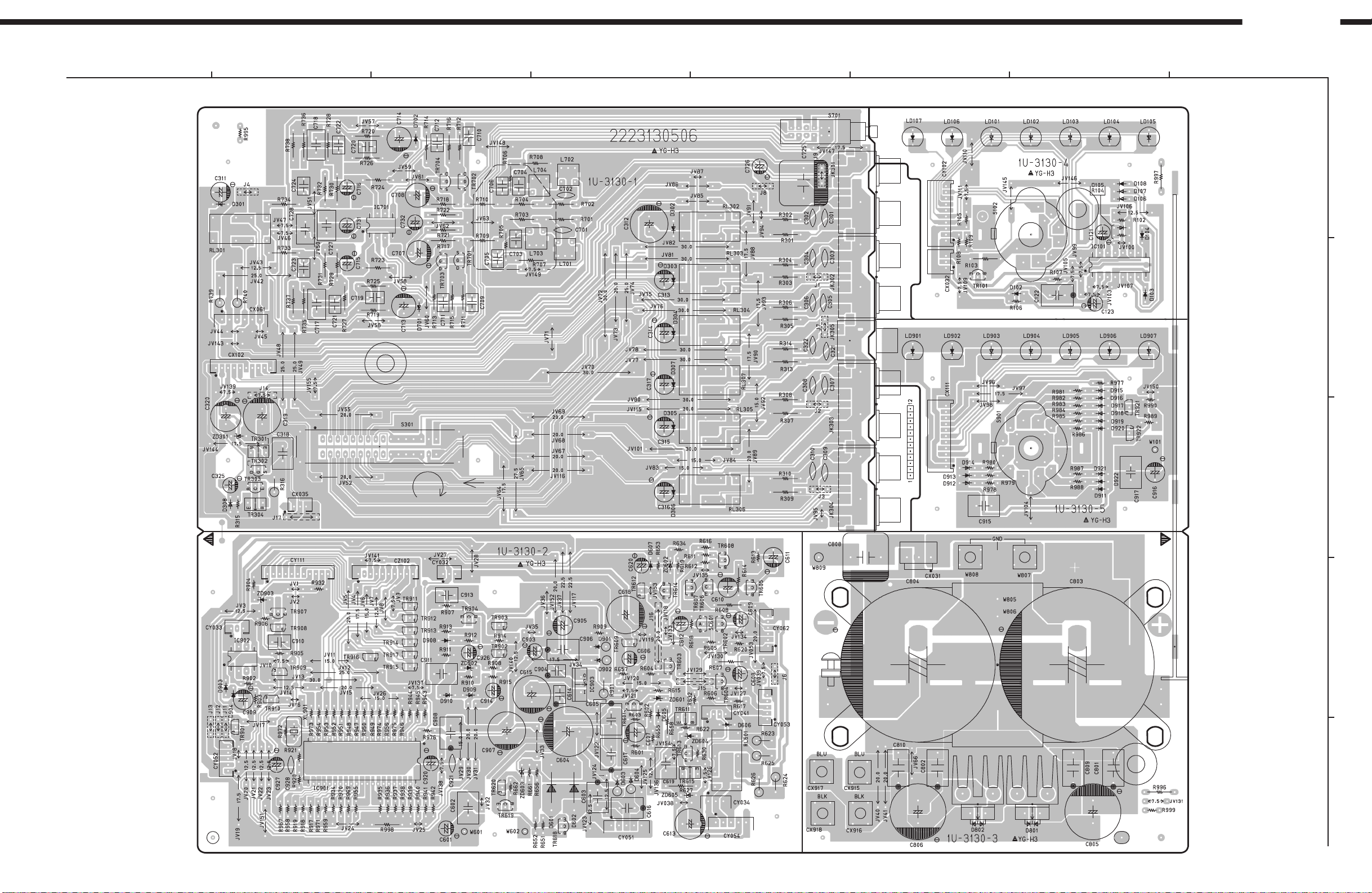
PRINTED WIRING BOARDS
PMA-2000IVR
1
2
1U-3432 POWER AMP P.W.B. UNIT Ass'y
1 5
3
4
5
1
5
76
15
8
A
15
18
1 5
1 3
1 8
B
8
15
15
12
1
4
5
110
C
D
16
1
16
18
1 5
14
13
110
10
1 2
COMPONENT SIDE
E
10
PMA-2000IVR
1
1U-3130 INPUT P.W.B. UNIT Ass'y
1
1
6
10
2
3
4
5
76
8
A
10
5
8
1
4
11 3
16
1
9
8
B
1 3
1
5
1
1 11
C
1 3
13
1 101 11
58
4
21
22
1 3
6
1
5
1
4
1
42
13
1
D
E
1
5
1
5
COMPONENT SIDE
11
 Loading...