


INTEGRATED STEREO AMPLIFIER
PMA-2000IVR
OPERATING INSTRUCTIONS
B

MUTE/STANDBY |
VOLUME |
|
|
|
INPUT SELECTOR |
||
|
TAPE-2/MD TAPE-1/CD-R PHONO |
CD |
TUNER DVD/AUX-1 AUX-2/P. DIRECT |
POWER |
SOURCE DIRECT |
|
|
¢ ON/STANDBY £OFF |
|
|
|
¢ ON
£OFF
REMOTE SENSOR
BASS |
TREBLE |
BALANCE |
REC OUT SELECTOR |
|
AMP |
|
|
|
|
|
|
CD |
POWER |
|
MUTING |
|
|
|
PHONO |
TUNER |
|
||
PHONES |
|
|
TAPE-112 |
AUX-1 |
|
|
|
|
|
|
9 |
|
|
||
|
|
|
COPY |
AUX-2 |
|
|
|
|
|
|
|
|
8 |
|
|
|
|
|
|
|
TRACK |
FUNCTION |
VOLUME |
|
|
LEFT |
RIGHT |
|
|
|
|
|
|
|
|
|
3 |
2 |
1 |
|
|
|
|
|
PAUSE |
STOP |
PLAY |
|
|
|
|
|
|
CD |
|
B
REMOTE CONTROL UNIT
RC-858
“SERIAL NO.
PLEASE RECORD UNIT SERIAL NUMBER ATTACHED TO THE REAR OF THE CABINET FOR FUTURE REFERENCE”
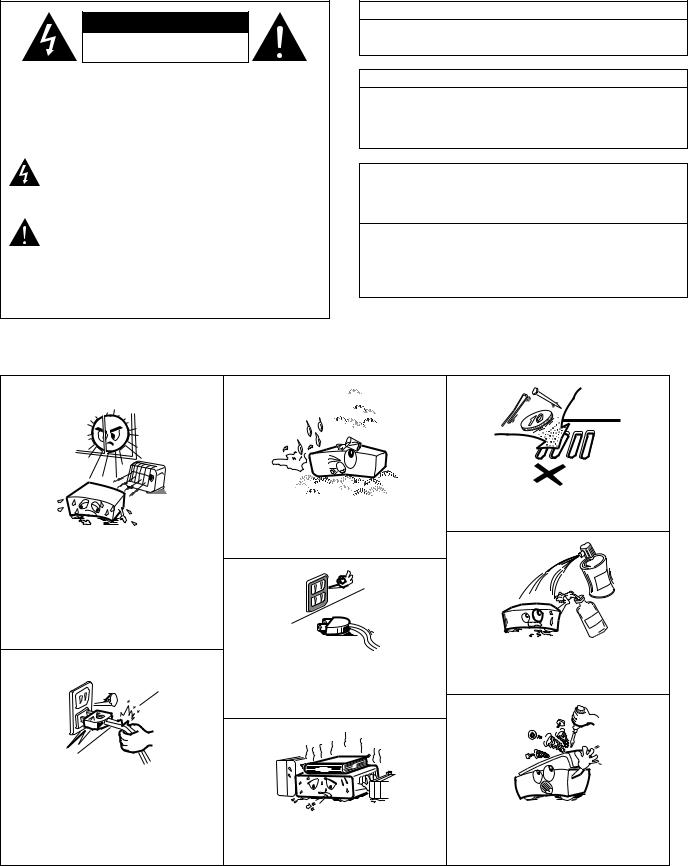
2 SAFETY PRECAUTIONS
CAUTION
RISK OF ELECTRIC SHOCK
DO NOT OPEN
CAUTION: TO REDUCE THE RISK OF ELECTRIC SHOCK, DO NOT REMOVE COVER (OR BACK). NO USER-SERVICEABLE PARTS INSIDE. REFER SERVICING TO QUALIFIED SERVICE PERSONNEL.
The lightning flash with arrowhead symbol, within an equilateral triangle, is intended to alert the user to the presence of uninsulated “dangerous voltage” within the product’s enclosure that may be of sufficient magnitude to constitute a risk of electric shock to persons.
The exclamation point within an equilateral triangle is intended to alert the user to the presence of important operating and maintenance (servicing) instructions in the literature accompanying the appliance.
WARNING: TO REDUCE THE RISK OF FIRE OR ELECTRIC SHOCK, DO NOT EXPOSE THIS APPLIANCE TO RAIN OR MOISTURE.
CAUTION
TO PREVENT ELECTRIC SHOCK, MATCH WIDE BLADE OF PLUG TO WIDE SLOT, FULLY INSERT.
ATTENTION
POUR ÉVITER LES CHOCS ÉLECTRIQUES, INTERODUIRE LA LAME LA PLUS LARGE DE LA FICHE DANS LA BORNE CORRESPONDANTE DE LA PRISE ET POUSSER JUSQU’ AU FOND.
This device complies with Part 15 of the FCC Rules. Operation is subject to the following two conditions: (1) This device may not cause harmful interference, and (2) this device must accept any interference received, including interference that may cause undesired operation.
This Class B digital apparatus meets all requirements of the Canadian Interference-Causing Equipment Regulations.
Cet appareil numérique de la classe B respecte toutes les exigences du Règlement sur le matériel brouilleur du Canada.
2 NOTE ON USE
• Keep the set free from moisture, water, and dust.
•Avoid high temperatures.
Allow for sufficient heat dispersion when
installed on a rack.
• Unplug the power cord when not using the set for long periods of time.
• Do not let foreign objects in the set.
•Do not let insecticides, benzene, and thinner come in contact with the set.
• Handle the power cord carefully.
Hold the plug when unplugging the cord.
* (For sets with ventilation holes)
• Do not obstruct the ventilation holes.
•Never disassemble or modify the set in any way.
2
SAFETY INSTRUCTIONS
1.Read Instructions – All the safety and operating instructions should be read before the product is operated.
2.Retain Instructions – The safety and operating instructions should be retained for future reference.
3.Heed Warnings – All warnings on the product and in the operating instructions should be adhered to.
4.Follow Instructions – All operating and use instructions should be followed.
5.Cleaning – Unplug this product from the wall outlet before cleaning. Do not use liquid cleaners or aerosol cleaners.
6.Attachments – Do not use attachments not recommended by the product manufacturer as they may cause hazards.
7.Water and Moisture – Do not use this product near water – for example, near a bath tub, wash bowl, kitchen sink, or laundry tub; in a wet basement; or near a swimming pool; and the like.
8.Accessories – Do not place this product on an unstable cart, stand, tripod, bracket, or table. The product may fall, causing serious injury to a child or adult, and serious damage to the product. Use only with a cart, stand, tripod, bracket, or table recommended by the manufacturer, or sold with the product. Any mounting of the product should follow the manufacturer’s instructions, and should use a
mounting accessory recommended by the
manufacturer.
9. A product and cart combination should be moved with care. Quick stops, excessive force, and uneven surfaces may cause the product and cart combination to overturn.
10.Ventilation – Slots and openings in the cabinet are provided for ventilation and to ensure reliable operation of the product and to protect it from overheating, and these openings must not be blocked or covered. The openings should never be blocked by placing the product on a bed, sofa, rug, or other similar surface. This product should not be placed in a built-in installation such as a bookcase or rack unless proper ventilation is provided or the manufacturer’s instructions have been adhered to.
11.Power Sources – This product should be operated only from the type of power source indicated on the marking label. If you are not sure of the type of power supply to your home, consult your product dealer or local power company. For products intended to operate from battery power, or other sources, refer to the operating instructions.
12.Grounding or Polarization – This product may be equipped with a polarized alternating-current line plug (a plug having one blade wider than the other). This plug will fit into the power outlet only one way. This is a safety feature. If you are unable to insert the plug fully into the outlet, try reversing the plug. If the plug should still fail to fit, contact your electrician to replace your obsolete outlet. Do not defeat the safety purpose of the
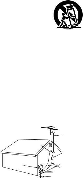
FIGURE A
EXAMPLE OF ANTENNA GROUNDING
AS PER NATIONAL
ELECTRICAL CODE ANTENNA
LEAD IN
WIRE
GROUND
CLAMP
ANTENNA DISCHARGE UNIT
(NEC SECTION 810-20)
ELECTRIC
SERVICE
EQUIPMENT
GROUNDING CONDUCTORS (NEC SECTION 810-21)
GROUND CLAMPS
POWER SERVICE GROUNDING ELECTRODE SYSTEM
(NEC ART 250, PART H)
NEC - NATIONAL ELECTRICAL CODE
13.Power-Cord Protection – Power-supply cords should be routed so that they are not likely to be walked on or pinched by items placed upon or against them, paying particular attention to cords at plugs, convenience receptacles, and the point where they exit from the product.
15.Outdoor Antenna Grounding – If an outside antenna or cable system is connected to the product, be sure the antenna or cable system is grounded so as to provide some protection against voltage surges and built-up static charges. Article 810 of the National Electrical Code, ANSI/NFPA 70, provides information with regard to proper grounding of the mast and supporting structure, grounding of the lead-in wire to an antenna discharge unit, size of grounding conductors, location of antenna-discharge unit, connection to grounding electrodes, and requirements for the grounding electrode. See Figure A.
16.Lightning – For added protection for this product during a lightning storm, or when it is left unattended and unused for long periods of time, unplug it from the wall outlet and disconnect the antenna or cable system. This will prevent damage to the product due to lightning and power-line surges.
17.Power Lines – An outside antenna system should not be located in the vicinity of overhead power lines or other electric light or power circuits, or where it can fall into such power lines or circuits. When installing an outside antenna system, extreme care should be taken to keep from touching such power lines or circuits as contact with them might be fatal.
18.Overloading – Do not overload wall outlets, extension cords, or integral convenience receptacles as this can result in a risk of fire or electric shock.
19.Object and Liquid Entry – Never push objects of any kind into this product through openings as they may touch dangerous voltage points or short-out parts that could result in a fire or electric shock. Never spill liquid of any kind on the product.
20.Servicing – Do not attempt to service this product yourself as opening or removing covers may expose you to dangerous voltage or other hazards. Refer all servicing to qualified service personnel.
21.Damage Requiring Service – Unplug this product from the wall outlet and refer servicing to qualified service personnel under the following conditions:
a)When the power-supply cord or plug is damaged,
b)If liquid has been spilled, or objects have fallen into the product,
c)If the product has been exposed to rain or water,
d)If the product does not operate normally by following the operating instructions. Adjust only those controls that are covered by the operating instructions as an improper adjustment of other controls may result in damage and will often require extensive work by a qualified technician to restore the product to its normal operation,
e)If the product has been dropped or damaged in any way, and
f)When the product exhibits a distinct change in performance
– this indicates a need for service.
22.Replacement Parts – When replacement parts are required, be sure the service technician has used replacement parts specified by the manufacturer or have the same characteristics as the original part. Unauthorized substitutions may result in fire, electric shock, or other hazards.
23.Safety Check – Upon completion of any service or repairs to this product, ask the service technician to perform safety checks to determine that the product is in proper operating condition.
24.Wall or Ceiling Mounting – The product should be mounted to a wall or ceiling only as recommended by the manufacturer.
25.Heat – The product should be situated away from heat sources such as radiators, heat registers, stoves, or other products (including amplifiers) that produce heat.
3
NOTE:
1.Always keep the POWER switch on the main unit turned on.
2.Turn the power on and off from the remote control unit.
3.Unplug the power cord when you do not plan to use the unit for a long period of time.
CAUTION:
If only the MUTE/STANDBY LED is lit red, this means that the power is turned off from the remote control unit. Turn the power on from the remote control unit.
— TABLE OF CONTENTS —
zDESIGNATIONS AND
FUNCTIONS OF PANEL CONTROLS …………………………4 ~ 7
x CONNECTIONS …………………………………………………7, 8 c OPERATION …………………………………………………………9
v REMOTE CONTROL OPERATION ……………………………10, 11 b TROUBLESHOOTING ………………………………………………12
n SPECIFICATIONS ……………………………………………………13
Please check to make sure the following items are included with the main unit in the carton:
(1)Operating Instructions ………………………………………………1
(2)Warranty ………………………………………………………………1
(3)Remote Control Unit (RC-858) ………………………………………1
(4)Batteries R03 (AAA) …………………………………………………2
(5)Power Supply Cord ……………………………………………………1
(6)Service Station List ……………………………………………………1
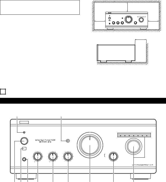
PRECAUTIONS FOR INSTALLATION
For heat dispersal, leave at least 10 cm of space between the top, back and sides of this unit and the wall or other components.
|
10cm or more |
|
|
|
B |
|
|
Wall
1 DESIGNATIONS AND FUNCTIONS OF PANEL CONTROLS
Front Panel
!1 |
!0 |
|
|
B |
|
|
|
MUTE/STANDBY |
VOLUME |
|
|
|
|
|
|
|
INPUT SELECTOR |
||
|
TAPE-2/MD TAPE-1/CD-R PHONO |
CD |
TUNER DVD/AUX-1 AUX-2/P. DIRECT |
POWER |
SOURCE DIRECT |
|
|
¢ ON/STANDBY £OFF |
|
|
|
¢ON
£OFF
REMOTE SENSOR
BASS |
TREBLE |
BALANCE |
REC OUT SELECTOR |
|
|
|
|
|
CD |
|
|
|
PHONO |
TUNER |
PHONES |
|
|
TAPE-112 |
AUX-1 |
|
|
|
||
|
|
|
COPY |
AUX-2 |
|
|
LEFT |
RIGHT |
|
q w e r t y |
u |
i |
o |
4

q Power switch (POWER)
When the power switch is turned ON (¢), the MUTE/STANDBY LED !1lights.
When the power switch is turned ON, power is supplied to the unit. It takes a few seconds after the power is turned on for the unit to warm up. This is due to the built-in muting circuit that eliminates noise during the on/off operation.
w Remote Control Sensor
(REMOTE SENSOR)
This sensor receives the infra-red light transmitted from the wireless remote control unit.
For remote control, point the wireless remote control unit towards the sensor.
e Headphone jack (PHONES)
This jack is used to plug in the headphones.
(The SPEAKER output is turned off when the headphones are plugged in.)
To prevent hearing loss, do not raise the volume level excessively when using headphones.
r Bass control (BASS)
This knob is used to control the bass quality of the sound. When the knob is set at the center position, the frequency characteristics are flattened in the range below 1000 Hz. The bass is emphasized as the knob is moved off center to the right (,), and reduced as it is moved to the left (.).
t Treble control (TREBLE)
This knob is used to control the treble quality of the sound. When the knob is set at the center position, the frequency characteristics are flattened in the range above 1000 Hz. The treble is emphasized as the knob is moved off center to the right (,), and reduced as it is moved to the left (.).
y Balance control (BALANCE)
This knob is used to adjust the balance between the left and right channels.
When it is set to the center position, the amplitude of the amplifier is equal on both sides. If the volume on the right side is too low, turn the knob to the right (,). If the volume on the left side is too low, turn the knob to the left (.). This will achieve an even balance on the left and right sides.
u Volume control (VOLUME)
This knob controls the overall volume level.
Turn the knob to the right (,) to raise the volume and to the left (.) to lower it.
i Recording output selector (REC OUT SELECTOR)
Use this to select the output source for recording onto a tape deck, etc.
•TAPE-1 12:
(COPY)
Use this position when making copies of tapes using two tape decks. The input signal from the deck connected to the TAPE-1/CD-R input terminals is fed to the TAPE-2/MD REC OUT terminals.
•PHONO:
Used to recording from the turntable.
•CD:
Used to recording from the CD player.
•TUNER:
Used to recording from the tuner.
•AUX-1:
Used to recording component that connected to the DVD/ AUX-1 terminals.
•AUX-2:
Used to recording component that connected to the AUX- 2 terminals.
NOTE:
Copying is not possible from TAPE-2/MD to TAPE- 1/CD-R.
o Input selector switch (INPUT SELECTOR)
Use these to select the program source.
When the switch for the desired program source is selected, its LED lights. One program source only can be selected at a time, as follows.
•TAPE-2/MD:
Use this position when using the tape deck, etc., connected to the TAPE-2/MD terminals.
•TAPE-1/CD-R:
Use this position when using the tape deck, etc., connected to the TAPE-1/CD-R terminals.
•PHONO:
Use this position when using the record player connected
to the PHONO terminals.
Use the CARTRIDGE selection switch @1to switch the sensitivity to correspond to the cartridge type being used.
•CD:
Used to listen a compact disc player or other component that is connected to the CD terminals.
•TUNER:
Used to play a component such as an FM/AM tuner or a TV tuner that is connected to the TUNER terminals.
•DVD/AUX-1:
Used to play a component such as a HiFi video player, TV tuner or tape deck that is connected to the DVD/AUX-1 terminals.
•AUX-2/P. DIRECT:
Used to play a component such as a HiFi video player, TV tuner or tape deck that is connected to the AUX-2 terminals. And power amp direct terminal is selected by using the P. DIRECT switch on the back panel.
NOTE:
When selecting the power amp direct terminal, volume control function of this unit does not work, so set volume level by the component connecting to this terminal.
!0Source direct switch (SOURCE DIRECT)
The controls (BASS r, TREBLE t and BALANCE y) can be used when this switch is in the OFF (£) position.
When set to the ON (¢) position, the above controls are by passed and the signals are input directly to the volume control circuit, providing high quality sound.
!1Mute/Standby LED (MUTE/STANDBY)
This LED flashes while the muting circuit is activated when the power is turned on and when muting is turned on from the remote control unit, and remains lit (without flashing) while the power switch q is turned ON (¢).
5
 Loading...