


DVD SURROUND SYSTEM
D-M51DVS
DVD SURROUND RECEIVER
ADV-M51
OPERATING INSTRUCTIONS BEDIENUNGSANLEITUNG
MODE D’EMPLOI
Radio |
MP |
WMA |
OFF |
|
ON |
|
|
|
VCR |
|
|
|
SLEEP |
REC |
TITLE |
TIME |
|
NTSC/PAL |
||||
SOURCE |
|
TV IN |
T |
V |
CLEAR |
ENTER |
CHARAC. |
EDIT/MENU |
|
A-B REPEAT |
SLIDE MODE |
ZOOM |
||
|
|
TV CH - |
TV CH + |
|
RDS |
PTY |
CT |
CD SRS |
RT |
PROG/DIRECT |
REPEAT |
RANDOM |
SEARCH MODE |
|
MODE |
MEMO |
BAND |
|
|
|
|
|
TUNING / |
|
DVD |
TUNER |
D.AUX |
TV VOL |
|
1 |
2 |
3 |
+ |
|
MD/LINE-1 |
TAPE /LINE-2 |
|
- |
|
4 |
5 |
6 |
||
|
5CH STEREO |
AUTO DECODE |
TUNER |
|
7 |
8 |
9 |
+ |
|
DIRECT |
STEREO |
VIRTUAL |
|
CH |
CALL |
0/10 |
+10 |
- |
|
|
SURROUND SELECT |
|
TEST TONE INPUT MODE |
SURROUND |
FUNCTION |
||
DVD SURROUND RECEIVER ADV-M51 |
PUSH-PARAM |
|
|
|
|
|
|
|
|
|
|
|
TUNER TV / VCR |
||
|
|
|
A / V |
|
DVD |
|
IN/SURR. |
|
|
|
|
SYSTEM |
MD |
|
IN/SURR. |
|
|
|
|
|
CDR |
TAPE |
|
|
|
|
1 |
|
2 |
|
+ |
|
MENU SET |
BAND |
DVD |
|
|
|
|
|
TONE SDB |
|
8 |
9 |
|
|
|
V I D E O |
VOLUME |
|
|
|
- |
||
|
|
|
|
||||
|
|
|
6 |
7 |
|
||
|
FUNCTION |
|
|
STATUS |
|
|
|
|
|
|
3 |
|
|
MUTING |
|
ON STANDBY |
|
|
SETUP |
|
|
|
TONE /SDB |
|
PHONES |
|
|
|
|
||
|
|
|
|
|
|
|
|
|
|
|
|
ENTER |
|
|
|
|
|
|
|
|
|
|
SURROUND |
|
|
|
CH SELECT |
|
|
|
PARAMETER |
|
|
|
|
|
- VCR CH + |
||
|
|
|
RETURN |
DISPLAY |
MENU |
|
TOP MENU |
|
|
|
ANGLE |
AUDIO |
SUB TITLE |
||
RC-966
FOR ENGLISH READERS PAGE 3 ~ PAGE 112
2We greatly appreciate your purchase of this unit.
2To be sure you take maximum advantage of all the features this unit has to offer, read these instructions carefully and use the set properly. Be sure to keep this manual for future reference should any questions or problems arise.
“SERIAL NO.
PLEASE RECORD UNIT SERIAL NUMBER ATTACHED TO THE REAR OF THE CABINET FOR FUTURE REFERENCE”
FÜR DEUTSCHE LESER SEITE 113 ~ SEITE 222
2Wir danken Ihnen dafür, dass Sie sich für den Kauf dieses Gerätes entschieden haben.
2Lesen Sie diese Anleitung sorgfältig durch, damit sichergestellt werden kann, dass Sie sämtliche Funktionen ausnutzen, die dieses Gerät zu bieten hat, und damit Sie das Gerät ordnungsgemäß verwenden. Stellen Sie sicher, dass Sie dieses Handbuch für ein zukünftiges Nachschlagen aufbewahren, falls Sie irgendwelche Fragen oder Probleme habe sollten.
“SERIEN-NR.
BITTE NOTIEREN SIE DIE SICH AUF DER RÜCKSEITE DES GERÄTES BEFINDLICHE SERIENNUMMER ZUR SPÄTEREN REFERENZNAHME”
POUR LES LECTEURS FRANCAIS PAGE 223 ~ PAGE 332
2Nous vous remercions pour l’achat de cet appareil.
2Pour être sûr de profiter au maximum de toutes les caractéristiques qu’offre cet appareil, lire avec soin ces instructions et bien utiliser l’appareil. Toujours conserver ce mode d’emploi pour s’y référer ultérieurement en cas de question ou de problème.
“NO. DE SERIE
PRIERE DE NOTER LE NUMERO DE SERIE DE L’APPAREIL INSCRIT A L’ARRIERE DU COFFRET DE FAÇON A POUVOIR LE CONSULTER EN CAS DE PROBLEME.”
ENGLISH DEUTSCH FRANCAIS
CAUTION
RISK OF ELECTRIC SHOCK
DO NOT OPEN
CAUTION: TO REDUCE THE RISK OF ELECTRIC SHOCK, DO NOT REMOVE COVER (OR BACK). NO USER SERVICEABLE PARTS INSIDE. REFER SERVICING TO QUALIFIED SERVICE PERSONNEL.
WARNING: TO PREVENT FIRE OR SHOCK HAZARD, DO NOT EXPOSE THIS APPLIANCE TO RAIN OR MOISTURE.
ATTENZIONE: QUESTO APPARECCHIO E’ DOTATO DI DISPOSITIVO OTTICO CON RAGGIO LASER.
L’USO IMPROPRIO DELL’APPARECCHIO PUO’ CAUSARE PERICOLOSE ESPOSIZIONI A RADIAZIONI!
The lightning flash with arrowhead symbol, within an equilateral triangle, is intended to alert the user to the presence of uninsulated “dangerous voltage” within the product’s enclosure that may be of sufficient magnitude to constitute a risk of electric shock to persons.
The exclamation point within an equilateral triangle is intended to alert the user to the presence of important operating and maintenance (servicing) instructions in the literature accompanying the appliance.
,,CLASS 1
LASER PRODUCT,,
•DECLARATION OF CONFORMITY
We declare under our sole responsibility that this product, to which this declaration relates, is in conformity with the following standards:
EN60065, EN55013, EN55020, EN61000-3-2 and EN61000-3-3.
Following the provisions of 73/23/EEC, 89/336/EEC and 93/68/EEC Directive.
•ÜBEREINSTIMMUNGSERKLÄRUNG
Wir erklären unter unserer Verantwortung, daß dieses Produkt, auf das sich diese Erklärung bezieht, den folgenden Standards entspricht:
EN60065, EN55013, EN55020, EN61000-3-2 und EN61000-3-3.
Entspricht den Verordnungen der Direktive 73/23/EEC, 89/336/EEC und 93/68/EEC.
•DECLARATION DE CONFORMITE
Nous déclarons sous notre seule responsabilité que l’appareil, auquel se réfère cette déclaration, est conforme aux standards suivants:
EN60065, EN55013, EN55020, EN61000-3-2 et EN61000-3-3.
D’après les dispositions de la Directive 73/23/EEC, 89/336/EEC et 93/68/EEC.
CLASS 1 LASER PRODUCT |
|
LUOKAN 1 LASERLAITE |
VARNINGOM APPARATEN ANVÄNDS PÅ ANNAT SÄTT ÄN I DENNA |
KLASS 1 LASERAPPARAT |
BRUKSANVISNING SPECIFICERATS, KAN ANVÄNDAREN |
ADVARSEL:USYNLIG LASERSTRÅLING VED ÅBNING, NÅR |
UTSÄTTAS FÖR OSYNLIG LASERSTRÅLNING SOM |
SIKKERHEDSAFBRYDERE ER UDE AF FUNKTION. |
ÖVERSKRIDER GRÄNSEN FÖR LASERKLASS 1. |
UNDGÅ UDSAETTELSE FOR STRÅLING. |
|
VAROITUS!LAITTEEN KÄYTTÄMINEN MUULLA KUIN TÄSSÄ |
|
KÄYTTÖOHJEESSA MAINITULLA TAVALLA SAATTAA |
|
ALTISTAA KÄYTTÄJÄN TURVALLISUUSLUOKAN 1 |
|
YLITTÄVÄLLE NÄKYMÄTTÖMÄLLE LASERSÄTEILYLLE. |
|
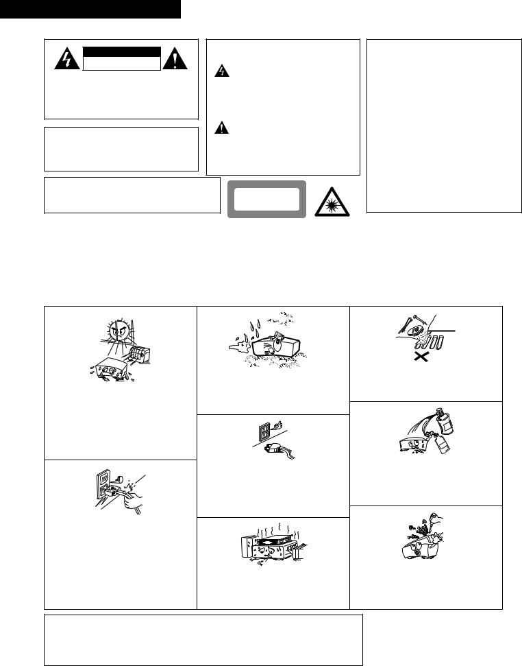
NOTE ON USE / HINWEISE ZUM GEBRAUCH /OBSERVATIONS RELATIVES A L’UTILISATION
•Avoid high temperatures.
Allow for sufficient heat dispersion when installed on a rack.
•Vermeiden Sie hohe Temperaturen. Beachten Sie, daß eine ausreichend Luftzirkulation gewährleistet wird, wenn das Gerät auf ein Regal gestellt wird.
•Eviter des températures élevées
Tenir compte d’une dispersion de chaleur suffisante lors de l’installation sur une étagère.
•Handle the power cord carefully.
Hold the plug when unplugging the cord.
•Gehen Sie vorsichtig mit dem Netzkabel um. Halten Sie das Kabel am Stecker, wenn Sie den Stecker herausziehen.
•Manipuler le cordon d’alimentation avec précaution.
Tenir la prise lors du débranchement du cordon.
•Keep the set free from moisture, water, and dust.
•Halten Sie das Gerät von Feuchtigkeit, Wasser und Staub fern.
•Protéger l’appareil contre l’humidité, l’eau et lapoussière.
•Unplug the power cord when not using the set for long periods of time.
•Wenn das Gerät eine längere Zeit nicht verwendet werden soll, trennen Sie das Netzkabel vom Netzstecker.
•Débrancher le cordon d’alimentation lorsque l’appareil n’est pas utilisé pendant de longues périodes.
• (For sets with ventilation holes)
Do not obstruct the ventilation holes.
•Die Belüftungsöffnungen dürfen nicht verdeckt werden.
•Ne pas obstruer les trous d’aération.
•Do not let foreign objects in the set.
•Keine fremden Gegenstände in das Gerät kommen lassen.
•Ne pas laisser des objets étrangers dans l’appareil.
•Do not let insecticides, benzene, and thinner come in contact with the set.
•Lassen Sie das Gerät nicht mit Insektiziden, Benzin oder Verdünnungsmitteln in Berührung kommen.
•Ne pas mettre en contact des insecticides, du benzène et un diluant avec l’appareil.
•Never disassemble or modify the set in any way.
•Versuchen Sie niemals das Gerät auseinander zu nehmen oder auf jegliche Art zu verändern.
•Ne jamais démonter ou modifier l’appareil d’une manière ou d’une autre.
CAUTION
•The ventilation should not be impeded by covering the ventilation openings with items, such as newspapers, table-cloths, curtains, etc.
•No naked flame sources, such as lighted candles, should be placed on the apparatus.
•Please be care the environmental aspects of battery disposal.
•The apparatus shall not be exposed to dripping or splashing for use.
•No objects filled with liquids, such as vases, shall be placed on the apparatus.
2
ENGLISH
2INTRODUCTION
Thank you for choosing the DENON ADV-M51 DVD Surround Receiver. This remarkable component has been engineered to provide superb surround sound listening with home theater sources such as DVD, as well as providing outstanding high fidelity reproduction of your favorite music sources. As this product is provided with an immense array of features, we recommend that before you begin hookup and operation that you review the contents of this manual before proceeding.
TABLE OF CONTENTS
z BEFORE USING .......................................................................................... |
4 |
⁄3DOLBY / DTS SURROUND................................................................. |
47~49 |
x CAUTIONS ON INSTALLATION .............................................................. |
4, 5 |
⁄4SURROUND PLAYBACK..................................................................... |
50~59 |
c CAUTIONS ON HANDLING ........................................................................ |
5 |
⁄5LISTENING TO THE RADIO................................................................ |
60~64 |
v FEATURES................................................................................................... |
5 |
⁄6ON-SCREEN DISPLAY .............................................................................. |
65 |
b DISCS.......................................................................................................... |
6 |
⁄7USING THE ON-SCREEN DISPLAY .................................................... |
66~83 |
n CAUTIONS ON HANDLING DISCS............................................................. |
7 |
⁄8USING THE TIMER ............................................................................. |
84~90 |
m CONNECTIONS .................................................................................... |
8~14 |
⁄9CHANGING THE DEFAULT SETTINGS (DVD)................................... |
91~103 |
, PART NAMES AND FUNCTIONS ....................................................... |
15~19 |
¤0SYSTEM FUNCTIONS .................................................................... |
104~108 |
. REMOTE CONTROL UNIT.................................................................. |
20~28 |
¤1LAST FUNCTION MEMORY ................................................................... |
109 |
⁄0SETTING UP THE SYSTEM ................................................................ |
29~38 |
¤2INITIALIZATION OF THE MICROPROCESSOR ...................................... |
109 |
⁄1PLAY BACK......................................................................................... |
39~44 |
¤3TROUBLESHOOTING ..................................................................... |
110, 111 |
⁄2OPERATING THE SURROUND FUNCTIONS...................................... |
44~46 |
¤4SPECIFICATIONS .................................................................................... |
112 |
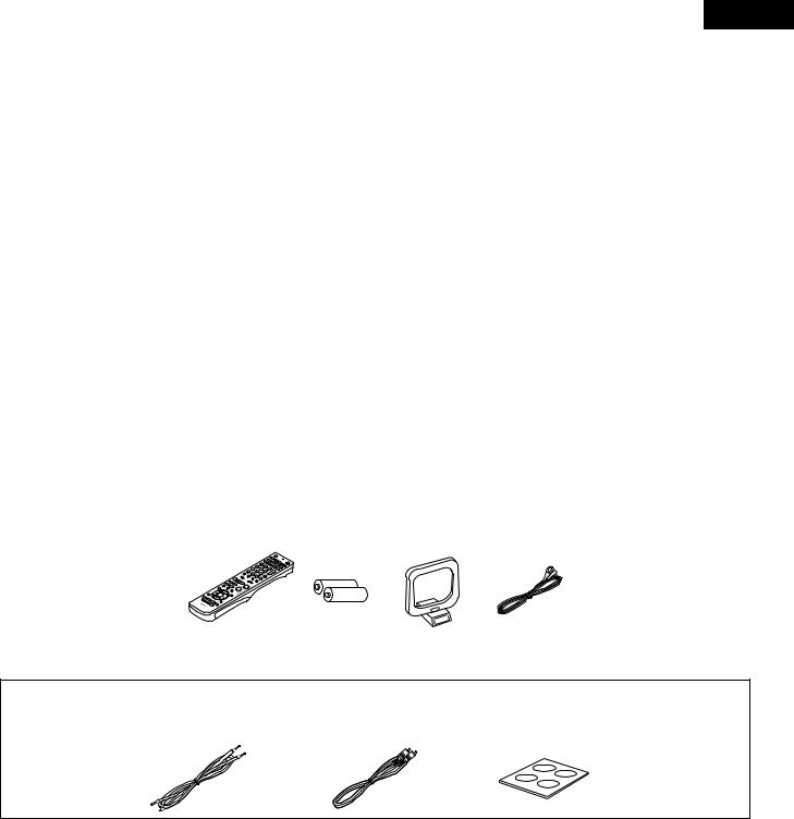
2ACCESSORIES
ADV-M51 |
Check that the following parts are included in addition to the main unit: |
|
||||||
q Operating instructions |
........................................1 |
w Service station list |
.............................................. |
1 |
e Remote control unit (RC-966) |
.............................1 |
||
r R6P/AA batteries ................................................ |
2 |
t AM loop antenna ................................................ |
|
1 |
y FM indoor antenna ............................................. |
1 |
||
|
e |
|
|
r |
t |
|
y |
|
|
|
|
|
|
|
|
|
|
|
|
|
|
|
|
|
|
|
SYS-M51 (D-M51DVS only)
q Cord A .................................................................................................... |
2 |
wCord B........................................................................................ |
1 |
(Used to connect the SC-A3L) |
|
(Used to connect the DSW-3L) |
|
(Length: Approx. 3 meters) |
|
(Length: Approx. 3 meters, RCA PIN) |
|
e Anti-Slip pad (4 pcs / 1 sheet) ................................................................ |
2 |
|
|
q |
w |
e |
|
3
ENGLISH
1 BEFORE USING
Pay attention to the following before using this unit:
•Moving the set
To prevent short circuits or damaged wires in the connection cords, always unplug the power cord and disconnect the connection cords between all other audio components when moving the set.
•Before turning the power switch on
Check once again that all connections are proper and that there are not problems with the connection cords. Always set the power switch to the standby position before connecting and disconnecting connection cords.
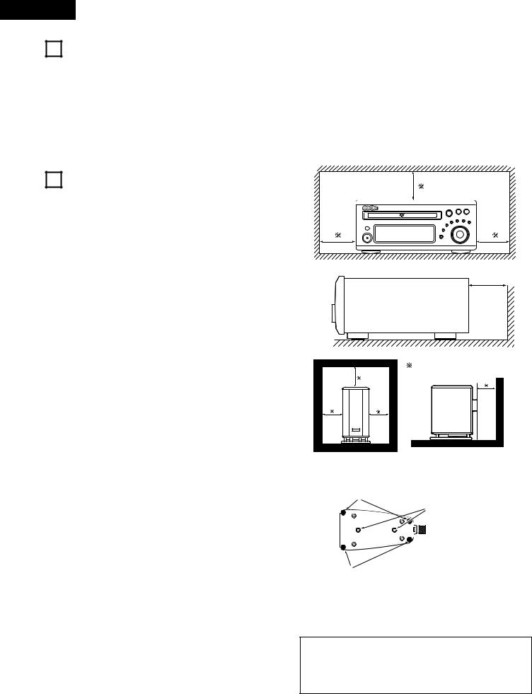
2CAUTIONS ON INSTALLATION
(1)DVD SURROUND RECEIVER
Noise or disturbance of the picture may be generated if this unit or any other electronic equipment using microprocessors is used near a tuner or TV.
If this happens, take the following steps:
•Install this unit as far as possible from the tuner or TV.
•Set the antenna wires from the tuner or TV away from this unit’s power cord and input/output connection cords.
•Noise or disturbance tends to occur particularly when using indoor antennas or 300 Ω /ohms feeder wires. We recommend using outdoor antennas and 75 Ω /ohms coaxial cables.
(2) SPEAKER SYSTEM (D-M51DVS only)
2 SC-A3L
The quality of the sound produced from the speaker system is affected by the size and type (Japanese or Western) of the room, as well as by the method of installation. Consider the points listed below before installing the speaker system.
•Note that placing the speaker system on the same stand or shelf as a record player may result in howling.
•If there is a wall, glass door, etc., directly in front of or behind the speaker system, cover the wall or door with a thick curtain to prevent resonance and reflection.
•The SC-A3L speaker systems are of the low-leakage-flux type and can be used near televisions, but depending on the TV there may be color blotching on the picture. If this happens, turn off the TV’s power, wait 15 to 30 minutes, then turn the TV’s power back on. The TV’s automatic degaussing circuit should reduce the blotching on the picture. If blotching persists, move the speaker further away.
•When placing the satellite speaker system (SC-A3L) on a stand, etc., stick the included anti-slip pads (cork, approximately 2 mm thick) at the four corners of the bottom surface. (Refer to the illustration below.)
•When mounting the satellite speaker system (SC-A3L) on a stand or bracket, M5 nuts are inserted into the bottom of the satellite speaker system (SC-A3L) at intervals of 60 mm. When mounting, following the instructions in the manual included with the speaker stand or ceiling mount bracket, and be sure to install properly and securely.
•When the satellite speaker system (SC-A3L) is mounted on a ceiling mount bracket, it is turned upside down due to the installation angle. The Denon mark is also turned upside down, so detach the speaker net and reattach it in the opposite direction.
2 DSW-3L
•Note that placing the active subwoofer on the same stand or shelf as a record player may result in howling.
•The DSW-3L active subwoofer is a Lowleakage-Flux type speaker system and can be used near televisions, but depending on the TV there may be color blotching on the picture. If this happens, turn off the TV’s power, move the TV and subwoofer a little apart, wait 15 to 30 minutes, then turn the TV’s power back on. The TV’s automatic degaussing circuit should reduce the blotching on the picture. If blotching persists, move the subwoofer and TV further away from each other.
•Install on a firm, flat floor to prevent accidents due to toppling down.
•Do not place a record player, CD player or other AV device on top of the subwoofer.
•Store this instructions in a safe place.
After reading, store this instructions along with the warranty in a safe place.
•Note that the illustrations in this instructions may differ from the actual set for explanation purposes.
For heat dispersal, leave at least 10 cm/4 inch of space between the top, back and sides of this unit and the wall or other
components. |
10 cm/4 inch or more |
10 cm/4 inch or more
Wall |
10cm/4inch or more
Wall
[ Satellite speaker system (illustration of bottom of SC-A3L) ]
Stick the anti-slip pads (cork, approximately 2 mm thick) here.
Speaker stand/speaker bracket mount screw holes
Stick the anti-slip pads (cork, approximately 2 mm thick) here.
CAUTION:
•To ensure safety, do not place any objects on top or lean objects against the speaker system.
•The speaker may topple down or fall if force is applied to the sides. Be particularly careful to avoid this, as this could cause injury or other serious accidents.
4

ENGLISH
WARNING:
•When installing the speaker systems on the ceiling or wall, to ensure safety, have specialists do the installation work.
•Be sure to fasten the speaker cords to a wall, etc., to prevent people from tripping over them or otherwise pulling on them accidentally, causing the speaker systems to fall.
•Be sure to check for safety after installing the speaker systems. Afterwards, perform safety inspections at regular intervals to be sure there is no danger that the speaker systems will fall. Denon will accept no responsibility for damages or accidents caused by inappropriate choice of the place of installation or improper installation procedures.
3CAUTIONS ON HANDLING
(1)DVD SURROUND RECEIVER
•Switching the input function when input jacks are not connected
A clicking noise may be produced if the input function is switched when nothing is connected to the input jacks. If this happens, either turn down the MASTER VOLUME control or connect components to the input jacks.
•Muting of PRE OUT jacks, HEADPHONE jack and SPEAKER terminals
The PRE OUT jacks, HEADPHONE jacks and SPEAKER terminals include a muting circuit. Because of this, the output signals are greatly reduced for several seconds after the power switch is turned on or input function, surround mode or any other-set-up is changed. If the volume is turned up during this time, the output will be very high after the muting circuit stops functioning. Always wait until the muting circuit turns off before adjusting the volume.
•Whenever the power switch is in the STANDBY state, the apparatus is still connected on AC line voltage. Please be sure to unplug the cord when you leave home for, say, a vacation.
(2) SPEAKER SYSTEM (D-M51DVS only)
2 SC-A3L
•Note that color blotching may occur on a TV, etc., due to interaction with the speaker system if there is a magnet or an object generating magnetic force nearby.
Examples: (a) When there are magnets on the door of the rack, stand, etc.
(b)When a health device, etc., equipped with magnets is placed nearby.
(c)When toys or other objects using magnets are placed nearby.
•Note that the illustrations in this instructions may differ from the actual set for explanation purposes.
•Be sure to keep the operating instructions.
After reading these operating instructions, store them in a safe place. We also recommend filling in the necessary items on the back cover.
2 DSW-3L
•The built-in amplifier of the active subwoofer (DSW-3L) includes a muting circuit. The output signal is strongly attenuated for several seconds after the power is turned on. If the volume is adjusted during this time, the output may be extremely high when the muting circuit is deactivated. Be sure to wait for the muting circuit to be deactivated before adjusting the volume.
•Note that color blotching may occur on a TV, etc., due to interaction with the subwoofer if there is a magnet or an object generating magnetic force nearby.
Examples: (a) When there are magnets on the door of the rack, stand, etc.
(b)When a health device, etc., equipped with magnets is placed nearby.
(c)When toys or other objects using magnets are placed nearby.
•Note that the illustrations in this instructions may differ from the actual set for explanation purposes.
•Be sure to keep the operating instructions.
After reading these operating instructions, store them in a safe place. We also recommend filling in the necessary items on the back cover.
WARNING:
•Be sure to fasten the power cord to a wall, etc., to prevent people from tripping over it or otherwise pulling on it accidentally, causing the subwoofer to fall.
4 FEATURES
The ADV-M51 combines an AV amplifier and DVD player, the core components of a home theater system, into a single compact, stylish body. The system takes up little space, and the aluminum front panel and half mirror of the display make for an elegant design that blends in nicely with the décor in your room.
1.2-channel power amplifier with Dolby Virtual Speaker
compatibility
The ADV-M51 is equipped with two 35W (6 Ω /ohms 1kHz, T.H.D. 10%) power amplifiers that make it compatible with new Dolby Virtual Speaker technology for recreating a 5.1-channel environment virtually using a 2-channel configuration. (Dolby Virtual Speaker is an proprietary technology of Dolby Laboratories.) A high performance digital signal processor enables playback of Dolby Digital and DTS multi-channel surround signals in the Dolby Virtual Speaker mode. Surround sound can be achieved with the Dolby Virtual Speaker mode for CDs and other 2-channel sources in combination with the Dolby Pro Logic II decoder.
2.DENON’s unique sound field simulation using the DSP
The ADV-M51 is compatible with the Rock Arena, Jazz Club and Video Game modes.
3.High performance DVD drive
The ADV-M51 is compatible with various functions offered by DVD sources, including multiple audio (up to 8 languages), multiple subtitle (up to 32 languages), multiple angle playback, viewing restriction, etc.
4.Quick setup and on-screen display compatibility
DVDs can be enjoyed simply by selecting the TV and speaker configuration to be used. The system can be set up using an onscreen display function.
5.Remote control unit with preset memory function
The ADV-M51 comes with a remote control unit equipped with a preset memory function including the remote control operation codes for D-M31 series MD recorders, cassette decks and DENON remote control compatible components as well as the remote control operation codes of other major brands of TVs and video decks.
6.Convenient system functions
When system connections are made with a D-M31 series MD recorder and cassette deck, such system functions as auto function selection, synchronized recording and timer recording/playback can be performed easily.
5
ENGLISH
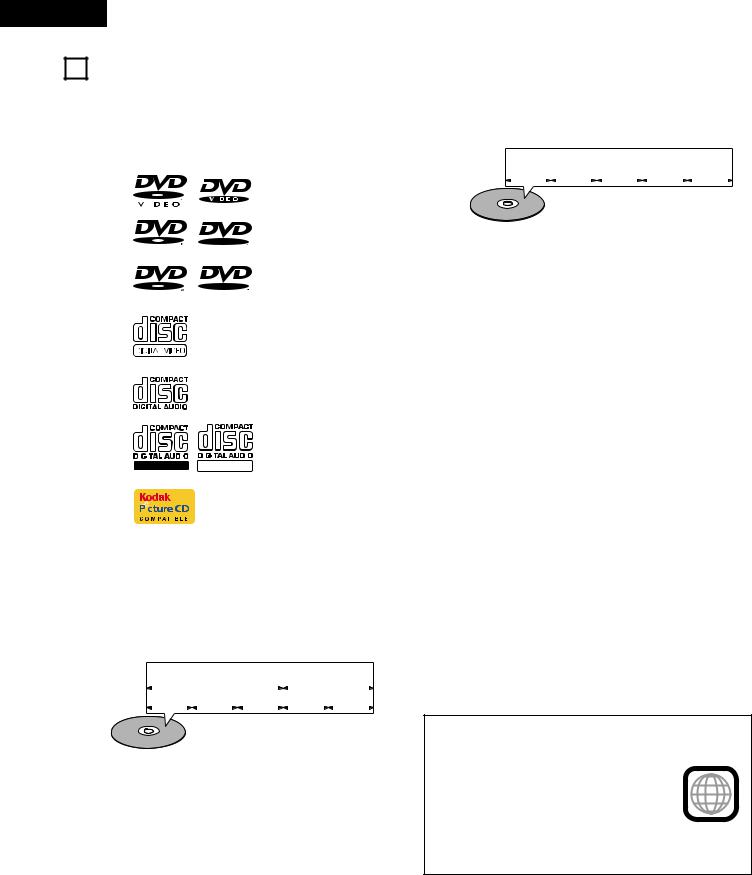
5DISCS
•The types of discs listed on the table below can be used on the ADV-M51. The marks are indicated on the disc labels or jackets.
Usable |
|
|
Mark (logo) |
Recorded |
Disc size |
|||||
discs |
|
|
signals |
|||||||
|
|
|
|
|
|
|
|
|
||
|
|
|
|
|
|
|
|
|
|
|
DVD video |
|
|
|
|
|
|
|
|
|
|
DVD audio |
|
|
|
|
|
|
|
|
|
12 cm |
(NOTE 1) |
|
|
|
|
|
|
|
|
Digital audio + |
|
|
|
|
|
|
|
|
|
|||
|
|
|
|
|
|
|
|
|
|
|
|
|
|
|
|
|
|
R |
digital video |
|
|
|
|
|
|
|
|
|
|
|||
DVD-R |
|
|
|
|
|
|
(MPEG2) |
|
||
|
|
R |
|
|||||||
DVD-RW |
|
|
|
|
|
|
|
|
|
|
(NOTE 2) |
|
|
|
|
|
|
|
|
|
8 cm |
|
|
|
|
|
|
|
|
|
|
|
|
|
|
|
|
|
|
R W |
|
|
|
|
|
|
R W |
|
|
|||||
|
|
|
|
|
|
|
|
|
|
|
|
|
|
|
|
|
|
|
|
Digital audio + |
12 cm |
|
|
|
|
|
|
|
|
|
|
|
Video CD |
|
|
|
|
|
|
|
|
digital video |
|
|
|
|
|
|
|
|
|
|
||
|
|
|
|
|
|
|
|
|
(MPEG1) |
8 cm |
|
|
|
|
|
|
|
|
|
|
|
|
|
|
|
|
|
|
|
|
|
|
|
|
|
|
|
|
|
|
|
Digital audio |
12 cm |
CD |
|
|
|
|
|
|
|
|
|
|
|
|
|
|
|
|
|
|
MP3 |
|
|
CD-R |
|
|
|
|
|
|
|
|
|
|
|
|
|
|
|
|
|
|
WMA |
|
|
CD-RW |
|
|
|
|
|
|
|
|
|
|
|
|
|
|
|
|
|
|
Digital picture |
|
|
(NOTE 3) |
|
|
|
|
|
|
|
|
|
|
|
|
|
|
|
|
|
|
(JPEG) |
|
|
|
|
|
|
|
|
|
|
|
8 cm |
|
|
|
|
|
|
|
|
|
|
|
|
|
|
|
|
|
|
|
|
|
|
|
|
Recordable ReWritable |
|
|
|||||||
|
|
|
|
|
|
|
|
|
|
|
Picture CD |
|
|
|
|
|
|
|
|
Digital picture |
12 cm |
|
|
|
|
|
|
|
|
(JPEG) |
||
|
|
|
|
|
|
|
|
|
|
|
|
|
|
|
|
|
|
|
|
|
|
|
|
|
|
|
|
|
|
|
|
|
For example:
Track 1 |
|
|
|
Track 2 |
|
|
|
Track 3 |
|
|
Track 4 |
|
|
Track 5 |
2The following types of discs cannot be played on the ADVM51:
•DVDs with region numbers other than “2” or “ALL”
•DVD audio discs (NOTE 1)
•DVD-ROM/RAMs
•CVD
•CD-ROMs (Only MP3/WMA file can be played)
•VSDs
•CDVs (Only the audio part can be played.)
•CD-Gs (Only the audio is output.)
•Photo CDs (NEVER play such discs on the ADV-M51)

 If you attempt to play photo CDs, the data on the disc may be damaged.
NOTE 1: Video part which based on DVD-video specification only can be played.
NOTE 2: Playing DVD-R and DVD-RW discs
DVD-R and DVD-RW discs recorded in video format on a DVD recorder can be played on the ADV-M51.
Discs that have not be finalized cannot be played. Depending on the disc’s recording status, the disc may not be accepted or may not be played normally (the picture or sound may be not be smooth, etc.).
2Disc terminology
•Titles and chapters (DVD-videos)
DVD-videos are divided into several large sections called “titles” and smaller sections called “chapters”.
Numbers are allotted to these sections. These numbers are called “title numbers” and “chapter numbers”.
For example:
|
|
|
Title 1 |
|
Title 2 |
|||||
|
|
|
|
|
|
|
|
|
|
|
Chapter 1 Chapter 2 Chapter 3 |
|
Chapter 1 Chapter 2 |
||||||||
|
|
|
|
|
|
|
|
|
|
|
|
|
|
|
|
|
|
|
|
|
|
•Tracks (video and music CDs)
Video and music CDs are divided into sections called “tracks”. Numbers are allotted to these sections. These numbers are called “track numbers”.
NOTE 3: According to recording quality, some CD-R/RW cannot be played.
•Playback control (video CDs)
Video CDs including the words “playback control” on the disc or jacket are equipped with a function for displaying menus on the TV screen for selecting the desired position, displaying information, etc., in dialog fashion.
In this manual, playing video CDs using such menus is referred to “menu playback”.
Video CDs with playback control can be used on the ADV-M51.
NOTE:
• This DVD video player is designed and
manufactured to respond to the Region |
|
|
Management Information that is recorded on |
|
|
a DVD disc. |
2 |
|
If the Region number described on the DVD |
||
|
||
disc does not correspond to the Region |
|
|
number of this DVD video player, this DVD |
|
|
video player cannot play this disc. |
|
|
The Region number for this DVD video player |
|
|
is 2. |
|
6
6 CAUTIONS ON HANDLING DISCS
Discs
Only the discs including the marks shown on page 6 can be played on the ADV-M51.
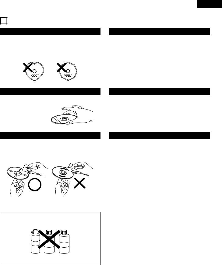
Note, however, that discs with special shapes (heart-shaped discs, hexagonal discs, etc.) cannot be played on the ADV-M51. Do not attempt to play such discs, as they may damage the player.
ENGLISH
Cautions on Handling Discs
•Do not get fingerprints, grease or dirt on discs.
•Be especially careful not to scratch discs when removing them from their cases.
•Do not bend discs.
•Do not heat discs.
•Do not enlarge the center hole.
•Do not write on the labeled (printed) side with a ball-point pen or a pencil.
•Water droplets may form on the surface if the disc is moved suddenly from a cold place to a warm one. Do not use a hairdryer, etc., to dry the disc.
Holding Discs
Avoid touching the surface of discs when loading and unloading them.
Be careful not to get fingerprints on the signal surface (the side which shines in rainbow colors).
Cautions on Storing Discs
•Always eject discs after playing them.
•Keep discs in their cases to protect them from dust, scratches and warping.
•Do not put discs in the following places:
1.Places exposed to direct sunlight for long periods of time
2.Humid or dusty places
3.Places exposed to heat from heaters, etc.
Cleaning Discs
2Fingerprints or dirt on the disc may lower sound and picture quality or cause breaks in playback. Wipe off fingerprints or dirt.
2Use a commercially available disc cleaning set or a soft cloth to wipe off fingerprints or dirt.
Wipe gently from the middle |
Do not wipe with a circular |
outwards. |
motion. |
NOTE:
•Do not use record spray or antistatic. Also do not use volatile chemicals such as benzene or thinner.
Record Thinner Benzene
spray
Cautions on Loading Discs
•Only load one disc at a time. Loading one disc on top of another may result in damage or scratch the discs.
•Load 8 cm discs securely in the disc guide, without using an adapter. If the disc is not properly loaded, it may slip out of the guide and block the disc tray.
•Be careful not to let your fingers get caught when the disc tray is closing.
•Do not place anything but discs in the disc tray.
•Do not load cracked or warped discs or discs that have been fixed with adhesive, etc.
•Do not use discs on which the adhesive part of cellophane tape or glue used to attach the label is exposed, or discs with traces of tape or labels that have been peeled off. Such discs may get stuck inside the player, resulting in damage.
7
ENGLISH
7 CONNECTIONS
•Do not plug in the AC cord until all connections have been completed.
•Be sure to connect the left and right channels properly (left with left, right with right).
•Insert the plugs securely. Incomplete connections will result in the generation of noise.
•Note that binding pin plug cords together with AC cords or placing them near a power transformer will result in generating hum or other noise.
•Noise or humming may be generated if a connected audio equipment is used independently without turning the power of this unit on. If this happens, turn on the power of the this unit.
(1) Connecting the audio components (D-M31 series)
•The ADV-M51 can be used connected in a system with the D-M31 series MD recorder (DMD-M31) and cassette deck (DRR-M31).
•For instructions on operating the separately sold MD recorder (DMD-M31) and cassette deck (DRR-M31), refer to their respective operating instructions.
•Only the DMD-M31 MD recorder and DRR-M31 cassette deck can be connected directly to the ADV-M51 using system connections.
NOTE:
•This system includes digital circuitry which may cause interference such as color blotching or changes in the color on TVs. If this happens, move the system and the TV as far apart as possible.
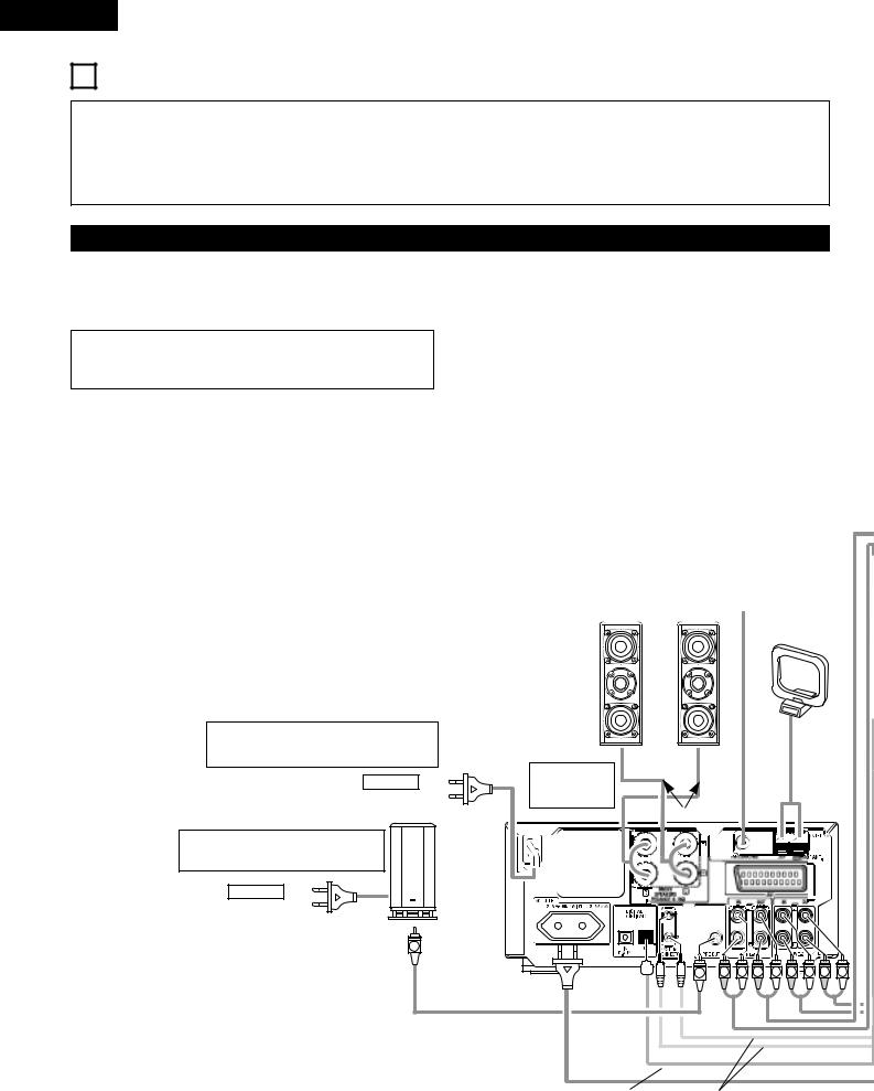
Connecting the speaker systems
Connect the speaker system for the left channel (the left side as seen from the front) to the L terminals, the speaker system for the right channel to the R terminals. Refer to the instructions supplied with the speaker system for details. Be sure to use speaker systems with an impedance of 6 Ω /ohms or greater.
The ADV-M51 includes a built-in clock function, so plug its power cord into a wall power outlet to which electricity is supplied constantly.
AC CORD
AC 230 V, 50 Hz
DSW-3L (D-M51DVS only) or commercially available subwoofer with built-in amplifier
AC CORD
AC 230 V, 50 Hz
Speaker system |
|
|
SC-A3L (D-M51DVS only) |
FM indoor antenna |
|
or commercially available |
(included) |
|
speaker |
|
|
AM loop antenna (included)
(R)
ADV-M51 DVD
surround receiver
Speaker cords
SUB WOOFER
R |
L |
R |
Audio cord
Optical transmission |
System cords |
cables |
|
8
ENGLISH
CAUTION:
•Only one MD recorder and one cassette deck can be connected to the ADV-M51 using system connections. System operations cannot be performed properly if two MD recorders or two cassette decks are connected using system connections.
•Whenever the power operation switch is in the STANDBY position, the unit is still connected to AC line voltage.
•Please be sure to unplug the power cord when you leave home for, e.g.,a vacation, etc.
System operations
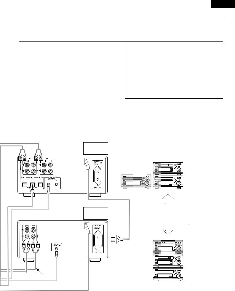
Such system operations as the timer and the auto power on functions, as well as remote control operations cannot be performed unless all the RCA pin-plug cords and system connector cords are connected between the units, so be sure to make all the connections properly as shown in the diagram. Also, disconnecting system connectors while the system is operating may result in malfunctions. Be sure to unplug the power cord before changing connections.
Stereo audio cord
MD recorder (DMD-M31)
(sold separately)
ADV-M51
Cassette deck (DRR-M31)
(sold separately)
NOTES:
•Do not plug the power cord into the power outlet until all connections are completed. Be sure to interconnect the channels (L to L (white) and R to R (red)) properly, as shown on the diagram.
•Use the AC OUTLET for audio equipment only. Do not use them for hair driers, etc.
•Insert the plugs securely. Incomplete connections may result in noise.
•Be sure to connect the speaker cords between the speaker terminals and the speaker systems with the same polarities ( + to +, – to – ). If the polarities are switched, the sound at the center will be weak, the position of the different instruments will be unclear, and the stereo effect will be lost.
•After unplugging the power cord, wait about 5 seconds before plugging it back in.
•Note that setting the connection cords (pin-plug cords) next to the power cords may result in humming or other noise.
DMD-M31
DRR-M31
(Horizontal installation)
Install the sets as shown in one of these diagrams. In either case, be sure that the DVD surround receiver’s ventilation holes are not obstructed.
R |
L |
R |
L |
ADV-M51 |
|
|
|
|
DMD-M31 |
|
|
Stereo audio cord |
DRR-M31 |
|
|
|
|
||
(Vertical installation)
9
ENGLISH
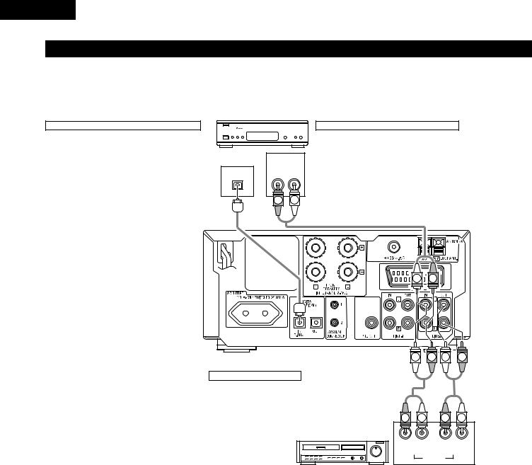
(2) Connecting the Audio Signals of a Digital Satellite Tuner and VCR
•Connect the video signals directly to the TV and switch the picture on the TV.
•When making connections, also refer to the operating instructions of the other components.
Connection to the optical digital input terminal
•Only audio signals are input to the optical digital input terminal.
•Use a commercially available optical transmission cable for connection to the optical transmission terminal (OPTICAL).
Digital satellite/cable tuner
B
OPTICAL |
AUDIO |
OUT |
OUT |
R L |
Connection of a digital satellite/cable tuner
•For tuners equipped with an optical digital output terminal, connect the digital output terminal to the DIGITAL D.AUX IN terminal on the ADV-M51 using an optical transmission cable.
•To connect the audio output terminals, use whatever of the ADV-M51’s LINE-1 or LINE-2 terminals are open.
R L
L |
R |
SUB WOOFER
L |
R |
L |
R |
Connection of a video deck
•Connect the video deck’s audio output and audio input terminals to whatever of the ADV-M51’s LINE-1 or LINE-2 terminals are open using pin-plug cords.
R |
L |
R |
L |
Video deck |
|
|
|
R |
L |
R |
L |
OUT |
|
IN |
|
|
|
AUDIO |
|
10
ENGLISH
(3) Connecting a TV
•Use the commercially 21-pin SCART cable to connect the TV’s 21-pin SCART terminal to the ADV-M51’s 21-pin SCART terminal (AV1).
Monitor TV
SUB WOOFER
•The audio and video signals for the function selected on the set are output.
Audio output signals
•The tuner and DVD audio playback signals and the audio signals input to the AUDIO INPUT jacks are output.
•When Dolby Digital and DTS DVD are played, the audio signals are converted to 2-channel signals before being output.
•The audio output level is fixed. If you do not wish to play the sound on the connected TV, turn the TV’s volume down to the minimum.
Video output signals (Function “DVD” only)
•The DVD video playback signals is output.
•The selection of the VIDEO, S-VIDEO and RGB video signals is set at “AV1 VIDEO OUTPUT” system setup item. (By default all are set to “VIDEO”. See page 29.)
NOTES:
•Connect this unit video outputs to the TV either directly. Do not connect it via a VCR (video cassette recorder). Some discs contain copy prohibit signals. If such discs are played via a VCR, the copy prohibit system may cause disturbance in the picture.
•Set the “TV TYPE” in “VIDEO SETUP” in “DVD SETUP” to comply with your TV’s video format. When the TV is PAL formated, set to PAL. (See page 29.)
•The factory default is “PAL”. When in the stop mode with the function set to “DVD”, the setting can also be switched with the
“NTSC/PAL” button on the remote control unit. If the setting does not match your TV’s video format, switch it from the remote control unit, then set “TV TYPE” under “VIDEO SETUP” at “DVD SETUP” to the setting match your TV’s video format.
11
ENGLISH
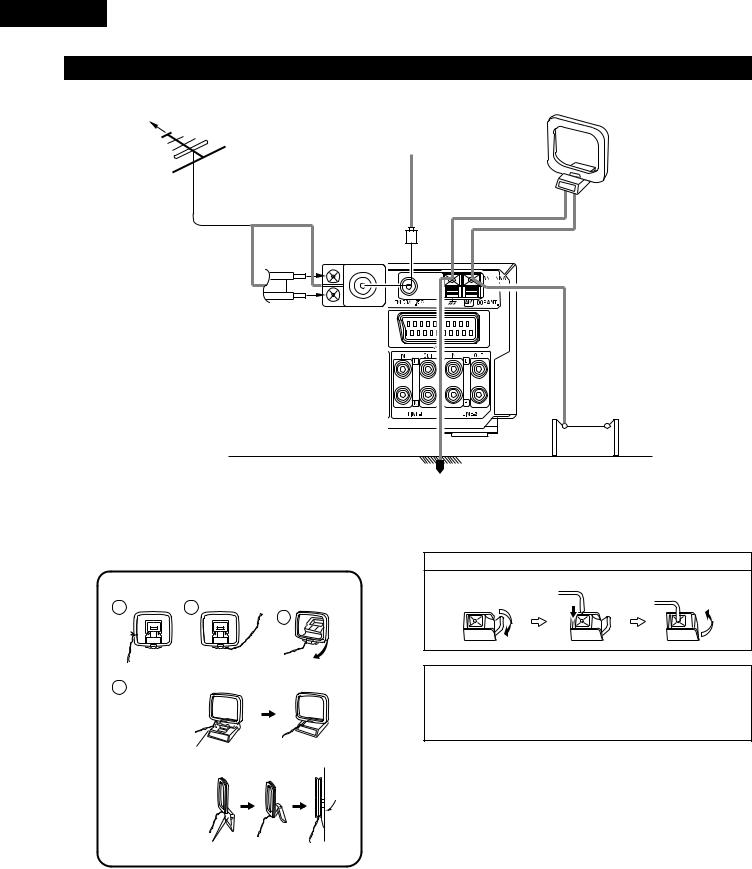
(4) Connecting the antenna terminals
DIRECTION OF |
AM LOOP ANTENNA |
BROADCASTING |
(Supplied) |
STATION |
|
|
FM INDOOR ANTENNA |
|
(Supplied) |
FM ANTENNA |
|
75 Ω |
/ohms |
COAXIAL |
|
CABLE |
|
FM ANTENNA ADAPTER (Option)
AM OUTDOOR
ANTENNA
GROUND
•An PAL-type FM antenna cable plug can be connected directly.
•If the FM antenna cable’s plug is not of the PAL-type, connect using the PAL-type antenna adapter (Option).
AM loop antenna assembly
1 |
2 |
Remove the vinyl tie and take out the
connection line.
4
a.With the antenna on top any stable
surface.
Mount
b.With the antenna attached to a wall.
Connect to the AM antenna terminals.
3
Bend in the reverse direction.
Connection of AM antennas
1. Push the lever. |
2. Insert the conductor. |
3. Return the lever. |
|||
|
|
|
|
|
|
|
|
|
|
|
|
|
|
|
|
|
|
|
|
|
|
|
|
|
|
|
|
|
|
NOTES:
•Do not connect two FM antennas simultaneously.
•Even if an external AM antenna is used, do not disconnect the AM loop antenna.
•Make sure AM loop antenna lead terminals do not touch metal parts of the panel.
Installation hole Mount on wall, etc.
12

ENGLISH
(5) Sound output from this unit digital and analog audio output connectors
2 When a disc is played on the ADV-M51 (DIGITAL OUT)
|
|
|
|
Settings |
Refer to |
Digital audio data output |
|
Audio recording format |
page |
||||
|
|
|
||||
|
|
|
|
|||
|
|
|
|
|
|
|
|
|
Dolby Digital |
Digital out : Normal |
|
Dolby Digital bitstream |
|
|
|
|
|
|
||
|
|
Digital out : PCM conversion |
98 |
2 channels PCM data (48 kHz/16bit) |
||
|
|
|
|
|||
|
|
|
|
|
|
|
|
|
|
DTS |
Digital out : Normal |
DTS bitstream |
|
|
|
|
|
|||
|
|
|
|
|
|
|
|
|
|
Digital out : PCM conversion |
|
2 channels PCM data (48 kHz/16bit) |
|
|
|
|
|
|
||
|
|
|
|
|
|
|
DVD video |
|
MPEG audio |
Digital out : Normal |
98 |
2 channels PCM data (48 kHz/16bit) |
|
|
|
|
||||
|
Digital out : PCM conversion |
2 channels PCM data (48 kHz/16bit) |
||||
DVD audio |
|
|
|
|
||
(video part only) |
|
|
|
|
|
|
|
|
48 kHz |
LPCM conversion mode : OFF |
|
48 kHz/16 ~24 bit PCM |
|
|
|
|
|
|||
|
|
|
|
|
|
|
|
PCM |
|
LPCM conversion mode : ON |
|
48 kHz/16 bit PCM |
|
|
|
|
|
|||
|
|
|
|
|
|
|
|
|
96 kHz |
LPCM conversion mode : ON |
98 |
48 kHz/16 bit PCM |
|
|
Linear |
|
||||
|
|
|
|
|
|
|
|
|
CP : ON |
LPCM conversion mode : OFF |
|
48 kHz/16 bit PCM (when copy-protected) |
|
|
|
|
|
|
|
|
|
|
|
CP : OFF |
LPCM conversion mode : OFF |
|
96 kHz PCM (when not copy-protected) |
|
|
|
|
|
|
|
Video CD |
|
MPEG 1 |
|
|
44.1 kHz/16 bit PCM |
|
|
|
|
|
|
|
|
Music CD |
|
Linear PCM |
|
|
44.1 kHz/16 bit PCM |
|
|
|
|
|
|
|
|
MP3/WMA CD |
|
MP3/WMA |
|
|
32 ~ 48 kHz/16 bit PCM |
|
|
|
|
|
|
|
|
•Linear PCM audio is the signal recording format used for music CDs.
While the signals are recorded at 44.1 kHz/16 bit for music CDs, for DVDs they are recorded at 48 kHz/16 bit to 96 kHz/24 bit, providing higher sound quality than music CDs.
2 About the LINE-1 and LINE-2 analog recording outputs
When the DVD or the D.AUX digital input is selected:
•Dolby Digital, DTS and PCM digital signals are automatically converted to 2-channel stereo signals before being output (except when in the Dolby Headphone mode) and can be recorded in analog. (For what happens in the Dolby Headphone mode, see below.)
When TUNER, LINE-1 or LINE-2 is selected:
•The selected analog audio signals from the tuner or from the device connected to the LINE-1 or LINE-2 analog input terminals (IN) are output unchanged, regardless of the ADV-M51’s input mode or surround mode. (The same is true for the device connected to the D.AUX terminals when “LINE-2” under “⁄0SETTING UP THE SYSTEM – (3) Detailed system setup – [6] Function settings” is set to “D.AUX”.)
Recording output during playback of a DVD or D.AUX digital input source in the Dolby Headphone mode:
•In the Dolby Headphone mode with a DVD or a digital input selected, the Dolby Headphone mode analog audio signals currently being played are output and can be recorded in analog. (See pages 58 and 59.)
Cautions during analog recording of DVDs or digital input sources:
•Do not switch the ADV-M51’s input mode, surround mode or surround parameters during recording. Doing so will interrupt the sound being recorded.
We recommend setting the surround mode to “STEREO” or “DIRECT”.
•When using headphones, recording is automatically performed in the Dolby Headphone mode. Do not disconnect the headphones or switch the headphones mode during recording.
13
ENGLISH
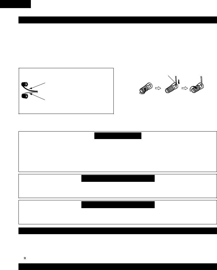
(6) Speaker system connections
Be sure to turn the amplifier’s power off when connecting the speaker systems.
•Use the included cables to connect the input terminals on the back of the speaker systems (see diagram) to the amplifier’s speaker output terminals. Connect the speaker system for the left channel amplifier’s “L” terminals, the one for the right channel to the amplifier’s “R” terminals, matching the polarities (“≈” and “√” marks). Inverting the polarities will result in unnatural sound, with the phase off or no low bass sound. Also check that all two terminal knobs are tightly fastened.
The red side is the “+” side, the black side
the “–” side.
To “+” side on amplifier (copper colored core
wire)
NOTE: Make sure the core wires do not
touch each other.
To “–” side on amplifier (silver colored core
wire)
Connecting the speaker cords
Use the included connection cords to connect the input terminals on the backs of the speaker systems (see the diagram at the right) to the ADV-M51’s speaker output terminals.
•Connect the speaker system for the left channel to the “L” terminals, the speaker system for the right channel to the “R” terminals, and be sure the polarities (“+” and “–”) are properly interconnected.
•Note that if the polarities are inverted, the phase may be off and the bass sound may be missing, resulting in an unnatural sound. Also check that both the speaker terminal’s screws are tightly screwed.
Either twist the core wires firmly or terminate the wires.
qTurn the speaker |
wInsert the cord’s |
eTurn clockwise to |
terminal |
core wires. |
tighten the |
counterclockwis |
|
terminal. |
e to loosen it. |
|
|
Protector circuit
•This unit is equipped with a high-speed protection circuit. The purpose of this circuit is to protect the speakers under circumstances such as when the output of the power amplifier is inadvertently short-circuited and a large current flows, when the temperature surrounding the unit becomes unusually high, or when the unit is used at high output over a long period which results in an extreme temperature rise.
When the protection circuit is activated, the speaker output is cut off and the power supply indicator LED flashes. Should this occur, please follow these steps: be sure to switch off the power of this unit, check whether there are any faults with the wiring of the speaker cables or input cables, and wait for the unit to cool down if it is very hot. Improve the ventilation condition around the unit and switch the power back on.
If the protection circuit is activated again even though there are no problems with the wiring or the ventilation around the unit, switch off the power and contact a DENON service center.
Note on speaker impedance
•The protector circuit may be activated if the set is played for long periods of time at high volumes when speakers with an impedance lower than the specified impedance (for example speakers with an impedance of lower than 4 Ω /ohms) are connected. If the protector circuit is activated, the speaker output is cut off. Turn off the set’s power, wait for the set to cool down, improve the ventilation around the set, then turn the power back on.
Cautions on connecting
•With this unit’s speaker outputs, signals with the reverse phase of the “+” side output terminal’s signals are also output from the “-” side output terminal.
Do not connect to a device for switching between multiple speakers (a speaker selector or audio channel selector) or connect in ways other than described in this manual. Doing so will result in damage.
(7)Using the active subwoofer (DSW-3L) (D-M51DVS only)
1.Set the power switch to the “ON” position.
• When the unit’s AC power cord is plugged into a switched AC outlet on the amplifier, if the power switch is left at the “ON” position, the unit’s power turns on and off automatically when the amplifier’s power is turned on and off.
• If the AC power cord is not plugged into a switched AC outlet on the amplifier, set the unit’s power switch to the “ON” position after turning on the amplifier’s power. When turning the power off, set the unit’s power switch to the “OFF” position before turning off the amplifier’s power.
2.Adjust the volume using the volume adjustment control.
For details, see “PART NAMES AND FUNCTIONS”.
(8) Removing the speaker net (SC-A3L) (D-M51DVS only)
*The net on the front of the speaker systems (SC-A3L) can be removed.
•To remove, grasp both sides of the net and pull forward.
•To mount, line up the holes in the four corners of the speaker net with the projecting pieces in the four corners of the cabinet and press in.
14
ENGLISH
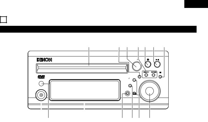
8 PART NAMES AND FUNCTIONS
DVD SURROUND RECEIVER (ADV-M51) Front Panel
• For details on the functions of these parts, refer to the pages given in parentheses ( ).
!4 |
!3!2 !1!0o i |
|
DVD SURROUND RECEIVER ADV-M51 |
SURROUND SELECT |
|
PUSH-PARAM |
|
|
|
MENU SET |
BAND |
|
|
|
V I D E O |
TONE SDB |
VOLUME |
|
||
FUNCTION
ON STANDBY
PHONES
|
|
|
|
|
|
|
|
q w |
e |
||
q Power operation switch (ON/STANDBY).................................. |
(30) |
||
w Remote control sensor............................................................. |
(20) |
||
e Display |
|
|
|
r Headphones jack (PHONES) .................................................... |
(58) |
||
t Function selector (FUNCTION)................................................. |
(44) |
||
y Tone/super dynamic bass button (TONE/SDB) ........................ |
(46) |
||
u Volume control (VOLUME) ....................................................... |
(42) |
||
r ty u
i Stop/band button ( 2 BAND).............................................. |
(42, 60) |
o Play/pause button ( 13 ) ................................................... |
(41, 43) |
!0Open/close button ( 5 ) .......................................................... |
(41) |
!1Skip backward and forward buttons |
|
( 8 / – and + / 9 ) ..................................................... |
(43, 60) |
!2Surround/select knob (SURROUND/SELECT) .......................... |
(50) |
Surround parameter button (PARAMETER) ............................. |
(51) |
!3Menu/set button (MENU/SET) ................................................. |
(62) |
!4Disc holder ............................................................................... |
(40) |
15
ENGLISH
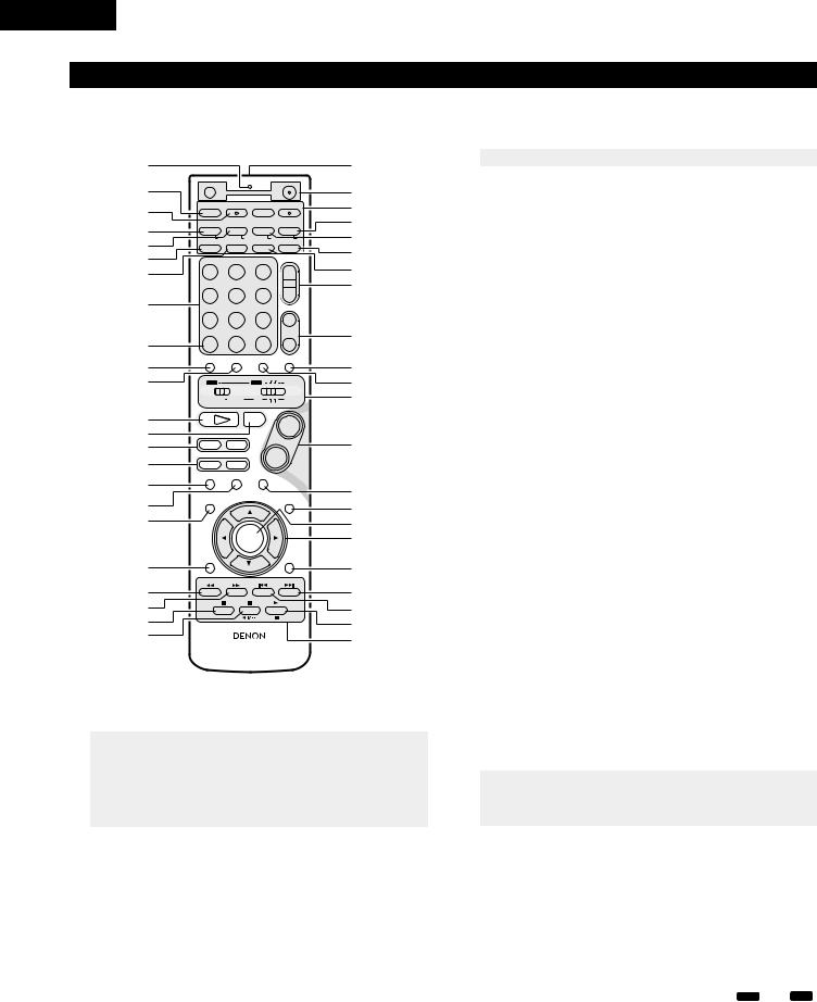
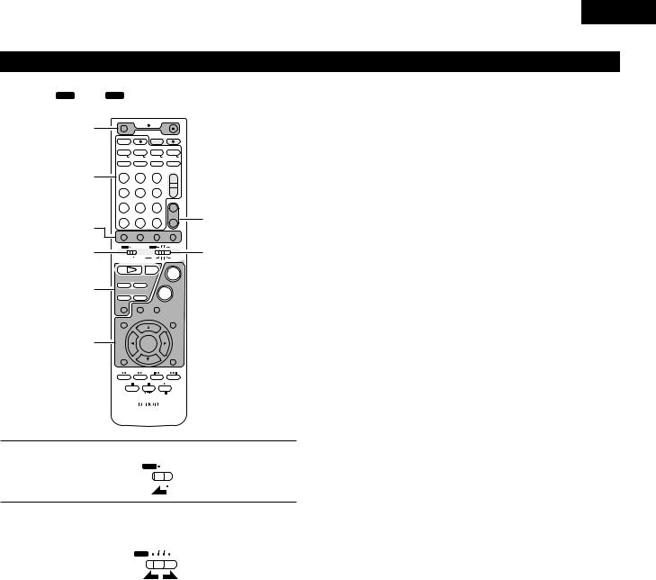
Remote control unit
•For details on the functions of these parts, refer to the pages given in parentheses ( ).
•Some of the buttons on the remote control unit have some functions.
The functions are switched using the remote control mode selector switches.
q |
|
|
|
|
@4 |
|
w |
OFF |
|
ON |
@5 |
||
|
|
VCR |
|
|
|
|
|
SLEEP |
REC |
TITLE |
TIME |
@6 |
|
e |
NTSC/PAL |
|||||
|
||||||
SOURCE |
|
TV IN |
T V |
@7 |
||
|
CLEAR |
ENTER |
CHARAC. |
EDIT/MENU |
||
r |
A-B REPEAT |
SLIDE MODE |
ZOOM |
|||
RDS |
PTY |
TV CH - |
TV CH + |
@8 |
||
|
CT |
CD SRS RT |
||||
t |
PROG/DIRECT |
REPEAT |
RANDOM |
SEARCH MODE |
||
MODE |
MEMO |
BAND |
TUNING / |
@9 |
||
y |
DVD |
TUNER |
D.AUX |
TV VOL |
|
|
u |
1 |
2 |
3 |
+ |
#0 |
|
|
MD/LINE - 1 |
TAPE /LINE-2 |
|
- |
#1 |
|
i |
4 |
5 |
6 |
|
||
|
5CH STEREO |
AUTO DECODE |
TUNER |
|
||
|
7 |
8 |
9 |
+ |
#2 |
|
|
DIRECT |
STEREO |
VIRTUAL |
CH |
||
o |
CALL |
0/10 |
+10 |
- |
|
|
!0 |
TEST TONE |
INPUT MODE |
SURROUND |
FUNCTION |
#3 |
|
|
|
|
|
|||
!1 |
|
|
TUNER TV / VCR |
#4 |
||
|
A / V |
|
DVD |
IN/SURR. |
|
|
|
|
SYSTEM |
MD |
IN/SURR. |
#5 |
|
|
|
|
CDR TAPE |
|
||
!2 |
1 |
|
2 |
+ |
|
|
!3 |
DVD |
|
|
|
||
|
|
|
#6 |
|||
!4 |
8 |
9 |
|
|
||
!5 |
6 |
7 |
- |
|
||
|
|
|
|
|
||
!6 |
|
STATUS |
|
|
|
|
3 |
|
MUTING |
#7 |
|||
|
SETUP |
|
|
TONE /SDB |
||
!7 |
|
|
|
|||
|
|
|
|
#8 |
||
!8 |
|
|
|
|
#9 |
|
|
|
|
|
|
||
|
|
ENTER |
|
$0 |
||
|
CH SELECT |
|
|
SURROUND |
|
|
|
|
|
PARAMETER |
|
||
!9 |
|
|
- VCR CH + |
$1 |
||
@0 |
|
|
$2 |
|||
RETURN |
DISPLAY |
MENU |
TOP MENU |
|||
@1 |
ANGLE AUDIO SUB TITLE |
$3 |
||||
@2 |
|
|
|
|
$4 |
|
@3 |
|
|
|
|
||
|
RC-966 |
|
$5 |
|||
|
|
|
||||
q Transmission indicator |
|
|
|
|
||
w Sleep timer button |
................................................................... |
|
|
|
(90) |
|
e NTSC/PAL button ..................................................................... |
|
|
|
|
(11) |
|
r Clear button.............................................................................. |
|
|
|
|
(70) |
|
t A-B repeat button..................................................................... |
|
|
|
|
(69) |
|
y Program/direct.......................................................................... |
|
|
|
|
(70) |
|
u Repeat button........................................................................... |
|
|
|
|
(68) |
|
iInput source/surround mode selector button
*System buttons ............................................(18, 21, 22, 23, 28)
o
!0Test tone button ....................................................................... |
(36) |
|
!1Input mode selector button...................................................... |
(44) |
|
!2DVD play button ....................................................................... |
(41) |
|
!3DVD stop button ...................................................................... |
(42) |
|
!4DVD skip buttons ..................................................................... |
(43) |
|
!5DVD search buttons ........................................................... |
(43, 44) |
|
!6DVD pause button.................................................................... |
(43) |
|
!7Status button............................................................................ |
(45) |
|
!8Setup button............................................................................. |
(30) |
|
!9Channel select button .............................................................. |
(36) |
|
|
|
|
@0 |
Return button ........................................................................... |
(42) |
@1 |
Display button .......................................................................... |
(66) |
@2 |
Angle button............................................................................. |
(80) |
@3 |
Audio selector button............................................................... |
(78) |
@4Remote control signal transmission window........................... |
(20) |
|
@5Power button............................................................................ |
(30) |
|
@6* System buttons......................................................... |
(18, 21, 22) |
|
|
|
|
@7 |
Zoom button............................................................................. |
(83) |
@8 |
Slide mode button.................................................................... |
(77) |
@9 |
Search mode button................................................................. |
(43) |
#0 |
Random button......................................................................... |
(71) |
#1Tuner tuning +/– buttons .......................................................... |
(60) |
|
#2Tuner preset +/– buttons.......................................................... |
(61) |
|
#3Function selector button .......................................................... |
(44) |
|
#4Surround mode selector button ............................................... |
(45) |
|
#5Mode selector switches..................................................... |
(17, 18) |
|
#6Main volume control buttons ................................................... |
(42) |
|
#7Muting button........................................................................... |
(46) |
|
#8Tone/SDB button ...................................................................... |
(46) |
|
#9Enter button ............................................................................. |
(29) |
|
$0Cursor button ........................................................................... |
(29) |
|
$1Surround parameter button...................................................... |
(50) |
|
......................................................................$2Top menu button |
(81) |
|
$3Menu button............................................................................. |
(82) |
|
$4Subtitle button.......................................................................... |
(79) |
|
...................................................$5* System buttons |
(18, 21, 22, 28) |
|
• |
For details on the function and operation of the various parts, refer to the pages indicated in (parentheses). |
||
• |
Buttons indicated |
|
are DVD control buttons and can be operated when the remote control mode selector switch is set to the A / V and DVD |
|
position. |
|
|
• |
The functions of the system buttons (*) are switched using the remote control mode selector switch. |
||
16
ENGLISH
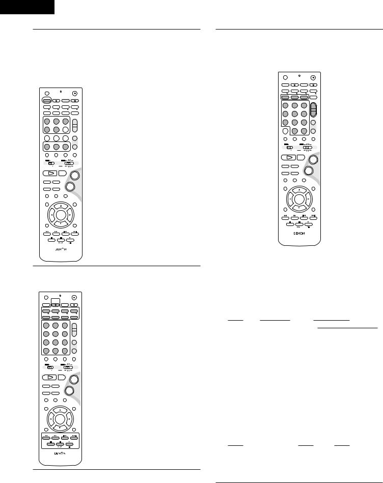
Names and functions of remote control unit buttons on the ADV-M51
• Buttons in sections q ~ e can be operated regardless of the position of mode switches 1 and 2.
• Consider A / V and DVD as standard positions, and switch as necessary to operate.
q |
OFF |
|
|
|
ON |
|
|
|
|
|
VCR |
|
|
|
|
|
|
SLEEP |
|
REC |
TITLE |
TIME |
|
|||
|
NTSC/PAL |
|
||||||
|
SOURCE |
|
|
TV IN |
T |
V |
|
|
|
CLEAR |
|
ENTER |
CHARAC. |
EDIT/MENU |
|
||
|
A-B REPEAT |
SLIDE MODE |
ZOOM |
|
||||
|
|
|
|
TV CH - |
TV CH + |
|
||
|
RDS |
|
PTY |
|
CT |
CD SRS RT |
|
|
|
PROG/DIRECT |
|
REPEAT |
RANDOM |
SEARCH MODE |
|
||
|
MODE |
|
MEMO |
BAND |
|
|
|
|
3 |
|
|
|
|
|
TUNING / |
|
|
DVD |
|
TUNER |
D.AUX |
TV VOL |
|
|||
1 |
|
2 |
3 |
+ |
|
|||
|
|
|
|
|
||||
|
MD/LINE-1 |
TAPE /LINE-2 |
|
|
- |
|
||
|
4 |
|
5 |
6 |
|
|||
|
|
5CH STEREO |
AUTO DECODE |
TUNER |
|
|||
|
7 |
|
8 |
9 |
+ |
e |
||
|
DIRECT |
|
STEREO |
VIRTUAL |
|
CH |
||
q |
CALL |
|
0/10 |
+10 |
- |
|||
TEST TONE |
INPUT MODE |
SURROUND |
FUNCTION |
|
||||
1 |
|
|
|
TUNER TV / VCR |
|
2 |
||
A / V |
|
|
DVD |
|
IN/SURR. |
|||
|
SYSTEM |
MD |
CDR TAPE IN/SURR. |
|||||
|
1 |
|
|
2 |
|
+ |
|
|
|
DVD |
|
|
|
|
|
||
w |
8 |
|
9 |
|
|
|
|
|
6 |
|
7 |
|
- |
|
|
||
|
|
|
STATUS |
|
|
|
|
|
|
3 |
|
|
|
MUTING |
|
|
|
|
SETUP |
|
|
|
|
TONE /SDB |
|
|
q |
|
|
ENTER |
|
|
|
|
|
|
CH SELECT |
|
|
|
|
SURROUND |
|
|
|
|
|
|
|
PARAMETER |
|
||
|
|
|
|
- VCR CH |
+ |
|
||
|
RETURN |
|
DISPLAY |
MENU |
TOP MENU |
|
||
|
ANGLE |
AUDIO |
SUB TITLE |
|
|
|||
|
|
|
RC-966 |
|
|
|
|
|
1 |
Set mode switch 1 to the “A/V” position. |
||
|
|||
|
A / V |
|
|
|
|
||
|
|
SYSTEM |
|
|
|
||
|
|
||
q Surround amplifier control buttons
ON |
: Turns the ADV-M51’s power on. |
OFF |
: Turns the ADV-M51’s power off. |
FUNCTION |
: Function selection (in order) |
SURROUND |
: Surround mode selection |
INPUT MODE : Input mode selection |
|
TEST TONE |
: Test tone on/off |
+: Main volume up
–: Main volume down
MUTING |
: Muting on/off |
STATUS |
: Status display selection |
TONE/SDB |
: Tone/SDB selection and setting |
SURROUND |
: Surround parameter selection and setting |
PARAMETER |
|
SET UP |
: Setup mode on/off |
CH SELECT |
: Channel level selection and setting |
•, ª, 0, 1 |
: Cursor up, down, left and right |
ENTER |
: Enter setting |
w DVD control buttons
1: Play (auto power on and auto function selection)
2 |
: Stop |
8, 9 |
: Skip (cueing) |
6, 7 |
: Search (fast-reverse and fast-forward) |
3: Pause and frame-by-frame
e Tuner control buttons
CH +/– : Preset channel up/down
(auto power on and auto function selection)
2 |
Set mode switch 2 to the position of the function you want to |
|||
|
||||
|
operate (DVD, TUNER or IN/SURR.). |
|||
|
TUNER TV / VCR |
|||
|
DVD |
|
|
IN/SURR. |
|
|
|
||
|
|
|
|
|
|
|
|
|
|
|
|
|
|
|
17
ENGLISH
3 Operate the ADV-M51.
[1] Surround amplifier system buttons
(Operated with mode switch 2 set to “IN/SURR.”)
• These operations are possible with mode switch 1 at any position.
The operations in gray print can be performed.
OFF |
|
ON |
|
|
VCR |
|
|
SLEEP |
REC |
TITLE |
TIME |
NTSC/PAL |
|||
SOURCE |
|
TV IN |
T V |
CLEAR |
ENTER |
CHARAC. |
EDIT/MENU |
A-B REPEAT |
SLIDE MODE |
ZOOM |
|
|
|
TV CH - |
TV CH + |
RDS |
PTY |
CT |
CD SRS RT |
PROG/DIRECT |
REPEAT |
RANDOM |
SEARCH MODE |
MODE |
MEMO |
BAND |
|
|
|
|
TUNING / |
DVD |
TUNER |
D.AUX |
TV VOL |
1 |
2 |
3 |
+ |
MD/LINE-1 |
TAPE /LINE-2 |
|
- |
4 |
5 |
6 |
|
|
5CH STEREO |
AUTO DECODE |
TUNER |
7 |
8 |
9 |
+ |
DIRECT |
STEREO |
VIRTUAL |
CH |
CALL |
0/10 |
+10 |
- |
TEST TONE |
INPUT MODE |
SURROUND |
FUNCTION |
|
|
TUNER TV / VCR |
|
A / V |
|
DVD |
IN/SURR. |
|
SYSTEM |
MD |
IN/SURR. |
|
|
CDR TAPE |
|
1 |
|
2 |
+ |
DVD |
|
|
|
8 |
9 |
|
|
|
|
- |
|
67
STATUS
3MUTING
SLEEP |
: Sleep on/off |
DVD |
: Function DVD |
TUNER |
: Function TUNER |
D.AUX |
: Function D.AUX |
MD/LINE-1 |
: Function MD/LINE-1 |
TAPE/LINE-2 |
: Function TAPE/LINE-2 |
VIRTUAL |
: 2-channel mode switching |
|
when Dolby Virtual Speaker |
|
or Dolby VS surround mode |
|
set |
STEREO |
: Stereo mode |
DIRECT |
: Direct mode |
5CH STEREO : Not used on this product. AUTO DECODE : Not used on this product.
SETUP TONE /SDB
ENTER
CH SELECT |
|
|
SURROUND |
|
|
PARAMETER |
|
|
|
- VCR CH + |
|
RETURN |
DISPLAY |
MENU |
TOP MENU |
ANGLE |
AUDIO |
|
SUB TITLE |
RC-966
[2]DVD system buttons
(Operated with mode switch 2 set to “DVD”)
OFF |
|
ON |
|
|
VCR |
|
|
SLEEP |
REC |
TITLE |
TIME |
NTSC/PAL |
|||
SOURCE |
|
TV IN |
T V |
CLEAR |
ENTER |
CHARAC. |
EDIT/MENU |
A-B REPEAT |
SLIDE MODE |
ZOOM |
|
|
|
TV CH - |
TV CH + |
RDS |
PTY |
CT |
CD SRS RT |
PROG/DIRECT |
REPEAT |
RANDOM |
SEARCH MODE |
MODE |
MEMO |
BAND |
|
|
|
|
TUNING / |
DVD |
TUNER |
D.AUX |
TV VOL |
1 |
2 |
3 |
+ |
MD/LINE-1 |
TAPE /LINE-2 |
|
- |
4 |
5 |
6 |
|
|
5CH STEREO |
AUTO DECODE |
TUNER |
7 |
8 |
9 |
+ |
DIRECT |
STEREO |
VIRTUAL |
CH |
CALL |
0/10 |
+10 |
- |
TEST TONE |
INPUT MODE |
SURROUND |
FUNCTION |
|
|
TUNER TV / VCR |
|
A / V |
|
DVD |
IN/SURR. |
|
SYSTEM |
MD |
IN/SURR. |
|
|
CDR TAPE |
|
1 |
|
2 |
+ |
DVD |
|
|
|
8 |
9 |
|
|
|
|
- |
|
67
|
STATUS |
3 |
MUTING |
SETUP |
TONE /SDB |
ENTER
CH SELECT |
SURROUND |
PARAMETER |
|
- VCR CH |
+ |
NTSC/PAL |
: NTSC/PAL selection |
ZOOM |
: Zoom on/off |
SLIDE MODE : JPEG image slide mode |
|
|
selection |
A-B REPEAT |
: A-B repeat playback setting |
CLEAR |
: Program clear |
SEARCH MODE: Title and chapter search |
|
|
selection |
RANDOM |
: Random play on/off |
REPEAT |
: Repeat play setting |
PROG/DIRECT : Program/direct play |
|
|
selection |
CALL |
: Program call |
0 ~ 9, +10 |
: Number buttons |
TOP MENU |
: Top menu call |
MENU |
: Menu call |
DISPLAY |
: Display call/selection |
RETURN |
: Menu return |
SUBTITLE |
: Subtitle language selection |
AUDIO |
: Audio language selection |
ANGLE |
: Angle selection |
RETURN |
DISPLAY |
MENU |
TOP MENU |
|
ANGLE |
AUDIO |
SUB TITLE |
RC-966
[3]Tuner system buttons
(Operated with mode switch 2 set to “TUNER”)
OFF |
|
ON |
|
|
VCR |
|
|
SLEEP |
REC |
TITLE |
TIME |
NTSC/PAL |
|||
SOURCE |
|
TV IN |
T V |
CLEAR |
ENTER |
CHARAC. |
EDIT/MENU |
A-B REPEAT |
SLIDE MODE |
ZOOM |
|
|
|
TV CH - |
TV CH + |
RDS |
PTY |
CT |
CD SRS RT |
PROG/DIRECT |
REPEAT |
RANDOM |
SEARCH MODE |
MODE |
MEMO |
BAND |
|
|
|
|
TUNING / |
DVD |
TUNER |
D.AUX |
TV VOL |
1 |
2 |
3 |
+ |
MD/LINE-1 |
TAPE /LINE-2 |
|
- |
4 |
5 |
6 |
|
|
5CH STEREO |
AUTO DECODE |
TUNER |
7 |
8 |
9 |
+ |
DIRECT |
STEREO |
VIRTUAL |
CH |
CALL |
0/10 |
+10 |
- |
TEST TONE |
INPUT MODE |
SURROUND |
FUNCTION |
|
|
TUNER TV / VCR |
|
A / V |
|
DVD |
IN/SURR. |
|
SYSTEM |
MD |
IN/SURR. |
|
|
CDR TAPE |
|
1 |
|
2 |
+ |
DVD |
|
|
|
8 |
9 |
|
|
|
|
- |
|
67
STATUS
3MUTING
SETUP TONE /SDB
ENTER
CH SELECT |
|
|
SURROUND |
|
|
PARAMETER |
|
|
|
- VCR CH + |
|
RETURN |
DISPLAY |
MENU |
TOP MENU |
ANGLE |
AUDIO |
|
SUB TITLE |
|
RC-966 |
|
|
BAND |
: FM/AM band selection |
MEMO |
: Preset memory |
MODE |
: FM auto/mono mode selection |
TUNER +/– |
: Tuning up/down |
|
1 ~ 10, +10 : Preset channel number buttons |
|||||||||||||
RDS |
: Use this button to automatically tune to stations using the |
|||||||||||||
|
radio data system. |
|
|
|
|
|
|
|
|
|
|
|
|
|
|
1 RDS |
|
1 PTY |
|
|
|
|
1 |
TP |
|
|
|
||
|
|
|
|
|
|
|
|
|||||||
|
|
|
|
OFF |
|
0 |
|
|
|
|
|
|
||
PTY |
: Press this button after selecting“PTY” with the RDS button |
|||||||||||||
|
to select one of the 29 program types. |
|
|
|
|
|
||||||||
CT |
: Use this to correct the time of the clock on the ADV-M51. |
|||||||||||||
|
Press this button when the time service of an RDS station |
|||||||||||||
|
is being properly received. “TIME” is displayed for 2 |
|||||||||||||
|
seconds and the ADV-M51’s clock is corrected. “NO TIME |
|||||||||||||
|
DATA” is displayed if the RDS station does not offer a time |
|||||||||||||
|
service and when the broadcast is not being received |
|||||||||||||
|
properly. |
|
|
|
|
|
|
|
|
|
|
|
|
|
RT |
: Press this button when receiving RDS stations to select the |
|||||||||||||
|
frequency, PS (or Station name), PTY or RT display. |
|||||||||||||
|
Note that this button will not function if the reception is |
|||||||||||||
|
poor. |
|
|
|
|
|
|
|
|
|
|
|
|
|
|
The display mode changes as follows each time the button |
|||||||||||||
|
is pressed. |
|
|
|
|
|
|
|
|
|
|
|
|
|
|
1 PS (or Station name) |
|
1 |
|
|
RT |
1 |
PTY |
|
|
||||
|
|
|
|
|||||||||||
|
|
|
Frequency |
0 |
|
|
|
|
|
|
||||
|
|
|
|
|
|
|
|
|
||||||

 The station name is displayed with priority instead of the PS display when a channel whose station name has been preset is tuned in.
18
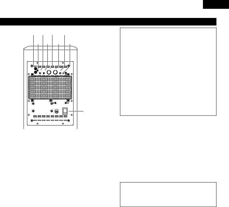
Active subwoofer (DSW-3L) rear panel
z c b m x v n ,
LINE IN |
|
CROSSOVER(Hz) |
LEVEL |
|
|
|
PHASE |
LF DIRECT |
|
AUTO STANDBY |
|
LINE OUT |
REV. NORM. |
ON OFF |
|
ON |
OFF |
|
|
50 |
200 MIN |
MAX |
ON:GREEN |
|
|
|
|
|
STANDBY:RED |
|
POWER |
ON |
. |
OFF |
|
zLine input connector (LINE IN)
•Connect this to the AV amplifier’s pre-out connector (“SUBWOOFER”, “MONO OUT”, etc.) using the included connection cord (3-meter RCA pin cord).
xLine output connector (LINE OUT)
•The signal input to the line input connector is output as such from here in parallel.
•When using two active subwoofers, connect the other active subwoofer’s line input connector to this connector.
cPhase selector switch (PHASE)
•This switches the phase of the output signal with respect to the input signal.
•Normally use the subwoofer with this switch set at the “NORM.” position. If the continuity between the sound of the active subwoofer and the left and right speakers seems unnatural, try switching to the “REV.” position, and set the switch to the position in which the sound is most natural.
vLF direct switch (LF DIRECT)
•When using the active subwoofer connected to a Dolby Digitalor dts-compatible AV amplifier, if this function is turned on the signals bypass the active subwoofer’s crossover and volume adjustment circuits, resulting in purer, higher quality
sound. Note that when this is done the crossover adjustment control (b) and volume adjustment control (n) will no longer function.
bCrossover adjustment control (CROSSOVER)
•This control only functions when the LF DIRECT switch (v) is set to the “OFF” position.
•This control sets the upper limit of the frequencies reproduced by the active subwoofer.
•Setting criteria
50Hz : For left/right speakers with diameters of 20 cm or greater
100Hz : For left/right speakers with diameters between 10 and 25 cm
200Hz : For left/right speakers with diameters of 12 cm or less
•When using a Dolby Digitalor dts-compatible AV amplifier, we recommend turning the LF DIRECT switch (v) to the “ON” position and not using this function.

 “Dolby” is a trademark of the Dolby Laboratories Licensing Corporation.

 “dts” is a trademark of Digital Theater Systems.
ENGLISH
About the AV amplifier’s crossover frequency selection
The crossover frequency of the satellite speaker/center speaker and the active subwoofer (the boundary between the frequency range produced by the active subwoofer and the other speakers) is set on the connected AV amplifier, and is usually fixed at between 80 and 120 kHz.
With some amplifiers, however, including the Denon ADVM51, this frequency can be selected. When using this type of amplifier, the crossover frequency can be selected to suit your tastes.
When using the DSW-3L active subwoofer with this type of amplifier, a richer sound can be achieved by setting the crossover frequency to around 150 Hz. Adjust the crossover frequency to suit your tastes. For instructions on switching, refer to your amplifier’s operating instructions.
When connecting to a Dolby Digitalor dts-compatible AV amplifier, whether one on which the crossover frequency is fixed or one on which it can be adjusted, we recommend setting the LF DIRECT switch of the active subwoofer (DSW3L) to the “ON” position.
nVolume adjustment control (LEVEL)
•This control only functions when the LF DIRECT switch (v) is set to the “OFF” position.
•Use this control to adjust the volume of the active subwoofer.
•When turned clockwise (  ) from the center position, the volume of the active subwoofer increases, and when turned counterclockwise (
  ), the volume decreases. Set to the desired position.
mAuto standby selector switch (AUTO STANDBY)
ON |
: The auto standby function is activated |
OFF |
: The auto standby function is deactivated |
Auto Standby Function
•The amplifier is automatically set to the standby mode if no signal is input for 5 to 11 minutes, thereby saving electricity.
The power turns on immediately when a signal is input.
,Status indicator
•The two-colored LED indicates the active subwoofer’s operating status, as follows:
Power “ON” ......................................................... |
Lights green |
Auto power off (standby mode)................................ |
Lights red |
Power “OFF”................................................................ |
LED off |
Protective circuit activated .................................... |
Flashing red |
.Power switch (POWER)
•The power turns on when this switch is set to the “ON” position.
•Several seconds are required for the set to begin operating. This is because the set includes a built-in muting circuit to prevent noise when the power switch is turned on and off.
•When set to the “OFF” position, the power turns off.
19
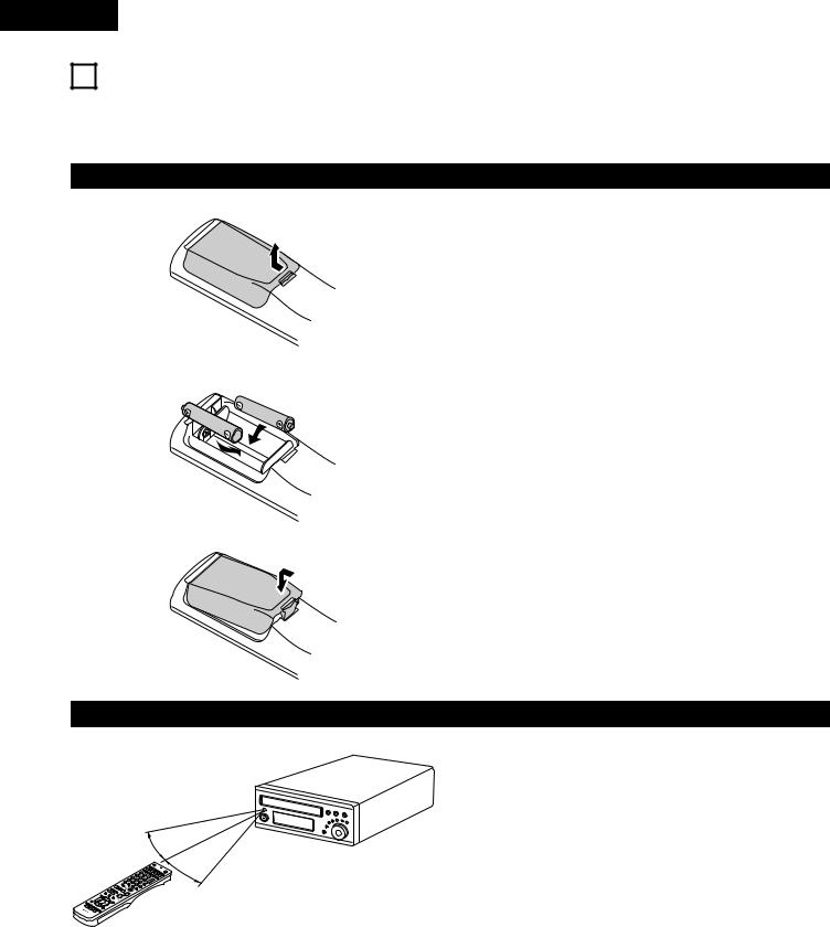
ENGLISH
9REMOTE CONTROL UNIT
•The included remote control unit (RC-966) can be used to operate not only this unit but other remote control compatible DENON components as well. In addition, the memory contains the control signals for other remote control units, so it can be used to operate non-DENON remote control compatible products.
(1) Inserting the batteries
q Remove the remote control unit’s rear cover.
wSet three R6P/AA batteries in the battery compartment in the indicated direction.
e Put the rear cover back on.
Notes on Batteries
•Use R6P/AA batteries in the remote control unit.
•The batteries should be replaced with new ones approximately once a year, though this depends on the frequency of usage.
•Even if less than a year has passed, replace the batteries with new ones if the set does not operate even when the remote control unit is operated nearby the set. (The included battery is only for verifying operation. Replace it with a new battery as soon as possible.)
•When inserting the batteries, be sure to do so in the proper direction, following the “≈” and “√” marks in the battery compartment.
•To prevent damage or leakage of battery fluid:
•Do not use a new battery together with an old one.
•Do not use two different types of batteries.
•Do not short-circuit, disassemble, heat or dispose of batteries in flames.
•Remove the batteries from the remote control unit when you do not plan to use it for an extended period of time.
•If the battery fluid should leak, carefully wipe the fluid off the inside of the battery compartment and insert new batteries.
•When replacing the batteries, have the new batteries ready and insert them as quickly as possible.
(2) Using the remote control unit
B
Approx. 7m / 22 feet
30°
|
1 |
- |
4 |
2 |
|
7 |
5 |
3 |
8 |
6 |
+ |
0 |
9 |
- |
+10 |
+ |
30° |
|
- |
|
+ |
|
|
-
- +
•Point the remote control unit at the remote sensor on the main unit as shown on the diagram.
•The remote control unit can be used from a straight distance of approximately 7 meters/22 feet from the main unit, but this distance will be shorter if there are obstacles in the way or if the remote control unit is not pointed directly at the remote sensor.
•The remote control unit can be operated at a horizontal angle of up to 30 degrees with respect to the remote sensor.
NOTES:
•It may be difficult to operate the remote control unit if the remote sensor is exposed to direct sunlight or strong artificial light.
•Do not press buttons on the main unit and remote control unit simultaneously. Doing so may result in malfunction.
•Neon signs or other devices emitting pulse-type noise nearby may result in malfunction, so keep the set as far away from such devices as possible.
20
ENGLISH
• The included remote control unit (RC-966) can be used to operate |
|
|
|
|
|
|
|
3 |
[1] MD recorder system buttons |
|
|||||
not only the ADV-M51 but also to perform system operations for |
|
||||||
(operated with mode switch 2 set to “MD”) |
|||||||
the D-M31 series and to operate other remote control compatible |
|||||||
DENON products. In addition, the remote control operation codes |
|
|
|
|
|
|
|
of other major brands of TVs and video decks are also stored in the |
|
|
OFF |
|
ON |
|
|
remote control unit, so the unit can be used to operate these TVs |
|
|
|
VCR |
|
|
|
|
|
|
SLEEP |
REC |
TITLE |
TIME |
|
|
|
|
NTSC/PAL |
||||
and video decks as well. |
|
|
SOURCE |
|
TV IN |
T V |
|
|
|
CLEAR |
A-B REPEAT |
SLIDE MODE |
ZOOM |
||
|
|
|
|
ENTER |
CHARAC. |
EDIT/MENU |
|
|
|
|
|
|
TV CH - |
TV CH + |
|
|
|
|
RDS |
PTY |
CT |
CD SRS RT |
|
|
|
|
PROG/DIRECT |
REPEAT |
RANDOM SEARCH MODE |
||
|
|
|
MODE |
MEMO |
BAND |
|
|
|
|
|
|
|
|
TUNING / |
|
|
|
|
DVD |
TUNER |
D.AUX |
TV VOL |
|
(3) Operating DENON audio components
•Turn on the power of all the components before operating them.
•Depending on the model and year of make of your component, some of the keys may not work.
1 |
2 |
3 |
+ |
MD/LINE-1 |
TAPE /LINE-2 |
|
- |
4 |
5 |
6 |
|
|
5CH STEREO |
AUTO DECODE |
TUNER |
7 |
8 |
9 |
+ |
DIRECT |
STEREO |
VIRTUAL |
CH |
CALL |
0/10 |
+10 |
- |
|
|
|
|
|
TEST TONE INPUT MODE |
SURROUND |
FUNCTION |
|||
|
|
|
|
|
|
|
|
|
TUNER TV / VCR |
|
|
|
|
|
|
A / V |
|
|
DVD |
IN/SURR |
|
|
OFF |
|
ON |
|
|
|
|
|
|
|
|
|
VCR |
|
|
|
|
|
|
|
|
|
SLEEP |
REC |
TITLE |
TIME |
|
|
|
|
|
SURROUND |
|
NTSC/PAL |
CH SELECT |
|
|
|
|
||||
|
|
|
|
|
|
|
|
|
PARAMETER |
|
|
SOURCE |
|
TV IN |
T V |
|
|
|
|
|
|
|
CLEAR |
ENTER |
CHARAC. |
EDIT/MENU |
|
|
|
|
|
|
|
A-B REPEAT |
SLIDE MODE |
ZOOM |
|
|
|
|
- VCR CH + |
||
|
|
|
TV CH - |
TV CH + |
|
|
|
|
||
|
RDS |
PTY |
CT |
CD SRS RT |
RETURN |
|
DISPLAY |
|
MENU |
TOP MENU |
|
PROG/DIRECT |
REPEAT |
RANDOM |
SEARCH MODE |
|
|
||||
|
MODE |
MEMO |
BAND |
|
|
|
|
|
|
|
3 |
|
|
|
TUNING / |
|
ANGLE |
AUDIO |
SUB TITLE |
||
DVD |
TUNER |
D.AUX |
TV VOL |
|
||||||
1 |
2 |
3 |
+ |
|
|
|
|
|
|
|
|
MD/LINE-1 |
TAPE /LINE-2 |
|
- |
|
|
|
|
|
|
|
4 |
5 |
6 |
|
|
RC-966 |
|
|||
|
|
|
|
|
|
|
||||
|
|
5CH STEREO |
AUTO DECODE |
TUNER |
|
|
|
|
|
|
|
7 |
8 |
9 |
+ |
|
|
|
|
|
|
|
DIRECT |
STEREO |
VIRTUAL |
CH |
|
|
|
|
|
|
|
CALL |
|
0/10 |
+10 |
- |
|
|
|
TEST TONE |
INPUT MODE |
SURROUND |
FUNCTION |
|
||
1 |
|
|
|
TUNER TV / VCR |
2 |
||
A / V |
|
|
DVD |
|
IN/SURR. |
||
|
SYSTEM |
MD |
CDR |
TAPE IN/SURR. |
|||
|
1 |
|
|
2 |
|
+ |
|
|
DVD |
|
|
|
|
|
|
|
8 |
|
9 |
|
|
|
|
|
6 |
|
7 |
|
- |
|
|
|
|
|
STATUS |
|
|
|
|
|
3 |
|
|
|
MUTING |
|
|
|
SETUP |
|
|
|
|
TONE /SDB |
|
|
|
|
ENTER |
|
|
|
|
|
CH SELECT |
|
|
|
|
SURROUND |
|
|
|
|
|
|
PARAMETER |
|
|
|
|
|
|
- VCR CH + |
|
||
3 |
RETURN |
|
DISPLAY |
MENU |
TOP MENU |
|
|
ANGLE |
AUDIO |
SUB TITLE |
|
||||
|
|
|
RC-966 |
|
|
|
|
1 |
Set mode switch 1 to the “SYSTEM” position. |
|||
|
||||
|
(Blue print) |
|||
|
A / V |
|
|
|
|
|
|||
|
|
|
SYSTEM |
|
|
|
|
||
|
|
|
||
TIME |
: Disc time display |
TITLE |
: Name display |
REC |
: Recording (multi-recording function with the DMD- |
|
M31) |
SOURCE |
: MD power on/off |
EDIT/MENU |
: Edit mode selection |
CHARAC |
: Selection of characters when inputting names |
ENTER |
: Entering of edited values |
CD SRS |
: CD synchronized recording (DMD-M31 system |
|
function) |
CLEAR |
: Program clearing |
RANDOM |
: Random play on/off |
REPEAT |
: Repeat play setting |
PROG/DIRECT : Program/direct playback selection |
|
CALL |
: Program calling |
1~10, +10 |
: Track number selection |
8, 9 |
: Auto search (cueing) |
6, 7 |
: Manual search (fast-reverse and fast-forward) |
1 (/ 3) |
: Play (play/pause, auto power on and auto function |
|
selector with the DMD-M31) |
3: Pause
2: Stop
2 |
Set mode switch 2 to the position for the component to be |
|||
|
|
|||
|
|
operated (MD, CDR or TAPE). |
|
|
|
|
(Blue print) |
|
|
|
|
TUNER TV / VCR |
||
|
|
DVD |
IN/SURR. |
|
|
|
|
IN/SURR. |
|
|
|
|
|
|
|
|
MD |
||
|
|
CDR |
TAPE |
|
|
|
|
|
|
|
3 |
Operate the audio component. |
|
|
|
|
|
||
• For details, refer to the component’s operating instructions. 
 Operation may not be possible for some models.
21
ENGLISH
[2]CD recorder system buttons
(operated with mode switch 2 set to “CDR”)
|
OFF |
|
ON |
|
|
|
VCR |
|
|
|
SLEEP |
REC |
TITLE |
TIME |
|
NTSC/PAL |
|||
|
SOURCE |
|
TV IN |
T V |
|
CLEAR |
ENTER |
CHARAC. |
EDIT/MENU |
|
A-B REPEAT |
SLIDE MODE |
ZOOM |
|
|
|
|
TV CH - |
TV CH + |
|
PROG/DIRECT |
REPEAT |
RANDOM |
CD SRS |
|
SEARCH MODE |
|||
|
MODE |
MEMO |
BAND |
|
|
|
|
|
TUNING / |
|
DVD |
TUNER |
D.AUX |
TV VOL |
|
1 |
2 |
3 |
+ |
|
MD/LINE-1 |
TAPE /LINE-2 |
|
- |
|
4 |
5 |
6 |
|
|
|
5CH STEREO |
AUTO DECODE |
TUNER |
|
7 |
8 |
9 |
+ |
|
DIRECT |
STEREO |
VIRTUAL |
CH |
|
CALL |
0/10 |
+10 |
- |
|
TEST TONE |
INPUT MODE |
SURROUND |
FUNCTION |
|
|
|
TUNER TV / VCR |
|
|
CH SELECT |
|
|
SURROUND |
|
|
|
PARAMETER |
|
|
|
|
- VCR CH + |
|
|
RETURN |
DISPLAY |
MENU |
TOP MENU |
|
ANGLE AUDIO SUB TITLE |
|||
|
|
RC-936 |
|
|
TIME |
: Disc time display |
|
|
|
TITLE |
: Name display and selection of characters when |
|||
|
inputting names |
|
|
|
REC |
: Recording |
|
|
|
SOURCE |
: CD recorder power on/off |
|||
EDIT/MENU |
: Menu selection |
|
|
|
ENTER |
: Entering of menu items |
|||
CLEAR |
: Program clearing |
|
|
|
RANDOM |
: Random play on/off |
|
||
REPEAT |
: Repeat play setting |
|
||
PROG/DIRECT : Program/direct playback selection |
||||
CALL |
: Program calling |
|
|
|
1~10, +10 : Track number selection
8, 9 |
: Auto search (cueing) |
6, 7 |
: Manual search (fast-reverse and fast-forward) |
1 (/ 3) |
: Play (play/pause, auto power on and auto function |
|
selection with the CDR-M30) |
3: Pause
2: Stop
[3]Tape deck system button
(operated with mode switch 2 set to “TAPE”)
|
OFF |
|
ON |
|
|
|
VCR |
|
|
|
SLEEP |
REC |
TITLE |
TIME |
|
NTSC/PAL |
|||
|
SOURCE |
|
TV IN |
T V |
|
CLEAR |
ENTER |
CHARAC. |
EDIT/MENU |
|
A-B REPEAT |
SLIDE MODE |
ZOOM |
|
|
|
|
TV CH - |
TV CH + |
|
PROG/DIRECT |
REPEAT |
RANDOM |
CD SRS |
|
SEARCH MODE |
|||
|
MODE |
MEMO |
BAND |
|
|
|
|
|
TUNING / |
|
DVD |
TUNER |
D.AUX |
TV VOL |
|
1 |
2 |
3 |
+ |
|
CH SELECT |
|
|
SURROUND |
|
|
|
PARAMETER |
|
|
|
|
- VCR CH + |
|
|
RETURN |
DISPLAY |
MENU |
TOP MENU |
|
ANGLE AUDIO SUB TITLE |
|||
|
|
RC-936 |
|
|
REC |
: Recording |
|
|
|
CD SRS |
: CD synchronized recording (DRR-M31 system |
|||
|
function) |
|
|
|
6, 7 : Rewind and fast-forward
1: Forward direction play
0 TAPE |
: Reverse direction play (0 and 1: auto power on |
|
and auto function selection with the DRR-M31) |
|
|
22
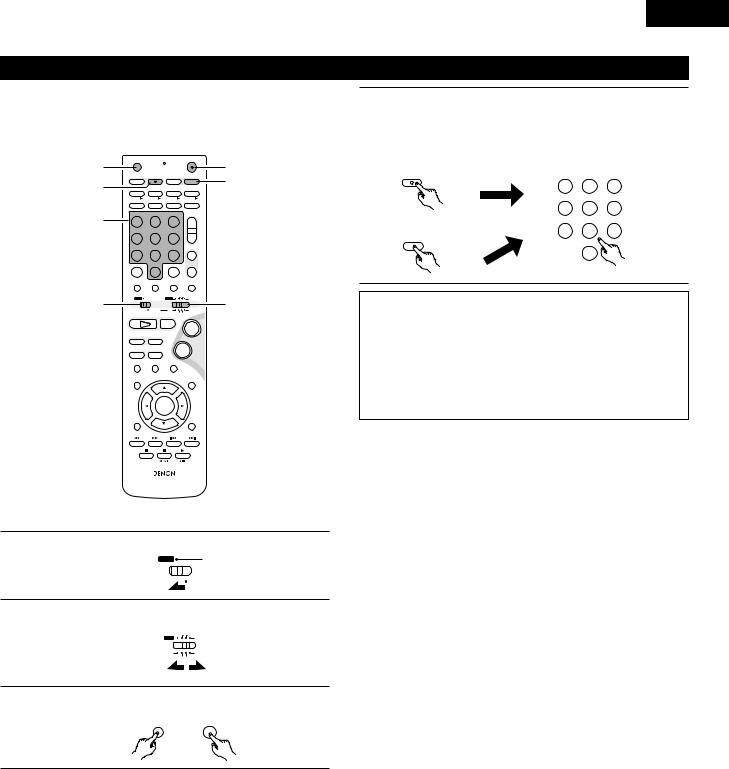
(4) TV and video deck preset memories
•Components of other brands can be operated with the included remote control unit by storing their codes in the preset memory. Note that depending on the model some operations may not be possible and some buttons may not operate properly.
3 |
OFF |
|
ON |
3 |
|
|
VCR |
|
|
||
SLEEP |
REC |
TITLE |
TIME |
||
NTSC/PAL |
4 |
||||
4 |
SOURCE |
|
TV IN |
T V |
|
CLEAR |
ENTER |
CHARAC. |
EDIT/MENU |
||
A-B REPEAT |
SLIDE MODE |
ZOOM |
|||
|
|
TV CH - |
TV CH + |
|
|
|
RDS |
PTY |
CT |
CD SRS RT |
|
|
PROG/DIRECT |
REPEAT |
RANDOM |
SEARCH MODE |
|
|
MODE |
MEMO |
BAND |
|
|
4 |
|
|
|
TUNING / |
|
DVD |
TUNER |
D.AUX |
TV VOL |
|
|
1 |
2 |
3 |
+ |
|
|
|
MD/LINE-1 |
TAPE /LINE-2 |
|
- |
|
|
4 |
5 |
6 |
|
|
|
|
5CH STEREO |
AUTO DECODE |
TUNER |
|
|
7 |
8 |
9 |
+ |
|
|
DIRECT |
STEREO |
VIRTUAL |
CH |
|
|
CALL |
0/10 |
+10 |
- |
|
|
TEST TONE |
INPUT MODE |
SURROUND |
FUNCTION |
|
1 |
|
|
TUNER TV / VCR |
2 |
|
A / V |
|
DVD |
IN/SURR. |
||
|
SYSTEM |
MD CDR TAPE IN/SURR. |
|||
|
1 |
|
2 |
+ |
|
|
DVD |
|
|
|
|
|
8 |
9 |
|
|
|
|
6 |
7 |
- |
|
|
|
|
STATUS |
|
|
|
|
3 |
|
MUTING |
|
|
|
SETUP |
|
|
TONE /SDB |
|
ENTER
CH SELECT |
|
|
SURROUND |
|
|
PARAMETER |
|
|
|
- VCR CH + |
|
RETURN |
DISPLAY |
MENU |
TOP MENU |
ANGLE |
AUDIO |
|
SUB TITLE |
RC-966
2 Not set upon shipment from the factory.
1 |
Set mode switch 1 to the “A/V” position. |
||
|
|||
|
|
A / V |
|
|
|
|
SYSTEM |
2 |
Set mode switch 2 to the “TV/VCR” position. |
||
|
TUNER TV / VCR |
||
|
|
DVD |
IN/SURR. |
|
|
MD |
IN/SURR. |
|
|
|
CDR TAPE |
3 |
Press the power ON button and the OFF button simultaneously. |
||
|
|||
|
• |
The transmission LED (indicator) flashes. |
|
|
|
OFF |
ON |
ENGLISH
4 |
Press the TV button to preset a TV, the VCR button to preset |
|||
|
||||
|
a video deck, then input the 3-digit number corresponding to |
|||
|
the brand of the component whose signals are to be stored in |
|||
|
the preset memory (refer to the tables of remote control |
|||
|
codes on pages 24 to 27). |
|
|
|
|
TIME |
DVD |
TUNER |
D.AUX |
|
T |
|
|
|
|
|
5CH STEREO |
AUTO DECODE |
|
|
VCR |
7 |
8 |
9 |
|
REC |
|
|
|
|
NTSC/PAL |
|
STEREO |
|
|
|
|
|
|
|
|
|
0/10 |
|
NOTES: |
|
|
|
|
• |
When buttons are |
setting the preset memory, |
||
|
their signals are sent |
remote control transmitter, so |
||
|
cover the remote |
when |
setting the preset |
|
|
memory to prevent |
. |
|
|
• Depending on the model |
make, some of the remote control |
|||
|
codes for the brands |
tables may not operate properly. |
||
• |
For some brands there |
types of remote control codes. If |
||
|
an operation does not |
to one of the other codes. |
||
23

ENGLISH
Combinations of preset codes for different brands
TV
Admiral |
045, 121 |
|
|
Adventura |
122 |
|
|
Aiko |
054 |
|
|
Akai |
016, 027, 046 |
|
|
Alleron |
062 |
|
|
A-Mark |
007 |
|
|
Amtron |
061 |
|
|
Anam |
006, 007, 036 |
|
|
Anam National |
061, 147 |
|
|
AOC |
003, 007, 033, 038, 039, 047, 048, 049, 133 |
|
|
Archer |
007 |
|
|
Audiovox |
007, 061 |
|
|
Bauer |
155 |
|
|
Belcor |
047 |
|
|
Bell & Howell |
045, 118 |
|
|
Bradford |
061 |
|
|
Brockwood |
003, 047 |
|
|
Candle |
003, 030, 031, 032, 038, 047, 049, 050, 122 |
|
|
Capehart |
003 |
|
|
Celebrity |
046 |
|
|
Circuit City |
003 |
|
|
Citizen |
029, 030, 031, 032, 034, 038, 047, 049, 050, 054, |
|
061, 095, 122, 123 |
|
|
Concerto |
031, 047, 049 |
|
|
Colortyme |
003, 047, 049, 135 |
|
|
Contec |
013, 051, 052, 061 |
|
|
Cony |
051, 052, 061 |
|
|
Craig |
004, 061 |
|
|
Crown |
029 |
|
|
Curtis Mathes |
029, 034, 038, 044, 047, 049, 053, 095, 118 |
|
|
Daewoo |
027, 029, 039, 048, 049, 054, 055, 106, 107, 137 |
|
|
Daytron |
003, 049 |
|
|
Dimensia |
044 |
|
|
Dixi |
007, 015, 027 |
|
|
Electroband |
046 |
|
|
Electrohome |
029, 056, 057, 058, 147 |
Elta |
027 |
|
|
Emerson |
029, 051, 059, 060, 061, 062, 118, 123, 124, 139, 148 |
|
|
Envision |
038 |
|
|
Etron |
027 |
|
|
Fisher |
014, 021, 063, 064, 065, 118 |
|
|
Formenti |
155 |
|
|
Fortress |
012 |
|
|
Fujitsu |
004, 062 |
|
|
Funai |
004, 062 |
Futuretech |
004 |
|
|
GE |
020, 036, 037, 040, 044, 058, 066, 088, 119, 120, |
|
125, 147 |
Goldstar |
015, 029, 031, 039, 048, 051, 056, 057, 067, |
|
068, 069, 116, 165 |
|
|
Grundy |
062 |
Hitachi |
029, 031, 051, 052, 070, 111, 112, 113, 124, 134 |
|
|
Hitachi Pay TV |
151 |
Infinity |
017, 071 |
|
|
Janeil |
122 |
JBL |
017, 071 |
|
|
JC Penny |
020, 034, 039, 040, 041, 044, 048, 050,058, 066, |
|
069, 076, 088, 090, 095, 125, 136, 159 |
JCB |
046 |
|
|
JVC |
019, 051, 052, 072, 073, 091, 117, 126 |
Kawasho |
018, 046 |
|
|
Kenwood |
038, 056, 057 |
Kloss |
010, 032 |
|
|
Kloss Novabeam |
005, 122, 127, 131 |
KTV |
074, 123 |
|
|
Loewe |
071 |
Logik |
144 |
|
|
Luxman |
031 |
LXI |
008, 014, 017, 024, 040, 044, 063, 071, 075, 076, |
|
077, 118, 125 |
|
|
Magnavox |
005, 010, 017, 030, 033, 038, 050, 056, 071, 078, |
|
079, 085, 089, 108, 109, 110, 127, 131, 132, 145 |
Marantz |
015, 017, 071, 080 |
Matsui |
027 |
|
|
Memorex |
014, 027, 045, 083, 118, 144 |
Metz |
160, 161, 162, 163, 164 |
|
|
MGA |
001, 039, 048, 056, 057, 058, 065 081, 083 |
Midland |
125 |
|
|
Minutz |
066 |
Mitsubishi |
001, 016, 039, 048, 056, 057, 058, 065, 081, 082, |
|
083, 105 |
|
|
Montgomery Ward |
011, 020, 144, 145, 146 |
Motorola |
121, 147 |
|
|
MTC |
031, 034, 039, 048, 095 |
NAD |
008, 075, 076, 128 |
|
|
National |
002, 036, 061, 147 |
|
|
24

ENGLISH
National Quenties |
002 |
NEC |
031, 038, 039, 048, 057, 084, 086, 135, 147 |
Nikko |
054 |
|
|
NTC |
054 |
Optimus |
128 |
|
|
Optonica |
011, 012, 093, 121 |
Orion |
004, 139 |
|
|
Panasonic |
002, 009, 017, 036, 037, 071, 141, 143, 147 |
Philco |
005, 010, 030, 050, 051, 056, 079, 085, 127, 131, |
|
132, 145, 147 |
|
|
Philips |
005, 015, 017, 050, 051, 056, 078, 087, 088, 089, |
|
131, 132, 147 |
Pioneer |
124, 128, 142 |
|
|
Portland |
054 |
Price Club |
095 |
|
|
Proscan |
040, 044, 125 |
Proton |
035, 051, 092, 129 |
|
|
Pulsar |
042 |
Quasar |
036, 037, 074, 141 |
|
|
Radio Shack |
011, 044, 063, 093, 118 |
RCA |
040, 044, 125, 130, 137, 151, 152 |
|
|
Realistic |
014, 063, 093, 118 |
Saisho |
027 |
|
|
Samsung |
003, 015, 034, 053, 055, 057, 094, 095, 136, 153 |
Sansui |
139 |
|
|
Sanyo |
013, 014, 021, 022, 063, 064, 081, 096 |
SBR |
015 |
|
|
Schneider |
015 |
Scott |
062 |
|
|
Sears |
008, 014, 021, 022, 023, 024, 025, 040, 052, 057, |
|
062, 063, 064, 065, 073, 075, 076, |
|
097, 098, 125, 159 |
|
|
Sharp |
011, 012, 013, 026, 093, 099, 100, 104, 121 |
|
|
Siemens |
013 |
Signature |
045, 144 |
|
|
Simpson |
050 |
Sony |
043, 046, 138, 146, 150 |
|
|
Soundesign |
030, 050, 062 |
|
|
Spectricon |
007, 033 |
|
|
Squareview |
004 |
Supre-Macy |
032, 122 |
|
|
Supreme |
046 |
Sylvania |
005, 010, 017, 030, 078, 079, 085, 089, 101, 127, |
|
131, 132, 145, 155 |
|
|
Symphonic |
004, 148 |
Tandy |
012, 121 |
|
|
Tatung |
036, 124 |
Technics |
037 |
|
|
Teknika |
001, 030, 032, 034, 052, 054, 078, 083, 095, 144, |
|
156, 157 |
Tera |
035, 129 |
|
|
Toshiba |
008, 014, 034, 063, 075, 076, 095, 097, 136, 158, |
|
159 |
Universal |
020, 066, 088 |
|
|
Victor |
019, 073, 126 |
Video Concepts |
016 |
|
|
Viking |
032, 122 |
Wards |
005, 045, 066, 078, 085, 088, 089, 093, 102, 103, |
|
131, 132, 148 |
|
|
Zenith |
042, 114, 115, 140, 144, 149 |
Zonda |
007 |
25

ENGLISH
VCR
Admiral |
081 |
|
|
Aiko |
095 |
|
|
Aiwa |
009 |
|
|
Akai |
026, 027, 070, 072, 082, 083, 084 |
|
|
Alba |
055 |
|
|
Amstrad |
009 |
|
|
ASA |
042 |
|
|
Asha |
087 |
|
|
Audio Dynamic |
005, 085 |
|
|
Audiovox |
088 |
|
|
Beaumark |
087 |
|
|
Broksonic |
086, 093 |
|
|
Calix |
088 |
|
|
Candle |
006, 087, 088, 089, 090 |
|
|
Canon |
049, 057 |
|
|
Capehart |
025, 055, 056, 071 |
|
|
Carver |
015 |
|
|
CCE |
095 |
|
|
Citizen |
006, 007, 087, 088, 089, 090, 095 |
|
|
Craig |
007, 087, 088, 091, 115 |
|
|
Curtis Mathes |
006, 049, 073, 080, 087, 090, 092 |
|
|
Cybernex |
087 |
|
|
Daewoo |
025, 055, 059, 074, 089, 093, 095, 096 |
|
|
Daytron |
025, 055 |
|
|
DBX |
005, 085 |
|
|
Dumont |
053 |
|
|
Dynatech |
009 |
|
|
Electrohome |
001, 088, 097 |
|
|
Electrophonic |
088 |
|
|
Emerson |
001, 009, 017, 027, 086, 088, 089, 092, 093, 097, |
|
100, 101, 102, 103, 104, 117 |
|
|
Fisher |
009, 028, 031, 053, 054, 091, 098, 099, 115 |
GE |
007, 011, 049, 050, 051, 052, 073, 080, 087 |
|
|
Go Video |
047, 048 |
|
|
Goldstar |
006, 012, 062, 088, 129 |
|
|
Gradiente |
094 |
|
|
Grundig |
042 |
|
|
Harley Davidson |
094 |
Harman Kardon |
040, 062 |
Hi-Q |
091 |
|
|
Hitachi |
009, 013, 023, 026, 058, 108, 109, 110, 111 |
JC Penny |
004, 005, 007, 023, 028, 049, 062, |
|
085, 087, 088 |
|
|
Jensen |
013, 026 |
|
|
JVC |
004, 005, 006, 026, 029, 043, 044, 045, 046, 085 |
|
|
Kenwood |
004, 005, 006, 026, 029, 033, 045, 085, 090 |
Kodak |
088 |
|
|
Lloyd |
009, 094 |
LXI |
088 |
|
|
Magnavox |
015, 016, 042, 049, 063, 106 |
Magnin |
087 |
|
|
Marantz |
004, 005, 006, 015, 042, 049, 085, 090 |
Marta |
088 |
|
|
MEI |
049 |
Memorex |
009, 033, 049, 053, 060, 081, 087, 088, 091, 094, |
|
115 |
|
|
Metz |
123, 124, 125, 126, 127, 128 |
MGA |
001, 017, 027, 041, 097 |
|
|
MGN Technology |
087 |
Midland |
011 |
|
|
Minolta |
013, 023 |
Mitsubishi |
001, 003, 008, 013, 014, 017, 027, 029, 039, 040, |
|
041, 045, 097 |
|
|
Motorola |
081 |
Montgomery Ward |
001, 002, 007, 009, 049, 063, 081, 115, 117 |
|
|
MTC |
009, 087, 094 |
Multitech |
007, 009, 011, 087, 090, 094 |
|
|
NAD |
038 |
NEC |
004, 005, 006, 018, 026, 029, 045, 061, 062, 085 |
|
|
Nikko |
088 |
Noblex |
087 |
|
|
Optimus |
081, 088 |
Optonica |
021 |
|
|
Panasonic |
024, 049, 064, 066, 067, 068, 069, 107 |
Perdio |
009 |
|
|
Pentax |
006, 013, 023, 058, 090 |
Philco |
015, 016, 049 |
|
|
Philips |
015, 021, 042, 049, 105 |
Pilot |
088 |
|
|
Pioneer |
005, 013, 029, 036, 037, 038, 045, 085 |
Portland |
025, 055, 090 |
|
|
Proscan |
063, 080 |
Pulsar |
060 |
|
|
Quartz |
033 |
Quasar |
034, 035, 049 |
|
|
Radio Shack |
001, 002, 021, 081, 087, 088, 091, 094, 097, 098, |
|
115 |
Radix |
088 |
26

ENGLISH
|
|
|
|
|
Randex |
088 |
|
Symphonic |
009, 094 |
RCA |
007, 013, 019, 023, 058, 063, 064, 065, 073, 080, |
|
Tandy |
009 |
|
082, 087 |
|
|
|
|
|
Tashiko |
009, 088 |
|
|
|
|
|
|
Realistic |
009, 021, 031, 033, 049, 053, 081, 087, 088, 091, |
|
Tatung |
004, 026, 030 |
|
094, 097, 098 |
|
|
|
|
|
Teac |
004, 009, 026, 094 |
|
Ricoh |
055 |
|
Technics |
024, 049 |
|
|
|
|
|
Salora |
033, 041 |
|
Teknika |
009, 010, 022, 049, 088, 094 |
Samsung |
007, 011, 051, 059, 070, 083, 087, 089, 113 |
|
TMK |
087, 092 |
|
|
|
|
|
Sanky |
081 |
|
Toshiba |
013, 017, 020, 041, 059, 089, 098, 099, 117 |
Sansui |
005, 026, 029, 045, 061, 085, 114 |
|
Totevision |
007, 087, 088 |
|
|
|
|
|
Sanyo |
032, 033, 053, 087, 091, 115, 116 |
|
Unirech |
087 |
SBR |
042 |
|
Vecrtor Research |
005, 062, 085, 089, 090 |
|
|
|
|
|
Scott |
017, 020, 086, 089, 093, 117 |
|
Victor |
005, 045, 046, 085 |
Sears |
013, 023, 028, 031, 033, 053, 054, 088, 091, 098, |
|
Video Concepts |
005, 027, 085, 089, 090 |
|
099, 115 |
|
|
|
|
|
Videosonic |
007, 087 |
|
|
|
|
|
|
Sentra |
055 |
|
Wards |
013, 021, 023, 087, 088, 089, 091, 094, 097, 118, |
Sharp |
001, 002, 021, 097 |
|
|
119, 120 |
|
|
|
|
|
Shogun |
087 |
|
XR-1000 |
094 |
Sony |
075, 076, 077, 078, 079, 121, 122 |
|
Yamaha |
004, 005, 006, 026, 062, 085 |
|
|
|
|
|
STS |
023 |
|
Zenith |
060, 078, 079 |
Sylvania |
009, 015, 016, 017, 041, 049, 094 |
|
|
|
|
|
|
|
|
27
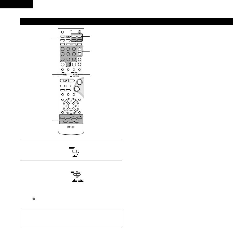
ENGLISH
(5) Operating the TV/video deck after storing its remote control signals in the preset memory
|
OFF |
|
|
|
ON |
|
|
|
|
|
|
VCR |
|
|
|
|
|
|
SLEEP |
|
REC |
TITLE |
TIME |
3-q |
||
|
NTSC/PAL |
|||||||
3-w |
SOURCE |
|
|
TV IN |
T |
V |
||
CLEAR |
|
ENTER |
CHARAC. |
EDIT/MENU |
||||
A-B REPEAT |
SLIDE MODE |
ZOOM |
||||||
|
|
|
TV CH - |
TV CH + |
|
|||
|
RDS |
|
PTY |
|
CT |
CD SRS RT |
|
|
|
PROG/DIRECT |
|
REPEAT |
RANDOM |
SEARCH MODE |
|
||
|
MODE |
|
MEMO |
BAND |
|
|
|
|
|
|
|
|
|
|
TUNING / |
|
|
|
DVD |
|
TUNER |
D.AUX |
TV VOL |
|
||
|
1 |
|
2 |
3 |
+ |
3-q |
||
|
4 |
|
5 |
6 |
- |
|||
|
MD/LINE-1 |
TAPE /LINE-2 |
|
|
|
|
|
|
|
|
5CH STEREO |
AUTO DECODE |
TUNER |
|
|||
|
7 |
|
8 |
9 |
+ |
|
||
|
DIRECT |
|
STEREO |
VIRTUAL |
|
CH |
|
|
|
CALL |
|
0/10 |
+10 |
- |
|
||
|
TEST TONE |
INPUT MODE |
SURROUND |
FUNCTION |
|
|||
1 |
|
|
|
TUNER TV / VCR |
|
2 |
||
A / V |
|
|
DVD |
|
IN/SURR. |
|||
|
SYSTEM |
MD |
CDR TAPE IN/SURR. |
|||||
|
1 |
|
|
2 |
|
+ |
|
|
|
DVD |
|
|
|
|
|
||
|
8 |
|
9 |
|
|
|
|
|
|
6 |
|
7 |
|
- |
|
|
|
|
|
|
STATUS |
|
|
|
|
|
|
3 |
|
|
|
MUTING |
|
|
|
|
SETUP |
|
|
|
|
TONE /SDB |
|
|
|
|
|
ENTER |
|
|
|
|
|
|
CH SELECT |
|
|
|
|
SURROUND |
|
|
|
|
|
|
|
PARAMETER |
|
||
|
|
|
|
- VCR CH |
+ |
|
||
3-w |
RETURN |
|
DISPLAY |
MENU |
TOP MENU |
|
||
ANGLE |
AUDIO |
SUB TITLE |
|
|
||||
|
|
|
RC-966 |
|
|
|
|
|
1 |
Set mode switch 1 to the “A/V” position. |
||
|
|||
|
A / V |
|
|
|
|
||
|
|
SYSTEM |
|
|
|
||
|
|
||
3 |
Monitor TV (TV) and video deck (VCR) system buttons |
|
|
||
|
q TV system buttons |
|
|
TV |
: Power on/off |
|
0~9 |
: Channel numbers |
|
TV IN |
: TV input switching |
|
TV VOL +, – |
: Volume up/down |
|
TV CH +, – |
: Channel switching |
|
w Video deck system buttons |
|
|
VCR |
: Power on/off |
|
VCR CH +, – |
: Channel switching |
|
6, 7 |
: Manual search (fast-forward and fast-backward) |
|
1 |
: Play |
|
3 |
: Pause |
|
2 |
: Stop |
|
|
|
2 |
Set mode switch 2 to the “TV/VCR” position. |
||||
|
TUNER TV / VCR |
||||
|
|
|
DVD |
|
IN/SURR. |
|
|
|
MD |
|
IN/SURR. |
|
|
|
|
||
|
|
|
|
||
|
|
|
CDR |
TAPE |
|
|
|
|
|
|
|
3 |
Operate the video component. |
|
|
||
|
|
|
|
||
|
|
• |
For details, refer to the component’s operating instructions. |
||
|
|
|
It may not be possible to operate some models. |
||
|
|
|
|
|
|
NOTE:
•The TV’s “TV (POWER)” and “TV IN” buttons can be operated as long as mode switch 1 is set to the “A/V” position, regardless of the position of mode switch 2.
28
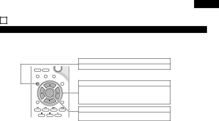
ENGLISH
10SETTING UP THE SYSTEM
(1) System setup items
•Once all connections with other AV components have been completed as described in “CONNECTIONS” (see pages 8 to 14), make the various settings described below on the monitor screen using the ADV-M51’s on-screen display function.
•Use the following buttons to set up the system:
6 |
7 |
|
- |
|
|
STATUS |
|
|
|
3 |
|
|
MUTING |
|
SETUP |
|
|
TONE /SDB |
|
|
ENTER |
|
|
|
CH SELECT |
|
|
|
SURROUND |
|
|
|
PARAMETER |
|
|
|
- VCR CH |
+ |
|
RETURN |
DISPLAY |
MENU |
TOP MENU |
|
ANGLE |
AUDIO |
|
SUB TITLE |
|
SYSTEM SETUP button
Press this to display the system setup menu.
CURSOR buttons
1 and 0:Use these to move the cursors (1 and 0) to the left and right on the screen.
•and ª: Use these to move the cursors (• and ª) to the up and down on the screen.
ENTER button
Press this to switch the display.
Also use this button to complete the setting.
System setup items and default values (set upon shipment from the factory)
|
|
Setup |
|
|
Default settings |
|
|
|
|
|
|
|
|
|
|
|
|
|
Quick set up |
Set the screen size and the speaker system. |
TV Aspect |
|
|
|
Speaker |
|
|
|
|
|
|
|
|
||
|
4:3 PS |
|
|
2CH Virtual & SW |
||||
|
|
|
|
|
||||
|
|
|
|
|
|
|
|
|
|
|
Input the combination of speakers in your system and |
Front Sp. |
|
|
|
Sub Woofer |
|
|
|
their corresponding sizes (SMALL for regular speakers, |
|
|
|
|
|
|
|
|
|
|
|
|
|
|
|
|
Speaker Configuration |
LARGE for full-size, full-range) to automatically set the |
SMALL |
|
|
|
YES |
|
|
|
composition of the signals output from the speakers and the |
|
|
|
|
|
|
|
|
|
|
|
|
|
|
|
|
|
frequency response. |
|
|
Sw Freq. = 150 Hz |
|
|
|
|
|
|
|
|
|
|
|
|
|
Delay Time |
This parameter is for optimizing the timing with which the |
Front |
|
|
|
Subwoofer |
|
|
audio signals are produced from the speakers and subwoofer |
|
|
|
|
|
|
|
|
|
|
|
|
|
|
||
|
|
according to the listening position. |
2.7m (9ft) |
|
|
|
2.7m (9ft) |
|
Setup |
|
|
|
|
|
|
|
|
Channel Level |
At the listening position, listen to the test tones output |
Front L |
|
Front R |
|
Sub Woofer |
||
from the different speakers and set so that the playback |
|
|
|
|
|
|
||
0 dB |
|
0 dB |
|
0 dB |
||||
System |
|
level from the different speakers is equal. |
|
|
||||
|
|
|
|
|
|
|
|
|
AV1 VIDEO OUTPUT |
To select whether composite video signals or S video signals |
|
|
VIDEO OUTPUT |
|
|
||
|
|
|
|
|
|
|
||
|
or RGB signals will be output from the AV1 SCART terminals. |
|
|
VIDEO |
|
|
||
|
|
|
|
|
|
|||
|
|
|
|
|
|
|
||
|
|
|
|
|
|
|
|
|
|
DVD auto power off setting |
The power automatically switches to standby if no |
|
|
|
|
|
|
|
operation is performed for 30 minutes while in the stop |
power does not turn off automatically |
||||||
|
|
mode with the function set to DVD. |
|
|
|
|
|
|
|
|
|
|
|
|
|
|
|
|
Function Assignment |
Set the LINE-1 and LINE-2 function names and turn the |
LINE-1 |
|
LINE-2 |
|
REC OUT |
|
|
|
|
|
|
|
|
||
|
analog recording output (REC OUT) on or off. |
MD |
|
TAPE |
|
ON |
||
|
|
|
|
|||||
|
|
|
|
|
||||
|
|
|
|
|
|
|
|
|
|
Disc Setup |
Set the audio language, subtitle language and disc menu |
Dialog |
|
Subtitle |
|
Disc Menu |
|
|
|
|
|
|
|
|
||
|
language for when playing discs. |
English |
|
English |
|
English |
||
|
|
|
|
|||||
|
|
|
|
|
||||
|
|
|
|
|
|
|
|
|
|
OSD Setup |
Set the wallpaper for the setup and operation screens. |
|
|
Wall Paper |
|
|
|
|
|
|
|
|
|
|
||
|
|
|
Blue |
|
|
|||
|
|
|
|
|
|
|
||
|
|
|
|
|
|
|
||
|
Video Setup |
Set the screen size and video system for the TV being used. |
TV Aspect |
|
TV Type |
|
Black level |
|
Setup |
|
|
|
|
|
|
||
4 : 3 PS |
|
PAL |
|
DARKER |
||||
|
|
|
|
|||||
|
|
|
|
|
|
|
|
|
DVD |
Audio Setup |
Set the digital audio signal format and the linear PCM |
Digital Out |
|
|
|
LPCM Select |
|
|
|
|
|
|
|
|||
|
sampling frequency and bit conversion. |
Normal |
|
|
|
OFF |
||
|
|
|
|
|
||||
|
|
|
|
|
|
|||
|
|
|
|
|
|
|
|
|
|
Ratings |
Make the playback restriction setting for DVDs with |
Rating Level |
|
|
Pass Word Change |
||
|
restricted viewing and set the password required for |
|
|
|
|
|
|
|
|
|
|
|
|
|
|
||
|
|
changing the setting. |
No Limit |
|
|
|
0000 (Default) |
|
|
|
|
|
|
|
|
|
|
|
Other Setup |
Make the closed caption setting for DVDs. (A commercially |
Closed Caption |
|
|
|
Slide Show |
|
|
|
|
|
|
|
|
||
|
available decoder is required to display the closed captions.) |
OFF |
|
|
|
5SEC |
||
|
|
|
|
|
||||
|
|
|
|
|
|
|||
|
|
|
|
|
|
|
|
|
29
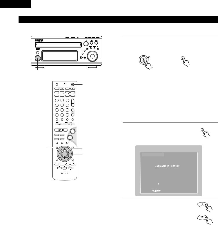
ENGLISH
(2) Quick setup procedure
•Refer to “Connections” (pages 8 to 14) and check that all the connections are correct.
Radio |
MP |
WMA |
|
DVD SURROUND RECEIVER ADV-M51 |
|
SURROUND SELECT |
|
|
PUSH-PARAM |
|
|
|
|
MENU SET |
BAND |
|
|
|
|
V I D E O |
|
TONE SDB |
VOLUME |
|
|
FUNCTION |
|
ON STANDBY
PHONES
Turn on the power.
1 • The power indicator (LED) lights green, the power turns on and the display lights.
ON / STANDBY
Green
ON
1
2,9
OFF |
|
ON |
|
|
VCR |
|
|
SLEEP |
REC |
TITLE |
TIME |
NTSC/PAL |
|||
SOURCE |
|
TV IN |
T V |
CLEAR |
ENTER |
CHARAC. |
EDIT/MENU |
A-B REPEAT |
SLIDE MODE |
ZOOM |
|
|
|
TV CH - |
TV CH + |
RDS |
PTY |
CT |
CD SRS RT |
PROG/DIRECT |
REPEAT |
RANDOM |
SEARCH MODE |
MODE |
MEMO |
BAND |
|
|
|
|
TUNING / |
DVD |
TUNER |
D.AUX |
TV VOL |
1 |
2 |
3 |
+ |
MD/LINE-1 |
TAPE /LINE-2 |
|
- |
4 |
5 |
6 |
|
|
5CH STEREO |
AUTO DECODE |
TUNER |
7 |
8 |
9 |
+ |
DIRECT |
STEREO |
VIRTUAL |
CH |
CALL |
0/10 |
+10 |
- |
TEST TONE |
INPUT MODE |
SURROUND |
FUNCTION |
|
|
TUNER TV / VCR |
|
A / V |
|
DVD |
IN/SURR. |
|
SYSTEM |
MD |
IN/SURR. |
|
|
CDR TAPE |
|
1 |
|
2 |
+ |
DVD |
|
|
|
8 |
9 |
|
|
|
|
- |
|
67
STATUS
3MUTING
SETUP TONE /SDB
ENTER
CH SELECT |
|
|
SURROUND |
|
|
PARAMETER |
|
|
|
- VCR CH + |
|
RETURN |
DISPLAY |
MENU |
TOP MENU |
ANGLE |
AUDIO |
|
SUB TITLE |
RC-966
1
4,6,8
3,5,7
Main unit |
Remote control unit |

 Several seconds are required from the time the power button is pressed until the power turns on. This is due to the built-in muting circuit that turns off (mutes) the sound when the power is turned on and off. The power indicator flashes green while the muting circuit is activated.

 Even when the power button has been pressed again and the power has been set to the standby mode, power is still supplied to some circuits. When leaving home or traveling, be sure to unplug the power cord from the power outlet. In the standby mode, the power indicator is lit red. The indicator is orange when the timer is set.
2 |
Press the SETUP button to display the |
SETUP |
setup screen. |
|
|
|
|
Remote control unit
SETUP MENU |
DENON |
QUICK |
SETUP |
SYSTEM SETUP |
|
DVD SETUP |
|
EXIT |
SETUP |
SELECT : |
DECISION : ENTER BUTTON |
3 |
Use the • and ª cursor buttons to |
|
|
|
select “Quick Setup”. |
|
• The selected item is displayed in |
|
yellow. |
Remote control unit
30
 Loading...