

Page 1
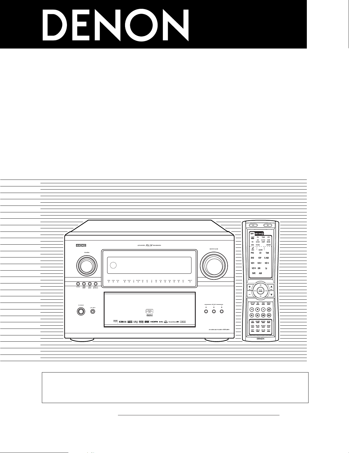
AV SURROUND RECEIVER
AVR-5805
OPERATING INSTRUCTIONS
RC-995
2
We greatly appreciate your purchase of the AVR-5805.
2
To be sure you take maximum advantage of all the features the AVR-5805 has to offer, read these instructions
carefully and use the set properly. Be sure to keep this manual for future reference should any questions or
problems arise.
“SERIAL NO.
PLEASE RECORD UNIT SERIAL NUMBER ATTACHED TO THE REAR OF THE
CABINET FOR FUTURE REFERENCE”
Page 2
2
2 SAFETY PRECAUTIONS
2 NOTE ON USE / OBSERVATIONS RELATIVES A L’UTILISATION
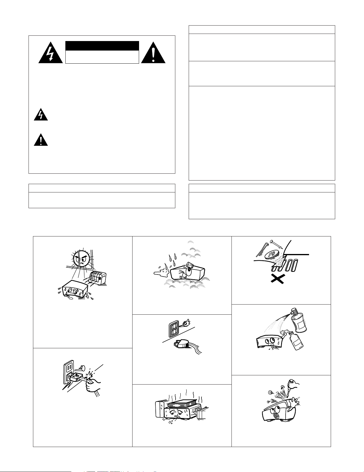
•Avoid high temperatures.
Allow for sufficient heat dispersion when
installed on a rack.
• Eviter des températures élevées.
Tenir compte d’une dispersion de chaleur
suffisante lors de l’installation sur une étagère.
• Handle the power cord carefully.
Hold the plug when unplugging the cord.
• Manipuler le cordon d’alimentation avec
précaution.
Tenir la prise lors du débranchement du
cordon.
• Keep the set free from moisture, water, and
dust.
•Protéger l’appareil contre l’humidité, l’eau et la
poussière.
• Unplug the power cord when not using the set
for long periods of time.
• Débrancher le cordon d’alimentation lorsque
l’appareil n’est pas utilisé pendant de longues
périodes.
* (For sets with ventilation holes)
• Do not obstruct the ventilation holes.
• Ne pas obstruer les trous d’aération.
• Do not let foreign objects in the set.
• Ne pas laisser des objets étrangers dans
l’appareil.
• Do not let insecticides, benzene, and thinner
come in contact with the set.
•Ne pas mettre en contact des insecticides, du
benzène et un diluant avec l’appareil.
• Never disassemble or modify the set in any
way.
• Ne jamais démonter ou modifier l’appareil
d’une manière ou d’une autre.
CAUTION: TO REDUCE THE RISK OF ELECTRIC SHOCK,
DO NOT REMOVE COVER (OR BACK). NO
USER-SERVICEABLE PARTS INSIDE. REFER
SERVICING TO QUALIFIED SERVICE
PERSONNEL.
The lightning flash with arrowhead symbol, within an
equilateral triangle, is intended to alert the user to the
presence of uninsulated “dangerous voltage” within the
product’s enclosure that may be of sufficient magnitude to
constitute a risk of electric shock to persons.
The exclamation point within an equilateral triangle is intended
to alert the user to the presence of important operating and
maintenance (servicing) instructions in the literature
accompanying the appliance.
WARNING: TO REDUCE THE RISK OF FIRE OR ELECTRIC
SHOCK, DO NOT EXPOSE THIS APPLIANCE
TO RAIN OR MOISTURE.
CAUTION
TO PREVENT ELECTRIC SHOCK, MATCH WIDE BLADE OF PLUG
TO WIDE SLOT, FULLY INSERT.
ATTENTION
POUR ÉVITER LES CHOCS ÉLECTRIQUES, INTERODUIRE LA
LAME LA PLUS LARGE DE LA FICHE DANS LA BORNE
CORRESPONDANTE DE LA PRISE ET POUSSER JUSQU’ AU
FOND.
1. PRODUCT
This product complies with Part 15 of the FCC Rules. Operation is subject
to the following two conditions: (1) this product may not cause harmful
interference, and (2) this product must accept any interference received,
including interference that may cause undesired operation.
2. IMPORTANT NOTICE: DO NOT MODIFY THIS PRODUCT
This product, when installed as indicated in the instructions contained in this
manual, meets FCC requirements. Modification not expressly approved by
DENON may void your authority, granted by the FCC, to use the product.
3. NOTE
This product has been tested and found to comply with the limits for a Class
B digital device, pursuant to Part 15 of the FCC Rules. These limits are
designed to provide reasonable protection against harmful interference in a
residential installation.
This product generates, uses and can radiate radio frequency energy and, if
not installed and used in accordance with the instructions, may cause
harmful interference to radio communications. However, there is no
guarantee that interference will not occur in a particular installation. If this
product does cause harmful interference to radio or television reception,
which can be determined by turning the product OFF and ON, the user is
encouraged to try to correct the interference by one or more of the following
measures:
• Reorient or relocate the receiving antenna.
• Increase the separation between the equipment and receiver.
• Connect the product into an outlet on a circuit different from that to
which the receiver is connected.
• Consult the local retailer authorized to distribute this type of product or
an experienced radio/TV technician for help.
FCC INFORMATION (For US customers)
CAUTION
RISK OF ELECTRIC SHOCK
DO NOT OPEN
Page 3
3
SAFETY INSTRUCTIONS
1. Read Instructions – All the safety and operating instructions
should be read before the product is operated.
2. Retain Instructions – The safety and operating instructions
should be retained for future reference.
3. Heed Warnings – All warnings on the product and in the
operating instructions should be adhered to.
4. Follow Instructions – All operating and use instructions should
be followed.
5. Cleaning – Unplug this product from the wall outlet before
cleaning. Do not use liquid cleaners or aerosol cleaners.
6. Attachments – Do not use attachments not recommended by
the product manufacturer as they may cause hazards.
7. Water and Moisture – Do not use this product near water – for
example, near a bath tub, wash bowl, kitchen sink, or laundry
tub; in a wet basement; or near a swimming pool; and the like.
8. Accessories – Do not place this product on an unstable cart,
stand, tripod, bracket, or table. The product may fall, causing
serious injury to a child or adult, and serious damage to the
product. Use only with a cart, stand, tripod, bracket, or table
recommended by the manufacturer, or sold with the product.
Any mounting of the product should follow the manufacturer’s
instructions, and should use a
mounting accessory
recommended by the
manufacturer.
9. A product and cart
combination should be
moved with care. Quick
stops, excessive force,
and uneven surfaces may
cause the product and cart
combination to overturn.
10. Ventilation – Slots and openings in the cabinet are provided for
ventilation and to ensure reliable operation of the product and to
protect it from overheating, and these openings must not be
blocked or covered. The openings should never be blocked by
placing the product on a bed, sofa, rug, or other similar surface.
This product should not be placed in a built-in installation such
as a bookcase or rack unless proper ventilation is provided or
the manufacturer’s instructions have been adhered to.
11. Power Sources – This product should be operated only from the
type of power source indicated on the marking label. If you are
not sure of the type of power supply to your home, consult your
product dealer or local power company. For products intended
to operate from battery power, or other sources, refer to the
operating instructions.
12. Grounding or Polarization – This product may be equipped with
a polarized alternating-current line plug (a plug having one blade
wider than the other). This plug will fit into the power outlet
only one way. This is a safety feature. If you are unable to
insert the plug fully into the outlet, try reversing the plug. If the
plug should still fail to fit, contact your electrician to replace your
obsolete outlet. Do not defeat the safety purpose of the
polarized plug.
13. Power-Cord Protection – Power-supply cords should be routed
so that they are not likely to be walked on or pinched by items
placed upon or against them, paying particular attention to
cords at plugs, convenience receptacles, and the point where
they exit from the product.
15. Outdoor Antenna Grounding – If an outside antenna or cable
system is connected to the product, be sure the antenna or
cable system is grounded so as to provide some protection
against voltage surges and built-up static charges. Article 810
of the National Electrical Code, ANSI/NFPA 70, provides
information with regard to proper grounding of the mast and
supporting structure, grounding of the lead-in wire to an
antenna discharge unit, size of grounding conductors, location
of antenna-discharge unit, connection to grounding electrodes,
and requirements for the grounding electrode. See Figure A.
16. Lightning – For added protection for this product during a
lightning storm, or when it is left unattended and unused for
long periods of time, unplug it from the wall outlet and
disconnect the antenna or cable system. This will prevent
damage to the product due to lightning and power-line surges.
17. Power Lines – An outside antenna system should not be
located in the vicinity of overhead power lines or other electric
light or power circuits, or where it can fall into such power lines
or circuits. When installing an outside antenna system,
extreme care should be taken to keep from touching such
power lines or circuits as contact with them might be fatal.
18. Overloading – Do not overload wall outlets, extension cords, or
integral convenience receptacles as this can result in a risk of
fire or electric shock.
19. Object and Liquid Entry – Never push objects of any kind into
this product through openings as they may touch dangerous
voltage points or short-out parts that could result in a fire or
electric shock. Never spill liquid of any kind on the product.
20.
Servicing – Do not attempt to service this product yourself as
opening or removing covers may expose you to dangerous
voltage or other hazards. Refer all servicing to qualified
service personnel.
21.
Damage Requiring Service – Unplug this product from the
wall outlet and refer servicing to qualified service
personnel
under the following conditions:
a) When the power-supply cord or plug is damaged,
b) If liquid has been spilled, or objects have fallen into the
product,
c) If the product has been exposed to rain or water,
d) If the product does not operate normally by following the
operating instructions. Adjust only those controls that are
covered by the operating instructions as an improper
adjustment of other controls may result in damage and will
often require extensive work by a qualified technician to
restore the product to its normal operation,
e) If the product has been dropped or damaged in any way, and
f) When the product exhibits a distinct change in performance
– this indicates a need for service.
22. Replacement Parts – When replacement parts are required, be
sure the service technician has used replacement parts
specified by the manufacturer or have the same characteristics
as the original part. Unauthorized substitutions may result in
fire, electric shock, or other hazards.
23. Safety Check – Upon completion of any service or repairs to this
product, ask the service technician to perform safety checks to
determine that the product is in proper operating condition.
24. Wall or Ceiling Mounting – The product should be mounted to a
wall or ceiling only as recommended by the manufacturer.
25. Heat – The product should be situated away from heat sources
such as radiators, heat registers, stoves, or other products
(including amplifiers) that produce heat.
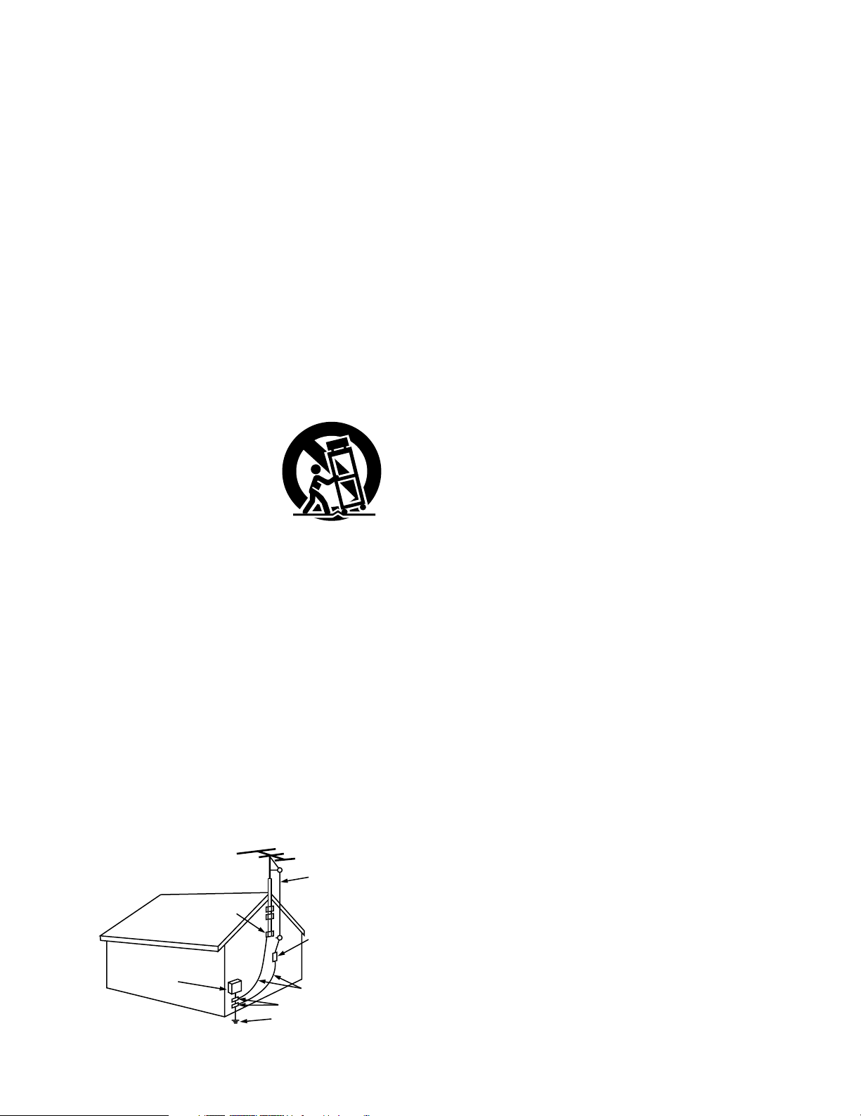
FIGURE A
EXAMPLE OF ANTENNA GROUNDING
AS PER NATIONAL
ELECTRICAL CODE
ANTENNA
LEAD IN
WIRE
GROUND
CLAMP
ELECTRIC
SERVICE
EQUIPMENT
ANTENNA
DISCHARGE UNIT
(NEC SECTION 810-20)
GROUNDING CONDUCTORS
(NEC SECTION 810-21)
GROUND CLAMPS
POWER SERVICE GROUNDING
ELECTRODE SYSTEM
(NEC ART 250, PART H)
NEC - NATIONAL ELECTRICAL CODE
Page 4

4
2 INTRODUCTION
Thank you for choosing the DENON AVR-5805 Digital Surround A / V receiver. This remarkable component has been engineered to provide superb
surround sound listening with home theater sources such as DVD, as well as providing outstanding high fidelity reproduction of your favorite music
sources.
As this product is provided with an immense array of features, we recommend that before you begin hookup and operation that you review the
contents of this manual before proceeding.
TABLE OF CONTENTS
z
Before Using...............................................................................6
x
Cautions on Installation............................................................6
c
Cautions on Handling................................................................7
v
Features..................................................................................7~9
b
Connections ...............................................................................9
Connecting Audio Components.................................................10
Connecting Video Components.................................................11
Connecting video components equipped with S-Video
jacks...........................................................................................12
Connecting video components equipped with Component
Video video jacks .......................................................................13
Video Conversion Function..................................................13, 14
Connecting equipment with HDMI terminals............................14
Connecting equipment with DVI terminals ...............................15
Connecting the antenna terminals.............................................16
Connecting the external input (EXT.IN) jacks ............................16
Connecting the ZONE2 jacks.....................................................17
Connecting a component with video and audio jacks to
the V.AUX input jacks ................................................................17
DENON LINK connections.........................................................18
Connecting IEEE1394 devices...................................................19
Speaker system connections ..............................................20, 21
n
Part Names and Functions
Front panel...........................................................................22, 23
Display .......................................................................................24
Remote control unit...................................................................25
m
System Setup...........................................................................26
System setup items and default values..............................26~28
Speaker system layout ..............................................................29
Before setting up the system....................................................30
Auto Setup / Room EQ..............................................................30
Measurement flow ...............................................................31
Before performing the Auto Setup procedure .....................32
(I) Connecting the microphone for Auto Setup ........................32
[1] Auto Setup / Room EQ......................................................33
1-1. Setting the Auto Setup.........................................................33
(II) Extra Setup ...........................................................................34
(
III
)Preliminary measurements...................................................35
(IV) Speaker System measurement......................................36, 37
(V) Check of the measurement result .................................38, 39
About the error message .....................................................39
1-2. Setting the Room EQ Setup...........................................40, 41
1-3. Setting the Direct Mode.......................................................41
1-4. Setting the MIC Input Select................................................42
Specifications and setup procedure
for Non-DENON microphone ...................................42, 43
1-5. Check the Parameter .....................................................43~46
[2] Speaker Setup ....................................................................46
2-1. Setting the type of speakers..........................................46, 47
2-2. Setting the low frequency distribution .................................48
2-3. Setting the Delay Time ...................................................49, 50
2-4. Setting the Channel Level..............................................51, 52
2-5. Setting the Crossover Frequency.........................................53
Setting the crossover frequency individually
for the different channels...............................................54
2-6. Selecting the Surround Speakers for the
different surround modes.....................................................55
2-7. Setting the THX Audio Setup
[1] Setting for using a THX Ultra2 compatible
subwoofer ......................................................................56
[2] Surround Back Speaker Position Settings......................57
[3] Audio Input Setup ..............................................................58
3-1. Setting the Digital In Assignment ..................................58, 59
3-2. Setting the EXT.IN Setup................................................60, 61
3-3. Setting the Input Function Level ..........................................62
3-4. Setting the Function Rename ........................................63, 64
3-5. Setting the IEEE1394 Assign ...............................................65
3-6. Selecting the IEEE1394 Auto Function ................................66
3-7. Tuner Presets
[1] Auto Preset Memory......................................................67
[2] Preset Skip .....................................................................68
[3] Preset Name ............................................................69, 70
[4] Video Setup ........................................................................71
4-1. Setting the Component In Assign..................................71, 72
4-2. Setting the Video Convert Mode....................................72, 73
4-3. Setting the Video Scaler.................................................73, 74
4-4. Setting the 3D Y/C Separation..............................................74
4-5. Setting the HDMI/DVI In Assign ....................................75, 76
4-6. Setting the Audio Delay..................................................76, 77
4-7. Setting the On Screen Display (OSD) ............................77, 78
[5] Advanced Playback ............................................................78
5-1. Setting the 2ch Direct/Stereo...............................................79
Setting the front B speakers when the surround
mode is set to the 2-channel Direct or Stereo...............79
5-2. Setting the Dolby Digital Setup ............................................80
5-3. Setting Auto Surround Mode ...............................................81
5-4. Setting the Manual EQ Setup ........................................82, 83
Procedure for copying the “Flat” correction curve........84
[6] Zone Setup (Zone2 = 5.1/7.1ch)........................................85
6-1. Setting the type of speakers for Zone2................................86
6-2. Setting the low frequency distribution for Zone2.................87
6-3. Setting the Delay Time for Zone2 ..................................88, 89
6-4. Setting the Channel Level for Zone2 ............................90, 91
6-5. Setting the Crossover Frequency for Zone2 ........................92
6-6. Setting the Video Setup for Zone2
[1] Video Convert Mode ................................................93, 94
[2] Audio Delay ....................................................................94
6-7. Zone3 and Zone4 tone control and channel level
setting.............................................................................95, 96
Zone Setup setting when Zone2 is set to STEREO or
MONO..........................................................................................96
[7] Option Setup.......................................................................97
7-1. Setting the Channel Setup ...................................................97
Channel setup flow ..................................................97, 98
The number of channels that can be selected ..............99
The subwoofer output composition...............................99
Connecting the preouts................................................100
7-2. Setting the Power Amplifier Assignment...........................101
Power amplifier assignment flow ........................101, 102
Amp Assign mode........................................................103
Bi-Amp connection.......................................................103
Table of power amplifier assignment modes ......103~105
Table of channels to which power amplifiers can
be assigned ..................................................................105
Page 5

5
7-3. Setting the Volume Control........................................106, 107
7-4. Setting the Trigger Out ...............................................107, 108
7-5. Setting the AC Outlet Assign.....................................109, 110
7-6. Protecting the setting and memory backup
[1] User Memory.......................................................110, 111
[2] Setup Lock ...........................................................111, 112
After Completing system setup.................................................112
,
Remote Control Unit
Inserting the Batteries .............................................................113
Using the Remote Control Unit ...............................................113
Operating DENON audio components ............................114, 115
Preset memory........................................................................116
Operating a component stored in the preset memory ...117, 118
Learning function.....................................................................119
System call ......................................................................120, 121
Punch Through ........................................................................121
Setting the back light’s lighting time.......................................122
Setting the brightness .............................................................122
Resetting .........................................................................123, 124
.
Operation
Operating the Remote control unit..........................................125
Before operating......................................................................125
Playing the input source..................................................126, 127
Playback using external input (EXT.IN) jacks ...........................128
Playing audio sources (CDs and DVDs)...................................129
After stating playback
[1] Setting the Room EQ...................................................130
[2] Listening over headphone............................................130
[3] Turning the sound off temporarily (MUTING)...............130
[4] Combining the currently playing sound with
the desired image (VIDEO SELECT) ............................130
[5] Checking the currently playing program source, etc. ..131
[6] Switching the surround speakers ................................131
[7] Switching between HDMI and DVI monitor output.....131
[8] Selection of resolution setting (SCALE).......................132
Multi-source recording/playback
[1] Playing one source while recording another
(REC OUT mode)..........................................................132
[2] Recording Dolby Digital and DTS multichannel
sources.........................................................................133
[3] Dolby Headphone recording.........................................133
⁄0
Surround
Adjustment steps that need to be performed prior to
surround sound playback
[1] Test Tone......................................................................134
[2] Channel Level.......................................................134, 135
Fader function..........................................................................135
Playing modes for different sources .......................................136
THX Surround EX / Home THX Cinema mode
[1] Playing sources recorded in Dolby Surround in the
Home THX Cinema surround mode.....................137, 138
[2] To play in the THX Surround EX/Home THX Cinema
Surround mode for sources recorded in Dolby Digital
or DTS ..........................................................................139
Dolby Digital mode and DTS Surround............................140, 141
Dolby Pro Logic IIx (Dolby Pro Logic II) mode................142, 143
DTS NEO:6 mode............................................................144, 145
The Dolby Headphone.....................................................145, 146
Memory and call-out functions (USER MODE function) .........146
⁄1
DENON Original Surround Modes
Surround modes and their features.........................................147
DSP surround simulation.................................................148, 149
Tone control setting
[1] Adjusting the tone using the Remote control
unit .......................................................................149, 150
[2] Adjusting the tone from the Main unit.........................150
⁄2
Multi Zone
Multi-zone playback with multi-source ....................................151
[1] ZONE2 playback ..................................................152~154
[2] ZONE3 playback...........................................................155
[3] ZONE4 playback...........................................................156
[4] Outputting a program source to amplifier, etc., in a
Zone2 room (ZONE2 SELECT mode)...........................157
[5] Outputting a program source to amplifier, etc., in a
Zone3 or Zone4 room
(ZONE3, ZONE4 SELECT mode)..................................157
Remote control unit operations during multi-source
playback ...................................................................................158
System Setup for multi-zone...................................................159
Adjustment steps that need to be performed prior to
surround sound playback in Zone2
[1] Test Tone......................................................................159
[2] Channel Level...............................................................160
Fader function..........................................................................161
Zone2 Surround .......................................................................162
Memory and call-out functions of Zone2
(USER MODE function) ...........................................................163
Zone2 tone control setting ..............................................164, 165
⁄3
Listening to the Radio
Auto tuning ..............................................................................165
Manual tuning..........................................................................166
Preset memory........................................................................167
Checking the preset stations...................................................168
Recalling preset stations .........................................................168
RDS (Radio Data System)........................................................169
RDS search..............................................................................170
PTY search...............................................................................171
TP search.................................................................................172
RT (Radio Text).........................................................................173
⁄4
Last Function Memory ..........................................................173
⁄5
Initialization of the Microprocessor.....................................173
⁄6
Troubleshooting.....................................................................174
⁄7
Additional Information
Optimum surround sound for different sources......................175
Surround back speakers ..........................................................176
Speaker setting examples
[1] For THX Surround EX systems
(using surround back speakers) ...........................177, 178
[2] When not using surround back speakers ....................178
Surround
[1] Dolby Surround ....................................................179, 180
[2] DTS Digital Surround............................................180, 181
[3] DTS-ES Extended Surround™......................................181
[4] DTS 96/24 ....................................................................182
[5] Home THX Cinema Surround...............................182, 183
[6] THX Surround EX .........................................................183
Audyssey MultEQ XT ..............................................................184
HDCD.......................................................................................184
DENON LINK ...........................................................................185
About IEEE1394 ......................................................................185
About HDMI.............................................................................185
Advanced AL24 Processing.....................................................185
Surround modes and parameters....................................186, 187
Relationship between the video input signal and
monitor output (MAIN ZONE)..................................................188
Relationship between the video input signal and
monitor output (ZONE2) ..........................................................189
⁄8
Specifications.................................................................190, 191
Page 6
6
1
BEFORE USING
2
CAUTIONS ON INSTALLATION
Pay attention to the following before using this unit:
• Moving the set
To prevent short circuits or damaged wires in the connection cords,
always unplug the power cord and disconnect the connection
cords between all other audio components when moving the set.
• Before turning the power switch on
Check once again that all connections are proper and that there are
not problems with the connection cords. Always set the power
switch to the standby position before connecting and disconnecting
connection cords.
• Store these instructions in a safe place.
After reading, store these instructions along with the warranty in a
safe place.
• Note that the illustrations in these instructions may differ
from the actual set for explanation purposes.
Noise or disturbance of the picture may be generated if this unit or
any other electronic equipment using microprocessors is used near a
tuner or TV.
If this happens, take the following steps:
• Install this unit as far as possible from the tuner or TV.
• Set the antenna wires from the tuner or TV away from this unit’s
power cord and input/output connection cords.
• Noise or disturbance tends to occur particularly when using indoor
antennas or 300 Ω/ohms feeder wires. We recommend using
outdoor antennas and 75 Ω/ohms coaxial cables.
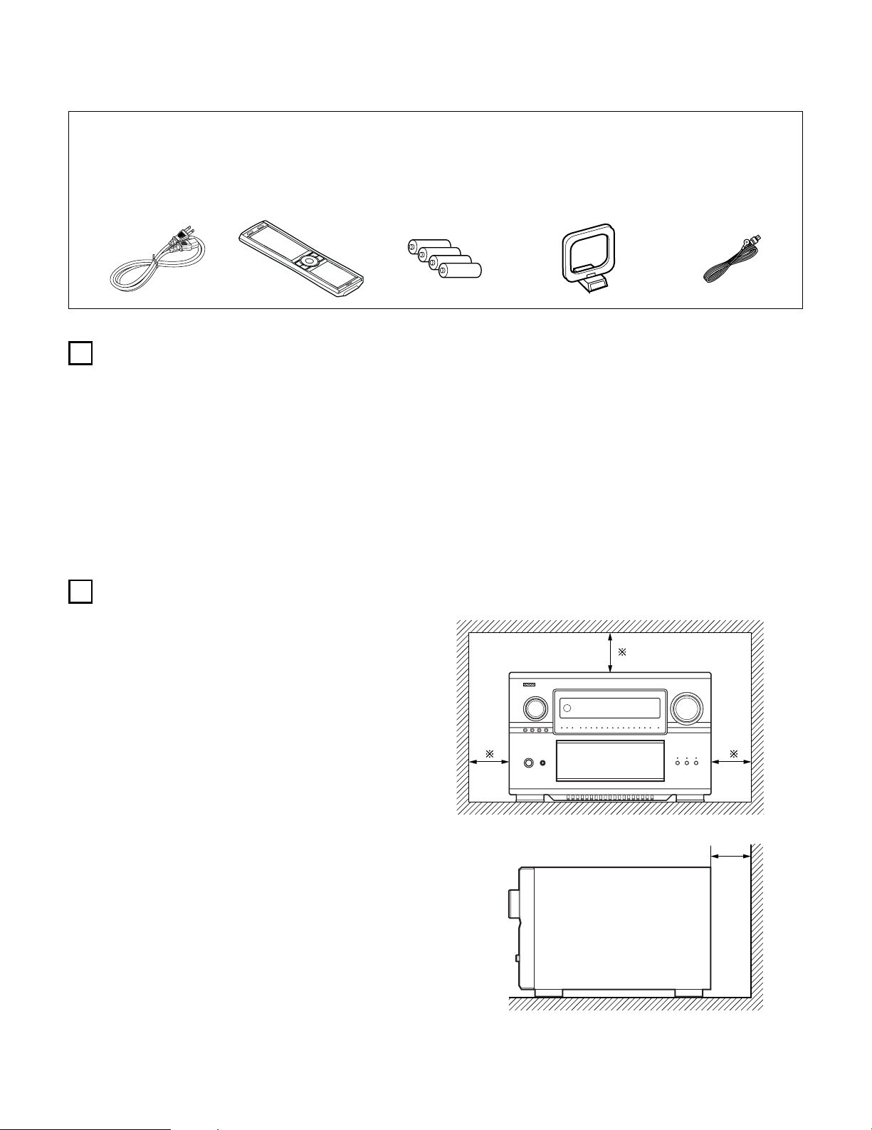
For heat dispersal, leave at least 10 cm of space between the top,
back and sides of this unit and the wall or other components.
4 inch/10 cm or more
Wall
4 inch/10 cm or more
2 ACCESSORIES
Check that the following parts are included in addition to the main unit:
q Operating instructions ............................................................................1
w Warranty (for North America model only)...............................................1
e Service station list...................................................................................1
r AC cord...................................................................................................1
t Remote control unit (RC-995).................................................................1
r
t
yui
y R03/AAA alkaline batteries .....................................................................4
u AM loop antenna ....................................................................................1
i FM indoor antenna..................................................................................1
o List of preset codes................................................................................1
Page 7

7
4
FEATURES
1. DENON Proprietary Digital Technology
1) NEW D.D.S.C.-Digital (Dynamic Discrete Surround Circuit)
Powered by four high performance, high speed 32 bit floating
point DSP processors, the AVR-5805 represents the pinnacle
of precision DSP processing technology. Unlike competitive
units, DENON’s discrete surround technology consists of
selected individual processors and ancillary elements, working
in harmony via proprietary DENON inter-IC digital communication
technology.
2) DENON Link
With select DENON DVD players that feature DENON Link
digital outputs, encrypted digital multi-channel audio transfers
to the AVR-5805 directly, eliminating unnecessary digital-toanalog and subsequent analog-to-digital conversions for the
highest possible signal transfer integrity. The DENON Link
function supports up to ultra high resolution 192 kHz DVD-A
digital datastreams, for maximum reproduced fidelity.
3) Latest AL24 DSP Processing
DENON’s acclaimed Advanced AL24 DSP processing improves
the fidelity of high resolution stereo PCM sources such as CD
and DVD (up to 192 kHz sampling frequencies), by
sophisticated DSP processing algorithms that improve low
level detail and enhance fidelity by upsampling and adaptive
filtering techniques. Advanced AL24 provides increased
dynamic range and spatial information; bring out all the
nuances with optimum clarity and natural fidelity.
4) AL24 DSP Processing For All Channels
For the AVR-5805, DENON’s AL24 processing supports multichannel DVD-Audio for all channels, including the Zone2 multichannel theater channels, for optimum fidelity and low level
detail reproduction in both the main zone as well as the second
multi-channel Zone2 system.
2. Latest Surround Decoding Technology
1) Dolby Digital
Using advanced digital audio compression and decoding
technologies, Dolby Digital provides up to 5.1 channels of wide
bandwidth, wide dynamic range multi-channel high fidelity
surround sound. Dolby Digital is the default digital multichannel audio delivery system for DVD and USA/Canada high
definition television systems.
2) Dolby Pro Logic IIx
Dolby Pro Logic
IIx adds the ability to provide up to 7.1 channel
reproduction from conventional stereo (2 channel) sources,
including surround back reproduction with a 6.1 or 7.1 surround
sound system. Pro Logic IIx has three modes: one for moviebased soundtracks; one for stereo music sources, and a game
mode for game consoles with stereo (2 channel) audio outputs.
3) Dolby Headphone
Developed jointly by Dolby Laboratories and Lake Technology
Ltd. of Australia, Dolby Headphone decoding provides thrilling
surround sound effects of your favorite movie and music
sources when using conventional stereo headphones.
4) DTS (Digital Theater Systems)
DTS provides up to 5.1 channels of wide-range, high fidelity
surround sound from sources such as DTS-encoded CDs,
DVDs with DTS soundtracks, and DVD-Audio discs that provide
DTS soundtracks.
5) DTS-ES Extended Surround and DTS Neo:6
The AVR-5805 also supports the DTS-ES 6.1 matrix and
discrete encoded surround formats, and also features DTS
Neo:6 stereo-to-surround decoding with both Music and Movie
modes for superb surround sound from conventional stereo
sources.
6) DTS 96/24 Decoding
Digital Theater Systems 96/24 provides ultra high resolution 24
bit, 96 kHz sampling for optimum wide bandwidth fidelity and
superb dynamic range. The AVR-5805 is equipped to faithfully
decode DTS 96/24 discs.
7) HDCD High Definition Compatible Digital
Using sophisticated encoding and decoding technologies, the
HDCD format provides improved fidelity and dynamic range
from encoded Compact Discs (which number in the thousands
of titles). The AVR-5805, via a standard digital audio connection
from a CD player or DVD player, internally recognizes and
decodes HDCD discs for optimum fidelity and widest dynamic
range.
8) Home THX Ultra2 Certified
Home THX is the unique collaboration between THX Ltd. and
audio/video equipment manufacturers. THX Ultra2 certification
is the highest performance level, and provides a rigorous set of
performance standards along with proprietary surround sound
post-processing technologies, all designed to maximize the
surround soundtrack playback experience in the home theater.
In addition, the AVR-5805 is fully compatible with THX
Surround EX, which provides extended surround sound via
additional surround back channel reproduction, first employed
on Lucasfilms’ Star Wars Episode 1 – The Phantom Menace,
and featured on many major motion pictures since. As well,
the AVR-5805’s power amplifier section fully complies with the
latest THX Ultra2 standards, and two new addition surround
modes are also provided – THX Ultra2 Cinema mode and THX
Music mode. In addition, the AVR-5805 also incorporates THX’s
new THX Games mode, for thrilling surround sound effects
from two channel game box audio sources.
3
CAUTIONS ON HANDLING
• Switching the input function when input jacks are not
connected
A clicking noise may be produced if the input function is switched
when nothing is connected to the input jacks. If this happens,
either turn down the MASTER VOLUME control or connect
components to the input jacks.
• Muting of PRE OUT jacks and SPEAKER terminals
The PRE OUT jacks and SPEAKER terminals include a muting
circuit. Because of this, the output signals are greatly reduced for
several seconds after the power switch is turned on or input
function, surround mode or any other-set-up is changed. If the
volume is turned up during this time, the output will be very high
after the muting circuit stops functioning. Always wait until the
muting circuit turns off before adjusting the volume.
• Whenever the power switch is in the STANDBY state, the
apparatus is still connected on AC line voltage.
Please be sure to turn off the power switch or unplug the cord
when you leave home for, say, a vacation.
Page 8

8
3. Movie & Music Surround For The Whole House
The AVR-5805’s versatile Multi Source functions let you select
different audio and video sources for each room in your home.
Different audio and video multi-channel sources can be enjoyed in
the home theater (Main room), as well as a multi-channel audio
and video source directed to a second room. Additional zones (3
and 4) can also receive video and stereo audio as well. The AVR5805 features Freely Assignable Ten Power Amp Channels, so
that you can decide which power amp channels can be dedicated
to the main zone, the secondary zone (Zone2) as well as to two
additional zones (Zone3 and Zone4), as well as providing line level
outputs to external power amplifiers.
1) Zone2 Theater Capability
With up to 9.1 system in the main home theater room, the
AVR-5805 provides for a second, fully 5.1 capable system in
Zone2, with component video and five amplifier channels as
well, with video up-conversion if desired.
2) Zone3 Independent Audio & Video
The AVR-5805 provides the ability for a third independent zone,
with selectable audio and video sources.
3) Zone4 Independent Audio
Zone4 is ideal for a room where you can enjoy a different
stereo source, for background music listening.
4. Ten High Power Assignable Power Amplifiers
1) Featuring high current, THX-certified high power amplifier
channels, the AVR-5805 is equipped to drive high performance
loudspeakers with unprecedented dynamic range and low
impedance drive capability, with each of the ten amplifier
channels rated at 170 W into 8 Ω/ohms. Each channel can be
freely assigned to the main home theater room, as well as
assigned to additional zones for multi-channel or stereo or even
monophonic distributed audio/video and audio-only functions.
For example, you might choose to have seven amplifier
channels dedicated to a full THX Surround EX & DTS Surround
EX 7.1 channel system in the main room, while still allowing a
powered stereo function in the second zone, and a third
monophonic background music function in another room. Or,
you could have a principal 5.1 channel setup in the main home
theater room, while having a secondary powered 5.1 system in
the second zone. You could even have (with compatible biamplified-capable speakers) a true 5.1 bi-amped system in the
main room, along with additional line-level-powered systems in
up to three additional rooms.
5. Audiophile Audio Quality Throughout
1) Separated Pure Audio & Video Chassis Construction
For optimum audio and video quality, the AVR-5805 features
dedicated and physically separated low and high level audio
and video circuits to prevent degrading mutual interference.
2) Optimum Chassis Stability
As the AVR-5805 is equipped with a massive toroidal main
power supply and additional secondary power supplies,
centrally located within the chassis, a fifth chassis foot helps
reduce the physical vibration that can cause mechanicallyinduced vibration-related distortions.
3) Multiple Separate Power Supply Topologies
No less than six individual power transformers (one very large
toroidal unit, and five additional lower voltage power
transformer units) are provided, ensuring that each critical subsection draws power from its own dedicated supply,
eliminating minute fluctuations that occur with single
transformer-equipped competitive units.
4) Multiple Toroidal Sub-Windings
The massive main toroidal power transformer (which powers
the ten amplifier channels block) features dedicated subwindings and high current, ultra stable DC rectifiers and high
rated smoothing/storage capacitors, with a tremendous
132,000 µF total storage capacity.
5) Pure Direct Mode
According to the selected input source, the Pure Direct Mode
provides the optimum decoding by switching off any and all
unnecessary processing (video disable, tone bybass, and other
unnecessary circuits).
6) Dual Surround Speaker Mode
DENON was the first to introduce Dual Surround Mode
Speaker Switching, where two different types (and positions)
of surround speakers could be chosen according to the source
material – diffuse surround speakers located at the sides of the
listening position for movie surround sound, and directional
surround speakers located at the room’s rear corners for music
surround sound. The AVR-5805 also adds the ability to have
both powered (AVR-5805 amplified) music and surround sound
speaker systems, according to each individual home theater’s
setup circumstances.
7) Highest Quality Input & Output Terminals
The AVR-5805 audio and video input terminals are gold-plated,
as are the ten speaker terminal pairs, which accept bare wire
as well as banana plugs.
6. High Resolution Video Section
1) Component Video Switching
In addition to composite and S-video switching, the AVR-5805
provides no less than five sets of component video inputs via
RCA-type coaxial connectors, as well as an additional sixth set
of component video inputs via BNC connectors, as well as two
sets of component video outputs (one for RCA-type coaxial,
one for BNC connectors), with additional capability for
component video output to Zone2. These component video
circuits are fully HD-compatible, with a flat response to 100
MHz, far above the 38 MHz requirement for true HD
reproduction, ensuring crisp and clear HDTV picture quality.
2) Video Up And Down Conversion Function
To eliminate video signal incompatibility, the AVR-5805 is
equipped with video up-conversion and down-conversion.
Composite and S-video signals are internally up-converted to
component video for the main zone, and down-converted for
480i component video signals. Zone2 features downconversion from S-video to composite video.
3) Progressive Scanning & Scaling Function
Via high quality Faroudja DCDi™ (*1) processing, the AVR-5805
converts standard definition interlaced video to higher
resolution progressive scanning format – 480i interlace to 480p
progressive. For non-copy-protected video signals, further upconversion to HD 1080i video is also provided, for highest
visual quality with compatible HD video displays.
4) High Resolution 12 bit/216 MHz Video D/A Conversion
Featuring Analog Devices ADV-7310 Noise Shaped Video (*2)
digital-to-analog converters, the AVR-5805 provides superior
high resolution video output free from video noise and
conversion artifacts.
5) Superior S-video Processing
A 3-dimensional Y-C separation circuit provides artifact-free
composite video to S-video up-conversion, and Time Base
Correction for optimum color sharpness with composite video
inputs (main zone).
7. Latest Digital A/V Input/Output Capability With Future Upgrade
Ability
1) HDMI/DVI Switching
High Definition Multi-media Interface provides digital audio and
video signal transfer between source components, the AVR5805, and compatible video displays with HDMI digital
interface. Digital Visual Interface provides similar digital
input/output capability for digital video signals. The AVR-5805 is
equipped with three HDMI inputs and one DVI input, and one
each HDMI and DVI outputs to compatible video displays. Each
HDMI/DVI input feeds both HDMI and DVI outputs, for
optimum compatibility with today’s HDMI- and DVI-equipped
video displays.
Page 9

9
5
CONNECTIONS
• Do not plug in the AC cord until all connections have been
completed.
• Be sure to connect the left and right channels properly (left with
left, right with right).
• Insert the plugs securely. Incomplete connections will result in
the generation of noise.
• Use the AC OUTLETS for audio equipment only. Do not use
them for hair driers, etc.
• Note that binding pin plug cords together with AC cords or
placing them near a power transformer will result in generating
hum or other noise.
• Noise or humming may be generated if a connected audio
equipment is used independently without turning the power of
this unit on. If this happens, turn on the power of the this unit
.
2) IEEE 1394 Compatability
Two IEEE 1394 digital interface inputs are provided, allowing
SACD DSD and DVD-Audio digital audio signal input capability
with select DENON DVD players that feature IEEE 1394 digital
output function, and feature DENON’s D.A.S.S. (DENON Audio
Synchronized System) function, which reduces data jitter for
superior high resolution DSD and PCM reproduction.
3) Ethernet Function
For full compatibility with external control systems, such as
AMX and Crestron, the AVR-5805 features Ethernet
connectivity.
4) RS-232C Serial Input/Output Function
For full compatibility with external control systems, such as
AMX and Crestron, the AVR-5805 features a RS-232C serial I/O
port. A second RS-232C serial I/O port is provided on the front
panel, for future software and system upgrade capability.
5) Future Surround Format Inputs & Outputs
For possible future surround sound formats, the AVR-5805
features up to ten channel audio inputs (nine main channels
plus an additional low frequency effects channel), with high
resolution A/D conversion on each input. A second set of 5.1
analog inputs is also provided, for connection to surround
sources such as SACD and/or DVD-Audio players.
8. Easy-To-Use Functions
1) Automatic Setup With Room Equalization
Featuring the newest Audyssey MultEQ XT technology, the
AVR-5805 provides automatic room equalization with multiple
measurement points for optimum response throughout the
listening room.
2) Three User-Definable Easy Modes
Three User Modes are provided, allowing you to store and
recall your favorite surround modes with individual level
memories at the touch of a button.
3) Digital Audio Delay Function
For optimum picture and sound synchronization, the AVR-5805
features an adjustable digital audio delay function, variable
from 0 ~ 200 milli-seconds.
4) Adjustable Crossover Frequencies
For the widest compatibility with various main speaker and
subwoofer combinations, the AVR-5805 is equipped with a
choice of ten different crossover frequencies (40, 60, 80, 90,
100, 110, 120, 150, 200 and 250 Hz crossover points),
individually adjustable for each of the main speaker systems.
5) The AVR-5805 provides dual subwoofer outputs, along with an
additional subwoofer output dedicated for the Low Frequency
Effects channel (main zone).
6) Auto Surround Mode
For each input source, a separate memory stores your
preferred surround sound mode and other settings, eliminating
the need to re-configure the surround mode parameters
whenever you switch between input sources.
7) Assignable High Current Trigger Outputs
Four different 12 Volt trigger outputs allow the automatic
activation of externally controlled devices, such as motorized
drop-down screens, motorized drapery, motorized screen
masking systems and other trigger-activated systems. Each
port supports 12V/250mA trigger-activated functions,
assignable by zone (Main Zone, Zone2, Zone3, or Zone4).
8) Assignable AC Outlets
Three assignable AC convenience outlets are provided, and
each can be activated by choice of input source or surround
sound mode by each zone, to activate specific external
components as necessary.
9) Front Panel Convenience Inputs
A set of front panel A/V inputs allows quick connection of A/V
sources, such as a video camcorder or a game console.
10) Electro-Luminescent Membrane Touch-Panel Remote Control
Featuring back-lit EL technology, the AVR-5805 remote control
displays a specific function key set for each selected
component, and is pre-programmed with hundreds of remote
control code sets and features learning capability as well.
11) Large Fluorescent Display
For easy setup and system monitoring, the AVR-5805 features
a clearly readable FL display that provides extensive system
status and setup monitoring.
12) Preset Memory Tuning
Up to 56 AM and FM stations can be stored in the tuner
memory, in any combination and in any order of AM and FM
stations.
13) AC Input
Detachable AC Cord.
14) Other Useful Functions
Digital Audio Input to Analog Recording Output conversion
Input Source Re-naming Function
Audio Level Memories for each input
Personal Memory Plus function stores surround mode, level
memories, analog or digital input selection for each input
Volume Level Limiter provides a user-definable pre-set volume
level for multi-zone audio operation
Power On Volume Level Memory provides a user-definable
volume level that is activated every time the AVR-5805 is
powered up
Setup Lock Function prevents mis-operation at start-up
Personal Default Memory function
RDS tuner capability
*1: “DCDi™” is trademark of Faroodja, a division of Genesis
Microchip Inc.
*2: “NSV” is a trademark of Analog Devices, Inc.
Page 10
10
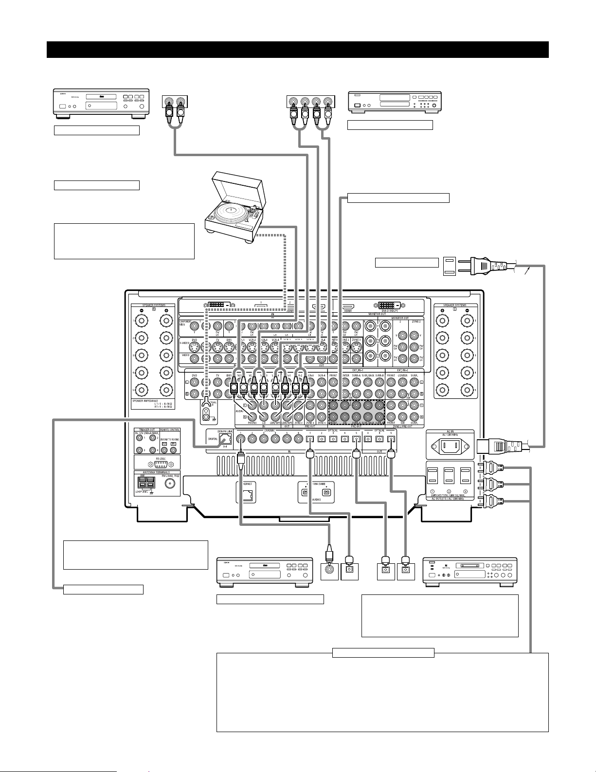
Connecting Audio Components
• When making connections, also refer to the operating instructions of the other components.
OUTPUT INPUT
OPTICAL
RLRL
OUTPUT INPUT
R
OUTPUT
L
OPTICALCOAXIAL
OUTPUT
RLR
L
R L R L
R
L
R
L
R
L
B
DIGITAL AUDIO
B
DIGITAL AUDIO
CD player
Connecting a CD player
Connect the CD player’s analog output
jacks (ANALOG OUTPUT) to this unit’s CD
jacks using pin plug cords.
Connecting a turntable
Connect the turntable’s output cord to the AVR-5805’s
PHONO jacks, the L (left) plug to the L jack, the R
(right) plug to the right jack.
NOTE:
This unit cannot be used with MC cartridges
directly. Use a separate head amplifier or step-up
transformer.
If humming or other noise is generated when the ground wire is connected,
disconnect the ground wire.
Turntable
(MM cartridge)
Ground wire
AC cord
(Supplied)
Connecting the pre-out jacks
Use these jacks if you wish to connect external power amplifier(s) to increase
the power of the front, center, surround and surround back sound channels,
or for connection to powered loudspeakers.
When using only one surround back speaker, connect it to left channel.
Connecting the AC OUTLETS
AC OUTLETS
• SWITCHED (total capacity – 120 W (1 A.))
The power to these outlets is turned on and off in conjunction with the POWER switch on the main unit, and when the
power is switched between on and standby from the remote control unit.
No power is supplied from these outlets when this unit’s power is at standby. Never connect equipment whose total
capacity is above 120 W (1 A.)
NOTES:
• Only use the AC OUTLETS for audio equipment. Never use them for hair driers, TVs or other electrical appliances.
• The AC outlets can be set to turn on and off for the different functions.
For details, see “Setting the AC Outlet Assign”. (See pages 109, 110)
AC outlets (wall)
AC 120V, 60Hz
MD recorder, CD recorder or other
component equipped with digital
input/output jacks
CD player or other component
equipped with digital output jacks
Connecting the DIGITAL jacks
Use these for connections to audio equipment with
digital output. Only one type of connector needs to
be used, you can decide which based on availability
of coaxial and optical inputs. Refer to pages 58, 59
for instructions on setting this terminal.
NOTES:
• Use 75 Ω/ohms cable pin cords for coaxial connections.
• Use optical cables for optical connections, removing the
cap before connecting.
Connecting a tape deck
Connections for recording:
Connect the tape deck’s recording input jacks (LINE IN or REC) to this unit’s
tape recording (OUT) jacks using pin plug cords.
Connections for playback:
Connect the tape deck’s playback output jacks (LINE OUT or PB) to this unit’s
tape playback (IN) jacks using pin plug cords.
CD recorder or Tape deck
DENON Link terminal
Use this terminal to connect a DENON DVD player for
high quality digital multichannel sound.
(See page 18)
Route the connection cords, etc., in such a way that
they do not obstruct the ventilation holes.
Page 11
11
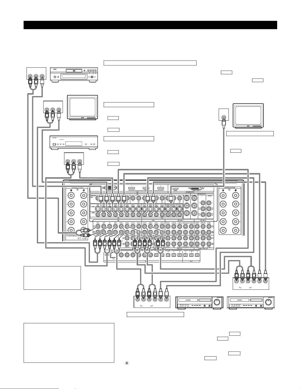
Connecting Video Components
•To connect the video signal, connect using a 75 Ω/ohms video signal cable cord. Using an improper cable can result in a drop in picture quality.
• When making connections, also refer to the operating instructions of the other components.
• The AVR-5805 is equipped with a function for up and down converting video signals. (See page 13)
The signal connected to the video signal terminal is output to the S-Video and component video monitor out terminals.
But the REC OUT terminals have no conversion function, so when recording connect the appropriate video terminals.
R OUT
VIDEO
OUT
L
AUDIO
R OUT
VIDEO
OUT
L
AUDIO
R OUT IN
AUDIO
VIDEO
OUT IN
LRL
R OUT IN
AUDIO
VIDEO
OUT IN
LRL
R OUT
VIDEO
OUT
L
AUDIO
IN
VIDEO
R
L
R
L
RLR
L
R
L
R
L
R
L
R
L
R
L
R
L
R
L
R
L
R
L
R
L
B
TV
DVD player or video disc player (VDP), etc.
Monitor TV
Connecting a TV tuner
TV
• Connect the TV’s tuner’s video output jack (VIDEO OUTPUT) to the
(yellow) TV IN jack using a 75 Ω/ohms video coaxial pin plug
cord.
• Connect the TV’s tuner’s audio output jacks (AUDIO OUTPUT) to the
TV IN jacks using pin plug cords.
AUDIO
VIDEO
C
onnecting a DVD player or a video disc player (VDP)
DVD
• Connect the video disc player’s video output jack (VIDEO OUTPUT) to the (yellow) DVD IN jack using a
75 Ω/ohms video coaxial pin plug cord.
• Connect the video disc player’s analog audio output jacks (ANALOG AUDIO OUTPUT) to the DVD IN
jacks using pin plug cords.
• VDP can be connected to the VDP jacks in the same way.
AUDIO
VIDEO
MONITOR OUT
• Connect the TV’s video input
jack (VIDEO INPUT) to the
MONITOR OUT jack
using a 75 Ω/ohms video
coaxial pin plug cord.
VIDEO
Note on connecting the digital
input jacks
• Only audio signals are input to
the digital input jacks. For details,
see page 10.
Video deck 2Video deck 1
• There are four sets of video deck (VCR) jacks, so four video decks can be connected for
simultaneous recording or video copying.
Video input/output connections:
• Connect the video deck’s video output jack (VIDEO OUT) to the (yellow) VCR-1 IN jack,
and the video deck’s video input jack (VIDEO IN) to the (yellow) VCR-1 OUT jack using
75 Ω/ohms video coaxial pin plug cords.
Connecting the audio output jacks
• Connect the video deck’s audio output jacks (AUDIO OUT) to the VCR-1 IN jacks, and the
video deck’s audio input jacks (AUDIO IN) to the VCR-1 OUT jacks using pin plug cords.
Connect other video decks to the VCR-2, VCR-3 or VCR-4 jacks in the same way.
AUDIO
AUDIO
VIDEO
VIDEO
Connecting the video recorders
Connecting a monitor TV
Connecting a DBS tuner
DBS
• Connect the DBS tuner’s video output jack (VIDEO OUTPUT) to the
(yellow) DBS IN jack using a 75 Ω/ohms video coaxial pin
plug cord.
• Connect the DBS tuner’s audio output jacks (AUDIO OUTPUT) to the
DBS IN jacks using pin plug cords.
AUDIO
VIDEO
NOTE:
• Connecting a LD (laser disc) player with a Dolby
Digital RF Output.
The AVR-5805 does not have a DD RF demodulator
function. Therefore, you need to use a commercially
available outboard DD RF demodulator and connect its
digital output to one of the AVR-5805 available digital
inputs. Refer to the demodulator’s owner’s manual for
further information.
DBS tuner
Page 12
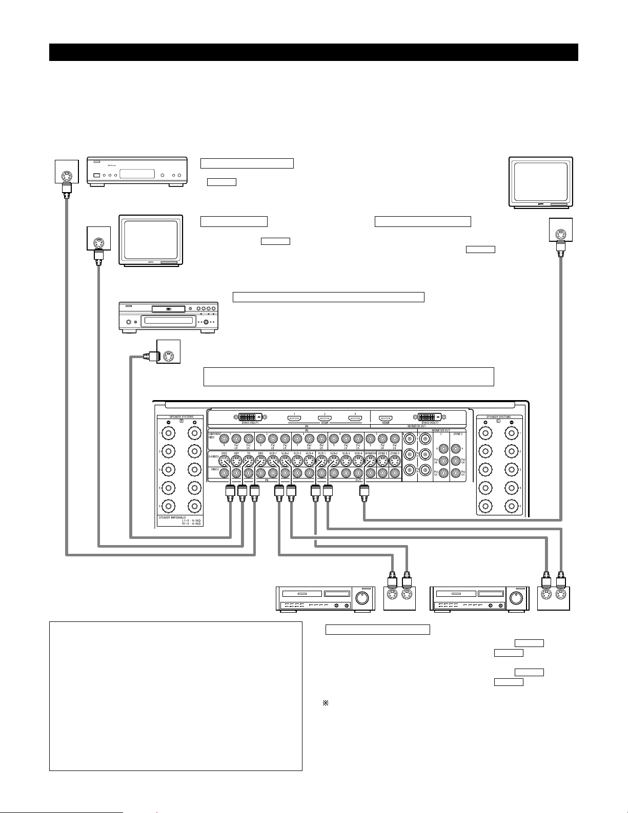
12
Connecting video components equipped with S-Video jacks
• When making connections, also refer to the operating instructions of the other components.
• A note on the S-Video input jacks
The input selectors for the S-Video inputs and Video inputs work in conjunction with each other.
• The AVR-5805 is equipped with a function for converting video signals. (See page 13)
The signal connected to the S-Video signal terminal is output to the composite video and component video monitor out terminals.
But the REC OUT terminals have no conversion function, so when recording connect the S-Video terminals.
OUT
S-VIDEO
OUT
S-VIDEO
OUT
S-VIDEO
IN
S-VIDEO
OUT IN
S-VIDEO
OUT IN
S-VIDEO
B
Monitor TV
Video deck 2Video deck 1
TV
Connecting a monitor TV
Connecting the video decks
Connecting a TV
MONITOR OUT
• Connect the TV’s or DBS tuner’s S video input
(S-VIDEO INPUT) to the MONITOR
OUT jack using a S jack connection cord.
S-VIDEO
• Connect the TV’s S video output jack (S-VIDEO
OUTPUT) to the TV IN jack using an S
jack connection cord.
S-VIDEO
• Connect the video deck’s S output jack (S-OUT) to the VCR-1 IN
jack and the video deck’s S input jack (S-IN) to the VCR-1 OUT jack
using S jack connection cords.
• Connect the video deck’s S output jack (S-OUT) to the VCR-2 IN
jack and the video deck’s S input jack (S-IN) to the VCR-2 OUT jack
using S jack connection cords.
Connect the third and fourth video deck to the VCR-3 and VCR-4 jacks in the
same way.
S-VIDEO
S-VIDEO
S-VIDEO
S-VIDEO
Connect the components’ audio inputs and outputs as described on page 10.
NOTES:
• The video signal ZONE2 MONITOR OUT (yellow), S-Video
signal ZONE2 MONITOR OUT jack or component signal ZONE2
MONITOR OUT output switches together with the input
function selected with the ZONE2 SELECT (See page 157). To
use as the monitor output, set “SOURCE” as the ZONE2 input
function. The on-screen display signals are output from the
ZONE2 MONITOR OUT (See pages 152~154).
• The video signal ZONE3 MONITOR OUT (yellow) or S-Video
signal ZONE3 MONITOR OUT output switches together with
the input function selected with the ZONE3/REC SELECT (See
page 157). To use as the monitor output, set “SOURCE” as the
ZONE3/REC SELECT input function. At this time, the on-screen
display signals are not output from the ZONE3 MONITOR OUT
(See page 155).
DVD player or video disc player (VDP)
Connecting a DVD player or a video disc player (VDP)
DVD
• Connect the DVD player’s S-Video output jack to the S-VIDEO DVD IN jack using a S-Video
connection cord.
• VDP can be connected to the VDP jacks in the same way.
• It is also possible to connect a video disc player, DVD player, video camcorder, game machine,
etc., to the V.AUX jacks.
Connecting a DBS tuner
• Connect the DBS tuner’s S video output jack (S-VIDEO OUTPUT) to the
DBS IN jack using an S-Video connection cord.
S-VIDEO
DBS tuner
Page 13
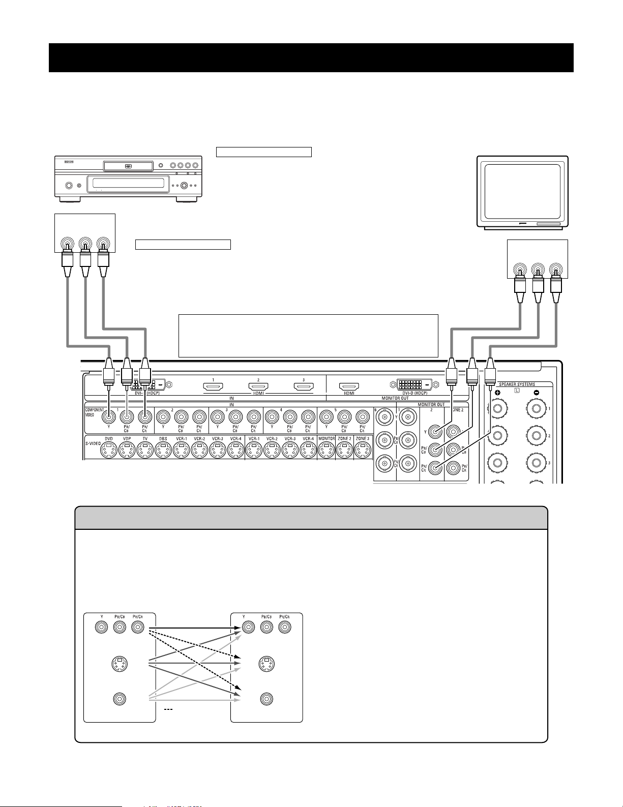
13
Connecting video components equipped with Component Video (color difference) video jacks
(Component - Y, Pb, Pr ; Y, Cb, Cr)
• When making connections, also refer to the operating instructions of the other components.
• The signals input to the component (color difference) video jacks are not output from the VIDEO output jack (yellow) or the S-Video output jack.
• Some video sources with component video outputs are labeled Y, P
B, PR, or Y, CB, CR, or Y, B-Y, R-Y. These terms all refer to component video
color difference output.
• The function assigned to the component video input can be changed at the system setup. For details, see “Setting the Component In Assign”.
(See pages 71, 72)
YPB PR
VIDEO IN
COMPONENT
YPB PR
VIDEO OUT
COMPONENT
DVD player Monitor TV
Connecting a DVD player
Connecting a monitor TV
DVD IN jacks
• Connect the DVD player’s component (color difference) video output jacks
(COMPONENT VIDEO OUTPUT) to the COMPONENT DVD IN jack using 75
Ω/ ohms coaxial video pin-plug cords.
• In the same way, another video source with component video outputs such
as a DTV/DBS tuner, etc., can be connected to the TV/DBS component
(color difference) video jacks.
MONITOR OUT jack
• Connect the TV’s component (color difference) video input jacks (COMPONENT VIDEO INPUT) to the
COMPONENT MONITOR OUT-2 jack using 75 Ω/ohms coaxial video pin-plug cords.
• Connect the TV’s component (color difference) video input jacks (COMPONENT VIDEO INPUT) to the
COMPONENT MONITOR OUT-1 jack using BNC connectors.
• The COMPONENT MONITOR OUT-1 and the COMPONENT MONITOR OUT-2 can be used simultaneously.
• The component video input and/or output jacks may be labeled differently
on some TVs, monitors or video components (Y, Pb, Pr; Y, Cb, Cr; Y, B-Y, RY). Check the owner’s manuals for other components for further
information.
(MONITOR OUT / ZONE2)
(MONITOR OUT / ZONE2)
(MONITOR OUT / ZONE2)
The Video Conversion Function
The AVR-5805 is equipped with a function for up and down converting video signals.
Because of this, the AVR-5805’s MONITOR OUT jack can be connected to the monitor (TV) with a set of cables offering a higher
quality connection, regardless of how the player and the AVR-5805’s video input jacks are connected.
Generally speaking, connections using the component video jacks offer the highest quality playback, followed by connections
using the S-Video jacks, then connections using the regular video jacks (yellow).
This unit’s input jacks This unit’s output jacks
The flow of the video signals.
(Component Video Jacks)
(S-Video jack)
(Video jack)
(Component Video Jacks)
(S-Video jack)
(Video jack)
Cautions on the Zone2 video conversion function:
There is no TBC (Time Base Collector) for Zone2.
When the component video terminals are used to connect
the AVR-5805 with a TV (or monitor, projector, etc.) and the
video (yellow) or S video terminals are used to connect the
AVR-5805 with a VCR, depending on the combination of the
TV and VCR the picture may flicker in the horizontal
direction, be distorted, be out of sync or not display at all
when playing video tapes.
If this happens, connect a commercially available video
stabilizer, etc., with a TBC (time base corrector) function
between the AVR-5805 and the VCR, or if your VCR has a
TBC function, turn it on.
( : only 480i/580i )
Page 14
14
NOTES:
•Video down conversion to the Main Zone’s monitor output is only possible when the component video input resolution is 480i (interlaced
standard definition video – NTSC format, for North America) or 576i (interlaced standard definition video – PAL format, for Europe and
other countries).
• This video conversion function cannot be used with HDMI or DVI video signals.
• When not using the S-Video monitor output connector for the Main zone or Zone2, the composite video input signal is given priority and
up-converted to a component video signal. To convert with priority to the S-Video input signal, set the video convert mode to “S-Video”.
To change the setting of the video conversion mode for the Main zone, see pages 72, 73.
To change the setting of the video conversion mode for the Zone2, see pages 93, 94.
• It is not possible to down-convert from the Zone2’s component video signal to a S-Video or composite signal, so when not using the
Zone2’s component monitor output connector, use an S-Video connection cord or composite connection cord to connect the AVR-5805
with the player.
OUT
HDMI
(HDCP)
HDMI IN
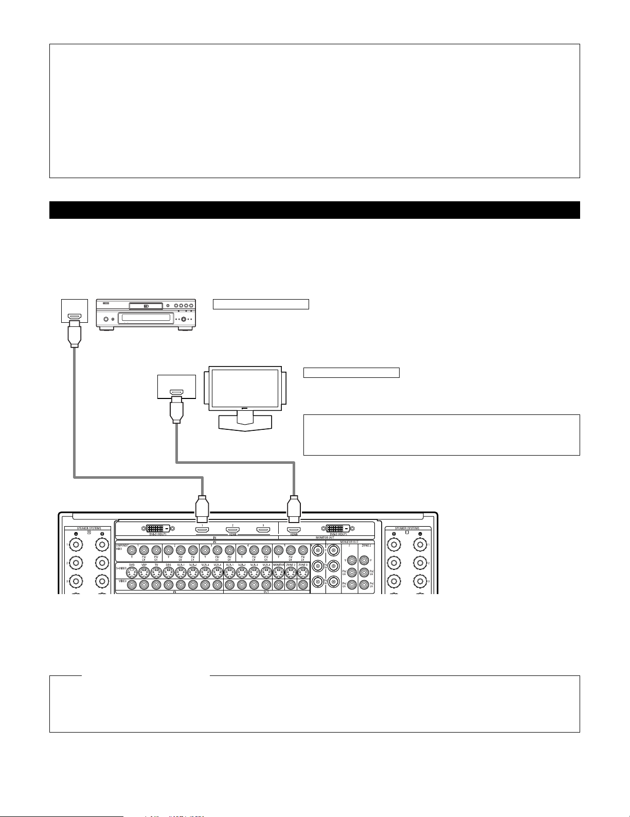
Connecting equipment with HDMI (High-Definition Multimedia Interface) terminals
•A simple 1-cable connection (using a commercially available cable) with a device having an HDMI (High-Definition Multimedia Interface) connector
allows digital transfer of the digital images of DVD video and other sources, and the multi-channel sound of DVD audio and DVD video.
• The HDMI and DVI-D monitor output connectors on the AVR-5805 can only be used one at a time, not simultaneously.
•To provide audio output from AVR-5805’s audio output connector, select “Amp” at the System Setup.
•To provide audio output from the TV, select “TV” at the System Setup. For details, see “Setting the HDMI/DVI In Assign”. (See pages 75, 76)
Connecting a monitor TV
HDMI MONITOR OUT terminal
• Connect the TV’s HDMI input terminals to the HDMI OUT terminal using HDMI
cable.
Connecting a DVD player
HDMI IN terminals
• Connect the DVD player’s HDMI output terminals to the HDMI IN terminal using HDMI cable.
•
Among the devices that support HDMI, some devices can control other devices via the HDMI connector; however, the
AVR-5805
cannot be controlled by another device via the HDMI connector.
•
The audio signals from the HDMI connector (including the sampling frequency and bit length) may be limited by the equipment that is
connected.
•
The on-screen display signals are not outputted from the HDMI MONITOR OUT.
HDMI cable
(commercially available)
To play back the digital video and audio of DVD video and DVD audio through an HDMI/DVI-D connection, both the connected player
and monitor are required to support a copyright protection system called HDCP (High-bandwidth Digital Content Protection System).
HDCP is copy protection technology that comprises data encryption and authentication of the partner equipment. The AVR-5805 supports
HDCP. Please see the user’s manual of your video display for more information about this.
Copyright Protection System
DVD player
Monitor equipped with
HDMI input connectors
HDMI cable
(commercially available)
NOTE:
• The audio signals on the multi/stereo area of super audio CDs are not output.
For DVD Audio discs that are copyright-protected by CPPM, neither the video nor
audio signals are output.
Page 15
15
OUT
DVI-D
(HDCP)
DVI-D IN
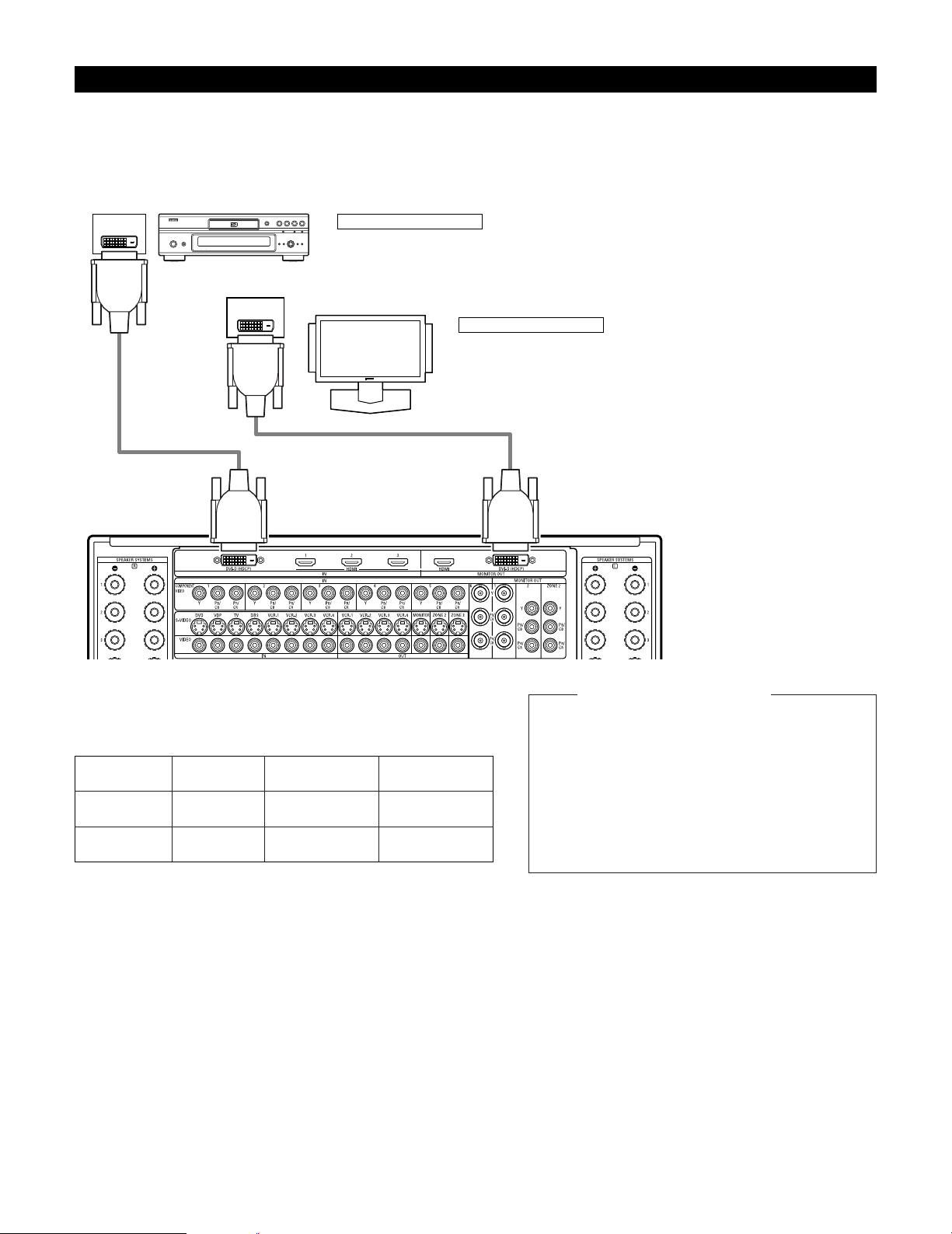
Connecting equipment with DVI (Digital Visual Interface) terminals
• Connection with equipment that has a DVI (Digital Visual Interface)-D connector permits the transfer of digital images. Make an audio
connection also.
• Commercially-available DVI cables are available in 24-pin and 29-pin types. The AVR-5805 supports the 24-pin DVI-D cable.
• The HDMI and DVI-D monitor output connectors on the AVR-5805 can only be used one at a time, not simultaneously.
• The on-screen display signals are not outputted from the DVI-D MONITOR OUT.
Connecting a monitor TV
DVI-D MONITOR OUT terminal
• Connect the TV’s DVI-D input terminal to the DVI-D MONITOR OUT terminal using
DVI-D cable.
Connecting a DVD player
DVI-D IN terminal
• Connect the DVD player’s DVI-D output terminals to the DVI-D IN terminal using DVI-D cable.
Note on connecting a HDMI/DVI
•
The table below indicates the compatibility of connections between
the HDMI/DVI-D output connector of the
AVR-5805 and monitors that
support HDMI/DVI-D.
24P DVI-D cable
(commercially available)
E
E
HDMI output
terminal
Monitor with
HDMI
C
(Video / Audio)
C
(Only Video)
DVI-D output
terminal
Monitor with DVI-D
(HDCP compatible)
C
(Only Video)
C
(Only Video)
Monitor with DVI-D
(HDCP incompatible)
24P DVI-D cable
(commercially available)
DVD player
Monitor equipped with
DVI-D input connectors
To play back the digital video and audio of DVD video
and DVD audio through an HDMI/DVI-D connection,
both the connected player and monitor are required to
support a copyright protection system called HDCP
(High-bandwidth Digital Content Protection System).
HDCP is copy protection technology that comprises data
encryption and authentication of the partner equipment.
The AVR-5805 supports HDCP. Please see the user’s
manual of your video display for more information about
this.
Copyright Protection System
Page 16
16
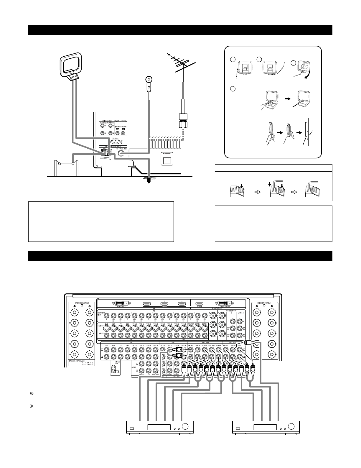
Connecting the antenna terminals
1
4
2
3
DIRECTION OF
BROADCASTING
STATION
75 Ω/ohms
COAXIAL
CABLE
FM ANTENNA
FM INDOOR
ANTENNA
(Supplied)
AM LOOP
ANTENNA
(Supplied)
AM OUTDOOR
ANTENNA
GROUND
AM loop antenna assembly
Connect to the AM
antenna terminals.
Remove the vinyl tie
and take out the
connection line.
Bend in the reverse
direction.
a. With the antenna
on top any stable
surface.
b. With the antenna
attached to a wall.
Mount
Installation hole
Mount on wall, etc.
• An F-type FM antenna cable plug can be connected directly.
Connection of AM antennas
1. Push the lever. 2. Insert the conductor. 3. Return the lever.
Note to CATV system installer:
This reminder is provided to call the CATV system installer’s attention to
Article 820-40 of the NEC which provides guidelines for proper grounding
and, in particular, specifies that the cable ground shall be connected to the
grounding system of the building, as close to the point of cable entry as
practical.
Notes:
• Do not connect two FM antennas simultaneously.
• Even if an external AM antenna is used, do not disconnect
the AM loop antenna.
• Make sure AM loop antenna lead terminals do not touch
metal parts of the panel.
Connecting the external input (EXT. IN) jacks
•AVR-5805 is equipped with two analog external input terminals for 9.1 channels and 5.1 channels.
• These jacks are for inputting multi-channel audio signals from an outboard decoder, or a component with a different type of multi-channel
decoder, such as a DVD Audio player, or a multi-channel SACD player, or other future multi-channel sound format decoder.
• When making connections, also refer to the operating instructions of the other components.
LRL
R
L
R
LRL
R
L
R
Decoder with 10-, 8- or 6-channel analog output
Front
Surround back
Surround A
Subwoofer
Center
For instructions on playback using the
external input (EXT. IN) jacks, see page 128.
See pages 60, 61 for “Setting the EXT.IN
Setup”.
Surround B
Surround
Subwoofer
Front
Center
Decoder with 6-channel analog output
Page 17
17
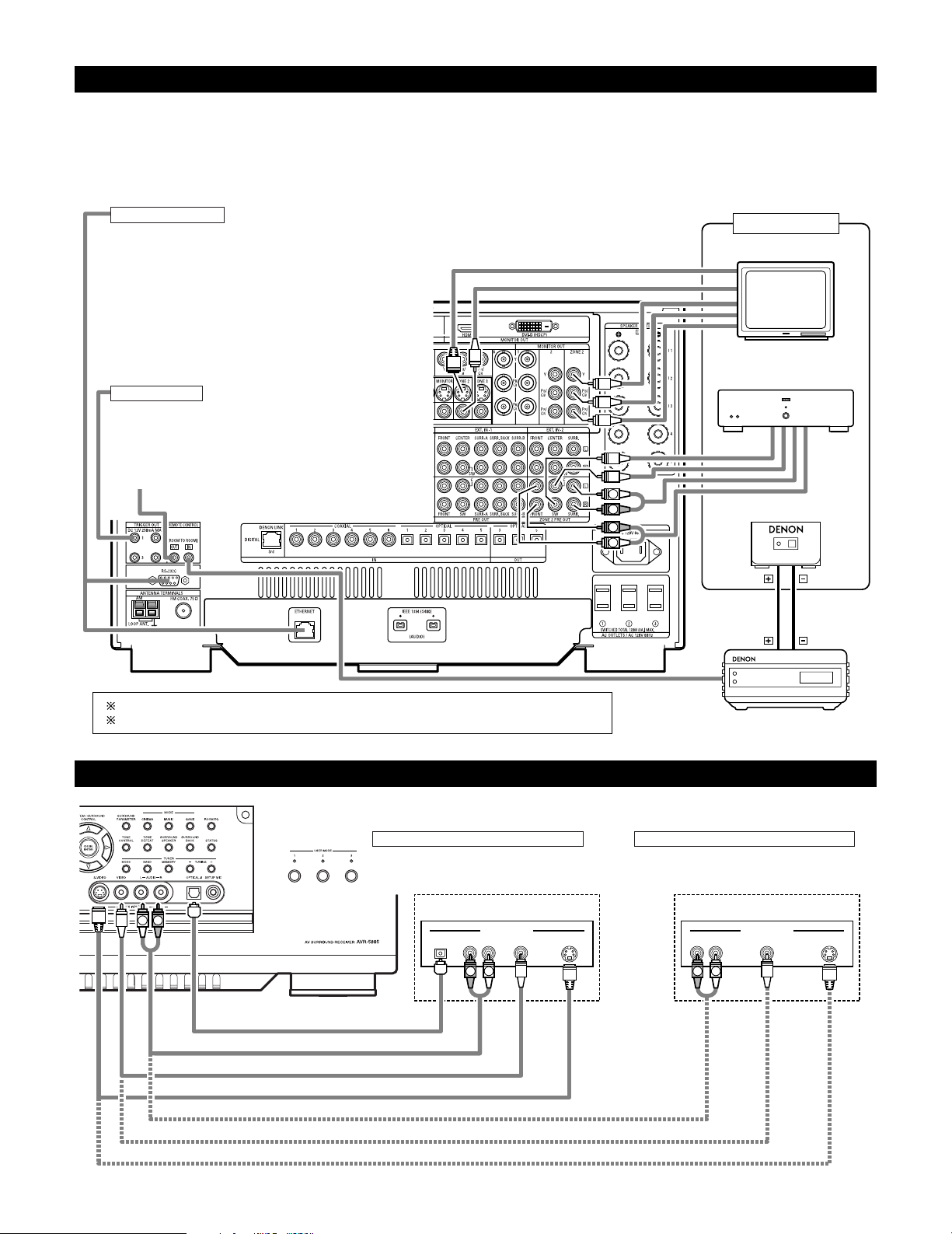
Connecting the ZONE2 jacks
L
R
R
L
OUTPUT
INPUT
AUX OUT
Another room
RC-616
INFRARED RETRANSMITTER
Power amplifier
RC-617
INFRARED SENSOR
Extension jacks for future use.
For instructions on operations using the MULTI ZONE jacks, see pages 151~165.
See pages 155, 156 for the connection method of Zone3 and Zone4.
Connecting a component with video and audio jacks to the V.AUX input jacks
•To connect the video signal, connect using a 75 Ω/ohms video signal cable cord.
R VIDEO OUT S-VIDEO OUTOPTICAL L
OUTPUT
R VIDEO OUT S-VIDEO OUTL
OUTPUT
LINE OUT
VIDEO OUT
S-VIDEO OUT
LINE OUT
DIGITAL OUT
VIDEO OUT
S-VIDEO OUT
L R
R
L
R
L
Connecting a Video game component
• Connect the Video game component’s output
jacks to this unit’s V. AUX INPUT jacks.
Video game Video camera
Connecting a video camera component
• Connect the video camera component’s output
jacks to this unit’s V. AUX INPUT jacks.
TRIGGER OUT
Turn the DC 12V voltage on and off for the individual functions
and surround modes.
For details, see “Setting the Trigger Out”. (See pages 107, 108)
CONTROL terminal
These terminals are used for an exteral controller.
Perform the following operation before using an external
controller connected to the RS-232C terminal:
1. Press the ON/STANDBY button on the main unit and set
the unit to the operating mode.
2. Perform the operation to turn off the power from the
external control.
3. Check that the product has been set to the standby
mode.
After checking the above, check the connections of the
external controller. Operation is possible.
TV
2 ZONE2 preout CONNECTIONS
• If another power amplifier or pre-main (integrated) amplifier is connected, the Zone2 preout (variable level) jacks can be used to play a different
program source in Zone2 the same time. (See page 152)
• The Zone2 video out is only use for the Zone2.
• The connection diagram below is an example of multi-channel playback in Zone2. Please see page 154 when you would like to have 2-channel
playback in Zone2.
Page 18
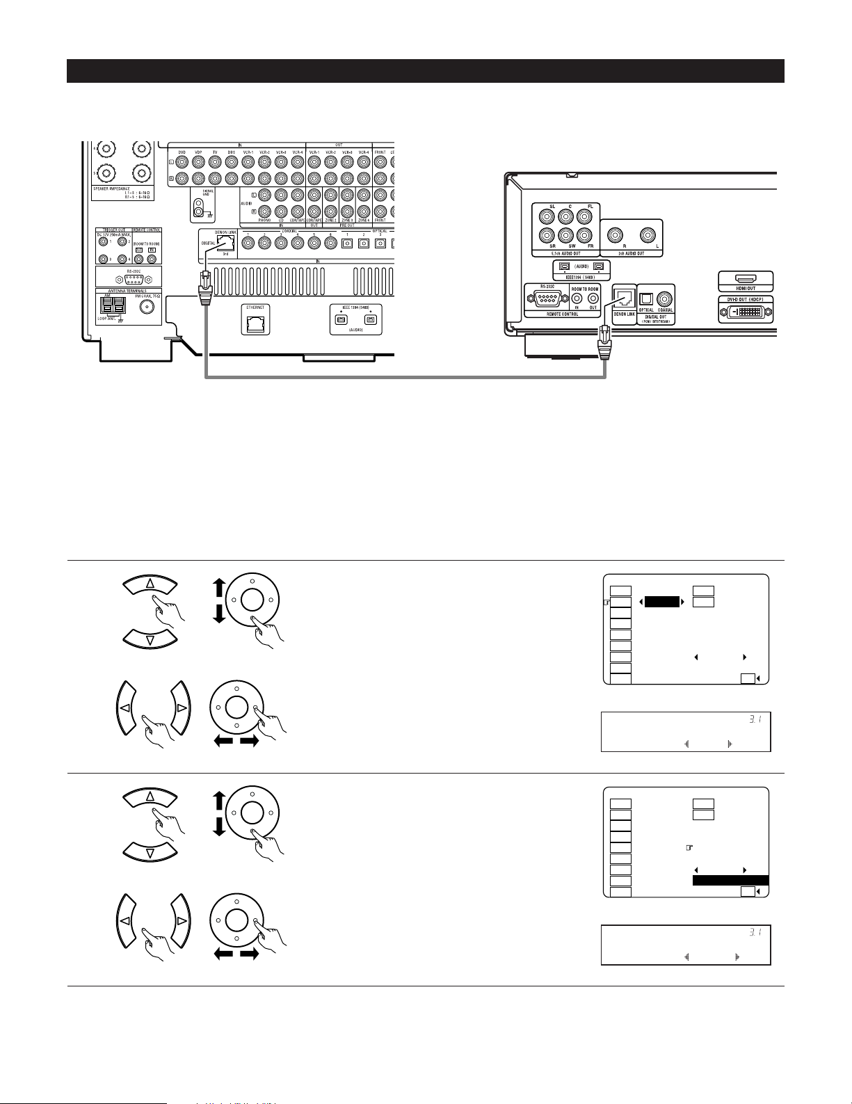
18
2 DENON LINK Setting
When a DENON DVD player and the DENON LINK have been connected, be sure to make a setting to “DENON LINK” with the System Setup
Digital In Assignment. (See pages 58, 59)
• When the input mode is AUTO and the signals are not be able to transferred by DENON LINK, the unit automatically changes over the input
to the selected signals (ANALOG, EXT. IN or IEEE1394).
1
Assign DENON LINK to the input source.
q Select the input source.
3−1.Digital In Assign
: DLINK : OPT6
: COAX3
: COAX4
: COAX5 DLINK
: OPT1 No Signal
: OPT2 EXT−1
: OPT3
: OPT4 Default
: COAX1 : OPT5
Ye s
CD Tape
DVD V.Aux
VDP
TV
DBS
VCR-1
VCR-2
VCR-3
VCR-4
2
3−1.Digital In Assign
: DLINK : OPT6
: COAX3
: COAX4
: COAX5 DLINK
: OPT1 No Signal
: OPT2 I1
: OPT3 DVD−3910
: OPT4 Default
: COAX1 : OPT5
Ye s
CD Tape
DVD V.Aux
VDP
TV
DBS
VCR-1
VCR-2
VCR-3
VCR-4
CH SEL
ENTER
2 Playback using the DENON LINK connector
Digital transfer and multi-channel playback of DVD audio discs and other multi-channel sources is possible by connecting the AVR-5805 to a
DENON DVD player equipped with a DENON LINK connector using the connection cable included with the DVD player.
CH SEL
ENTER
w Select “DLINK”.
CH SEL
ENTER
CH SEL
ENTER
w Select input signal (ANALOG, EXT.IN or IEEE1394).
DVD : DLINK
*Digital In
NoSig.: I1
*Digital In
(Main unit) (Remote control unit)
(Main unit) (Remote control unit)
(Main unit) (Remote control unit)
(Main unit) (Remote control unit)
DENON LINK connections
• High quality digital sound with reduced digital signal transfer loss can be enjoyed by connecting a separately sold DENON LINK compatible DVD
Player.
DVD player
Select the input for the playback of signals that cannot
be transferred by DENON LINK.
q Select “DLINK” setting.
Page 19
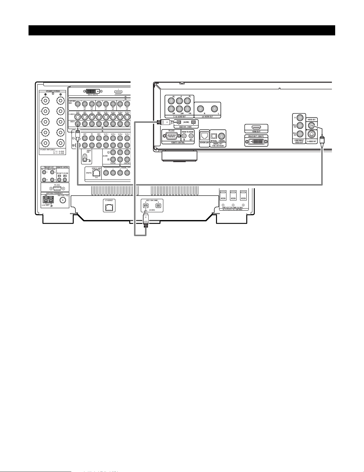
19
2 IEEE1394 network
q Up to 17 devices can be connected using daisy chain type connections.
w Up to 63 devices can be connected using tree type connections.
Do not loop the connections.
e Select IEEE 1394 input. “LINK CHECK” will be displayed while the IEEE 1394 connection is being checked.
r If the connection is looped, “LOOP CONNECT” is displayed. Check the connections and undo the loop.
Connecting IEEE1394 devices
• Use an S400-compatible 4-pin IEEE1394 cable to connect.
•Video signals are not transferred with the AVR-5805’s IEEE1394 interface, so when connecting a video device connect the video signals as
well.
• Assign the IEEE1394 input the input source. (See page 65)
DVD player
Page 20
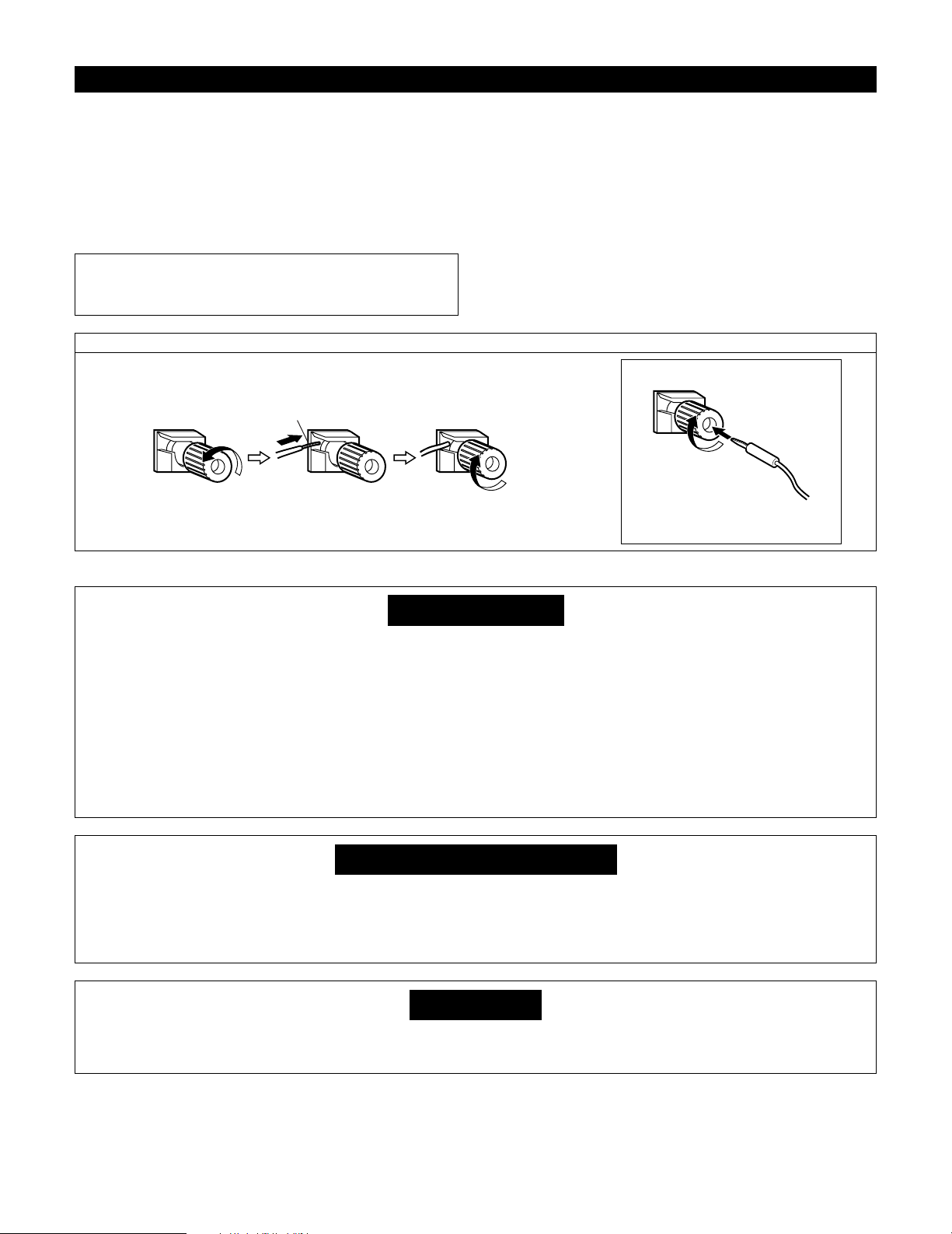
20
Speaker system connections
• Connect the speaker terminals with the speakers making sure that
like polarities are matched (< with < , > with >). Mismatching of
polarities will result in weak central sound, unclear orientation of
the various instruments, and the sense of direction of the stereo
being impaired.
• When making connections, take care that none of the individual
conductors of the speaker cord come in contact with adjacent
terminals, with other speaker cord conductors, or with the rear
panel.
Speaker Impedance
• Speakers with an impedance from 6 to 16 Ω/ohms can be
connected.
•The protector circuit may be activated if the set is played for long
periods of time at high volumes when speakers with an impedance
lower than the specified impedance are connected.
NOTE:
NEVER touch the speaker terminals when the power is on.
Doing so could result in electric shocks.
Connecting the speaker cords
1. Loosen by turning
counterclockwise.
2. Insert the cord. 3. Tighten by turning
clockwise.
Either tightly twist or terminate the core wires.
Connecting banana plugs
Turn clockwise to tighten, then insert the
banana plug.
Protector circuit
• This unit is equipped with a high-speed protection circuit. The purpose of this circuit is to protect the speakers under
circumstances such as when the output of the power amplifier is inadvertently short-circuited and a large current flows,
when the temperature surrounding the unit becomes unusually high, or when the unit is used at high output over a long
period which results in an extreme temperature rise.
When the protection circuit is activated, the speaker output is cut off and the power supply indicator LED flashes. Should
this occur, please follow these steps: be sure to switch off the power of this unit, check whether there are any faults
with the wiring of the speaker cables or input cables, and wait for the unit to cool down if it is very hot. Improve the
ventilation condition around the unit and switch the power back on.
If the protection circuit is activated again even though there are no problems with the wiring or the ventilation around the
unit, switch off the power and contact a DENON service center.
Note on speaker impedance
• The protector circuit may be activated if the set is played for long periods of time at high volumes when speakers with
an impedance lower than the specified impedance (for example speakers with an impedance of lower than 4 Ω/ohms)
are connected. If the protector circuit is activated, the speaker output is cut off. Turn off the set’s power, wait for the set
to cool down, improve the ventilation around the set, then turn the power back on.
Cooling fan
• The AVR-5805 is equipped with a cooling fan to prevent the temperature inside the set from rising. The fan is activated
under certain usage conditions. It is temperature sensitive, to minimize or prevent audible fan noise.
Page 21
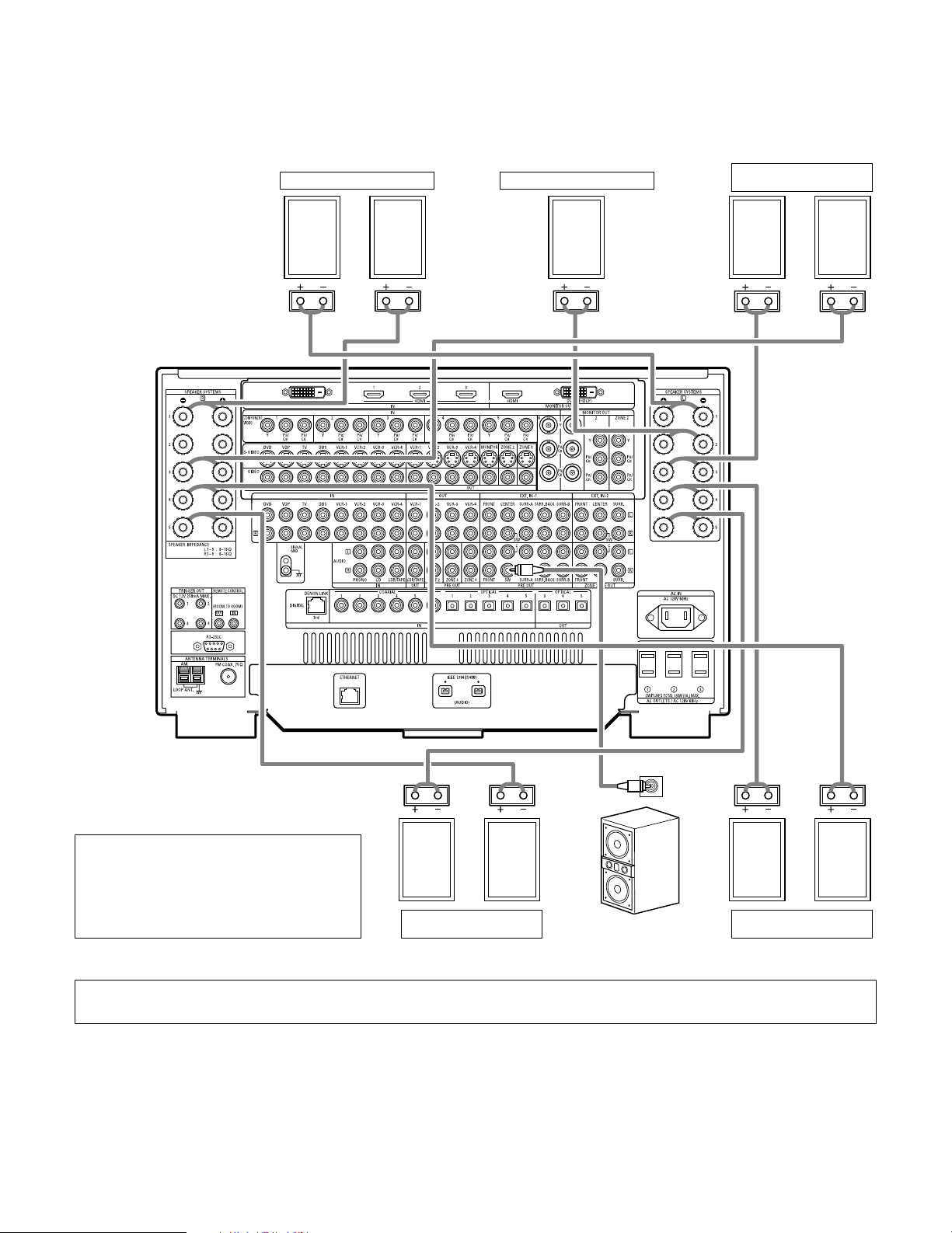
21
Connections
• By default, the speaker system setting is set to 9.1 channels.
• The output of each power amplifier can be assigned to any desired channel to best suit the application.
For details, refer to “Setting the Channel Setup” and “Setting the Power Amplifier Assignment”. (See pages 97~105)
• When making connections, also refer to the operating instructions of the other components.
IN
(L) (L) (R) (R)
(L) (R) (L) (R)
Connection jack for
subwoofer with built-in
amplifier (subwoofer), etc.
SURROUND SPEAKER
SYSTEMS (A)
CENTER SPEAKER SYSTEMFRONT SPEAKER SYSTEMS
• Precautions when connecting speakers
If a speaker is placed near a TV or video monitor, the
colors on the screen may be disturbed by the
speaker’s magnetism. If this should happen, move
the speaker away to a position where it does not
have this effect.
SURROUND SPEAKER
SYSTEMS (B)
SURROUND BACK
SPEAKER SYSTEMS
NOTE:
• When using only one surround back speaker, connect it to left channel (L5).
Page 22
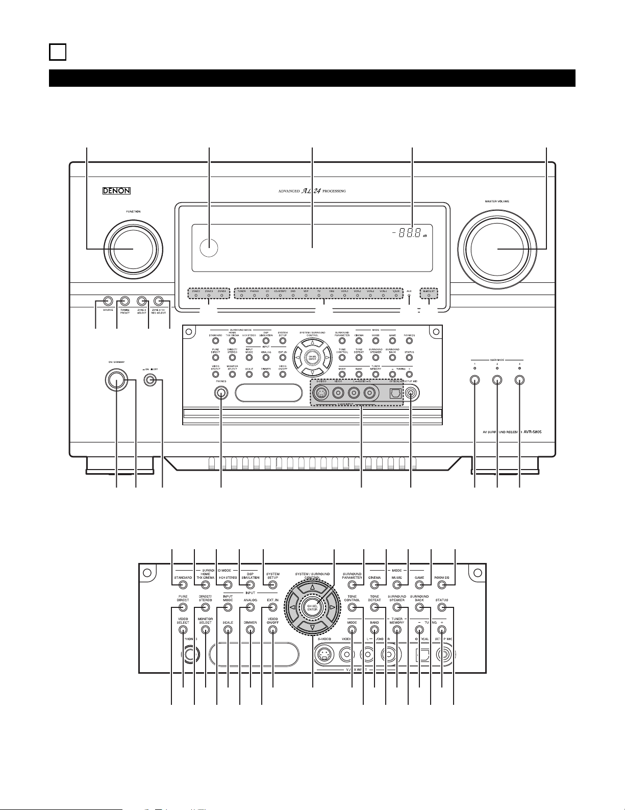
22
6
PART NAMES AND FUNCTIONS
Front Panel
• For details on the functions of these parts, refer to the pages given in parentheses ( ).
!4 !3 !2 !1 !0
q w e r t y u i o
!5 !6 !7 !8
!9
@0
@1%4
#8 $0 $2 $3#6
#5#3 #7 #9 $1
#4 $8$6$4 %0
%1 %3$9$7$5
%2
@3@2 @4 @5 @6 @9@8@7 #0 #1 #2
Page 23

23
q
Power ON/STANDBY switch.................................................(125)
w
Power indicator......................................................................(125)
e
Power switch.................................................................(125, 173)
r
Headphones jack (PHONES)..................................................(130)
t
V.AUX INPUT jacks ..................................................................(17)
y
SETUP MIC jack ......................................................................(32)
u
USER MODE 1 button...........................................................(146)
i
USER MODE 2 button...........................................................(146)
o
USER MODE 3 button...........................................................(146)
!0
MASTER VOLUME control....................................................(127)
!1
Master volume indicator........................................................(127)
!2
Display
!3
Remote control sensor ..........................................................(113)
!4
FUNCTION knob ...................................(126, 132, 133, 157, 168)
!5
SOURCE button.....................................................................(126)
!6
TUNING PRESET button........................................................(168)
!7
ZONE2 SELECT button..........................................................(157)
!8
ZONE3/4/REC SELECT button ..............................(132, 133, 157)
!9
Multi Zone power indicators..................................................(158)
@0
Input source indicators ..........................................................(126)
@1
MultEQ XT indicator ..............................................................(130)
@2
STANDARD button........................................................(140~144)
@3
HOME THX CINEMA button .........................................(137, 139)
@4
9CH STEREO button .............................................................(148)
@5
DSP SIMULATION button .....................................................(148)
@6
SYSTEM SETUP button...........................................................(26)
@7
CH SELECT/ENTER button......................................(26, 134, 135)
@8
SURROUND PARAMETER button.........................................(137)
@9
CINEMA button .............................................................(142, 144)
#0
MUSIC button................................................................(142, 144)
#1
GAME button.........................................................................(142)
#2
ROOM EQ button..................................................................(130)
#3
PURE DIRECT button ............................................................(129)
#4
VIDEO SELECT button ..........................................................(130)
#5
DIRECT/STEREO button........................................................(129)
#6
MONITOR SELECT button ....................................................(131)
#7
INPUT MODE button.............................................................(126)
#8
SCALE button ........................................................................(132)
#9
ANALOG button.....................................................................(126)
$0
DIMMER button ....................................................................(131)
$1
EXT.IN button.................................................................(126, 128)
$2
VIDEO ON/OFF button ..........................................................(129)
$3
CURSOR button.......................................................................(26)
$4
MODE button ................................................................(165, 166)
$5
TONE CONTROL button........................................................(150)
$6
BAND button .................................................................(165, 166)
$7
TONE DEFEAT button ...........................................................(150)
$8
MEMORY button...................................................................(167)
$9
SURROUND SPEAKER button ..............................................(131)
%0
TUNING down (–) button...............................................(165, 166)
%1
SURROUND BACK button.............................................(139, 140)
%2
TUNING up (+) button ...................................................(165, 166)
%3
STATUS button ......................................................................(131)
%4
Extension indicator for future use
Page 24
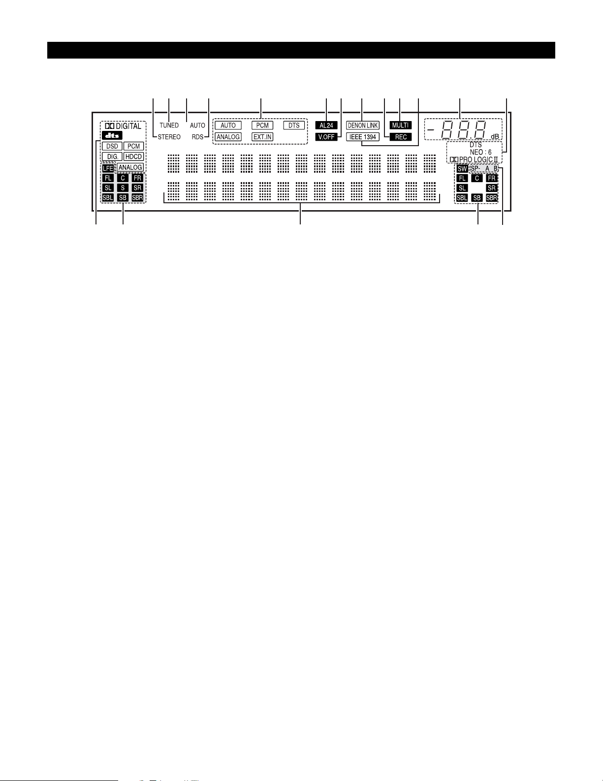
24
Display
u yo!0!1!3!2!4!6!7!8 !5 i
e
r t
q
w
q
INPUT SIGNAL indicator
The respective indicator will light corresponding to the input
signal.
w
INPUT SIGNAL CHANNEL indicator
The channels included in the input source will light.
This lights when the digital signal is inputted.
e
Information display
This displays the surround mode, function name or setting
value, etc.
r
OUTPUT SIGNAL CHANNEL indicator
The audio channels output from this unit will light.
t
SPEAKER indicator
This lights corresponding to the settings of the surround
speakers of the various surround modes.
y
Decoder indicator
This lights when each decoder is operating.
u
MASTER VOLUME indicator
This displays the volume level.
The Setup item number is displayed in System Setup.
i
IEEE1394 indicator
This lights during playback in a IEEE1394 connection.
o
MULTI (ZONE) indicator
ZONE3 mode is selected in ZONE3/REC SELECT.
!0
REC OUT SOURCE indicator.
REC OUT mode is selected in ZONE3/REC SELECT.
!1
DENON LINK indicator
This lights during playback in a DENON LINK connection.
!2
V.OFF indicator
This lights when the operation of the video circuit has been
turned off.
!3
AL24 indicator
The AL24 indicator lights when the PURE DIRECT, DIRECT,
STEREO, MULTI CH PURE DIRECT , MULTI CH DIRECT, MULTI
CH IN mode is selected in the PCM input signal.
!4
INPUT MODE indicator
This lights corresponding to the setting of the INPUT mode.
!5
RDS indicator
This lights when RDS broadcast has been received.
!6
AUTO indicator
This lights when the broadcast station is selected in the AUTO
tuning mode.
!7
TUNED indicator
This lights when an FM/AM broadcast has been received.
!8
STEREO indicator
This lights when an FM stereo broadcast has been received.
Page 25
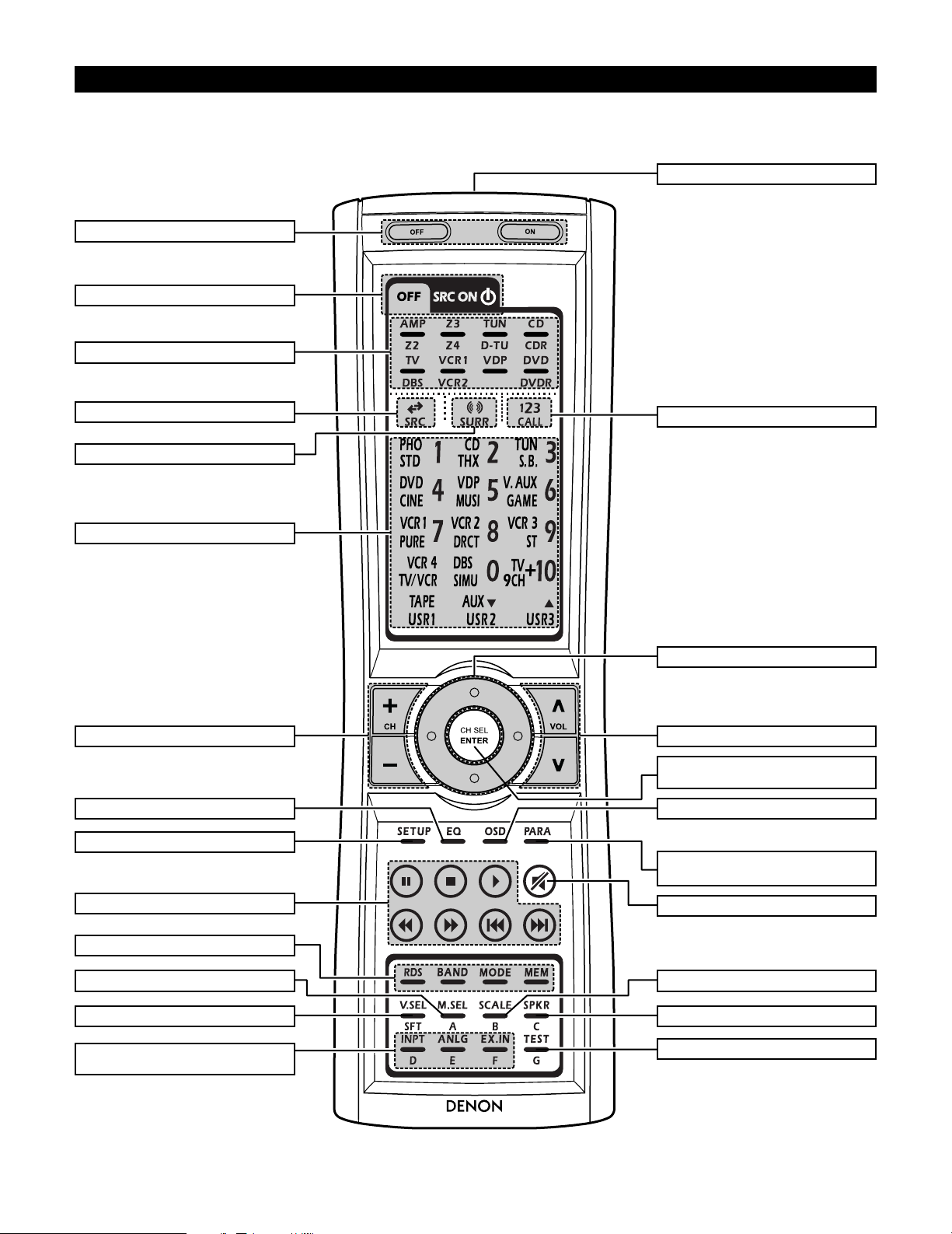
25
RC-995
Remote control unit
• For details on the functions of these parts, refer to the pages given in parentheses ( ).
Cursor buttons........................................(26)
Power buttons......................................(125)
10KEY/SYSTEM CALL button ..............(114)
SURROUND PARAMETER button
.....................................................(137, 162)
Master volume control buttons....(127, 158)
ON SCREEN button .............(131, 138, 158)
INPUT MODE selector buttons
.............................................(126~128, 158)
VIDEO SELECT button.................(130, 158)
Tuner system buttons..................(167~172)
SYSTEM buttons..........................(114, 115)
Input source button..............................(114)
Mode selector buttons.........................(114)
Remote control signal transmitter........(113)
SYSTEM buttons..................................(158)
MUTING button............................(130, 158)
Surround mode button .........................(114)
SYSTEM SETUP button .................(26, 159)
ROOM EQ button ................................(130)
CH SELECT/ENTER button
...............................(26, 134, 135, 160, 161)
SCALE button.......................................(132)
SPEAKER button ..................................(131)
TEST TONE button.......................(134, 159)
MONITOR SELECT button...................(131)
Tuner system buttons..................(165~173)
SYSTEM buttons..........(114, 115, 117, 118)
Page 26
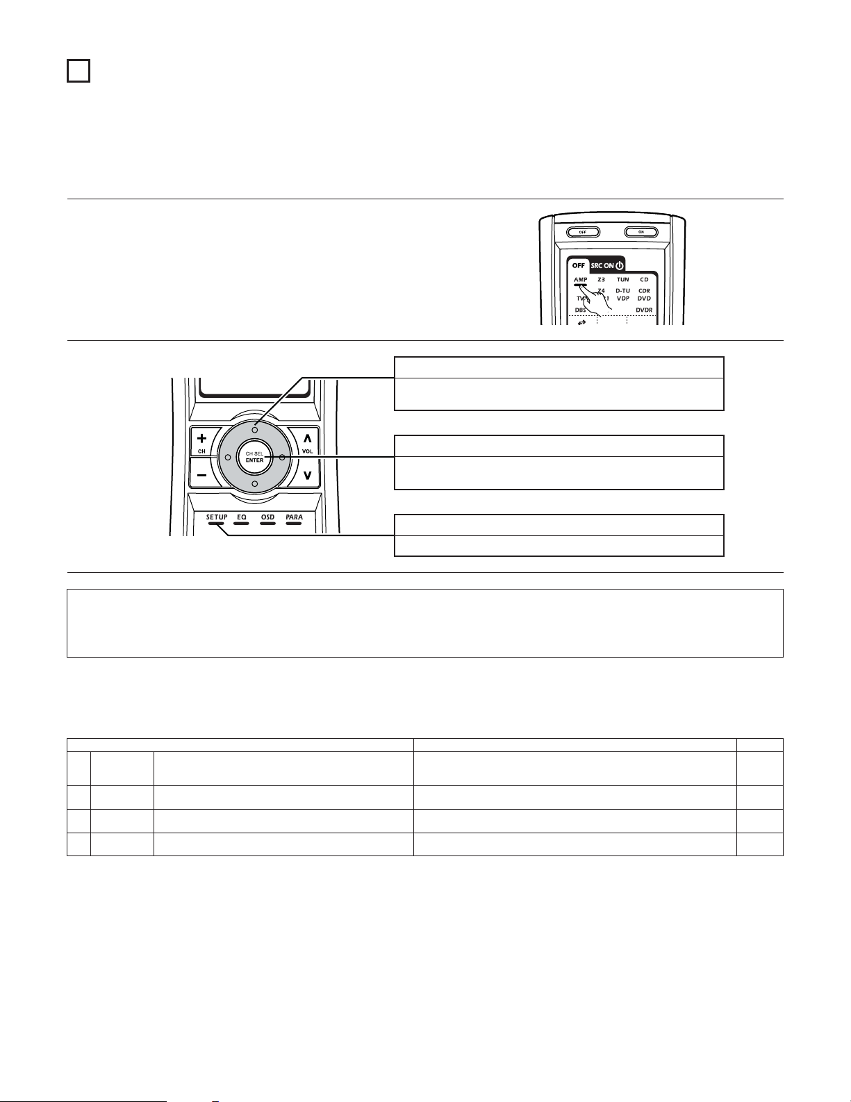
26
7
SYSTEM SETUP
• Once all connections with other AV components have been completed as described in “CONNECTIONS” (see pages 9~21), make the various
settings described below on the monitor screen using the AVR-5805’s on-screen display function.
These settings are required to set up the listening room’s AV system centered around the AVR-5805.
SYSTEM SETUP button
Press this to display the system setup menu.
ENTER button
Press this to switch the display.
Also use this button to complete the setting.
CURSOR buttons
Use these to move the cursors the left, right, up and down on
the screen.
1
Check that the remote control unit set to AMP mode.
2
2 Use the following buttons to set up the system
2 System setup items and default values (set upon shipment from the factory)
1. Auto Setup/Room EQ
Auto Setup / Room EQ Default settings
1
Auto Setup
Room EQ
Setup
2
Direct Mode
Setup
4
Set the ON/OFF setting of Room EQ, in the case of the surround
mode is in Direct or Pure Direct.
3
Mic Input
Select
Set this to switch the Mic Input jack for use for Mic or V.AUX Lchannel input jack.
This unit performs an analysis of the speaker system and measures
the acoustic characteristics of your room to permit an appropriate
automatic setting.
Set the Room EQ setting with All or Assign for each surround mode.
–
All, Room EQ = OFF
OFF
Mic
Page
33~39
40, 41
41
42, 43
NOTES:
• The AVR-5805’s on-screen display function is designed for use with high resolution monitor TVs, so it may be difficult to read small
characters on TVs with small screens or low resolutions.
• The setup menu is not displayed when headphones are being used.
Page 27
27
3. Audio Input Setup
Audio Input Setup Default settings Page
58, 59
Digital In
Assign
This assigns the digital input jacks for the different input
sources.
Input
source
Digital
Inputs
CD DVD VDP TV DBS VCR-1 VCR-2
COAX 1 COAX 2 COAX 3 COAX 4 COAX 5 OPT 1
OPT 2
1
CDR/TAPE
OPT 5
VCR-3 VCR-4
OPT 3 OPT 4
V.AUX
OPT 6
2
EXT.IN Setup Set the Ext.In terminal playback method.
EXT.IN-1
Setup
EXT.IN-2
Setup
Mode = DSP, Surr.B = NOT USED, S.Back = NOT USED,
SW Level = +15 dB, Input ATT. = OFF
Mode = DSP, SW Level = +15 dB, Input ATT. = OFF
62
Input Function
Lev.
The playback level is corrected individually for the different input
sources.
TUNER PHONO CD
CDR/
TAPE
DVD VDP TV
0 dB 0 dB 0 dB 0 dB 0 dB 0 dB 0 dB
3
VCR-2
0 dB
DBS VCR-1
0 dB 0 dB
VCR-3
0 dB
VCR-4
0 dB
V.AUX
0 dB
4
Function
Rename
The names of the different input source can be changed as desired
and displayed on the display.
63, 64
5
IEEE1394
Assign
The connected IEEE1394 device can be automatically identified to
assign the input source.
–65
6
IEEE1394
Auto Func.
Set the function for associating playback of the connected IEEE1394
device on or off.
Auto Function = OFF 66
7
Tuner Presets
FM stations are received automatically and stored in the
memory.
A1 ~ A8
B1 ~B8
C1 ~C8
D1 ~D8
E1 ~E8
87.5/89.1/98.1/107.9/90.1/90.1/90.1/90.1 MHz
520/600/1000/1400/1500/1710 kHz, 90.1/90.1 MHz
90.1 MHz
90.1 MHz
90.1 MHz
Auto
Preset
Memory
F1 ~F8
G1 ~G8
90.1 MHz
90.1 MHz
Preset channels that are not used often can be skipped.
Preset
Skip
The preset channels can be given the names you want.
Preset
Name
67
All preset channels = OFF 68
– 69, 70
60, 61
TUNER PHONO CD
CDR/
TAPE
DVD VDP TV
VCR-2DBS VCR-1 VCR-3 VCR-4 V.AUX
2. Speaker Setup
Speaker Setup Default settings
1
3
Speaker
Configuration
Channel Level
Input the combination of speakers in your system and their
corresponding sizes (SMALL for regular speakers, LARGE for fullsize, full-range) to automatically set the composition of the signals
output from the speakers and the frequency response.
This adjusts the volume of the signals output from the speakers and
subwoofer for the different channels in order to obtain optimum
effects.
Front Sp.
Small
Center Sp.
Surround Sp.
A / B
Subwoofer
Small SmallYe s
Front L & R Center
Surround
L & R (A)
Subwoofer
12 ft (3.6 m) 12 ft (3.6 m) 10 ft (3.0 m)12 ft (3.6 m)
Front L Front R Center
Surround
R (A)
Surround
R (B)
Subwoofer
0 dB 0 dB 0 dB 0 dB
0 dB
0 dB
Surround Back
Sp.
Small / 2spkrs
4
Delay Time
This parameter is for optimizing the timing with which the audio
signals are produced from the speakers and subwoofer according to
the listening position.
Surround
L & R (B)
10 ft (3.0 m)
Surround
L (B)
0 dB
Surround
L (A)
0 dB
Crossover
Frequency
Set the frequency (Hz) below which the bass sound of the various
speakers is to be output from the subwoofer.
5
FIXED —THX—
Page
46, 47
2
Subwoofer
Setup
This selects the subwoofer for playing deep bass signals. LFE —THX— 48
49, 50
51, 52
53, 54
Surround
Speaker Setup
Use this function when using multiple surround speaker
combinations for more ideal surround sound. Once the
combinations of surround speakers to be used for the
different surround modes are preset, the surround
speakers are selected automatically according to the
surround mode.
Surround
mode
Surround
speaker
THX/DOLBY/
DTS
CINEMA
THX/DOLBY/
DTS
MUSIC
WIDE
SCREEN
9 CH
STEREO
DSP
SIMULATION
MULTI CH
MODE
AAAA+B A+B A+B A
6
THX/DOLBY
GAME
55
7
THX Audio
Setup
When using a THX Ultra2 compatible subwoofer,
set the subwoofer’s frequency response.
THX Ultra2 Subwoofer = NO
Boundary Gain
compensation
Surround Back
Speaker Position
When using two surround back speakers, set
the distance of the two speakers.
The Distance Between SBL/SBR = 0 ft to 1 ft (0 m to 0.3 m)
56
Surround
Back
10 ft (3.0 m)
Surround
Back R
0 dB
Surround
Back L
0 dB
4. Video Setup
Video Setup Default settings
1
3
Component In
Assign
HDMI/DVI In
Assign
This assigns the color difference (component) video input jacks for
the different input sources.
The HDMI or DVI input terminals are assigned for the different input
sources.
Select HDMI or DVI for the monitor output terminal.
Select the HDMI audio signal playback method.
DVD VDP TV
5
Video Scaler
Make the settings related to video output (resolution and aspect rate
conversion).
Audio Delay Set the audio delay timing to synchronize the sound and video.
6
0 ms
Page
71, 72
2
Video Convert
Mode
Set the input signal to be output from the monitor output terminal. AUTO 72, 73
73, 74
75, 76
76, 77
On Screen
Display
This sets whether or not to display the on-screen display that
appears on the monitor screen when the controls on the remote
control unit or main unit are operated.
7
Function/Mode = ON, Master Volume = ON, Mode = Mode 1 77, 78
DBS VCR-1 VCR-2 VCR-3 VCR-4 V.AUX
1-RCA 2-RCA 3-RCA 4-RCA 5-RCA 6-BNC NONE NONE NONE
Aspect = FULL, Resolution = 480i / 576i
DVD VDP TV
DBS VCR-1 VCR-2 VCR-3 VCR-4 V.AUX
NONE NONE NONE NONE NONE NONE NONE NONE NONE
4
3D Y/C
Separation
This setting sets the action detection sensitivity of the 3-dimensional
Y/C separation at the time of the video signal up-conversion to SVideo.
74Motion Detection = MID
57
Page 28

28
6. Zone Setup
Zone Setup Default settings
1
3
Speaker
Configuration
Channel Level
The components of the signals output from the various speakers and
the frequency response can be set automatically inside the set by
inputting the existence/absence of combinations of speakers and
their size (corresponding to their low frequency playback capability)
for the speakers used in Zone2 during surround playback in Zone2.
This adjusts the volume of the signal output from the various
speakers and subwoofer used in Zone2.
Front Sp.
Small
Center Sp. Surround Sp.Subwoofer
Small SmallYes
Front L & R Center Surround L & RSubwoofer
12 ft (3.6 m) 12 ft (3.6 m) 10 ft (3.0 m)12 ft (3.6 m)
Front L Front R Center Surround R Subwoofer
0.0 dB 0.0 dB 0.0 dB 0.0 dB 0.0 dB
4
Delay Time
This parameter is for optimizing the timing of the sound produced
from the various speakers and subwoofer according to the listening
position in Zone2.
Surround L
0.0 dB
Crossover
Frequency
Set the frequency (in Hz) below which deep bass appearing in the
main channels will be routed to the Zone2 subwoofer.
5
80 Hz
Page
86
2
Subwoofer
Mode
This selects the subwoofer used in Zone2 for playing the low base
sound.
LFE 87
88, 89
90, 91
92
Video Setup
Set the input signal to be output from the Zone2
monitor out terminal.
Video
Convert
Mode
Audio Delay
6
93, 94
7
Zone3/4
Tone/Ch.Lev.
Adjust the tone and channel level of the sound output
from Zone3 and Zone4.
Bass = 0 dB, Treble = 0 dB, HPF = OFF, L/R = 0 dB
95, 96
Set the delay time the sound is synchronized with the
picture which are outputted in Zone2.
AUTO
0 ms 94
Zone3
Zone4
Bass = 0 dB, Treble = 0 dB, HPF = OFF, L/R = 0 dB
5. Advanced Playback
Advanced Playback Default settings
1
2
2ch
Direct/Stereo
Auto Surround
Mode
Turn the audio compression on or off when down-mixing Dolby
Digital signals.
3
Dolby Digital
Setup
The speaker settings can be changed specifically for playing in the 2channel direct or stereo mode.
Set the Auto surround mode function.
Basic
OFF
Auto Surround Mode = ON
Page
79
80
81
7. Option Setup
Option Setup Default settings
1
3
Channel Setup
Trigger Out
Setup
The number of channels that you wish to play back in each zone are
assigned to each zone accordingly.
This sets the Trigger Out output for the different input
sources.
If “Zone=Main” is selected, settings can be made for
the individual surround modes.
Main Zone
9.1 CH
Zone2 Zone4Zone3
5.1 CH StereoStereo
4
Volume
Control
AC Outlet
Assign
This sets the AC outlets to on or off for the different
input sources.
5
Page
97~100
2
Power Amp
Assign
Power Amplifiers can be assigned to the various channels according
to your system’s requirements.
Normal
101~105
107, 108
6
Setup
Memory/Lock
–110, 111
L1FLL2CL3
SLAL4SLBL5SBLR1FRR2–R3SRAR4SRBR5SBR
This sets the volume level of each zone output.
Volume Limit: This sets the upper limit for the
master volume.
Power On Level: This sets the volume level upon
switching on the power of each
zone.
Mute Level: This sets the amount of attenuation
of the audio output when each
zone is muted.
Volume Level: This se ts whether the output level
of Zone2 to 4 is fixed or variable.
106, 107
Vol.Limit = OFF, P. On Lev. = LAST, Mute Lev. = FULL
Vol.Lev. = VAR, Vol.Limit = OFF, P. On Lev. = LAST, Mute Lev. = FULL
Vol.Lev. = VAR, Vol.Limit = OFF, P. On Lev. = LAST, Mute Lev. = FULL
Vol.Lev. = VAR, Vol.Limit = OFF, P. On Lev. = LAST, Mute Lev. = FULL
Trigger
Out 1
ZONE = MAIN, All Surround Modes = ON
TUNER PHONO CD
CDR/
TAPE
DVD VDP TV
OFF OFF OFF OFF ON ON ON
VCR-2
ON
DBS VCR-1
ON ON
VCR-3ONVCR-4ONV.AUX
ON
Trigger
Out 2
ZONE = 2
TUNER PHONO CD
CDR/
TAPE
DVD VDP TV
ON ON ON ON ON ON ON
VCR-2
ON
DBS VCR-1
ON ON
VCR-3ONVCR-4ONV.AUX
ON
Trigger
Out 3
ZONE = 3
TUNER PHONO CD
CDR/
TAPE
DVD VDP TV
ON ON ON ON ON ON ON
VCR-2
ON
DBS VCR-1
ON ON
VCR-3ONVCR-4ONV.AUX
ON
Trigger
Out 4
ZONE = 4
TUNER PHONO CD
CDR/
TAPE
DVD VDP TV
ON ON ON ON ON ON ON
VCR-2
ON
DBS VCR-1
ON ON
VCR-3ONVCR-4ONV.AUX
ON
109, 110
AC Outlet
1~3
ZONE = MAIN
TUNER PHONO CD
CDR/
TAPE
DVD VDP TV
ON ON ON ON ON ON ON
VCR-2
ON
DBS VCR-1
ON ON
VCR-3ONVCR-4ONV.AUX
ON
This stores the current user settings in the memory.
User
Memory
This sets whether or not to lock the system setup
settings so that thay cannot be changed.
Setup
Lock
Setup Lock = OFF
MAIN
ZONE2
ZONE3
ZONE4
111, 112
4
This parameter is for optimizing the Room EQ with which the audio
signals are produced from the speakers.
Manual EQ
Setup
All Channels and Frequency=0dB 82~84
Page 29
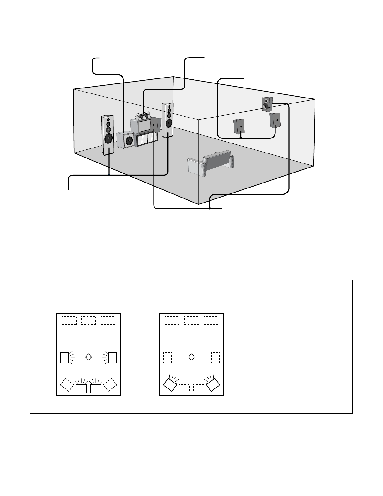
29
2 Speaker system layout
Basic system layout (For a THX Ultra2 system)
• The following is an example of the basic layout for a system consisting of eight speaker systems and a television monitor:
Subwoofer Center speaker system
Surround speaker systems
Surround back speaker systems
Front speaker systems
Set these at the sides of the TV or screen with
their front surfaces as flush with the front of the
screen as possible.
• Surround speaker selector function
This function makes it possible to achieve the optimum sound fields for different sources by switching between two systems of surround
speakers (A and B). The settings of the different speakers (A only, B only or A+B) are stored in the memory for the different surround
modes, so they are set automatically when the surround mode is selected.
AA
BB
AA
BB
SB SB SB SB
Using A only
(Multi surround speaker system)
Using B only
(Single surround speaker system)
(SB: Surround Back Speakers)
Two surround back speakers are required to use the THX Ultra2 Cinema,THX Music mode and THX Games mode.
Set the surround back speakers so that the distance to the listening position is the same for both the left and right speakers. It is also
recommended that the deviations of the distance from the listening position to L and R channel speakers (front left (FL) and front right (FR),
surround left (SL) and surround right (SR), surround back left (SBL) and surround back right (SBR)) is less than 2 ft (60 cm).
With the AVR-5805 it is also possible to use the surround speaker selector function to choose the best layout for a variety of sources and surround
modes.
Page 30
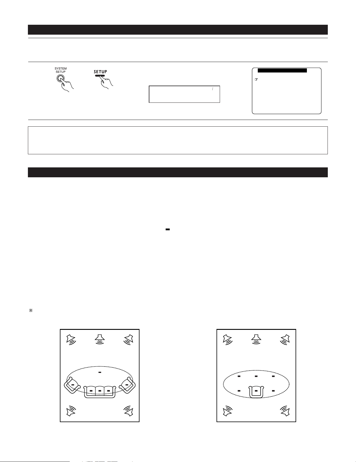
Example w:
*
M
30
Before setting up the system
1
2
Check that all the connections are correct, then turn on the main unit’s power.
Setup will not be possible when the unit is set to Pure Direct ON, the Video Off mode, or when the headphones are plugged in. Therefore,
please cancel the mode or reverse the condition.
Display the System Setup Menu.
1.Auto Setup/Room EQ
2.Speaker Setup
3.Audio Input Setup
4.Video Setup
5.Advanced Playback
6.Zone Setup
7.Option Setup
Exit
System Setup Menu
(Main unit) (Remote control unit)
Auto Set/RoomEQ
*System Setup
NOTES:
• The System Setup menu composition is of a layered design that includes the related items below the large table title as contained in the
tables of pages 26~28.
• Wherever your position in System Setup, one more press of the System Setup button permits a move to one level higher.
Auto Setup / Room EQ
The Auto Setup and Room EQ function of this unit performs an analysis of the speaker system and measures the acoustic characteristics of your
room to permit an appropriate automatic setting.
The AVR-5805’s Audyssey MultEQ XT function has the feature that it provides the optimum listening environment at all listening positions in the
home theater, where there are often multiple listeners viewing programs together. To achieve this, it is first necessary to use a microphone to
measure test tones generated from the different speakers at the various listening positions. All this measured data is analyzed with a unique
method to comprehensively improve acoustic characteristics in the listening area. For optimum effectiveness, measurements should be
performed at six or more points. Move the microphone successively within the listening area surrounded by the speakers as shown on the
diagram below to measure the test tones. When listening to music or viewing movies with the whole family, move the microphone successively
to the different positions in which the members of the family sit (“ ” on the diagram indicates the points of installation) and measure repeatedly
(Example q). Even if the number of people using the home theater is small, taking multiple measurements at or near the listening positions makes
it possible to correct the sound more effectively (Example w).
The AVR-5805’s Room EQ function offers three correction curves: “Audyssey”, “Front” and “Flat”. These can be selected after performing the
auto setup procedure. Details of the different correction curves are described below.
Audyssey : This adjusts the frequency response of all speakers to correct the effects of room acoustics.
Front : This adjusts the characteristics of each speaker to the characteristics of the front speakers.
Flat : This the frequency response of all speakers flat.
This is suitable for multi-channel music reproduction, from discrete music sources such as Dolby Digital 5.1, DTS, DVD-Audio and
SACD.
About the main listening position (*M)
The main listening position is the point where a listener sits most often or the listening position when only one person is listening. Measurements
on the AVR-5805 start from this point. Correction for the speaker distance (“Delay Time”) is set based on this point.
When performing Auto Setup, an optional microphone is required for setup.
Example q:
*
M
Page 31

31
2 Measurement flow
I. Connect the microphone to be used for the auto setup procedure.
Please place the measuring microphone at ear height at the main listening
position.
III. Preliminary measurement items
q Measuring the background noise (noise in the room)
w Determining whether or not speakers are connected (speaker detection)
e Checking the polarities of the speakers
NOTE:
•A moderately loud test tone is output during
the measurement. Please consider this should
you be planning night time measurements, and
consider not allowing small children into the
listening time.
II. Extra Setup
q Channel Setup
w Power Amp Assign
By default, the speaker system
setting is set to 9.1 channels.
Please set under “Extra Setup”,
only when you want to change
this arrangement.
III. Check the results of the speaker detection.
IV.Speaker system measurement items
q Speaker Configuration : This sets the speaker bass reproduction ability.
w Delay Time : This sets the optimum delay time from each speaker corresponding to the listening position.
e Channel Level : This sets the volume that is output from each speaker.
r Crossover Frequency : This set the frequency (Hz) below which the bass sound of the various speakers is to be output from
the subwoofer.
t Room EQ : This sets the frequency response of each speaker.
(Main (1st) listening position)
Continue measuring ?
Select “OK Next” and put the
microphone at next point.
Quit measuring ?
Select “Calculate”.
V. Check the results of the speaker system measurements.
V. Store the measurement results in the memory.
Move the microphone to the 2nd
to 8th listening positions and
repeat the measurement.
Page 32

32
Before performing the Auto Setup procedure
1
Check again that the speakers are securely connected to the AVR-5805.
2
Set the volume to halfway and set the crossover frequency to the maximum or Low pass filter off if your subwoofer can adjust the output
volume and the crossover frequency. Some subwoofers have a standby mode. Be sure to turn this function off before performing the
Auto Setup procedure.
3
The auto setup procedure uses the OSD (on-screen display) function, so connect the AVR-5805 to a TV, projector, or other monitor.
I
. Connecting the microphone for Auto Setup
1
Connect the optional microphone for Auto Setup to the Setup Mic connector on the front panel of the unit.
NOTES:
• The optional standard microphone is DENON DM-S305 sold
separately.
• When using other microphone, see pages 42, 43.
2
Mount the auto setup microphone onto a camera tripod, etc.,
and place it at ear height at the main listening position (*) in
the listening room with the sound receptor facing the ceiling.
When placing the microphone, adjust the height so that the
microphone’s sound receptor is at the height of the ears of
the listener.
Be sure that at the beginning, the measurement is started
with the microphone set up at the main listening position.
NOTE:
• Do not disconnect the microphone until the settings are
completed.
Microphone
Page 33

33
1.Auto Setup/Room EQ
2.Speaker Setup
3.Audio Input Setup
4.Video Setup
5.Advanced Playback
6.Zone Setup
7.Option Setup
Exit
System Setup Menu
1
Select “Auto Setup / Room EQ” at the System Setup
Menu.
CH SEL
ENTER
(Main unit) (Remote control unit)
Auto Set/RoomEQ
*System Setup
2
Display the Auto Setup / Room EQ Menu screen.
CH SEL
ENTER
(Main unit) (Remote control unit)
Auto Setup
*AutoSet/RoomEQ
1.Auto Setup
2.Room EQ Setup
3.Direct Mode Setup
4.Mic Input Select
5.Parameter Check
Exit
1.Auto Setup/Room EQ
Setting the Auto Setup / Room EQ
1
1-1. Setting the Auto Setup
1.Auto Setup
2.Room EQ Setup
3.Direct Mode Setup
4.Mic Input Select
5.Parameter Check
Exit
1.Auto Setup/Room EQ
1
Select “Auto Setup” at the Auto Setup / Room EQ
Menu.
CH SEL
ENTER
(Main unit) (Remote control unit)
Auto Setup
*AutoSet/RoomEQ
2
Display the Auto Setup screen.
CH SEL
ENTER
(Main unit) (Remote control unit)
1−1.Auto Setup
at ear height at
Please place microphone
main listening position.
Cancel
Start
Channel:9.1CH
Extra Setup
Start
*Auto Setup
The message “Connect Microphone” is displayed
if no microphone is connected. If so, connect the
auto setup microphone.
Page 34

34
II
. Extra Setup
• By default, the speaker system setting is set to 9.1 channels.
Perform this setting if you want to change the channel setup to match the speaker system you are using or to conduct the power amplifier
assignment procedure. If you do not want to perform this “Extra Setup” procedure, proceed to the “Preliminary measurements” on page 35.
1−1.Auto Setup
at ear height at
Please place microphone
main listening position.
Cancel
Start
Channel:9.1CH
Extra Setup
1
Select “Extra Setup”.
CH SEL
ENTER
(Main unit) (Remote control unit)
Extra Setup
*Auto Setup
2
Press the Cursor left button.
Switch to the Extra Setup screen.
CH SEL
ENTER
(Main unit) (Remote control unit)
1−1.Extra Setup
Channel Setup
Power Amp Assign
Exit
Channel Setup
*Extra Setup
3
Choose the setting you want to change then press the ENTER button to switch to the setting
screen.
• For instructions on making the “Channel Setup” settings, see pages 97~100.
• For instructions on making the “Power Amp Assign” settings, see pages 101~105.
The speakers measured with this Auto Setup procedure are based on the setting of these
“Channel Setup” and “Power Amp Assign” functions.
(Main unit)
CH SEL
ENTER
(Remote control unit)
CH SEL
ENTER
(Main unit)
(Remote control unit)
4
CH SEL
ENTER
(Main unit) (Remote control unit)
Once the settings are completed, press the ENTER button at the each setting screen.
The Extra Setup Menu re-appears.
5
Select “Exit” and press the ENTER button to return to the Auto Setup screen.
Page 35

35
III
. Preliminary measurements
• This procedure is used to automatically determine the background noise, whether or not speakers are connected, and the polarities of the
connected speakers.
1−1.Auto Setup
at ear height at
Please place microphone
main listening position.
Cancel
Start
Channel:9.1CH
Extra Setup
1
Select the “Start” and press the Cursor left
button.
Start the preliminary measurements.
Start
*Auto Setup
2
The screen shown at the right appears once the
preliminary measurements are completed.
Press the ENTER button to switch the Speaker
Detect Check screen.
1−1.Auto Setup
at ear height at
Please place microphone
main listening position.
Speaker Detect Check
Cancel
Retry
OK Start
Sp Detect Check
Cautions when making the measurements:
• It is not possible to measure properly if there are any obstacles between the speakers
and microphone. Check that there are no obstacles.
• Please do not stand between or near the speakers and the microphone during the
measurements.
•To avoid affecting the measurements, turn off the air-conditioner or any other device that
makes noise and take the measurements with the room as quiet as possible.
•Measurement is canceled when MASTER VOLUME is operated while the Auto Setup is
performed.
(Main unit)
CH SEL
ENTER
(Remote control unit)
CH SEL
ENTER
(Main unit)
(Remote control unit)
CH SEL
ENTER
(Main unit) (Remote control unit)
3
Check the results of the speaker detection.
Press the ENTER button to switch to the second screen.
If the check ends, press the ENTER button again.
CH SEL
ENTER
(Main unit) (Remote control unit)
Speaker Detect Check
Surround
Sp.A
Sp.B
Sp.Back
2spkrs 1spkr
Ye s
No
Ye s
No
Ye s
No
Speaker Detect Check
Front Sp.
Center Sp.
Subwoofer
Ye s
No
Ye s
No
Ye s
No
[First screen] [Second screen]
NOTE:
• Subsequent measurements will be made based on this data, so be sure to check the results of these measurements.
If the results are not as expected or if an error message is displayed, select “Retry” and perform the measurements again. (For
details on the error messages, see page 39.)
If the results of remeasurement are still not as expected or if an error message is displayed, turn off the power switch and check
the speaker connections. Then start the measurements again from the beginning.
1−1.Auto Setup
Measuring
Speaker Detect
Cancel
Page 36

36
IV
. Speaker system measurement
•With these measurements, the “Speaker Configuration”, “Delay Time”, “Channel Level”, “Crossover Frequency” and “Room EQ” are analyzed
automatically. The main listening position is measured first, so leave the microphone where it is.
1
Select the “OK Start” and press the Cursor left
button.
Measurements for the first point start.
OK Start
Main Position
NOTE:
•With these measurements, test tones are not output from channels to which speakers
have been judged not to be connected in the preliminary measurements. Do not change
the connection of speakers or the subwoofer’s volume after performing the preparation
measurements and before performing these measurements.
(Main unit)
CH SEL
ENTER
(Remote control unit)
CH SEL
ENTER
(Main unit)
(Remote control unit)
2
q The screen shown at the right appears once the measurements for the main listening
position are completed.
Next the measurements for the second point will be taken. Place the microphone at the
second listening position. For instructions on the position in which the microphone should
be placed, see page 30. (When making the measurements, be sure to position the
microphone at the approximate ear height of the seated listener(s).)
1−1.Auto Setup
at ear height at
Please place microphone
2nd listening position.
Calculate
Cancel
Retry
OK Next
1−1.Auto Setup
Measuring
2nd Position
Cancel
(Main unit)
CH SEL
ENTER
(Remote control unit)
CH SEL
ENTER
(Main unit)
(Remote control unit)
w Select the “OK Next” and press the Cursor left
button.
Measurements for the second point start.
OK Next
2nd Position
3
Perform step 2 repeatedly.
The more measurement points, the better the resulting room correction effect. We recommend a minimum of 6 measurement points –
8 measurement points provides the best room correction effect.
1−1.Auto Setup
at ear height at
Please place microphone
main listening position.
Speaker Detect Check
Cancel
Retry
OK Start
1−1.Auto Setup
Measuring
Main Position
Cancel
Page 37

37
5
Once the calculations are completed, a screen for confirming the results of the measurements appears.
4
After measuring at the number of points according
to your listening environment, select “Calculate”
and press the Cursor left button.
The speaker system is analyzed.
1−1.Auto Setup
at ear height at
Please place microphone
7th listening position.
Calculate
Cancel
Retry
OK Next
1−1.Auto Setup
Calculating
(Main unit)
CH SEL
ENTER
(Remote control unit)
CH SEL
ENTER
(Main unit)
(Remote control unit)
Calculate
7th Position
The amount of time required for the analysis
depends on the number of speakers and the
number of measuring points. The greater the
number of speakers and measuring points, the
longer the time required. For example, for 9.1channel systems and 6 measuring points, the
calculations require approximately 5 minutes.
Measurements can be ended when there are 5
or more measurement locations; however, to
obtain better results, measurements at 6 or
more locations is recommended.
Page 38

38
V
. Check of the measurement result
• The results of the measured items can be checked.
For instructions on checking the equalizer parameters, see pages 43~45.
1−1.Auto Setup
Speaker Config.Check
Channel Level Check
Crossover Freq.Check
Delay Time Check
Cancel
Store
1
Select the items.
The measurement results of each item can be
checked here.
Sp Config.Check
*Auto Setup
CH SEL
ENTER
(Main unit) (Remote control unit)
2
Press the ENTER button and display the verification screen.
Press the ENTER button to switch to the second screen.
CH SEL
ENTER
(Main unit) (Remote control unit)
Delay Time Check
FL 12.0
ft
FR 12.0
ft
C 12.0
ft
SW 12.0
ft
[Delay Time Check]
NOTE:
• When measurements have been made using the measurement microphone, speakers
with a built-in filter such as subwoofers might be set with a value that differs from the
physical distance because of the internal electrical delay.
Channel Level Check
FL 0.0
dB
FR 0.0
dB
Center 0.0
dB
Subwoofer
0.0
dB
[Channel Level Check]
Speaker Config.Check
Front Sp.
Center Sp.
Subwoofer
Ye s
No
Large
Small
Small None
[Speaker Config. Check]
Delay Time Check
SL A 10.0
ft
SR A 10.0
ft
SL B 10.0
ft
SR B 10.0
ft
SBL 10.0
ft
SBR 10.0
ft
Channel Level Check
SL A 0.0
dB
SR A 0.0
dB
SL B 0.0
dB
SR B 0.0
dB
SBL 0.0
dB
SBR 0.0
dB
Speaker Config.Check
Surround
Sp.A
Sp.B
Sp.Back
Small None
Small
2spkrs 1spkr
None
Small None
3
If the check ends, press the ENTER button again.
CH SEL
ENTER
(Main unit) (Remote control unit)
1−1.Auto Setup
Cancel
Store
Speaker Config.Check
Channel Level Check
Crossover Freq.Check
Delay Time Check
4
Select whether or not to save the data you have
checked.
Select the following items based on the
measurement results.
Store : Set with the checked measurement value.
Cancel : If you do not want to set the contents
you have checked, cancel the auto setup
settings.
Store
*Auto Setup
CH SEL
ENTER
(Main unit) (Remote control unit)
Crossover Freq.Check
Front : 80㎐
Center : 80㎐
Surround A : 80㎐
Surround B : 80㎐
S.Back : 80㎐
Small
Small
Small
Small
Small
[Crossover Freq. Check]
Page 39

39
CH SEL
ENTER
(Main unit) (Remote control unit)
5
1−1.Auto Setup
Parameter Storing
Measuring
When “Store” is selected, all parameters are stored
up.
After the data is stored, the “Auto Setup / Room EQ
Menu” screen appears automatically.
NOTE:
• Do not turn off the power while the data is
being stored. If the power is turned off while
the data is being stored, the Room EQ
parameters stored in the memory will be
cleared, and it will not be possible to select the
“Audyssey”, “Front” or “Flat” equalizer
settings.
About the error message
• These error messages will be displayed when performing the measurements of Auto Setup and the automatic measurements can not be
completed because of the speaker arrangement, measurement environment, or other factors. Please check the following matters, reset the
pertinent items, and measure again. Be sure to turn off the AVR-5805’s power before checking the speaker connections.
Screen example
ERROR!
Front
L/R:None
Retry
Cancel
1−1.Auto Setup
Cause Measures
• The speakers required for producing suitable
reproduction have not been detected.
q The front L and front R speakers were not properly
detected.
w Only one channel of the surround (A) and surround
(B) speakers was detected.
e Sound was output from the R channel when only
one surround back speaker was connected.
r The surround back or the surround (B) speaker
was detected, but the surround (A) speaker was
not detected.
If multiple errors occur, use the cursor left and right
buttons to check the contents.
• Check that the pertinent speakers are
properly connected.
ERROR!
Front
L :Phase
Retry
Cancel
Skip
1−1.Auto Setup
• The speaker polarity is connected in reverse.
If multiple errors occur, use the cursor left and right
buttons to check the contents.
• Check the polarity of the pertinent
speakers.
• For some speakers, the screen below
may be displayed even though the
speakers are properly connected.
If so, select “Skip0”.
ERROR!
Ambient Noise is
Too High
Retry
Cancel
1−1.Auto Setup
• There is too much ambient noise in the room and the
measurements cannot be made accurately.
• Either turn off the power of the
device that generated the noise
during the measurements or move
the device away.
•Try again at a time when it is quieter.
ERROR!
Microphone:None
or
Speaker:None
Retry
Cancel
1−1.Auto Setup
• The measurement microphone is not connected, or
all of speakers have not been detected.
• Connect the measurement microphone
to the microphone connector.
• Check the speaker connection.
Page 40

40
1.Auto Setup
2.Room EQ Setup
3.Direct Mode Setup
4.Mic Input Select
5.Parameter Check
Exit
1.Auto Setup/Room EQ
1
Select “Room EQ Setup” at the Auto Setup / Room
EQ Menu.
CH SEL
ENTER
(Main unit) (Remote control unit)
Room EQ Setup
*AutoSet/RoomEQ
• Select the setting of an Equalizer that has been set with Auto Setup or Manual EQ.
2
q When the “All” is selected and press the ENTER
button, display the Select the EQ Curve screen.
Select the Equalizer setting.
OFF : The Equalizer is not used.
Audyssey : Adjusts the frequency response of
all speakers to correct the effects of
room acoustics.
Front : Adjusts the frequency response of
the surround speakers to match the
characteristics of the front channel
speakers.
Flat : Adjusts the frequency response of
all speakers to the flattest response.
This mode is suitable for multi-channel
music surround sound sources.
Manual : Selects the setting value that was set in the Manual EQ setup.
For details of the “5-4. Manual EQ Setup”, see pages 82~84.
(Main unit) (Remote control unit)
Display the Room EQ Setup screen.
CH SEL
ENTER
(Main unit) (Remote control unit)
SurMode: ALL
*Room EQ Setup
1−2.Room EQ Setup
Relation To
The Surround Mode
ALL : Assign
3
Select All or Assign.
All : Sets the Equalizer for all surround modes.
Assign : Sets the Equalizer individually for each surround mode.
CH SEL
ENTER
(Main unit) (Remote control unit)
4
1−2.Room EQ Setup
Select The EQ Curve
Room EQ Audyssey
EQ : Audyssey
*Room EQ Setup
OFF Audyssey
FlatManual
Front
NOTES:
• The Equalizer setting of “Audyssey”, “Flat” and “Front” can be selected after performing the Auto Setup.
• When the speaker set as “None” with the Auto Setup is changed to on manually, the equalizer of “Audyssey”, “Front” and “Flat”
cannot be used.
• The Equalizer setting can be selected directly by ROOM EQ button on the Main unit or Remote control unit.
• When headphones are connected, the Room EQ cannot be used.
w If “Assign” is selected, select the desired equalizer setting using the ROOM EQ buttons on
the Main unit or Remote control unit. Equalizer settings for the individual surround modes can
be stored in the memory.
1-2. Setting the Room EQ Setup
CH SEL
ENTER
(Main unit) (Remote control unit)
Whenever the ROOM EQ button on Main unit or
Remote control unit is pressed, the display
switches as shown below.
Page 41

41
1-3. Setting the Direct Mode
1.Auto Setup
2.Room EQ Setup
3.Direct Mode Setup
4.Mic Input Select
5.Parameter Check
Exit
1.Auto Setup/Room EQ
1
Select “Direct Mode Setup” at the Auto Setup /
Room EQ Menu.
CH SEL
ENTER
(Main unit) (Remote control unit)
Direct Mode
*AutoSet/RoomEQ
• Perform the ON/OFF setting of Room EQ when the surround mode is Direct or Pure Direct.
2
Display the Direct Mode Setup screen.
CH SEL
ENTER
(Main unit) (Remote control unit)
1−3.Direct Mode Setup
DIRECT/PURE DIRECT
Room EQ :
ON
OFF
3
Select ON or OFF.
CH SEL
ENTER
(Main unit) (Remote control unit)
4
Enter the setting .
The Auto Setup / Room EQ Menu reappears.
CH SEL
ENTER
(Main unit) (Remote control unit)
Room EQ: OFF
*Direct Mode
5
Enter the setting.
The Auto Setup / Room EQ Menu reappears.
CH SEL
ENTER
(Main unit) (Remote control unit)
Page 42

42
4
Enter the setting.
The Auto Setup / Room EQ Menu reappears.
CH SEL
ENTER
(Main unit) (Remote control unit)
2 Specifications and Setup Procedure for Non-DENON Microphone Use for AVR-5805 Auto Setup and Room EQ
Function
Required Microphone for DENON Auto-Setup Room EQ : Product name Countryman B3.
Required Microphone Amplifier Specification for DENON Auto-Setup Room EQ.
• Gain : 29 dB
•Frequency Response : 10 ~ 30 kHz Full Flat (Ex : Rane MS1b)
Microphone Placement
• Set the microphone using microphone stand, or other method, at the prime listening position.
• Point the top of the microphone toward the ceiling.
• Adjust the height so that the top of microphone to matches the height of your ear when sitting.
3
Select the Mic input jack or V.AUX L jack.
CH SEL
ENTER
(Main unit) (Remote control unit)
1-4. Setting the MIC Input Select
1.Auto Setup
2.Room EQ Setup
3.Direct Mode Setup
4.Mic Input Select
5.Parameter Check
Exit
1.Auto Setup/Room EQ
1
Select “Mic Input Select” at the Auto Setup / Room
EQ Menu.
CH SEL
ENTER
(Main unit) (Remote control unit)
Mic In Select
*AutoSet/RoomEQ
• Sets whether the setup microphone is connected to the PIN JACK (V.AUX L channel) connector or the MINI JACK (SETUP MIC) connector.
2
Display the Mic Input Select screen.
CH SEL
ENTER
(Main unit) (Remote control unit)
1−4.Mic Input Select
Mic : L
V.Aux
Mic
*Mic In Select
Page 43

43
Microphone Amplifier Gain Setting using Sound Level Meter and RMS Volt Meter
First you will need to adjust the “ microphone amplifier gain”.
(1) Connect the all speakers and the video monitor (for the on-screen display) with the AVR-5805
(2) Connect the microphone with the microphone amplifier
(3) Turn on the AVR-5805 and the “microphone amplifier”
(4) Turn on the “Phantom Supply” on the microphone amplifier
(5) Set the Parameter “Test Tone” to “Manual” and “Test Tone Start” to “Yes” at “2-4. Channel Level”. (See pages 51, 52)
(6) Once the test tone for Front Left (FL) speaker starts, check the Sound Pressure Level at the Listening Position with an SPL Meter. You
do not have to check any of the other channels.
(7) Adjust the “Main Volume” so that the Sound Pressure Level measures 80 dB (C-weighted)
(8) Once the “Main Volume” as been set, connect the output of microphone amplifier to the RMS Volt Meter
(9) Adjust the “microphone amplifier’s gain” as the RMS Volt Meter becomes about 120 [mV RMS]
(10) Once set, exit out of “System Setup” and turn off the AVR-5805
(11) Connect the output of the microphone amplifier to the AVR-5805’s front panel “V.AUX” Left channel audio input–located behind Trap Door
(12) Change the setting to “V.AUX L” at “1-4. Mic Input Select”. (See pages 42, 43)
(13) Start “Auto Setup”. (See pages 33~39)
AVR-5805
Speaker Microphone
Use the internal test tones for
mic amp calibration.
Pressure level with SPL meter at the
microphone point.
Adjust AVR volume SPL meter = 80 dB (C)
MIC AMP with mic
power supply ex.
mixer amp.
Measure the output level and
adjust the mic amp gain to 120
mVrms using a RMS volt meter.
120 mVrms
1-5. Check the Parameter
1
Select “Parameter Check” at the Auto Setup / Room
EQ Menu.
CH SEL
ENTER
(Main unit) (Remote control unit)
• The results of the measured items can be checked.
• The EQ parameters that were set in Auto Setup can be checked.
• This item is automatically displayed, after the measurement result of the “Auto Setup / Room EQ” is decided.
2
Display the Parameter Check screen.
CH SEL
ENTER
(Main unit) (Remote control unit)
1−5.Parameter Check
Delay Time Check
Speaker Config.Check
Channel Level Check
Crossover Freq.Check
EQ Parameter Check
Restore
Exit
Ye s
1.Auto Setup
2.Room EQ Setup
3.Direct Mode Setup
4.Mic Input Select
5.Parameter Check
Exit
1.Auto Setup/Room EQ
Parameter Check
*AutoSet/RoomEQ
Sp Config.Check
*ParameterCheck
Page 44

44
3
Select the items.
CH SEL
ENTER
(Main unit) (Remote control unit)
4
Press the ENTER button and display the verification screen.
For instructions on checking the results of each item, see page 38.
CH SEL
ENTER
(Main unit) (Remote control unit)
5
EQ parameters can be checked here.
Select “EQ Parameter Check” at the Parameter
Check screen.
CH SEL
ENTER
(Main unit) (Remote control unit)
6
Display the EQ Parameter Check screen.
CH SEL
ENTER
(Main unit) (Remote control unit)
1−5.EQ Parameter Check
Audyssey
Front
Flat
Exit
Speaker Config.Check
Delay Time Check
Channel Level Check
Crossover Freq.Check
EQ Parameter Check
Exit
1−5.Parameter Check
Restore
Ye s
EQ Check
*ParameterCheck
Audyssey
*EQ Check
7
Select the Equalizer curve.
CH SEL
ENTER
(Main unit) (Remote control unit)
EQ Check
−Audyssey− Next
Exit
Front L Front R
63
125
250
500
1k2k4k
8k
16k
−20
−
6
0
+
6
63
125
250
500
1k2k4k
8k
16k
−20
−
6
0
+
6
8
Display the parameter screen.
The display is only an approximate picture of the
response and that correction is happening at all
frequencies.
9
CH SEL
ENTER
(Main unit) (Remote control unit)
Select the speaker channel.
CH SEL
ENTER
(Main unit) (Remote control unit)
FL/FR :Next
EQ Chk Audyssey
Page 45

45
10
If the check ends, select “Exit” and press the ENTER
button.
The EQ Parameter Check screen reappears.
EQ Check
−Audyssey− Next
Exit
Sur roundBack
L
Sur roundBack
R
63
125
250
500
1k2k4k
8k
16k
−20
−
6
0
+
6
63
125
250
500
1k2k4k
8k
16k
−20
−
6
0
+
6
Exit
EQ Chk Audyssey
11
Select “Exit” and press the ENTER button at the EQ
Parameter Check screen.
The Parameter Check screen reappears.
1−5.EQ Parameter Check
Audyssey
Front
Flat
Exit
Exit
*EQ Check
(Main unit)
CH SEL
ENTER
(Remote control unit)
CH SEL
ENTER
(Main unit)
(Remote control unit)
12
The results of the “Auto Setup” procedure can be
reset even if the settings have been changed after
performing the “Auto Setup” procedure.
Select “Restore Yes 0” then press the Cursor left
button.
Speaker Config.Check
Delay Time Check
Channel Level Check
Crossover Freq.Check
EQ Parameter Check
Exit
1−5.Parameter Check
Restore
Ye s
Restore
*ParameterCheck
13
Select “Exit” and press the ENTER button at the
Parameter Check screen.
The Auto Setup / Room EQ Menu reappears.
Speaker Config.Check
Delay Time Check
Channel Level Check
Crossover Freq.Check
EQ Parameter Check
Exit
1−5.Parameter Check
Restore
Ye s
Exit
*ParameterCheck
(Main unit)
CH SEL
ENTER
(Remote control unit)
CH SEL
ENTER
(Main unit)
(Remote control unit)
(Main unit)
CH SEL
ENTER
(Remote control unit)
CH SEL
ENTER
(Main unit)
(Remote control unit)
(Main unit)
CH SEL
ENTER
(Remote control unit)
CH SEL
ENTER
(Main unit)
(Remote control unit)
Page 46

46
Setting the Speaker Setup
1
2
Select “Speaker Setup” at the System Setup Menu.
Display the Speaker Setup Menu screen.
1.Auto Setup/Room EQ
2.Speaker Setup
3.Audio Input Setup
4.Video Setup
5.Advanced Playback
6.Zone Setup
7.Option Setup
Exit
System Setup Menu
Speaker Setup
*System Setup
CH SEL
ENTER
(Main unit) (Remote control unit)
CH SEL
ENTER
(Main unit) (Remote control unit)
1.Speaker Config.
2.Subwoofer Setup
3.Delay Time
4.Channel Level
5.Crossover Frequency
6.Surround Sp Setup
7.THX Audio Setup
Exit
2.Speaker Setup
2
• If the “Auto Setup” procedure has already been performed, there is no need to make this setting.
• Perform this setting if you wish to make the settings for your speaker systems manually.
2-1. Setting the type of speakers
• The composition of the signals output to each channels and the frequency response are adjusted automatically according to the combination of
speakers actually being used.
1
CH SEL
ENTER
Select “Speaker Config.” at the Speaker Setup
Menu.
1.Speaker Config.
2.Subwoofer Setup
3.Delay Time
4.Channel Level
5.Crossover Frequency
6.Surround Sp Setup
7.THX Audio Setup
Exit
2.Speaker Setup
2
CH SEL
ENTER
Display the Speaker Config. screen.
(Main unit) (Remote control unit)
Speaker Config.
*Speaker Setup
(Main unit) (Remote control unit)
Speaker Config.
*Speaker Setup
Select “Exit” and press the ENTER button at the
Auto Setup / Room EQ Menu screen.
The System Setup Menu reappears.
1.Auto Setup
2.Room EQ Setup
3.Direct Mode Setup
4.Mic Input Select
5.Parameter Check
Exit
1.Auto Setup/Room EQ
Exit
*AutoSet/RoomEQ
14
(Main unit)
CH SEL
ENTER
(Remote control unit)
CH SEL
ENTER
(Main unit)
(Remote control unit)
Page 47

47
4
ENTER the setting.
The Speaker Setup Menu reappears.
NOTE:
• Select “Large” or “Small” not according to the actual size of the speaker but according to the speaker’s capacity for playing low frequency
(bass sound below the frequency set for the Crossover Frequency) signals. If you do not know, try comparing the sound at both settings
(setting the volume to a level low enough so as not to damage the speakers) to determine the proper setting.
CH SEL
ENTER
(Main unit) (Remote control unit)
• Parameters
Large.....................Select this when using speakers that can fully reproduce deep bass well below 80 Hz.
Small ....................Select this when using speakers that are not capable of handling deep bass well below 80 Hz. Most home theater main and
surround speakers perform best when configured as SMALL. Deep bass content in any channel with a SMALL speaker is
routed to the subwoofer(s).
None.....................Select this when no speakers are installed.
Yes/No..................Select “Yes” when a subwoofer is installed, “No” when a subwoofer is not installed.
2 spkrs/1 spkr......Select the number of speakers to be used for the surround back channel.
A subwoofer with sufficient low frequency playback capability can better handle deep bass than most main and surround speakers, and the
system’s overall performance will be greatly enhanced when SMALL is set for the main (front) and surround speakers.
To take full advantage of the performance of the Home THX certified speaker systems, set the front, center and surround speaker size
parameters to “Small” and the subwoofer to “Yes”.
For the majority of speaker system configurations, using the SMALL setting for all main and surround speakers and connected subwoofer(s)
set to ON will yield the best results.
When “Front” is set to “Small”, “Subwoofer” is automatically set to “Yes”, and when “Subwoofer” is set to “No”, “Front” is automatically
set to “Large”.
3
Set whether speakers are connected or not and, if so, their size parameters.
q Select the speaker.
w Select the parameter.
2−1.Speaker Config.
Surround
Sp.A
Sp.B
Sp.Back
Small None
Small
2spkrs 1spkr
None
Small None
2−1.Speaker Config.
Front Sp.
Center Sp.
Subwoofer
Ye s
No
Large
Small
Small None
Center Sp.
Front Sp.
Subwoofer
Surround Sp. A
Surround back Sp.
Surround Sp. B
CH SEL
ENTER
(Main unit) (Remote control unit)
CH SEL
ENTER
(Main unit) (Remote control unit)
Front : Small
*Speaker Config
Page 48

48
2-2. Setting the low frequency distribution
• Set the subwoofer mode according to the speaker system being used.
• Select the play mode that provides bass reproduction with body.
4
Enter the setting.
The Speaker Setup Menu reappears.
2−2.Subwoofer Setup
Subwoofer
Mode
:
THX
LFE
LFE+Main
1
Select “Subwoofer Setup” at the Speaker Setup
Menu.
Select the setting.
NOTES:
— Assignment of low frequency signal range (2-1) —
• The only signals produced from the subwoofer channel are LFE signals (during playback of Dolby Digital or DTS signals) and the low
frequency signal range of channels set to “Small” in the setup menu. The low frequency signal range of channels set to “Large” are
produced from those channels.
— Subwoofer Setup (2-2) —
• The subwoofer mode setting is only valid when and “Yes” is set for the subwoofer in the “2-1. Speaker Configuration” settings (see
pages 46, 47).
• When the input signal is analog or a PCM signal not including LFE signals, if “LFE-THX-” is selected, the low frequency component is not
output from the subwoofer. To output the subwoofer channel, select “LFE+Main”.
CH SEL
ENTER
(Main unit) (Remote control unit)
CH SEL
ENTER
(Main unit) (Remote control unit)
Subwoofer Setup
*Speaker Setup
CH SEL
ENTER
(Main unit) (Remote control unit)
3
1.Speaker Config.
2.Subwoofer Setup
3.Delay Time
4.Channel Level
5.Crossover Frequency
6.Surround Sp Setup
7.THX Audio Setup
Exit
2.Speaker Setup
Mode: LFE-THX-
*SubwooferSetup
2
Display the Subwoofer Setup screen.
CH SEL
ENTER
(Main unit) (Remote control unit)
LFE–THX– : For any channel(s) that are set to LARGE, low frequencies in that channel’s
corresponding source are directed to that loudspeaker only. Low frequencies
that are directed to the subwoofer(s) are from the program source LFE channel,
and from other channels where the speakers are set to SMALL. THX is
recommended in this play mode so that bass interference is less likely to occur
in the room.
LFE+Main : Low frequencies from speaker channels that have been set to LARGE are
reproduced from those speakers as well as from the subwoofer(s). Depending
upon the characteristics of the LARGE main speakers, this mode may provide a
more even low frequency response throughout the listening room.
Page 49

49
2-3. Setting the Delay Time
1.Speaker Config.
2.Subwoofer Setup
3.Delay Time
4.Channel Level
5.Crossover Frequency
6.Surround Sp Setup
7.THX Audio Setup
Exit
2.Speaker Setup
1
Select “Delay Time” at the Speaker Setup Menu.
2−3.Delay Time
Set The Distance To
Each Speakers
Do You Prefer
In Meters? / In Feet?
Meters : Feet
2−3.Delay Time
Set The Distance To
Each Speakers
Do You Prefer
In Meters? / In Feet?
Meters : Feet
2
3
4
5
Display the Delay Time screen.
Select the desired unit, meters or feet.
Once “Meters” or “Feet” is selected in step 3, the
Delay Time screen appears automatically.
Select the speaker to be set.
The picture of the speaker selected blinks.
Example: When “Feet” is selected
2−3.Delay Time
SL A 10.0
ft
SR A 10.0
ft
SL B 10.0
ft
SR B 10.0
ft
SBL 10.0
ft
SBR 10.0
ft
2−3.Delay Time
Step 1
ft
Default
FL 12.0
ft
FR 12.0
ft
C 12.0
ft
SW 12.0
ft
Ye s
CH SEL
ENTER
(Main unit) (Remote control unit)
CH SEL
ENTER
(Main unit) (Remote control unit)
CH SEL
ENTER
(Main unit) (Remote control unit)
CH SEL
ENTER
(Main unit) (Remote control unit)
Delay Time
*Speaker Setup
Meters : Feet
*Delay Time
FL : 12.0ft
*Delay Time
• Input the distance between the listening position and the different speakers to set the delay time for the surround mode.
•Two surround back speakers are required to use the THX Ultra2 Cinema, THX Music modes and THX Games mode.
Set the surround back speakers so that the distance to the listening position is the same for both the left and right speakers.
It is also recommended that the deviations of the distance from the listening position to L and R channel speakers (front left (FL) and front right
(FR), surround left (SL) and surround right (SR), surround back left (SBL) and surround back right (SBR)) is less than 2 ft (60 cm).
Preparations:
Measure the distances between the listening position and the speakers (L1 to L6 on the diagram at
the right).
L1: Distance between center speaker and listening position
L2: Distance between front speakers and listening position
L3: Distance between surround speakers and listening position
L4: Distance between surround back speakers and listening position
L5: Distance between subwoofer and listening position
L6: Distance between surround back L and surround back R
L1
L2
L5
L3
L6
L4
Center FRFL
Subwoofer
SL
Listening position
SR
SBRSBL
Page 50

50
6
Set the distance between the center speaker and listening position.
The distance changes in units of 0.1 foot (0.03 meters) or 1 foot (0.3 meters) each time the
button is pressed. Select the value closest to the measured distance.
If “Yes” is selected for “Default”, the settings are automatically reset to the default values.
When “Step” is selected, you can select the unit of “1ft (0.1m)” or “0.1ft (0.01m)”.
Please note that the difference of distance for every speaker should be 20 ft (6.0 m) or less. If
you set an invalid distance, a CAUTION notice, such as screen right will appear. In this case,
please relocate the blinking speaker(s) so that its distance is no larger than the value shown in
highlighted line.
2−3.Delay Time
SL A 10.0
ft
SR A 10.0
ft
SL B 10.0
ft
SR B 10.0
ft
SBL 10.0
ft
SBR 10.0
ft
Step 1
ft
Default
FL 12.0
ft
FR 12.0
ft
C 12.0
ft
RELOCATE BLINKING SP!
SW 30.0
ft
Ye s
Example: When the distance is set to 12 feet
for the center speaker
2−3.Delay Time
Step 1
ft
Default
FL 12.0
ft
FR 12.0
ft
C 12.0
ft
SW 12.0
ft
Ye s
7
Enter the setting.
The Speaker Setup Menu reappears.
The AVR-5805 automatically sets the optimum
surround delay time for the listening room.
CH SEL
ENTER
(Main unit) (Remote control unit)
CH SEL
ENTER
(Main unit) (Remote control unit)
Page 51

Auto :
Adjust the level while listening to the test tones
produced automatically from each speaker.
Manual :
Select the speaker from which you want to produce
the test tone to adjust the level.
51
2−4.Channel Level
Test Tone :
Test Tone Start
Level Clear
Ye s
Ye s
Auto
Manual
3
Select the mode.
Select “Auto” or “Manual”.
Example: When the “Auto” mode is selected
4
5
Select “Test Tone Start”.
2−4.Channel Level
Test Tone :
Test Tone Start
Level Clear
Ye s
Ye s
Auto
Manual
Select “Yes”.
Tone Start:Yes
*Channel Level
CH SEL
ENTER
(Main unit) (Remote control unit)
T.Tone: Auto
*Channel Level
2-4. Setting the Channel Level
• Use this setting to adjust so that the playback level between the different channels is equal.
•From the listening position, listen to the test tones produced from the speakers to adjust the level.
• The level can also be adjusted directly from the Remote control unit. (For details, see pages 134, 135.)
• The level of each channel should be adjusted to 75 dB (C-weighted, slow meter mode) on a sound level meter at the listening position.
If a sound level meter is not available adjust the channels by ear so the sound levels are the same. Because adjusting the subwoofer level test
tone by ear is difficult, use a well known music selection and adjust for natural balance.
1.Speaker Config.
2.Subwoofer Setup
3.Delay Time
4.Channel Level
5.Crossover Frequency
6.Surround Sp Setup
7.THX Audio Setup
Exit
2.Speaker Setup
2−4.Channel Level
Test Tone :
Test Tone Start
Level Clear
Ye s
Ye s
Auto
Manual
1
2
Select “Channel Level” at the Speaker Setup Menu.
Display the Channel Level screen.
Channel Level
*Speaker Setup
T.Tone: Auto
*Channel Level
CH SEL
ENTER
(Main unit) (Remote control unit)
CH SEL
ENTER
(Main unit) (Remote control unit)
CH SEL
ENTER
(Main unit) (Remote control unit)
CH SEL
ENTER
(Main unit) (Remote control unit)
Page 52

52
7
Enter the setting.
The Channel Level screen reappears.
To cancel the settings, press the Cursor down button to select “Level Clear” and “Yes” on the
Channel Level screen, then make the settings again.
2−4.Channel Level
Test Tone :
Test Tone Start
Level Clear
Ye s
Ye s
Auto
Manual
NOTES:
• When adjusting the level of an active subwoofer system, you may also need to adjust the subwoofer’s own volume control.
• When you adjust the channel levels while in the SYSTEM SETUP CHANNEL LEVEL mode, the channel level adjustments made will affect
all surround modes. Consider this mode a Master Channel Level adjustment mode.
• After you have completed the SYSTEM SETUP CHANNEL LEVEL adjustments, you can then activate the individual surround modes and
adjust channel levels that will be remembered for each of those modes. Then, whenever you activate a particular surround sound mode,
your preferred channel level adjustments for just that mode will be recalled. Check the instructions for adjusting channel levels within
each surround mode. (See pages 134, 135)
•You can adjust the channel levels for each of the following surround modes: PURE DIRECT/DIRECT, STEREO, DOLBY/DTS SURROUND,
HOME THX CINEMA, 9CH STEREO, WIDE SCREEN, SUPER STADIUM, ROCK ARENA, JAZZ CLUB, CLASSIC CONCERT, MONO
MOVIE, VIDEO GAME and MATRIX.
• When using either surround speakers A or B, or when using surround speakers A and B at the same time, be sure to adjust the balance
of playback levels between each channel for the various selections of “A or B” and “A and B”.
6
a. When “Auto” mode is selected:
Test tones are automatically emitted from each speaker.
The test tones are emitted from each speaker in the following order,
at 4-second intervals the first time and second time around, 2second intervals the third time around and on:
Test Tone FL −11.5
dB
C 0.0
dB
FR 0.0
dB
SR A 0.0
dB
SR B 0.0
dB
SBR 0.0
dB
SBL 0.0
dB
SL B 0.0
dB
SL A 0.0
dB
SW 0.0
dB
Auto
Use the Cursor left and right buttons to adjust all the speakers to the
same volume.
The volume can be adjusted between –12 dB and +12 dB in units of 0.5
dB.
b. When “Manual” mode is selected:
Example: When the volume is set to –11.5 dB
while the test tone is being
produced from the Front Lch
speaker
FL
SW
1spkr
2spkrs
C
FR
SRA
SBL
SLB
SLA
SB
SRB
SBR
When the surround back speaker setting is set to “1spkr” for “2-1.
Speaker Configuration”, this is set to “SB”.
FL : -11.5dB
TestTone Auto
q Select the speaker. w Adjust all the speakers to the same
volume.
Test Tone FL −11.5
dB
C 0.0
dB
FR 0.0
dB
SR A 0.0
dB
SR B 0.0
dB
SBR 0.0
dB
SBL 0.0
dB
SL B 0.0
dB
SL A 0.0
dB
SW 0.0
dB
Manual
Example: “Manual” mode is selected.
FL : -11.5dB
TestTone Manual
CH SEL
ENTER
(Main unit)
(Remote control unit)
CH SEL
ENTER
(Main unit) (Remote control unit)
CH SEL
ENTER
(Main unit) (Remote control unit)
CH SEL
ENTER
(Main unit) (Remote control unit)
Flashing
Flashing
Page 53

53
2-5. Setting the Crossover Frequency
2−5.Crossover Frequency
Fixed
−THX−
1
Select the “Crossover Frequency” at the Speaker
Setup Menu.
• Set the crossover frequency according to the low frequency response characteristics of the various (front, center, surround and surround back)
speaker systems.
• If a connected main or surround loudspeaker has a specified –3 dB low frequency response rolloff, adjust the crossover frequency for that
speaker to match the specified low frequency response limit – e.g. 80 Hz.
• When a speaker is set to SMALL, low frequencies in that channel that are below the crossover frequency are directed to the system’s
subwoofer(s), or to speakers that are set to LARGE, for systems with no connected subwoofer(s).
Select the frequency.
Crossover Freq.
*Speaker Setup
4
Enter the setting.
The Speaker Setup Menu reappears.
3
2
Display the Crossover Frequency screen.
Fixed -THX-
*Crossover Freq
1.Speaker Config.
2.Subwoofer Setup
3.Delay Time
4.Channel Level
5.Crossover Frequency
6.Surround Sp Setup
7.THX Audio Setup
Exit
2.Speaker Setup
FIXED –THX– :
Set to the THX rated 80 Hz crossover frequency.
VARIABLE 40, 60, 80, 90, 100, 110, 120, 150, 200, 250 Hz :
Set as desired according to your speakers’ bass playback ability.
Advanced :
The crossover frequency can be set individually for the different speakers. (See page 54)
If “LFE+Main” is set at “2-2. Subwoofer Setup”, “SW:LFE+Main” (see page 48) is displayed at the
top right of the screen.
2−5.Crossover Frequency
Fixed
SW:
−THX−
LFE+Main
NOTES:
• The crossover frequency is set to 80 Hz in the HOME THX CINEMA mode.
•We recommend using with the crossover frequency set to “FIXED –THX–”, but depending on the speaker, setting it to a different
frequency may improve frequency response near the crossover frequency.
• The crossover frequency mode is valid only when subwoofer is set to ON, and when one or more speakers are set to SMALL, as
described in section “2-1. Speaker Configuration” settings.
CH SEL
ENTER
(Main unit) (Remote control unit)
CH SEL
ENTER
(Main unit) (Remote control unit)
CH SEL
ENTER
(Main unit) (Remote control unit)
CH SEL
ENTER
(Main unit) (Remote control unit)
Page 54

54
2 Setting the crossover frequency individually for the different channels
1
Select “Advanced” at the Crossover Frequency
screen.
2−5.Crossover Frequency
Front : 80㎐
Center : 80㎐
Surround A : 80㎐
Surround B : 80㎐
S.Back : 80㎐
LFE 80㎐
Advanced
Small
Small
Small
Small
Small
Advanced
*Crossover Freq
2
Select the speaker to be set.
2−5.Crossover Frequency
Front : 80㎐
Center : 80㎐
Surround A : 80㎐
Surround B : 80㎐
S.Back : 80㎐
LFE 80㎐
Advanced
Small
Small
Small
Small
Small
Front : 80Hz
*Crossover Freq
3
Select the frequency.
2−5.Crossover Frequency
Front : 100㎐
Center : 80㎐
Surround A : 80㎐
Surround B : 80㎐
S.Back : 80㎐
LFE 80㎐
Advanced
Small
Small
Small
Small
Small
Front : 100Hz
*Crossover Freq
NOTES:
• If “LFE–THX–” is selected at “2-2. Subwoofer Setup”, the frequencies can only be selected
for speakers set to “Small” at “2-1. Speaker Configuration”.
2−5.Crossover Frequency
Front :
Center : 40㎐
Surround A : 80㎐
Surround B :
S.Back : 120㎐
LFE 80㎐
Advanced
Large
Small
Small
None
Small
• If “LFE+Main” is set at “2-2. Subwoofer Setup”, the frequencies can be selected regardless of the speaker size setting.
CH SEL
ENTER
(Main unit) (Remote control unit)
CH SEL
ENTER
(Main unit) (Remote control unit)
CH SEL
ENTER
(Main unit) (Remote control unit)
Page 55

55
4
Enter the setting.
The Speaker Setup Menu reappears.
For the “WIDE SCREEN” and “9CH STEREO” DSP simulation modes, the surround speakers can be set separately.
See pages 60, 61 for setting the surround speaker when the “Analog” mode is selected at “3-2. EXT.IN Setup”.
2-6. Selecting the Surround Speakers for the different surround modes
• This Menu is displayed when both surround speakers A and B are used.
• At this screen preset the surround speakers to be used in each surround modes.
2−6.Surround Sp Setup
THX/DOLBY/DTS
CINEMA A B A+B
MULTI CH MODE A B A+B
MUSIC A B A+B
GAME A B A+B
WIDE SCREEN A B A+B
9CH STEREO A B A+B
DSP SIMULATION A B A+B
3
q To select the surround mode
w To select the surround speaker
A:When surround speakers A is used.
B:When surround speakers B is used.
A+B : When both surround speakers A and B are used.
CINEMA : A
*Surr Sp Setup
1
Select “Surround Sp Setup” at the Speaker Setup
Menu.
1.Speaker Config.
2.Subwoofer Setup
3.Delay Time
4.Channel Level
5.Crossover Frequency
6.Surround Sp Setup
7.THX Audio Setup
Exit
2.Speaker Setup
Surr Sp Setup
*Speaker Setup
2
Display the Surround Sp Setup screen.
CH SEL
ENTER
(Main unit) (Remote control unit)
CH SEL
ENTER
(Main unit) (Remote control unit)
CH SEL
ENTER
(Main unit) (Remote control unit)
CH SEL
ENTER
(Main unit) (Remote control unit)
CH SEL
ENTER
(Main unit) (Remote control unit)
About
Speaker type setting when using both surround speakers A and B
• If “Small” is set for either surround speakers A or B, the output is the same as when “Small” is set for both A and B.
Page 56

56
5
Press the ENTER button to return to the THX Audio Setup screen.
2-7. Setting the THX Audio Setup
[1] Settings for using a THX Ultra2 compatible subwoofer
• Make these settings when “Yes” is selected for the subwoofer in the “2-1. Speaker Configuration” settings.
There is not displayed when “No” selected. (pages 46, 47)
2−7.THX Audio Setup
Boundary Gain
Compensation
Surround Back
Speaker Position
Exit
4
When using a THX Ultra2 compatible subwoofer or
subwoofer that frequency response extends to 20
Hz, select “Yes”. Otherwise select “No”.
• When “Yes” is selected
“Boundary Gain Compensation” can be selected
and the compensation set to “OFF”.
• If the bass sound seems too strong
Set “Boundary Gain Compensation” to “ON”. This
activates a filter that gently reduces very deep
bass below 55 Hz to provide the flattest overall
deep bass response. Select ON or OFF according
to how strong you prefer the deep bass response
to be.
Boundary Gain
*THX AudioSetup
1
Select “THX Audio Setup” at the Speaker Setup
Menu.
1.Speaker Config.
2.Subwoofer Setup
3.Delay Time
4.Channel Level
5.Crossover Frequency
6.Surround Sp Setup
7.THX Audio Setup
Exit
2.Speaker Setup
THX Audio Setup
*Speaker Setup
2
Display the THX Audio Setup screen.
3
Select “Boundary Gain Compensation”, then press the
ENTER button.
(Main unit)
CH SEL
ENTER
(Remote control unit)
CH SEL
ENTER
(Main unit)
(Remote control unit)
2−7.THX Audio Setup
Do You Have
A THX Ultra2 Subwoofer
(Or Sub That
Extends To 20Hz)?
:
Ye s No
2−7.THX Audio Setup
Do You Have
A THX Ultra2 Subwoofer
(Or Sub That
Extends To 20Hz)?
:
Boundary Gain
Compensation
:
Ye s No
ON
OFF
THX U2 SW: Yes
Boundary Gain
CH SEL
ENTER
(Main unit) (Remote control unit)
CH SEL
ENTER
(Main unit) (Remote control unit)
CH SEL
ENTER
(Main unit) (Remote control unit)
(Main unit)
CH SEL
ENTER
(Remote control unit)
CH SEL
ENTER
(Main unit)
(Remote control unit)
CH SEL
ENTER
(Main unit) (Remote control unit)
THX U2 SW: No
Boundary Gain
Page 57

57
[2] Surround Back Speaker Position Settings
• When two surround back speakers have been set in “2-1. Speaker Configuration” (pages 46, 47), set the distance of the speakers. There
is not displayed when “1spkr” selected.
• This setting is necessary to achieve the optimum effect in the THX Surround EX, THX Ultra2 Cinema, THX Music modes and THX Games
mode. It is recommended that SBL/SBR speakers are placed together as close as possible.
2−7.THX Audio Setup
Set The distance
Between SBL/SBR
0
ft
to 1
ft
(0m to 0.3m)
0ft to 1ft
SB Sp Position
1
Select “Surround Back Speaker Position” at the THX
Audio Setup screen and press the ENTER button.
2−7.THX Audio Setup
Boundary Gain
Compensation
Surround Back
Speaker Position
Exit
SB Sp Position
*THX AudioSetup
2
Select the settings according to the distances of the
two surround back speakers. (page 49)
(Main unit)
CH SEL
ENTER
(Remote control unit)
CH SEL
ENTER
(Main unit)
(Remote control unit)
2−7.THX Audio Setup
Boundary Gain
Compensation
Surround Back
Speaker Position
Exit
Exit
*THX AudioSetup
3
Press the ENTER button to return to the THX Audio Setup screen.
4
Select “Exit” and press the ENTER button to return
to the Speaker Setup Menu screen.
1.Speaker Config.
2.Subwoofer Setup
3.Delay Time
4.Channel Level
5.Crossover Frequency
6.Surround Sp Setup
7.THX Audio Setup
Exit
2.Speaker Setup
Exit
*Speaker Setup
5
Select “Exit” and press the ENTER button at the
Speaker Setup Menu screen.
The System Setup Menu reappears.
CH SEL
ENTER
(Main unit) (Remote control unit)
CH SEL
ENTER
(Main unit) (Remote control unit)
(Main unit)
CH SEL
ENTER
(Remote control unit)
CH SEL
ENTER
(Main unit)
(Remote control unit)
(Main unit)
CH SEL
ENTER
(Remote control unit)
CH SEL
ENTER
(Main unit)
(Remote control unit)
Page 58

58
Setting the Audio Input Setup
1
2
Select “Audio Input Setup” at the System Setup
Menu.
Display the Audio Input Setup Menu screen.
1.Auto Setup/Room EQ
2.Speaker Setup
3.Audio Input Setup
4.Video Setup
5.Advanced Playback
6.Zone Setup
7.Option Setup
Exit
System Setup Menu
Audio In Setup
*System Setup
1.Digital In Assign
2.EXT.IN Setup
3.Input Function Lev.
4.Function Rename
5.IEEE1394 Assign
6.IEEE1394 Auto Func.
7.Tuner Presets
Exit
3.Audio Input Setup
3
• Make the audio-related settings.
3-1. Setting the Digital In Assignment
• This setting assigns the digital input jacks of the AVR-5805 for the different input sources.
1
2
3
1.Digital In Assign
2.EXT.IN Setup
3.Input Function Lev.
4.Function Rename
5.IEEE1394 Assign
6.IEEE1394 Auto Func.
7.Tuner Presets
Exit
3.Audio Input Setup
3−1.Digital In Assign
: COAX2 : OPT6
: COAX3
: COAX4
: COAX5
: OPT1
: OPT2
: OPT3
: OPT4 Default
: COAX1 : OPT5
Ye s
CD Tape
DVD V.Aux
VDP
TV
DBS
VCR-1
VCR-2
VCR-3
VCR-4
Select “Digital In Assign” at the Audio Input Setup
Menu.
Display the Digital In Assign screen.
Select the digital input jack to be assigned to the input source.
q Select the input source.
Digital In
*Audio In Setup
CD : COAX1
*Digital In
w Select the digital input jack.
Select from among COAX 1 to 6, OPT 1 to 6.
Select “OFF” for input sources for which no digital input jacks are used.
It is not possible to select the same digital input jack for different input sources.
If the same digital input jack is selected, the setting for the input source that was previously
assigned switches to “OFF”.
The HDMI input terminal is displayed when it is assigned to the input source at “4-5.
HDMI/DVI In Assign”. (See pages 75, 76)
If “Yes” is selected for “Default”, the settings are automatically reset to the default
values.
CH SEL
ENTER
(Main unit) (Remote control unit)
CH SEL
ENTER
(Main unit) (Remote control unit)
CH SEL
ENTER
(Main unit) (Remote control unit)
CH SEL
ENTER
(Main unit) (Remote control unit)
CH SEL
ENTER
(Main unit) (Remote control unit)
CH SEL
ENTER
(Main unit) (Remote control unit)
Digital In
*Audio In Setup
Page 59

59
4
Enter the setting.
The Audio Input Setup Menu reappears.
NOTES:
• The OPTICAL 3, 4 and 5 jacks on the AVR-5805’s rear panel are equipped with an optical digital output jack for recording digital audio
signals to a CD recorder, MD recorder, or other digital audio recording deck. Use this for digital recording between a digital audio source
(stereo - 2 channel) and a digital audio recorder.
• Do not connect the output of the component connected to the OPTICAL 3 OUT jack on the AVR-5805’s rear panel to any jack other than
the OPTICAL 3 IN jack.
• Do not connect the output of the component connected to the OPTICAL 4 OUT jack on the AVR-5805’s rear panel to any jack other than
the OPTICAL 4 IN jack.
• Do not connect the output of the component connected to the OPTICAL 5 OUT jack on the AVR-5805’s rear panel to any jack other than
the OPTICAL 5 IN jack.
• “PHONO” and “TUNER” cannot be selected on the Digital In Assignment screen.
Refer to “DENON LINK connections”. (See page 18)
CH SEL
ENTER
(Main unit) (Remote control unit)
Page 60

60
3-2. Setting the EXT. IN Setup
• Set the method of playback of the analog input signal connected to the EXT.IN-1 (10 CH) and EXT.IN-2 (6 CH) terminal.
1
Select “EXT.IN Setup” at the Audio Input Setup
Menu.
1.Digital In Assign
2.EXT.IN Setup
3.Input Function Lev.
4.Function Rename
5.IEEE1394 Assign
6.IEEE1394 Auto Func.
7.Tuner Presets
Exit
3.Audio Input Setup
2
Display the EXT.IN Setup screen.
3−2.EXT.IN Setup
EXT.IN−1
EXT.IN−2
Exit
3−2.EXT.IN−1 Setup
Mode DSP
Surr.B NOT USED
S.Back NOT USED
SW Level +15dB
Input ATT. OFF
3
q Select the input terminal. w Switch to the setting screen.
4
Select the item to be set (use the Cursor button
to the up and down) then select the parameter
(use the Cursor left and right buttons).
EXT.IN Setup
*Audio In Setup
EXT.IN-1
*EXT.IN Setup
Mode : DSP
*EXT.IN-1 Setup
CH SEL
ENTER
(Main unit) (Remote control unit)
CH SEL
ENTER
(Main unit) (Remote control unit)
CH SEL
ENTER
(Main unit) (Remote control unit)
CH SEL
ENTER
(Main unit) (Remote control unit)
(Main unit)
CH SEL
ENTER
(Remote control unit)
CH SEL
ENTER
(Main unit)
(Remote control unit)
Page 61

61
MODE :
DSP : The analog input signal is converted into a digital signal and undergoes DSP processing.
System Setup settings (speaker configuration, channel delay, etc.) are reflected in the same way as for other input signals.
The surround playback mode button functions.
ANALOG : The analog input signal is played without DSP processing.
SW and center channel: Down-mixing is conducted by the analog circuit. Surround and surround back channels: Not
output if “No” is selected at the speaker configuration. Channel delay: Not reflected.
S. Back :
Set when MODE is set to “DSP”. Select according to the specifications of the player being used. Also refer to the player’s operating
instructions.
NOT USED : Select when neither SBL or SBR is connected.
SB (SBL) : Select when only one surround back channel (SBL) is connected.
SBL/SBR : Select when two surround back channels (SBL and SBR) are connected.
Surr. B :
Select according to the specifications of the player being used. Also refer to the player’s operating instructions.
NOT USED : Select when Surround B is not connected.
The Surround A input signal is output to the Surround B output connector.
USED : Select when Surround B is connected. The playback in the MULTI CH DIRECT and MULTI CH IN is only possible when
MODE is set to “DSP”.
Surr. Sp :
Set when MODE is set to “ANALOG”. Select according to the specifications of the player being used. Also refer to the player’s operating
instructions.
Surr. A : Select when using surround speakers A.
Surr. B : Select when using surround speakers B.
Surr. A+B : Select when using both surround speakers A and B.
SW Level :
Select according to the specifications of the player being used. Also refer to the player’s operating instructions.
Set the level of playback of the analog input signal connected to the Ext.In Subwoofer.
+15dB (default) recommended. (0, +5, +10 and +15 can be selected.)
INPUT ATT. :
Set when MODE is set to “DSP”.
If the OVER LOAD indicator is displayed on the fluorescent tube, select “–6 dB”.
• The items to be set differ as described below according to the selected input jack and the “Mode” selection.
Mode
S. Back
Surr. B
Surr. Sp
SW Level
Input ATT.
EXT. IN-2 (6 CH)EXT. IN-1 (10 CH)
DSP ANALOG
NOT USED, SBL/SBR, SB (SBL) –
NOT USED / USED NOT USED / USED
– Surr.A / Surr.B / Surr.A+B
0, +5, +10, +15 dB 0, +5, +10, +15 dB
OFF, –6 dB –
DSP ANALOG
––
––
– Surr. A / Surr. B / Surr. A+B
0, +5, +10, +15 dB 0, +5, +10, +15 dB
OFF, –6 dB –
5
Enter the setting.
The EXT.IN Setup screen reappears.
Select “Exit” and press the ENTER button to return
to the Audio Input setup Menu screen.
3−2.EXT.IN Setup
EXT.IN−1
EXT.IN−2
Exit
6
Exit
*EXT.IN Setup
CH SEL
ENTER
(Main unit) (Remote control unit)
(Main unit)
CH SEL
ENTER
(Remote control unit)
CH SEL
ENTER
(Main unit)
(Remote control unit)
Page 62

62
3-3. Setting the Input Function Level
• Correct the playback level of the different input sources.
• Adjust the playback levels of the devices connected to the different input sources to the same level to eliminate the need for adjusting the main
volume each time the input source is switched.
1
2
1.Digital In Assign
2.EXT.IN Setup
3.Input Function Lev.
4.Function Rename
5.IEEE1394 Assign
6.IEEE1394 Auto Func.
7.Tuner Presets
Exit
3.Audio Input Setup
3−3.Input Function Lev.
: 0dB : 0dB
: 0dB : 0dB
: 0dB : 0dB
: 0dB : 0dB
: 0dB : 0dB
: 0dB : 0dB
: 0dB
Default
Ye s
Tuner DBS
VCR-1
VCR-2
VCR-3
VCR-4
V.Aux
Phono
CD
Tape
DVD
VDP
TV
Select “Input Function Lev.” at the Audio Input
Setup Menu.
Display the Input Function Lev. screen.
Input Func.Lev.
*Audio In Setup
TUNER : 0dB
*Input Func.Lev
q Select the input source. w Adjust the level.
The level can be adjusted between –12 dB and +12 dB in units
of 1 dB.
3
If “Yes” is selected for “Default”, the settings are automatically
reset to the default values.
4
Enter the setting.
The Audio Input Setup Menu reappears.
After completing this setting, check that the playback levels for the different sources are the same.
CH SEL
ENTER
(Main unit) (Remote control unit)
CH SEL
ENTER
(Main unit) (Remote control unit)
CH SEL
ENTER
(Main unit) (Remote control unit)
CH SEL
ENTER
(Main unit) (Remote control unit)
CH SEL
ENTER
(Main unit) (Remote control unit)
Page 63

63
3-4. Setting the Function Rename
• The names of the input sources displayed on the front display and on the on-screen display can be changed. The names or brands of the devices
connected to the input sources can be input.
1
2
1.Digital In Assign
2.EXT.IN Setup
3.Input Function Lev.
4.Function Rename
5.IEEE1394 Assign
6.IEEE1394 Auto Func.
7.Tuner Presets
Exit
3.Audio Input Setup
3−4.Function Rename
: TUNER
: PHONO
: CD
: CDR/TAPE
: DVD
: VDP
: TV
Tuner
Phono
CD
Tape
DVD
VDP
TV
Select “Function Rename” at the Audio Input Setup
Menu.
Display the Function Rename screen.
Function Rename
*Audio In Setup
TUNER TUNER
*FunctionRename
Select the input source whose name you want to change.
3
3−4.Function Rename
: TUNER
: PHONO
: CD
: CDR/TAPE
: DVD
: VDP
: TV
Tuner
Phono
CD
Tape
DVD
VDP
TV
3−4.Function Rename
: DBS
: VCR−1
: VCR−2
: VCR−3
: VCR−4
: V.AUX
DBS
VCR-1
VCR-2
VCR-3
VCR-4
V.Aux
4
Press the Cursor left and right buttons.
The screen switches to the character input screen.
3−4.Function Rename
: TUNER
Yes
Tuner
Default
TUNER
Rename TUNER
Example: When “TUNER” is selected and
the Cursor left and right buttons are
pressed
CH SEL
ENTER
(Main unit) (Remote control unit)
CH SEL
ENTER
(Main unit) (Remote control unit)
CH SEL
ENTER
(Main unit) (Remote control unit)
CH SEL
ENTER
(Main unit) (Remote control unit)
5
q Move the cursor to choose the position at which you want to input the character using the
Cursor left and right buttons.
w Select the character to be input using the Cursor up and down buttons.
Up to 8 characters can be input.
CH SEL
ENTER
(Main unit) (Remote control unit)
CH SEL
ENTER
(Main unit) (Remote control unit)
AB C D E F G H I J K L M N O P Q R S T U V W X Y Z
a b c d e f g h i j k l m n o p q r s t u v w x y z
0 1 2 3 4 5 6 7 8 9
! “ # % & ‘ ( ) *+ , – . / : ; < = > ? @ [ \ ] (space)
Page 64

64
Repeat step 5 to input the input source name.
6
(Main unit)
CH SEL
ENTER
(Remote control unit)
CH SEL
ENTER
(Main unit)
(Remote control unit)
CH SEL
ENTER
(Main unit)
(Remote control unit)
If you wish to set the input source back to as it was initially, press the Cursor down button
with the input source highlighted.
If “Yes” is selected for “Default”, the setting are automatically reset to the default name.
3−4.Function Rename
: TU−1500
Yes
Tuner
Default
Rename Clear
Rename TUNER
3−4.Function Rename
: TU−1500
Yes
Tuner
Default
Default : Yes
Rename TUNER
7
Once all the characters have been input, press the ENTER button.
The Function Rename screen reappears.
Use the same procedure to change other input source names as well.
When the input source is selected, the display is as shown below.
TU−1500
STEREO
Mode
Input
ANALOG
STEREO
TU-1500
Example: When the name has been changed to “TU-1500”
CH SEL
ENTER
(Main unit) (Remote control unit)
8
Enter the setting.
The Audio Input Setup Menu reappears.
CH SEL
ENTER
(Main unit) (Remote control unit)
Page 65

65
3-5. Setting the IEEE1394 Assign
• Assign the device connected by IEEE1394 cable to an input source. The power of the device to be assigned must be turned on ahead of time.
1
2
1.Digital In Assign
2.EXT.IN Setup
3.Input Function Lev.
4.Function Rename
5.IEEE1394 Assign
6.IEEE1394 Auto Func.
7.Tuner Presets
Exit
3.Audio Input Setup
3−5.IEEE1394 Assign
I1 DVD−3910 : −−−
I2 DVD−5900 : −−−
Select “IEEE1394 Assign” at the Audio Input Setup
Menu.
Display the IEEE1394 Assign screen.
IEEE1394 Assign
*Audio In Setup
DVD-3910 ---
*IEEE1394Assign
q Select the device to be assigned to the
input source.
w Select the input source.
3
4
Enter the setting.
The Audio Input Setup Menu reappears.
If you do not wish to assign the device connected by IEEE1394 cable to an input source, the IEEE1394 input can be selected by turning the
FUNCTION knob. In this case, the connection information is cleared when the power of the connected device or the AVR-5805 is turned off,
so the selection procedure must be performed again.
3−5.IEEE1394 Assign
I1 DVD−3910 :
I2 DVD−5900 : −−−
DVD
DVD-3910: DVD
*IEEE1394Assign
NOTES:
• By default, if no device has been connected using an IEEE1394 cable in the past, “No Connection” is displayed.
• “Connection Change” is displayed if there is a change in the IEEE1394 connection status while this screen is displayed.
• If the model name cannot be acquired from the connected IEEE1394 device, “UNKNOWN” is displayed.
• If an IEEE1394 device other than one for IEEE1394 audio playback is connected, “Not Play” is displayed and the input source cannot be
assigned.
CH SEL
ENTER
(Main unit) (Remote control unit)
CH SEL
ENTER
(Main unit) (Remote control unit)
CH SEL
ENTER
(Main unit) (Remote control unit)
CH SEL
ENTER
(Main unit) (Remote control unit)
CH SEL
ENTER
(Main unit) (Remote control unit)
Page 66

66
3-6. Setting the IEEE1394 Auto Function
• Set whether or not to automatically play the IEEE1394 device when it is selected with the FUNCTION knob.
1
2
1.Digital In Assign
2.EXT.IN Setup
3.Input Function Lev.
4.Function Rename
5.IEEE1394 Assign
6.IEEE1394 Auto Func.
7.Tuner Presets
Exit
3.Audio Input Setup
3−6.IEEE1394 Auto Func.
Auto Function
OFF
Select “IEEE1394 Auto Func.” at the Audio Input
Setup Menu.
Display the IEEE1394 Auto Function screen.
IEEE1394 Auto
*Audio In Setup
Auto Func: OFF
*IEEE1394 Auto
Select “ON” or “OFF”.
ON : Select this to automatically play the device.
OFF : Select this if you do not want to automatically play the device.
3
NOTE:
• In some cases settings may be required on your player. Also refer to the player’s operating
instructions.
4
Enter the setting.
The Audio Input Setup Menu reappears.
CH SEL
ENTER
(Main unit) (Remote control unit)
CH SEL
ENTER
(Main unit) (Remote control unit)
CH SEL
ENTER
(Main unit) (Remote control unit)
CH SEL
ENTER
(Main unit) (Remote control unit)
Page 67

67
4
Press the Cursor left button to select “Yes”.
“Search” flashes on the screen and searching begins.
“Completed” appears once searching is completed.
The display automatically switches to the Tuner Presets screen.
[1] Auto Preset Memory
Use this to automatically search for FM broadcasts and store up to 56 stations at preset channels A1 to 8, B1 to 8, C1 to 8, D1 to 8, E1 to 8,
F1 to 8 and G1 to 8.
Auto Preset Memory
Preset Skip
Preset Name
Exit
3−7.Tuner Presets
Auto Preset
*Tuner Presets
1
Select “Tuner Presets” at the Audio Input Setup
Menu.
1.Digital In Assign
2.EXT.IN Setup
3.Input Function Lev.
4.Function Rename
5.IEEE1394 Assign
6.IEEE1394 Auto Func.
7.Tuner Presets
Exit
3.Audio Input Setup
Tuner Presets
*Audio In Setup
2
Display the Tuner Presets screen.
3
Select “Auto Preset Memory”, then press the
ENTER button.
Switch to the Auto Preset Memory screen.
CH SEL
ENTER
(Main unit) (Remote control unit)
CH SEL
ENTER
(Main unit) (Remote control unit)
CH SEL
ENTER
(Main unit) (Remote control unit)
(Main unit)
CH SEL
ENTER
(Remote control unit)
CH SEL
ENTER
(Main unit)
(Remote control unit)
3-7. Tuner Presets
3−7.Auto Preset Memory
Auto Tuning &
Preset Station Memory
Storing Preset Memory
Start
Ye s
Start :Yes
*Auto Preset
NOTE:
• If an FM station cannot be preset automatically due to poor reception, use the “Manual tuning” operation to tune in the station, then
preset it using the manual “Preset memory” operation.
Page 68

68
4
When the Cursor down button is pressed at the very
bottom of the screen, the screen for the next preset
memory block appears.
It is also possible to select the desired preset
memory block by selecting “Block” then pressing
the Cursor left and right buttons.
[2] Preset Skip
When selecting preset channels using the Preset up and down buttons, it is possible to skip specific preset channels.
3−7.Preset Skip
Block A
A2
FM
89.10M㎐:
A3
FM
98.10M㎐:
A4
FM
107.90M㎐:
A5
FM
90.10M㎐:
A6
FM
90.10M㎐:
A7
FM
90.10M㎐:
A8
FM
90.10M㎐:
A1FM 87.50M㎐:
ON
ON
ON
ON
ON
ON
ON
ON
A1 87.50M ON
*Preset Skip
1
Select “Preset Skip” at the Tuner Presets screen.
Auto Preset Memory
Preset Skip
Preset Name
Exit
3−7.Tuner Presets
Preset Skip
*Tuner Presets
2
Switch to the Preset Skip screen.
3
CH SEL
ENTER
(Main unit) (Remote control unit)
CH SEL
ENTER
(Main unit) (Remote control unit)
CH SEL
ENTER
(Main unit) (Remote control unit)
q Select the preset channel you want to
skip.
w Select “ON” or “OFF”.
3−7.Preset Skip
Block B
B2
AM
600k㎐:
B3
AM
1000k㎐:
B4
AM
1400k㎐:
B5
AM
1500k㎐:
B6
AM
1710k㎐:
B7
FM
90.10M㎐:
B8
FM
90.10M㎐:
B1
AM
520k㎐:
ON
ON
ON
ON
ON
ON
ON
ON
A1 87.5M OFF
*Preset Skip
CH SEL
ENTER
(Main unit) (Remote control unit)
CH SEL
ENTER
(Main unit) (Remote control unit)
3−7.Preset Skip
Block A
A2
FM
89.10M㎐:
A3
FM
98.10M㎐:
A4
FM
107.90M㎐:
A5
FM
90.10M㎐:
A6
FM
90.10M㎐:
A7
FM
90.10M㎐:
A8
FM
90.10M㎐:
A1FM 87.50M㎐:
ON
ON
ON
ON
ON
ON
ON
OFF
5
Repeat steps 3 and 4.
6
Press the ENTER button to return to the Tuner Presets screen.
CH SEL
ENTER
(Main unit) (Remote control unit)
Page 69

69
4
Press the Cursor left and right buttons.
The screen switches to the character input screen.
[3] Preset Name
It is possible to input station names , etc., for preset channels. These names are displayed on the front display and on the on-screen display.
3−7.Preset Name
Block A
A2
FM
89.10M㎐:
A3
FM
98.10M㎐:
A4
FM
107.90M㎐:
A5
FM
90.10M㎐:
A6
FM
90.10M㎐:
A7
FM
90.10M㎐:
A8
FM
90.10M㎐:
A1FM 87.50M㎐:
A1FM 87.50MHz
*Preset Name
1
Select “Preset Name” at the Tuner Presets screen.
Auto Preset Memory
Preset Skip
Preset Name
Exit
3−7.Tuner Presets
Preset Name
*Tuner Presets
2
Switch to the Preset Name screen.
3
Select the preset channel whose name you want to change.
CH SEL
ENTER
(Main unit) (Remote control unit)
CH SEL
ENTER
(Main unit) (Remote control unit)
CH SEL
ENTER
(Main unit) (Remote control unit)
CH SEL
ENTER
(Main unit) (Remote control unit)
3−7.Preset Name
A1
FM
87.50M㎐:
Yes
Default
¡
Name A1
5
q Move the cursor to choose the position at which you want to
input the character using the Cursor left and right buttons.
w Select the character to be input using the Cursor up and down
buttons.
Up to 8 characters can be input.
CH SEL
ENTER
(Main unit) (Remote control unit)
CH SEL
ENTER
(Main unit) (Remote control unit)
Example: When “A1” is selected and the
Cursor left and right buttons are
pressed
AB C D E F G H I J K L M N O P Q R S T U V W X Y Z
a b c d e f g h i j k l m n o p q r s t u v w x y z
0 1 2 3 4 5 6 7 8 9
! “ # % & ‘ ( ) *+ , – . / : ; < = > ? @ [ \ ] (space)
Page 70

70
Repeat step 5 to input the preset channel name.
6
(Main unit)
CH SEL
ENTER
(Remote control unit)
CH SEL
ENTER
(Main unit)
(Remote control unit)
CH SEL
ENTER
(Main unit)
(Remote control unit)
If you wish to set the preset channel name back to as it was initially, press the Cursor down
button with the preset channel name highlighted.
If “Yes” is selected for “Default”, the setting are automatically reset to the default name.
7
Once all the characters have been input, press the ENTER button.
The Preset Name screen reappears.
Use the same procedure to change other input source names as well.
CH SEL
ENTER
(Main unit) (Remote control unit)
8
When the Cursor down button is pressed at the very
bottom of the screen, the screen for the next preset
memory block appears.
It is also possible to select the desired preset
memory block by selecting “Block” then pressing
the Cursor left and right buttons.
CH SEL
ENTER
(Main unit) (Remote control unit)
3−7.Preset Name
Block B
B2
AM
600k㎐:
B3
AM
1000k㎐:
B4
AM
1400k㎐:
B5
AM
1500k㎐:
B6
AM
1710k㎐:
B7
FM
90.10M㎐:
B8
FM
90.10M㎐:
B1
AM
520k㎐:
9
Enter the setting.
The Audio Input Setup Menu reappears.
10
Select “Exit” and press the ENTER button at the
Audio Input Setup Menu screen.
The System Setup Menu reappears.
CH SEL
ENTER
(Main unit) (Remote control unit)
(Main unit)
CH SEL
ENTER
(Remote control unit)
CH SEL
ENTER
(Main unit)
(Remote control unit)
1.Digital In Assign
2.EXT.IN Setup
3.Input Function Lev.
4.Function Rename
5.IEEE1394 Assign
6.IEEE1394 Auto Func.
7.Tuner Presets
Exit
3.Audio Input Setup
Exit
*Audio In Setup
3−7.Preset Name
A1
FM
87.50M㎐: WMJX−FM
Yes
Default
Rename Clear
Name A1
3−7.Preset Name
A1
FM
87.50M㎐: WMJX−FM
Yes
Default
Default : Yes
Name A1
Page 71

71
Setting the Video Setup
1
2
Select “Video Setup” at the System Setup Menu.
Display the Video Setup Menu screen.
1.Auto Setup/Room EQ
2.Speaker Setup
3.Audio Input Setup
4.Video Setup
5.Advanced Playback
6.Zone Setup
7.Option Setup
Exit
System Setup Menu
Video Setup
*System Setup
1.Component In Assign
2.Video Convert Mode
3.Video Scaler
4.3D Y/C Separation
5.HDMI/DVI In Assign
6.Audio Delay
7.On Screen Display
Exit
4.Video Setup
4
• Make the video-related settings.
CH SEL
ENTER
(Main unit) (Remote control unit)
CH SEL
ENTER
(Main unit) (Remote control unit)
4-1. Setting the Component In Assign
• This setting assigns the component video input terminal of the AVR-5805 for the different input sources.
1
1.Component In Assign
2.Video Convert Mode
3.Video Scaler
4.3D Y/C Separation
5.HDMI/DVI In Assign
6.Audio Delay
7.On Screen Display
Exit
4.Video Setup
Select “Component In Assign” at the Video Setup
Menu.
2
Display the Component In Assign screen.
4−1.Component In Assign
: 2−RCA : NONE
: 3−RCA : NONE
: 4−RCA
: 5−RCA
: 6−BNC
Default
: 1−RCA : NONE
Ye s
DVD
VCR-3
VCR-4
V.Aux
VDP
TV
DBS
VCR-1
VCR-2
DVD : 1RCA
*Component In
Component In
*Video Setup
CH SEL
ENTER
(Main unit) (Remote control unit)
CH SEL
ENTER
(Main unit) (Remote control unit)
3
Select the component (Y, P
B/CB and PR/CR) video input terminal to be assigned to the input source.
Select from among 1-RCA to 5-RCA and 6-BNC.
Select “NONE” for input sources for which the component (Y, P
B/CB and PR/CR) video input is not to be used.
It is not possible to select the same component video input jack for different sources.
If the same component video input jack is selected, the setting for the input source that was previously assigned switches to “NONE”.
If “Yes” is selected for “Default”, the settings are reset to the default values.
q Select the input source. w Select the component video input terminal.
CH SEL
ENTER
(Main unit) (Remote control unit)
CH SEL
ENTER
(Main unit) (Remote control unit)
Component In
*Video Setup
Page 72

72
4
Enter the setting.
The Video Setup Menu reappears.
CH SEL
ENTER
(Main unit) (Remote control unit)
1
Select “Video Convert Mode” at the Video Setup
Menu.
1.Component In Assign
2.Video Convert Mode
3.Video Scaler
4.3D Y/C Separation
5.HDMI/DVI In Assign
6.Audio Delay
7.On Screen Display
Exit
4.Video Setup
2
Display the Video Convert Mode screen.
4−2.Video Convert Mode
: AUTO
: AUTO
: AUTO
: AUTO
: AUTO
: AUTO
: AUTO
: AUTO
: AUTO
DVD
V.Aux
VDP
TV
DBS
VCR-1
VCR-2
VCR-3
VCR-4
4-2. Setting the Video Convert Mode
Video Mode
*Video Setup
DVD : Auto
*Video Mode
3
q Select the input source for which you want to set the Video
Convert Mode.
w Select the mode as below.
AUTO : When there are multiple input signals, the input signals are detected and the input signal to be output from the video
monitor output terminal is selected automatically in the following order: component video, S-Video, composite video.
Component : The signal connected to the component video terminal is always played.
The component input signal is down–converted and output from the composite and component monitor output terminal.
No image is output from the monitor output terminal when there is no input signal to the component input terminal.
S-Video : The signal connected to the S-Video terminal is always played.
The S-Video input signal is converted and output from the composite and component monitor output terminal.
Video : The signal connected to the composite video terminal is always played.
The composite video input signal is up-converted and output from the S-Video and component monitor output terminals.
OFF : The convert function does not operate.
The video signal input from the video input jack is only output to the video monitor out jack.
The S-Video signal input from the S-Video input jack is only output to the S-Video monitor out jack.
The component input signal input from the component input jacks is only output to the component monitor output
terminals.
AUTO
Component
S-video Video OFF
The details in each mode are as follows.
• Select the input signal to be output to the composite S-Video and component monitor output terminals using the video conversion function.
CH SEL
ENTER
(Main unit) (Remote control unit)
CH SEL
ENTER
(Main unit) (Remote control unit)
CH SEL
ENTER
(Main unit) (Remote control unit)
CH SEL
ENTER
(Main unit) (Remote control unit)
NOTE:
• Down-converting from the component video signal to the S-Video and composite video signal is possible only when the resolution
of a component video signal is 480i / 576i.
Page 73

73
4-3. Setting the Video Scaler
NOTES:
• When a non-standard video signal from a game machine or some other source is input, the video conversion function might not operate.
If this happens, please set the conversion mode to OFF.
• When the video conversion function has been used, information such as that of text broadcasts which has been added to the video signal
might not be output. If this happens, please set the conversion mode to OFF.
1
Select “Video Scaler” at the Video Setup Menu.
1.Component In Assign
2.Video Convert Mode
3.Video Scaler
4.3D Y/C Separation
5.HDMI/DVI In Assign
6.Audio Delay
7.On Screen Display
Exit
4.Video Setup
2
Display the Video Scaler screen.
Aspect FULL
Resolution 480i/576i
4−3.Video Scaler
Video Scaler
*Video Setup
Aspect: FULL
*Video Scaler
3
q Select the Aspect. w Please select the setting of the output video aspect ratio.
FULL : The video is output while maintaining the aspect ratio of the input video.
This mode is suited for playing back 16:9 video.
NORMAL : A black band is added to the left and right of the input video and the video is output.
This mode is suited for playing back 4:3 video.
• The setting of the component video output resolution and aspect ratio conversion are performed.
CH SEL
ENTER
(Main unit) (Remote control unit)
CH SEL
ENTER
(Main unit) (Remote control unit)
CH SEL
ENTER
(Main unit) (Remote control unit)
CH SEL
ENTER
(Main unit) (Remote control unit)
4
q Select the Resolution. w Please select the resolution setting of the output video.
480i / 576i : The input video is output at a resolution of 480i/576i.
480p / 576p : The input video is converted to a resolution of 480p/576p and output.
1080i : The input video is converted to a resolution of 1080i and output.
720p : The input video is converted to a resolution of 720p and output.
CH SEL
ENTER
(Main unit) (Remote control unit)
CH SEL
ENTER
(Main unit) (Remote control unit)
4
Enter the setting.
The Video Setup Menu reappears.
CH SEL
ENTER
(Main unit) (Remote control unit)
Page 74

74
4-4. Setting the 3D Y/C Separation
• This setting sets the action detection sensitivity of the 3-dimensional Y/C separation at the time of the video signal up-conversion to S-Video.
1
1.Component In Assign
2.Video Convert Mode
3.Video Scaler
4.3D Y/C Separation
5.HDMI/DVI In Assign
6.Audio Delay
7.On Screen Display
Exit
4.Video Setup
Select “3D Y/C Separation” at the Video Setup
Menu.
2
Display the 3D Y/C Separation screen.
Motion Detection: MID
4−4.3D Y/C Separation
MotionDet: MID
*3D Y/C Sep.
3D Y/C Sep.
*Video Setup
CH SEL
ENTER
(Main unit) (Remote control unit)
CH SEL
ENTER
(Main unit) (Remote control unit)
3
Select the setting.
HIGH : This sets the action detection sensitivity to a high level. It suits video with fast action.
MID : This is the standard setting. Usually, this setting is recommended.
LOW : This sets the action detection sensitivity to a low level. It suits video with little action,
such as still images, etc.
CH SEL
ENTER
(Main unit) (Remote control unit)
NOTES:
• When the component video input signal is a resolution other than 480i/576i, this setting is invalid and the input video is output without
change.
• The setting of the aspect ratio is valid when the resolution has been set to 1080i or 720p. When the video is output at another resolution,
please set the aspect ratio at the TV side.
• When the composite input signal or S-video input signal is in PAL format or when the component input signal is in 576i format, the video
signal is output with a resolution of 576p, even if the resolution is set at 1080i or 720p.
4
Enter the setting.
The Video Setup Menu reappears.
CH SEL
ENTER
(Main unit) (Remote control unit)
5
Enter the setting.
The Video Setup Menu reappears.
CH SEL
ENTER
(Main unit) (Remote control unit)
Page 75

75
4-5. Setting the HDMI / DVI In Assign
1
Select “HDMI / DVI In Assign” at the Video Setup
Menu.
1.Component In Assign
2.Video Convert Mode
3.Video Scaler
4.3D Y/C Separation
5.HDMI/DVI In Assign
6.Audio Delay
7.On Screen Display
Exit
4.Video Setup
2
Display the HDMI / DVI In Assign.
4−5.HDMI/DVI In Assign
: NONE
: NONE
: NONE
: NONE
: NONE
: NONE
: NONE
: NONE
: NONE
DVD
VDP
TV
DBS
VCR-1
VCR-2
VCR-3
VCR-4
V.Aux
HDMI/DVI In
*Video Setup
DVD : NONE
*HDMI/DVI In
3
q Select the input source. w Select the input terminal.
Select from among HDMI1 to 3 and DVI-D.
If the same HDMI or DVI input terminal is selected, the setting for the input source that was previously assigned switches to “NONE”.
Select “NONE” for input sources for which both the HDMI and DVI input terminals are not used.
• This setting assigns the HDMI input terminals and DVI input terminal for different input sources.
• Select which input signal, HDMI or DVI, is to be output from which monitor out jack, HDMI or DVI.
• Set the method for playing the audio signals included in the HDMI input signal.
CH SEL
ENTER
(Main unit) (Remote control unit)
CH SEL
ENTER
(Main unit) (Remote control unit)
CH SEL
ENTER
(Main unit) (Remote control unit)
CH SEL
ENTER
(Main unit) (Remote control unit)
Select the HDMI input terminal or DVI input terminal to be assigned to the input source.
Select the “HDMI” or “DVI” monitor output
terminal to be used.
This setting can be switched directly using the
MONITOR SELECT button on either the Main
unit or the Remote control unit.
(Main unit)
CH SEL
ENTER
(Remote control unit)
CH SEL
ENTER
(Main unit)
(Remote control unit)
4
(Main unit) (Remote control unit)
Monitor : HDMI
*HDMI/DVI In
Page 76

76
7
Enter the setting.
The Video Setup Menu reappears.
CH SEL
ENTER
(Main unit) (Remote control unit)
Select the method for playing the audio signals
included in the HDMI input signal.
Select “TV” or “AMP”.
AMP : The audio signals are played according
to the AVR-5805’s speaker systems.
TV : The audio signals are played according
to the number of playable channels on
the monitor TV connected to the AVR5805’s HDMI monitor output terminal.
(Main unit)
CH SEL
ENTER
(Remote control unit)
CH SEL
ENTER
(Main unit)
(Remote control unit)
5
4−5.HDMI/DVI In Assign
: HDMI2
: HDMI3 HDMI
: DVI−D : AMP
: NONE No Signal
: NONE 1: EXT−1
: NONE 2: EXT−2
: NONE 3: ANALOG
: NONE
: HDMI1 : HDMI
DVD
VDP
TV
DBS
VCR-1
VCR-2
VCR-3
VCR-4
Monitor
Audio
V.Aux
Audio : AMP
*HDMI/DVI In
Select the input for the playback of signals when
the audio signal of HDMI can not be reproduced.
When the audio signal of HDMI has become
unlocked, the unit automatically changes over to
the set connector (ANALOG or EXT. IN).
1~3 correspond to each HDMI 1~3 input terminal.
Select input signal (ANALOG or EXT. IN).
(Main unit)
CH SEL
ENTER
(Remote control unit)
CH SEL
ENTER
(Main unit)
(Remote control unit)
6
4−5.HDMI/DVI In Assign
: HDMI2
: HDMI3 HDMI
: DVI−D : AMP
: NONE No Signal
: NONE 1: ANALOG
: NONE 2: EXT−2
: NONE 3: ANALOG
: NONE
: HDMI1 : HDMI
DVD
VDP
TV
DBS
VCR-1
VCR-2
VCR-3
VCR-4
Monitor
Audio
V.Aux
1: ANALOG
*HDMI/DVI In
4-6. Setting the Audio Delay
• When watching a DVD or other video source, the picture on the monitor may seem delayed with respect to the sound. In this case, adjust the
audio delay to delay the sound and synchronize it with the picture.
• The audio delay setting is stored separately for each input source.
1
1.Component In Assign
2.Video Convert Mode
3.Video Scaler
4.3D Y/C Separation
5.HDMI/DVI In Assign
6.Audio Delay
7.On Screen Display
Exit
4.Video Setup
Select “Audio Delay” at the Video Setup Menu.
2
Display the Audio Delay screen.
: 0ms
4−6.Audio Delay
DVD
Input!Source
0ms
*Audio Delay
Audio Delay
*Video Setup
CH SEL
ENTER
(Main unit) (Remote control unit)
CH SEL
ENTER
(Main unit) (Remote control unit)
NOTE:
• If a monitor is connected with an HDMI cable
but the monitor is not compatible with HDMI
audio signal playback, only the video signals
are output to the monitor from the AVR-5805
(DVI mode).
Use the STATUS button to check which
mode is set for outputting HDMI signals
from the AVR-5805 (HDMI and DVI modes).
Page 77

77
3
Set the delay time. (0 ms ~ 100 ms)
With a movie source, for example, adjust so that the movement of the actors’ lips is
synchronized with the sound.
When “OFF” mode is selected at “4-2. Video Convert Mode”, the delay time can be set
within the range of 0 to 200 ms.
CH SEL
ENTER
(Main unit) (Remote control unit)
4
Enter the setting.
The Video Setup Menu reappears.
CH SEL
ENTER
(Main unit) (Remote control unit)
NOTES:
• The audio delay setting does not apply when playing in the EXT. IN mode or in the analog input direct mode or stereo mode (only when
the crossover frequency is set to “FIXED–THX–” or front speaker is set to “Large”).
• By default, this menu is not displayed when no digital signals are being input.
3
q Select the item to be set. w Select the parameter.
Function/Mode Status :
Set whether or not to turn on the on-screen display of the input source name and input mode when an input source is selected.
Master Volume Status :
Set whether or not to turn on the on-screen display of the main volume level when the main volume is operated.
Display Mode :
Mode 1 : Prevents flickering of the on-screen display when there is no video signal.
Mode 2 : Flickering is not prevented.
Use this mode if the on-screen display does not appear in the Mode 1, as may happen according to the TV being used.
CH SEL
ENTER
(Main unit) (Remote control unit)
CH SEL
ENTER
(Main unit) (Remote control unit)
4-7. Setting the On Screen Display (OSD)
• Use this to turn the on-screen display (messages other than the menu screens) on or off.
• Sets the on-screen display’s display mode.
1
1.Component In Assign
2.Video Convert Mode
3.Video Scaler
4.3D Y/C Separation
5.HDMI/DVI In Assign
6.Audio Delay
7.On Screen Display
Exit
4.Video Setup
Select “On Screen Display” at the Video Setup
Menu.
2
Display the On Screen Display setup screen.
Function/Mode Status
:
Master Volume Status
:
Display Mode
Mode1 : Mode2
4−7.On Screen Display
ON
OFF
ON
OFF
Func/Mode: ON
*On Screen
On Screen
*Video Setup
CH SEL
ENTER
(Main unit) (Remote control unit)
CH SEL
ENTER
(Main unit) (Remote control unit)
Page 78

78
4
Enter the setting.
The Video Setup Menu reappears.
CH SEL
ENTER
(Main unit) (Remote control unit)
5
1.Component In Assign
2.Video Convert Mode
3.Video Scaler
4.3D Y/C Separation
5.HDMI/DVI In Assign
6.Audio Delay
7.On Screen Display
Exit
4.Video Setup
Select “Exit” and press the ENTER button at the
Video Setup Menu screen.
The System Setup Menu reappears.
Exit
*Video Setup
(Main unit)
CH SEL
ENTER
(Remote control unit)
CH SEL
ENTER
(Main unit)
(Remote control unit)
Setting the Advanced Playback
1
2
Select “Advanced Play back” at the System Setup
Menu.
Display the Advanced Playback Menu screen.
1.Auto Setup/Room EQ
2.Speaker Setup
3.Audio Input Setup
4.Video Setup
5.Advanced Playback
6.Zone Setup
7.Option Setup
Exit
System Setup Menu
Advanced Play
*System Setup
1.2ch Direct/Stereo
2.Dolby Digital Setup
3.Auto Surround Mode
4.Manual EQ Setup
Exit
5.Advanced Playback
5
• Makes more detailed audio playback settings.
CH SEL
ENTER
(Main unit) (Remote control unit)
CH SEL
ENTER
(Main unit) (Remote control unit)
2ch DRCT/ST
*Advanced Play
Page 79

79
5-1. Setting the 2ch Direct/Stereo
• Set this when you want to change the speaker settings when the surround mode is set to the 2-channel Direct or Stereo mode.
1
1.2ch Direct/Stereo
2.Dolby Digital Setup
3.Auto Surround Mode
4.Manual EQ Setup
Exit
5.Advanced Playback
Select “2ch Direct / Stereo” at the Advanced Playback
Menu.
2
Display the 2ch Direct / Stereo screen.
Setting Basic
*2ch DRCT/ST
2ch DRCT/ST
*Advanced Play
CH SEL
ENTER
(Main unit) (Remote control unit)
CH SEL
ENTER
(Main unit) (Remote control unit)
5−1.2ch Direct/Stereo
Crossover : THX
Delay FL : 12.0 ft
FR : 12.0 ft
Example: This screen is displayed in function of the settings made at “2-1. Speaker
Configuration”, “2-2. Subwoofer Setup”, “2-3. Delay Time” and “2-4. Crossover
Frequency”.
5−1.2ch Direct/Stereo
Setting : Basic
Front :
Subwoofer
:
Subwoofer
Mode : −THX−
Ye s
LFE
Small
3
Select “Custom”.
CH SEL
ENTER
(Main unit) (Remote control unit)
5
Enter the setting.
The Advanced Playback Menu reappears.
CH SEL
ENTER
(Main unit) (Remote control unit)
5−1.2ch Direct/Stereo
Setting : Custom
Front :
Subwoofer
:
Subwoofer
Mode : −THX−
Ye s
LFE
Small
Setting Custom
*2ch DRCT/ST
q Select the setting. w Select the parameter.
CH SEL
ENTER
(Main unit) (Remote control unit)
CH SEL
ENTER
(Main unit) (Remote control unit)
4
2 Setting the front B speakers when the surround mode is set to the 2-channel
Direct or Stereo
When “Adv+Front B” is selected at “7-2. Power Amp Assign” and “Custom” is selected at this
setting, the “Front B” setting is displayed.
•To play signals from the Front B speaker when in the 2-channel Direct or Stereo mode, set
“Used”.
5−1.2ch Direct/Stereo
Setting : Custom
Front :
Front B : Used
Subwoofer
:
Subwoofer
Mode :
Ye s
LFE+Main
Large
Page 80

80
5-2. Setting the Dolby Digital Setup
Sets the down-mixing method when not using a center speaker or surround speakers.
OFF: The dynamic range is not compressed.
ON: The dynamic range is compressed automatically according to the combination of speakers being used.
1
Select “Dolby Digital Setup” at the Advanced
Playback Menu.
1.2ch Direct/Stereo
2.Dolby Digital Setup
3.Auto Surround Mode
4.Manual EQ Setup
Exit
5.Advanced Playback
3
Select “ON” if you want to use the Compression, “OFF” if you do not want to use it.
Downmix Option Setup
Compression
:
5−2.Dolby Digital
ON
OFF
4
Enter the setting.
The Advanced Playback Menu reappears.
NOTE:
When a center speaker or surround speakers are not connected, the sounds in those channels
are directed to the front speakers.
Dolby D Setup
*Advanced Play
Comp. : OFF
*Dolby D Setup
2
Press the ENTER button.
Display the Dolby Digital Setup screen.
CH SEL
ENTER
(Main unit) (Remote control unit)
CH SEL
ENTER
(Main unit) (Remote control unit)
CH SEL
ENTER
(Main unit) (Remote control unit)
CH SEL
ENTER
(Main unit) (Remote control unit)
Set “Compression” to “ON” if it seems that sound is distorted because the input level
exceeds the allowable input for the front speakers.
Page 81

81
5-3. Setting the Auto Surround Mode
The surround mode used at last for the four types of input signals shown below is stored in the memory, and the signal is automatically played
with that surround mode the next time it is input.
Note that the surround mode setting is also stored separately for the different input sources.
q Analog and PCM 2-channel signals (STEREO)
w 2-channel signals of Dolby Digital, DTS or other multi-channel format (DOLBY PLIIx cinema)
e Multi-channel signals of Dolby Digital, DTS or other multi-channel format (DOLBY/DTS SURROUND)
r PCM and DSD multi-channel signals other than Dolby Digital and DTS (MULTI CH IN)
Default settings are indicated in ( ).
During playback in the PURE DIRECT mode, the surround mode does not change even if the input signal is changed.
1
Select “Auto Surround Mode” at the Advanced
Playback Menu.
1.2ch Direct/Stereo
2.Dolby Digital Setup
3.Auto Surround Mode
4.Manual EQ Setup
Exit
5.Advanced Playback
Auto Surround
*Advanced Play
2
Press the ENTER button.
Display the Auto Surround Mode screen.
3
Select “ON” if you want to use the auto surround mode, “OFF” if you do not want to use it.
:
5−3.Auto Surround Mode
ON
OFF
4
Enter the setting.
The Advanced Playback Menu reappears.
ON/OFF: ON
*Auto Surround
CH SEL
ENTER
(Main unit) (Remote control unit)
CH SEL
ENTER
(Main unit) (Remote control unit)
CH SEL
ENTER
(Main unit) (Remote control unit)
CH SEL
ENTER
(Main unit) (Remote control unit)
(Remote control unit)
Contents stored in the auto surround mode can be checked with the onscreen display.
2
ch
:STEREO
ch
:MULTI CH IN
2
ch
:DOLBY PL IIx cinema
5.1
ch
:DOLBY/DTS SURROUND
OSD−4
Auto Surround Mode
Multi
PCM
ANALOG
DIGITAL
CD
Page 82

82
5-4. Setting the Manual EQ Setup
1.2ch Direct/Stereo
2.Dolby Digital Setup
3.Auto Surround Mode
4.Manual EQ Setup
Exit
5.Advanced Playback
1
Select “Manual EQ Setup” at the Advanced Playback
Menu.
CH SEL
ENTER
(Main unit) (Remote control unit)
Adjust CH L/R
*Manual EQ
• Allows you to adjust the tonal quality of the various speakers (except the subwoofer) while listening to a music source.
5−4.Manual EQ
Default Yes
Base Curve Copy
Adjust CH L/R CH
Exit
2
Display the Manual EQ screen.
CH SEL
ENTER
Manual EQ Setup
*Advanced Play
(Main unit) (Remote control unit)
3
(Main unit)
CH SEL
ENTER
(Remote control unit)
CH SEL
ENTER
Select the adjustment mode, then press the ENTER button.
All CH : All channels can be adjusted simultaneously.
L/R CH : The left and right channels of the pair of speakers can be adjusted simultaneously.
Each CH : The channels can be adjusted separately.
(Main unit)
(Remote control unit)
4
CH SEL
ENTER
(Main unit) (Remote control unit)
Select the speaker to be set.
The display changes as follows.
!!Manual EQ Front L/R
63㎐ 0.0
dB
125㎐ 0.0
dB
250㎐ 0.0
dB
500㎐ 0.0
dB
1k㎐ 0.0
dB
2k㎐ 0.0
dB
4k㎐ 0.0
dB
8k㎐ 0.0
dB
16k㎐ 0.0
dB
63
125
250
500
1k2k4k
8k
16k
−20
−
6
0
+
6
q Select “L/R CH”
Example: When “L/R CH” is selected.
FL/FR
SBL/SBR
C
SLA/SRA
SLB/SRB
w Select “Each CH”
FL
SBR
1spkr
FR
C
SLA
SLB
SRB
SBL
SRA
SB
When the surround back speaker setting is set to “1spkr” at “Speaker Configuration”, this
is set to “SB”.
e Select “All CH”
In this case, speaker selection is not performed.
If a value is already set for the FL channel, the data stored for the FL channel is displayed.
Front L/R
*Manual EQ:L/R
Page 83

83
!!Manual EQ Front L/R
63㎐ 0.0
dB
125㎐ 0.0
dB
250㎐ 0.0
dB
500㎐ 0.0
dB
1k㎐ 0.0
dB
2k㎐ 0.0
dB
4k㎐ 0.0
dB
8k㎐ 0.0
dB
16k㎐ 0.0
dB
63
125
250
500
1k2k4k
8k
16k
−20
−
6
0
+
6
5
Select the frequency.
CH SEL
ENTER
(Main unit) (Remote control unit)
6
Use the Cursor left and right buttons to adjust the Gain level.
• Each frequency can be adjusted the range from –20 dB to +6 dB in 0.5 dB step.
CH SEL
ENTER
(Main unit) (Remote control unit)
7
Enter the setting.
The Manual EQ screen reappears.
CH SEL
ENTER
(Main unit) (Remote control unit)
63Hz : 0.0dB
*Manual EQ:L/R
8
Select “Exit”, then press the ENTER button.
The Advanced Playback Menu reappears.
5−4.Manual EQ
Default Yes
Adjust CH L/R CH
Exit
To restore the settings to their defaults, select “Default Yes 0” then press the Cursor left button.
5−4.Manual EQ
Default Yes
Base Curve Copy
Adjust CH L/R CH
Exit
(Main unit)
CH SEL
ENTER
(Remote control unit)
CH SEL
ENTER
(Main unit)
(Remote control unit)
Exit
*Manual EQ
9
Select “Exit” and press the ENTER button at the
Advanced Playback Menu screen.
The System Setup Menu reappears.
(Main unit)
CH SEL
ENTER
(Remote control unit)
CH SEL
ENTER
(Main unit)
(Remote control unit)
1.2ch Direct/Stereo
2.Dolby Digital Setup
3.Auto Surround Mode
4.Manual EQ Setup
Exit
5.Advanced Playback
Exit
*Advanced Play
Page 84

84
2 Procedure for copying the “Flat” correction curve set at “Auto Setup”, then using the graphic equalizer to adjust
manually
NOTE: If the “Auto Setup” procedure has not been performed, this item is not displayed.
1
Select “Base Curve Copy”.
5−4.Manual EQ
Default Yes
Base Curve Copy
Adjust CH L/R CH
Exit
BaseCurve Copy
*Manual EQ
CH SEL
ENTER
(Main unit) (Remote control unit)
2
The Base Curve Select screen appears when the
Cursor left button is pressed.
5−4.Manual EQ
Curve: −Flat−
Base Curve Copy?
:
Ye s
No
Copy?: No
*Base Curve
CH SEL
ENTER
(Main unit) (Remote control unit)
3
Select “Base Curve Copy?”, then press the Cursor
left button to select “Yes”.
5−4.Manual EQ
Base Curve Copy?
:
Curve: −Flat−
Ye s
No
Copy?: Yes
*Base Curve
4
Enter the setting.
The Manual EQ screen reappears.
The type of the copied correction curve is displayed
in the upper right of this screen.
5−4.Manual EQ −Flat−
Default Yes
Base Curve Copy
Adjust CH L/R CH
Exit
(Main unit)
CH SEL
ENTER
(Remote control unit)
CH SEL
ENTER
(Main unit)
(Remote control unit)
CH SEL
ENTER
(Main unit) (Remote control unit)
Page 85

85
Setting the Zone Setup (Zone2 = 5.1/7.1ch)
1
2
Select “Zone Setup” at the System Setup Menu.
Display the Zone Setup Menu screen.
1.Auto Setup/Room EQ
2.Speaker Setup
3.Audio Input Setup
4.Video Setup
5.Advanced Playback
6.Zone Setup
7.Option Setup
Exit
System Setup Menu
Zone Setup
*System Setup
1.Speaker Config.
2.Subwoofer Mode
3.Delay Time
4.Channel Level
5.Crossover Frequency
6.Video Setup
7.Zone3/4 Tone/Ch Lev.
Exit
6.Zone Setup
6
• Make the settings related to surround playback and video for Zone2.
• Adjust the sound played in Zone3 and Zone4.
CH SEL
ENTER
(Main unit) (Remote control unit)
CH SEL
ENTER
(Main unit) (Remote control unit)
Z2 Sp Config.
*Zone Setup
NOTE:
• When “STEREO” or “MONO” is selected for the Zone2 channel output setting at “7-1. Channel Setup” (see pages 97~100), the menu
screen displayed differs. In this case, see the instructions starting at page 96.
Page 86

86
3
Set whether speakers are connected or not in Zone2 and their size parameters.
Select the speakers connected in Zone2 and the size parameters.
q Select the speaker.
w Select the parameter.
For a description of the different parameters,
see page 47.
6−1.Speaker Config.
Surround
Sp.
Small None
Zone-2
6−1.Speaker Config.
Front Sp.
Center Sp.
Subwoofer
Ye s
No
Large
Small
Small None
Zone-2
Zone2 Center Sp.
Zone2 Front Sp.
Zone2 Subwoofer
Zone2 Surround Sp.
(Zone2 Surround back Sp.)
*
CH SEL
ENTER
(Main unit) (Remote control unit)
CH SEL
ENTER
(Main unit) (Remote control unit)
Front : Small
*Z2 Sp Config.
4
Enter the setting.
The Zone Setup Menu reappears.
CH SEL
ENTER
(Main unit) (Remote control unit)
*
This is only displayed when “7.1ch” is
selected for the Zone2 channel output
setting at “7-1. Channel Setup”. (See
pages 97~100)
6-1. Setting the type of speakers for Zone2
• The composition of the signals output to each channels and the frequency response are adjusted automatically according to the combination of
speakers actually being used in Zone2.
1
1.Speaker Config.
2.Subwoofer Mode
3.Delay Time
4.Channel Level
5.Crossover Frequency
6.Video Setup
7.Zone3/4 Tone/Ch Lev.
Exit
6.Zone Setup
Select “Speaker Config.” at the Zone Setup Menu.
2
Display the Speaker Config. screen as below.
Z2 Sp Config.
*Zone Setup
CH SEL
ENTER
(Main unit) (Remote control unit)
CH SEL
ENTER
(Main unit) (Remote control unit)
Page 87

87
6-2. Setting the low frequency distribution for Zone2
• Set the subwoofer mode according to the speaker systems used in Zone2.
1
1.Speaker Config.
2.Subwoofer Mode
3.Delay Time
4.Channel Level
5.Crossover Frequency
6.Video Setup
7.Zone3/4 Tone/Ch Lev.
Exit
6.Zone Setup
Select “Subwoofer Mode” at the Zone Setup Menu.
2
Display the Subwoofer Mode screen.
6−2.Subwoofer Mode
LFE : LFE
+Main
Zone-2
LFE
*Z2 SW Mode
Z2 SW Mode
*Zone Setup
CH SEL
ENTER
(Main unit) (Remote control unit)
CH SEL
ENTER
(Main unit) (Remote control unit)
3
Select the setting.
LFE :
For any channel(s) that are set to LARGE, low frequencies in that channel’s corresponding
source are directed to that loudspeaker only. Low frequencies that are directed to the
subwoofer(s) are from the program source LFE channel, and from other channels where the
speakers are set to SMALL.
LFE + Main :
Low frequencies from speaker channels that have been set to LARGE are reproduced from
those speakers as well as from the subwoofer(s). Depending upon the characteristics of the
LARGE main speakers, this mode may provide a more even low frequency response
throughout the listening room.
CH SEL
ENTER
(Main unit) (Remote control unit)
4
Enter the setting.
The Zone Setup Menu reappears.
CH SEL
ENTER
(Main unit) (Remote control unit)
NOTE:
• The subwoofer mode setting is only valid when “Large” is set for the Zone2 front speakers and “Yes” is set for the subwoofer in the
“6-1. Speaker Configuration” settings. (See page 86)
Page 88

88
6-3. Setting the Delay Time for Zone2
• Input the distance between the listening position and each speakers in Zone2 to set the surround delay time for Zone2.
1
1.Speaker Config.
2.Subwoofer Mode
3.Delay Time
4.Channel Level
5.Crossover Frequency
6.Video Setup
7.Zone3/4 Tone/Ch Lev.
Exit
6.Zone Setup
Select “Delay Time” at the Zone Setup Menu.
2
Display the Delay Time screen.
6−3.Delay Time
Set The Distance To
Each Speakers
Do You Prefer
In Meters? / In Feet?
Meters : Feet
Zone-2
Meters : Feet
*Z2 Delay Time
Z2 Delay Time
*Zone Setup
CH SEL
ENTER
(Main unit) (Remote control unit)
CH SEL
ENTER
(Main unit) (Remote control unit)
3
Select the desired unit, meters or feet.
CH SEL
ENTER
(Main unit) (Remote control unit)
6−3.Delay Time
Set The Distance To
Each Speakers
Do You Prefer
In Meters? / In Feet?
Meters : Feet
Zone-2
Example: When “Feet” is selected
4
Once “Meters” or “Feet” is selected in step 3, the
Delay Time screen appears automatically.
FL : 12.0ft
*Z2 Delay Time
6−3.Delay Time
SL 10.0
ft
SR 10.0
ft
Zone-2
6−3.Delay Time
Step 1
ft
Default
FL 12.0
ft
FR 12.0
ft
C 12.0
ft
SW 12.0
ft
Ye s
Zone-2
5
Select the speaker to be set.
The picture of the speaker selected blinks.
CH SEL
ENTER
(Main unit) (Remote control unit)
Page 89

89
7
Enter the setting.
The Zone Setup Menu reappears.
The AVR-5805 automatically sets the optimum surround delay time for the Zone2 listening
room.
CH SEL
ENTER
(Main unit) (Remote control unit)
6
Set the distance between the center speaker and listening position.
The distance changes in units of 0.1 foot (0.03 meters) or 1 foot (0.3 meters) each time the
button is pressed. Select the value closest to the measured distance.
6−3.Delay Time
SL 10.0
ft
SR 10.0
ft
Zone-2
If “Yes” is selected for “Default”, the settings are automatically reset to the default values.
When “Step” is selected, you can select the unit of “1ft (0.1m)” or “0.1ft (0.01m)”.
Please note that the difference of distance for every speaker should be 20 ft (6.0 m) or less. If
you set an invalid distance, a CAUTION notice, such as screen right will appear. In this case,
please relocate the blinking speaker(s) so that its distance is no larger than the value shown in
highlighted line.
CH SEL
ENTER
(Main unit) (Remote control unit)
Step 1
ft
Default
FL 12.0
ft
FR 12.0
ft
C 12.0
ft
RELOCATE BLINKING SP!
SW 30.0
ft
Ye s
6−3.Delay Time
Step 1
ft
Default
FL 12.0
ft
FR 12.0
ft
C 12.0
ft
SW 12.0
ft
Ye s
Zone-2
Example: When the distance is set to 12 feet
for the center speaker
Page 90

90
6-4. Setting the Channel Level for Zone2
• Use this setting to adjust so that the playback level between the different channels of Zone2 is equal.
•From the Zone2 listening position, listen to the test tones produced from the speakers used in Zone2 to adjust the level.
• The level can also be adjusted directly from the Remote control unit. (For details, see pages 159, 160.)
1.Speaker Config.
2.Subwoofer Mode
3.Delay Time
4.Channel Level
5.Crossover Frequency
6.Video Setup
7.Zone3/4 Tone/Ch Lev.
Exit
6.Zone Setup
6−4.Channel Level
Test Tone :
Test Tone Start
Level Clear
Ye s
Ye s
Manual
Auto
Zone-2
1
2
Select “Channel Level” at the Zone Setup Menu.
Display the Channel Level screen.
Z2 Channel Lev.
*Zone Setup
T.Tone: Auto
*Z2 Channel Lev
CH SEL
ENTER
(Main unit) (Remote control unit)
CH SEL
ENTER
(Main unit) (Remote control unit)
6−4.Channel Level
Test Tone :
Test Tone Start
Level Clear
Ye s
Ye s
Manual
Auto
Zone-2
3
Select the mode.
Select “Auto” or “Manual”.
Example: When the “Auto” mode is selected
T.Tone: Auto
*Z2 Channel Lev
Auto :
Adjust the level while listening to the test tones
produced automatically from each speaker.
Manual :
Select the speaker from which you want to
produce the test tone to adjust the level.
CH SEL
ENTER
(Main unit) (Remote control unit)
4
5
Select “Test Tone Start”.
6−4.Channel Level
Test Tone :
Test Tone Start
Level Clear
Ye s
Ye s
Manual
Auto
Zone-2
Select “Yes”.
Tone Start:Yes
*Z2 Channel Lev
CH SEL
ENTER
(Main unit) (Remote control unit)
CH SEL
ENTER
(Main unit) (Remote control unit)
Page 91

91
7
Enter the setting.
The Channel Level screen reappears.
NOTES:
• When adjusting the level of an active subwoofer system, you may also need to adjust the subwoofer’s own volume control.
• When you adjust the channel levels while in the SYSTEM SETUP CHANNEL LEVEL mode, the channel level adjustments made will affect
all surround modes for Zone2.
• After you have completed the SYSTEM SETUP CHANNEL LEVEL adjustments, you can then activate the individual surround modes and
adjust channel levels that will be remembered for each of those modes. Then, whenever you activate a particular surround sound mode,
your preferred channel level adjustments for just that mode will be recalled. Check the instructions for adjusting channel levels within
each surround mode. (See pages 159, 160)
•You can adjust the channel levels for each of the following surround modes for Zone2: STEREO, DOLBY/DTS SURROUND, 5/7 CH
STEREO, WIDE SCREEN, SUPER STADIUM, ROCK ARENA, JAZZ CLUB, CLASSIC CONCERT, MONO MOVIE, VIDEO GAME, MATRIX
and VIRTUAL.
6
a. When “Auto” mode is selected:
Test tones are automatically emitted from each speaker used in
Zone2.
The test tones are emitted from each speaker in the following order,
at 4-second intervals the first time and second time around, 2second intervals the third time around and on:
Test Tone
!
FL −11.5
dB
C 0.0
dB
FR 0.0
dB
SR 0.0
dB
SL 0.0
dB
SW 0.0
dB
Auto
Zone-2
Use the Cursor left and right buttons to adjust all the speakers to the
same volume.
The volume can be adjusted between –12 dB and +12 dB in units of 0.5
dB.
b. When “Manual” mode is selected:
Example: When the volume is set to –11.5 dB
while the test tone is being
produced from the Front Lch
speaker
FL C FR SR SL SW
FL : -11.5dB
Z2 Test Tone A
q Select the speaker used in Zone2. w Adjust all the speakers to the same
volume.
Test Tone
!
FL −11.5
dB
C 0.0
dB
FR 0.0
dB
SR 0.0
dB
SL 0.0
dB
SW 0.0
dB
Zone-2
Manual
Example: “Manual” mode is selected.
FL : -11.5dB
Z2 Test Tone M
CH SEL
ENTER
(Main unit)
(Remote control unit)
CH SEL
ENTER
(Main unit) (Remote control unit)
CH SEL
ENTER
(Main unit) (Remote control unit)
CH SEL
ENTER
(Main unit) (Remote control unit)
To cancel the settings, press the Cursor down button to select “Level Clear” and “Yes” on the
“Channel Level” screen, then make the settings again.
6−4.Channel Level
Test Tone :
Test Tone Start
Level Clear
Ye s
Ye s
Manual
Auto
Zone-2
Flashing
Flashing
Page 92

92
6-5. Setting the Crossover Frequency for Zone2
6−5.Crossover Frequency
Variable
80Hz
Zone-2
1
Select the “Crossover Frequency” at the Zone Setup
Menu.
• Set the frequency (in Hz) below which deep bass appearing in the main channels will be routed to the Zone2 subwoofer.
Select the frequency.
Z2 Crossover
*Zone Setup
4
Enter the setting.
The Zone Setup Menu reappears.
3
2
Display the Crossover Frequency screen.
80Hz
*Z2 Crossover
1.Speaker Config.
2.Subwoofer Mode
3.Delay Time
4.Channel Level
5.Crossover Frequency
6.Video Setup
7.Zone3/4 Tone/Ch Lev.
Exit
6.Zone Setup
VARIABLE 40, 60, 80, 100, 120, 150, 200, 250 Hz :
Set as desired according to your speakers’ bass playback ability.
CH SEL
ENTER
(Main unit) (Remote control unit)
CH SEL
ENTER
(Main unit) (Remote control unit)
CH SEL
ENTER
(Main unit) (Remote control unit)
CH SEL
ENTER
(Main unit) (Remote control unit)
NOTES:
• For the majority of home theater speaker systems, we recommend that the crossover frequency be set to 80 Hz. When using very
compact speakers, however, it may be advantageous to select a higher crossover frequency. Check the specified low frequency limit of
each speaker (usually published in the specifications tables in speaker owner’s manuals).
• The crossover frequency mode is valid only when subwoofer is set to ON, and when one or more speakers are set to SMALL, as
described in section “6-1. Speaker Configuration” settings. (See page 86)
Page 93

93
6-6. Setting the Video Setup for Zone2
[1] Video Convert Mode (Zone2)
• Select the video input signal to be output to the Zone2 composit, S-Video and component monitor output terminals using the video
conversion function.
6−6.Video Setup
Video Convert Mode
Audio Delay
Exit
Zone-2
Z2 Video Mode
*Z2 Video Setup
1
Select “Video Setup” at the Zone Setup Menu.
1.Speaker Config.
2.Subwoofer Mode
3.Delay Time
4.Channel Level
5.Crossover Frequency
6.Video Setup
7.Zone3/4 Tone/Ch Lev.
Exit
6.Zone Setup
Z2 Video Setup
*Zone Setup
2
Display the Video Setup screen.
3
Select “Video Convert Mode”, then press the
ENTER button.
Display the Video Convert Mode.
CH SEL
ENTER
(Main unit) (Remote control unit)
CH SEL
ENTER
(Main unit) (Remote control unit)
(Main unit)
CH SEL
ENTER
(Remote control unit)
CH SEL
ENTER
(Main unit)
(Remote control unit)
6−6.Video Convert Mode
: AUTO
: AUTO
: AUTO
: AUTO
: AUTO
: AUTO
: AUTO
: AUTO
: AUTO
Zone-2
DVD
V.Aux
VDP
TV
DBS
VCR-1
VCR-2
VCR-3
VCR-4
DVD : Auto
*Z2 Video Mode
4
q Select the Zone2 input source. w Select the mode as below.
AUTO : When there are multiple input signals for the input sources selected at Zone2, the input signal is detected and the input
signal output to the Zone2’s monitor output terminal is selected automatically, in the following order of priority:
Component, S-Video, Composite.
Component : The component video input signal is always selected.
If there is no component input signal among the input sources selected at Zone2, no video signals are output to the Zone2
component monitor output terminal.
S-Video : The S-Video input signal is always selected.
Video : The composite input signal is always selected.
OFF : The convert function does not operate.
The video signal of the input source selected at Zone2 is only output to the Zone2 video monitor output terminal.
The S-Video signal selected at Zone2 is only output to the Zone2 S-Video monitor output terminal.
If “Yes” is selected for “Default”, the settings are automatically reset to the default values.
AUTO
Component
S-video Video OFF
The details in each mode are as follows.
CH SEL
ENTER
(Main unit) (Remote control unit)
CH SEL
ENTER
(Main unit) (Remote control unit)
Page 94

94
5
Press the ENTER button to return to the Video Setup screen.
CH SEL
ENTER
(Main unit) (Remote control unit)
[2] Audio Delay (Zone2)
• Set this if it seems there is a delay in the picture on the monitor screen with respect to the sound when watching a DVD or other video
source in the Zone2 listening room. Adjust the audio delay to delay the sound and synchronize the sound and picture.
• The audio delay setting is stored in the memory individually for the different input sources selected at Zone2.
1
Select “Audio Delay” at the Video Setup screen.
6−6.Video Setup
Video Convert Mode
Audio Delay
Exit
Zone-2
Z2 Audio Delay
*Z2 Video Setup
CH SEL
ENTER
(Main unit) (Remote control unit)
2
Display the Audio Delay screen.
6−6.Audio Delay
: 0ms
Zone-2
DVD
Input!Source
0ms
*Z2 Audio Delay
CH SEL
ENTER
(Main unit) (Remote control unit)
3
Set the delay time. (0 ms ~ 200 ms)
With a movie source, for example, adjust so that the movement of the actors’ lips is
synchronized with the sound.
CH SEL
ENTER
(Main unit) (Remote control unit)
4
Press the ENTER button to return to the Video Setup screen.
CH SEL
ENTER
(Main unit) (Remote control unit)
5
Select “Exit”, then press the ENTER button to return
the Zone Setup Menu screen.
6−6.Video Setup
Video Convert Mode
Audio Delay
Exit
Zone-2
Exit
*Z2 Video Setup
(Main unit)
CH SEL
ENTER
(Remote control unit)
CH SEL
ENTER
(Main unit)
(Remote control unit)
Page 95

95
6-7. Zone3 and Zone4 tone control and channel level setting
1
Select “Zone3/4 Tone/Ch Lev.” at the Zone Setup
Menu.
• Adjust the sound output from Zone3 and Zone4.
Zone3/4
*Zone Setup
2
Display the Zone3/4 Tone/Ch Lev. screen.
1.Speaker Config.
2.Subwoofer Mode
3.Delay Time
4.Channel Level
5.Crossover Frequency
6.Video Setup
7.Zone3/4 Tone/Ch Lev.
Exit
6.Zone Setup
CH SEL
ENTER
(Main unit) (Remote control unit)
CH SEL
ENTER
(Main unit) (Remote control unit)
3
Select the Zone whose sound you want to adjust.
(Zone3, Zone4)
Switch to the setting screen.
(Main unit)
CH SEL
ENTER
(Remote control unit)
CH SEL
ENTER
(Main unit)
(Remote control unit)
Bass : 0dB
*Z3 Tone/Ch Lev
4
q Select the item to be set. w Adjust the parameter.
Bass : Adjust the tone for the bass.
Treble : Adjust the tone for the treble.
(The bass or treble sound can be adjusted between –12 dB and +12 dB in steps of 2.0 dB.)
HPF : Set this to “ON” if your speakers do not have a very strong capacity for producing low bass. Using the high pass filter
makes it possible to reduce distortion of the bass sound.
Channel Level : Set so that the playback level is the same for the left and right channels.
(The volume can adjusted between –12 dB and +12 dB in steps of 1.0 dB.)
CH SEL
ENTER
(Main unit) (Remote control unit)
CH SEL
ENTER
(Main unit) (Remote control unit)
6−7.Zone3 Tone/Ch Lev.
Bass 0dB
Treble 0dB
HPF OFF
Lch Lev. 0dB
Rch Lev. 0dB
Example: When “Zone3” is selected
5
Press the ENTER button to return to the Zone3/4 Tone/Ch Lev. screen.
Use the same procedure to make the settings for Zone4.
CH SEL
ENTER
(Main unit) (Remote control unit)
Z3 Tone/Ch Lev.
*Zone3/4
6−7.Zone3/4 Tone/Ch Lev.
Zone3 Tone/Ch Lev.
Zone4 Tone/Ch Lev.
Exit
Page 96

96
6
Select “Exit” then press the ENTER button.
The Zone Setup Menu reappears.
(Main unit)
CH SEL
ENTER
(Remote control unit)
CH SEL
ENTER
(Main unit)
(Remote control unit)
Exit
*Zone3/4
6−7.Zone3/4 Tone/Ch Lev.
Zone3 Tone/Ch Lev.
Zone4 Tone/Ch Lev.
Exit
7
Select “Exit” and press the ENTER button at Zone
Setup Menu screen.
The System Setup Menu reappears.
(Main unit)
CH SEL
ENTER
(Remote control unit)
CH SEL
ENTER
(Main unit)
(Remote control unit)
Exit
*Zone Setup
1.Speaker Config.
2.Subwoofer Mode
3.Delay Time
4.Channel Level
5.Crossover Frequency
6.Video Setup
7.Zone3/4 Tone/Ch Lev.
Exit
6.Zone Setup
2 “Zone Setup” setting when Zone2 is set to “STEREO” or “MONO”
The “Zone Setup” screen shown below is displayed when “STEREO” or “MONO” is selected for the Zone2 channel setting at “7-1.
Channel Setup”.
Z2 Tone/Ch Lev.
*Zone Setup
6.Zone Setup
1.Zone2 Tone/Ch Lev.
2.Zone3 Tone/Ch Lev.
3.Zone4 Tone/Ch Lev.
4.Video Setup
Exit
• For instructions on making the Zone2, 3 and 4 “Tone/Ch Level” settings (items 1 to 3), see pages 95, 96.
• For instructions on the “Video Setup” (item 4), see pages 93, 94.
Page 97

97
Setting the Option Setup
1
2
Select “Option Setup” at the System Setup Menu.
Display the Option Setup Menu Screen.
1.Auto Setup/Room EQ
2.Speaker Setup
3.Audio Input Setup
4.Video Setup
5.Advanced Playback
6.Zone Setup
7.Option Setup
Exit
System Setup Menu
Option Setup
*System Setup
1.Channel Setup
2.Power Amp Assign
3.Volume Control
4.Trigger Out
5.AC Outlet Assign
6.Setup Memory/Lock
Exit
7.Option Setup
7
•Make other expert settings.
CH SEL
ENTER
(Main unit) (Remote control unit)
CH SEL
ENTER
(Main unit) (Remote control unit)
Channel Setup
*Option Setup
7-1. Setting the Channel setup
•With this setting it is possible to change the number of channels played in the different zones according to the purpose.
The AVR-5805 is equipped with pre-out connectors for a total of 22 channels.
16 channel of these pre-out connectors can be assigned between the Main zone and Zone2 (Theater). In addition, up to three channels of
subwoofers can be added to the Main zone, so subwoofers can be set in the front and back or at the sides. The number of channels output
from the pre-out connectors exclusively for Zone2, 3 and 4 can be set to “MONO” or “STEREO” according to the method of playback in the
various multi-zones.
Set the number of channels for the Main zone’s main channel.
The number of channels that can be set for Zone2 depends of the
number of channels in the Main zone. See the table on page 99.
2 Channel setup flow
Set the number of subwoofer channels for the Main zone.
Set the number of channels for the Zone2.
Set the number of channels for the Zone3.
Set the number of channels for the Zone4.
Page 98

98
4
Enter the setting.
The Option Setup Menu reappears.
CH SEL
ENTER
(Main unit) (Remote control unit)
1
1.Channel Setup
2.Power Amp Assign
3.Volume Control
4.Trigger Out
5.AC Outlet Assign
6.Setup Memory/Lock
Exit
7.Option Setup
Select “Channel Setup” at the Option Setup Menu.
2
Display the Channel Setup screen.
7−1.Channel Setup
Main Zone
Main 9.1CH
Subwoofer
1SP
Zone2 5.1CH
Zone3 Stereo
Zone4 Stereo
Main : 9.1CH
*Channel Setup
Channel Setup
*Option Setup
CH SEL
ENTER
(Main unit) (Remote control unit)
CH SEL
ENTER
(Main unit) (Remote control unit)
3
q Select the Zone. w Select the channel setting.
Also select the number of subwoofers
and the output composition to be used in
the Main zone.
Refer to the table on page 99.
CH SEL
ENTER
(Main unit) (Remote control unit)
CH SEL
ENTER
(Main unit) (Remote control unit)
7−1.Channel Setup
Main Zone
Main 9.1CH
Subwoofer
3SP
Zone2 Stereo
Zone3 Stereo
Zone4 Stereo
L/R/LFE
Page 99

99
2 The subwoofer output composition is as shown below.
Subwoofer Output Composition
1 SP
– Select this when only one subwoofer is connected.
L/R Select this when subwoofers are installed on the left and right.
F/B Select this when subwoofers are installed at the front and rear.
2 SP
LFE/M
Select this to use the subwoofer for both the main channel’s low frequencies and for LFE
low frequencies.
L/R/LFE
Select this when subwoofers are installed on the left and right and you are using a
subwoofer specifically for the LFE.
F/B/LFE
Select this when subwoofers are installed at the front and rear and you are using a
subwoofer specifically for the LFE.
3 SP
2 The number of channels that can be selected for the different zones is as shown below.
MAIN ZONE
Main Subwoofer
ZONE2 ZONE4
ZONE3
5.1 CH 1 SP 7.1 CH / 5.1 CH / STEREO / MONO STEREO / MONO STEREO / MONO
2 SP 7.1 CH / 5.1 CH / STEREO / MONO STEREO / MONO STEREO / MONO
3 SP 7.1 CH / 5.1 CH / STEREO / MONO STEREO / MONO STEREO / MONO
7.1 CH
1 SP 7.1 CH / 5.1 CH / STEREO / MONO STEREO / MONO STEREO / MONO
2 SP 5.1 CH / STEREO / MONO STEREO / MONO STEREO / MONO
3 SP 5.1 CH / STEREO / MONO STEREO / MONO STEREO / MONO
9.1 CH
1 SP 5.1 CH / STEREO / MONO STEREO / MONO STEREO / MONO
2 SP STEREO / MONO STEREO / MONO STEREO / MONO
3 SP STEREO / MONO STEREO / MONO STEREO / MONO
NOTE:
• The channel settings that can be selected for Zone2 depend on the channel settings for the main zone.
Page 100

100
2 Connecting the preouts
The pre-out connector used to connect the subwoofer depends on the main zone’s channel setup. Connect as shown on the diagram below.
9.1 CH / 7.1 CH /
5.1 CH
1 SP
Channel Setup
Main Subwoofer
Connection
Subwoofer
5.1 CH 2 SP
Subwoofer(R/B/LFE)
Subwoofer(L/F/M)
3 SP
Subwoofer(R/B)
Subwoofer(L/F)LFE
7.1 CH 2 SP
Subwoofer(R/B/LFE)
Subwoofer(L/F/M)
3 SP
Subwoofer(R/B)
Subwoofer(L/F)
LFE
9.1 CH 2 SP
Subwoofer(R/B/LFE)
Subwoofer(L/F/M)
3 SP
Subwoofer(R/B)
Subwoofer(L/F)
LFE
 Loading...