

Page 1
AV SURROUND RECEIVER
RI CEPTEUR AUDIO-VIDI O
AVR-2802/982
OPERATING INSTRUCTIONS
MODE D'EMPLOI
@
FORENGLISHREADERS PAGE 2 - PAGE 65
POUR LESLECTEURSFRANCAIS PAGE 2, 66 - PAGE127
• We greatly appreciate your purchase of the AVR-2802/982.
• To be sure you take maximum advantage of all the features the AVR-2802/982 has to offer, read these instructions
carefully and usa the set properly. Be sure to keep this manual for future reference should any questions or
problems arise.
• Nous vous remercions de I'achat de I'AVR-2802/982.
• Pour _tre st_r de profiter au maximum de toutes los caracteristiques qu'a & offrir I'AVR,2802/982, lire avec soin cos
instructions et bien utiliser I'appareiL Toujours conserver ce mode d'emploi pour s'y r_f_rer ulterieurement en cas
de question ou de probl_me.
Page 2
I_qF_ I_:_
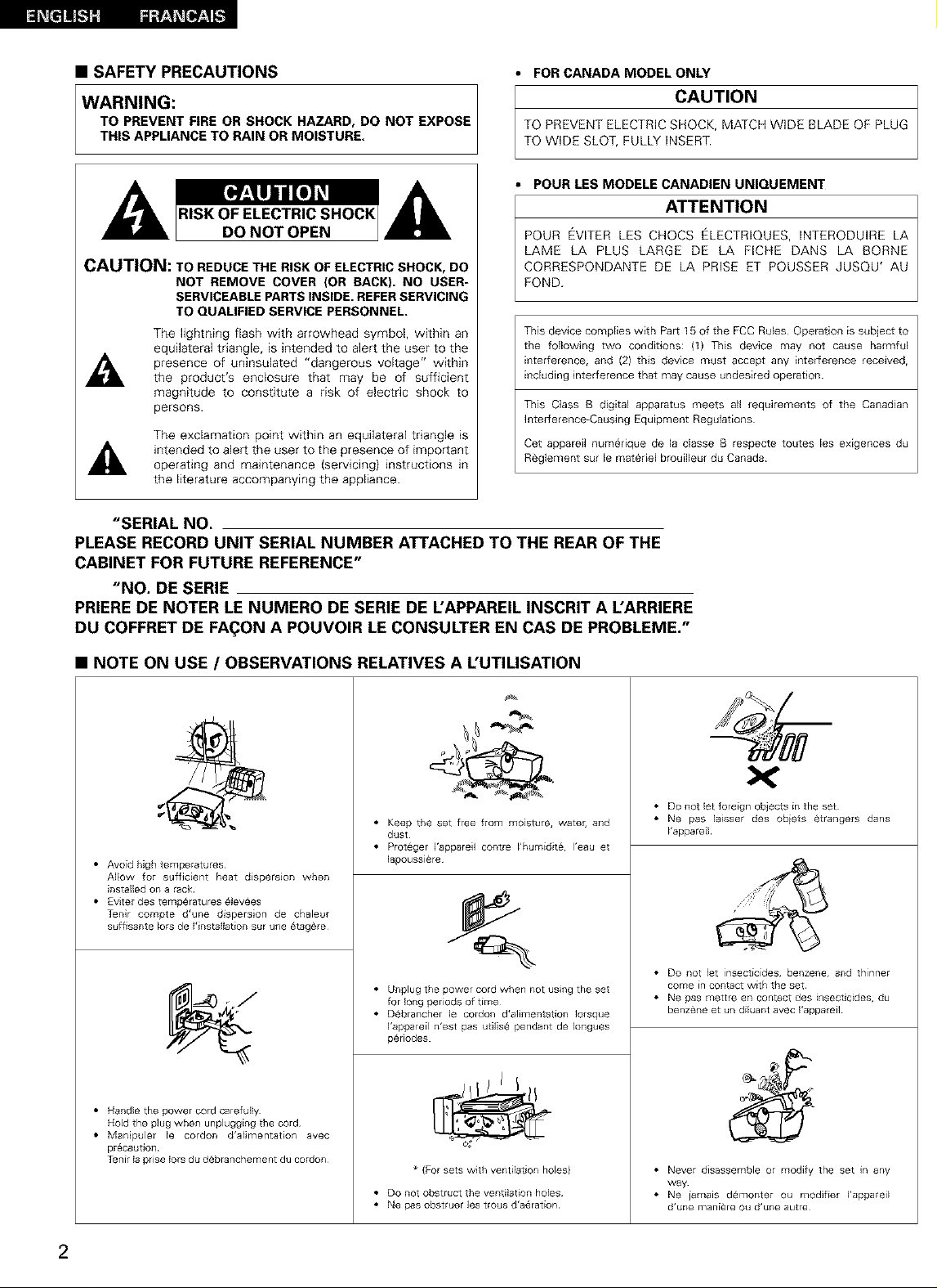
• SAFETY PRECAUTIONS
• FOR CANADA MODEL ONLY
WARNING:
TO PREVENT FIRE OR SHOCK HAZARD, DO NOT EXPOSE
THIS APPLIANCE TO RAIN OR MOISTURE.
TO PREVENT ELECTRIC SHOCK, MATCH WIDE BLADE OF PLUG
I CAUTION
TO WIDE SLOT, FULLY INSERT.
POUR LES MODELE CANADIEN UNIQUEMENT
ATTENTION
POUR EVITER LES CHOCS ELECTRIQUES, INTERODUIRE LA
LAME LA PLUS LARGE DE LA FICHE DANS LA BORNE
CAUTION: TO REDUCE THE RISK OF ELECTRIC SHOCK, DO
NOT REMOVE COVER (OR BACK). NO USER-
CORRESPONDANTE DE LA PRISE ET POUSSER JUSQU' AU
FOND.
SERVICEABLE PARTS INSIDE. REFER SERVICING
TO QUALIFIED SERVICE PERSONNEL.
The fightning flash with arrowhead symbol, within an
equilateral triangle, is intended to alert the user to the
presence of uninsulated "dangerous voltage" within
the product's enclosure that may be of sufficient
magnitude to constitute a risk of electric shock to
persons.
The exclamation point within an equilateral triangle is
intended to alert the user to the presence of important
operating and maintenance {servicing) instructions in
This device complies with Par_ 15 of the FCC Rules Operation is subject to
the following two conditions: (f) This device may not cause harmful
interference, and (2} this device must accept any interference recewed,
including interference that may cause undesired operation
This Class B digital apparatus meets all requirements of the Canadian
Interference-Causing Equipment Regulations
Get appareil numebque de la classe B respecte toutes les exigences du
Reglement sur le matebel brouilleur du Canada
the literature accompanying the appliance.
"SERIAL NO.
PLEASE RECORD UNIT SERIAL NUMBER ATTACHED TO THE REAR OF THE
CABINET FOR FUTURE REFERENCE"
"NO. DE SERIE
PRIERE DE NOTER LE NUMERO DE SERIE DE L'APPAREIL INSCRIT A L'ARRIERE
DU COFFRET DE FA(_ON A POUVOIR LE CONSULTER EN CAS DE PROBLEME."
• NOTE ON USE / OBSERVATIONS RELATIVES A L'UTILISATION
• Keep the set free from moisture, water, and
dust
• Proteger ]'appareil contre I'humidit6, I'eau et
• Avoid high temperatures
Allow for sufficient heat dispersion when
installed on a rack
• Evter des temperatures 6levees
Tenir compte d'une disperson de chaleur
suffisante lots de I'installation sur une _tag_re
• Handle the power cord carefully
Hold the plug when unplugging the cord
• Manipuler le cordon d'alimentation avec
pr6caution
Tenir la prise lots du deblanchement du cordon
lapoussicre
• Unplug the power cord when not using the set
for long periods of time
• Oebrancher le cordon d'alimentation Iorsque
I'appareil n'est pas utilise pendant de Iongues
periodes
* {For sets with ventilation holes)
• Do not obstruct the ventlat on holes
• Ne pas obstruer les trous d'aeration
• Do not let foreign objects in the set
• Ne pas laisser des obiets etrangers dans
I'appareil
• Do not let insecticides, benzene, and thinner
come in contact with the set
• Ne gas mettre en contact des insecticides, du
benzene et un diluant avec I'appareil
• Never disassemble or modify the set in any
way
• Ne jamais demonter ou modifier I'appareil
d'une maniare ou d'une autre
2
Page 3
SAFETY INSTRUCTIONS
1.
Read Instructions - All the safety and operating instructions
should be read before the appliance is operated.
2.
Retain Instructions - The safety and operating instructions
should be retained for future reference.
3.
Heed Warnings -AII warnings on the appliance and in the
operating instructions should be adhered to.
4.
Follow Instructions - All operating and use instructions
should be followed.
5.
Water and Moisture - The appliance should not be used
near water - for example, near a bathtub, washbowl,
kitchen sink, laundry tub, in a wet basement, or near a
swimming pool, and the like.
6.
Carts and Stands - The appliance should be used only with
a cart or stand that is recommended by the manufacturer
6A.
An appliance and cart
combination should be
moved with care.
Quick stops, excessive
force, and uneven
surfaces may cause
the appliance and cart
combination to overturn.
7.
Wail or Ceiling Mounting - The appliance should be
mounted to a wail or ceiling only as recommended by the
manufacturer
8.
Ventilation - The appliance should be situated so that its
location or position does not interfere with its proper
ventilation. For example, the appliance should not be
situated on a bed, sofa, rug, or similar surface that may
block the ventilation openings; of, placed in a built-in
installation, such as a bookcase or cabinet that may impede
the flow of air through the ventilation openings.
g.
Heat - The appliance should be situated away from heat
sources such as radiators, heat registers, stoves, or other
appliances (including amplifiers) that produce heat.
10.
Power Sources - The appliance should be connected to a
power supply only of the type described in the operating
instructions or as marked on the appliance.
11.
Grounding or Polarization - Precautions should be taken so
that the grounding or polarization means of an appliance is
not defeated.
12.
Power-Cord Protection - Power-supply cords should be
routed so that they are not likely to be walked on or pinched
by items placed upon or against them, paying particular
attention to cords at plugs, convenience receptacles, and
the point where they exit from the appliance.
14.
Cleaning - The appliance should be cleaned only as
recommended by the manufacturer
15.
Power Lines - An outdoor antenna should be located away
from power lines.
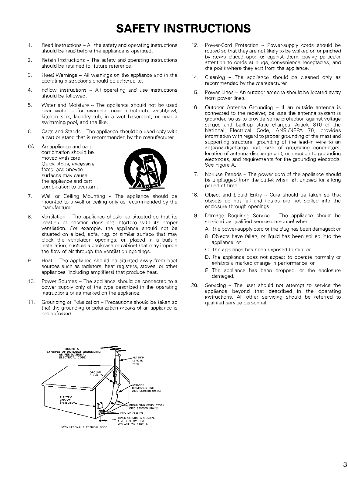
16.
Outdoor Antenna Grounding - If an outside antenna is
connected to the receiver, be sure the antenna system is
grounded so as to provide some protection against voltage
surges and built-up static charges. Article 810 of the
National Electrical Code, ANSl/NFPA 70, provides
information with regard to proper grounding of the mast and
supporting structure, grounding of the leadqn wire to an
antenna-discharge unit, size of grounding conductors,
location of antenna-discharge unit, connection to grounding
electrodes, and requirements for the grounding electrode.
See Figure A.
17.
Nonuse Periods - The power cord of the appliance should
be unplugged from the outlet when left unused for a long
period of time.
18.
Object and Liquid Entry - Care should be taken so that
objects do not fall and liquids are not spilled into the
enclosure through openings.
19.
Damage Requiring Service - The appliance should be
serviced by qualified service personnel when:
A. The power-supply cord or the ptug has been damaged; or
B. Objects have fallen, or liquid has been spilled into the
appliance; or
C. The appliance has been exposed to rain; or
D. The appliance does not appear to operate normally or
exhibits a marked change in performance; or
E. The appliance has been dropped, or the enclosure
damaged.
20.
Servicing - The user should not attempt to service the
appliance beyond that described in the operating
instructions. All other servicing should be referred to
qualified service personnel.
NEC.NATIONALELECTR_CALCODE
(NEC ART 25e. PART H_
Page 4
• INTRODUCTION
Thank you for choosing the DENON AVR-2802/982 Digital Surround A / V receiver. This remarkable component has been engineered to provide
superb surround sound listening with AV theater sources such as DVD, as well as providing outstanding high fidelity reproduction of your favorite
music sources.
As this product is provided with an immense array of features, we recommend that before you begin hookup and operation that you review the
contents of this manual before proceeding.
TABLE OF CONTENTS
Before Using .............................................................................. 4
Csutions on Installation ............................................................... 4
Cautions on Handling .................................................................. 5
Features .................................................................................... 5
Connections ........................................................................... 6~13
Part Names 8rid Functions ...................................................... 14, 15
Setting up the system ............................................................ 16~26
Remote Control Unit ............................................................... 27~35
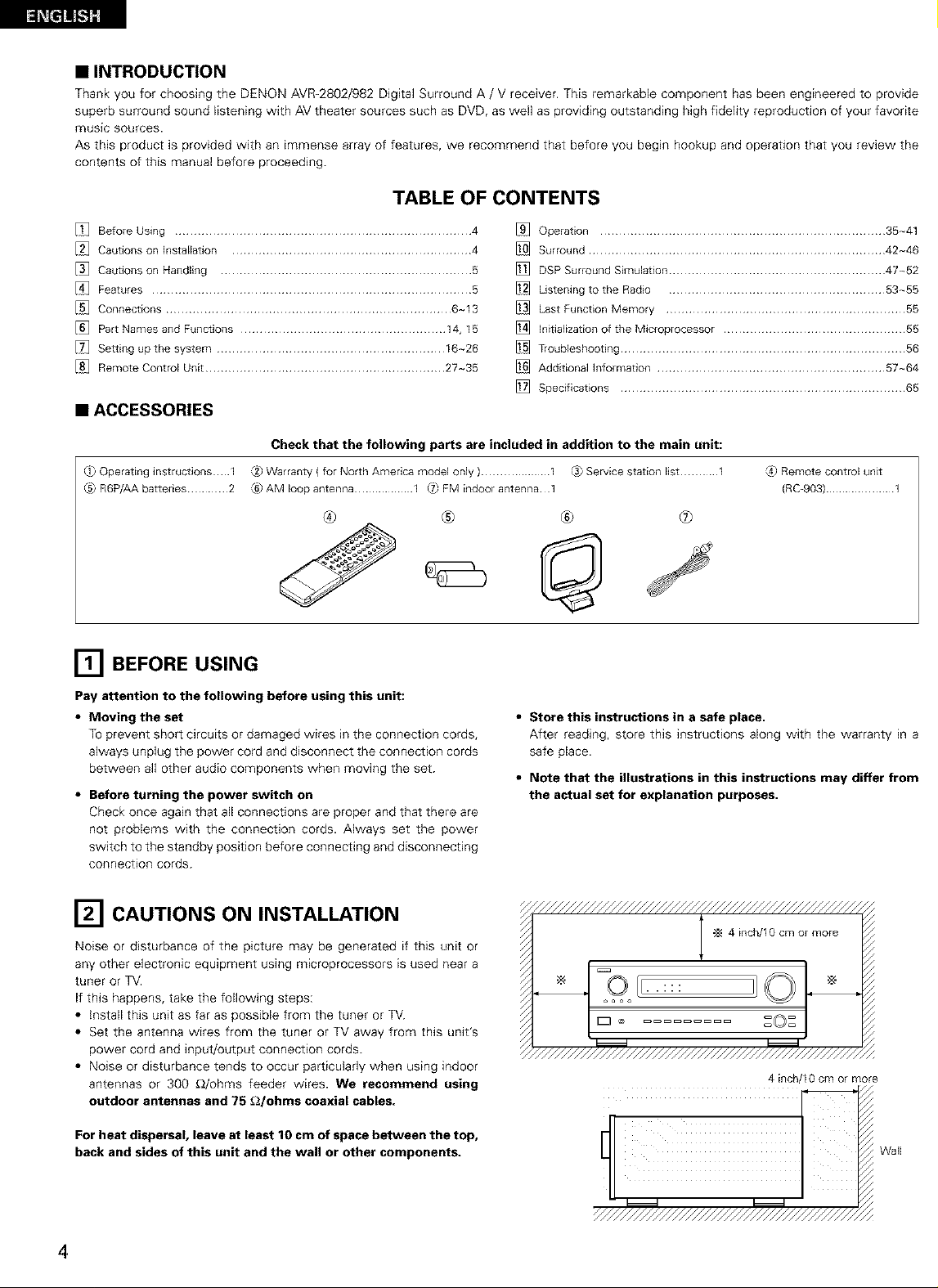
• ACCESSORIES
Check that the following parts are included in addition to the main unit:
_} Operating instructbns I
C5_R6P/AA batteries ............ 2
_2_Warranty ( for North America model only ).................... 1 C._Service station list ........... 1
_6)AM loop antenna .................. I _ FM indoor antenna 1
® ® ® ®
[] BEFORE USING
Pay attention to the following before using this unit:
• Moving the set
TOprevent short circuits or damaged wires in the connection cords,
always unplug the power cord and disconnect the connection cords
between all other audio components when moving the set.
• Before turning the power switch on
Check once again that all connections are proper and that there are
not problems with the connection cords. Always set the power
switch to the standby position before connecting and disconnecting
connection cords.
Operation ........................................................................... 35-41
Surround .............................................................................. 42-46
DSP Surround Simulation ......................................................... 47~52
Listening to the Radio ......................................................... 53~55
Last Function Memory ............................................................... 55
Initialization of the Microprocessor ................................................ 55
Troubleshooting ........................................................................... 56
Additional Information ............................................................ 57~64
Specifications ........................................................................... 65
[4) Remote Control unit
(RC-903) ..................... 1
• Store this instructions in a safe place.
After reading, store this instructions along with the warranty in a
safe place.
• Note that the illustrations in this instructions may differ from
the actual set for explanation purposes,
[] CAUTIONS ON INSTALLATION
Noise or disturbance of the picture may be generated if this unit or
any other electronic equipment using microprocessors is used near a
tuner or TV.
If this happens, take the following steps:
• install this unit as far as possible from the tuner or TV.
• Set the antenna wires from the tuner or TV away from this unit's
power cord and input/output connection cords.
• Noise or disturbance tends to occur particularly when using indoor
antennas or 300 _/ohms feeder wires. We recommend using
outdoor antennas and 75 £2/ohms coaxial cables.
For heat dispersal, leave at least 10 cm of space between the top,
back and sides of this unit and the wall or other components.
4
4 incP'10 cm or more
Wall
Page 5
[] CAUTIONS ON HANDLING
• Switching the input function when input jacks are not
connected
A clicking noise may be produced if the input function is switched
when nothing is connected to the input jacks, if this happens, either
turn down the MASTER VOLUME control or connect components
to the input jacks.
• Muting of PRE OUT jacks, HEADPHONE jack and SPEAKER
terminals
The PRE OUT jacks, HEADPHONE jacks and SPEAKER terminals
include a muting circuit. Because of this, the output signals are
greatly reduced for several seconds after the power switch is
turned on or input function, surround mode or any other-set-up is
changed, if the volume is turned up during this time, the output will
be very high after the muting circuit stops functioning. Always wait
until the muting circuit turns off before adjusting the volume.
[] FEATURES
1. Multi Room Music Entertainment System
Multi Source Function:
This unit's Multi Source function lets you select different audio or
video sources for viewing or listening Different sources can thus
be enjoyed in the main room and the subroom simultaneously.
2. Dolby Pro Logic II decoder
Dolby Pro Logic iI is a new format for playing multichannel audio
signals that offers improvements over conventional Dolby Pro
Logic. It can be used to decode not only sources recorded in Dolby
Surround but also regular stereo sources into five channels (front
left/right, center and surround left/right). In addition, various
parameters can be set according to the type of source and the
contents, so you can adjust the sound field with greater precision.
3. Dolby Digital
Using advanced digital processing algorithms, Dolby Digital
provides up to 5.1 channels of wide-range, high fidelity surround
sound. Dolby Digital is the default digital audio delivery system for
North American DVD and DTV.
• Whenever the power switch is in the STANDBY state, the
apparatus is still connected on AC line voltage.
Please be sure to unplug the cord when you leave home for,
say, a vacation.
4,
DTS (Digital Theater Systems)
DTS provides up to 5.1 channels of wide-range, high fidelity
surround sound, from sources such as laser disc, DVD and
specially encoded music discs.
5. DTS-ES Extended Surround and DTS Neo:6
The AVR-2802/982 is compatible with DTS-ES Extended Surround, a
new multi-channel format developed by Digital Theater Systems Inc.
The AVR-2802/982 is also compatible with DTS Neo:6, a surround
mode allowing 6.1-channel playback of regular stereo sources.
6. Component Video Switching
In addition to composite video and "S" video switching, the AVR-
2802/982 provides 2 sets of component video (Y, PB/Cs, PR/CR)
inputs for the DVD and TV/DBS inputs, and one set of component
video outputs to the television, for superior picture quality.
7, Video Select Function
Allow you to watch one source (visual) while listening to another
source (audio).
Page 6
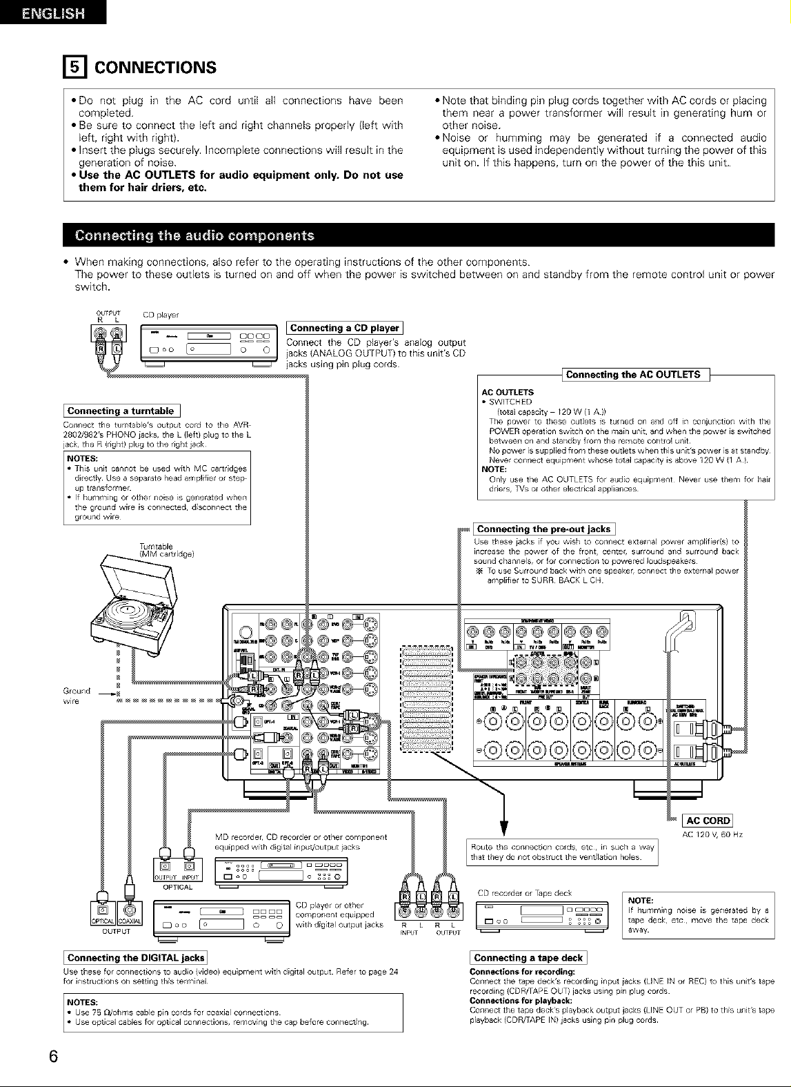
[] CONNECTIONS
• DO not plug in the AC cord until all connections have been
completed.
• Be sure to connect the left and right channels properly (left with
left, right with right).
• Insert the plugs securely. Incomplete connections will result in the
generation of noise.
• Note that binding pin plug cords together with AC cords or placing
them near a power transformer will result in generating hum or
other noise.
• Noise or humming may be generated if a connected audio
equipment is used independently without turning the power of this
unit on. If this happens, turn on the power of the this unit.
• Use the AC OUTLETS for audio equipment only. Do not use
them for hair driers, etc.
• When making connections, also refer to the operating instructions of the other components.
The power to these outlets is turned on and off when the power is switched between on and standby from the remote control unit or power
switch.
OU_I_OT CD player
{Connecting the AC OUTLETS ]
AC OUTLETS
I Connecting a turntable ]
Cor_[_ect the tumtable's output cord to the AVR
2802/982rs PHONO iacks, the L {Feft) PlU9 to the L
jack,, the R (right) plug to the ri9ht jack
• SWITCHED
(total capacity /20 W (1 A ))
The power to these Outlets is turned on and off in coniunct_on w_th the
POWER operation switch on the main unit, and when the power is switched
between on and standby from the remote control unit
driers, TVs ot other electrical appliances
Tumtable
(MM cartridge)
Ground _
wl_e
MD recotder, CD recorde[ or other component
equipped with digital input/output iacks
_ _ DDDD component equlpped
o o _ o _ _ with digital output jacks R L R L
OUTPUT _NPt;T OUTI_U
i O _ CD player or other
I Connecting the pro*out jacks I
Use these iacks if you wish to conllect externaJ power amplifier(s) to
increase the power of the front, ceiitet, surlound alld suiround back
soured chanr_els, or for co_nectiorl to powered Ioudspeakels
To use Surround bac_, with one speaker, connect the exterila_ power
ampiifler to SURR BACK L CH
_n_r,_
S
AC /20 V, 60 Hz
CD recorder or Tape deck,
= _ a _acn NOTE:
, _ _ • away
i Connecting the DIGITAL jacks ]
Use these for collnect_ons to audio (v_deol equipment with digital output Refer to page 24
for instructions on settling this terminal
6
Connecting a tape deck]
Connections for recording:
Connect tile tape deck's recording _rlpu_ iac_,s (LINE _N or REC) to this urllt's tape
recording {CDR/TAPE OUT) jacks using pin plug cords
Connections for playback:
Corl[lect the tape deck's playback output jacks {LINE OUT or PB) to this urllt's tape
playback, (CDR/TAPE IN) jacks using pirl plug cords
Page 7
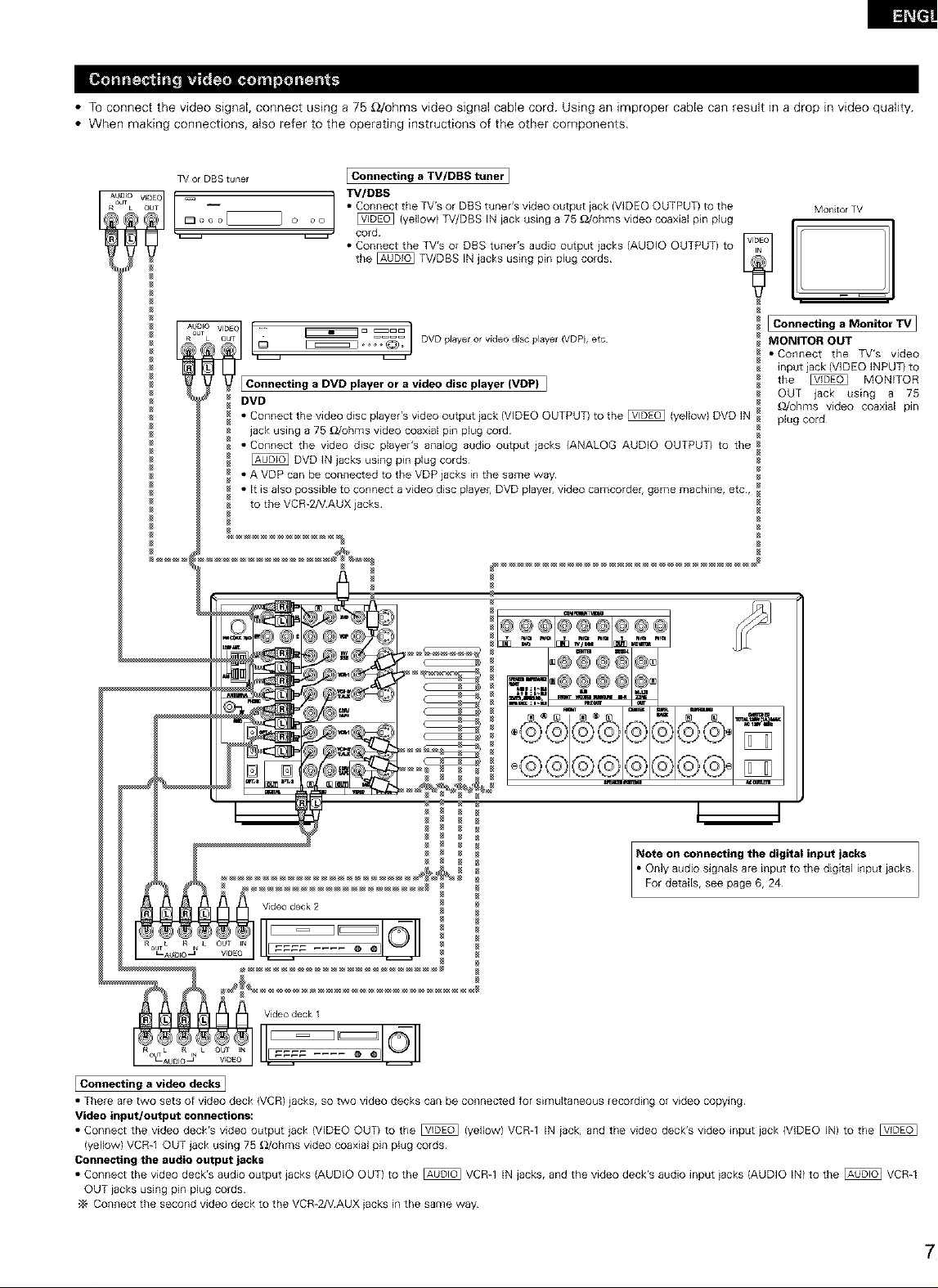
• TO connect the video signal, connect using a 75 _2/ohms video signal cable cord. Using an improper cable can result in a drop in video quality.
• When making connections, also refer to the operating instructions of the other components.
TV or DBS tunel I Connecting a TV/DBS tuner I
VlOEO _ TV/DBS
ou _ • Connect the TV's or DBS tuner's video output iack {VIDEO OUTPUT) to the
I:_ o oo _ _ (yellow) TV/DBS IN iack using a 75 _Johms video coaxial pin plug
L O oo
Connecting a DVD player ora video disc player (VDP)I
DVD
• Connect the video disc player's video output jack (VIDEO OUTPUT) to the _ (yellow) DVD IN
jack using a 75 _Johms video coaxial pin plug cord
• Connect the video disc player's analog audio output jacks {ANALOG AUDIO OUTPUT) to the
[_ DVD IN jacks using pin plug cords
• A VDP can be connected to the VDP jacks in the same way
• It is also possible to connect a video disc playel, DVD playel, video camcorder, game machine, etc,
to the VCR-2/VAUX jacks
_ cord
• Connect the TV's or DBS tuner's audio output iacks (AUDIO OUTPUT) to
the _ TV/DBS IN jacks using pin plug cords
Monitor TV
I Connecting a Monitor TV I
MONITOR OUT
• Connect the TV's video
input iack (VIDEO INPUT} to
the _ MONITOR
OUT jack using a 75
_/ohms video coaxial pin
plug cord¸
D_
o@C@©
Note on connecting the digital input jacks
• OnlYFordetails,aUdi°signalSseepageare6,input24to the digital input iacks
I Connecting a video decks]
• There are two sets of video deck (VCR) jacks, so two video decks can be connected for simultaneous recording or video copying
Video input/output connections:
• Connect the video deck's video output jack (VIDEO OUT) to the _ {yellow) VCR-1 IN iack, and the video deck's video input iack (VIDEO IN) to the
(yellow) VCR-1 OUT jack using 75 OJohms video coaxial pin plug cords
Connecting the audio output jacks
• Connect the video deck's audio output jacks (AUDIO OUT) to the _ VCR-1 IN jacks, and the video deck's audio input iacks (AUDIO IN) to the _ VCR-1
OUT iacks using pin plug cords
•_ Connect the second video deck to the VCR-2NAUX iacks in the same way
Page 8
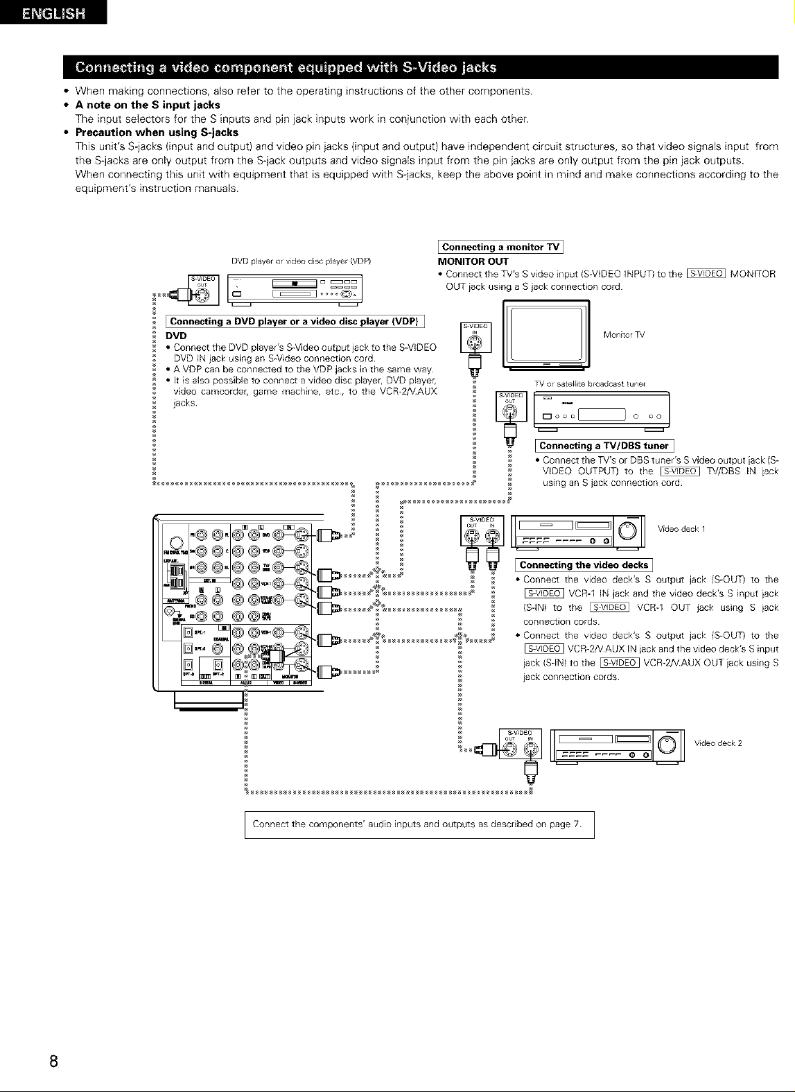
• When making connections, also refer to the operating instructions of the other components.
• A note on the S input jacks
The input selectors for the S inputs and pin jack inputs work in conjunction with each other.
• Precaution when using S-jacks
This unit's S-jacks (input and output) and video pin jacks (input and output) have inde _endent circuit structures, so that video signals input from
the S-jacks are only output from the S-jack outputs and video signals input from the pin iacks are only output from the pin jack outputs.
When connecting this unit with equipment that is equipped with S jacks, keep the above )oint in mind and make connections according to the
equipment's instruction manuals.
Connecting a monitor TV I
DVD player or video disc player (VDP)
[ Connecting a DVD player or a video disc player (VDP) ]
DVD
• Connect the DVD player's S-Video output jack to the SWIDEO
DVD IN iack using an S-Video connection cord
• A VDP can be connected to the VDP jacks in the same way
• It is also possible to connect a video disc player, DVD player,
video camcorde game machine, etc, to the VCR-2/VAUX
jacks
_H_H_H_ using an S jack connection cord
MONITOR OUT
• Connect the TV's S video input (S-VIDEO INPUT) to the _ MONITOR
OUT iack using a S jack connection cord¸
E [wMontorTv
TV or satellite b¢oadcast tuner
I Connecting a TV/DBS tuner I
• Connect the TV's or DBS tuner's S video output iack {S-
VIDEO OUTPUT) to the _ TV/DBS IN iack
s v,oEo _
_ _ Vrdeodeck 1
iconn°ct,not.ev,deoO°o..I
_ * Connect the video deck's S output jack (S-OUT) to the
_ VCR_I IN jack and the video deck's S input iack
(SqN) to the _ VCR_I OUT jack using Siack
connection cords
• Connect the video deck's S output jack (S-OUT) to the
VCR-2N AUX IN iack and the video deck's S input
jack (SdN) to the _ VCR-2NAUX OUT iack using S
jack connection cords
Connect the components' audio inputs and outputs as described on page 7 I
Video deck 2
8
Page 9
• When making connections, also refer to the operating instructions of the other components.
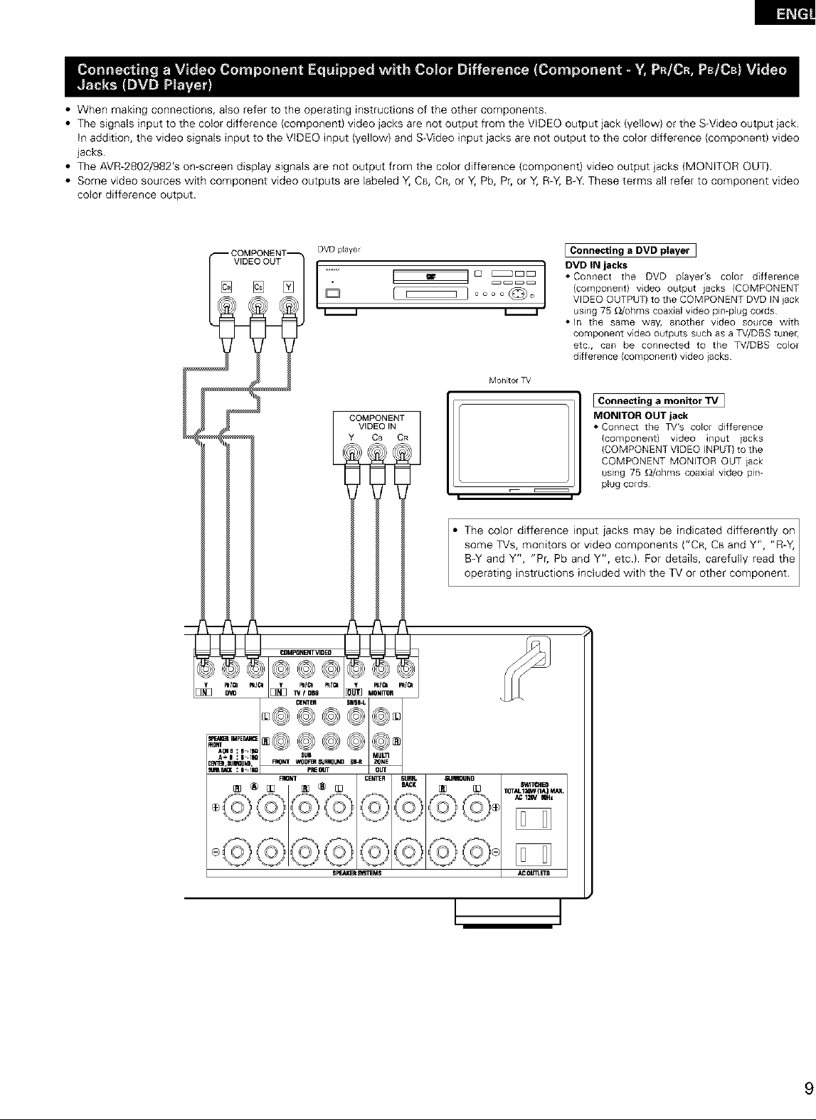
• The signals input to the color difference (component) video jacks are not output from the VIDEO output jack (yellow) or the S-Video output jack.
in addition, the video signals input to the VIDEO input (yellow) and SWideo input jacks are not output to the color difference (component) video
jacks.
• The AVR-2802/982'S on-screen display signals are not output from the color difference (component) video output jacks (MONITOR OUT).
• Some video sources with component video outputs are labeled Y, C8, CR, or Y, Pb, Pr, or Y, R-Y, B-Y. These terms all refer to component video
color difference output.
DVD player
v'°e°°°TI........ ]
Mon_tol TV
COMPONENT
VIDEO IN
Y CB OR
The color difference input iacks may be indicated differently on I
some TVs, monitors or video components ("CR, CBand Y", "R-Y, I
B-Y and Y", "Pr, Pb and Y", etc.). For details, carefully read the
operat ng nstruct ons nc uded w th the TV or other component.
I Connecting a DVD player
DVD IN jacks
• Connect the DVD pEayer's coEor difference
(component} video output jacks (COMPONENT
VIDEO OUTPUT) to the COMPONENT DVD IN iack
using 75 _/ohms coaxial video pin-plug cords
• In the same way, another video source with
component video outputs such as a TV/DBS tuner,
etc, can be connected to the TV/DBS color
difference (component) video iacks
Connecting a monitor TV 1
MONITOR OUT jack
• Connect the TV's color difference
Icomponentl video input iacks
ICOMPONENT VIDEO ENPUTI to the
COMPONENT MONITOR OUT iack
using 75 _/ohms coaxial video p_n-
plug cords¸
Page 10
D_RECTiON OF
BROADCAST_NG
STATION
I
FM ANTENNA
75_ohms
COAXIAL
CABLE
FM_NDOOR
ANTENNA
(Supplied)
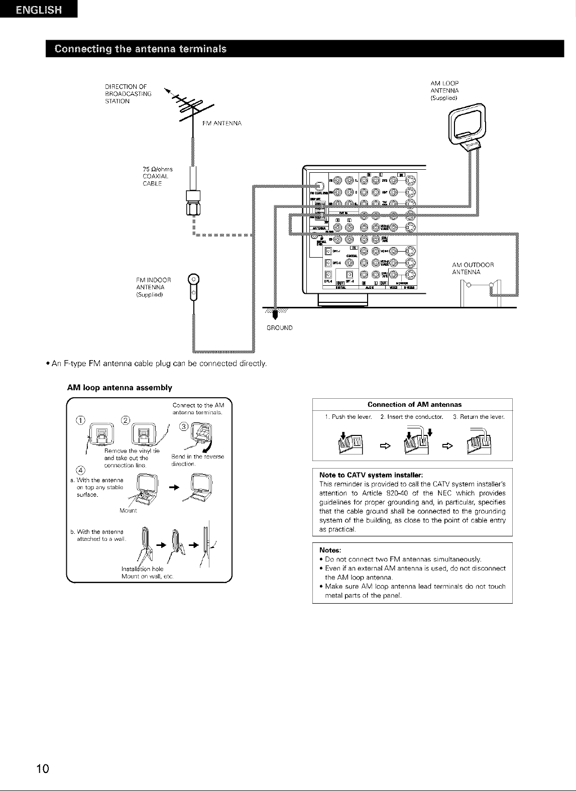
• An F4ype FM antenna cable plug can be connected directly.
GROUND
AM LOOP
ANTENNA
(Suppl_ed}
AM OUTDOOR
ANTENNA
AM loop antenna assembly
(_) _R e_move the v_nyl de
and take Out the
a With the ar_tenr/a
b With the antenna
conne¢l_o[ _ _ir}e
on top any stable
su_faee
attached to a wa_l
Mount
a_tenna tot mina,s
Bend in the teverse
direction
Connection of AM antennas
1 Push the level 2 ]nsett the collductol 3 Returll the _ever
Note to CATV system installer:
This reminder is provided to call the CATV system installer's
attention to Article 820-40 of the NEC which provides
guidelines for proper grounding and, in particular, specifies
that the cable ground shall be connected to the grounding
system of the building, as close to the point of cable entry
as practical
Notes:
• DO not connect two FM antennas simultaneously
• Even if an external AM antenna is used, do not disconnect
the AM loop antenna
• Make sure AM loop antenna lead terminals do not touch
metal paris of the panel
10
Page 11
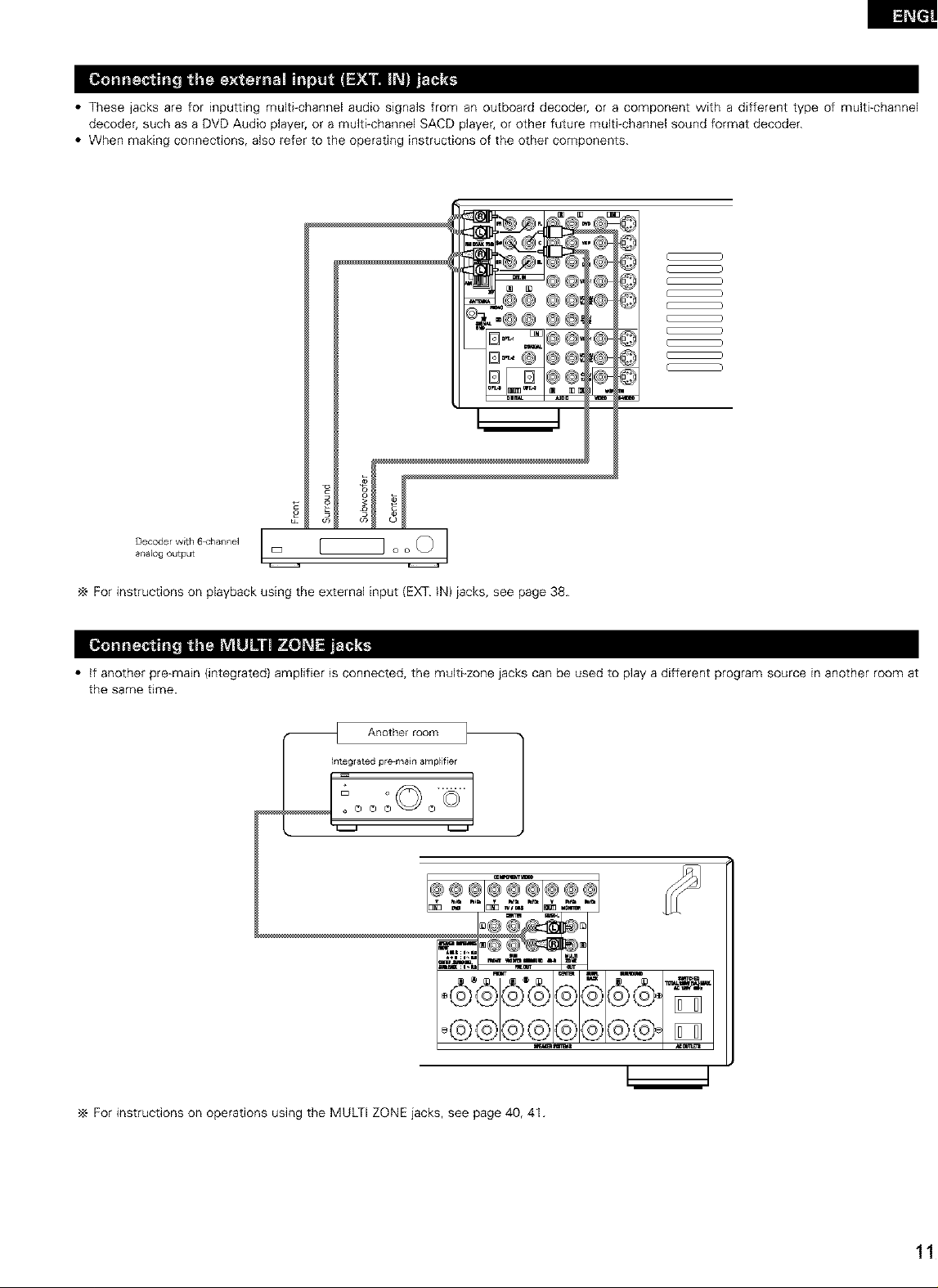
• These jacks are for inputting multi-channel audio signals from an outboard decoder, or a component with a different type of multi-channel
decoder, such as a DVD Audio player, or a multi-channel SACD player, or other future multi-channel sound format decoder.
• When making connections, also refer to the operating instructions of the other components.
C )
C )
C )
( )
@@_I@
Dr D@@_
c
Decoder with 6 <'hannel
analog output
I
For instructions on playback using the external input (EXT. IN) jacks, see page 38.
• if another pre-main (integrated) amplifier is connected, the multi-zone jacks can be used to play a different program source in another room at
the same time.
hteglated pre main amplifier
_ Another room _ 1
E_ O Q ©"
© ©
_ : i .,u r_OUT Ou,
C
@@g©
For instructions on operations using the MULTI ZONE jacks, see page 40, 41.
Page 12
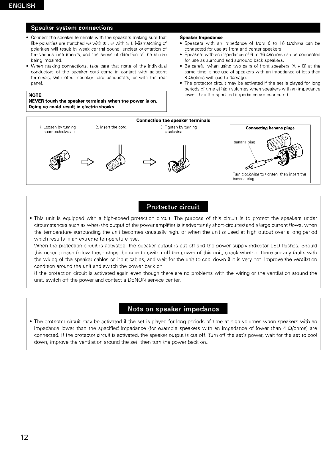
• Connectthespeakerterminalswiththespeakersmakingsurethat
likepolaritiesarematched{®withO,QwithQ).Mismatchingof
polaritieswillresultinweakcentralsound,unclearorientationof
thevariousinstruments,andthesenseofdirectionofthestereo
beingimpaired.
• Whenmakingconnections,takecarethatnoneoftheindividual
conductorsofthespeakercordcomeincontactwithadjacent
terminals,withotherspeakercordconductors,orwiththerear
panel.
NOTE:
NEVER touch the speaker terminals when the power is on.
Doing so could result in electric shocks.
Connection the speaker terminals
1 Loosen by turning
counterclockwise
2 Insert the cord 3 _ghten by turning
clockwise
Speaker Impedance
• Speakers with an impedance of from 6 to 16 _2/ohms can be
connected for use as front and center speakers.
• Speakers with an impedance of 6 to 16 _/ohms can be connected
for use as surround and surround back speakers.
• Be careful when using two pairs of front speakers (A + B) at the
same time, since use of speakers with an impedance of less than
8 _/ohms will lead to damage.
• The protector circuit may be activated if the set is played for long
periods of time at high volumes when speakers with an impedance
lower than the specified impedance are connected.
Connecting banana plugs
Turn clockwise to tighten, then insert the
banana plug
,, This unit is equipped with a high-speed protection circuit. The purpose of this circuit is to protect the speakers under
circumstances such as when the output of the power amplifier is inadvertently short-circuited and a large current flows, when
the temperature surrounding the unit becomes unusually high, or when the unit is used at high output over a long period
which results in an extreme temperature rise.
When the protection circuit is activated, the speaker output is cut off and the power supply indicator LED flashes. Should
this occur, please follow these steps: be sure to switch off the power of this unit, check whether there are any faults with
the wiring of the speaker cables or input cables, and wait for the unit to cool down if it is very hot. Improve the ventilation
condition around the unit and switch the power back on.
If the protection circuit is activated again even though there are no problems with the wiring or the ventilation around the
unit, switch off the power and contact a DENON service center.
,, The protector circuit may be activated if the set is played for long periods of time at high volumes when speakers with an
impedance lower than the specified impedance (for example speakers with an impedance of lower than 4 _/ohms) are
connected. If the protector circuit is activated, the speaker output is cut off. Turn off the set's power, wait for the set to cool
down, improve the ventilation around the set, then turn the power back on.
12
Page 13
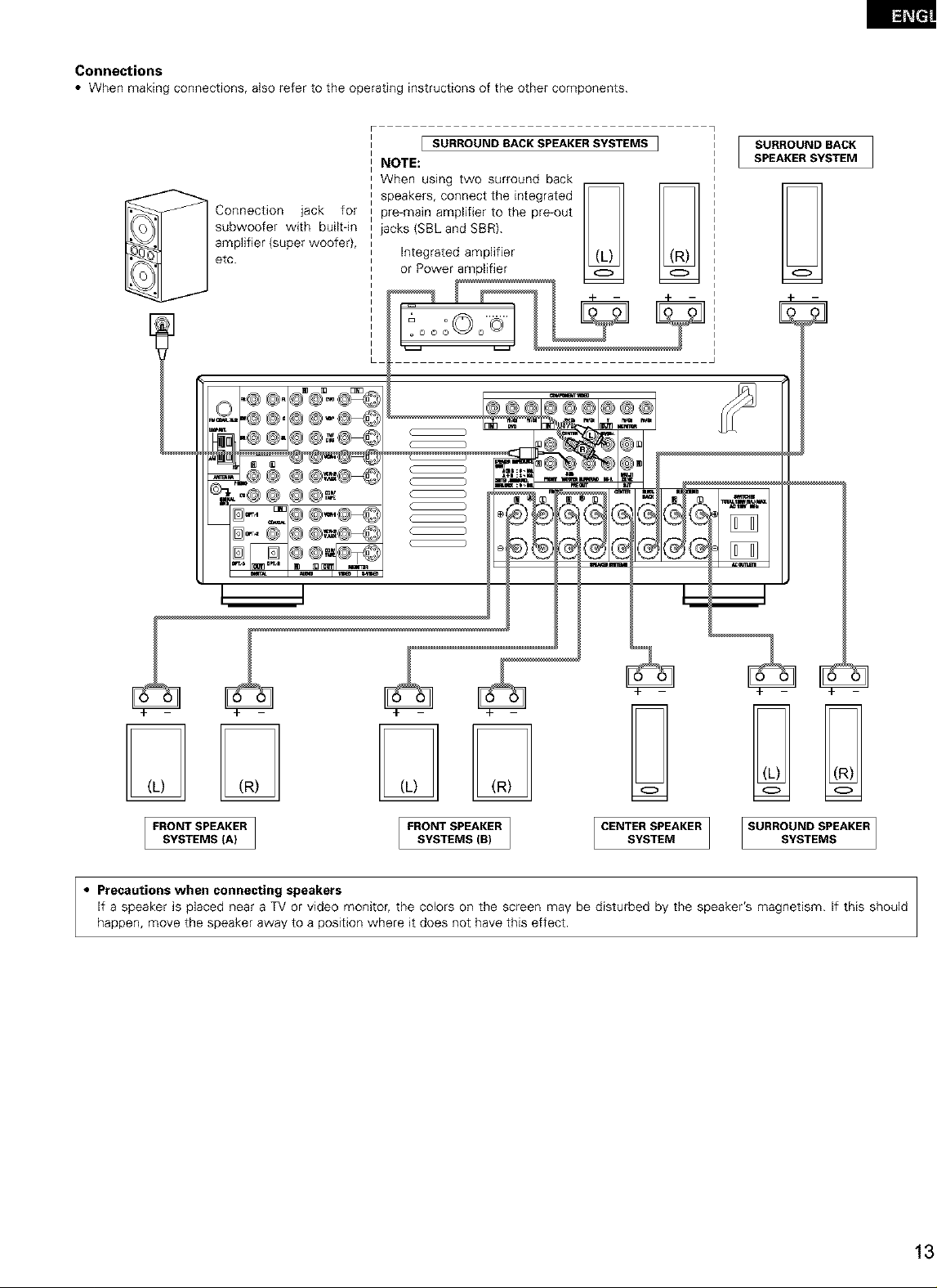
Connections
• When making connections, also refer to the operating instructions of the other components.
_ Connection jack for
subwoofer with buik-in
amplifier (super woofer),
etc.
[ SURROUND SACK SPEAKERSYSTEMS ]
NOTE:
When using two surround back
o
- - %._
m
SURROUND BACK
SPEAKER SYSTEM
7
G
FRONT SPEAKER FRONTSPEAKER [ CENTER SPEAKER ] SURROUND SPEAKER
SYSTEMS (A) SYSTEMS (B) SYSTEM SYSTEMS
• Precautions when connecting speakers
If a speaker is placed near a TV or video monitor, the colors on the screen may be disturbed by the speaker's magnetism. If this should
happen, move the speaker away to a position where it does not have this effect.
Page 14
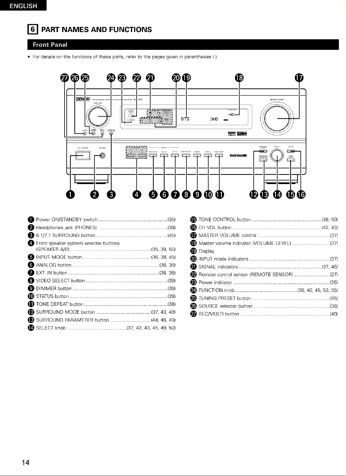
[] PART NAMES AND FUNCTIONS
• For details on the functions of these parts, refer to the pages given in parentheses ().
Power ON/STANDBY switch .................................................... (35)
Headphones jack (PHONES) .................................................... (39)
6.1/7.1 SURROUND button ...................................................... (45)
_ Front speaker system selecter buttons
(SPEAKER A/B) ............................................................. (35, 39, 55)
INPUT MODE button ................................................... (36, 38, 45)
ANALOG button ................................................................. (36, 38)
EX_. IN button .................................................................... (36, 38)
VIDEO SELECT button ............................................................. (39)
DIMMER button ....................................................................... (39)
_) STATUS button ......................................................................... (39)
TONE DEFEAT button .............................................................. (38)
SURROUND MODE button ......................................... (37, 43, 49}
_) SURROUND PARAMETER button ............................... (44, 46, 49}
SELECT knob ............................................. (37, 42, 43, 45, 49, 50}
TONE CONTROL button .................................................... (38.50)
_} CH VOL button ................................................................... (42, 43)
MASTER VOLUME control ...................................................... (37)
_) Master volume indicator (VOLUME LEVEL) ............................ {37)
Display
INPUT mode indicators ............................................................ {37}
i_ SIGNAL indicators .............................................................. (37, 45}
i_ Remote control sensor (REMOTE SENSOR) ........................... (27}
Power indicator ........................................................................ {35)
i_ FUNCTION knob .............................................. (36, 40, 45, 53, 55}
i_ TUNING PRESET button .......................................................... {55)
SOURCE selector button ......................................................... {36)
i_ REC/MULTI button ................................................................... {40)
14
Page 15
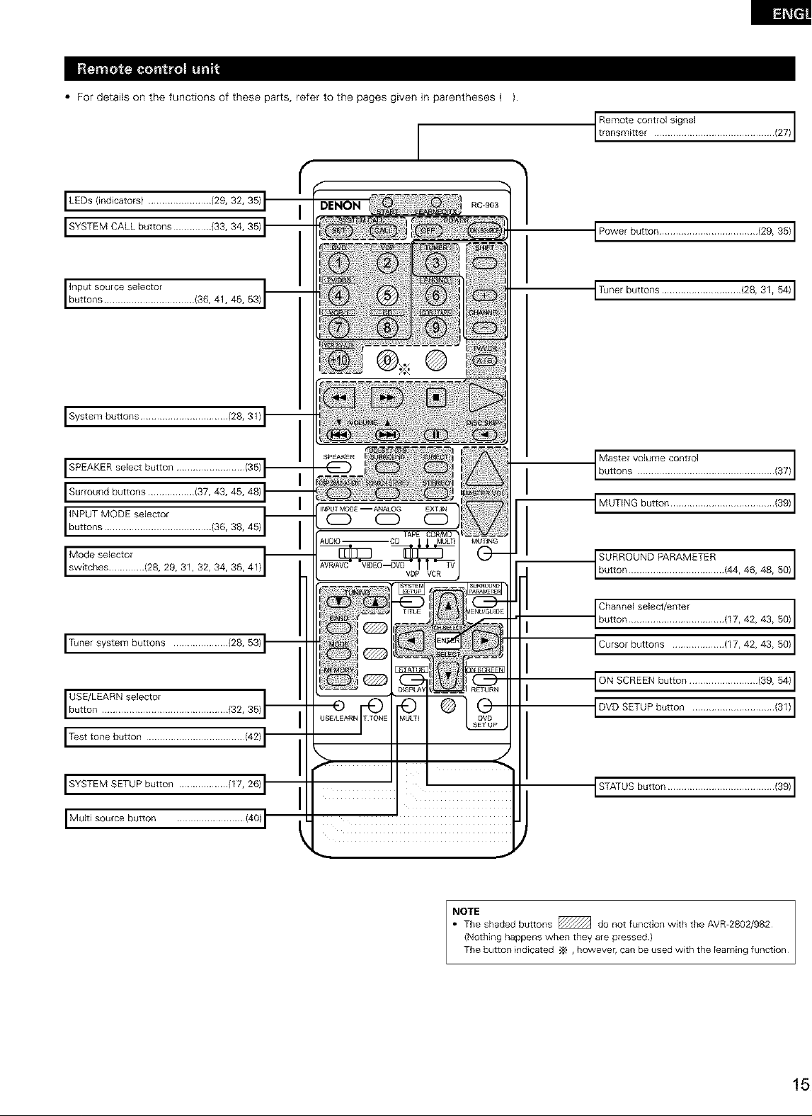
• For details on the functions of these parts, refer to the pages given in parentheses ( }.
I
t tRaenms_t?tcont K_J sig?a, ............................. (27) I
I LEDs (indicators) ....................... {29, 32, 35)
I SYSTEM CALL buttons .............. (33, 34, 35}
I IbnuPt_tnSs°Ulcese!e?°i ............ (36, 41, 45, 53)
I System buttons ................................ (28, 31)
I SPEAKER select button ......................... (35)
I Surround buttons ................. (37, 43, 45, 48)
'"'_"rb':t_,',s'V_?Ett'?iltr...............(86,38,45)
I
I siWw°tdc_]Seltctci[ (28, 29, 31, 32, 34, 35, 41)
1
I Power button .................................... (29, 35) 1
I Tuner buttons ............................. (28, 31, 54) I
Ib:it?sV?::::?:'............................'3_'1
IMUTING button ...................................... (39_I
I_o_,_ot 484959/I
ITunersystem buttons .................... (28,53)
I USE/L ARN se ect°rI button E I ........................ {32, 35]
I Test tone button .................................... (42)
I SYSTEM SETUP button .................. (17, 26)
I Multi source button ......................... (40)
_Chonnose,eot,on_botton'ttr............,17,42,48,59,_
ICursor buttons ................... (17, 42, 43, 50) I
ION SCREEN button ......................... (39, 54) 1
IDVD SETUP button .............................. (31) I
STATUS button ....................................... (39) 1
_TEe shaded buttons _ do not function with the AVD2802/982
(Nothing happens when they are pressed)
The button indicated ,_ , however, can be used with the learning function
Page 16
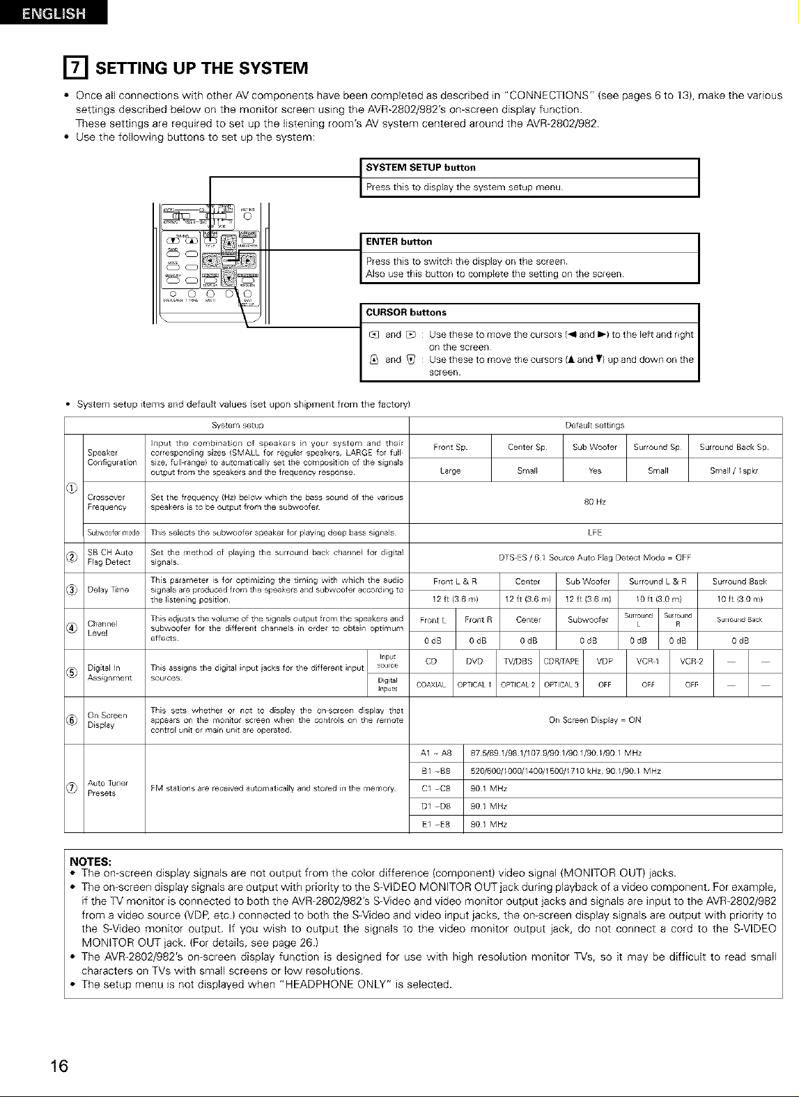
[] SETTING UP THE SYSTEM
• Once all connections with other AV components have been completed as described in "CONNECTIONS" (see pages 6 to 13), make the various
settings described below on the monitor screen using the AVR-2802/982'S on-screen display function.
These settings are required to set up the listening room's AV system centered around the AVR-2802/982.
• Use the following buttons to set up the system:
_rYe:::hiMs t__iUs:lal:lyUtt_:nsystem setup menu I
_J and [zb : Use these to move the cursors 1_1 and I_) to the Eeft and right
_iq and _Z/ : Use these to move the cursors (l and T) up and down on the
/ screen /
• System setup items and default values (set upon shipment from the factory)
System setup
Speaker
Collfiguration
C¢ossove_
F_equency
Su_w0ofelmode
SB CH Auto
_ Flag Detect
_ Delay _me
_ Channel
Level
Digital _n
@_ Assignment
_ On Screen
Display
_7_ Auto Tuner
Presets
]llput the combination of speakers in your system and thelr
correspondMg sizes {SMALL tot regular speakers, LARGE for full
size, full range} to automatically set tile composition of the slglla_s
output from the speakers and the frequency respollse
Set the frequency (Hz) below which the bass sound of the various
speakers is to be output from the subwooter
This selects the subwoofer speaker for playing deep bass signals
Set the method of p_aying the surround back channel for d_gltal
slgna_s
This parameter is for optimizing the timlng with which the audio
slgna_s are produced from the speakers and subwoofer accotding to
the listening posidoll
This adiust s the volume of the signals output from the speakers and
subwoofer for the dJffeterlt charlrle_s _rl order to obtain optlmum
effects
This asslglls the digital input iacks for the different input source
sources Digital
This sets whether or not to display the on screer_ display that
appea_s on the monito¢ screen when the controls on the remote
control unit or ma_n unit are operated¸
FM stations are received automatically and stored in the memory
_npt
Ir_puts
on the screen
Default settings
Front Sp
Large
Front L & R Center Sub Woofer
12 ft (36 m) 12 ft (36 m) 12 ft (36m)
Fro_t L Frorlt R Center Subwoofer
OdB OdB OdB OdB
CD DVD ]_7/DBS CDRFAPE VDP
COAXIAL OPTICALI OPTICAL 2 OPTICAL3 OFF
A1 -- A8 87 5/89 1/98 1/107 9/901/901/90//90/ MHz
B/ -g8 520/600//000/1400/1500//710 kHz, 90//90/ MHz
C/ -C8 90 1 MHz
D/ -D8 90 1 MHz
E/ -E8 90 1 MHz
Center Sp Sub Woofer Surround Sp
Smal_ Yes Small
80 Nz
LFE
DTS ES / 6 1 Source Auto Flag Detect Mode = OFF
Surround L & R
su Found Surround
0dB OdB
On Screen Display = ON
/0 ft (3Ore)
L R
VCR 1 VCR 2
OFF OFF
Surround Back Sp
Small //spkr
Surround Back
lOft{SOre)
Surround Back
OdB
NOTES:
• The on screen display signals are not output from the color difference (component) video signal (MONITOR OUT) jacks.
• The on-screen display signals are output with priority to the S-VIDEO MONITOR OUT jack during playback of a video component. For example,
if the TV monitor is connected to both the AVR-2802/982's S Video and video monitor output jacks and signals are input to the AVR-2802/982
from a video source (VDP, etc.) connected to both the SWideo and video input jacks, the on screen display signals are output with priority to
the S-Video monitor output. If you wish to output the signals to the video monitor output jack, do not connect a cord to the SWIDEO
MONITOR OUT jack. (For details, see page 26.)
• The AVR-2802/982'S on screen display function is designed for use with high resolution monitor TVs, so it may be difficult to read small
characters on TVs with small screens or low resolutions.
• The setup menu is not displayed when "HEADPHONE ONLY" is selected.
16
Page 17
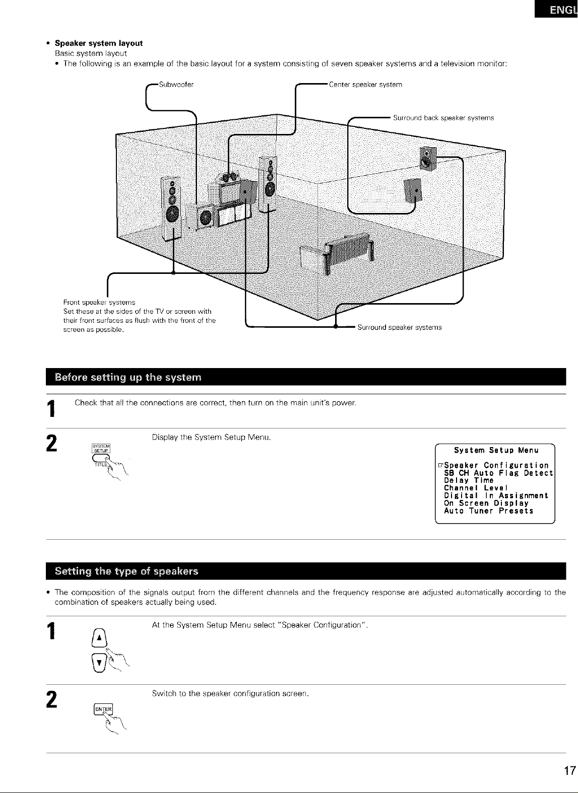
• Speaker system layout
Basic system layout
• The following is an example of the basic layout for a system consisting of seven speaker systems and a television monitor:
_Centerspeakersystem
Surround back speaker systems
r
Front speaker systems
Set these atthe sides of the TVor screen with
their front sur[aces as flush with the front of the
screen as possible
Surround speaker systems
Check that all the connections are correct, then turn on the main unit's power.
Display the System Setup Menu.
• The composition of the signals output from the different channels and the frequency response are adjusted automatically according to the
combination of speakers actually being used.
At the System Setup Menu select "Speaker Configuration'.
System Setup Menu
_Speaker Configuration
SB CH Auto Flag Detect
Delay Time
Channel Level
Digital In Assignment
On Screen Display
Auto Tuner Presets
k
1
Switch to the speaker configuration screen.
Page 18
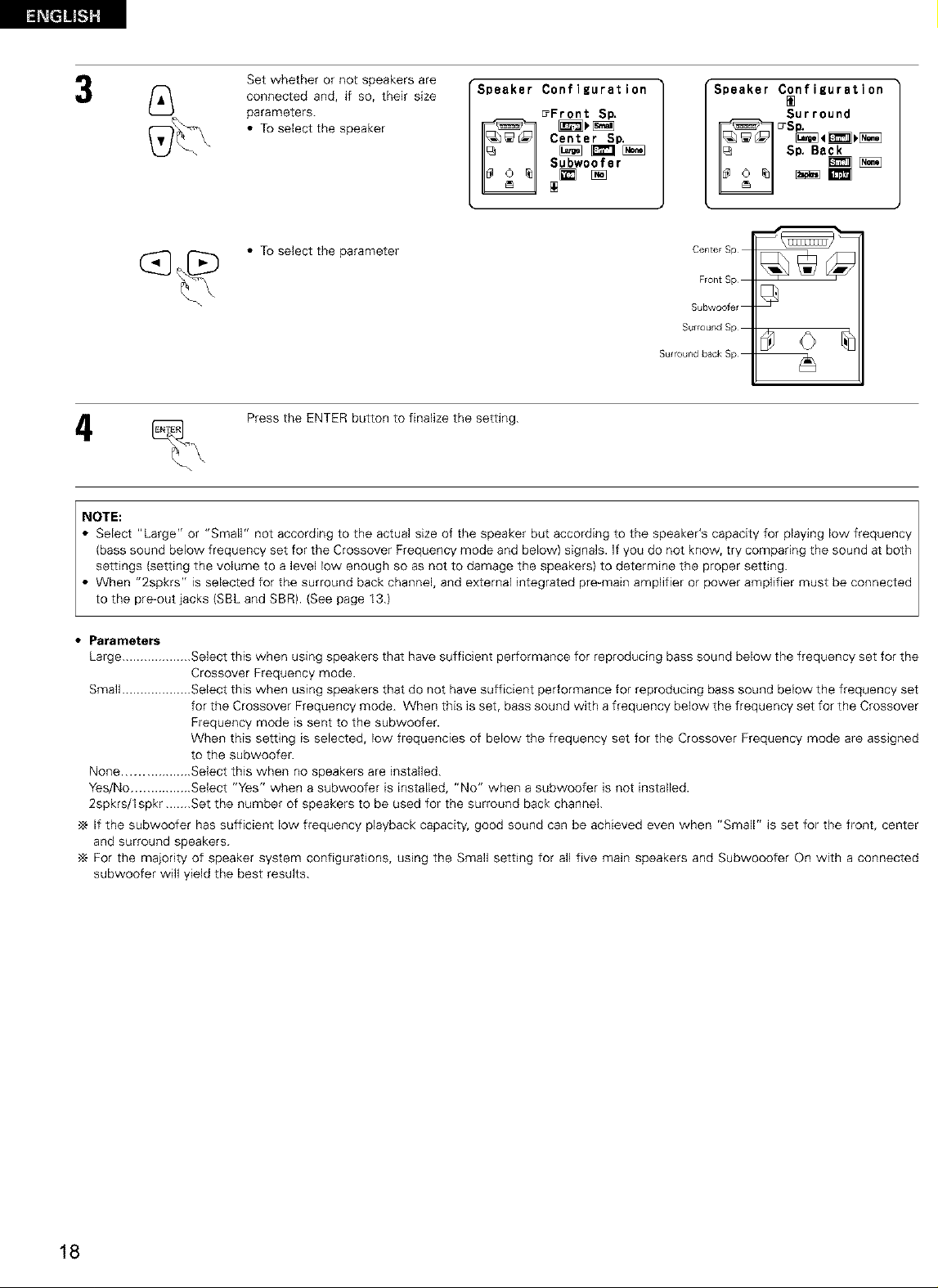
Setwhetherornotspeakersare
connectedand,if so,theirsize
parameters.
• Toselectthespeaker
SpeakerConfiguration
E_FrontSto.
Center SD.
Subwoofer
Speaker Configuration
Surround
SP. Ba_
_m
(_ _[_ • To select the parameter Center Sp
Press the ENTER button to finalize the setting.
Front Sp
Subwoofer
Surround Sp
Surround back Sp
..o,E= I
Select "Large" or "Small" not according to the actual size of the speaker but according to the speaker's capacity for playing low frequency
(bass sound below frequency set for the Crossover Frequency mode and below) signals. Ifyou do not know, try comparing the sound at both
settings (setting the volume to a level low enough so as not to damage the speakers) to determine the proper setting. I
• When "2spkrs" is selected for the surround back channel, and external integrated pre-main amplifier or power amplifier must be connected
to the pre-out acks SBL and SBR. See page 13.
• Parameters
Large ................... Select this when using speakers that have sufficient performance for reproducing bass sound below the frequency set for the
Crossover Frequency mode.
Small ................... Select this when using speakers that do not have sufficient performance for reproducing bass sound below the frequency set
for the Crossover Frequency mode. When this is set, bass sound with a frequency below the frequency set for the Crossover
Frequency mode is sent to the subwoofer.
When this setting is selected, low frequencies of below the frequency set for the Crossover Frequency mode are assigned
to the subwoofer.
None .................. Select this when no speakers are installed.
Yes/No ................ Select "Yes" when a subwoofer is installed, "No" when a subwoofer is not installed.
2spkrs/lspkr.......Set the number of speakers to be used for the surround back channel.
•_ If the subwoofer has sufficient low frequency playback capacity, good sound can be achieved even when "Small" is set for the front, center
and surround speakers.
For the majority of speaker system configurations, using the Small setting for all five main speakers and Subwooofer On with a connected
subwoofer will yield the best results.
18
Page 19
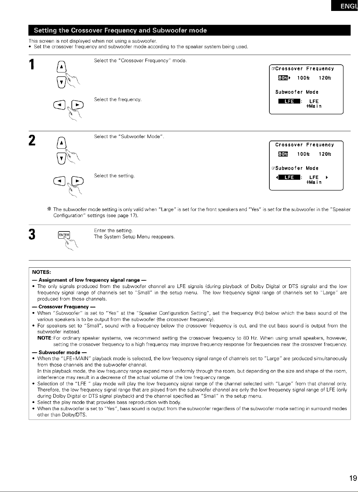
This screen is not displayed when not using a subwoofer.
• Set the crossover frequency and subwoofer mode according to the speaker system being used.
1
2
Select the "Crossover Frequency" mode.
_Crossover Frequency
i_ lOOHz 120Hz
Subwoofer Mode
Select the frequency.
Select the "Subwoofer Mode".
Select the setting.
The subwoofer mode setting is only valid when "Large" is set for the front speakers and "Yes" is set for the subwoofer in the "Speaker
Configuration" settings {see page 17).
Enter the setting.
The System Setup Menu reappears.
izr-J_l LFE
+Main
Crossover Frequency
I_ lOOHz 120Hz
_Subwoofer Mode
Iqi[:ll LFE
+Main
NOTES:
-- Assignment of low frequency signal range --
• The only signals produced from the subwoofer channel are LFE signals (during playback of Dolby Digital or DTS signals) and the low
frequency signal range of channels set to "Small" in the setup menu. The low frequency signal range of channels set to "Large" are
produced from those channels.
-- Crossover Frequency --
• When "Subwoofer" is set to "Yes" at the "Speaker Configuration Setting", set the frequency (Hz) below which the bass sound of the
various speakers is to be output from the subwoofer (the crossover frequency).
• For speakers set to "Small", sound with a frequency below the crossover frequency is cut, and the cut bass sound is output from the
subwoofer instead.
NOTE: For ordinary speaker systems, we recommend setting the crossover frequency to 80 Hz. When using small speakers, however,
setting the crossover frequency to a high frequency may improve frequency response for frequencies near the crossover frequency.
-- Subwoofer mode --
• When the "LFE+MAIN" playback mode is selected, the low frequency signal range of channels set to "Large" are produced simultaneously
from those channels and the subwoofer channel.
In this playback mode, the low frequency range expand more uniformly through the room, but depending on the size and shape of the room,
interference may result in a decrease of the actual volume of the low frequency range.
• Selection of the "LFE " play mode will play the low frequency signal range of the channel selected with "Large" from that channel only.
Therefore, the low frequency signal range that are played from the subwoofer channel are only the low frequency signal range of LFE (only
during Dolby Digital or DTS signal playback) and the channel specified as "Small" in the setup menu.
• Select the play mode that provides bass reproduction with body.
• When the subwoofer is set to "Yes", bass sound is output from the subwoofer regardless of the subwoofer mode setting in surround modes
other than Dolby/DTS.
Page 20
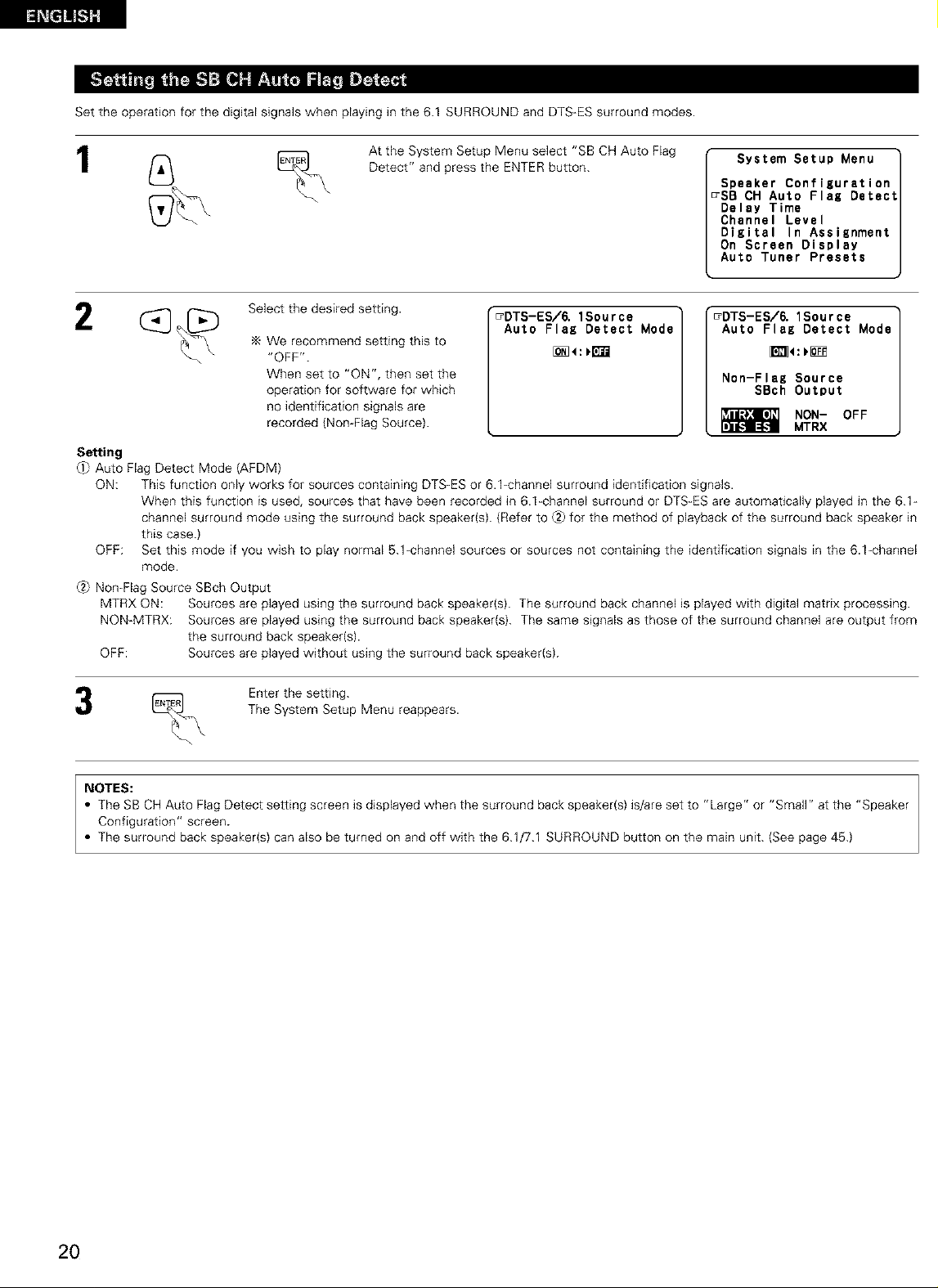
Settheoperationforthedigitalsignalswhenplayinginthe6.1SURROUNDandDTS-ESsurroundmodes.
1
Select the desired setting.
We recommend setting this to
"OFF".
When set to "ON", then set the
operation for software for which
no identification signals are
recorded {Non-Flag Source).
Setting
_ Auto Flag Detect Mode (AFDM)
ON: This function only works for sources containing DTS-ES or 6.1-channel surround identification signals.
When this function is used, sources that have been recorded in 6.1-channel surround or DTS-ES are automatically played in the 6.1-
channel surround mode using the surround back speaker{s). (Refer to _2_for the method of playback of the surround back speaker in
this case.)
OFF: Set this mode if you wish to play normal 5.1-channel sources or sources not containing the identification signals in the 6.1-channel
mode.
_2_Non-Flag Source SBch Output
MTRX ON: Sources are played using the surround back speaker(s). The surround back channel is played with digital matrix processing.
NON-MTRX: Sources are played using the surround back speaker{s). The same signals as those of the surround channel are output from
the surround back speaker(s).
OFF: Sources are played without using the surround back speaker(s).
At the System Setup Menu select "SB CH Auto Flag
Detect" and press the ENTER button.
_DTS-ES/6. 1Sour ce
Auto Flag Detect Mode
System Setup Menu
Speaker Configuration
_SB CH Auto Flag Detect
Delay Time
Channel Level
Digital In Assisnment
On Screen Display
Auto Tuner Presets
"_DTS-ES/6. 1Source
Auto Flag Detect Mode
Non-Flag Source
SBch Output
NON- OFF
MTRX
The System Setup Menu reappears.
_ Enter the setting.
NOTES:
• The SB CH Auto Flag Detect setting screen is displayed when the surround back speaker(s) is/are set to "Large" or "Small" at the "Speaker
Configuration" screen.
• The surround back speaker(s) can also be turned on and off with the 6.1/7.1 SURROUND button on the main unit. (See page 45.)
2O
Page 21
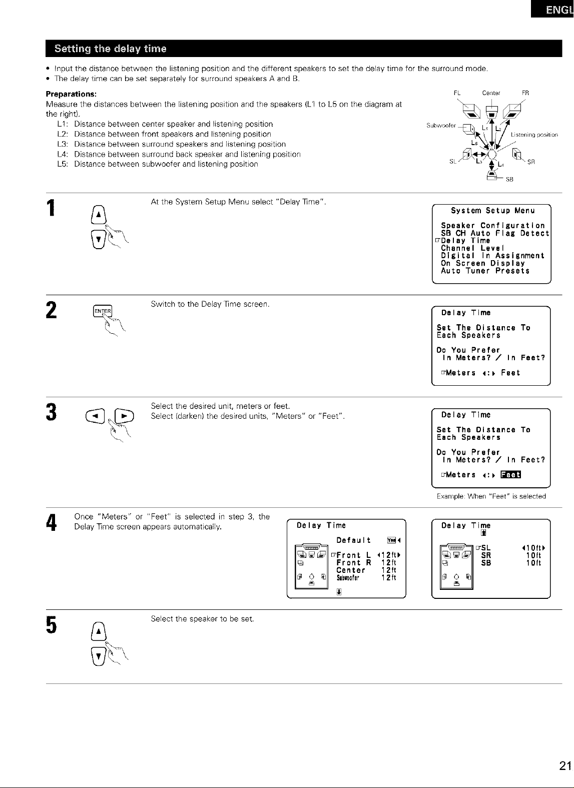
• input the distance between the listening position and the different speakers to set the delay time for the surround mode.
• The delay time can be set separately for surround speakers A and B.
Preparations:
Measure the distances between the listening position and the speakers (L1 to L5 on the diagram at
the right).
LI: Distance between center speaker and listening position
L2: Distance between front speakers and listening position
L3: Distance between surround speakers and listening position
L4: Distance between surround back speaker and listening position
L5: Distance between subwoofer and listening position
FL Center
Subwoofer
FR
SB
1
2
At the System Setup Menu select "Delay ]]me".
Switch to the Delay ]]me screen.
Select the desired unit, meters or feet.
Select (darken) the desired units, "Meters" or "Feet".
System Setup Menu
Speaker Configuration
SB CH Auto Flag Detect
_Delay Time
Channel Level
Digital In Assignment
On Screen Display
Auto Tuner Presets
Delay Time
Set The Distance To
Each Speakers
Do You Prefer
In Meters? / In Feet?
_Meters 4:_ Feet
Delay Time
Set The Distance To
Each Speakers
Do You Prefer
In Meters? / In Feet?
_Meters <:_
Once "Meters" or "Feet" is selected in step 3, the
Delay ]]me screen appears automatically.
Select the speaker to be set.
Delay Time
:rFront L <12ft_
Default _4
Center 12ft
Su_0fer 1 2 ft
Front R 12ft
Example: When "Feet" is selected
Delay Time
10ft
10ft
,lo,,,
Page 22
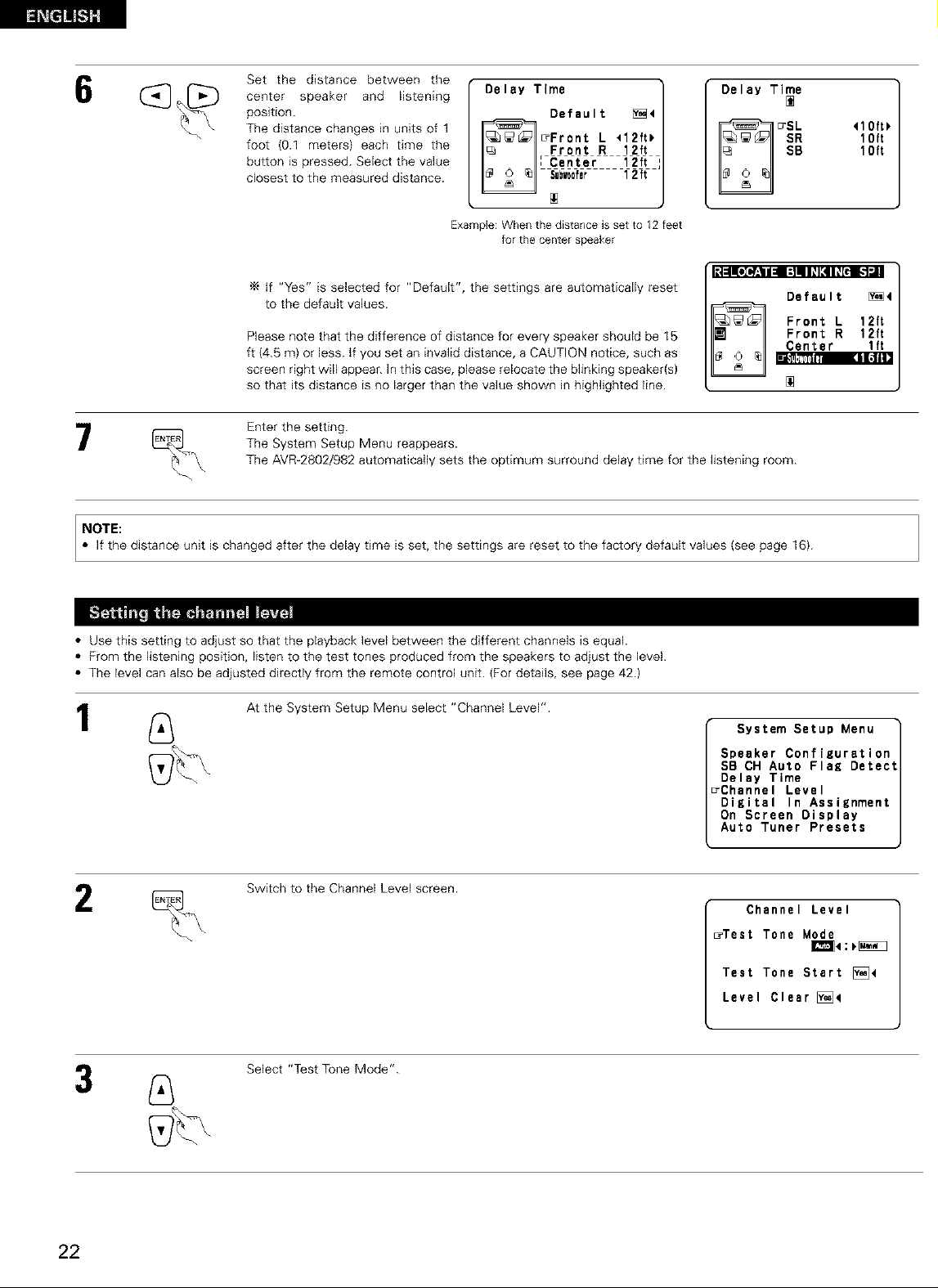
Setthedistancebetweenthe
centerspeakerand listening
position.
Thedistancechangesinunitsof1
foot(0.1meters)eachtimethe
buttonispressed.Selectthevalue
closesttothemeasureddistance.
Delay Time
[ Center 12ft I
_r f2tf
Default [_4
Front R 12ft
Front L 112ft_
Delay Time
10ft
10ft
Example:When the distanceis setto 12 feet
'_ if "Yes" is selected for "Default", the settings are automatically reset
to the default values.
Please note that the difference of distance for every speaker should be 15
ft {4.5 m) or less. If you set an invalid distance, a CAUTION notice, such as
screen right will appear. In this case, please relocate the blinking speaker{s)
so that its distance is no larger than the value shown in highlighted line.
Enter the setting.
The System Setup Menu reappears.
The AVR-2802/982 automatically sets the optimum surround delay time for the listening room.
NOTE:
• If the distance unit is changed after the delay time is set, the settings are reset to the factory default values (see page 16).
• Use this setting to adjust so that the ptayback level between the different channels is equal.
• From the listening position, listen to the test tones produced from the speakers to adjust the level.
• The level can also be adjusted directly from the remote control unit. (For details, see page 42.)
forthe centerspeaker
[_|:ll[eId:._lll=:]llllE41_[€l [-I_1
Center lft
BlII,,'?_ITI _1.1ill
Default [_4
Front R 12ft
Front L 12ft
2
At the System Setup Menu select "Channel Level".
Switch to the Channel Level screen.
Select "Test Tone Mode".
System Setup Menu
Speaker Configuration
SB CH Auto Flag Detect
Delay Time
rChannel Level
Digital In Assignment
On Screen Display
Auto Tuner Presets
Channel Level
_Test Tone Mode
Test Tone Start [_<
Level Clear [_<
22
Page 23
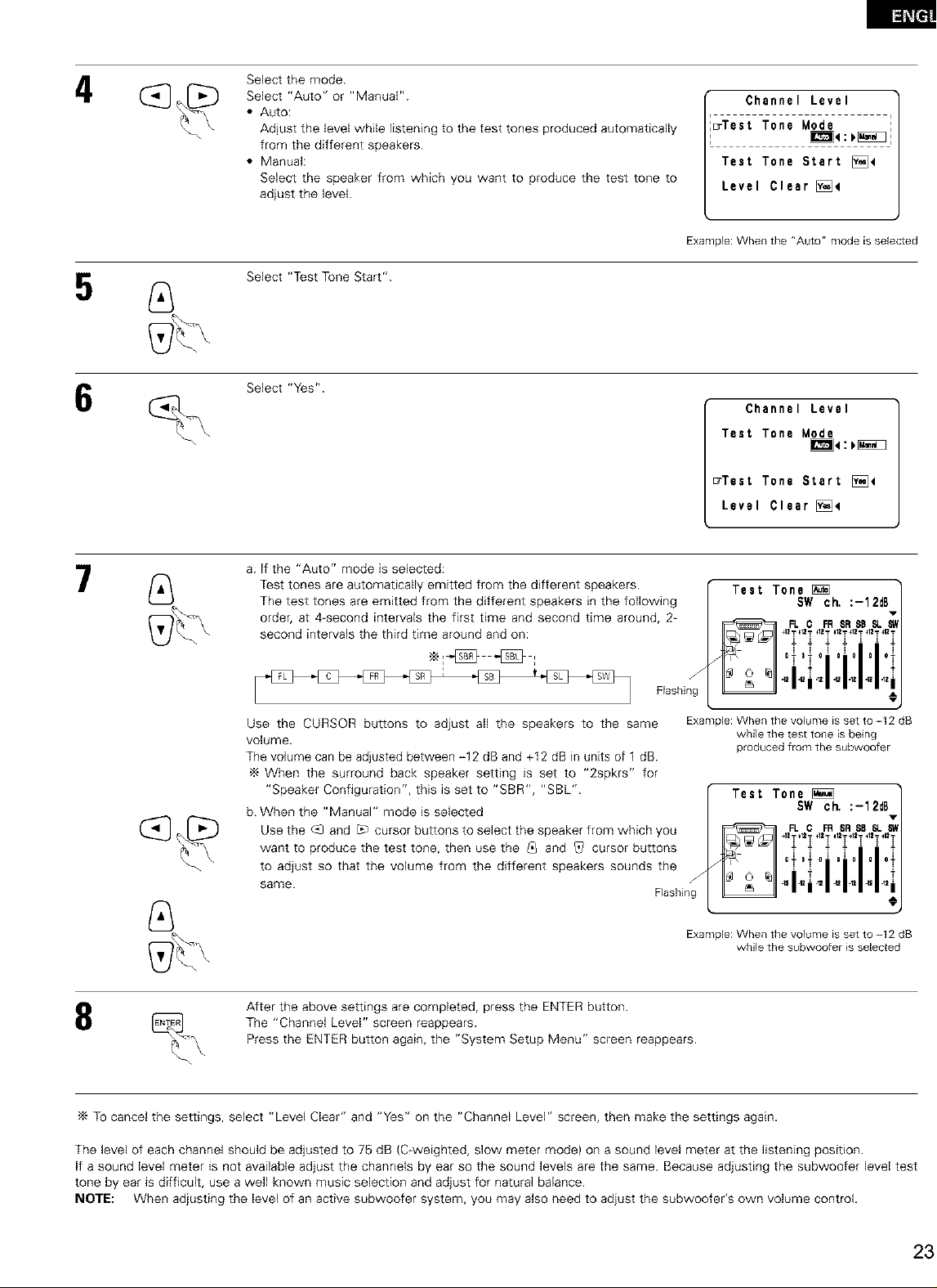
4
Select the mode.
Select "Auto" or "Manual".
• Auto:
Adjust the level while listening to the test tones produced automatically
from the different speakers.
• Manual:
Select the speaker from which you want to produce the test tone to
adjust the level.
Select "Test Tone Start".
Select "Yes".
Channel Level
_Test Tone Mode
Test Tone Start [_4
Level Clear [)_4
Example: When the "Auto" mode is selected
Channel Level
Test Tone Mode
_e:_
_Test Tone Start [_]4
Level Clear [_e
7
8
a. If the "Auto" mode is selected:
Test tones are automatically emitted from the different speakers.
The test tones are emitted from the different speakers in the following
order, at 4-second intervals the first time and second time around, 2-
second intervals the third time around and on:
Flashing
Use the CURSOR buttons to adjust all the speakers to the same
volume.
The volume can be adjusted between -12 dB and +12 dB in units of 1 dB.
When the surround back speaker setting is set to "2spkrs" for
"Speaker Configuration", this is set to "SBR", "SBL".
b. When the "Manual" mode is selected
Use the c_qand L_ cursor buttons to select the speaker from which you
want to produce the test tone, then use the _q and _ cursor buttons
to adjust so that the volume from the different speakers sounds the
same. Flashing
After the above settings are completed, press the ENTER button.
The "Channel Level" screen reappears.
Press the ENTER button again, the "System Setup Menu" screen reappears.
Test Tone
f
Example: When the volume is set to -12 dB
while the test tone is being
produced from the subwoofer
Test Tone
J
Example: When the volume is set to -12 dB
while the subwoofer is selected
SW ch, :-12d6
+1ZT_I2T _12T _12T_12T +1ZT_12T
---- i i -
i'0"oi01o i o"
°;;ii
41 -t2 .12 .t2 42 42 42
SW ch. :-12d8
+i.........i
O
To cancel the settings, select "Level Clear" and "Yes" on the "Channel Level" screen, then make the settings again.
The level of each channel should be adjusted to 75 dB (C-weighted, slow meter mode) on a sound level meter at the listening position.
If a sound level meter is not available adjust the channels by ear so the sound levels are the same. Because adjusting the subwoofer level test
tone by ear is difficult, use a well known music selection and adjust for natural balance.
NOTE: When adjusting the level of an active subwoofer system, you may also need to adjust the subwoofer's own volume control.
Page 24
Whenyouadjustthechannellevelswhilein the SYSTEM SETUP CHANNEL LEVEL mode, the channel level adjustments made wifl affect
ALL surround modes. Consider this mode a Master Channel Level adjustment mode.
After you have completed the SYSTEM SETUP CHANNEL LEVEL adjustments, you can then activate the individual surround modes and
adjust channel levels that wifl be remembered for each of those modes. Then, whenever you activate a particular surround sound mode,
your preferred channel level adjustments for just that mode will be recalled. Check the instructions for adjusting channel levels within each
surround mode on Page 42.
You can adjust the channel levels for each of the following surround modes: DIRECT, STEREO, 5CH/6CH STEREO, DOLBY/DTS
SURROUND, ROCK ARENA, JAZZ CLUB, VIDEO GAME, MONO MOVIE, and MATRIX.
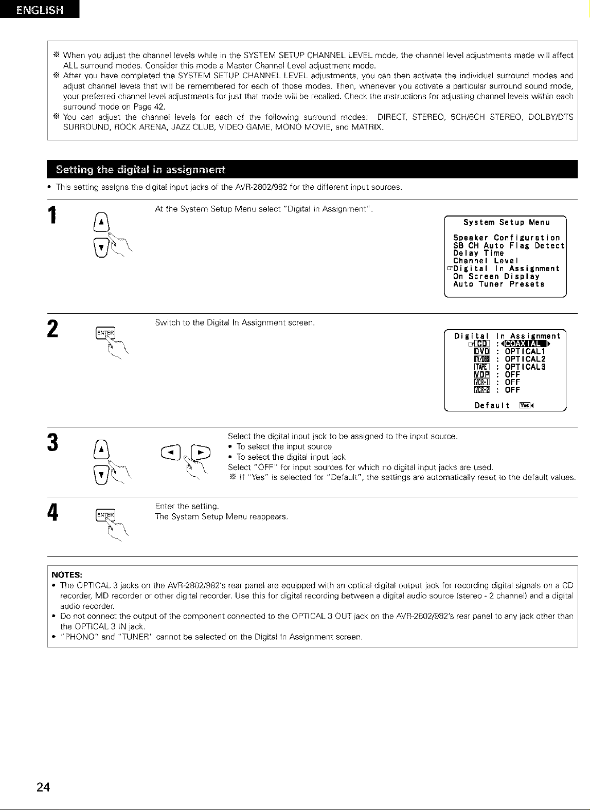
• This setting assigns the digital input jacks of the AVR-2802/982 for the different input sources.
1
2
At the System Setup Menu select "Digital In Assignment".
System Setup Menu
Speaker Configuration
SB CH Auto Flag Detect
Delay Time
Channel Level
_Digital In Assignment
On Screen Display
Auto Tuner Presets
Switch to the Digital In Assignment screen.
Digital In Assignment
[_ OPTICAL3
[_ OFF
[_ OFF
Default [_<
Select the digital input jack to be assigned to the input source.
_ Select "OFF" for input sources for which no digital input jacks are used.
(_ _ • To select the input source
• To select the digital input jack
if "Yes" is selected for "Default", the settings are automatically reset to the default values.
OPTICAL1
OPTICAL2
OFF
The System Setup Menu reappears.
_--_ Enter the setting.
NOTES:
• The OPTICAL 3 jacks on the AVR 2802/982's rear panel are equipped with an optical digital output jack for recording digital signals on a CD
recorder, MD recorder or other digital recorder. Use this for digital recording between a digital audio source (stereo 2 channel) and a digital
audio recorder.
• Do not connect the output of the component connected to the OPTICAL 3 OUT jack on the AVR-2802/982's rear panel to any jack other than
the OPTICAL 3 IN jack.
• "PHONe" and "TUNER" cannot be selected on the Digital in Assignment screen.
24
Page 25
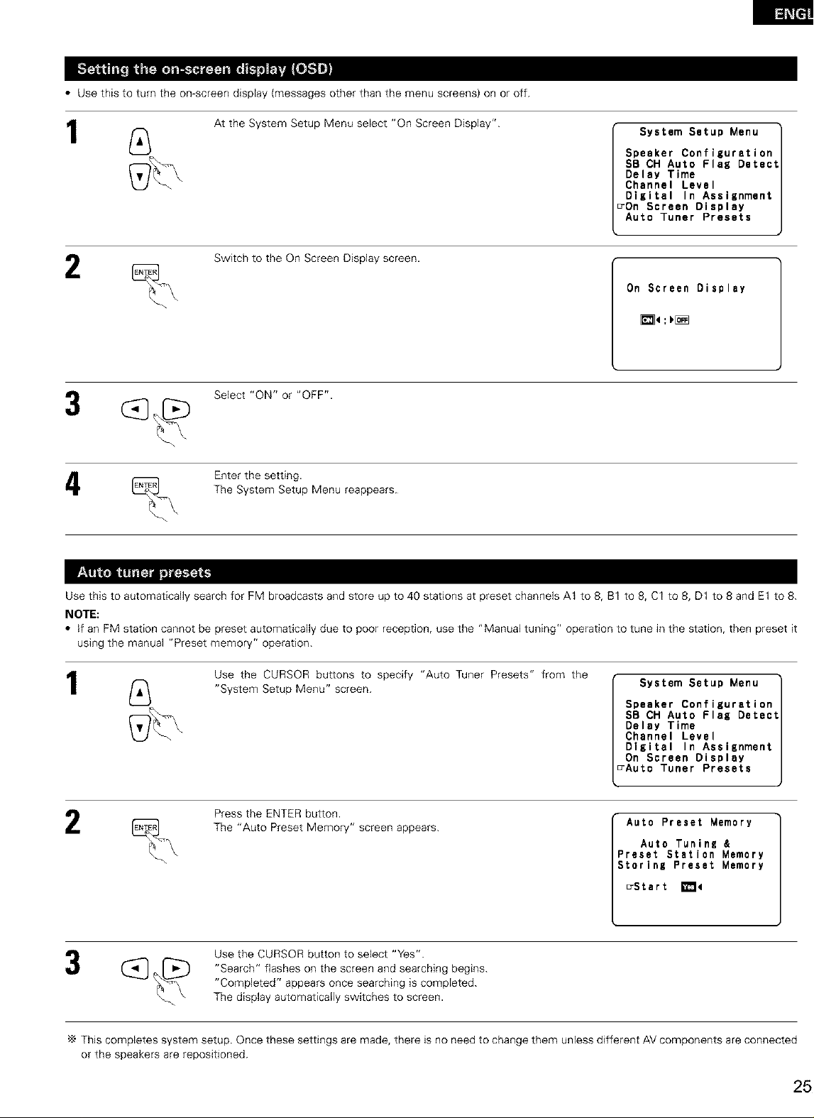
• Use this to turn the on-screen display {messages other than the menu screens) on or off.
1
2
At the System Setup Menu select "On Screen Display".
Switch to the On Screen Display screen.
Select "ON" or "OFF".
The System Setup Menu reappears.
% Enter the setting.
System Setup Menu
Speaker Configuration
SB CH Auto Flag Detect
Delay Time
Channel Level
Digital In Assignment
DOn Screen Display
Auto Tuner Presets
On Screen Display
_4:_[_
Use this to automatically search for FM broadcasts and store up to 40 stations at preset channels A1 to 8, B1 to 8, C1 to 8, D1 to 8 and E1 to 8.
NOTE:
• if an FM station cannot be preset automatically due to poor reception, use the "Manual tuning" operation to tune in the station, then preset it
using the manual "Preset memory" operation.
1
2
Use the CURSOR buttons to specify "Auto Tuner Presets" from the
"System Setup Menu" screen.
Press the ENTER button.
The "Auto Preset Memory" screen appears.
Use the CURSOR button to select "Yes".
"Search" flashes on the screen and searching begins.
"Completed" appears once searching is completed.
The display automatically switches to screen.
System Setup Menu
Speaker Configuration
SB OH Auto Flag Detect
Delay Time
Channel Level
Digital In Assignment
On Screen Display
_Auto Tuner Presets
Auto Preset Memory
Auto Tuning &
_reset Station Memory
Storing Preset Memory
_Stert _4
This completes system setup. Once these settings are made, there is no need to change them unless different AV components are connected
or the speakers are repositioned.
Page 26
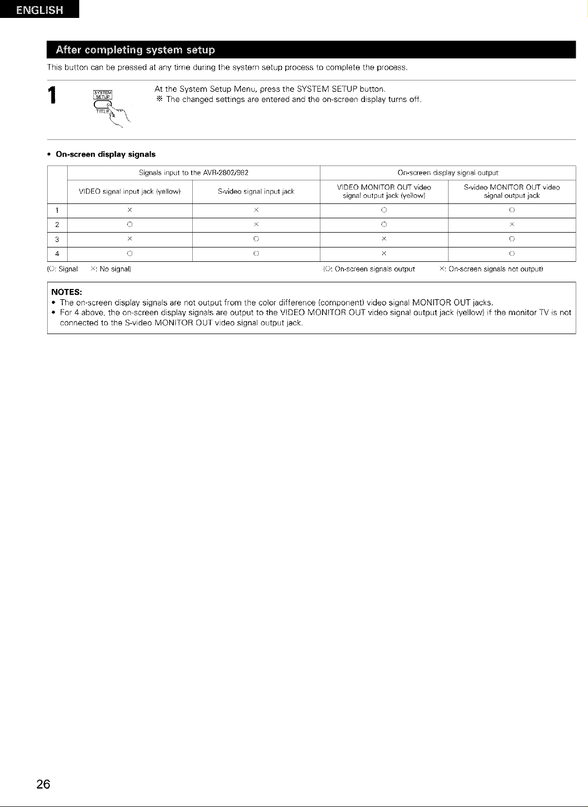
Thisbuttoncanbepressedatanytimeduringthesystemsetupprocesstocompletetheprocess.
AttheSystemSetupMenu,presstheSYSTEMSETUPbutton.
Thechangedsettingsareenteredandtheon-screendisplayturnsoff.
• On-screen display signals
Signals input to the AVR-2802/982 On-screendisplay signaloutput
VIDEOsignal input iack (yellow) S-videosignal input jack signal output jack {yellowl signal output iack
I x × C) (}
2 o × o ×
3 x (} x (}
4 0 (} x (}
((}: Signal x: No signal) (}: On-screen signals output x: On-screen signals not output)
NOTES:
• The on screen display signals are not output from the color difference (component) video signal MONITOR OUT jacks.
• For 4 above, the on-screen display signals are output to the VIDEO MONITOR OUT video signal output jack (yellow) if the monitor TV is not
connected to the S-video MONITOR OUT video signal output jack.
VIDEO MONITOR OUTvideo S-video MONITOR OUTvideo
26
Page 27
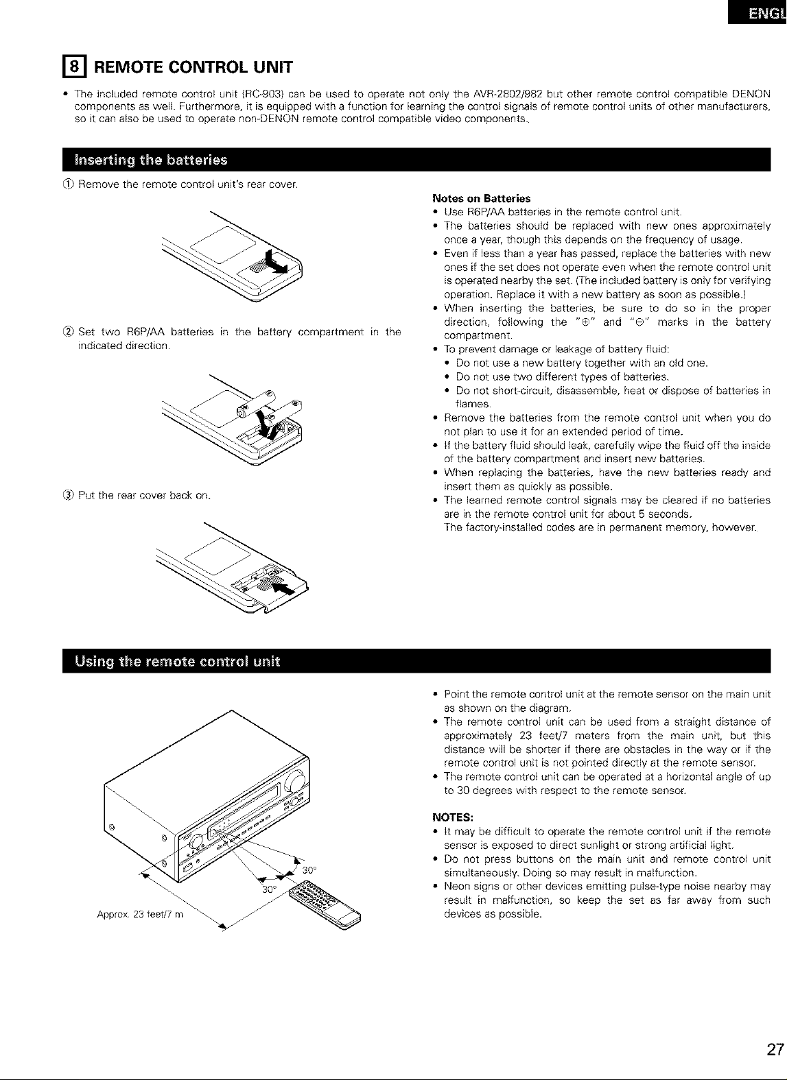
[] REMOTE CONTROL UNIT
• The included remote control unit (RC 903) can be used to operate not only the AVR-2802/982 but other remote control compatible DENON
components as well. Furthermore, it is equipped with a function for learning the control signals of remote control units of other manufacturers,
so it can also be used to operate nomDENON remote control compatible video components.
_ Remove the remote control unit's rear cover.
Notes on Batteries
• Use R6P/AA batteries in the remote control unit.
• The batteries should be replaced with new ones approximately
once a year, though this depends on the frequency of usage.
• Even if less than a year has passed, replace the batteries with new
ones if the set does not operate even when the remote control unit
is operated nearby the set. (The included battery is only for venfying
operation. Replace it with a new battery as soon as possible.)
• When inserting the batteries, be sure to do so in the proper
@ Set two R6P/AA batteries in the battery compartment in the
indicated direction.
@ Put the rear cover back on.
direction, following the "O" and "0" marks in the battery
compartment.
• To prevent damage or leakage of battery fluid:
• Do not use a new battery together with an old one.
• Do not use two different types of batteries.
• Do not short-circuit, disassemble, heat or dispose of batteries in
flames.
• Remove the batteries from the remote control unit when you do
not plan to use it for an extended period of time.
• if the battery fluid should leak, carefully wipe the fluid off the inside
of the battery compartment and insert new batteries.
• When replacing the batteries, have the new batteries ready and
insert them as quickly as possible.
• The learned remote control signals may be cleared if no batteries
are in the remote control unit for about 5 seconds.
The factory-installed codes are in permanent memory, however.
_ 30°
Approx 23 feet/7 m _
• Point the remote control unit at the remote sensor on the main unit
as shown on the diagram.
• The remote control unit can be used from a straight distance of
approximately 23 feet/7 meters from the main unit, but this
distance will be shorter if there are obstacles in the way or if the
remote control unit is not pointed directly at the remote sensor.
• The remote control unit can be operated at a horizontal angle of up
to 30 degrees with respect to the remote sensor.
NOTES:
• it may be difficult to operate the remote control unit if the remote
sensor is exposed to direct sunlight or strong artificial light.
• De not press buttons on the main unit and remote control unit
simultaneously. Doing so may result in malfunction.
• Neon signs or other devices emitting pulse-type noise nearby may
result in malfunction, so keep the set as far away from such
devices as possible.
Page 28

• Turnonthepowerofthedifferentcomponentsbeforeoperatingthem.
Set mode switch 1 to "AUDIO (AVR/AVC)".
1
Set mode switch 2 to the position for the component to be
operated.
Operate the audio component.
• For details, refer to the component's operating instructions.
While this remote control is compatible with a wide range of infrared controlled components, some models of components may not
be operated with this remote control.
t, CD player (CD) and CD recorder and MD recorder (CDR/MD)
system buttons
AUDIO
AVR]AVC VIDEO
TAPE CDR/MD
CD_ ,t,t-MULTI
_'TT_
VDP VCR
1
3
2. Tape deck (TAPE) s stem buttons
@ ©
2
0
441, _1_ : Manual search (forward and reverse}
• : Stop
I_ : Play
1414, _ : Auto search (cue)
II : Pause
DISC : Switch discs
SKIP+ (for CD changers only)
3, Tuner system buttons
SHIFT : Switch preset channel range
CHANNEL : Preset channel
+, - up/down
<_1 : Rewind
_1_ : Fast_orward
• : Stop
I_ : Forward play
|| : Pause
_<l : Reverse play
A/B : Switch between decks A and B
For the tuner only, the following buttons can also be operated:
TUNING Frequency
&, • up/down
BAND Switch between the AM and FM bands
MODE Switch between auto and mono
MEMORY Preset memory
28
Page 29
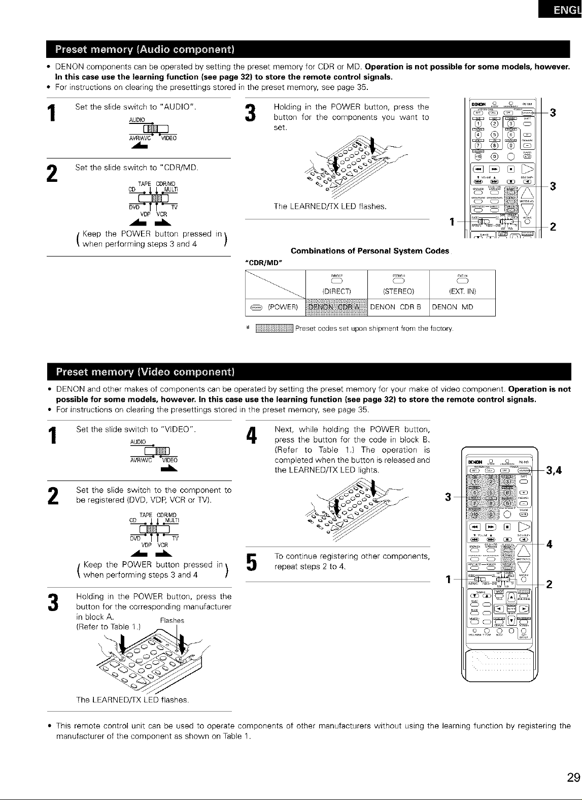
• DENON components can be operated by setting the preset memory for CDR or MD. Operation is not possible for some models, however.
in this case use the learning function (see page 32) to store the remote control signals.
• For instructions on clearing the presettJngs stored in the preset memory, see page 35.
Set the slide switch to "AUDIO".
1
AUDIO
Holding in the POWER button, press the
3
button for the components you want to
set.
3
_@0_
Set the slide switch to "CDR/MD.
2
TAPE CDPdMD
cD li MULT_I
_ f f'_
V_ VCR
The LEARNED/TX LED flashes.
1
Keep the POWER button pressed in
when performing steps 3 and 4 /
"CDR/MD"
• DENON and other makes of components can be operated by setting the preset memory for your make of video component. Operation is not
possible for some models, however, in this case use the learning function (see page 32) to store the remote control signals.
• For instructions on clearing the presettings stored in the preset memory, see page 35.
Combinations of Personal System Codes
c? c?
_. (DIRECT) (STEREO) (EXT IN)
/POWERIENON'CD DENONCDRBDENONMD
1111111
Preset codes set upon shipment from the factory
_._1_ _1
3
2
Set the slide switch to "VIDEO".
1
Set the slide switch to the component to
be registered (DVD, VDP, VCR or TV}.
Keep the POWER button pressed in
when performing steps 3 and 4 /
Holding in the POWER button, press the
button for the corresponding manufacturer
in block A. Flashes
(Refe_
The LEARNED/TX LED flashes.
AUDIO
AVPdAVC VIDEO
TAPE CDR/MD
CD _li MULTI
VDP VCR
Next, while holding the POWER button,
4
press the button for the code in block B.
(Refer to Table 1.) The operation is
completed when the button is released and
the LEARNED/TX LED lights.
3,4
3
4
To continue registering other components,
\
repeat steps 2 to 4.
x/
2
_%o o o
• This remote control unit can be used to operate components of other manufacturers without using the learning function by registering the
manufacturer of the component as shown on Table 1.
Page 30
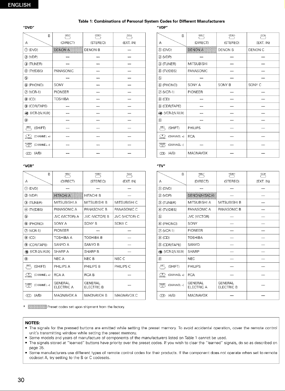
Table 1: Combinations of Personal System Codes for Different Manufacturers
"DVD"
( }
(DIRECT)
@ {DVDI
S_r4L_
(STEREO)
DENON B
{EXT IN)
{8 (VDP)
@ (TUNER)
(4} {TV/DBS)
PANASONIC
®
{6) (PHONO)
[7) (VCR-1)
® (CD)
® (CDR/TAPE)
@ (VCR-2A/AUX)
SONY
PIONEER
TOSHIBA
@
(SHIFT)
c_ (CHANNEL+)
c_ (CHANNEL-}
(A/B)
"VCR"
S_r4L_
(DIRECT) {EXT IN)
® (DVDI
{2)(VDP)
_.s)(TUNER)
(4) {TV/DBS)
®
{6) (PHONO)
{7) (VCR-11
® (CDI
® (CDR/TAPE)
@ (VCR-2A/AUX)
@
(SHIFT)
c_ (CHANNEL÷)
_ (CHANNEL-} ---
@ (A/B) MAGNAVOX C
MFSUBISHI A
PANASONIC A
JVC (VICTOR) A
SONY A
PIONEER
TOSHIBA A
SANYO A
SHARP A
NEC A
PHILPS A
RCA A
GENERAL
ELECTRIC A
MAGNAVOX A
(STEREO)
HITACHI B
MITSUBISHI B
PANASONIC B
JVC (VICTOR) B
SONY B
TOSHIBA B
SANYO B
SHARP B
NEC B
PHILIPS B
RCA B
GENERAL
ELECTRIC B
MAGNAVOX B
MITSUBISHI C
PANASONIC C
JVC {VICTOR) C
SONY C
NEC C
PHILIPS C
"VDP"
O
(DIRECT)
® (DVDI
(STEREO)
DENON B
DENON C
[2)IVDP)
(.s}(TUNER)
(4) {TV/DBS)
MFSUBISHI
PANASONIC
®
® (PHONO)
{8 (VCRq)
® (CDI
® (CDR/TAPE)
@ (VCR-2A/AUX)
}ONY A
PIONEER
SONY B
SONY C
@
(SHIFT)
_L (CHANNEL+}
_L (CHANNEL-}
(A/B)
® (DVD)
® (VDP)
@ (TUNER)
® {TV/DBSI
®
{6) (PHONO)
{8 (VCRql
® (CDI
® (CDR/TAPE)
@ (VCR-2A/AUX)
@
(SHIFT)
C_L (CHANNEL+}
_""L_)L (CHANNEL"} ELECTRIC A
@ (A/B) MAGNAVOX --
PHILPS
RCA
MAGNAVOX
(DIRECT)
MFSUBISHI A
PANASONIC A
JVC (VICTOR)
}ONY
PIONEER
TOSHIBA
}ANYO
}HARP
NEC
PHILPS
RCA
GENERAL
MITSUBISHI B
PANASONIC B
GENERAL
ELECTRIC B
(EXT IN)
m
m
m
m
m
m
m
m
m
{EXT IN)(STEREO)
* Preset codes set upon shipment from the factory
NOTES:
The signals for the pressed buttons are emitted while setting the preset memory. To avoid accidental operation, cover the remote control
unit's transmitting window while setting the preset memory.
Some models and years of manufacture of components of the manufacturers listed on Table 1 cannot be used.
The signals stored at "learned" buttons have priority over the preset codes. If you wish to clear the "learned" signals, do so as described on
page 35.
Some manufacturers use different types of remote control codes for their products. )f the component does not operate when set to remote
codeset A, try setting to the B or C codesets.
3O
Page 31

Set the slide switch to "VIDEO".
IL
Set the slide switch to the component to be registered (DVD,
VDP, VCR or TV).
T_E CD_MD
CD.11_MULTI
_tt_
VDP VCR
Operate the video component.
• For details, refer to the component's operating instructions.
"_ Some models cannot be operated with this remote control unit.
I. DVD player system buttons
POWER : Turns power on and off MENU : Call out menu
(ON/SOURCE) DISPLAY : Switch display
_1_1,1_ : Manual search (forward and reverse) DVD SET UP: DVD setup
• : Stop RETURN : Menu return
@ @ @ c_
@ ® ©
I_ : Play _,'_ : Cursor up/down
I_1,1_1_1 : Auto search (cue) _1,1_ : Cursor left/right
n : Pause SELECT : Enter setting
SKIP + : (for DVD changers only)
TITLE : Call out title
3
0 CD CD
0 CD CD ..........
/,,
o Ao, o_
NOTE:
Some manufacturers use different names for the DVD remote control buttons, so also refer to the instructions on
remote control for that component
2, Video disc player {VDP) system 3 Video _eck {VCR) system 4. Monito_ TV system buttons
buttons
@ @ @ c_
POWER : Power on/off
(ON/SOURCE)
_l_l,l_l_ : Manual search
(forward and reverse)
• : Stop
I_ : Play
I_1_1,1_1_1 : Auto search (cuel
n : Pause
buttons
@ @ @ _
@ ® ©
POWER : Power on/off
(ON/SOURCE)
_,1_ : Manual search
(forward and reverse)
• : Stop
I_ : Play
II : Pause
CHANNEL : Switch channel
+,-
® @ @ c_
@ ® ©
• _UaE • b_cs_p_
POWER : Power on/off
{ON/SOURCE)
VOLUME : Volume
A,Y up/down
TVNCR : Switch between TV
and VCR
CHANNEL : Switch channel
+,-
Page 32

• if your AV component is not a DENON product or it cannot be operated with the preset memory codesets, you can "teach" the AVR-2802/982'S
remote control to "learn" the codes from the component's original remote control.
• The buttons that can be "learned" are the CD, TAPE and CDR/MD system buttons (see page 28) and
the DVD, VDP, VCR and TV system buttons {see page 31). (For the CD, CDR/MD, DVD, VDP and TV, the
A block buttons can also be "learned", and for the DVD and TV, the B block buttons can also be
"learned".)
Press the USE/LEARN selector button with the tip of a pen
1
etc., to set the learn mode. Both the START and LEARNED/TX
indicators flash. Hashes
This unit's remote
control unit
Set the program switch to the side to be learned.
2
Set to the AUDIO side for the CD, tape deck or CDR/MD
position, to the VIDEO side for the DVD, VDP, VCR or TV
position.
Set the program switch to the position to be learned.
AUDIO
_ v'_Ng
T_E CD_MD
cD __MULTI
_TT_
VDP VCR
Check that the START LED is lit, then press the button to be
"learned" on the other remote control unit.
set the remote control units so they are facing each other,
then press the button to be learned on this unit's remote
control unit.
The indicator stops flashing and the START LED lights.
The learnable buttons are the buttons which can be operated
with the DENON system codes for the CD player, tape deck,
CD recorder, MD recorder, the buttons which can be operated
with the preset memory for the DVD, VCR, VDP and TV. For
the TV only, however, the buttons in the section indicated "A"
on the diagram above can also be "learned". Use these to
"learn" TV channels.
NOTES:
• Up to 26 codes can be "learned", but this number may be lower if the codes are long.
• If a nonqearnable button is pressed or two or more buttons are pressed at once, the two LEDs will once again light when the button{s)
is released.
• If the codes could not be stored, the LEARNEDfrX LED does not light after the START LED turns off. For limited number of models, codes
cannot be stored in RC-903.
• If the two LEDs start flashing rapidly after the START LED lights, this means that the memory is already full, and the code you have just
attempted to store was not stored.
To "learn" that code, first perform the resetting operation. {See page 35.)
Transmitting windows Othelremote
c°ntr°l unit
Light,\\\\
Once the START LED turns off and the LEARNEDfrX LED
lights, release the button on the other remote control unit.
The two LEDs start
flashing again Light
To "learn" other buttons, repeat steps 2 to 6.
Once the learning operation is completed, press the
8
USE/LEARN selector button again.
The two LEDs stop flashing and the learning mode is
cancelled. _ twha_ktheoptOrrl_!
32
Page 33

• The included remote control unit is equipped with a system call function for transmitting multiple remote control signals when a single button
is pressed {this is often referred to as a "macro" function).
This function can be used to turn on the amplifier's power, select the input source, turn on the monitor TV's power, turn on a source
component's power and start playback, etc., all at the touch of a button.
(1) System call buttons
The buttons that can be used for the system call function are shown on the table below.
A series of up to 10 operations can be performed with the POWER ON and OFF buttons, and a series of up to 5 operations can be performed
with other buttons.
System call signals are already preset at the buttons indicated in the shaded section. System call signals can also be stored at any button on
the remote control unit, including the buttons in this section. (See page 34.)
Button
POWER OFF
NO
transmiss]ons
10
Stored
operation 1
Stored Stored Stored
operation 2 operation 3 operation 4
Stored
operation 5
Stored
operadon 6
Stored Stored
operadon 7 operation 8
Stored Stored
operation 9 operation /0
POWER QN
DVD
VDP
TV/DBS
VCR 1
CD
10
5
5
5
5
5
Receiver
power on
Receiver
power on
Receiver
power on
Receiver
power on
Receiver
power on
DVD player Receiver
(DVD) switched to
power on DVD
LD player Receiver
(VDP) switched to
poweron VDP
TVpoweron
Vldeo(VCR) inputsource TV poweton
poweron switchedto
Receiver
i_put source
switched to
input source
input source
input source
switched to
CD
(2) Using the system call function
Press the system call button.
1
• The LEARNED/TX LED flashes for 5 seconds.
Press the button at which the desired system call signals are
stored while the LEARNED/TX LED is flashing.
• The preset signals or the signals you have stored at that
button are transmitted in succession.
Recelver
TV/DBS
Receiver
VCR /
TV power on
TV power on
DVD player
{DVD)
playback
LD player
{VDP)
playback
Video (VCR)
playback
The system call signals for the POWER OFF and
POWER ON buttons are transmitted from the
remote control unit approximately once every
second.
The signals for the other buttons (DVD, VDP, TV /
DBS, VCR-1 and CD) are transmitted approximately
once every 1.5 seconds.
1
2
@@0_
2-
Page 34

(3) Storing signals (4} Clearing system call settings
1,3
2
@@0_
3
>.- ._
Press the SET button.
• The START LED and LEARNED/TX LED both flash.
Press the button at which you want to store the system call
signals.
• The START LED flashes.
Set the mode switch to the position for the component
whose remote control signals you want to store.
@@0@
pwo ,o o_
Press the SET button.
Press the button whose settings you want to clear.
Press the SET button.
• The button is reset to the settings shown on the table on
page 33.
TAPE CDPJMD
.A----L vDPVCR
Press the buttons whose remote control signals you want to
store one by one.
Press the SET button.
NOTES:
• The remote control signals for the buttons pressed while storing the system call signals are transmitted when the buttons are pressed, so
cover the remote sensor or take other measures so that the components do not operate while the signals are being stored.
• The LEARNEDfTX LED does not light if system call signals cannot be stored at the button that you have pressed or if you have already stored
the maximum number of signals.
34
Page 35

4
To clear "learned" remote control signals, set the slide switch
to the position at which the signals were "learned".
AUDIO
®os
Set the slide switch to the position at which the signals were
( }
2
3
"learned".
T_E CD_MD
D_Y'TT_
VDP VCR
1,5 _o o o
Press the USE/LEARN selector button with the tip of a pen,
1
etc., to set the learn mode.
[] OPERATION
Refer to "CONNECTIONS" (pages 6 to 13) and check that all
connections are correct.
Set the remote control unit's slide AUO_O
SWitCh tO the AUDIO position. (only
when operating with the remote
control unit)
Turn on the power.
Press the POWER switch (button).
oN JSTANDBy
ON/STANDBY
Press the SYSTEM CALL SET button, and hold it in for at least
4
four seconds.
• When both the START and LEARNEDfrX LEDs light
simultaneously, all the stored codes are cleared.
@h
Press the USE/LEARN selector button.
(Mainurlit) (Remotecontrolunit)
When pressed, the power turns on and the display lights. The sound
is muted for several seconds, after which the unit operates normally.
When pressed again, the power turns off, the standby mode is set
and the display turns off.
Whenever the ON/STANDBY button is in the STANDBY state, the
apparatus is still connected on AC line voltage. Please be sure to
unplug the cord when you leave home for, say, a vacation.
Select the front speakers.
4
Press SPEAKER A or B turn the speaker on.
SPEAKER
O O
A m SPEAKER
@@0_
4 _ _ 5 _
2
Page 36

1 3 5
_ _ o o
2
Select the input source to be played.
1
Example: CD
(Main unit} (Remote cor}trol unit)
To select the input source when REC SOURCE
selected, press the SOURCE button
/MULTI OUT or TUNING PRESET is '_'(_ \
then operate the input function
selector.
Select the input mode.
• Selecting the analog mode
Press the ANALOG button to switch to the analog input.
ANALOG
(Main unit) (Remote control unit)
• Selecting the external input (EXT. IN) mode
Press the EXT. IN to switch the external input.
EXTIN
(Mainunit} (Remotecontrolunit)
• Selecting the AUTO, PCM and DTS modes
The mode switches as shown below each time the INPUT
MODE button is pressed.
AUTO _ PCM _ DTS
ANALOG
E×TEN
(Maill unit)
3
5
2_
Input mode selection function
Different input modes can be selected for the different input sources.
The selected input modes for the separate input sources are stored in
the memory.
(_ AUTO (auto mode)
in this mode, the types of signals being input to the digital and
analog input jacks for the selected input source are detected and
the program in the AVR-2802/982'S surround decoder is selected
automatically upon playback. This mode can be selected for all
input sources other than PHONO and TUNER.
The presence or absence of digital signals is detected, the signals
input to the digital input jacks are identified and decoding and
playback are performed automatically in DTS, Dolby Digital or PCM
(2 channel stereo) format. If no digital signal is being input, the
analog input jacks are selected.
Use this mode to play Dolby Digital signals.
_) PCM (exclusive PCM signal playback mode)
Decoding and playback are only performed when PCM signals are
being input.
Note that noise may be generated when using this mode to play
signals other than PCM signals.
(_ DTS (exclusive DTS signal playback mode)
Decoding and playback are only performed when DTS signals are
being input.
(_ ANALOG (exclusive analog audio signal playback mode)
The signals input to the analog input jacks are decoded and played.
_) EXT. IN (external decoder input jack selection mode)
The signals being input to the external decoder input jacks are
played without passing through the surround circuitry.
NOTE:
• Note that noise will be output when CDs or LDs recorded in DTS
format are played in the "PCM" {exclusive PCM signal playback) or
"ANALOG" {exclusive PCM signal playback) mode. Select the
AUTO or DTS mode when playing signals recorded in DTS from a
laser disc player or CD player.
Note on playing a source encorded with DTS
• Noise may be generated at the beginning of playback and
while searching during DTS playback in the AUTO mode, If
so, play in the DTS mode.
36
INPUt MODE
(Main unit} (Remote control unit)
INPUT MODE
Page 37

Select the play mode.
Press the SURROUND MODE button, then turn the SELECT
knob.
Example: Stereo
SURROUND SELECT
MODE ST£REO
(Main unit) {Remote cont ro_ unit)
TO select the surround mode while adjusting the surround
parameters, channel volume or tone control, press the surround
mode button then operate the selector.
SURROUND
MODE
Input mode display
• in the AUTO mode
_UT9 PCM DTS
/i \
INPUT
o o o
• in the DIGITAL PCM mode
_N_UT
AUTO \p¢_ eTS
o o o
/i \
• in the DIGITAL DTS mode
_N_UT
AUTO PCM @TS_
o o o
• in the ANALOG mode
AUTO pCM DTS
INPUT
o o o
One of these Hghts, depending on the
input slgna_
/i _
{Mainunit)
Start playback on the selected component.
• For operating instructions, refer to the component's
manual.
Adjust the volume.
tO_ MAS ERV0 UME
The volume level is {Main unit) {Remote control unit)
displayed on the master
volume level display
The volume can be adjusted within the range of -70 to 0 to 18 dB,
in steps of 1 dB. However, when the channel level is set as
described on page 22 or pages 42 and 43, if the volume for any
channel is set at +1 dB or greater, the volume cannot be adjusted
up to 18 dB. {In this case the maximum volume adjustment range
is "18 dB -- {Maximum value of channel level)".}
Input mode when playing DTS sources
• Noise will be output if DTS compatible CDs or LDs are played in the
"ANALOG" or "PCM" mode.
When playing DTS-compatible sources, be sure to connect the
source component to the digital input jacks (OPTICAL/COAXIAL}
and set the input mode to "DTS'.
Input signal display
• DOLBY DIGITAL
SIGN&L
O
• DTS
• PCM
0 0
,_ The _ indicator lights when digital signals are being input
properly. If the _ indicator does not light, check whether
the digital input component setup {page 24) and connections are
correct and whether the component's power is turned on.
NOTE:
• The _ indicator will light when playing CD-ROMs
containing data other than audio signals, but no sound will be
heard.
Page 38

Set the external input (EXT.
1
IN} mode.
Press the EXT. IN to swkch
the external input.
Once this is selected, the input signals connected to the FL
(front left), FR (front nght) and C (center) channels of the EXT.
IN jacks are output directly to the front (left and right) and
center speaker systems as well as the pre-out jacks without
passing through the surround circuitry.
in addition, the signal input to the SW {subwoofer) jack is
output to the PRE OUT SUBWOOFER jack.
EXT_N
{Main unit} (Remote control unit}
EXT EN
0[,,,
@ o o o
D_
zOZ
2 1
Cancelling the external input mode
2
To cancel the external input (EXT. IN) setting, press the INPUT
MODE (AUTO, PCM, DTS) or ANALOG button to switch to
the desired input mode• (See page 36•)
INPUT MODE ANALOG
INPUT MODE ANALOG
%%
(Main unit)
• When the input mode is set to the external input (EXT. IN), the play
mode (DIRECT, STEREO, DOLBY/DTS SURROUND, 5CH/6CH
STEREO or DSP SIMULATION) cannot be set.
[1] Adjusting the sound quality (tone)
The tone control function will not work in the direct mode•
The tone switches as follows each time the TONE CONTROL
button is pressed.
TONE
CONTROL
BASS H TREBLE
{Remote contlo_ unit)
2 1
NOTES:
• In play modes other than the external input mode, the signals
connected to these jacks cannot be played. In addition, signals
cannot be output from channels not connected to the input
jacks•
• The external input mode can be set for any input source. To
watch video while listening to sound, select the input source to
which the video signal is connected, then set this mode.
O[::: ]
@ o o o
Z
38
{Main unit)
With the name of the volume to be SELECT
2
adjusted selected, turn the SELECT D'_&
knob to adjust the level.
• To increase the bass or treble: Turn the control clockwise.
(The bass or treble sound can be increased to up to +12 dB
in steps of 2 dB.)
• To decrease the bass or treble: Turn the control clockwise.
(The bass or treble sound can be decreased to up to -12 dB
in steps of 2 dB.)
(Main unit)
3 21
If you do not want the bass and treble to be adjusted, turn on
the tone defeat mode.
TONEDEFEAT
The signals do not pass through the
bass and treble adjustment circuits,
providing higher quality sound.
Page 39

[2] Listening over headphones
Connect the headphones to the
PHONES jack of the front panel.
Press the SPEAKER A or B to turn the SpEWeR
speaker off. cA OB
• The output to the speaker and pre-out
jacks is turned off and no sound is
produced from the speakers. (Mainunit)
[3] Turning the sound off temporarily (muting)
Use this to turn off the audio output
temporarily. MUT_N_
Press the MUTING button.
Cancelling MUTING mode.
• Press the MUTING button again. {Remotecontrolunit)
[4] Combining the currently playing sound with the desired image
Sim@cast playback
Use this switch to monitor a video WDEOSELECT
source other than the audio source.
Press the VIDEO SELECT button
repeatedly untilthe desired source
appears on the display.
Cancellingsimulcast playback. (Mainunit)
• Select "SOURCE" using the video select button.
• Switch the program source to the component connected to
the video input.
PHONES
NOTE:
To prevent hearing loss, do not raise the volume level excessively
when using headphones.
ol /0
E3 _J ENd,,
2
)
°
o
[5] Checking the currently playing program source, etc.
On screen display
1
• Each time an operation is performed,
a description of that operation
appears on the display connected to
the unit's VIDEO MONITOR OUT
jack. Also, the unit's operating status
can be checked during playback by
pressing the remote control unit's ON
SCREEN button.
Such information as the position of
the input selector and the surround
parameter settings is output in
sequence.
Front panel display
• Descriptions of the unit's STATUS
operations are also displayed
on the front panel display. In
addition, the display can be
switched to check the unit's
operating status while
playing a source by pressing
the STATUS button.
{Main unit)
{Remote co_tro_ unit)
{Remote control unit)
Using the dimmer function
• Use this to change the brightness of the display.
The display brightness changes in four steps
(bright, medium, dim and off) by pressing the
remote control unit's DIMMER button repeatedly.
,_ The brightness changes in 3 steps each time the
button is pressed, and finally the display turns
off.
1
D_MMER
(Main unit)
Page 40

[1] Playing one source while recording another (REC OUT mode)
Press the REC/MULTI button.
1
With "RECOUT SOURCE" displayed,
2
turn the FUNCTION knob to select the
source you wish to record.
• The "REC" indicator and the indicator
of the selected source light.
Set the recording mode.
• For operating instructions, refer to the manual of the
component on which you want to record.
To cancel, turn the function knob and select "SOURCE".
• When "SOURCE" is selected, the "REC" indicator turns
off.
REC /
MULTE
(Main unit}
(Mai_ unit}
w _lor_
{Ma_n unitl
2,4
2
I
1
Display 2
i'='=i'="='='.='='=i _'3" ='="='='=i H'='=='='.i ....
r':.E:.L., L._L._ i .:::,L._L._r':.L., i:::.
NOTES:
• Recording sources other than digital inputs selected in the REC
OUT mode are also output to the multi source audio output
jacks.
• Digital signals are not output from the REC SOURCE or audio
output jacks.
I
[2] Outputting a program source to an amplifier, etc., in a different room (MULTi mode)
Press the REC/MULTI button.
The display switches as follows each
time the button is pressed.
REC /
MULTE
2,4
%
(Main unit}
With "M-SOURCE SOURCE" displayed,
2
turn the FUNCTION knob and select the
source you wish to output.
• The "MULTI" indicator and the
indicator of the selected source light.
(Mai_ unit}
• When the AVR-2802/982 is the REC
OUT mode, the source cannot be
output using the MULTI button on the
remote control unit. (Remoteco_tro_urlJt)
Start playing the source to be output.
• For operating instructions, refer to the manuals of the
respective components.
To cancel, turn the function knob and select "SOURCE".
• When "SOURCE" is selected, the "MULTI" indicator turns
off.
w _lor_
{Ma_n unitl
Display 2
i.,._ ='="='='=i H'='=='='.i "=" ='="='='=i H'='=='='.i ....
NOTES:
• The signals of the source selected in the MULTI mode are also
output from the VCRd, VCR-2/V.AUX and CDR/TAPE recording
output terminals.
• Digital signals are not output from the multi source audio output
jacks.
2
I
1
I
4O
Page 41

[3] Remote control unit operations during multi-source playback (selecting the source)
Set the slide switch to "AUDIO" and "MULTI".
1
AUDIO CD_ ,_L MULT
TAPE CDR_D
_ DV_ Tf "_
VDP VCR
{Remote contlol unit}
Press the input source Example: CD
The multi source switches directly.
button. (_,_
The remote control unit's MULTI button
{Remote contro_ unit}
can be operated at positions other than
"MULTi".
The multi source switches in order each
time the multi button is pressed.
{Remote control unJtl
MULTI ZONE MUSIC ENTERTAINMENT SYSTEM
• When the outputs of the MULTi ZONE OUT terminals are wired and connected to integrated amplifiers installed in other rooms, different
sources can be played in rooms other than the main room in which this unit and the playback devices are installed. (Refer to ANOTHER ROOM
on the diagram below.)
• When a sold separately room-to-room remote control unit (DENON RC-616, 617 or 618) is wired and connected between the main room and
another room, the remote-controllable devices in the main room can be controlled from another room using the remote control unit.
To control playback devices other than the ones above, either use that device's remote control unit or preset a separately sold programmable
remote control unit.
1
2
NOTES:
• For the AUDIO output, use high quality pin-plug cords and wire in such a way that there is no humming or noise.
• For instructions on installation and operation of separately sold devices, refer to the devices' operating instructions.
• MULTI ZONE MUSIC ENTERTAINMENT SYSTEM (When using MULTI ZONE OUT}
ANOTHER ROOM
_NTEGRATED •t
AMPLIF_E_ ,,
PROGRAMMABLE
REMOTE
CONTROL UNIT
L MAIN ROOM
AVR-2802fg82
,5, J •
ROOM TO ROOM REMOTE CONTROL SYSTEM
{separately sold) control Erie
MULTI SOURCE AUDIO signa_ cable
a
-- SPEAKER cable
* Refer to CONNECTIONS on pages 6 to /3
oS T O2 ;'OT
Page 42

I_SURROUND
• Before playing with the surround function, be sure to use the test tones to adjust the playback level from the different speakers. This adjustment
can be performed with the system setup (see page 22) or from the remote control unit, as described below.
• Adjusting with the remote control unit using the test tones is only possible in the "Auto" mode and only effective in the DOLBY/DTS
SURROUND modes. The adjusted levels for the different modes are automatically stored in the memory.
Press the T. TONE button.
{Remote contlo[ unJtl
Test tones are output from the different speakers. Use the
2
channel volume adjust buttons to adjust so that the volume of
the test tones is the same for all the speakers.
{Remote control unitl
• After adjusting using the test tones, adjust the channel levels either according to the playback sources or to suit your tastes, as described below.
Select the speaker whose level you want to adjust.
CH VOL
After completing the adjustment, press the T. TONE button
again.
{Remote control unit}
OL::: )
{Main unit) (Remote control unit)
The channel switches as shown below each time the button
is pressed.
Adjust the level of the selected speaker.
2
SELECT
D_
2 1
S
(Main unit)
Only adjustable when the
channel is selected with the
CH VOL buttons on the main
unit.
NOTES:
• The adjustment range for the different channels is +12 dB to
-12 dB.
• When using the DIRECT mode, the sound from the subwoofer
can be cut by lowering the SW (subwoofer) setting one step
from -12 dB (setting it to "OFF").
When the surround back speaker setting is set to "2spkrs" for
"Speaker Configuration", this is set to "SBR", "SBL".
(Remote control unit)
42
1
Page 43

• This function makes it possible to lower the volume of the front channels (FL, C and FR) or the rear channels (SL and SR) together. Use it for
example to adjust the balance of the sound from the different positions when @aying multi-channel music sources.
Select "FADER".
The channel switches in the order shown below each time
this button is pressed.
When the surround back speaker setting is set to "2spkrs"
for "Speaker Configuration", this is set to "SBR", "SBL".
Press the _ button to reduce the volume of the front
channels, the _] button to reduce the volume of the rear
channels.
• The channel whose channel level is adjusted lowest can be faded
to -12 dB using the fader function.
• if the channel levels are adjusted separately after adjusting the
fader, the fader adjustment values are cleared so adjust the fader
again.
CH VOL
(Main unit) (Remote control unit)
_0 _sELEcT
(Main unit) (Remote control unit)
Ol }
o@@o
= Z
6o
f °t
21
Fader Control
°:i:ii:i:i:i
4 -I . .i .I .I
This is only displayed when setting the fader control
O[r. -.-
o o o o
z
D_
1
3,5 1,4,6
Select the Dolby Surround Pro Logic Il mode.
• The Dolby Pro Logic indicator lights.
SURROUND SELECT DOLB Y / DTS [ll_l LOGIC
MODE
DOLBY PL 11"]
(Malrl unit} (Remote control unit}
Play a program source with the rlrl[_] mark.
• For operating instructions, refer to the manuals of the
respective components.
/
®os
1
3
4,5,6
Page 44

Set the surround parameter mode.
SURROUND
pARAMETER
Display
I'iO[?E !:::]:Hiiii:HFi]
(Main unitl (Remote control unit)
-_ The on-screen display differs according to whether the operation is performed from the
main unit or the remote control unit.
Select the play mode.
4
SELECT
(Main unit)
DispEay
H0[::,i![i::::i i.ii!i:Hi H0[::,i![................. ,"_'"=,.=,...,............. L,::[:i_]:,:::.=,
Select the various parameters. (See "Surround parameters (_" for a description of the various parameters.}
(Remote control unitl
"DOLBY PL I I
"DOLBY PL II
C INEMA EQ.
AFDM 4[_]_
TONE 1
SB CH OUT
4NON MTRX)
Yes4
OPTIONS_
AFDM 4[_
TONE
SB CH OUT
4NON MTRX)
Yes4
SURROUND
PARAMETER
(Main unitl
(Remote control unit)
°L°°'C
EQ
F MODE_INEMA [_=-MODE MUSIC
Set the various surround parameters.
SELECT
(Main unitl (Remote control unit)
When the surround parameters are set using the buttons on
the main unit, stop operating buttons after completing the
settings. The settings are automatically finalized and the
normal display reappears after several seconds.
When the settings are made using the buttons on the remote
control unit, press the SURR. PARA. button to finish.
NOTE:
• There are four Dolby Surround Pro Logic modes (NORMAL,
PHANTOM, WIDE and 3 STEREO). The AVR-2802/982 sets the
mode automatically according to the types of speakers set
during the system setup process (page 17).
PANORAMA
DIMENSION
CENTERWIDTH
A EQ
DOLBY PL II MUSIC
Optional Parameters
PANORAMA [_4:)lf_'_
DIMENSION 4 3
CENTER WIDTH 4 0
,_ When set with the on-screen display using the remote control unit
while in the MUSIC mode, set the " E_" mark to "OPTION <"
using the z_ and _ cursor buttons, then press the _ cursor button.
Press the ENTER button to return to the previous screen.
Surround parameters
Pro Logic 11 Mode:
The Cinema mode is for use with stereo television shows and all
programs encoded in Dolby Surround.
The Music mode is recommended as the standard mode for
autosound music systems (no video), and is optional for AN
systems.
The Pro Logic mode offers the same robust surround processing
as original Pro Logic in case the source contents is not of optimum
quality.
Select one of the modes {"Cinema", "Music" or "Pro Logic"}.
Panorama Control:
This mode extends the front stereo image to include the surround
speakers for an exciting "wraparound" effect with side wall
imaging.
Select "OFF" or "ON".
Dimension Control:
This control gradually adjust the soundfield either towards the front
or towards the rear.
The control can be set in 7 steps from o to 6.
Center Width Control:
This control adjust the center image so it may be heard only from
the center speaker; only from the left!right speakers as a phontom
_mage; or from all three front speakers to varying degrees.
The control can be set in 8 steps from 0 to 7.
44
Page 45

Select the input source.
1
[ Playback with a digital input I
@_Select an input source set to digital {COAXIAL!OPTICAL).
(see page 24).
(Main unit} (Remote cor}trol unit)
@_Set the input mode to "AUTO" or "DTS".
_NPUT MODE
1 3
%1:1 lCZ
_NPUT MODE
3 1 2 4,5 2,6
(Main unit) (Remote controlunit)
Select the Dolby/DTS Surround mode.
2
When performing this operation from the main unit's panel,
press the SURROUND MODE button, then turn the SELECT
knob and select Dolby Pro Logic or DTS NEO:6.
SURROUND
MODE
(Main unit) (Main unit}
Play aprogramsourcewiththe L_g_t[_]AL , _ mark.
m • The Dolby Digital indicator lights
D_,Gt_AL
,O, Light when playing Dolby Digital sources.
• The DTS indicator lights when playing
_ Lrght
SIGNAL
DE_ECT
_Cr_ Light
DTS sources.
• The SIGNAL DETECT LED lights
when playing DTS-ES/6.1-channel
surround sources containing the
identification signal.
DOLBY/DTS
SURROUND
(Remote control unit)
F
1
2
1
4
5 6
When the SIGNAL DETECT LED is lit, we recommend
turning the surround back channel using the 6.1/7.1
Surround button on the remote control unit and main unit
during playback.
Operate the 6.1/7.1 Surround button to switch Surround Back
CH ON/OFR
6¸1/7¸1
SURROUND
(Main unit)
SURROUND
8acKcn • Lights when the 6.1/7.1 Surround
OUTPUT
., / mode is on.
_O, Light
Page 46

SURROUND Display the
PARAMETER surround parameter
menu.
(Mainunit} (Remotecontrolunit)
NOTE: The display on the screen differs depending on
whether you are performing the operation from
the main unit or the remote control unit.
• 6. I SURROUND
CINEMA EQ.
_ :_[_
LFE 4 0dB_
TONE < [_
D. COMP 41_J_
SB CH OUT
-MTRX ON -
Yes4
• DTS ES MTRX& 1
CINEMA EQ.
_: _[_]
TONE 4
LFE _ OdBl.
SB CH OUT
-MTRX ON -
Yes_
Select the various parameters. _ Adjust the parameter settings.
(Main urlit) (Remote control unit) (Main urlit) (Remote control unit)
U
• Dialogue Normalization
The dialogue normalization function is activated automatically when playing Dolby Digital program sources.
Dialogue normalization is a basic function of Dolby Digital which automatically normalizes the dialog level )standard level) of the signals which are
recorded at different levels for different program sources, such as DVD, DTV and other future formats that will use Dolby Digital.
These contents can be verified with the STATUS button.
0FF:iii;ET I The number indicates the normalization level when the currently playing program is normalized to the
...... ::J',:::JJiii:standardlevel.
NOTE:
• When "Default" is selected and the _J cursor button is pressed, "CINEMA EQ." and "D.COMR" are automatically turned off, "LFE" is
reset, and the tone is set to the default value.
Surround parameters
CINEMA EQ. (Cinema Equalizer):
The Cinema EQ function gently decreases the level of the extreme high frequencies, compensating for overly-bright sounding motion picture
soundtracks Select this function if the sound from the front speakers is too bright.
This function only works in the Dolby Pro Logic, Dolby Digital and DTS Surround modes (The same contents are set for all operating modes)
D.COMR )Dynamic Range Compression):
Motion picture soundtracks have tremendous dynamic range (the contrast between very soft and very loud sounds) For listening late at night, or
whenever the maximum sound level is lower than usual, the Dynamic Range Compression allows you to hear all of the sounds in the soundtrack (but
with reduced dynamic range) )This only works when playing program sources recorded in Dolby Digital) Select one of the four parameters ("OFF",
"LOW", "MID" (middle) or "HI" )high)) Set to OFF for normal listening
LFE (Low Frequency Effect):
This sets the level of the LFE (Low Frequency Effect) sounds included in the source when playing program sources recorded in Dolby Digital or DTS
If the sound produced from the subwoofer sounds distorted due to the LEE signals when playing Dolby Digital or DTS sources when the peak Iimiter is
turned off with the subwoofer peak limit level setting (system setup menu), adjust the level as necessary
Program source and adjustment range:
1. Dolby Digital: -10 dB to O dB
2. DTS Surround: -10 dB to 0 dB
-_ When DTS encoded movie software is played, it is recommended that the LFE LEVEL be set to O dB for correct DTS playback.
-_ When DTS encoded music software is played, it is recommended that the LFE LEVEL be set to -10 dB for correct DTS playback.
TONE:
This adjusts the tone control (See "Surround parameters _" on page 51 )
AFDM (Auto Flag Detect Mode):
Turns the auto flag detect mode on and off (See page 20.)
For 5-channel Dolby Digital/DTS sources:
The surround back channel play mode can be selected when the AFDM (Auto Flag Detect Mode) is set to "OFF" The parameters that can be
selected are the same as the "Non Fhg Source SBch Output" settings.
When the AFDM (Auto Flag Detect Mode) is set to "ON", the setting selected at "Non-Fhg Source SBch Output" are displayed (See page 20)
]f you wish to change the setting, set the AFDM (Auto Flag Detect Mode) to "OFF".
SB OH OUT (6.1/7.1 Surround):
(1) Dolby Digital/DTS source
"OFF" ................... Playback is conducted without using the surround back speaker.
"NON MTRX" .Playback is conducted using the surround back speaker.
"MTRX ON". ......... Playback is conducted using the surround back speaker
(2) Other source
"OFF" ................... Playback is conducted without using the surround back speaker.
"ON" .................... Playback is conducted using the surround back speaker.
NOTE: This operation can be performed directly using the "6I/7.1 Surround" button on the main unit's panel
The same signals those of the surround channels are output from the surround back channels.
Surround back channel is reproduced using digital matnx processing.
46
Page 47

[] DSP SURROUND SIMULATION
• The AVR-2802/982 is equipped with a high performance DSP (Digital Signal Processor) which uses digital signal processing to synthetically
recreate the sound field. One of six preset surround modes can be selected according to the program source and the parameters can be
adjusted according to the conditions in the listening room to achieve a more realistic, powerful sound. These surround modes can also be used
for program sources not recorded in Dolby Surround Pro Logic or Dolby Digital and DTS surround.
1 ROCK ARENA Use this mode to achieve the feeling of a live concert in an arena with reflected sounds coming from all directions.
2 JAZZ CLUB
3 VIDEO GAME Use this to enjoy video game sources.
4 MATRIX difference component of the input signals (the component that provides the sense of expansion} processed for
5CH/6CH right channel are output from the right surround channel, and the same (in-phase) component of the left and right
5 STEREO channels is output from the center channel. This mode provides all speaker surround sound, but without directional
MONO MOVIE
6 (NOTE 1) Select this when watching monaural movies for a greater sense of expansion.
Depending on the program source being played, the effect may not be very noticeable.
In this case, try other surround modes, without worrying about their names, to create a sound field suited to your tastes.
NOTE 1: When playing sources recorded in monaural, the sound will be one-sided if signals are only input to one channel (left or right), so input
signals to both channels. If you have a source component with only one audio output {monophonic camcorder, etc.) obtain a "Y" adaptor
cable to split the mono output to two outputs, and connect to the L and R inputs.
NOTE:
Only the DIRECT mode can be used when playing PCM signals with a sampling frequency of 96 kHz (such as from DVD-Video discs that
contain 24 bit, 96 kHz audio). If such signals are input during playback in one of the other surround modes, the mode automatically switches
to DIRECT.
This mode creates the sound field of a live house with a low ceiling and hard walls. This mode gives jazz a very
vivid realism.
Select this to emphasize the sense of expansion for music sources recorded in stereo. Signals consisting of the
delay are output from the surround channel.
In this mode, the signals of the front left channel are output from the left surround channel, the signals of the front
steering effects, and works with any stereo program source.
Personal Memory Plus
This set is equipped with a personal memorize function that automatically memorizes the surround modes and input modes selected for the
input different sources. When the input source is switched, the modes set for that source last time it was used are automatically recalled.
-_ The surround parameters, tone control settings and playback level balance for the different output channels are memorized for each
surround mode.
Page 48

• TOoperatethesurroundmodeandsurroundparametersfromtheremotecontrolunit.
Select the surround mode for the input channel.
1
DOLaYt DTS
SURROUND D_RECT
(Z) Q
osp St_Ub_TI0_ 5OHJgCHSTE_O STEREO
The surround mode switches in the following order each time
the DSP SIMULATION button is pressed:
_I_MONQ M_TER,X_VlIEE_AME_JAZZ CLUB_
CD CD
(Remote control unit)
2
(Remote contlol unit)
(Remote control uhit}
{Remote control unit}
NOTES:
• When "Default" is selected, "CINEMA EQ." and "D.COMP." are automatically turned off, "ROOM SIZE" is set to "medium", "EFFECT
LEVEL" to "10", "DELAY TIME" to "30ms" and "LFE" to "0dB".
• The "ROOM SIZE" expresses the expansion effect for the different surround modes in terms of the size of the sound field, not the actual
size of the listening room.
Display the surround parameter screen on the monitor.
The screen for the selected surround mode appears.
Set the parameters.
To end the setting mode, press the surround parameter button again.
ROCK ARENA
TONE <
EFFECT< 15_
SB CH OUT
_:_[_
[_ Yes<
48
Page 49

• Operating the surround mode and surround parameters from the main unit's panel.
Turn the SELECT knob to select the surround mode. _
1
Z
..... t O[:::
(Mainunit)
o
o
1 2 1,3
• When turned clockwise
• When turned counterclockwise
-_ TOselect the surround mode while adjusting the surround parameters, channel volume or tone control, press the surround mode button
then operate the selector.
SURROUND
MODE
(Malnunit)
Press the SURROUND PARAMETER button.
2
Press and hold in the surround parameter button to select the parameter you want to set.
• The parameters which can be set differ for the different surround modes. (Refer to "Surround Modes and Parameters" on page 52.)
SURROUND
pARAMETER
(Maln unit)
Display the parameter you want to adjust, then turn the SELECT knob to set it.
NOTE:
• When playing PCM digital signals or analog signals in the DOLBY PRO LOGIC, DTS NEO:6 modes and the input signal switches to a digital
signal encoded in Dolby Digital, the Dolby surround mode switches automatically. When the input signal switches to a DTS signal, the mode
automatically switches to DTS surround.
• When the "5CH/6CH STEREO" mode is selected, the display differs according to the SB CH OUT setting.
Surround Back CH ON : 6CH STEREO
Surround Back CH OFF : 5CH STEREO
Page 50

• Usethetonecontrolsettingtoadjustthebassandtrebleasdesired.
• Tooperatethetonecontrolfromtheremotecontrolunit.
1
2
4
Display the surround parameter
screen on the monitor.
The screen for the selected
surround mode appears.
"TONE" cannot be selected
{Remote contlol urlJt )
{Remote c0ntlol unit)
{Remote contlol u_Jtl
• To select Bass or Treble. • To set the level.
in the Direct mode.
Select "TONE".
Switch to the Tone Control
screen.
ROCK ARENJ
TONE 4
EFFECT4 15_
SB CH OUT
ROCK ARENA
B EFFECT4 15_
Tone Control
_Tone Defeat [_4:_
Bass < -6dB
Treble <+lOdB
ROOM SIZE
4med i um_
SB CH OUT
_'[_Ye s4
o
@@0_
1,6
2,4
3,5
{Remote control unit)
Enter the setting.
The surround menu screen re-appears.
{Remote control ur_Jt }
To end the setdng mode, press the surround parameter button again.
{Remote control ur_Jt }
• TO operate the tone control from the main unit.
CONTROL
TONE The tone switches as follows each time the TONE CONTROL button is pressed.
BASSa TREBLE
{Main ulnit)
SELECT With the name of the volume to be adjusted selected, turn the SELECT knob to adjust the level.
_O_. • To increase the bass or treble:
{Main ulnit)
Turn the control clockwise. (The bass or treble sound can be increased to up to +12 dB in steps of 2 dB.)
• To decrease the bass or treble:
Turn the control clockwise. (The bass or treble sound can be decreased up to -12 dB in steps of 2 dB.)
5O
Page 51

Surround parameters
MODE: (DTS NEO:6}
• Cinema
This mode is optimum for playing movies. Decoding is performed with emphasis on separation performance to achieve the same
atmosphere with 2-channel sources as with 6.1channel sources.
This mode is effective for playing sources recorded in conventional surround formats as well, because the in-phase component is assigned
mainly to the center channel (C} and the reversed phase component to the surround (SL, SR and SB channels).
• Music
This mode is suited mainly for playing music. The front channel (FL and FR) signals bypass the decoder and are played directly so there is
no loss of sound quality, and the effect of the surround signals output from the center (C} and surround (SL, SR and SB) channels add a
natural sense of expansion to the sound field.
ROOM SIZE:
This sets the size of the sound field.
There are five settings: "small", "med.s" (medium small), "medium", "med.l" (medium-large) and "large". "small" recreates a small sound
field, "large" a large sound field.
EFFECT LEVEL:
This sets the strength of the surround effect.
The level can be set in 15 steps from 1 to 15. Lower the level if the sound seems distorted.
DELAY TIME:
in the matrix mode only, the delay time can be set within the range of O to 110 ms.
TONE CONTROL:
This can be set individually for the separate surround modes other than Direct.
However, the same contents are set for DOLBY/DTS modes.
Page 52

• Surround modes and parameters
Channeloutput
3URROUNE SUB SURROUND Digit aJ signals signals slgnals
When When When When
playing playing playhg pFay_ng
Do,by DTS PCM ANALOG
Mode FRONT L/R CENTER L/R WOOFER BACK L/R signals
DIRECT X X © X © {} {}
STEREO X X © X © {} {}
EXTERNALiNPUT © <_ © <_ X x
DOLBY PRO LOGIC ]] { @ <, @ <, X (} < * Only for 2 ch contents
DTS NED:6 © <_ © <_ x x {}
DOLBYDIGTAL(G_ SURROUND) { @ <_ @ <_ © x x X
DTSSURROUNDIDTSESMTRX6/) @ <_ @ <_ x (} x X
5/6CH STEREO @ 'q @ 'q x x (}
ROCK ARENA @ 'q @ 'q x x (}
JAZZ CLUB @ 'q @ 'q x x (}
VIDEO GAME @ 'q @ 'q x x (}
MONO MOVIE @ 'q @ 'q x x (}
MATRIX @ 'q @ 'q x x (}
NO signal Unable
Turned on or off by speaker configuration setting
Parameter (default values are shown in parentheses)
SURROUND PARAMETER
PRO LOGIC I1 MUSIC MODE ONLY
Mode
DIRECT x x
STEREO x x
EXTERNALINPUT x x
DOLBY PRO LOGIC ]l © (OFF) { {3) © (0)
DTS NED:6 x x
DOLBYDIGTAL(_ SURROUND) x x
DTSSURROUNDIDTSESMTRX6/) x x
5/6CH STEREO x x
ROCK ARENA x X
JAZZ CLUB x X
VIDEO GAME x x
MQNQ MOVIE x x
MATRIX x x
TONE
CONTRO
X
C (OdB)
C (OdB)
C (OdB)
C (OdB)
C (OdB)
C (OdB)
C (OdB)
C (OdB)
C (OdB)
C (OdB)
C (OdB)
C (OdB)
MODE EFFECT LEVEL SIZE LEVEL T_ME BACK
x X X X X x X x
x X X X X x X x
x X X X X x X x
(CINEMA} }(OFF X X X x X :}(NON MTRX
(CINEMA} }(OFF X X X x X :}(NON MTRX
x } (OFF X X X x X (MTRX ON)
x } (OFF X X X x X (MTRX ON)
x X X X X x X
x X X X }(Mediuml _ (10) x
x x x x }(Mediuml _ (10) x
x x x x }(Mediuml _ (10) x
x x x x }(Mediuml _ (10) x
x x x x X x C {30msec)
ROOM EFFECT DELAY SURROUND
PANORAM/_ D_MENSION
When play_ng
Dolb_/ Digital/DTS
signals
D COMP LFE
(}{OFF) O (OdB)
{OFF} (OdB)
x x
{OFF} (OdB)
x x
{OFF} (OdB)
x (OdB)
x x
x x
x x
x x
x x
x x
C : Adjustable
X : Not adiustable
52
Page 53

[] LISTENING TO THE RADIO
Set the input function to "TUNER".
1
F _cTI_
%
{Main unit)
Watching the display, press the BAND button to select the
desired band (AM or FM}.
_AND
{Remote co_tro_ unJtl
Press the MODE button to set the auto tuning mode.
MODE
(Remote control unit}
Press the TUNING UP or DOWN button.
4
TUNENG
(_U e\(_) Automatic searching begins,
{Remote contro_ unit)
(Remote control unit}
"Auto" appears on the display.
then stops when a station is
tuned in.
1
ot
zOZ
1
_®os
s'S s_
0 0 0 ', ",,
4_
2
3_
If tuning does not stop at the desired station, use to the "Manual
tuning" operation.
Set the input function to "TUNER".
I
F _cTI_
Press the MODE button to set the manual tuning mode.
Check that the display's "AUTO" indicator turns off.
MODE
%
{Remote collttol unit)
{Main unit)
Watching the display, press the BAND button to select the
desired band (AM or FM}.
_AND
(Remote control unit)
NOTES:
• When in the auto tuning mode on the FM band, the "STEREO" indicator lights on the display when a stereo broadcast is tuned in. At open
frequencies, the noise is muted and the "TUNED" and "STEREO" indicators turn off.
• When the manual tuning mode is set, FM stereo broadcasts are received in monaural and the "STEREO" indicator turns off.
(Remote control unit}
Press the TUNING UP or DOWN button to tune in the desired
4
station.
The frequency changes continuously when the button is held
in.
TIJNSNG
{Remote corltrol unit)
Page 54

Usethe"Autotuning"or"Manualtuning"operationtotune
in the station to be preset in the memory.
Press the MEMORY button.
Press the SHIFT button and select the desired memory block
(A to E).
Press the CHANNEL + (UP) or - (DOWN) button to select the
4
desired preset channel (1 to 8).
MEMORY
{Remote contlol urfitl
SHIFT
{Remote control urfit}
C_D
CHANNEL
{Remote c0ntlol urfitl
Press the MEMORY button again to store the station in the
preset memory.
MEMORY
3
4
_p_'@ _ '_"
2,5
2-
{Remotecontrolunit)
TOpreset other channels, repeat steps 2 to 5.
A total of 40 broadcast stations can be preset -- 8 stations
(channels 1 to 8) in each of blocks A to E.
• The preset broadcast stations can be checked on the on screen display.
Press the ON SCREEN button repeatedly until the "Tuner Preset Stations" screen appears on the
on screen display. Tuner Preset Stations"
IRemote control unit}
A1FM87. 50MHz
A2FM89. IOMHz
A3FMg8, IOMHz
A4FM107. 90MHz
A5FMgO. IOMHz
A6FMgO. IOMHz
A?FMgO. IOMHz
A8FM90. IOMHz
54
Page 55

• TO call out out preset stations from the remote control unit.
SH_T SHIFT button to select the preset
{Remote control unit}
(z3
CHANNEL
{Remote control unit}
• Calling out preset stations from the main unit's panel.
TUNING Press the TUNING PRESET button.PRESET
{Main unitl
...... Turn the FUNCTION knob and
[O _ so lect the desired station.
{Main unit)
Watching the display, press the
memory block.
Watching the display, press the
CHANNEL + (UP) or - (DOWN)
button to select the desired preset
channel.
1
2
_"'_ _. '_
o 0 0 0
1 2
,Ot o
BLAST FUNCTION MEMORY
• This unit is eq@pped with a last function memory which stores the input and output setting conditions as they were immediately before the
power is switched off.
This function eliminates the need to perform complicated resettings when the power is switched on.
• The unit is also equipped with a back-up memory. This function provides approximately one week of memory storage when the main unit's
power switch is off and with the power cord disconnected.
[] INITIALIZATION OF THE MICROPROCESSOR
When the indication of the display is not normal or when the operation of the unit does not shows the reasonable result, the initialization of the
microprocessor is required by the following procedure.
Switch off the unit and remove the AC cord from the wall
outlet.
O[::: ]
@ o o o
Hold the following A button and B button, and plug the AC
cord into the outlet.
Check that the entire display is flashing with an interval of
about 1 second, and release your fingers from the 2 buttons
and the microprocessor will be initialized.
NOTES:
• If step 3 does not work, start over from step 1.
• If the microprocessor has been reset, all the button settings are
reset to the default values (the values set upon shipment from
the factory).
= Z
6 o ZOZ
2
Page 56

[] TROUBLESHOOTING
If a problem should arise,first check the following.
1. Are the connections correct ?
2. Have you operated the receiver according to the Operating instructions ?
3. Are the speakers, turntable and other components operating property ?
If this unit is not operating properly, check the items listed in the table below. Should the problem persist, there may be a malfunction.
Disconnect the power immediately and contact your store of purchase.
Symptom Cause Measures Page
DISPLAY not lit and sound not produced • Turn the power on with the remote control 35
when power switch set to on unit after turning the POWER switch on
DISPLAY lit but sound not produced • Volume control set to minimum • Turn volume up to suitable level 37
• Power cord not plugged in securely • Check the insertion of the power cord plug 6
• Speaker cords not securely connected • Connect securely 12, 13
• improper position of the audio function • Set to a suitable position 36
button
• MUTING is on • Switch off MUTING 39
• Digital signals not input Digital input • input digital signals or select input jacks to 36
selected which digital signals are being input
• Speaker terminals are short-circuited
• Block the ventilation holes of the set
DISPLAY not lit and power indicator is
flashing rapidly
o
F
g
Sound produced only from one channel • Incomplete connection of input/output • Connect securely 6 - 13
o
Positions of instruments reversed during
stereo playback speakers or left and right input/output
oE cords
The on screen display is not displayed
Humming noise produced when record is properly
playing • Incomplete PHONO jack connection • Connect securely 6
oo together
Howling noise produced when volume is • Floor is unstable and vibrates easily • Use cushions to absorb speaker vibrations --
high transmitted by floor If turntable is not
-_- equipped with insulators, use audio
75. insulators (commonly available)
g
Sound is distor[ed • Dust or dirt on stylus • Check stylus --
• The unit is operating at continuous high
power conditions and/or inadequate
ventilation
• Incomplete connection of speaker cords • Connect securely 12, 13
cords
• Reverse connections of left and right • Check left and right connections 12, 13
• "On screen display" is set to off on the • Set "on screen display" on the system 25
system setup menu screen setup menu screen to on
• Ground wire of turntable not connected • Connect securely 6
• TV or radio transmission antenna nearby • Contact your store of purchase --
• Turntable and speaker systems too close • Separate as much as possible --
• Stylus pressure too weak • Apply proper stylus pressure --
• Car[ridge defective • Replace cartridge --
• Switch power off, connect speakers 12, 13
properly, then switch power back on
• Turn off the set's powel, then ventilate it 4, I2
well to cool it down
Once the set is cooled down, turn the
power back on
• Turn off the set's powel, then ventilate it 4, I2
well to cool it down
Once the set is cooled down, turn the
power back on
Volume is weak amplifier or step-up transformer
o This unit does not operate propedy when • Obstacle between this unit and remote • Remove obstacle 27
remote control unit is used control unit
• MC car[ridge being used • Replace with MM cartridge or use a head 6
• Batteries dead • Replace with new batteries 27
• Remote control unit too far from this unit • Move closer 27
• Different button is being pressed • Press the proper button --
• ÷ and O ends of battery inser[ed in reverse • ]nser[battedesproper]y 27
56
Page 57

[] ADDITIONAL INFORMATION
There are currently various types of multi-channel signals (signals or formats with more than two channels).
• Types of multi-channel signals
Dolby Digital, Dolby Pro Logic, DTS, high definition 3-1 signals (Japan MUSE Hi-Vision audio}, DVD-Audio, SACD (Super Audio CD), MPEG multi-
channel audio, etc.
"Source" here does not refer to the type of signal (format) but the recorded content. Sources can be divided into two major categories.
• Types of sources
• Movie audio
Movie theater sound field
Signals created to be played in movie theaters. In general sound is recorded to be played in movie theaters equipped
with multiple surround speakers, regardless of the format (Dolby Digital, DTS, etc.).
Listening room sound field
Fq _ F_q D
_f
:SR
I
I
In this case it is important to achieve the same sense of
expansion as in a movie theater with the surround channels.
To do so, in some cases the number of surround speakers is
increased (to four or eight) or speakers with bipolar or dipolar
properties are used.
S8 _, Iq
D D
SR: Surround R channel
SL: Surround Lchannel
SB: Surround back channel (1 spkr or 2 spkrs)
Multiple surround speakers
(For 6 1-channel system)
• Other types of audio These signals are designed to recreate a 360 ° sound field using three to five speakers.
In this case the speakers should surround the listener from all sides to create a uniform sound
field from 360 °. Ideally the surround speakers should function as "point" sound sources in the
same way as the front speakers.
SL SR
These two types of sources thus have different properties, and different speaker settings, particularly for the surround speakers, are required
in order to achieve the ideal sound.
Page 58

A6.1-channelsystemisaconventional5.1-channelsystemtowhichthe"surroundback"(SB)channelhasbeenadded.Thismakesiteasyto
achievesoundpositioneddirectlybehindthelistener,somethingthatwaspreviouslydifficultwithsourcesdesignedforconventionalmulti
surroundspeakers.Inaddition,theacousticimageextendingbetweenthesidesandtherearisnarrowed,thusgreatlyimprovingtheexpression
ofthesurroundsignalsforsoundsmovingfromthesidestothebackandfromthefronttothepointdirectlybehindthelisteningposition.
Change of positioning and acoustic image
with 5,1-channel systems
DF_D D
Changeof positioning and acoustic image
with 6.1*channel., stems
[E]_D D
" "
/ O SRch)iSLch I OC_CCCO:_
O__
D D c_llD D D
SLch / _ SRch
Movement of acoustic image from SR to SL
With this set, speaker(s) for 1 or 2 channels are required to achieve a 6.1=channel system (DTS-ES, etc.). Adding these speakers, however,
increases the surround effect not only with sources recorded in 6.1 channels but also with conventional 2- to 5.1-channel sources. All the Denon
original surround modes {see page 47) are compatible with 7.1-channel playback, so you can enjoy 6.1-channel sound with any signal source.
• Number of surround back speakers
Though the surround back channel only consists of 1 channel of playback signals for 6.1-channel sources (DTS-ES, etc.), we recommend using
two speakers. When using speakers with dipolar characteristics in particular, it is essential to use two speakers.
Using two speakers results in a smoother blend with the sound of the surround channels and better sound positioning of the surround back
channel when listening from a position other than the center.
\_ \ //
\ //
D D D D D D
SB ch
Movement of acoustic image from SRto SB to St,
• Placement of the surround left and right channels when using surround back speakers
Using surround back speakers greatly improves the positioning of the sound at the rear. Because of this, the surround left and right channels
play an important role in achieving a smooth transition of the acoustic image from the front to the back. As shown on the diagram above, in a
movie theater the surround signals are also produced from diagonally in front of the listeners, creating an acoustic image as if the sound were
floating in space.
To achieve these effects, we recommend placing the speakers for the surround left and right channels slightly more towards the front than
with conventional surround systems. Doing so sometimes increases the surround effect when playing conventional 5.1-channel sources in the
6.1 surround or DTS-ES Matrix 6.1 mode. Check the surround effects of the various modes before selecting the surround mode.
58
Page 59

Here we describe a number of speaker settings for different purposes. Use these examples as guides to set up your system according to the type
of speakers used and the main usage purpose.
1. DTS+ES compatible system (using surround back speakers)
(1) Basic setting for primarily watching movies
• Set the front speakers with their front surfaces as flush with the TV
[] []
Surround back speakers
{1 spkr or 2 spkrs)
As seen from above
or monitor screen as possible Set the center speaker between the
front left and right speakers and no further from the listening position
than the front speakers
• Consuk the owner's manual for your subwoofer for advice on placing
the subwoofer within the listening room
• If the surround speakers are direct+radiating (monopolar) then place
them slightly behind and at an angle to the listening position and
parallel to the walls at a position 60 to 90 centimeters (2 to 3 feet)
above ear level at the prime listening position As seen from the side
• When using two sunound back speakers, place them at the back
facing the front at a narrower distance than the front left and right speakers When using one surround back speaker,
place it at the rear center facing the front at a slightly higher position (0 to 20 cm) than the surround speakers
• We recommend installing the surround back speaker(s) at a slightly downward facing angle This effectively prevents
the surround back channel signals from reflecting off the monitor or screen at the front center, resulting in inter[erence
and making the sense of movement from the front to the back less sharp
Surround speaker
Frontspeaker downwatds
\
60to90 cm
Point slightly
\
(2) Setting for primarily watching movies using diffusion type speakers for the surround speakers
For the greatest sense of surround sound envelopment, diffuse radiation speakers such as bipolar types, or dipolar types, provide a wider
dispersion than is possible to obtain from a direct radiating speaker (monopolar). Place these speakers at either side of the prime listening
position, mounted above ear level.
PathOfthe su;'round soundfrom the
speakerstothe listening position
Surround back speakers
(1 spkr or 2 spkrs)
AS seen from above
• Set the front speakers, center speaker and subwoofer in the same
positions as in example (1) Surround speaker Surround back
• It is best to place the surround speakers directly at the side or slightly Point slightly
to the front of the viewing position, and 60 to 90 cm above the ears downwards
• Same as surround back speaker installation method (1)
Using dipolar speakers for the surround back speakers as well is
more effective
• Connect the surround speakers to the surround speaker jacks
• The signals from the surround channels reflect off the walls as
shown on the diagram at the left, creating an enveloping and realistic As seen from the side
surround sound presentation
For multi-channel music sources howeve+, the use of bipolar or dipolar
speakers mounted at the sides of the listening position may not be satifactory in order to create a coherent 360 degree
surround sound field Connect another pair of direct radiating speakers as described in example {3) and place them at
the rear corners of the room facing towards the prime listening position
2. When not using surround back speakers
• Set the front speakers with their front sur[aces as flush with the TV or
monitor screen as possible Set the center speaker between the front left
and right speakers and no further from the listening position than the front
speakers
• Consult the owner's manual for your subwoofer for advice on placing the
subwoofer within the listening room
• If the surround speakers are direct-radiating {monopolar) then place them
slightly behind and at an angle to the listening position and parallel to the
walls at a position 60 to 90 centimeters (2 to 3 feet) above ear level at the
prime listening position
120 °
As seen from above
As seen from the side
Page 60

The AVR-2802/982 is equipped with a digital signal processing circuit that lets you play program sources in the surround mode to achieve the same
sense of presence as in a movie theater.
Dolby Surround
(1) Dolby Digital (Dolby Surround AC-3)
Dolby Digital is the multi-channel digital signal format developed by Dolby Laboratories.
Dolby Digital consists of up to "5.1" channels - front left, front right, center, surround left, surround right, and an additional channel exclusively
reserved for additional deep bass sound effects (the Low Frequency Effects - LFE - channel, also called the ".1" channel, containing bass
frequencies of up to 120 Hz).
Unlike the analog Dolby Pro Logic format, Dolby Digital's main channels can all contain full range sound information, from the lowest bass, up
to the highest frequencies - 22 kHz. The signals within each channel are distinct from the others, allowing pinpoint sound imaging, and Dolby
Digital offers tremendous dynamic range from the most powerful sound effects to the quietest, softest sounds, free from noise and distortion.
• Dolby Digital and Dolby Pro Logic
Comparison of home surround systems Dolby Digital Dolby Pro Logic
No recorded channels (elements) 51 ch 2 ch
No playback channels 51 ch 4 ch
Playback channels (max) L, R, C, SL, SR, SW L, R, C, S {SW - recommendedl
Audio processing Dolby Digital (AC-3) encoding/decoding
High frequency playback limit of surround 20 kHz 7 kHz
channel
Digital discrete processing Analog matrix processing Dolby Surround
• Dolby Digital compatible media and playback methods
Marks indicating Dolby Digital compatibility: r_Nru----] and ITIIm-m'=mouml
DIGITAl. AC,3 # I G I f A L
The following are general examples. Also refer to the player's operating instructions.
Media Dolby Digital output jacks Playback method (reference page)
LD {VDP) Coaxial Dolby Digital RF output iack _ 1
DVD Optical or coaxial digital output Set the input mode to "AUTO"
Others Optical or coaxial digital output Set the input mode to "AUTO"
{satellite broadcasts, CATV, etc) (same as for PCM) {Page 36)
(same as for PCM) _ 2 {Page 36)
Set the input mode to "AUTO"
{Page 36)
1 Please use a commercially available adapter when connecting the Dolby Digital RF {AC-3RF) output jack of the LD player to the digital input
jack.
Please refer to the instruction manual of the adapter when making connection.
2 Some DVD digital outputs have the function of switching the Dolby Digital signal output method between "bit stream" and "(convert to)
PCM". When playing in Dolby Digital surround on the AVR-2802/982, switch the DVD player's output mode to "bit stream". In some cases
players are equipped with both "bit stream + PCM" and "PCM only" digital outputs. In this case connect the "bit stream + PCM" jacks
to the AVR-2802/982.
(2) Dolby Pro Logic 11
• Dolby Pro-Logic Ii is a new multi channel playback format developed by Dolby Laboratories using feedback logic steering technology and
offering improvements over conventional Dolby Pro Logic circuits.
• Dolby Pro Logic i] can be used to decode not only sources recorded in Dolby Surround (-_) but also regular stereo sources into five channels
(front left, front right, center, surround left and surround right) to achieve surround sound.
• Whereas with conventional Dolby Pro Logic the surround channel playback frequency band was limited, Dolby Pro Logic I1offers a wider
band range (20 Hz to 20 kHz or greater). In addition, the surround channels were monaural {the surround left and right channels were the
same) with previous Dolby Pro Logic, but Dolby Pro Logic H they are played as stereo signals.
• Various parameters can be set according to the type of source and the contents, so it is possible to achieve optimum decoding (see page
43).
6O
Sources recorded in Dolby Surround
These are sources in which three or more channels of surround have been recorded as two channels of signals using Dolby Surround
encoding technology.
Dolby Surround is used for the sound tracks of movies recorded on DVDs, LDs and video cassettes to be played on stereo VCRs, as well
as for the stereo broadcast signals of FM radio, TV, satellite broadcasts and cable TV.
Decoding these signals with Dolby Pro Logic makes it possible to achieve mukFchannel surround playback. The signals can also be played
on ordinary stereo equipment, in which case they provide normal stereo sound.
Page 61

There are two types of DVD Dolby surround recording signals.
_ 2-channel PCM stereo signals
_2_2-channel Dolby Digital signals
When either of these signals is input to the AVR-2802/982, the surround mode is automatically set to Dolby Pro Logic H when the
"DOLBY/DTS SURROUND" mode is selected.
• Sources recorded in Dolby Surround are indicated with the logo mark shown below.
Dolby Surround support mark: l'Tll'mmt_ I
Manufactured under license from Dolby Laboratories.
"Dolby", "Pro Logic" and the double-D symbol are trademarks of Dolby Laboratones.
Confidential Unpublished Works, @1992-1999 Dolby Laboratories. All rights reserved.
Digital Theater Surround (also called simply DTS) is a multi-channel digital signal format developed by Digital Theater Systems.
DTS offers the same "5.1" playback channels as Dolby Digital (front left, front nght and center, surround left and surround right) as well as the
stereo 2-channel mode. The signals for the different channels are fully independent, eliminating the risk of deterioration of sound quality due to
interference between signals, crosstalk, etc.
DTS features a relatively higher bit rate as compared to Dolby Digital (1234 kbps for CDs and LDs, 1536 kbps for DVDs) so it operates with a
relatively low compression rate. Because of this the amount of data is great, and when DTS playback is used in movie theaters, a separate CD-
ROM synchronized with the film is played.
With LDs and DVDs, there is of course no need for an extra disc; the pictures and sound can be recorded simultaneously on the same disc, so
the discs can be handled in the same way as discs with other formats.
There are also music CDs recorded in DTS. These CDs include 5.1-channel surround signals (compared to two channels on current CDs). They do
not include picture data, but they offer surround playback on CD players that are equipped with digital outputs (PCM type digital output required).
DTS surround track playback offers the same intricate, grand sound as in a movie theater, right in your own listening room.
• DTS compatible media and playback methods
Marks indicating DTS compatibility: _ and _ .
DIGITAL
IUIIOUND
The following are general examples. Also refer to the player's operating instructions.
Media Dolby Digital output iacks Playback method {reference page)
CD Optical or coaxial digital output Set the input mode to "AUTO" or "DTS" {page 36)
LD {VDP) {same as for PCM) _ 2 Never set the mode to "ANALOG" or "PCM" _ 1
DVD Optical or coaxial digital output
{same as for PCM) _ 2 Never set the mode to "ANALOG" or "PCM" _ 1
Optical or coaxial digital output Set the input mode to "AUTO" or "DTS" {page 36)
{same as for PCM) _ 3 Set the input mode to "AUTO" or "DTS" {page 36)
1 DTS signals are recorded in the same way on CDs and LDs as PCM signals. Because of this, the un-decoded DTS signals are output as
random "hissy" noise from the CD or LD player's analog outputs. If this noise is played with the amplifier set at a very high volume, it may
possibly cause damage to the speakers. To avoid this, be sure to switch the input mode to "AUTO" or "DTS" before playing CDs or LDs
recorded in DTS. Also, never switch the input mode to "ANALOG" or "PCM" during playback. The same holds true when playing CDs or
LDs on a DVD player or LD/DVD compatible player. For DVDs, the DTS signals are recorded in a special way so this problem does not occur.
_2 The signals provided at the digital outputs of a CD or LD player may undergo some sort of internal signal processing (output level
adjustment, sampling frequency conversion, etc.). In this case the DTS-encoded signals may be processed erroneously, in which case they
cannot be decoded by the AVR-2602/982, or may only produce noise. Before playing DTS signals for the first time, turn down the master
volume to a low level, start playing the DTS disc, then check whether the DTS indicator on the AVR-2802/982 {see page 45) lights before
turning up the master volume.
_3 A DVD player with DTS-compatible digital output is required to play DTS DVDs. A DTS Digital Output logo is featured on the front panel of
compatible DVD players. Recent DENON DVD player models feature DTS-compatible digital output - consult the player's owner's manual
for information on configuring the digital output for DTS playback of DTS-encoded DVDs.
Manufactured under license from Digital Theater Systems, Inc. US Pat. No. 5,451,942, 5,956,674, 5,974,380, 5,978,762 and other world-wide
patents issued and pending.
"DTS","DTS-ES Extended Surround" and "Neo:6" are trademarks of Digital Theater Systems, {nc. @1996, 2000 Digital Theater Systems, {nc.
All Rights Reserved.
Page 62

DTS-ESExtendedSurroundisanewmuki-channeldigitalsignalformatdevelopedbyDigitalTheaterSystemsInc.Whileofferinghighcompatibility
withtheconventionalDTSDigitalSurroundformat,DTS-ESExtendedSurroundgreatlyimprovesthe360-degreesurroundimpressionandspace
expressionthankstofurtherexpandedsurroundsignals.Thisformathasbeenusedprofessionallyinmovietheaterssince1999.
Inadditiontothe5.1surroundchannels(FL,FR,C,SL,SRandLFE),DTS-ESExtendedSurroundalsoofferstheSB(SurroundBack,sometimes
alsoreferredtoas"surroundcenter")channelforsurroundplaybackwithatotalof6.1channels.DTS-ESExtendedSurroundincludestwosignal
formatswithdifferentsurroundsignalrecordingmethods,asdescribedbelow.
• DTS-ES TM Discrete 6.1
DTS-ES Discrete 6.1 is the newest recording format. With it, all 6.1 channels (including the SB channel) are recorded independently using a
digital discrete system. The main feature of this format is that because the SL, SR and SB channels are fully independent, the sound can be
designed with total freedom and it is possible to achieve a sense that the acoustic images are moving about freely among the background
sounds surrounding the listener from 360 degrees.
Though maximum performance is achieved when sound tracks recorded with this system are played using a DTS-ES decoder, when played
with a conventional DTS decoder the SB channel signals are automatically down mixed to the SL and SR channels, so none of the signal
components are lost.
• DTS-ES TM Matrix 6.1
With this format, the additional SB channel signals undergo matrix encoding and are input to the SL and SR channels beforehand. Upon
playback they are decoded to the SL, SR and SB channels. The performance of the encoder used at the time of recording can be fully matched
using a high precision digital matrix decoder developed by DTS, thereby achieving surround sound more faithful to the producer's sound design
aims than with conventional 5.1- or 6.1 channel systems.
In addition, the bit stream format is 100% compatible with conventional DTS signals, so the effect of the Matrix 6.1 format can be achieved
even with 5.1-channel signal sources. Of course it is also possible to play DTS-ES Matrix 6.1 encoded sources with a DTS 5.1-channel decoder.
When DTS-ES Discrete 6.1 or Matrix 6.1 encoded sources are decoded with a DTS-ES decoder, the format is automatically detected upon
decoding and the optimum playing mode is selected. However, some Matrix 6.1 sources may be detected as having a 5.1channel format, so the
DTS-ES Matrix 6.1 mode must be set manually to play these sources.
(For instructions on selecting the surround mode, see page 45.)
The DTS-ES decoder includes another function, the DTS Neo:6 surround mode for 6.1-channel playback of digital PCM and analog signal sources.
• DTS Neo:6 TM surround
This mode applies conventional 2-channel signals to the high precision digital matrix decoder used for DTS-ES Matrix 6.1 to achieve 6.1-
channel surround playback. High precision input signal detection and matrix processing enable furl band reproduction (frequency response of
20 Hz to 20 kHz or greater) for all 6.1 channels, and separation between the different channels is improved to the same level as that of a digital
discrete system.
DTS Neo:6 surround includes two modes for selecting the optimum decoding for the signal source.
• DTS Nee:6 Cinema
This mode is optimum for playing movies. Decoding is performed with emphasis on separation performance to achieve the same
atmosphere with 2-channel sources as with 6.1-channel sources.
This mode is effective for playing sources recorded in conven6onsl surround formats as well, because the in-phase component is assigned
mainly to the center channel (C) and the reversed phase component to the surround (SL, SR and SB channels}.
• DTS Nee:6 Music
This mode is suited mainly for playing music. The front channel (FL and FR) signals bypass the decoder and are played directly so there is
no loss of sound quality, and the effect of the surround signals output from the center (C) and surround (SL, SR and SB} channels add a
natural sense of expansion to the sound field.
62
Page 63

®
®
®
®
®
Speaker
Configuration
Crossover
F_equency
Su#w0ofelrr0de
SB CH Auto
Flag Detect
Delay %me
Channel
Level
Digitalh
Assignment
On Screen
Display
Auto Tuner
Presets
System setup
Input the combination of speakers in your system and thelr
corresponding s_zes(SMALL for regulalspeakers, LARGE fol fu_l
size,fullrange)toautomaticallysetthe composition of the slgna_s
output from the speakers and the frequency response¸
Set the frequency (Hz) below which the bass sound of the vanous
speakers is to be output from the subwoofer
This selects the subwoofer speaker for playing deep bass signals
Set the method of p_a¥ing the surround back channel for d_gltal
slgna_s
This parameter is for optimizing the timing with which the audio
slgna_s are produced from the speakers and subwoofer accotding to
the listening posidoll
This adiust s the volume of the signals output from the speakers and
subwoofer for the dJffeterlt chanrle_s _rl order to obtain optimum
effects
This assigns the digital input lacks for the different input source
sources Digital
This sets whether or not to display the on screen display that
appeals on the monitor screen when the controls on the remote
control unit or main unit are operated
FM stations are received automatical_ V and stored in the memory
Input
Inputs
Default settings
Front Sp
Large
Front L & R Center Sub Woofer
12 ft (36 m) 12 ft (36 m) 12 ft (36m)
Fro_t L Fror}t R Center Subwoofer
OdB 0dB 0dB 0dB
CD DVD ]_7/DBS CDRfTAPE VDP
COAXIAL OPTICALI OPTICAL 2 OPTICAL3 OFF
A1 -- A8 87 5/89 1/98 1/107 9/901/901/90//90/ MHz
B/ -g8 520/600//000/1400/1500//710 kHz, 90//90/ MHz
C/ -C8 90 1 MHz
D/ -D8 90 1 MHz
E/ -E8 90 1 MHz
Center Sp Sub Woofer Surround Sp
Smal_ Yes Small
80 Hz
LFE
DTS ES / 6 1 Source Auto Flag Detect Mode = OFF
Surround L & R
SuFound Surround
0dB OdB
On Screen Display = ON
/0 ft (3Ore)
L R
VCR 1 VCR 2
OFF OFF
Surround Back Sp
Small //spkr
Surround Back
lOft{3Om)
Surround Back
OdB
Page 64

Channel Output When
playing
Do,by DTS PCM ANALOG
Mode FRONT WR CENTER 3URRQUNC SUB SURROUND signals
[JR WOOFER BACK L/R
Digital signals signals signals
When When When
playing playhg pFay_ng
DIRECT X X © X { } }
STEREO X X © X { } }
EXTERNALiNPUT © _q © _q X x
DOLBY PRO LOGIC ]l @ _, @ _, X } * Only for 2 ch contents
DTS NED!6 © _q © _q x x }
DOLBYDIGTAL(G_ SURROUND) @ _ @ _ { x x X
DTSSURROUNDIDTSESMTRX6/) © _q © _q x } X x
5/6CH STEREO @ 'q @ 'q x x }
ROCK ARENA © 'q © 'q x X }
JAZZ CLUB © 'q © 'q x X }
VIDEO GAME © 'q © 'q x X }
MONO MOVIE © 'q © 'q x X }
MATRIX © 'q © 'q x X }
NO signal Unable
Turned on or off by speaker configuration setting
Parameter (default values are shown in parentheses)
SURROUND PARAMETER
PRO LOGIC I] MUSIC MODE ONLY
Mode
DIRECT x x
STEREO x x
EXTERNALINPUT x x
DOLBY PRO LOGIC ]l © (OFF) {3 {3) © (0)
DTS NED:6 x x
DOLBYDIGTAL(_ SURROUND) x x
DTSSURROUNDIDTSESMTRX6/) x X
5/6CN STEREO x X
ROCK ARENA x X
JAZZ CLUB x X
VIDEO GAME x x
MQNQ MOVIE x x
MATRIX x x
TONE
CONTRO
X
C (OdB)
C (OdB)
C (OdB)
C (OdB)
C (OdB)
C (OdB)
C (OdB)
C (OdB)
C (OdB)
C (OdB)
C (OdB)
C (OdB)
MODE EFFECT LEVEL ROOM EFFECT DELAY SURROUND
SIZE LEVEL T_ME BACK
X X X X X X X X
X X X X X X X X
X X X X X X X X
(CINEMA} }(OFF x x X x x :}(NON MTRX
(CINEMA} }(OFF x x X x x :}(NON MTRX
x } (OFF x x X x x (MTRX ON)
x } (OFF x x X x x (MTRX ON)
X X X X X X X
X x x x }(Mediuml { (10) x
X x x x }(Mediuml { (10) x
x x x x }(Mediuml { (10) x
x x x x }(Mediuml { (10) x
x x x x X x C {30msec)
PANORAM/l D_MENSION
When play_ng
Dolby Digital/DTS
signals
D COMP LFE
{}{OFF) O (OdB)
{OFF} (OdB)
x x
{OFF} (OdB)
x x
{OFF} (OdB)
x (OdB)
x x
x x
x x
x x
x x
x x
i : Adjustable
X : Not adiustable
64
Page 65

[] SPECIFICATIONS
• Audio section
• Power amplifier
Rated output:
Dynamic power:
Output terminals:
• Analog
Input sensitivity / input impedance:
Frequency response:
S/N:
Distortion:
Rated output:
• Digital
D/A output:
Digital input:
• Phono equalizer (PHONO input -- REC OUT)
Input sensitivity:
RIAA deviation:
Signal-to-noise ratio:
Rated output / Maximum output:
Distortion factor:
• Video section
• Standard video jacks
Input / output level and impedance:
Frequency response:
• S-video jacks
Input / output level and impedance:
Frequency response:
• Color component video jacks
input / output level and impedance:
Frequency response:
• Tuner section
Receiving Range:
Usable Sensitivity:
50 dB Quieting Sensitivity:
S/N (IHF-A):
Total Harmonic Distortion (at 1 kHz):
• General
Power supply:
Power consumption:
Maximum external dimensions:
Weight:
• Remote control unit (RC-903)
Batteries:
External dimensions:
Weight:
For purposes of improvement, specifications and design are subject to change without notice.
Front:
Center:
Surround:
Surround Back:
120Wx 2 ch (8 _/ohms)
170Wx 2 ch (4 _/ohms)
200Wx2ch (2_/ohms/
Front: A or B
Center, Surround, Surr. Back:
200 mV / 47 k£dkohms
10 Hz - 100 kHz: +0, -3 dB (DIRECT mode)
102 dB (DIRECT mode)
0.005% (20 Hz - 20 kHz) (DIRECT mode)
1.2 V
Rated output -- 2 V (at 0 dB playback)
Total harmonic distortion -- 0.008% (1 kHz, at 0 dB)
S/N ratio -- 102 dB
Dynamic range -- 96 dB
Format -- Digital audio interface
2.5 mV
±1 dB (20 Hzto 20 kHz)
74 dB (A weighting, with 5 mV input)
150mV / 7V
0.03% (1 kHz, 3 V)
1 Vpp, 75 _/ohms
5Hz_ 10MHz -- +0,-3dB
Y (brightness) signal -- 1 Vp-p, 75 __/ohms
C (color) signal -- 0.286 Vp-p, 75 __/ohms
5Hz_ 10MHz -- +O,-3dB
Y (brightness) signal -- 1 Vp-p, 75 _2/ohms
PB/CB(blue) signal -- 0.7 Vp-p, 75 _/ohms
PR/CR(red) signal -- O.7Vp-p, 75 _.!ohms
5Hz-27MHz -- +O,-3dB
[FM] (note: #V at 75 _/ohms, 0 dBf=l x 10 _W)
87.50 MHz - 107.90 MHz
1.0 pV (11.2 dBf)
MONO 1.6 pV (15.3 dBf)
STEREO 23 pV (38.5 dBf)
MONO 77 dB
STEREO 72 dB
MONO 0.15%
STEREO 0.3%
AC 120V, 6OHz
5.0 A
2 W Max (Standby)
434 (W) x 171 (H) x 416 (D) mm (17-3/32" x 6-11/32" x 16-3/8"}
11.B kg (25 Ibs 6 oz)
R6P/AA Type (three batteries)
70 (W) x 215 (H} x 24 (D) mm (2-3/4" x 8-15/32" x 15/16")
200 g (Approx. 7 oz) (including batteries)
90 W + 90 W (8 _/ohms, 20 Hz - 20 kHz with 0.05% T.H.D.)
135 W + 135 W (6 _/ohms, 1 kHz with 0.7% T.H.D.)
90 W (8 _/ohms, 20 Hz - 20 kHz with 0.05% T.H.D.)
135 W (6 _/ohms, 1 kHz with 0.7% T.H.D.)
90 W + 90 W (8 _/ohms, 20 Hz _ 20 kHz with 0.05% T.H.D.)
135 W + 135 W (6 _/ohms, 1 kHz with 0.7% T.H.D.)
90 W (8 _/ohms, 20 Hz _ 20 kHz with 0.05% T.H.D.}
135 W (6 _/ohms, 1 kHz with 0.7% T.H.D.)
A+B
6 - 16 _/ohms
8 - 16 _/ohms
6 - 16 _/ohms
[AM]
520 kHz - 1710 kHz
18 _V
Page 66

• INTRODUCTION
Nous vous remerdons de I'achat de I'ampli4uner A / V Digital Surround AVR-2802/982 de DENON.
Ce remarquable composant a 6re fabrique pour fourn[r une superbe ecoute de sons d'ambiance avec des sources de cinema AV telles que DVD,
ainsi que pour assurer une formidable reproduction haute fidelite de vos sources musicales favorites.
Ce produit etant _quipe d'une immense foule de caract6ristiques, nous vous recommandons avant de commencer I'installation et I'utifisat[on de
I'appareil de bien lire le contenu de ce manuel avant de proc6der.
TABLE DES MATIERES
Avant L'utilisation ...................................................................................... 66
Precautions D'installation .......................................................................... 67
Precautions de Manipulation ..................................................................... 67
Caractedstiques ........................................................................................ 67
Connexions ......................................................................................... 68~75
Nomenclature et Fonctions ................................................................. 76, 77
Installation du Systeme ...................................................................... 78~88
Unite de T616commande .................................................................... 89~97
• ACCESSOIRES
V_rifier que les articles suivants sont inclus darts le carton en plus de I'unite principale:
Q_ Mode d'emploi 1
_5) Piles R6P/AA 2 (`6)Antenne a boucle AM 1 _ Antenne intedeure FM 1
(`2)Certificat de ga_antie(pour I'Amerique du Nord uniquement) 1 (_ Liste des services apres-vente I (4)Telecommande
® ®® ®
[] AVANT L'UTILISATION
Faire attention aux points suivants avant d'utiliser cet appareih
• D6placement de I'appareil
Afin d'eviter des court-circuits ou d'endommager les c&bles des
cordons de connexion, debrancher toujours le cordon
d'alimentation et deconnecter les cordons de connexion entre tous
les autres appareils audio Iors du deplacement de I'appareil.
• Avant de mettre I'appareil sous tension
Verifier de nouveau que toutes les connexions sont correctes et
qu'il n'y a pus de probl_me avec les cordons de connexion. Placer
toujours le commutateur d'alimentation sur la position d'attente
avant de connecter et de deconnecter les cordons de connexion.
Operation .......................................................................................... 97-103
Ambiance ........................................................................................ 104N108
Simulation d'ambiance DSP ............................................................ 109N114
Ecoute de la radio ........................................................................... 115N117
Memoire de Demiere Fonction ............................................................... 117
Initialisatione du Microprocesseur .......................................................... 117
Depistage des Pannes ............................................................................ 118
Informations Supplementaires ........................................................ 119N126
Specifications .......................................................................................... 127
(RC-903).....................1
• Conserver ce manuel dans un endroit s_r
Apres I'avoir lu, conserver ce manuel a[nsi que le certificat de
garantie duns un endroit sQr.
• Remarquer que les illustrations darts ce manuel sont donnees
titre explicatif et peuvent 6tre differentes par rapport
I'appareiL
66
Page 67

[] PRECAUTIONS D'INSTALLATION
L'utilisation de cet amplificateur ou de tout autre appareil electronique
microprocesseurs pros d'un tuner ou d'un televiseur peut produire
des parasites dans le son ou I'image.
S[ cela se produit, prendre les mesures suivantes:
• installer cet appareil aussi loin que possible du tuner ou du
tel6viseur.
• Placer les c_bles d'antenne du tuner ou du televiseur auss[ loin que
possible du cordon d'afimentation et des c&bles de connexion
d'entr_e/sortie de cet appareiL
• Du bruit et des parasites peuvent se produire en particulier Iors de
I'utilisation d'antennes int_beures ou de c_bles d'afimentation de
300 O/ohms. L'utilisation d'antennes exterieures et de c&bles
coaxiaux de 75 _2/ohms est recommand_e.
Pour permettre Ix dissipation de la chaleur, laisser un espace d'au
moins 10 cm entre les panneaux sup_rieur, artiste et lateraux de
cet appareil et le mur ou les autres composants.
[] PRECAUTIONS DE MANIPULATION
10cm minimum
Mur
////////////////////////////////////////_
• Commutation de la fonction d'entree Iorsque les prises
d'entr6e sont d_branchees
Un bruit de claquement peut etre engendre Iorsqu'aucun appareil
n'est connecte aux prises d'entree et que la function d'entree est
commutee. Si cela se produit, tourner la commande MASTER
VOLUME au minimum ou connecter des appareils aux prises
d'entree.
• Mise en sourdine des jacks de sortie pr_ampli "PRE OUT" et de
sortie casque "HEADPHONE" et des homes de sortie haut-
parleurs "SPEAKER"
Les jacks de sortie preampli "PRE OUT" et de sortie casque
"HEADPHONE" et des bornes de sortie haut-parleurs "SPEAKER"
[] CARACTERISTIQUES
1. Systbme de musique Multi-zones (Multi Zone Music
Entertainment System)
Function avec des sources multiples :
La function multi-source de Fappareil vous permet de selectionner
differentes sources audio et video pour I'ecoute ou
le visionnage, afin d'en profiter dans la salle principale et dans
une autre piece au meme moment.
2. D@codeur Dolby Pro Logic [I
Le syst_me Dolby Pro Logic [[ est un nouveau format destine _ la
reproduction de signaux audio multivoies disposant de nombreux
avantages sur le systeme Dolby Pro Logic conventionnel. II peut
servir _ decoder non seulement des sources enregistrees en Dolby
Surround mais 11 peut aussi transformer des sources stereo
normales en cinq canaux {avant gauche/droit, centre et surround
gauche/droit). De plus, de nombreux parametres peuvent etre
regles selon le type de source et son contenu, de fagon
permettre un reglage du son de grande precision.
3. Dolby Digital
Utilisant des algorithmes de traitement numerique avances, Dolby
Digital assure jusqu'_ 5.1 canaux de son d'ambiance haute fideNte
et large gamme. Dolby Digital est le systeme de diffusion sonore
numerique par defaut pour les DVD et DTV d'Amerique du Nord.
comportent un circuit de raise en sourdine. Pour cette raison, les
signaux de sortie sent fortement reduits pendant quelques
secondes apres la raise sous tension de I'appareil. Si le volume est
augmente pendant ce temps, la sortie est extremement importante
une fois que la raise en sourdine est terminee. Toujours attendre la
desactivation du circuit de mise en sourdine avant de regler le
volume.
A chaque fois que I'interrupteur d'alimentation est en position
STANDBY, I'appareil reste connect_ _ la ligne de courant
secteur. S'assurer de d_brancher le cordon en quittant la
maison, par exemple, en cas de depart en vacances.
4. DTS (Digital Theater Systems)
DTS assure jusqu'_ 5.1 canaux de son d'ambiance haute fidelite et
large gamme, a partir de sources telles que disque laser, DVD et
disques de musique specialement encodes.
5. Ambiance Etendue DTS-ES et DTS Neo:6
Le AVR-2802/982 est compatible avec I'Ambiance Etendue DTS-
ES, un nouveau format multicanaux developpe par Digital Theater
Systems inc.
Le AVR-2802/982 est aussi compatible avec le DTS Neo:6, un
mode d'ambiance permettant la lecture a canaux 6.1 de sources
stereo reguli_res.
6. Commutation de composant video
Outre la commutation video et video S composite, ]e AVR-
2802/982 assure 2 jeux d'entrees (Y, PB/CB, PWCR)de composant
video pour les entrees DVD et TV/DBS, et un jeu de sorties de
composant video au televiseur, pour une qualite d'image
superieure.
7,
Fonction de s_lection vidtio
Vous permet de regarder one source (visuelle) tout en ecoutant
une autre source (sonore).
67
Page 68

[] CONNEXIONS
• Ne pas brancher les Cordon Secteur avant d'avoir termin6 toutes les
conRexions
• S'assurer de connecter correctement les canaax, gauche (L) avec
gauche (L) et droit (R) avec drok (R)
• Inserer les fiches correctement Des connexions Jncompl@tes peuvent
provoquer du bruit
• Utiliser les prises AC OUTLETS seulement pour des appareils
• Remarquer que le groupement de cordons a fiches _ broche avec des
Cordon Secteur ou le fait de les placer pr@s de transformateurs de
puissance peut provoquer un bourdonnement ou du bruit
• Du bruit ou un ronflement peut 6tre g_n_re si un appareil audio
connect6 est utilis6 Jnd6pendamment sans que cet appareU sok
allum6 SJcela se produit, allumer cet appareik
audio. Ne jamais les utiliser pour des s_che-cheveux ou d'autres
appareils.
• Lors des connexions, se reporter _galement aux instructions d'utUisation des autres composants.
L'alimentation vers ces prises de courant est allum6e ou 6teinte Iorsque I'alimentation est commut6e entre on (allum¢) et standby (veille) a partir
de la t61_commande ou du commutateur d'alimentation.
out_,u Lecteur de CD
R L I Connexion d'un lecteur CD I
t Connexion des prises AC OUTLETS I
AC OUTLETS
• SWITCHED
(capac[t6 tota]e 120 W (1 A })
['al)mentation de ces plises est act_v6e et d6sactiv6e pal Ir_nterrupteul
I Connexion d'une platine tourne*disque ]
Connecter le c&ble de sortie de platine tourne41isque aux
prises PHONO du AVR 2802/982, la fiche gauche (L) _ la
prise gauche iLl et ]a fiche droite (R} _ la prise droite/RI
REMARQUES:
• Cet apparei) _e peut pas _tle utJlis6 dilectemerlt avee
POWER de cet apparei( et Iorsque I'alimentatJon est commut6e entle ]a raise
sous tension et[e mode d'attente _ paltir de la t616commande
Ces plises ne fourn]ssent aucune a])mentation Ior sque Fapparell est erl mode
d'atterlte Ne jama_s connecter ur_ 6quJpement dont ]a capacit_ rotate
d6passe 120 W (1 AI
REMARQUE:
etJliser les prises secteul seu[emerlt pour des appareils audio Ne jamals ]es
utJ]Jser pour des s_che cheveux, _e t61_viseur ou dautres appareils
61ectriques
Fil de _
tere
Platine toume disque
(ceUu_e MM)
Enregistreur de MD, Enregistteu/de CD ou autre
I Connexion des prises de sortie pr6amplifiee (PRE OUT) I
Utiliser ces prises pour connecter un (desl pI6 amp[ificateurs de
puissance extemes pour augmenter la puissance des canaux sonores
I_avant, _U ceiitle, dra_N_i_flce et d_a_[_b]al_ce 8ili_ie, o_ _0ul la
connexion _ des hauts parleurs sous tensbn
Pour ut]lise i I'effet drambiafice arli_re avec une enceirlte, connecter
le pl6 arnp_ificateur externe _ ]a bolne SUUR BACK h CH
[ Cordon CA ]
120VCA, 60 Hz
Enregistleur de CD ou platine cassette REMAFIQUE:
! [:_ o o _ _ __ _ @ J, par une platine cassette, etc 6_oigner
_ o _=_c_ Si un bruit de ronf[ement est produit
_ ]a pFatJne cassette
68
[Connexion d'une platine cassette ]
Connexions pour I'enregistrement:
Connecter les pl_ses d'entr6e d'enregistrement (UNE _N ou REC) de la platine
cassette aux plises de solt]e d'enregistrement (CDR/TAPE OUT) de cet appalei_ en
utJlisarlt des cordons avec fiche _ broche
Connexlons pour la lecture:
Connecter les prises de sot tie de lecture (LINE OUT ou PB) de (a p(atine cassette
au× prises d'erltr6e (CDRfrAPE iN) de cet apparei_ en ut]iisant des cordons avec
ficfle _ broche
Page 69

• Pour connecter le signal video, utiliser un cordon de signal video de 75 _2/ohms. Le fait d'utiliser un c_ble non approprie, risque de d_teriorer la
qualit_ video.
• Lors des connexions, se reporter _galement aux instructions d'utilisation des autres composants.
T#l#viseur ou tuner DBS
ou _ --
V_DEO [
_ Dooo{ ]
!o WDEO _D =_2=====1
_ Connexion d'un lecteur de DVD ou d'un lecteur de video disque (VDP} I
_ DVD
• Connecter la prise de sor[ie video (VIDEO OUTPUT) du lecteur de DVD _ la prise _ (iaune)
DVD IN en utilisant un cordon avec fiche _ broche pour c_ble coaxial video de 75 _2/ohms
• Connecter les prises de sortie audio analogique {ANALOG AUDIO OUTPUT) du lecteur de video
disque aux pnses _ DVD IN en utilisant des cordons avec fiche _ broche
• Un lecteur de VDP peut etre connecte aux prises VDP de la meme maniere
• II est egalement possible de connecter un lecteur de videodisque, un lecteur de DVD, un
camescope video, une machine de jeux, etc aux prises VCR-2NAUX
I Connexion d'un tel_viseur/tuner DBS I
• Connecter la prise de sortie video (VIDEO OUTPUT) du televiseur ou tuner
o o o DBS & la prise _ {iaune) TV/DBS IN en utilisant un cordon _ fiche &
TV/DBS
broche coaxial video de 75 _/ohms
• Connecter la prise de sor[ie audio (AUDIO OUTPUT) du televiseur ou tuner
DBS aux poses [_ TV/DBS IN en utilisant des cordons _ fiche
broche
MonJteur de t_leviseur
w
Connexion d'un moniteur
MONITOR OUT
• Connecter la prise d'entree
{VIDEO INPUT) du
televiseur _ Is pnse
MONITOR OUT en
utilisant un cordon a fiche
broche coaxial video de 75
_2/ohms
_,@@@@ @_
@
Remarque sur la connexion des prises d'entr_e
numerique
• Seuls les signaux audio sont entres aux prises
d'entree numerique Pour les details, voir page 68, 86
I Connexion des lecteurs video ]
• II y a deux ieux de prises de lecteur video (magnetoscope), doric deux lecteurs video peuvent 8tre connectes pour I'enregistrement simultane ou la copie video
Connexions d'entree/sottie video
• Connecter la prise de sor[ie video du lecteur video (VIDEO OUT) _ la prise [_ (jaunel VCRq IN, et la prise d'entree video du lecteur video (VIDEO IN) _ la pr_se
[_ (iaune) VCR-1 OUT en utilisant un cordon _ fiche _ broche coaxial video de 75 _dohms
Connexions des prises de sortie audio
• Connecter les prises de sortie audio du lecteur video (AUDIO OUT) _ la prise [_ VCR_I IN, et la prise d'entree video du lecteur video (VIDEO IN) et les pr_ses
d'entree audio {AUDIO IN) du lecteur video aux prises [_ VCR_I OUT en utilisant des cordons _ fiche _ broche
Connecter le deuxieme lecteur video aux prises VCR-2/VAUX de la meme fagon
69
Page 70

• Lors des connexions, se reporter 6galement aux instructions d'utilisation des autres composants.
• Remarque b propes des prises en S
Les s61ecteurs d'entr6e pour les entrees en Set les entr6es des brises a broches fonctJonnent conjointement Fun avec I'autre.
• Precautions d'utilisetion des prises en S
Les prises en S (entr6e et sortie) de cet appareil et les prises _ broche vid6o (entr6e et sortie) ont des circuits independents, de fa_on _ ce que
les signaux video entres par les prises en S soient envoyes uniquement des sorties des prises en Set les signaux video des prises a broche
sent envoyes uniquement des sorties des prises _ broche.
Lors de la connexion de cet appareil a un equipement equipe de }rises en S, garder & I'esprit le point ci-dessus et faire les connexions en
respectant le mode d'emploi de cheque equipement correspondent.
Connexion d'un moniteur de tel_viseur ]
Lecteurde DVD ou lecteur de v_d6odisque {VDP)
[ _i_exi_/_)pd} 'un leeteui" de DVD Ou d'un leeteui" de video
DVD
• Connecter la prise de sortie video S (S-VIDEO OUTPUT) du
bcteur de DVD _ la prise d'entree de bcteur de DVD (DVD IN)
[S-VIDEO) en utilisant un cordon de connexion video S
• Un lecteur de videodisque peut 6tre connecte aux prises VDP
de la mSme maniere
• II est egalement possible de connecter un lecteur de
videodisque, un lecteur de DVD, un camescope video, une
machine de jeux, etc aux prises VCR-2/VAUX
MONITOR OUT
• Connecter la prise d'entree vid6o en S (S-VIDEO INPUT) du tel6viseur
la prise _ MONITOR OUT en utilisant un cordon _ pr_se en S
_ i Moniteur de t@l@v,....
T_l_viseut ou tuner d'6mission pat satellite
,one O
• Connecter la prise de sortie video en Sdu t_leviseur ou
tuner DBS 8 la prise _ TV/DBS IN en utilisant
un cordon de connexion 8 prise en S
S.V]_E o
Connexion des lecteurs video ]
• Connecter la prise de sortie en S du lecteur video 8 la pnse
_ VCRd IN et connecter la prise d'entree en S du
lecteur video _ la prise _ VCRd OUT en utilisant de
cordons _ prise en S
• Connecter la prise de sortie en S du lecteur video (S-OUT)
la prise _ VCR-2/VAUX IN et connecter la pr_se
d'entree en S du lecteur video 8 la prise _ VCR-
2/VAUX OUT en utilisant de cordons _ prise en S
Connecter les entrees et sorties audio des composants de la maniere decrde _ la page 69 1
Pbtine video 2
7O
Page 71

• Lors des connexions, se reporter 6galement aux instructions d'utilisation des autres composants.
• Les signaux entres aux prises video (composant) avec difference de couleur ne sont pss sortis par la prise de sortie video {VIDEO) (iaune) ou la
prise de sortie video S (S-VIDEO). De plus, les signaux video entres aux prises d'entree video (VIDEO) (jaune) et aux prises d'entree video S (S-
VIDEO) ne sont pss sortis aux prises video (composant) avec difference de couleur.
• Les signaux d'affichage sur ecran du AVR-2802/982 ne sont pas sortis par les prises de sortie video {MONITOR OUT) (composant) avec
difference de couleur.
• Certaines sources video avec sorties de composants video sont etiquetees Y, C8, CRou Y, Pb, Pr ou Y, R-Y, BY. Ces termes se rapportent tous
la sortie avec difference de couleur des composants video.
VIDEO OUT
Lecteurde DVD
COMPONENT
VIDEO IN
Y 08 CR
Connexion d'un lecteur de DVD ]
Prises d'entr_e de DVD (DVD IN)
• Connecter les prises de sortie video (COMPONENT
VIDEO OUTPUT} (composant) avec difference de couleur
du lecteur de DVD _ la prise d'entree (COMPONENT DVD
IN) en utilisant des cordons avec fiche _ broche video
coaxiaux de 75 _/ohms
• De la m@me maniere, une autre source video avec sorties
de composant video tefles que tuner TV/DBS, etc, peut
@tre connectee aux prises video (composant} avec
difference de couleur TV/DBS
Moniteur de telev_seur
EConnexion d'un moniteur de t_l_viseur 1
Prise de sortie de moniteur (MONITOR OUT)
• Prise de sortie de moniteur
Connecter les prises d'entree video {COIVIPONENT
VIDEO INPUT) (composant) avec difference de
couleur de televiseur _ la prise de sortie de
moniteur de composant (COMPONENT MONITOR
OUT) en utilisant des cordons avec fiche _ broche
video coaxiaux de 75 _/ohms
• Les prises d'entree avec difference de couleur peuvent etre indiquees
de maniere differente sot certains televiseurs, moniteurs ou
composants video ('CR, CB et Y', "R-Y, B-Y et Y', "Pr, Pb et Y", etc.).
Pour les details, life attentivement les instructions d'utilisation incluses
avec e te ev seur ou autre composant.
SURRO_ID
I- 4
71
Page 72

lililt,t'±1i_[t]_ [.']
DIRECTION DE LA
STATION '_
EME I_R]CE
ANTENNE FM
CABLE
COAXIAL DE
75£_ohms
ANTENNE
_NTERIEURE FM
(Foumi)
TERRE
• Une fiche de c_ble d'antenne FM type F peut _tre directement connect6e.
ANTENNE A
BOUCLE AM
(Fourni)
ANTENNE
EXTERIEURE AM
Ensemble antenne & boucle AM
I'antenne _ boucle AM
@_irer_ le ruban en
vlny_e et sot tlr _a_igne Plier en sens
de cor_nexior_ _nverse
a Avec I'antenrte sur
le dessus de tout® ,_
surface stable
Fixer
b Avec I'antenne
fix6® contre _etour
Connexion des antennes AM
1 Appuyer sur le 2 I_rer le co_duc_ur 3 Rein®net le
levler lev[er
Remarques:
• Ne _s connecter deux antennes FM simultanement
• M_me si une antenne AM e_eme ®st utilisee, ne _s
debrancher I'antenne _ boucle AM
• S'assurer que les bornes d'antenne _ boucle AM ne
touchent pas les pa_ies metaEliques du _nneau
Remarque destine® & I'instaUateur de syst&me de
c&blodiffusion
Ce _appel ®st fourn[ pour 8tt[rer VattentJon de Vinstallateur
de system® c_blodiffusion {CATV) sur I'Artide 820-40 du
code d'electdcite national (NEC) qui donne des directives
pour une raise _ la terre correcte, et, en particulier, specifie
que la raise _ la terre du c_ble doit @re fade au syst@me de
raise 8 la terre de I'immeuble, auss[ pr@s que possible du
point d'entree du c_ble
72
Page 73

• Ces prises sent destin6es & I'entree des signaux audio multi canaux d'un decodeur externe ou un composant avec un autre type de d_codeur
multi-canaux, tel qu'un lecteur DVD audio, ou un lecteur SACD multi-canaux ou un autre d6codeur de format sonore multi-canaux.
• Lors des connexions, se reporter _galement aux instructions d'utilisation des autres composants.
0
0
D3,_,@ @@_l@
0
D3r
Decodeur avec une sortie
analogique & 6 canaux
Pour les instructions sur la lecture en utilisant les prises d'entree externe (EXT. IN), voir page 100.
• Si un autre pre-amplificateur-amplificateur principal est connect6, les prises mutli zone peuvent @re utilisees pour la lecture simultan6e d'une
autre source de programme dans une autre piece.
Pr_ ampliflcateur ampF_ficateur prir_cipal
_ mm
_ 0
une autre piec pal I
© ©
=MI'IrlI_'.IW
_ _i .ILl r_OUT OU,
Pour les instructions sur les operations en utilisant les prises MULTi ZONE, voir pages 102, 103.
73
Page 74

• Connecter les bornes d'enceinte aux ence[ntes en respectant les
polarit6s(® avec @ , O avec O ). Si les polarit6s ne sont pas
respect_es, un son central fa[ble est entendu, I'orientation des
divers instruments n'est pas correcte et le sens de la direction du
son st_r6o est det_rior6.
• Lors de la r_alisat[on des connexions, prendre soin de ne mettre en
contact aucun des conducteurs individuels du cordon d'enceinte
avec les bornes adjacentes, avec des conducteurs d'autres cordons
d'enceinte ou avec le panneau arriere.
REMARQUE:
NE JAMAIS toucher les bornes d'enceinte Iorsque I'ampli est
sous tension, sinon des d_charges _lectriques risquent de se
produire.
Connexion des bornes d'enceinte
1 Toumer dans le sens 2 Inserer le cordon 3 Toumer darts le
contraire des aiguiEles sens des aiguiEles
d'une montre pour la d'une montre pour
desser[e[ 18 resssrre_
Imp6dance d'enceinte
• Les enceintes ayant une imp6dance de 6 _ 16 _2/ohms peuvent _tre
connect_es pour _tre utilis_es comme enceintes d'ambiance et
centrale.
• Des enceintes avec une impedance de 6 a 16 _/ohms peuvent _tre
connect_es et utilis6es comme enceintes frontale et d'ambiance
arriere.
• Faire attention lots de I'utifisation de deux paires d'enceintes
d'avant (A + B) en m6me temps, 6tant donn6 que I'utilisation
d'enceintes ayant une impedance de moins de 8 _2/ohms risque de
les endommager.
• Le circuit de protection peut _tre activ6 si le syst_me est reproduit
pendant une Iongue duree a un volume _lev6 Iorsque des enceintes
d'une impedance inferieure _ celle specifi_e sont connectees.
Connexion des fiches bananes
Fiche banane
Tourner dans le sens des aiguilles d'une
montre pour serrer, puis inserer la fiche
banane
" Cet appareil est 6quipe d'un circuit de protection haute vitesse. Le but de ce circuit est de proteger les enceintes contre des
situations telles que Iorsque la sortie de I'amplificateur de puissance est accidenteflement court-circuitee et qu'un fort courant
passe, Iorsque la temperature avoisinant I'appareil devient anormalement elevee, ou Iorsque I'appareil est utilise _ puissance
elevee pendant une Iongue duree, ce qui entralne une augmentation de temperature extreme.
Lorsque le circuit de protection est active, la sortie des enceintes est coupee, et la DEL du temoin d'alimentation clignote.
Dans ce cas, suivre ces etapes: toujours couper I'alimentation de cet appareil, verifier s'il y a des defauts de connexion des
cordons d'enceintes ou des c_bles d'entree, et attendre que I'appareil refroidisse, s'il est tres chaud. Ameliorer la ventilation
autour de I'appareil, et remettre sous tension.
Si le circuit de protection est _ nouveau active bien qu'il n'y ait pas de probleme de cSblage ou de ventilation autour de
I'appareil, couper I'alimentation, et contacter un centre d'entretien DENON.
- Le circuit de protection peut etre active si I'appareil est utilise pendant une Iongue duree a un volume eleve Iorsque des
enceintes d'une impedance inferieure 8 celle specifiee (par exemple, enceintes ayant une impedance inferieure _ 4 _/ohms)
sont connectees. Si le circuit de protection est active, la sortie des enceintes est coupee. Couper I'alimentation de I'appareil,
attendre qu'il refroidisse, ameliorer la ventilation autour de lui, puis remettre sous tension.
74
Page 75

Connexions
• Lors des connexions, se reporter _galement aux instructions d'utilisation des autres composants.
Prise de connexion pour
subwoofer avec amplificateur
int_gr¢ (superwoofer, etc.)
F [ SYSTEMES D'ENCEINTE D'AMBIANCE ARRIERE]
I REMARQUE:
Lorsque I'on utilise les deux
o
m
SYSTEME D'ENCEINTE
D'AMBIANCE ARRIERE
SYSTEMES D'ENCEINTES
AVANT (A)
• Precautions & prendre Iors de la connexion des enceintes
Si une enceinte est plac_e pros d'un t_16viseur ou d'un moniteur video, les couleurs sur 1'6cran risquent d'etre perturb6es par le magn6tisme
des enceintes. Si cela se produit, ¢loigner I'enceinte et la mettre dans un endroit oQ elle ne pr¢sente pas cet effet.
SYSTEME D'ENCEINTES
E
75
Page 76

lii=it,_±li_l[t]_ [.']
[] NOMENCLATURE ET FONCTIONS
• Pour les d_tails sur les fonctions de ces pi_ces, se reporter aux pages donn6es entre parentheses ().
Commutateur d'al[mentation ON/STANBY .............................. (97)
Prise de casque d'_coute (PHONES) ..................................... (101)
Touche 6.1/7.1 SURROUND ................................................... (107}
_ S¢lecteur de syst¢mes d'enceintes avant
(SPEAKER A/B) ......................................................... (97, 101, 117)
Touche INPUT MODE .............................................. (98, 100, 107)
Touche ANALOG .............................................................. (98, 100)
Touche EXT. IN (Entr6es ext_deures) .............................. (98, 100)
Touche VIDEO SELECT .......................................................... (101)
Touche DIMMER .................................................................... (101)
_) Touche STATUS (Etat) ............................................................ (101)
Touche TONE DEFEAT ........................................................... (100}
Touche SURROUND MODE (Mode Surround) ........ (99, 105, 111}
_) Touche SURROUND PARAMETER
(Param_tres Surround) ........................................... (106, 108, 111 )
Selecteur de SELECT ....................... (99, 104, 105, 107, 111, 112}
Touche TONE CONTROL (Contr61e de tonalitY) ............ (100, 112)
_} Touche CH VOL (Volume Canal) ..................................... (104, 105)
Commande MASTER VOLUME ............................................... (99}
T_moin de volume principal (VOLUME LEVEL) ....................... (99}
Affichage
_) Indicateurs mode de entr6e (INPUT) ....................................... (99}
Indicateurs type de signal (SIGNAL) ................................ (99, 107)
Capteur de tel6commande (REMOTE SENSOR) ..................... (89)
_} T_moin d'alimentation .............................................................. (97)
Selecteur de fonction (FUNCTION) .......... (98, 102, 107, 115, 117}
_} Touche de mode TUNING PRESET
(Syntonisation/Station Pr¢r_gl6es) ......................................... (117)
_} Selecteur de source (SOURCE) ................................................ (96)
Touche REC/M ULTI ................................................................ (102}
76
Page 77

• Pour les d_tails sur les fonctions de ces pi_ces, se reporter aux pages donn6es entre parentheses ().
I DEL (temoins) ............................ (91, 94, 97)
ITouches SYSTE CALL ................. (95, 96, 97)
io3,lO7,.5>
I Touches de systeme ......................... (90, 93)
........../971
I Touches d'ambiance (99, 105, 107, 110)
...............(9°,I09,197,
S@Eecteursde
Imode ................ (90, 91, 93, 94, 96, 97, 103)
1
I Touche d'alimentation ....................... (91 97)1
IT ouches de tuner ...................... (90, 93, 116) I
I_T:tth,:t1:::cm,p':i??...........................,99,I
I Touche de sourdine (MUTING) ............. (101) I
ITouches de systCme de tuner (90 115)
I SeEecteur USE/LEARN ...................... (94, 97)
I Touche de tonalit6 d'essai .................... (104)
I Touche SYSTEM SETUP .................. (79, 88)
ITouche de source multiple .................... (102)
I_T:t?ne,!:1111t!tt(:::i_9,,04,0511_)I
I Touches de curseur (79, 104, 105, 112) I
I Touche ON SCREEN ..................... (101, 116) I
I Touche DVD SETUR ............................... {93) I
Touche STATUS .................................... (101) I
RE[_/IARQLIE
• Les touches ray@es _ ne fonctionnent pas avec EeAVR_2802/982 (Rien
ne se passe Iorsqu'elEes sont enfoncees )
Cependant, Eatouche indiquee ,_ peut 6tre utiEis6e avec la fonction d'etude
77
Page 78

IIiI1'±I_[:t]_[.']
[] INSTALLATION DU SYSTEME
• Apres avoir fait toutes les connexions avec Jes autres composants AV de la maniere d6crite dans "CONNEXIONS" (voir pages 68 8 75), faire
les divers reglages decrits ci-dessous sur le moniteur en utifisant la fonction d'affichage sur ecran du AVR-2802/982.
Ces reglages sont necessaires afin de terminer le systeme AV dans votre salle d'ecoute centre cutout du AVR 2802/982.
• UtJliser les touches suivantes pour installer le systeme:
AT_r:_c::t: tt::_ P°U r afficher le men u d'installati°n de systeme I
Touche ENTER
Appuyer sur cette touche pour commuter Vaffichage &Vecran
Utiliser @galement cette touche pour terminer le reglage & I'ecran
Touches CURSOR
et [E) : Utiliser ces touches pour deplacer les curseurs (_1 et I_) vers la
gauche et vers la droke _ I'ecran
et _ : Utiliser ces touches pour deplacer les curseurs (& et T} vers le
haut et vers le bas _ i'6clan
• Articles dqnsta]lation de systeme et valeurs par defaut (reglees 8 ]a ]ivraison de ]'usine)
Speaker
Collfiguration
@
Crossover
Ftequency
Su#w0ofelmode
SB CH Auto
@
Hag Detect
®
Delay %me
Channel
®
Level
Digitalh
®
Assignment
On Screen
®
Display
(7_ Auto Tuner
Presets
Installationde syst_me
Entrer ]a combinaison des enceintes de votre syst#me et leurs tai_les
correspondantes {SMALL pour ence_ntes normales, LARG E pour pleine
taisle, p]eine gamme) pour automatiquement r_gler la composition des
$ig_au× sot tis par les e_ceintes et _a_epo_se en tr_quence
R_gler Ja fr6quence (Hz) _ un niveau inferieur _ celu_ du son glave
6mis par ]es diverses enceintes _ pa_t_rdu subwoofer
Cec]s8 ect oppe le subwoofer pour 8 _ecture de signaux de profondes graves
R#glez _amethode de lecture du canal artiere d'ambiance pout des
s]_naux r_um_riques
Ce paramatre sert 8 optimlser lasynchronlsation avec laquelle sont
_fodu[ts ]es s_gnau× audio des e_ceintes et du subwoofel e_
fonction de la position d'_coute
Ceci r#g[e le volume des signaux #mls par ]es enceintes et _e
s_bwoofer pour ]es die,rents canaux afin d'obtemil des effets
olstimau×
Ceci aftecte [es pdses d'ent/_es num_tiques pour _es dentree
diff_re_tes soulces d'e_tr_e En_e
Ceci t¢gle s'i_ faut ou pas afficher Vafflchage set ectan qui appara_t
sur _'_cran de moniteur Iorsque les commandes de I'unit_ de
t_commande ou de Punlt_ principa]e sont actionn_es
Les stations en FM sont automatiquement capt#es et sauvegard_es
darts la m_moire
Source
_m_r_ue
Front Sp
Large
FrontL & R Center Sub Woofer
12 ft (36 m) 12 e(36 m) 12 ft (36m)
FrontL FrontR Center Subwoofer
OdB 0dB 0dB 0dB
CD DVD ]_7/DBS CDRffAPE VDP
COAXIAL OPTICAL1 O_ICAL2 OPTICAL3 OFF
A1 -- A8 87 5/89 1/98 1/107 9/901/901/90//90/ MHz
B/ _a8 520/600//000/1400/1500//710 kHz, 90//90/ MHz
C/ _C8 90 1 MHz
D/ _D8 90 1 MHz
E/ _E8 90 1 MHz
Center Sp Sub Woofer Surround Sp
Smal_ Yes Small
DTS ES / 6 1 Source Auto Flag Detect Mode - OFF
Va]eurs par d6faut
80 Hz
LFE
Suround Surround
On Screen Display ON
Surround L & R
/0 ft (3Ore)
L R
0dB OdB
VCR 1 VCR 2
OFF OFF
Surround Back Sp
Small //spkr
SB
10 ft {30 m)
Surround Back
OdB
REMARQUES:
• Les signaux de menu d'affichage _ I'ecran ne proviennent pas du signal video de difference de couleur (composante) des jacks de sortie
moniteur (MONITOR OUT).
• Les signaux d'affichage sur ecran sont sortis avec priorite _ la prise de sortie de moniteur (MONITOR OUT) video S pendant la lecture d'un
composant video. Par exemple, si le moniteur de televiseur est connecte aux deux prises de sortie de moniteur video S et video du AVR-
2802/982 et que les signaux sont entres au AVR-2802/982 8 partir d'une source video (VDP, etc.) connectee aux deux prises d'entree video
S et video, les signaux d'affichage sur ecran sont sortis en priorite _ la sortie de moniteur video S. Si vous desirez sortir les signaux & la prise
de sortie de moniteur video, ne connectez pas de cordon _ la prise de sortie de moniteur video S (S-VIDEO MONITOR OUT). {Pour les details,
voir page 88.}
• La fonction d'affichage sur ecran du AVR-2802/982 est conoue pour eve utilisee avec des moniteurs de televiseur haute definition, ainsi il
peut etre difficile de lire de petits caracteres sur des televiseurs avec petits ecrans ou faibles definitions.
• Le menu d'installation n'est pas affiche Iorsque "HEADPHONES ONLY" est selectionn&
78
Page 79

• Disposition du syst_me d'enceintes
Disposition de base do syst_me
• Ce qui suit est un exemple de la disposition de base pour un syst_me comprenant sept syst_mes d'enceinte et un moniteur de t616viseur.
_ syst@me d'enceintes centrales
Systeme d'ence[ntes d'amb[ance ardere
[
Systeme d'enceintes avant
Placerces enceintes au n[veaudesflancs du
televiseur ou de I'ecran avec leurs surfaces avant
autant que possible en regard de I'avant de I'ecran
Systeme d'enceintes d'ambiance
V6rifier que toutes les connexions sont bonnes, puis mettre I'unite principale sous tension.
Afficher ]e menu d'insta]lation de syst_me.
• La composition des s[gnaux 6mis par les d[ff6rents canaux et la r6ponse en fr6quence sont automatiquement r6gi_es en fonction de la
combina[son d'enceintes actuellement ut[l[s_es.
Au menu d'installat[on de syst_me, selectionner "Speaker Configuration".
System Setup Menu
_Speaker Configuration
SB CH Auto Flag Detect
Delay Time
Channel Level
Digital In Assignment
On Screen Display
Auto Tuner Presets
k
1
2
Passer a I'ecran de configuration d'enceinte.
79
Page 80

lililt,_±1i_[t]_ [.']
R_gler si les enceintes sont
connect6es ou non, et si oui,
leurs parametres de taille.
• Pour s_lectionner I'enceinte
Speaker Configuration
E_Front Sto.
Center SD.
Subwoofer
Speaker Configuration
Surround
SP. Ba_
_m
!_ _[_ • Pour s61ectionner le parametre Center Sp
Appuyer sur la touche d'entree (ENTER) pour finaliser le reglage.
REMARQUES:
• Selectionner "Large" ou "Small" non pas en fonction de la taille r6elle de I'enceinte, rnais en fonction de la capacit_ de I'enceinte a jouer des
signaux de basses fr6quences (son grave r6gle en-dessous de la fr_quence r6glee pour le mode de fr_quence de croisernent "Crossover
Frequency" et moins). Si vous ne savez pas, essayez de comparer le son aux deux r6glages (en reglant le volume a un niveau suffisamment
bas pour ne pas endommager les enceintes) pour determiner le bon reglage.
• Lorsque "2spkrs" est selectionne pour le canal ambiance arri_re, et que le pre-amplificateur exteme int_gre ou I'amplificateur sous tension
doivent etre connect6s aux bornes de sortie pre-out (SBL et SBR). (Voir page 75.)
Front Sp
Subwoofer
Surround Sp
Surround back SP
• Parambtres
Large (grand) ......... S6lectionner cette option quand les enceintes utilis_es sont suffisamment performantes pour reproduire le son grave en-
dessous de la fr6quence reglee pour le mode de frequence de croisement.
Small (petit) ........... Selectionner cette option quand les enceintes utilis6es ne sont pas suffisamment performantes pour reproduire le son grave
en dessous de la fr6quence regl6e pour le mode de fr6quence de croisement. Lorsque cette option est selectionnee, le
son grave d'une frequence inf_rieure a la fr_quence reglee pour le mode de fr6quence de croisement est envoy6 au
subwoofer.
Lorsque ce reglage est selectionne, les basses frequences infedeures le son grave en dessous de la frequence r_gl_e pour
le mode sont affect6es au subwoofer.
None (aucun} ......... Selectionner ce r6glage Iorsqu'aucune enceinte n'est install6e.
Yes/No (oui/non).....Selectionner "Yes" Iorsque des enceintes d'ambiance et un subwoofer sont installes. "No" Iorsqu'ils ne sont pas install6s.
2spkrs/lspkr .......... R6gler le nombre d'enceintes _ utiliser pour le canal de retour d'ambiance.
Si le subwoofer a une capacite de lecture de basses frequences suffisante, un bon son peut _tre obtenu, m6me si "Small" est regl6 pour les
enceintes avant, centrale et d'ambiance.
,_ Pour la majorite des configurations de syst_me d'enceintes, I'utilisation du reglage Small pour toutes les cinq principales enceintes et
subwoofer sous tension avec un subwoofer connect_ donnera les meilleurs r_sultats.
8O
Page 81

Cot 6cran ne s'affiche pas sJ un subwoofer n'est pas utilis6.
• R6gler la fr6quence de croisement et le mode de subwoofer en fonction du systeme d'enceintes utilise.
1
2
SelectJonner le mode "Crossover frequency" (frequence de croisement).
_Crossover Frequency
i_ lOOHz 120Hz
Subwoofer Mode
SelectJonner la frequence.
SelectJonner le mode "Subwoofer Mode".
SelectJonner le reglage.
Le reglage du mode subwoofer est valable uniquement Iorsque "Large" est regle pour los enceintes frontales et "Yes" est regle pour
le subwoofer dans les reglages "Speaker Configuration" (voir page 79}.
Entrer le reglage.
Le menu drinstallation de systeme reapparaTt.
izr-J_l LFE
+Main
Crossover Frequency
I_ 100Hz 120Hz
_Subwoofer Mode
Iqi[:ll LFE
+Main
REMARQUES:
-- Attribution de la gamme de signaux basso frequence --
• Los signaux uniques produits par le canal du subwoofer sont des signaux LFE (pendant la lecture de signaux Dolby Digital ou DTS) et la
gamme de signaux de basso frequence des canaux est reglee sur "Small" dans le menu de configuration. La gamme de signaux basso
frequence est reglee sur "Large" _ partir de cos canaux.
-- Fr_quence de ¢roisement --
• Lorsque "Subwoofer" est regle sur "Yes" (Oui) "dans la configuration des enceintes", regler la frequence (Hz) a un niveau inferieur _ celui
du son grave emis par los diverses enceintes & partir du subwoofer (frequence de croisement).
• Pour los enceintes reglees sur "Small {Faible)", le son de frequence infedeure a la frequence de croisement est coupe et le son grave coupe
est envoye & la place au subwoofer.
REMARQUE : Pour los systemes d'enceintes ordinaires, nous recommandons de regler la frequence de croisement _ 80 Hz. Lots de
-- Mode subwoofer --
• Lorsque le mode de lecture "LFE+MAIN" est selectionne, lagamme de signaux basso frequence des canaux reglee sur "Large" est produite
automatiquement 8 partir de cos canaux et du canal du subwoofer.
Dans ce mode de lecture, la gamme basso frequence croit plus uniformement _ travers la piece, mais elle depend de la taille et de la forme
de la piece, des interferences peuvent provoquer une diminution du volume effectif de la gamme basso frequence.
• La selection du mode de lecture "LFE" enclenche la lecture de la gamme de signaux basso frequence du canal selectionne avec "Large"
de ce canal uniquement. Par consequent, la gamme de signaux basso frequence lue _ partir du canal de subwoofer sont uniquement la
gamme de signaux basse frequence de LFE (uniquement pendant la lecture Dolby Digital ou de signaux DTS) et le canal specifie "Small"
darts le menu de configuration.
• Selectionner le mode de lecture qui donne la meilleure reproduction des graves.
• Lorsque le subwoofer est regle sur "Yes", le son des graves est emis du subwoofer independamment du reglage de mode du subwoofer
dans los modes d'ambiance autres que Dolby/DTS.
I'utilisation de petites enceintes, le reglage de la frequence de croisement & une haute frequence pout cependant ameliorer
la reponse pour los frequences proches de cello de croisement.
81
Page 82

liililt,!'±1i_[:t]_ [.']
Active le traitement num6rique des s[gnaux pour la lecture en modes d'ambiance 6.1 SURROUND et DTS-ES.
1
2
R_glage
_ Mode de detection automatique de signe (AFDM)
ON: Cette fonction n'agit que pour les sources contenant les signaux d'identification d'ambiance de canal 6.1 ou DTS-ES.
Lorsque cette fonction est utilis6e, lea sources ayant et_ enregistr_es dans I'ambiance de canal 6.1 ou DTS-ES sont automatiquement
reproduites dans le mode d'ambiance de canal 6.1 en utilisant I'(es) enceinte(s) de retour d'ambiance. (Se r6f6rer & la section _2_pour
la m_thode de lecture de I'enceinte surround arri_re dana ce cas.)
OFF: Regler ce mode si vous d6sirez reproduire lea sources de canal 5.1 normales ou des sources ne contenant pas les signaux
d'identification d_cdts ci-dessous dans le mode de canal 6.1.
_2_Non-Flag Source SBch Output
MTRX ON: Les sources sont reproduites en utilisant I'(es) enceinte(s) de retour d'ambiance. Le canal de retour d'ambiance est reproduit
avec le traitement de matrice num6rique.
NON-MTRX: Lea sources sont reproduites en utilisant r(es) enceinte(s) de retour d'ambiance. Les m¢mes signaux que ceux du canal
d'ambiance sont d61ivr6s depuis les enceinte(s) de retour d'ambiance.
OFF: Les sources sont reproduites sans utiliser r(es) enceinte(s} de retour d'ambiance.
S@lectionnez le r6glage souhait6.
iI est recommand_ de le placer sur
"OFF".
Lorsqu'[I est place sur "ON",
I'utilisation du Iogiciel pour lequel
aucon signal n'est enregistr6 est
regime.
Au menu de configuration syst@me, s@lectionner'SB
CH Auto Flag Detect" et appuyer sur la touche
ENTER.
_DTS-ES/6. 1Sour ce
Auto Flag Detect Mode
System Setup Menu
Speaker Configuration
_SB CH Auto Flag Detect
Delay Time
Channel Level
Digital In Assisnment
On Screen Display
Auto Tuner Presets
"_DTS-ES/6. 1Source
Auto Flag Detect Mode
Non-Flag Source
SBch Output
NON- OFF
MTRX
Entrer le reglage.
Le menu d'installation de syst_me r6apparait.
REMARQUES:
• L'_cran de r_glage de detection automatique de signal SB CHest affich_ Iorsque I'(es) enceinte(s) de retour d'ambiance est/sont r6gl6e(s)
sur "Large" ou "Small" _ 1'6cran "Speaker Configuration" {configuration d'enceintes).
• L'(es) enceinte(s) de retour d'ambiance peut(vent) 6galement _tre raise(s) en et hors circuit avec la touche 6.1 ./7.1 SURROUND de I'unite
principale. (Voir page 107.)
82
Page 83

• Entrer la distance entre la position d'¢coute et les d[ff6rentes ence[ntes pour r6gler le temps de retard du mode d'ambiance.
• Le temps de retard peut _tre r6gl_ de rnanl_re s_par_e pour les enceintes d'ambiance A et B.
Preparations:
Mesurer les distances entre la position d'6coute et les enceintes (L1 & L5 sur le d[agramrne de droite)
LI: Distance entre I'enceinte centrale et ]a position d'¢coute
L2: Distance entre les enceintes avant et la position d'6coute
L3: Distance entre les enceintes d'arnb[ance et la position d'_coute
L4: Distance entre les enceintes d'arnb[ance arri¢re et la position d'6coute
L5: Distance entre le subwoofer et la position d'6coute
FL Center
Subwoofer
FR
Positlorl d'_coute
SB
1
2
Au menu d'installation de syst6me, s61ectionner "Delay ]]me" (temps de
retard). System Setup Menu
Speaker Configuration
SB CH Auto Flag Detect
_Delay Time
Channel Level
Digital In Assignment
On Screen Display
Auto Tuner Presets
Passer a I'¢cran de temps de retard.
S¢lectionner I'unit_ d6s[r¢e, m_tres ou p[eds
S¢lectionner (assombrir) les unit6s d¢sir_es, "Meters" (M_tres) ou "Feet"
(Pieds).
Delay Time
Set The Distance To
Each Speakers
Do You Prefer
In Meters? / In Feet?
_Meters 4:_ Feet
Delay Time
Set The Distance To
Each Speakers
Do You Prefer
In Meters? / In Feet?
_Meters <:_ F-_
Apr_s avoir s61ectionne "Meters" (M6tres) ou "Feet"
(Pieds) a 1'6tape 3, I'_cran de temps de retard apparaft
automatiquement.
Selectionner I'enceinte 8 r¢gler.
Delay Time
ErFront L <12ft_
Default [_4
Center 12ft
Su_0fer 1 2 ft
Front R 12ft
Exernple: Lorsque "Feet" (Pieds) est selectionn6
Delay Time
10ft
10ft
83
Page 84

Regler la distance entre I'enceinte
centrale et la position d'ecoute.
La distance change en unite de 0,1
metre (1 pied} chaque fois que la
touche est enfoncee. Selectionner
la valeur la plus proche de la
distance mesuree.
Delay Time
[ Center 12ft I
_r f2tf
Default [_4
Front R 12ft
Front L 112ft_
Delay Time
10ft
10ft
,,o,1,
Exemple: Lorsque la distance est reglee 8 12
'_ Si "Yes" est selectionn_ pour "Default", les reglages sent
automatiquement reinitialises aux valeurs par defaut.
II est a noter que la difference de distance pour chaque enceinte doit etre
de 15 ft {4,5 m) ou moins. Si une distance non valable est regime, un
message de MISE EN GARDE, tel que 1'ecran droite apparattra. Si cela se
produit, changer I'emplacement de (des) enceinte(s) de fagon 8 ce que la
distance ne soit plus 6gale & la valeur indiquee en surbrillance.
Le menu drinstallation de syst_me reapparaTt.
_,_ Entrer le reglage.
REMARQUE:
• Si I'unite de distance est modifiee apres avoir regle le temps de retard, les reglages sont reinitialis_s aux valeurs par defaut d'usine (voir page 78).
• Utiliser ce reglage pour ajuster pour que le niveau de lecture entre les differents canaux soit 6gal.
• De la position d'ecoute, 6couter les tonalites d'essai produites par les enceintes pour ajuster le niveau.
• Le niveau peut 6galement etre directement ajuste de I'unit_ de t_lecommande. (Pour les d_tails, voir page 104.)
Le AVR-2802/982 r_gle automatiquement le temps de retard d'ambiance optimal pour la salle d'ecoute.
pied pour I'enceinte centrale (L1)
[_|=ll[eltf_ll= :]lllll_41_[€l I-I;I
Default [_4
Front R 12ft
Center tft
Front L 12ft
1
2
Au menu d'installation de syst_me, selectionner "Channel Level" (niveau
de canal).
Passer a I'ecran de niveau de canal.
Selectionner "Test Tone Mode" {mode de tonalite d'essai).
System Setup Menu
Speaker Configuration
SB CH Auto Fla8 Detect
Delay Time
_Channel Level
Disital In Assisnment
On Screen Display
Auto Tuner Presets
Channel Level
_Test Tone Mode
Test Tone Start [_]_
Level Clear [2_]4
_:_
84
Page 85

4
Selectionner le mode.
Selectionner "Auto" ou "Manual".
• Auto:
Ajuster le niveau pendent I'ecoute des tonalites d'essai
autometiquement produites par les diff6rentes enceintes.
• Manuel:
Selectionner I'enceinte par lequelle vous voulez produire la tonafite
d'essai pour ajuster le niveau.
Selectionner "Test Tone Start" (d_marrage de tonaiite d'essai).
Channel Level
_Test Tone Mode
Test Tone Start [_<
Level Clear [_4
Exemple: Lorsque le mode "Auto" est selectionn6
7
Selectlonner "Yes".
a. Si le mode "Auto" est selectionne:
Des tonalit_s d'essai sont emises automatiquement des diff6rentes
enceintes.
Les tonalit6s d'essai sont 6raises des diff_rentes enceintes dana I'ordre
suivant, _ des intervalles de 4 secondes la premiere et la deuxi_me fois
et & des intervalles de 2 secondes environ la troisieme fois etc.
"_ [_} _ i Clignotement
Utiliser lea touches CURSOR pour regler toutes les enceintes au m6me
niveau de volume.
Le volume peut _tre ajuste entre -12 dB et +12 dB en unit_s de 1 dB.
,_ Lorsque I'enceinte d'ambiance arri_re est r_gl_e sur "2spkrs" (2
enceinte) sous la rubrique "Speaker Configuration" (Configuration
Enceintes), cette option est r_glee sur "SBR', "SBL'.
b. Lorsque le mode "Manual" eat s_lectionne
Utifiser ]es touches de curseure qE et Ob pour selectionner
I'enceinte par laquelle vous voulez produire la tonalit_ d'essai,
puis les touches de curseur _ et _ pour ajuster pour que le
volume des diff_rentes enceintes resonne de maniere
identique.
Clignotement
Channel Level
Test Tone Mode
_Test Tone Start [_4
Level Clear [_4
Test Tone [_
SW ch. :-12d8
----ii-
J
Exemple: Lorsque le volume est regie _ -12
dB a]ors que la tonalite d'essai est
produite par le subwoofer
Test Tone
44.........i
SW ch. :-12dB
----ii-
o-_-o' _'o o o-
+i..............i
Exemple: Lorsque le volume est regle _ -12
dB a]ors que le subwoofer est
selectionne
8
Pour annuler les reglages, s_lectionner "Level Clear" (effacement du niveau) et "Yes" 8 I'_cran "Channel Level" (niveaux des canaux), puis
refaire les reglages.
Le niveau de chaque canal dolt _tre r_gle _ 75 dB (pondere C, mode de compteur ralenti) sur un cr_te-m_tre en position d'_coute.
Si le cr_te-metre n'est pas disponible, r_gler les canaux avec ]'oreille, de fagon 9 ce que les niveaux du son soient identiques. Parce qu'il est difficfie
de regler les tonalit_s d'essai du subwoofer avec I'oreille, utiliser une s_lection musicale connue et ajuster I'equilibre natureL
REMARQUE: Lors du reglage, le niveau d'un syst&me de subwoofer actif, il sera n_cessaire de r_gler egalement ]e propre volume du subwoofer.
Apr_s que les r_glages ci dessus aient ete terminus, appuyez sur le bouton ENTER.
L'_cran "Channel Level" (niveaux des canaux) r_appara_t.
Appuyez _ nouveau sur le bouton ENTER. L'_cran du "System Setup Menu" (menu de r_glages du syst&me)
r_apparait.
85
Page 86

Lorsque vous reglez les niveaux de canal en _tant dans le mode SYSTEM SETUP CHANNEL LEVEL, les r_glages de niveau de canal apportes
affectent TOUSles modes d'amb[ance. Consid6rer ce mode comme mode de reglage de niveau de canal principal.
Apr_s avoir termine les r_glages SYSTEM SETUP CHANNEL LEVEL, vous pouvez activer les modes d'amb[ance individuels et ajuster les
n[veaux de canal qui seront retenus pour chacun de ces modes. Ainsi, chaque fois que vous activez un mode de sons d'amb[ance part[culier,
vos reglages de niveau de canal pr_f6res pour ce seul mode seront rappeles. Verifier les instructions de r6glage des niveaux de canal dans
chaque mode d'ambiance 9 la page 104.
Vous pouvez ajuster les niveaux de canal de chacun des modes d'ambiance suivants: DIRECT, STEREO, 5CH/6CH STEREO, DOLBY/DTS
SURROUND, ROCK ARENA, JAZZ CLUB, VIDEO GAME, MONO MOVIE et MATRIX.
• Ce reglage affecte les prises d'entr6es num6riques du AVR 2802/982 pour les diff6rentes sources d'entree.
1
2
Selectionnez I'assignation d'entr6e num6rique "Digital In Assignment"
dans le menu d'installation "Setup" du syst_me.
Commuter vers I'ecran Digital in Assignment.
Selectionner la prise d'entree numerique 8 affecter a la source d'entree.
• Pour s_lectionner la source d'entr_e
• Pour s_lectionner le prise d'entree numerique
Selectionner "OFF" pour les sources d'entr_e pour lesquelles aucune prise d'entree num_rique
n'est utilisee.
Si "Yes" est selectionn_ pour "Default", les r_glages sont automatiquement r_initialis_s aux
valeurs par defaut.
System Setup Menu
Speaker Configuration
SB CH Auto Flag Detect
Delay Time
Channel Level
_Digital In Assignment
On Screen Display
Auto Tuner Presets
Digital In Assignment
OPTICAL1
[_ OPTICAL3
[_ OFF
[_ OFF
OPTICAL2
OFF
Default [_<
Entrer le reglage.
Le menu d'installation de syst_me r_appara_t.
REMARQUES:
• Les prises OPTICAL 3 du panneau arri_re du AVR 2802/982 sont equipees d'une prise de sortie numerique optique pour les signaux
d'enregistrement num6rique d'une enregistreur CD, enregistreur MD ou un autre enregistreur num_rique. Utiliser ces prises pour
I'enregistrement num6rique entre une source audio num_rique (st6r_o - 2 canaux) et un enregistreur audio numerique.
• Ne pas connecter la sortie du composant connecte 8 la prise de sortie OPTICAL 3 OUT situ_e sur le panneau arri6re du AVR-2802/982 8 une
prise autre que la prise d'entr_e OPTICAL 3 IN.
• "PHONO" et "TUNER" ne peuvent _tre selectionnes sur I'ecran d'entr_es num_riques.
86
Page 87

• Utiliser ceci pour activer ou d6sactiver I'afflchage sur 6cran (messages autres que les 6crans de menu).
1
2
Au menu d'installation de syst_me, selectionner "On Screen Display"
(affichage sur 6cran).
Passer a I'ecran d'affichage sur ecran.
Selectionner "ON" ou "OFF".
Entrer le reglage.
Le menu d'installation de syst_me r6apparaTt.
System Setup Menu
Speaker Configuration
SB CH Auto Flag Detect
Delay Time
Channel Level
Digital In Assignment
DOn Screen Display
Auto Tuner Presets
On Screen Display
_4:_[_
Utiliser ces prereglages pour la recherche automatique d'_missions FM et m_moriser jusqu'_ 40 stations dans les canaux prer_gl6s A1 & 8, B1
8, Cl&8, D188etEla8.
REMARQUE:
• Si une station FM ne peut pas 6tre pr_r6glee automatiquement & cause d'une mauvaise r6ception, utiliser I'operation "Accord manuel" pour
syntoniser la station, puis la pr6regler en effectuant I'op_ration "Pr_r6glage de memoire".
1
2
Utiliser la touche CURSOR pour specifier "Auto Tuner Presets"
(prereglage automatique du tuner) a partir de I'_cran "System Setup
Menu" (menu d'initialisation du syst_me).
Appuyer sur la touche ENTER.
L'6cran "Auto Preset Memory" (m6moire de pr_r6glage automatique).
Utiliser la touche CURSOR pour selectionner "Yes" (oui}.
"Search" (recherche) clignote sur I'ecran et la recherche commence.
"Completed" (termine) apparaft des que la recherche est termin_e.
L'affichage commute automatiquement & I'_cran.
System Setup Menu
Speaker Configuration
SB CH Auto Flag Detect
Delay Time
Channel Level
Digital In Assignment
On Screen Display
_Auto Tuner Presets
Auto Preset Memory
Auto Tuning &
_reset Station Memory
Storing Preset Memory
_Stert _s
Ceci termine I'installation du syst_me. Apr_s avoir fait ces r_glages, il n'est pas necessaire de les changer & moins que des composants AV
diff_rents soient connect_s ou les enceintes repositionn_es.
87
Page 88

li;il;_±li_l[t]_[.']
Cette touche peut etre enfoncee 8 tout moment pendant le procede d'installat[on de syst_me pour terminer le proced_.
Au menu d'instaflat[on de syst_me, appuyer sur la touche SYSTEM SETUP.
Les reglages chang6s sont entres et Faffichage sur _cran desactiv6.
• Signaux d'affichage sur _cran
Signaux entres auAVR-2802/982 Sor[ie de signal d'affichage sur eclan
Prised'entree de signauxVIDEO Prisede sortie designaux video Prisede sortie de signaux video
I x × O ()
2 O × O ×
3 x () x ()
4 0 () x ()
(O:Signal ×: Pasde signal) (o: Signaux sur ecran so,is x: Signaux sur ec_anpas sortis)
REMARQUES: I
• Les signaux d'affichage sur ecran ne sont pas sortis par les prises de sortie de moniteur (MONITOR OUT) de signaux video (composant) avec I
difference de couleur. I
• Pour 4 c6dessus, les signaux d'affichage sur ecran sont sortis a la prise de sortie de signaux video {VIDEO MONITOR OUT) (jaune) si le
monteurdete6vseurnestpasconnecte& aprsedesortedesgnauxvdeo SVDEOMONTOROUT.
(]aune) Prise d'entree de signaux video S VIDEO MONITOR OUT (]aune) S-VIDEOMONITOR OUT
I
88
Page 89

[] UNITE DE TELECOMMANDE
• !'unite de t@ecommande comprise (RC-903) peut etre utilisee pour actionner non seulement le AVR-2802/982, mais egalement d'autres
composants DENON compatibles avec telecommande. De plus, elle eat equipee d'une fonction pour programmer lea signaux de commande
d'unites de telecommande d'autres fabricants, ains[ elle peut aussi _tre utilisee pour acdonner des composants video compatibles avec
t@6commande pas de fabrication DENON.
_ D_poser le couvercle arriere de I'unit_ de t_lecommande.
@ Placer lea deux piles R6P/AA dana le compartiment _ piles dana la
direction indiqu6e.
(3_ Remettre le couverde arri_re en place.
Remarques sur les piles
• Utiliser des piles R6P/AA dana I'unite de telecommande.
• Lea piles doivent etre remplacees par des neuves
approximativement une fois par an, b[en que cela depende de la
frequence d'ut[l[sation.
• Meme s[ mains d'un an s'est ecoule, remplacer lea piles par des
neuves si I'appareil ne fonct[onne pas Iorsque I'unite de
telecommande eat actionnee 9 proximite. (La pile fournie ne sert
que pour la verification du fonctionnement. La remplacer par une
neuve le plus tet possible.)
• Lors de I'[nsertion des piles, toujours preceder dana la bonne
direction, en suivant lea marques "@" et'(_" du compartiment
piles.
• Pour eviter des dommages ou une fuite du liqu[de de pile:
• Ne pas ut[liser de pile neuve avec une ancienne.
• Ne pas ut[liser deux types de pile differents.
• Ne pas court-circuiter, d_monter, cbauffer ou jeter lea piles dana
des flammes.
• Enlever lea piles de I'unite de tel_commande chaque fois que vous
prevoyez de ne pas I'ut[liser pendant une Iongue duree.
• Si le liqu[de de pile devait fuir, essuyer soigneusement le liquide de
I'[nterieur du compartiment 9 plies, et [nserer de nouvelles plies.
• Lors du remplacement des piles, avoir les piles neuves & portee de
la main, et lea inserer auss[ rapidement que possible.
• Lea s[gnaux programmes de t_lecommande peuvent etre perdus si
les piles enlev6es ne sent pas remplac_es dana un delai d'environ
5 secondes.
Lea codes installes en uaine sont cependant dana une memoire
permanente.
Approx 7m/22 pieds _
• Didger I'unite de telecommande vers le capteur de telecommande
situe sur I'unite principale de la mani@re indiqu6e dana le
diagramme.
• L'unite de telecommande peut etre utilisee d'une distance droite
d'environ 7 m@tres/22 pieds de I'unite principale, mais cette
distance sera raccourcie s'il y a un obstacle dana le chemin ou si
I'unite de t@ecommande n'est pas directement point6e vers le
capteur de telecommande.
• L'unite de telecommande peut etre actionnee _ un angle horizontal
d'un maximum de 30 degr6s par rapport au capteur de
tel6commande.
REMARQUES:
• 11peut etre difficile d'actionner I'unite de telecommande si le
capteur de telecommande eat expose aux rayons directs du soleil
ou _ une forte lumi@e artificielle.
• Ne pas appuyer simultanement sur les touches de I'unite principale
et de I'unite de tel6commande pour ne pas entrafner de mauvais
fonctionnement.
• Des enseignes au neon ou autres appareils qui generent des
parasites de type impulsionnel peuvent entrafner des erreurs de
fonctionnement, par consequent, garder I'appareil aussi loin que
possible de tels tubes au neon.
89
Page 90

liililt,!'±1i_[:t]_ [.']
• Mettre les diff@ents composants sous tension avant de les utiliser.
Regler le commutateur de mode 1 sur "AUDIO (AVR/AVCY'.
1
R_gler le commutateur de mode 2 & la position du composant
utiliser.
AUDIO
AVRJAVC VIDEO
TAPE CDR/MD
ca_ MULTI
_ff_
VDP VCR
1
3
2
,%o o o_
)
Acdonner le composant audio.
• Pour les d6tafls, se reporter aux instructions d'utilisation du composant.
AIors que cette t61¢commande est compatible avec une large gamme de composants contr616s par infrarouges, certains modules de
composants peuvent ne pas 6tre actionn¢s avec cette t61_commande.
t. Touches de lecteur et d'enregistreur de disques (CD} et de
systeme d'enr_ istrement de MD (CDFI/MD)
2. Touches de systeme de platine cassette (TAPE)
O
• voLUblE •
_141, I_1_ : Recherche manuelle {en avant et en arriere)
• : Arr6t
I_ : Lecture
141_1,_ : Recherche automatique (reperage)
II : Pause
DISC : Changer les disques
SKIP+ (uniquement pour changeurs de CD}
3, Touches de s, stbme de tuner
Pour le tuner unJquement, les touches suivantes peuvent 6galement 6tre
actionnees:
_1 : Rembobinage
I_1_ : Avance rapide
• : Arr6t
I_ : Lecture en avant
II : Pause
_1 : Lecture en arriere
A/B : Changer entre les platines A et B
9O
SHIFT : Changer la plage de canaux pr6r6gles
CHANNEL : Augmentat[on/_[minut[on
+, - de canal prer6gl6
TUNING : AugmentadonNiminution
&, • de frequence
BAND : Changer entre les bandes AM et FM
MODE : Changer entre auto et mono
MEMORY : Memoire prereglee
Page 91

• Les composants DENON peuvent 6tre actionnes en regiant la memoire prereglee sur MD ou CDR. Toutefois, certains modules ne
fonctionnent pas. Si cela se produit, utiliser la fonction d'apprentissage (volt page 94) pour m6moriser les signaux de t_l_commande.
• Pour les instructions d'effacement des prereglages memorises dans la m6moire preregl6e, voir page 97.
Regler le commutateur coulissant sur 3
"AUDIO".
Tout en maintenant la touche Tout en
maintenant enfonce le bouton de lecture
POWER, appuyer sur le bouton du
composant qua vous souhaitez r6gler.
3
_@0_
Regler le commutateur coulissant vers
"CDR/MD".
TAPE CDR/MD
cD _ MULT_I
V_ VCR
• Cette telecommande peut _tre utilisee pour faire fonctionner des appareils DENON et d'autres marques, en reglant la m_moire prer_glee pour
votre marque d'equipement video. Toutafois, eartains modules ne fonstionnent pas. Si sela sa produit, utilisar la fon_ion
d'apprentissage (voir page 94) pour m_moriser les signaux de t_lecommande.
• Pour les instructions d'effacement des prer_glages m_moris_s dans la memoire prer_glee, voir page 97.
La LEARNED/TX LED ciignote.
Combinaisons des codes de systbme personnels
"CDR/MD"
o c?
_. (DIRECT) (STEREO) (EXT IN)
/POWERIE.ON'CD DENONCDRBDENONMD
1111111
Les codes preregles different en fonction des livraisons de I'usine
1
_._1_ _1
3
2
Regler le commutateur coulissant sur A
1
"VIDEO".
AUDIO
AV_ZT_ v'_gg5
Regler le commutateur sur I'appareil
enregistreur (DVD, VDP, VCR ou TV).
TAPE CDPdMD
CD _ _U_T_
VDP VCR
Maintenir la touche POWER enfoncee
Iors des operations des _tapes 3 et 4. /
Tout en maintenant la touche POWER
enfoncee, appuyer sur la touche
correspondant au nom du fabricant indiqu_
sur le bloc A.)
(Se r_f_rer au tableau 1.)
Clignote
La LEARNED/TX LED clignote.
Ensuite, tout en maintenant la touche
POWER enfoncee, appuyer sur la touche
correspondant au code du bloc B. (Se
referer au tableau 1.) Cette operation eat
terminee Iorsque la touche est rei_chee et
que le voyant lumineux LEARNED/TX
s'allume.
3
3,4
4
1
\
Pour continuer I'enregistrement d'autres
appareils, rep_ter les Stapes 2 8 4.
• Cette unite de telecommande peut etre utilisee pour actionner des
composants d'autres fabricants sans utiliser la fonction de
programmation en enregistrant le fabdcant du composant de la
maniere indiquee au ]:ableau 1.
2
91
Page 92

"DVD"
@ {DVDI
{8 (VDP)
@ (TUNER)
(4} {TV/DBS)
®
{6} (PHONO)
[7} (VCR-1)
® (CD)
® (CDR/TAPE)
@ (VCR-2A/AUX)
@
(SHIFT)
c_ (CHANNEL+)
c_ (CHANNEL-}
(A/B)
Tableau 1: Combinaisons des codes de systbme pr_r_gl_s pour les appareils de diff_rents fabricants
"VDP"
O
(DIRECT) (STEREO)
DENON B
{EXT IN)
® (DVDI
(DIRECT)
(STEREO)
DENON B
[2}IVDP)
PANASONIC
{.s}(TUNER)
(4} {TV/DBS)
MFSUBISHI
PANASONIC
®
SONY
PIONEER
TOSHIBA
® (PHONO)
{7} (VCRq)
® (CDI
® (CDR/TAPE)
@ (VCR-2A/AUX)
}ONY A
PIONEER
SONY B
@
(SHIFT)
_L (CHANNEL+}
_L (CHANNEL-}
(A/B)
PHILPS
RCA
MAGNAVOX
(EXT IN)
DENON C
SONY C
m
m
m
m
m
m
m
m
m
"VCR"
O
(DIRECT) (EXT iN)
S_r4L_
(STEREO)
® (DVDI
{2}(VDP)
{.s} (TUNER)
(4) {TV/DBS)
®
® (PHONO)
{7} (VCR-11
® (CDI
® (CDR/TAPE)
@ (VCR-2A/AUX)
@
(SHIFT)
c_ (CHANNEL÷)
_ (CHANNEL-} ---
@ (A/B) MAGNAVOX C
MITSUBISHI A
PANASONIC A
JVC (VICTOR) A
SONY A
PIONEER
TOSHIBA A
SANYO A
SHARP A
NEC A
PHILIPS A
RCA A
GENERAL
ELECTRIC A
MAGNAVOX A
HITACHI B
MITSUBISHI B
PANASONIC B
JVC (VICTOR) B
SONY B
TOSHIBA B
SANYO B
SHARP B
NEC B
PHILIPS B
RCA B
GENERAL
ELECTRIC B
MAGNAVOX B
MITSUBISHI C
PANASONIC C
JVC {VICTOR) C
SONY C
NEC C
PHILIPS C
* Les codes preregl6s different en fonction des livraisons de I'usine
"TV"
(DIRECT)
® (DVD)
® (VDP)
@ (TUNER)
® {TV/DBS)
@
{6} (PHONO)
[7} (VCR-1)
® (CD)
® (CDR/TAPE)
@ (VCR-2A/AUX)
@
(SHIFT)
c_r) L (CHANNEL+}
_""L_)L (CHANNEL"} ELECTRIC A
MFSUBISHI A
PANASONIC A
JVC (VICTOR)
}ONY
PIONEER
TOSHIBA
}ANYO
}HARP
NEC
PHILPS
RCA
GENERAL
MITSUBISHI B
PANASONIC B
GENERAL
ELECTRIC B
@ (A/B) MAGNAVOX ---
{EXT IN)(STEREO)
REMARQUES:
Les signaux des touches pr@r@gl@essont @mis pendant le r@glage de la m@moire pr@regl@e.Pour @viter une utiNsation accidentefle de la
t@@commande, couvrir la fen@tre de I'@metteur pendant le r@glage de la m@moire pr@r@gl@e.
Certains mod@les et ann@es de fabrication des appereils des fabdcants figurant sur le liste du tableau 1 ne peuvent pas @tre utilis@s.
Les signaux seuvegard@s eux touches "programm@es" ont priorit@ sur les codes pr@r@gl@s.Si vous d@sirez effacer les signeux
"progremm@s", proc@der de la mani@re d@crite _ la page 97.
Certains fabricants utilisent des types de codes de t@l@commande diff@rents pour leurs produits. Si le composant ne fonctionne pas Iorsque
r@gl@au jeu de codes _ distance A, essayer de r@gler au jeu de codes B ou C.
92
Page 93

Placer le commutateur coulissant sur la position "VIDEO".
Placer le commutateur coulissant sur I'appareil _ enregistrer
(DVD, VDP, VCR ou TV}.
T_E CD_MD
cD __MULTI
VDP VCR
Acdonner le composant vid6o.
• Pour les d6tails, se reporter aux instructions d'utilisation du composant.
"_ Certains modules ne peuvent pas _tre actionn6s avec cette unit6 de t61¢commande.
I, Touches du systeme du lecteur de DVD
POWER : Met sous et hors tension
(ON/SOURCEI
_1_1,1_1_ : Recherche manuelle (en avant et en arriere)
• : Arr_t
@ @ @ c_
@ ® O
• VOLUblE • _lSe_l_*
_B¥ 0iS
CD CD CD
CD CD CD ..........
/,,
I_ : Lecture
I_1,1_1_1 : Recherche automatique Ireperagel
II : Pause
SKIP + : (pour les changeurs de DVD uniquementl
TITLE : Appeler le titre
REMAFIQUE:
Certains fabricants utilisent des noms dJff@ents pour les touches de commande de DVD, doric se reporter
ega]ement aux instructions de telecommande de ce composant
2, Touches de systeme de lecteur 3. Touches de syst&me de platine 4. Touches de syst&me de
de videodisque (VDP}
video (VCFI)
3
MENU : Appeler le menu
DISPLAY : Changer I'afflchage
DVD SET UP: Installation de DVD
RETURN : Retour de menu
A,¥ : Curseur vers le haut/bas
_1,1_ : Curseur vers la gauche/droite
SELECT : Entrer le rCglage
moniteur de tel_viseur
o Ao, o_
@ @ @ c_
POWER : Mise sous/hors tension
(ON/SOURCE)
_1_1,1_1_ : Recherche manuelle
{en avant et en arriere)
• : Arr@t
I_ : Lecture
I_1_,1_1_1 : Recherche automatique
{reperage)
n : Pause
@ @ @ _
@ ® O
POWER : Mise sous/hors tension
(ON/SOURCE)
_141,1_1_ : Recherche manuelle
(en avant et en ardere)
• : Art@
I_ : Lecture
II : Pause
CHANNEL : Chanager le canal
+,-
® @ @ c_
@ ® O
• _LUaE • blOS_p_
POWER : Mise sous/hors tension
(ON/SOURCE)
VOLUME : Augmentation/baisse
A,_ de volume
TVNCR : Changer entre telCviseur
et magnetoscope
CHANNEL : Changer le canal
+,-
93
Page 94

liigit,_±1i_l[t]_ [.']
• Si votre composant AV n'est pas un produit DENON ou ne peut pas etre actionne avec les jeux de codes preregles en memoire, vous pouvez
"programmer" latelecommande du AVR-2802/982 pour "apprenne" les codes _ partir de la telecommande d'orig[ne du composant.
• Les touches pouvant etre "programmees" sent les touches de systeme CD, TAPE et CDR/MD (voir
page 90 et les touches de systeme (lecteur de DVD, de video disque (VDP), de magnetoscope (VCR) et
de televiseur (TV)) (voir page 93). (Pour ]e CD, CDR/MD, DVD, VDP et la TV, les touches du bloc A
pouvant egalement etre "programmees', et pour le DVD et la TV, les touches du bloc B peuvent
egalement etre "programmees'.
Appuyer sur le selecteur USE/LEARN avec la pointe d'un style
1
bile pour regler le mode d'apprentissage.
Les indicateurs START et LEARNED/TX clignotent.
Clgnote
T616commande de
cet apparel
Regler le commutateur de programme
2
sur le cete & programmees.
Regler sur AUDIO pour la position CD,
platine cassette et CDR/MD, regler sur
VIDEO pour la position DVD, VDP, VCR
ou TV.
Regler le commutateur de programme
sur la position a programmees.
Regler les telecommandes de facon ace qu'elles se trouvent
4
face _ face, puis appuyer sur la touche _ programmees de la
telecommande de cet appareiL
Fen6tres des _metteurs T61ecommallde de
Allum_
Environ
Tel6commande de
cet apparel
Uindicateur s'arrete de clignoter et la START LED s'allume.
Les touches transferables sent des touches qui peuvent etre
utilisees avec le systeme de codes DENON pour le lecteur de
CD, la p]atine cassette, la enregistreur de CD et enregistreur
de MD, la les touches qui peuvent etre utifisees avec ]a
memoire prereglee pour le magnetoscope, le lecteur DVD, le
lecteur VDP et le televiseur. Pour le televiseur un_quement,
les touches dans la section ind[quee "A" sur ]e schema ci-
dessus peuvent toutefois aussi etre programmees. Utifser
ces touches pour "programmer". les canaux TV.
5 cm
,_L
TAPE CDR/MD
co ,LL MUL'_
VDP VCR
I'autre apparel
2
Verifier que la START LED est alumee, puis appuyer sur la
touche & "programmees" de I'autre telecommande.
cetapparei,T6'6O°'T'mandede_ __'_2:;_eel
Des que la START LED s'eteint et la LEARNEDfrX LED
s'allume, rel_cher la touche de I'autre telecommande.
Les deux LED de
demarrage clignotent
nouveau Allum_
Pour "programmer" d'autres touches, repeter los etapes 26.
Des que I'apprentissage est termine, appuyer 8 nouveau sur
8
le selecteur USE/LEARN.
Les deux LED s'arretent de clignoter et le mode
d'apprentissage est annule.
3
REMARQUES:
• 26 Codes peuvent etre "programmees", ma[s ce nombre peut etre [nferieur si les codes sent longs.
• Si une touche non transferable est enfoncee ou deux ou plusieurs touches sent enfoncees immediatement, les deux LED s'allument
nouveau Iorsque la (les) touche(s) est (sent) rel_chee(s).
• S[ les codes ne peuvent pas etre memor[ses, la LEARNED/TX LED ne s'allume pas apres que la START LED soit ete[nte. Pour un hombre
limite de modeles, les codes ne peuvent pas etre memorises dans la telecommande RC-903.
• Si les deux LED recommencent _ clignoter apres que la START LED soit allumee, cela signifie que la memoire est dej& saturee et que le
code qu'on a essaye de memoriser n'a pas ete memorise
Pour "programmer" ce code, effectuer d'abord la reinitialsation. (Voir page 97.)
94
Page 95

• L'unite de telecommande in@use est equipee d'une fonction d'appel de systeme pour la transmission de signaux de telecommande multiples
Iorsqu'une seule touche est enfoncee (ceci est souvent appele fonc6on "macro").
Cette fonction peut _tre utilisee pour mettre I'amplificateur sous tension, selectionner la source d'entree, mettre le moniteur de t61_viseur sous
tension, mettre un composant source sous tension et commencer la lecture, etc., le tout au contact d'une touche.
(1) Touches d'appel de syst_me
Les touches pouvant etre util[sees pour la fonction d'appel de systeme sont indiquees sur le tableau ci-dessous.
Une serie d'un maximum de 10 operations peuvent etre effectuees avec les touches POWER ON et OFF, et une s_rie d'un maximum de 5
operations peuvent ¢tre effectuees avec d'autres touches.
Les signaux d'appel de systeme sont dej8 pr6r6gles aux touches indiquees dans la section rayee. Les signaux d'appel de systeme peuvent
6galement ¢tre sauvegard¢s _ toute touche de I'unite de t@6commande, y compris les touches de cette section. (Voir page 96.)
Touche
POWER OFF
Nble
transmiss]ons
10
Operation
sauvegard6e /
Operation Op6ration Op6rat[on
sauvegard6e 2 sauvegard6e 3 sauvegard6e 4
Op6tation
sauvegafd_e 5
Op6ration
sauvega/d_e 6
Op6ration OpSration
sauvega/d_e 7 sauveg_td_e 8
OpSration Op6ratior
sauvegatd6e 9 sauvegatdee 10
POWER ON
DVD
VDP
TV/DBS
VCR 1
CD
10
Mise sous
tension de
I'r_cepteur
Mise sous
tension de
I'r_cepteur
Mise sous
tension de
I'r_cepteur
Mise sous
tension de
I'r_cepteur
Mise sous
tension de
I'r_cepteur
Mise sous Sou rce
tension de d'erltrde Mise sous
lecteur de changde _ tdldviseul
DVD (DVD) DVD
Mise sous S °urce
tension de d rentree Mise sous
lecteur de LD changde _ tdldviseul
(VDP} VDP
Mise sous drerltrde
tension de d'rdcepteur
t_l_viseur chang_e
Mise sous drerltrde Mise sous
tension de d'rdcepteur tension de
video (VCR) changde _ tdldviseur
Source
d'entr6e
d'recepteur
chang6e
CD
(2) Utilisation de la fonction d'appel de systeme
Appuyer sur la touche d'appel de syst¢me.
• La DEL LEARNEDfrX clignote pendant 5 secondes.
d'rdcepteur tension de
d'rdcepteur tension de
Source
TV/DBS
Source
VCR /
Lecture de
lecteur de
DVD (DVD)
Lecture de
lecteur de LD
{VDP}
Lecture de
viddo (VCR)
Les signaux d'appel de systeme des touches POWER
OFF et POWER ON sont transmls par I'unit¢ de
t@ecommande approximativement un toutes les
secondes.
Lea signaux des autres touches (DVD, VDP, TV / DBS,
VCR-1 et CD) sont transmis approximativement un
toutes les secondes et demie.
1
Appuyer sur la touche a laquelle sont sauvegardes les signaux
2
d'appel de systeme desir@s alors que la DEL LEARNED/TX
cJignote.
• Les signaux prer6gles ou les signaux sauvegard6s sur cette
touche sont transmls en succession.
2
@ ® 0 _
95
Page 96

liililt,!'±li_[t]_ [.']
(3) Sauvegarde de signaux (4} Effacement des reglages d'appel de syst_me
1,3
2
@@0_
3
>.- ._
Appuyer sur la touche SET.
• Les DEL START et LEARNED/TX clignotent toutes les deux.
Appuyer sur la touche _ laquelle vous voulez sauvegarder les
signaux d'appel de syst_me.
• La DEL START clignote.
R_gler le commutateur de mode _ la position pour le
composant dent vous voulez sauvegarder les signaux de
t616commande.
@ @ 0 _
pwo ,o o_
Appuyer sur la touche SET.
Appuyer sur la touche dont vous voulez effacer les r@glages.
Appuyer sur la touche SET.
• La touche est r6initialis6e aux reglages indiqu6s sur le
tableau de la page 95.
AUDIO co _ I MULT
AVR/AVC VIDEO
.A----_ voPVCR
Appuyer sur les touches dent vous voulez sauvegarder un par
un les slgnaux de t61@commande.
Appuyer sur la touche SET.
REMARQUES:
• Les signaux de t61_commande des touches enfonc_es pendant la sauvegarde des signaux d'appel de syst_me sont transmis Iorsque les
touches sont enfonc6es, donc recouvrir le capteur de t61@commande ou prendre d'autres mesures pour que les composants ne fonctionnent
pas Iorsque les signaux sont sauvegard@s.
• La DEL LEARNEDfrX ne s'allume pas si les signaux d'appel de syst@me ne peuvent pas @tresauvegard@s _ la touche enfonc6e ou si vous
avez d@j_sauvegard6 le nombre maximum de signaux.
TAPE CDPdMD
96
Page 97

4
Pour effacer les signaux de telecommande "transferes',
regler le commutateur coulissant sur la position 8 laquelle les
signaux ant ete "transferes'.
AUDIO
®os
Regler le commutateur coulissant sur la position 8 laquelle les
( }
2
3
signaux ant ete "transferes'.
D_Y'TT_
T_E CD_MD
VDP VCR
1,5 _o o o
Appuyer sur la touche du s@ecteur USE/LEARN avec la pointe
1
d'un stylo, etc. pour regler le mode d'apprentissage.
[] OPERATION
Se reporter _ "CONNEXIONS" (pages 68 a 75), et verifier que
toutes les connexions sont correctes.
Regler le commutateur coulissant de AU010
la telecommande sur la position
AUDIO (uniquement en cas
d'utJlisation de la telecommande).
AIlumer I'appareik
Appuyer sur la touche POWER.
oN/STANDBy
ON/STANDBY
Appuyer sur la touche SYSTEM CALL SET, et la maintenir
4
enfoncee pendant au moins quatre secondes.
• Lorsque les START LED et LEARNED/TX LED s'allument en
meme temps, tousles codes memorises sont effaces.
Appuyer sur la touche du selecteur USE/LEARN.
3 4
(Unite ptincipale) {Unit# de t616commande)
Lorsqu'on appuie, I'alimentation s'allume et I'affichage s'eclaire, le
son est mis en sourdine pendant plusieurs secondes, apres quo_
I'appareiI fonctionne normalement. Lorsqu'on appuie encore,
I'alimentation s'eteint, le mode de veille est mis et I'affichage s'eteint.
M6me si le touche ON/STANDBY se trouve sur la position STANDBY,
I'appareiI est toujours branche sur I'alimentation secteur. Veuillez vous
assurer d'avoir debranche le c_ble Iorsque vous vous absentez pour
une duree prolongee, par exemple pour des vacances.
Selectionner les enceintes avant.
4
Appuyer sur SPEAKER A ou B pour activer I'enceinte.
SPEAKER
O O
A B SPEAKER
@@0_
4 _ _ 5 _
2
97
Page 98

1 3 5
_ _ o o
2
Selectionner la source d'entree a jouer.
I
Exemple: CD
(Ullite princ]pale} (Ullite de t_l_commal}de}
Pour seJectionner la source d'entree SOURCE
PRESET est selectionne, appuyer
Iorsque REC/MU[TI OUT ou TUNING '_'(_ \
sur la touche SOURCE, puis utiliser
le selecteur de fonction d'entree.
Selectionner le mode d'entree.
2
• Selection du mode analogique
Appuyer sur la touche ANALOG pour passer & I'entree
analogique.
ANALOG
(Ur_it6 princlpale) (Unite de t#l#commande}
• Selection du mode d'entree externe (EXT. IN)
Appuyer sur EXT. IN pour changer I'entree externe.
EXTIN
(Unite prindpale) (unite de t#l#commande}
• SSelection des modes AUTO, PCM et DTS
Le mode change de la maniere indiquee ci-dessous chaque
fois que la touche INPUT MODE button est enfoncee.
AUTO _ PCM _ DTS
(Unit_ principale}
ANALOG
EXTIN
3
5
2_
Fonction de selection de mode d'entr_e
Differents modes d'entree peuvent @tre selectionnes pour les
differentes sources d'entree. Les modes d'entree selectionnes pour
les sources d'entree separees sont sauvegardes dans la memoire.
(_ AUTO (mode auto)
Dans ce mode, les types de signaux entres vers les prises d'entree
numerique et analogique de la source d'entree selectionnee sont
detectes, et le programme du decodeur d'ambiance du AVR-2802/
982 est automatiquement selectionne B la lecture. Ce mode peut
_tre selectionnee pour toutes les sources d'entree autres que
PHQNO et TUNER.
La presence ou I'absence de signaux numeriques est detectee, les
signaux entres vers les prises d'entree numerique sont identifies
et le decodage et la lecture sont automatiquement effectues en
format DTS, Dolby Digital ou PCM (stereo 2 canaux). Si aucun
signal numerique n'est entre, les prises d'entree analogique sont
selectionnees.
Utiliser ce mode pour lire des signaux au format Dolby Digital.
_) PCM (mode de lecture exclusive de signaux PCM)
Le decodage et la lecture ne sont effectues que Iorsque des
signaux PCM sont entres.
Remarquer que des parasites peuvent eve generes en cas
d'utilisation de ce mode pour life des signaux qui ne sont pas au
format PCM.
(_ DTS (mode de lecture exclusive de signaux DTS)
Le decodage et la lecture ne sont effectues que Iorsque des
signaux DTS sont entres.
(_ ANALOG (mode de lecture exclusive de signaux audio analogiques)
Les signaux entres vers les prises d'entree analogique sont
decodes et joues.
_) EXT. IN (mode de selection de prise d'entree de decodeur externe)
Les signaux entres vers les prises d'entree de decodeur externe
sont reprod@ts sans passer par le circuit d'ambiance.
REMARQUES:
• Remarquer que du bruit sera sorti Iorsque des CD ou LD
enregistres en format DTS sont reproduits en mode "PCM"
(lecture exclusive de signaux PCM) ou "ANALOG" (lecture
exclusive de signaux PCM). Selectionner le mode AUTO ou DTS en
cas de reproduction de signaux enregistres en DTS a partir d'un
lecteur de disque laser ou Lecteur de CD.
98
INPUt MOOE
(unit_ princlpale)
INPUT MODE
(unite de t@l@commande}
Remarque sur la reproduction d'une source encodee avec DTS
• Du bruit parasite peat apparaitre au debut de la lecture et
en cours de recherche pendant la lecture d'un DTS dans le
mode AUTO. Si cela se produit, ecoutez les disques dans le
mode DTS.
Page 99

S61ectionner le mode de lecture.
Appuyez sur la touche SURROUND MODE, puis tournez le
bouton SELECT.
Exemple: Stereo
SURROUND SELECT
MODE ST£REO
{Unit6 pfincipa_e) (Un[t_ de t6_commande}
•_ Pour s_lectionner le mode d'ambiance
pendant le r6glage des parametres
SURROUND
MODE
d'ambiance, le volume du canal ou la
commande de tonalitY, appuyer sur ]a touche
de mode d'ambiance, puis utiliser le
s_lecteur. {Unit_ pfincipa_el
Commencer la lecture sur le composant s_lectionn_.
• Pour les instructions d'utifisation, se reporter au manuel du
composant.
Regler le volume.
Affichage du mode d'entr_e
• En mode AUTO
_UT9 PCM DTS
/i \
INPUT
o o o
• En mode DIGITAL PCM
_NPUT
AUTO \p¢_ OTS
o o o
/i \
• En mode DIGITAL DTS
_NPUT
AUTO PCM @TSz
o o @
• En mode ANALOG
AUTO PCM DTS
INPUT
O O O
Affichage du signal d'entr_e
• DOLBY DIGITAL
SIGN&L
O
Un de ceux<i s'al]ume selon le signal
d'entrde
/i _
_O _klAS ERV0 UME
Le niveau de volume est (Unlt_ principa]e) (Unit_ de t6_commande)
affichd sul I'aff[chage de
niveau de volume princlpa_
Le volume peut _tre ajust6 dans la gamme de -70 _ 0 8 18 dB, en
6tapes de 1 dB. Cependant, Iorsque le niveau de canal est r_gl6 de
la mani&re d¢crite _ la page 64 ou aux pages 104 et 105, si le
volume d'un canal est r6gl¢ 8 +1 dB ou plus, le volume ne peut pas
&tre ajust_ jusqu'& 18 dB. (Dans ce cas, la gamme de r_glage
maximum de volume est "18 dB -- (Valeur maximum de niveau de
canal)".}
Mode d'entree en cas de reproduction de sources DTS
• Du bruit sera sorti si des CD ou LD compatibles DTS sont
reproduits dans le mode "ANALOG" ou "PCM'.
En cas de reproduction de sources compatibles DTS, toujours
connecter le composant source aux prises d'entr¢e num6rique
(OPTICAL!COAXIAL), et r6gler le mode d'entr6e 8 "DTS'.
• DTS
• PCM
© ©
,_ L'indicateur _ s'aflume Iorsque les signaux numeriques
sent entr_s de facon correcte. Si Vindicateur _ ne s'allume
pas, v_rifier s[ le reglage des composants d'entree numeriques
(page 66) et les connexions sont corrects et si le composant est
sous tension.
REMARQUE:
L'indicateur _ s'allume Iors de la lecture de
CD-ROMs
contenant des donn¢es autres que des signaux audio, mais
aucun son n'est entendu.
99
Page 100

lililt,_±1i_[t]_ [.']
Passer au mode d'entr6e
1
externe (EXT. IN).
Appuyer sur EX_. iN pour
changerl'entree exteme.
Une fois selectionnes, les s[gnaux d'entr_e connectes aux
canaux FL (avant gauche), FR (avant droite) et C (centre) des
prises EX_.IN sont directement diriges vers les syst_mes
d'enceintes avant (gauche et droite) et centrale aussi b[en que
dans les prises de pr6-sortie sans passer 8 travers le circuit
d'ambiance. En plus, I'entree du signal vers la prise SW
(subwoofer) est dirig6e sur la prise PRE OUT SUBWOOFER.
Annulation du mode d' entr6e externe
2
Pour annuler le r_glage de I'entree externe (EXT. IN), appuyez
sur le bouton INPUT MODE (AUTO, PCM, DTS) ou ANALOG
pour choisir le mode d'entree souhaTt& (Voir page 98).
INPUT MODE ANALOG
EXT IN
(Unit6 principale) {U nit6 de
INPUT MODE ANALOG
EXT IN
t6_6commande}
%%
(U nit6 pdncipa_el
• Lorsque le mode d'entr6e est r_gl6 a I'entr6e externe (EXT. IN), le
mode de lecture (DIRECT, STEREO, DOLBY/DTS SURROUND,
5CH/6CH STEREO ou DSP SIMULATION) ne peut pas _tre r6gle.
(Unit6 de t6_6commande}
O[
@ooo
Do
2 1
2 I
REMARQUES:
•Dans les modes de lecture autres que le mode d'entree externe,
les signaux connect6s _ ces prises ne peuvent pas 6tre
reproduits. De plus, les signaux ne peuvent pas _tre sortis de
canaux non connectes aux prises d'entree.
• Le mode d'entree externe peut _tre regl6 pour toute source
d'entr6e. Pour regarder la vid6o tout en 6coutant le son,
s61ectionner la source d'entr6e a laquelle est connect6 le signal
video, puis r6gler ce mode.
°t
zoz
[1] R_glage de la qualit_ sonore (tonalite)
La fonction contr61e de tonalit6 n'est pas disponible en mode direct.
La tonalit6 commute de la maniere
suivante chaque fois que Hen appuie sur
la touche TONE CONTROL.
BASS _ TREBLE
Lorsque le nora du volume devant 6tre
regle est selectionne, tourner le bouton
SELECT pour r6gler le nweau.
• Pour augmenter les graves ou les aigu_s: Tourner la
commande dans le sens des aiguilles d'une montre. (Le
son de graves ou d'aigues peut 6tre augment6 jusqu'& +12
dB en etapes de 2 dB.)
• Pour diminuer les graves ou les aigu_s: Tourner la
commande dans le sens des aiguilles d'une montre. (Le
son de graves ou d'aigu@s peut 6tre r@duit jusqu'a -12 dB
en etapes de 2 dB.)
TONE
CONTROL
(unit6 prlncipa_el
SELECT
(Unit6 principale}
\
OL ]
o o o o
T
3 21
Si vous ne voulez pas regler les graves ou les aigues, activer
le mode d'invalidation de tonalit&
TONEDEFEAT
Les signaux ne passent pas parles
circuits de reglage de graves et
d'aigu_s, assurant un son de
meilleure qualit6.
100
 Loading...