

Page 1
AV SURROUND AMPLIFIER
AVC-A1XV
OPERATING INSTRUCTIONS
RC-995
2
We greatly appreciate your purchase of the AVC-A1XV.
2
To be sure you take maximum advantage of all the features the AVC-A1XV has to offer, read these instructions
carefully and use the set properly. Be sure to keep this manual for future reference should any questions or
problems arise.
“SERIAL NO.
PLEASE RECORD UNIT SERIAL NUMBER ATTACHED TO THE REAR OF THE
CABINET FOR FUTURE REFERENCE”
Page 2
2
CAUTION
CAUTION: TO REDUCE THE RISK OF ELECTRIC SHOCK,
DO NOT REMOVE COVER (OR BACK). NO
USER-SERVICEABLE PARTS INSIDE. REFER
SERVICING TO QUALIFIED SERVICE
PERSONNEL.
The lightning flash with arrowhead symbol, within an
equilateral triangle, is intended to alert the user to the
presence of uninsulated “dangerous voltage” within the
product’s enclosure that may be of sufficient magnitude to
constitute a risk of electric shock to persons.
The exclamation point within an equilateral triangle is intended
to alert the user to the presence of important operating and
maintenance (servicing) instructions in the literature
accompanying the appliance.
WARNING: TO REDUCE THE RISK OF FIRE OR ELECTRIC
SHOCK, DO NOT EXPOSE THIS APPLIANCE
TO RAIN OR MOISTURE.
• DECLARATION OF CONFORMITY
We declare under our sole responsibility that this product, to which this
declaration relates, is in conformity with the following standards:
EN60065, EN55013, EN55020, EN61000-3-2 and EN61000-3-3.
Following the provisions of 73/23/EEC, 89/336/EEC and 93/68/EEC
Directive.
• ÜBEREINSTIMMUNGSERKLÄRUNG
Wir erklären unter unserer Verantwortung, daß dieses Produkt, auf das
sich diese Erklärung bezieht, den folgenden Standards entspricht:
EN60065, EN55013, EN55020, EN61000-3-2 und EN61000-3-3.
Entspricht den Verordnungen der Direktive 73/23/EEC, 89/336/EEC und
93/68/EEC.
• DECLARATION DE CONFORMITE
Nous déclarons sous notre seule responsabilité que l’appareil, auquel se
réfère cette déclaration, est conforme aux standards suivants:
EN60065, EN55013, EN55020, EN61000-3-2 et EN61000-3-3.
D’après les dispositions de la Directive 73/23/EEC, 89/336/EEC et
93/68/EEC.
• DICHIARAZIONE DI CONFORMITÀ
Dichiariamo con piena responsabilità che questo prodotto, al quale la
nostra dichiarazione si riferisce, è conforme alle seguenti normative:
EN60065, EN55013, EN55020, EN61000-3-2 e EN61000-3-3.
In conformità con le condizioni delle direttive 73/23/EEC, 89/336/EEC e
93/68/EEC.
• DECLARACIÓN DE CONFORMIDAD
Declaramos bajo nuestra exclusiva responsabilidad que este producto al
que hace referencia esta declaración, está conforme con los siguientes
estándares:
EN60065, EN55013, EN55020, EN61000-3-2 y EN61000-3-3.
Siguiendo las provisiones de las Directivas 73/23/EEC, 89/336/EEC y
93/68/EEC.
• EENVORMIGHEIDSVERKLARING
Wij verklaren uitsluitend op onze verantwoordelijkheid dat dit produkt,
waarop deze verklaring betrekking heeft, in overeenstemming is met de
volgende normen:
EN60065, EN55013, EN55020, EN61000-3-2 en EN61000-3-3.
Volgens de bepalingen van de Richtlijnen 73/23/EEC, 89/336/EEC en
93/68/EEC.
• ÖVERENSSTÄMMELSESINTYG
Härmed intygas helt på eget ansvar att denna produkt, vilken detta intyg
avser, uppfyller följande standarder:
EN60065, EN55013, EN55020, EN61000-3-2 och EN61000-3-3.
Enligt stadgarna i direktiv 73/23/EEC, 89/336/EEC och 93/68/EEC.
CAUTION:
• The ventilation should not be impeded by covering the ventilation
openings with items, such as newspapers, table-cloths, curtains, etc.
• No naked flame sources, such as lighted candles, should be placed on the
apparatus.
•Please be care the environmental aspects of battery disposal.
• The apparatus shall not be exposed to dripping or splashing for use.
• No objects filled with liquids, such as vases, shall be placed on the
apparatus.
ACHTUNG:
• Die Belüftung sollte auf keinen Fall durch das Abdecken der
Belüftungsöffnungen durch Gegenstände wie beispielsweise Zeitungen,
Tischtücher, Vorhänge o. Ä. behindert werden.
• Auf dem Gerät sollten keinerlei direkten Feuerquellen wie beispielsweise
angezündete Kerzen aufgestellt werden.
• Bitte beachten Sie bei der Entsorgung der Batterien die geltenden
Umweltbestimmungen.
• Das Gerät sollte keinerlei Flüssigkeit, also keinem Tropfen oder Spritzen
ausgesetzt werden.
• Auf dem Gerät sollten keinerlei mit Flüssigkeit gefüllten Behälter wie
beispielsweise Vasen aufgestellt werden.
ATTENTION:
• La ventilation ne doit pas être gênée en recouvrant les ouvertures de la
ventilation avec des objets tels que journaux, rideaux, tissus, etc.
• Aucune flamme nue, par exemple une bougie, ne doit être placée sur
l’appareil.
•Veillez à respecter l’environnement lorsque vous jetez les piles usagées.
•L’appareil ne doit pas être exposé à l’eau ou à l’humidité.
• Aucun objet contenant du liquide, par exemple un vase, ne doit être placé
sur l’appareil.
PRECAUZIONI:
• Le aperture di ventilazione non devono essere ostruite coprendole con
oggetti, quali giornali, tovaglie, tende e così via.
• Non posizionare sull'apparecchiatura fiamme libere, come ad esempio le
candele accese.
•Prestare attenzione agli aspetti legati alla tutela dell'ambiente quando si
smaltisce la batteria.
• L'apparecchiatura non deve essere esposta a gocciolii o spruzzi.
• Non posizionare sull'apparecchiatura nessun oggetto contenete liquidi,
come ad esempio i vasi.
PRECAUCIÓN:
• La ventilación no debe quedar obstruida por hacerse cubierto las
aperturas con objetos como periódicos, manteles, cortinas, etc.
• No debe colocarse sobre el aparato ninguna fuente inflamable sin
protección, como velas encendidas.
•A la hora de deshacerse de las pilas, respete la normativa para el cuidado
del medio ambiente.
• No se expondrá el aparato al goteo o salpicaduras cuando se utilice.
• No se colocarán sobre el aparato objetos llenos de líquido, como jarros.
WAARSCHUWING:
• De ventilatie mag niet worden belemmerd door de ventilatieopeningen af
te dekken met bijvoorbeeld kranten, een tafelkleed, gordijnen, enz.
• Plaats geen open vlammen, bijvoorbeeld een brandende kaars, op het
apparaat.
• Houd u steeds aan de milieuvoorschriften wanneer u gebruikte batterijen
wegdoet.
• Stel het apparaat niet bloot aan druppels of spatten.
• Plaats geen voorwerpen gevuld met water, bijvoorbeeld een vaas, op het
apparaat.
OBSERVERA:
•Ventilationen bör inte förhindras genom att täcka för
ventilationsöppningarna med föremål såsom tidningar, bordsdukar,
gardiner osv.
• Inga blottade brandkällor, såsom tända ljus, bör placeras på apparaten.
• Tänk på miljöaspekterna när du bortskaffar batteri.
• Apparaten får inte utsättas för vätska.
• Inga objekt med vätskor, såsom vaser, får placeras på apparaten.
RISK OF ELECTRIC SHOCK
DO NOT OPEN
Page 3
3
NOTE ON USE / HINWEISE ZUM GEBRAUCH /
OBSERVATIONS RELATIVES A L’UTILISATION / NOTE SULL’USO
NOTAS SOBRE EL USO / ALVORENS TE GEBRUIKEN / OBSERVERA
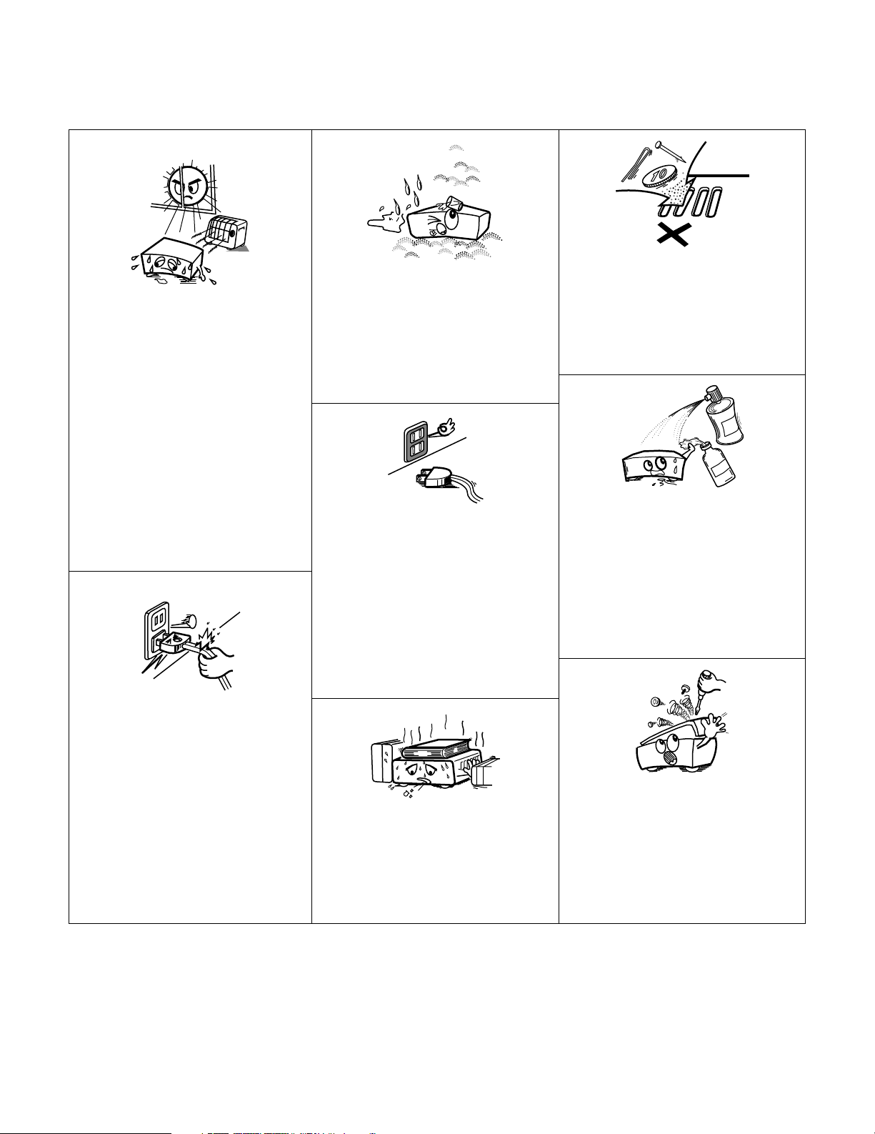
•Avoid high temperatures.
Allow for sufficient heat dispersion when installed
on a rack.
•Vermeiden Sie hohe Temperaturen.
Beachten Sie, daß eine ausreichend Luftzirkulation
gewährleistet wird, wenn das Gerät auf ein Regal
gestellt wird.
• Eviter des températures élevées
Tenir compte d’une dispersion de chaleur suffisante
lors de l’installation sur une étagère.
• Evitate di esporre l’unità a temperature alte.
Assicuratevi che ci sia un’adeguata dispersione del
calore quando installate l’unità in un mobile per
componenti audio.
• Evite altas temperaturas
Permite la suficiente dispersión del calor cuando
está instalado en la consola.
•Vermijd hoge temperaturen.
Zorg voor een degelijk hitteafvoer indien het
apparaat op een rek wordt geplaatst.
• Undvik höga temperaturer.
Se till att det finns möjlighet till god värmeavledning
vid montering i ett rack.
• Handle the power cord carefully.
Hold the plug when unplugging the cord.
• Gehen Sie vorsichtig mit dem Netzkabel um.
Halten Sie das Kabel am Stecker, wenn Sie den
Stecker herausziehen.
• Manipuler le cordon d’alimentation avec précaution.
Tenir la prise lors du débranchement du cordon.
• Manneggiate il filo di alimentazione con cura.
Agite per la spina quando scollegate il cavo dalla
presa.
• Maneje el cordón de energía con cuidado.
Sostenga el enchufe cuando desconecte el cordón
de energía.
• Hanteer het netsnoer voorzichtig.
Houd het snoer bij de stekker vast wanneer deze
moet worden aan- of losgekoppeld.
• Hantera nätkabeln varsamt.
Håll i kabeln när den kopplas från el-uttaget.
• Keep the set free from moisture, water, and dust.
• Halten Sie das Gerät von Feuchtigkeit, Wasser und
Staub fern.
•Protéger l’appareil contre l’humidité, l’eau et
lapoussière.
•Tenete l’unità lontana dall’umidità, dall’acqua e dalla
polvere.
• Mantenga el equipo libre de humedad, agua y polvo.
• Laat geen vochtigheid, water of stof in het apparaat
binnendringen.
• Utsätt inte apparaten för fukt, vatten och damm.
• Unplug the power cord when not using the set for
long periods of time.
•Wenn das Gerät eine längere Zeit nicht verwendet
werden soll, trennen Sie das Netzkabel vom Netzstecker.
• Débrancher le cordon d’alimentation lorsque l’appareil
n’est pas utilisé pendant de longues périodes.
• Disinnestate il filo di alimentazione quando avete
l’intenzione di non usare il filo di alimentazione per un
lungo periodo di tempo.
• Desconecte el cordón de energía cuando no utilice el
equipo por mucho tiempo.
• Neem altijd het netsnoer uit het stopkontakt wanneer
het apparaat gedurende een lange periode niet wordt
gebruikt.
• Koppla ur nätkabeln om apparaten inte kommer att
användas i lång tid.
* (For sets with ventilation holes)
• Do not obstruct the ventilation holes.
• Die Belüftungsöffnungen dürfen nicht verdeckt
werden.
• Ne pas obstruer les trous d’aération.
• Non coprite i fori di ventilazione.
• No obstruya los orificios de ventilación.
• De ventilatieopeningen mogen niet worden beblokkeerd.
• Täpp inte till ventilationsöppningarna.
• Do not let foreign objects in the set.
• Keine fremden Gegenstände in das Gerät kommen
lassen.
• Ne pas laisser des objets étrangers dans l’appareil.
• E’ importante che nessun oggetto è inserito
all’interno dell’unità.
• No deje objetos extraños dentro del equipo.
• Laat geen vreemde voorwerpen in dit apparaat vallen.
• Se till att främmande föremål inte tränger in i
apparaten.
• Do not let insecticides, benzene, and thinner come in
contact with the set.
• Lassen Sie das Gerät nicht mit Insektiziden, Benzin
oder Verdünnungsmitteln in Berührung kommen.
• Ne pas mettre en contact des insecticides, du
benzène et un diluant avec l’appareil.
• Assicuratevvi che l’unità non venga in contatto con
insetticidi, benzolo o solventi.
• No permita el contacto de insecticidas, gasolina y
diluyentes con el equipo.
• Laat geen insektenverdelgende middelen, benzine of
verfverdunner met dit apparaat in kontakt komen.
• Se till att inte insektsmedel på spraybruk, bensen och
thinner kommer i kontakt med apparatens hölje.
• Never disassemble or modify the set in any way.
•Versuchen Sie niemals das Gerät auseinander zu
nehmen oder auf jegliche Art zu verändern.
• Ne jamais démonter ou modifier l’appareil d’une
manière ou d’une autre.
• Non smontate mai, nè modificate l’unità in nessun
modo.
• Nunca desarme o modifique el equipo de ninguna
manera.
• Nooit dit apparaat demonteren of op andere wijze
modifiëren.
•Ta inte isär apparaten och försök inte bygga om den.
Page 4

4
2 INTRODUCTION
Thank you for choosing the DENON AVC-A1XV Digital Surround A / V amplifier. This remarkable component has been engineered to provide superb
surround sound listening with home theater sources such as DVD, as well as providing outstanding high fidelity reproduction of your favorite music
sources.
As this product is provided with an immense array of features, we recommend that before you begin hookup and operation that you review the
contents of this manual before proceeding.
TABLE OF CONTENTS
z
Before Using...............................................................................6
x
Cautions on Installation............................................................6
c
Cautions on Handling................................................................7
v
Features..................................................................................7~9
b
Connections ...............................................................................9
Connecting Audio Components.................................................10
Connecting Video Components.................................................11
Connecting video components equipped with S-Video
jacks...........................................................................................12
Connecting video components equipped with Component
Video video jacks .......................................................................13
Video Conversion Function..................................................13, 14
Connecting equipment with HDMI terminals............................14
Connecting equipment with DVI terminals ...............................15
Connecting the external input (EXT.IN) jacks ............................16
Connecting the ZONE2 jacks.....................................................17
Connecting a component with video and audio jacks to
the V.AUX input jacks ................................................................17
DENON LINK connections.........................................................18
Connecting IEEE1394 devices...................................................19
Speaker system connections ..............................................20, 21
n
Part Names and Functions
Front panel...........................................................................22, 23
Display .......................................................................................24
Remote control unit...................................................................25
m
System Setup...........................................................................26
System setup items and default values..............................26~28
Speaker system layout ..............................................................29
Before setting up the system....................................................30
Auto Setup / Room EQ..............................................................30
Measurement flow ...............................................................31
Before performing the Auto Setup procedure .....................32
(I) Connecting the microphone for Auto Setup ........................32
[1] Auto Setup / Room EQ......................................................33
1-1. Setting the Auto Setup.........................................................33
(II) Extra Setup ...........................................................................34
(
III
)Preliminary measurements...................................................35
(IV) Speaker System measurement......................................36, 37
(V) Check of the measurement result .................................38, 39
About the error message .....................................................39
1-2. Setting the Room EQ Setup...........................................40, 41
1-3. Setting the Direct Mode.......................................................41
1-4. Setting the MIC Input Select................................................42
1-5. Check the Parameter .....................................................43~45
[2] Speaker Setup ....................................................................45
2-1. Setting the type of speakers..........................................46, 47
2-2. Setting the low frequency distribution...........................47, 48
2-3. Setting the Delay Time ...................................................48, 49
2-4. Setting the Channel Level..............................................50, 51
2-5. Setting the Crossover Frequency.........................................52
Setting the crossover frequency individually
for the different channels...............................................53
2-6. Selecting the Surround Speakers for the
different surround modes.....................................................54
2-7. Setting the THX Audio Setup
[1] Setting for using a THX Ultra2 compatible
subwoofer ......................................................................55
[2] Surround Back Speaker Position Settings......................56
[3] Audio Input Setup ..............................................................57
3-1. Setting the Digital In Assignment ..................................57, 58
3-2. Setting the EXT.IN Setup................................................59, 60
3-3. Setting the Input Function Level ..........................................61
3-4. Setting the Function Rename ........................................62, 63
3-5. Setting the IEEE1394 Assign ...............................................64
3-6. Selecting the IEEE1394 Auto Function ................................65
[4] Video Setup ........................................................................66
4-1. Setting the Component In Assign..................................66, 67
4-2. Setting the Video Convert Mode....................................67, 68
4-3. Setting the Video Scaler.................................................68, 69
4-4. Setting the 3D Y/C Separation..............................................69
4-5. Setting the HDMI/DVI In Assign ....................................70, 71
4-6. Setting the Audio Delay..................................................71, 72
4-7. Setting the On Screen Display (OSD) ............................72, 73
[5] Advanced Playback ............................................................73
5-1. Setting the 2ch Direct/Stereo...............................................74
Setting the front B speakers when the surround
mode is set to the 2-channel Direct or Stereo...............74
5-2. Setting the Dolby Digital Setup ............................................75
5-3. Setting Auto Surround Mode ...............................................76
5-4. Setting the Manual EQ Setup ........................................77, 78
Procedure for copying the “Flat” correction curve........79
[6] Zone Setup (ZONE2 = 5.1/7.1ch) ......................................80
6-1. Setting the type of speakers for ZONE2..............................81
6-2. Setting the low frequency distribution for ZONE2...............82
6-3. Setting the Delay Time for ZONE2.................................83, 84
6-4. Setting the Channel Level for ZONE2...........................85, 86
6-5. Setting the Crossover Frequency for ZONE2.......................87
6-6. Setting the Video Setup for ZONE2
[1] Video Convert Mode ................................................88, 89
[2] Audio Delay ....................................................................89
6-7. ZONE3 and ZONE4 tone control and channel level
setting.............................................................................90, 91
Zone Setup setting when ZONE2 is set to STEREO or
MONO..........................................................................................91
[7] Option Setup.......................................................................92
7-1. Setting the Channel Setup ...................................................92
Channel setup flow ..................................................92, 93
The number of channels that can be selected ..............94
The subwoofer output composition...............................94
Connecting the preouts..................................................95
7-2. Setting the Power Amplifier Assignment.............................96
Power amplifier assignment flow ............................96, 97
Amp Assign mode..........................................................98
Bi-Amp connection.........................................................98
Table of power amplifier assignment modes ........98~100
Table of channels to which power amplifiers can
be assigned ..................................................................100
7-3. Setting the Volume Control........................................101, 102
7-4. Setting the Trigger Out ...............................................102, 103
7-5. Setting the AC Outlet Assign .............................................104
7-6. Protecting the setting and memory backup
[1] User Memory .......................................................105, 106
[2] Setup Lock ...........................................................106, 107
After Completing system setup.................................................107
Page 5

5
,
Remote Control Unit
Inserting the Batteries .............................................................108
Using the Remote Control Unit ...............................................108
Operating DENON audio components ............................109, 110
Preset memory........................................................................111
Operating a component stored in the preset memory ...112, 113
Learning function.....................................................................114
System call ......................................................................115, 116
Punch Through ........................................................................116
Setting the back light’s lighting time.......................................117
Setting the brightness .............................................................117
Resetting .........................................................................118, 119
.
Operation
Operating the Remote control unit..........................................120
Before operating......................................................................120
Playing the input source..................................................121, 122
Playback using external input (EXT.IN) jacks ...........................123
Playing audio sources (CDs and DVDs)...................................124
After stating playback
[1] Setting the Room EQ...................................................125
[2] Listening over headphone............................................125
[3] Turning the sound off temporarily (MUTING)...............125
[4] Combining the currently playing sound with
the desired image (VIDEO SELECT) ............................125
[5] Checking the currently playing program source, etc. ..126
[6] Switching the surround speakers ................................126
[7] Switching between HDMI and DVI monitor output.....126
[8] Selection of resolution setting (SCALE) .......................127
Multi-source recording/playback
[1] Playing one source while recording another
(REC OUT mode)..........................................................127
[2] Recording Dolby Digital and DTS multichannel
sources.........................................................................128
[3] Dolby Headphone recording.........................................128
⁄0
Surround
Adjustment steps that need to be performed prior to
surround sound playback
[1] Test Tone ......................................................................129
[2] Channel Level.......................................................129, 130
Fader function..........................................................................130
Playing modes for different sources .......................................131
THX Surround EX / Home THX Cinema mode
[1] Playing sources recorded in Dolby Surround in the
Home THX Cinema surround mode.....................132, 133
[2] To play in the THX Surround EX/Home THX Cinema
Surround mode for sources recorded in Dolby Digital
or DTS ..........................................................................134
Dolby Digital mode and DTS Surround............................135, 136
Dolby Pro Logic IIx (Dolby Pro Logic II) mode................137, 138
DTS NEO:6 mode............................................................139, 140
The Dolby Headphone.....................................................140, 141
Memory and call-out functions (USER MODE function) .........141
⁄1
DENON Original Surround Modes
Surround modes and their features.........................................142
DSP surround simulation.................................................143, 144
Tone control setting
[1] Adjusting the tone using the Remote control
unit .......................................................................144, 145
[2] Adjusting the tone from the Main unit.........................145
⁄2
Multi Zone
Multi-zone playback with multi-source ....................................146
[1] ZONE2 playback ..................................................147~149
[2] ZONE3 playback...........................................................150
[3] ZONE4 playback...........................................................151
[4] Outputting a program source to amplifier, etc., in a
ZONE2 room (ZONE2 SELECT mode) .........................152
[5] Outputting a program source to amplifier, etc., in a
ZONE3 or ZONE4 room
(ZONE3, ZONE4 SELECT mode)..................................152
Remote control unit operations during multi-source
playback ...................................................................................153
System Setup for multi-zone...................................................154
Adjustment steps that need to be performed prior to
surround sound playback in ZONE2
[1] Test Tone ......................................................................154
[2] Channel Level...............................................................155
Fader function..........................................................................156
ZONE2 Surround......................................................................157
Memory and call-out functions of ZONE2
(USER MODE function) ...........................................................158
ZONE2 tone control setting.............................................159, 160
⁄3
Last Function Memory..........................................................160
⁄4
Initialization of the Microprocessor.....................................160
⁄5
Troubleshooting.....................................................................161
⁄6
Additional Information
Optimum surround sound for different sources......................162
Surround back speakers ..........................................................163
Speaker setting examples
[1] For THX Surround EX systems
(using surround back speakers) ...........................164, 165
[2] When not using surround back speakers ....................165
Surround
[1] Dolby Surround ....................................................166, 167
[2] DTS Digital Surround............................................167, 168
[3] DTS-ES Extended Surround™......................................168
[4] DTS 96/24 ....................................................................169
[5] Home THX Cinema Surround...............................169, 170
[6] THX Surround EX .........................................................170
Audyssey MultEQ XT ..............................................................171
HDCD.......................................................................................171
DENON LINK ...........................................................................172
About IEEE1394 ......................................................................172
About HDMI.............................................................................172
Advanced AL24 Processing.....................................................172
Surround modes and parameters....................................173, 174
Relationship between the video input signal and
monitor output (MAIN ZONE)..................................................175
Relationship between the video input signal and
monitor output (ZONE2) ..........................................................176
⁄7
Specifications.........................................................................177
Page 6
6
1
BEFORE USING
2
CAUTIONS ON INSTALLATION
Pay attention to the following before using this unit:
• Moving the set
To prevent short circuits or damaged wires in the connection cords,
always unplug the power cord and disconnect the connection
cords between all other audio components when moving the set.
• Before turning the power switch on
Check once again that all connections are proper and that there are
not problems with the connection cords. Always set the power
switch to the standby position before connecting and disconnecting
connection cords.
• Store these instructions in a safe place.
After reading, store these instructions along with the warranty in a
safe place.
• Note that the illustrations in these instructions may differ
from the actual set for explanation purposes.
Noise or disturbance of the picture may be generated if this unit or
any other electronic equipment using microprocessors is used near a
tuner or TV.
If this happens, take the following steps:
• Install this unit as far as possible from the tuner or TV.
• Set the antenna wires from the tuner or TV away from this unit’s
power cord and input/output connection cords.
• Noise or disturbance tends to occur particularly when using indoor
antennas or 300 Ω/ohms feeder wires. We recommend using
outdoor antennas and 75 Ω/ohms coaxial cables.
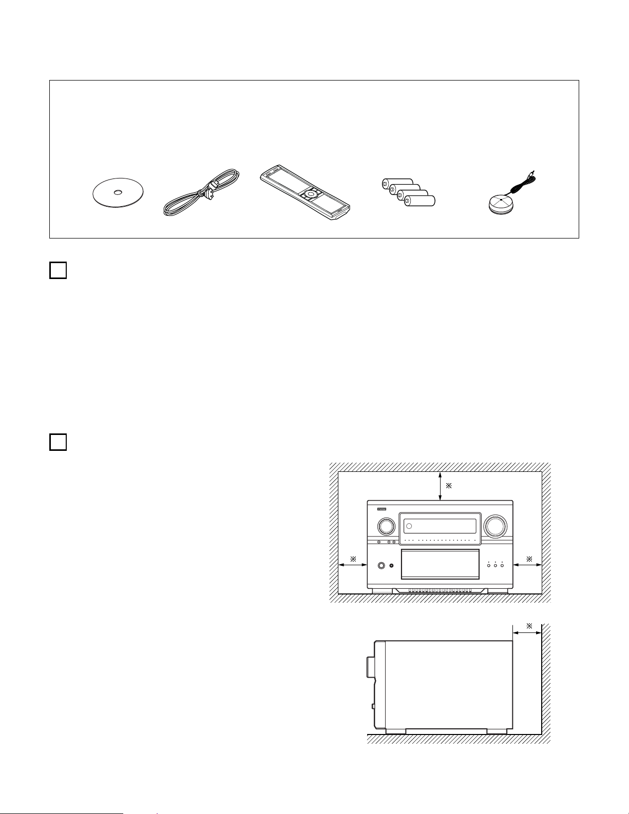
Note:
For heat dispersal, do not install this equipment in a confined
space such as a book case or similar unit.
Wall
Note
2 ACCESSORIES
Check that the following parts are included in addition to the main unit:
q Operating instructions ..............................................................1
w CD-ROM (Operating instructions) ............................................1
e Service station list ....................................................................1
r AC cord.....................................................................................1
rw
t
yu
t Remote control unit (RC-995)...................................................1
y R03/AAA alkaline batteries .......................................................4
u Omnidirectional microphone ....................................................1
i List of preset codes..................................................................1
Page 7

7
4
FEATURES
1. DENON Proprietary Digital Technology
1) NEW D.D.S.C.-Digital (Dynamic Discrete Surround Circuit)
Powered by four high performance, high speed 32 bit floating
point DSP processors, the AVC-A1XV represents the pinnacle
of precision DSP processing technology. Unlike competitive
units, DENON’s discrete surround technology consists of
selected individual processors and ancillary elements, working
in harmony via proprietary DENON inter-IC digital communication
technology.
2) DENON Link
With select DENON DVD players that feature DENON Link
digital outputs, encrypted digital multi-channel audio transfers
to the AVC-A1XV directly, eliminating unnecessary digital-toanalog and subsequent analog-to-digital conversions for the
highest possible signal transfer integrity. The DENON Link
function supports up to ultra high resolution 192 kHz DVD-A
digital datastreams, for maximum reproduced fidelity.
3) Latest AL24 DSP Processing
DENON’s acclaimed Advanced AL24 DSP processing improves
the fidelity of high resolution stereo PCM sources such as CD
and DVD (up to 192 kHz sampling frequencies), by
sophisticated DSP processing algorithms that improve low
level detail and enhance fidelity by upsampling and adaptive
filtering techniques. Advanced AL24 provides increased
dynamic range and spatial information; bring out all the
nuances with optimum clarity and natural fidelity.
4) AL24 DSP Processing For All Channels
For the AVC-A1XV, DENON’s AL24 processing supports multichannel DVD-Audio for all channels, including the ZONE2 multichannel theater channels, for optimum fidelity and low level
detail reproduction in both the MAIN ZONE as well as the
second multi-channel ZONE2 system.
2. Latest Surround Decoding Technology
1) Dolby Digital
Using advanced digital audio compression and decoding
technologies, Dolby Digital provides up to 5.1 channels of wide
bandwidth, wide dynamic range multi-channel high fidelity
surround sound. Dolby Digital is the default digital multichannel audio delivery system for DVD and USA/Canada high
definition television systems.
2) Dolby Pro Logic IIx
Dolby Pro Logic
IIx adds the ability to provide up to 7.1 channel
reproduction from conventional stereo (2 channel) sources,
including surround back reproduction with a 6.1 or 7.1 surround
sound system. Pro Logic IIx has three modes: one for moviebased soundtracks; one for stereo music sources, and a game
mode for game consoles with stereo (2 channel) audio outputs.
3) Dolby Headphone
Developed jointly by Dolby Laboratories and Lake Technology
Ltd. of Australia, Dolby Headphone decoding provides thrilling
surround sound effects of your favorite movie and music
sources when using conventional stereo headphones.
4) DTS (Digital Theater Systems)
DTS provides up to 5.1 channels of wide-range, high fidelity
surround sound from sources such as DTS-encoded CDs,
DVDs with DTS soundtracks, and DVD-Audio discs that provide
DTS soundtracks.
5) DTS-ES Extended Surround and DTS Neo:6
The AVC-A1XV also supports the DTS-ES 6.1 matrix and
discrete encoded surround formats, and also features DTS
Neo:6 stereo-to-surround decoding with both Music and Movie
modes for superb surround sound from conventional stereo
sources.
6) DTS 96/24 Decoding
Digital Theater Systems 96/24 provides ultra high resolution 24
bit, 96 kHz sampling for optimum wide bandwidth fidelity and
superb dynamic range. The AVC-A1XV is equipped to faithfully
decode DTS 96/24 discs.
7) HDCD High Definition Compatible Digital
Using sophisticated encoding and decoding technologies, the
HDCD format provides improved fidelity and dynamic range
from encoded Compact Discs (which number in the thousands
of titles). The AVC-A1XV, via a standard digital audio connection
from a CD player or DVD player, internally recognizes and
decodes HDCD discs for optimum fidelity and widest dynamic
range.
8) Home THX Ultra2 Certified
Home THX is the unique collaboration between THX Ltd. and
audio/video equipment manufacturers. THX Ultra2 certification
is the highest performance level, and provides a rigorous set of
performance standards along with proprietary surround sound
post-processing technologies, all designed to maximize the
surround soundtrack playback experience in the home theater.
In addition, the AVC-A1XV is fully compatible with THX
Surround EX, which provides extended surround sound via
additional surround back channel reproduction, first employed
on Star Wars Episode 1 – The Phantom Menace, and featured
on many major motion pictures since. As well, the AVC-A1XV’s
power amplifier section fully complies with the latest THX
Ultra2 standards, and two new addition surround modes are
also provided – THX Ultra2 Cinema mode and THX Music
mode. In addition, the AVC-A1XV also incorporates THX’s new
THX Games mode, for thrilling surround sound effects from
two channel game box audio sources.
3
CAUTIONS ON HANDLING
• Switching the input function when input jacks are not
connected
A clicking noise may be produced if the input function is switched
when nothing is connected to the input jacks. If this happens,
either turn down the MASTER VOLUME control or connect
components to the input jacks.
• Muting of PRE OUT jacks and SPEAKER terminals
The PRE OUT jacks and SPEAKER terminals include a muting
circuit. Because of this, the output signals are greatly reduced for
several seconds after the power switch is turned on or input
function, surround mode or any other-set-up is changed. If the
volume is turned up during this time, the output will be very high
after the muting circuit stops functioning. Always wait until the
muting circuit turns off before adjusting the volume.
• Whenever the power switch is in the STANDBY state, the
apparatus is still connected on AC line voltage.
Please be sure to turn off the power switch or unplug the cord
when you leave home for, say, a vacation.
Page 8

8
3. Movie & Music Surround For The Whole House
The AVC-A1XV’s versatile Multi Source functions let you select
different audio and video sources for each room in your home.
Different audio and video multi-channel sources can be enjoyed in
the home theater (Main room), as well as a multi-channel audio
and video source directed to a second room. Additional zones (3
and 4) can also receive video and stereo audio as well. The AVCA1XV features Freely Assignable Ten Power Amp Channels, so
that you can decide which power amp channels can be dedicated
to the MAIN ZONE, the secondary zone (ZONE2) as well as to two
additional zones (ZONE3 and ZONE4), as well as providing line
level outputs to external power amplifiers.
1) ZONE2 Theater Capability
With up to 9.1 system in the main home theater room, the
AVC-A1XV provides for a second, fully 5.1 capable system in
ZONE2, with component video and five amplifier channels as
well, with video up-conversion if desired.
2) ZONE3 Independent Audio & Video
The AVC-A1XV provides the ability for a third independent
zone, with selectable audio and video sources.
3) ZONE4 Independent Audio
ZONE4 is ideal for a room where you can enjoy a different
stereo source, for background music listening.
4. Ten High Power Assignable Power Amplifiers
1) Featuring high current, THX-certified high power amplifier
channels, the AVC-A1XV is equipped to drive high performance
loudspeakers with unprecedented dynamic range and low
impedance drive capability, with each of the ten amplifier
channels rated at 170 W into 8 Ω/ohms. Each channel can be
freely assigned to the main home theater room, as well as
assigned to additional zones for multi-channel or stereo or even
monophonic distributed audio/video and audio-only functions.
For example, you might choose to have seven amplifier
channels dedicated to a full THX Surround EX & DTS Surround
EX 7.1 channel system in the main room, while still allowing a
powered stereo function in the second zone, and a third
monophonic background music function in another room. Or,
you could have a principal 5.1 channel setup in the main home
theater room, while having a secondary powered 5.1 system in
the second zone. You could even have (with compatible biamplified-capable speakers) a true 5.1 bi-amped system in the
main room, along with additional line-level-powered systems in
up to three additional rooms.
5. Audiophile Audio Quality Throughout
1) Separated Pure Audio & Video Chassis Construction
For optimum audio and video quality, the AVC-A1XV features
dedicated and physically separated low and high level audio
and video circuits to prevent degrading mutual interference.
2) Optimum Chassis Stability
As the AVC-A1XV is equipped with a massive toroidal main
power supply and additional secondary power supplies,
centrally located within the chassis, a fifth chassis foot helps
reduce the physical vibration that can cause mechanicallyinduced vibration-related distortions.
3) Multiple Separate Power Supply Topologies
No less than six individual power transformers (one very large
toroidal unit, and five additional lower voltage power
transformer units) are provided, ensuring that each critical subsection draws power from its own dedicated supply,
eliminating minute fluctuations that occur with single
transformer-equipped competitive units.
4) Multiple Toroidal Sub-Windings
The massive main toroidal power transformer (which powers
the ten amplifier channels block) features dedicated subwindings and high current, ultra stable DC rectifiers and high
rated smoothing/storage capacitors, with a tremendous
132,000 µF total storage capacity.
5) Pure Direct Mode
According to the selected input source, the Pure Direct Mode
provides the optimum decoding by switching off any and all
unnecessary processing (video disable, tone bybass, and other
unnecessary circuits).
6) Dual Surround Speaker Mode
DENON was the first to introduce Dual Surround Mode
Speaker Switching, where two different types (and positions)
of surround speakers could be chosen according to the source
material – diffuse surround speakers located at the sides of the
listening position for movie surround sound, and directional
surround speakers located at the room’s rear corners for music
surround sound. The AVC-A1XV also adds the ability to have
both powered (AVC-A1XV amplified) music and surround
sound speaker systems, according to each individual home
theater’s setup circumstances.
7) Highest Quality Input & Output Terminals
The AVC-A1XV audio and video input terminals are gold-plated,
as are the ten speaker terminal pairs.
6. High Resolution Video Section
1) Component Video Switching
In addition to composite and S-video switching, the AVC-A1XV
provides no less than five sets of component video inputs via
RCA-type coaxial connectors, as well as an additional sixth set
of component video inputs via BNC connectors, as well as two
sets of component video outputs (one for RCA-type coaxial,
one for BNC connectors), with additional capability for
component video output to ZONE2. These component video
circuits are fully HD-compatible, with a flat response to 100
MHz, far above the 38 MHz requirement for true HD
reproduction, ensuring crisp and clear HDTV picture quality.
2) Video Up And Down Conversion Function
To eliminate video signal incompatibility, the AVC-A1XV is
equipped with video up-conversion and down-conversion.
Composite and S-video signals are internally up-converted to
component video for the MAIN ZONE, and down-converted for
480i component video signals. ZONE2 features downconversion from S-video to composite video.
3) Progressive Scanning & Scaling Function
Via high quality Faroudja DCDi™ (*1) processing, the AVCA1XV converts standard definition interlaced video to higher
resolution progressive scanning format – 480i interlace to 480p
progressive. For non-copy-protected video signals, further upconversion to HD 1080i video is also provided, for highest
visual quality with compatible HD video displays.
4) High Resolution 12 bit/216 MHz Video D/A Conversion
Featuring Analog Devices ADV-7310 Noise Shaped Video (*2)
digital-to-analog converters, the AVC-A1XV provides superior
high resolution video output free from video noise and
conversion artifacts.
5) Superior S-video Processing
A 3-dimensional Y-C separation circuit provides artifact-free
composite video to S-video up-conversion, and Time Base
Correction for optimum color sharpness with composite video
inputs (MAIN ZONE).
7. Latest Digital A/V Input/Output Capability With Future Upgrade
Ability
1) HDMI/DVI Switching
High Definition Multi-media Interface provides digital audio and
video signal transfer between source components, the AVCA1XV, and compatible video displays with HDMI digital
interface. Digital Visual Interface provides similar digital
input/output capability for digital video signals. The AVC-A1XV
is equipped with three HDMI inputs and one DVI input, and
one each HDMI and DVI outputs to compatible video displays.
Each HDMI/DVI input feeds both HDMI and DVI outputs, for
optimum compatibility with today’s HDMI- and DVI-equipped
video displays.
Page 9

9
5
CONNECTIONS
• Do not plug in the AC cord until all connections have been
completed.
• Be sure to connect the left and right channels properly (left with
left, right with right).
• Insert the plugs securely. Incomplete connections will result in
the generation of noise.
• Use the AC OUTLET for audio equipment only. Do not use
them for hair driers, etc.
• Note that binding pin plug cords together with AC cords or
placing them near a power transformer will result in generating
hum or other noise.
• Noise or humming may be generated if a connected audio
equipment is used independently without turning the power of
this unit on. If this happens, turn on the power of the this unit
.
2) IEEE 1394 Compatability
Two IEEE 1394 digital interface inputs are provided, allowing
SACD DSD and DVD-Audio digital audio signal input capability
with select DENON DVD players that feature IEEE 1394 digital
output function, and feature DENON’s D.A.S.S. (DENON Audio
Synchronized System) function, which reduces data jitter for
superior high resolution DSD and PCM reproduction.
3) Ethernet Function
For full compatibility with external control systems, such as
AMX and Crestron, the AVC-A1XV features Ethernet
connectivity.
4) RS-232C Serial Input/Output Function
For full compatibility with external control systems, such as
AMX and Crestron, the AVC-A1XV features a RS-232C serial
I/O port. A second RS-232C serial I/O port is provided on the
front panel, for future software and system upgrade capability.
5) Future Surround Format Inputs & Outputs
For possible future surround sound formats, the AVC-A1XV
features up to ten channel audio inputs (nine main channels
plus an additional low frequency effects channel), with high
resolution A/D conversion on each input. A second set of 5.1
analog inputs is also provided, for connection to surround
sources such as SACD and/or DVD-Audio players.
8. Easy-To-Use Functions
1) Automatic Setup With Room Equalization
Featuring the newest Audyssey MultEQ XT technology, the
AVC-A1XV provides automatic room equalization with multiple
measurement points for optimum response throughout the
listening room. A high quality measuring microphone (DENON
DMS-305) is provided.
2) Three User-Definable Easy Modes
Three User Modes are provided, allowing you to store and
recall your favorite surround modes with individual level
memories at the touch of a button.
3) Digital Audio Delay Function
For optimum picture and sound synchronization, the AVC-A1XV
features an adjustable digital audio delay function, variable
from 0 ~ 200 milli-seconds.
4) Adjustable Crossover Frequencies
For the widest compatibility with various main speaker and
subwoofer combinations, the AVC-A1XV is equipped with a
choice of ten different crossover frequencies (40, 60, 80, 90,
100, 110, 120, 150, 200 and 250 Hz crossover points),
individually adjustable for each of the main speaker systems.
5) The AVC-A1XV provides dual subwoofer outputs, along with an
additional subwoofer output dedicated for the Low Frequency
Effects channel (MAIN ZONE).
6) Auto Surround Mode
For each input source, a separate memory stores your
preferred surround sound mode and other settings, eliminating
the need to re-configure the surround mode parameters
whenever you switch between input sources.
7) Assignable High Current Trigger Outputs
Four different 12 Volt trigger outputs allow the automatic
activation of externally controlled devices, such as motorized
drop-down screens, motorized drapery, motorized screen
masking systems and other trigger-activated systems. Each
port supports 12V/250mA trigger-activated functions,
assignable by zone (MAIN ZONE, ZONE2, ZONE3, or ZONE4).
8) Assignable AC Outlet
Assignable AC convenience outlet is provided, and it can be
activated by choice of input source or surround sound mode by
each zone, to activate specific external components as
necessary.
9) Front Panel Convenience Inputs
A set of front panel A/V inputs allows quick connection of A/V
sources, such as a video camcorder or a game console.
10) Electro-Luminescent Membrane Touch-Panel Remote Control
Featuring back-lit EL technology, the AVC-A1XV remote control
displays a specific function key set for each selected
component, and is pre-programmed with hundreds of remote
control code sets and features learning capability as well.
11) Large Fluorescent Display
For easy setup and system monitoring, the AVC-A1XV features
a clearly readable FL display that provides extensive system
status and setup monitoring.
12) AC Input
Detachable AC Cord.
13) Other Useful Functions
Digital Audio Input to Analog Recording Output conversion
Input Source Re-naming Function
Audio Level Memories for each input
Personal Memory Plus function stores surround mode, level
memories, analog or digital input selection for each input
Volume Level Limiter provides a user-definable pre-set volume
level for multi-zone audio operation
Power On Volume Level Memory provides a user-definable
volume level that is activated every time the AVC-A1XV is
powered up
Setup Lock Function prevents mis-operation at start-up
Personal Default Memory function
*1: “DCDi™” is trademark of Faroodja, a division of Genesis
Microchip Inc.
*2: “NSV” is a trademark of Analog Devices, Inc.
Page 10
10
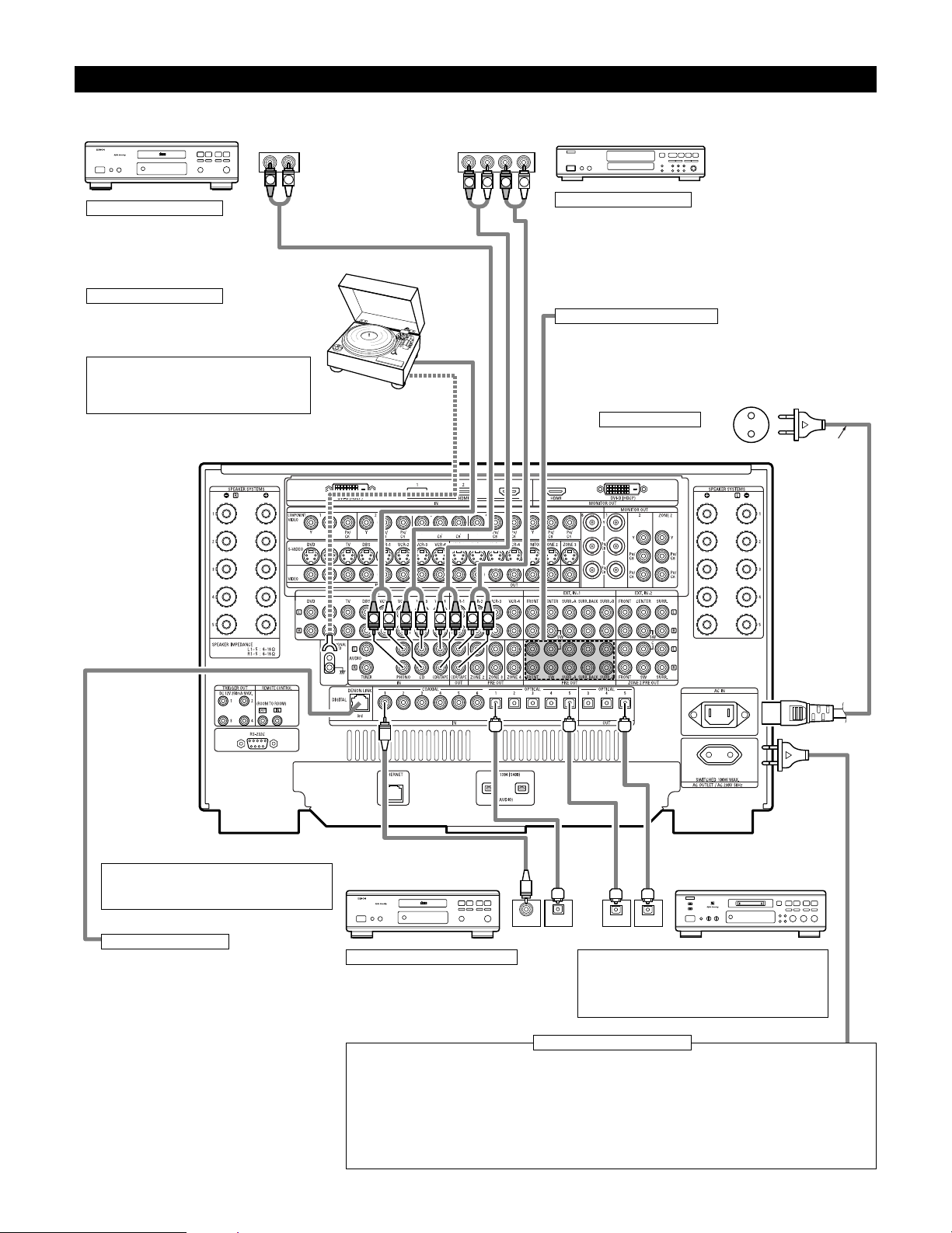
Connecting Audio Components
• When making connections, also refer to the operating instructions of the other components.
OUTPUT INPUT
OPTICAL
RLRL
OUTPUT INPUT
R
OUTPUT
L
OPTICALCOAXIAL
OUTPUT
RLR
L
R L R L
R
L
R
L
R
L
B
DIGITAL AUDIO
B
DIGITAL AUDIO
CD player
Connecting a CD player
Connect the CD player’s analog output
jacks (ANALOG OUTPUT) to this unit’s CD
jacks using pin plug cords.
Connecting a turntable
Connect the turntable’s output cord to the AVCA1XV’s PHONO jacks, the L (left) plug to the L jack,
the R (right) plug to the right jack.
NOTE:
This unit cannot be used with MC cartridges
directly. Use a separate head amplifier or step-up
transformer.
If humming or other noise is generated when the ground wire is connected,
disconnect the ground wire.
Turntable
(MM cartridge)
Ground wire
AC cord
(Supplied)
Connecting the pre-out jacks
Use these jacks if you wish to connect external power amplifier(s) to increase
the power of the front, center, surround and surround back sound channels,
or for connection to powered loudspeakers.
When using only one surround back speaker, connect it to left channel.
Connecting the AC OUTLET
AC OUTLET
• SWITCHED (total capacity – 100 W)
The power to the outlet is turned on and off in conjunction with the POWER switch on the main unit, and when the power
is switched between on and standby from the remote control unit.
No power is supplied from this outlet when this unit’s power is at standby. Never connect equipment whose total capacity
is above 100 W.
NOTES:
• Only use the AC OUTLET for audio equipment. Never use them for hair driers, TVs or other electrical appliances.
• The AC outlet can be set to turn on and off for the different functions.
For details, see “Setting the AC Outlet Assign”. (See page 104)
AC outlets (wall)
AC 230V, 50Hz
MD recorder, CD recorder or other
component equipped with digital
input/output jacks
CD player or other component
equipped with digital output jacks
Connecting the DIGITAL jacks
Use these for connections to audio equipment with
digital output. Only one type of connector needs to
be used, you can decide which based on availability
of coaxial and optical inputs. Refer to pages 57, 58
for instructions on setting this terminal.
NOTES:
• Use 75 Ω/ohms cable pin cords for coaxial connections.
• Use optical cables for optical connections, removing the
cap before connecting.
Connecting a tape deck
Connections for recording:
Connect the tape deck’s recording input jacks (LINE IN or REC) to this unit’s
tape recording (OUT) jacks using pin plug cords.
Connections for playback:
Connect the tape deck’s playback output jacks (LINE OUT or PB) to this unit’s
tape playback (IN) jacks using pin plug cords.
CD recorder or Tape deck
DENON Link terminal
Use this terminal to connect a DENON DVD player for
high quality digital multichannel sound.
(See page 18)
Route the connection cords, etc., in such a way that
they do not obstruct the ventilation holes.
Page 11
11
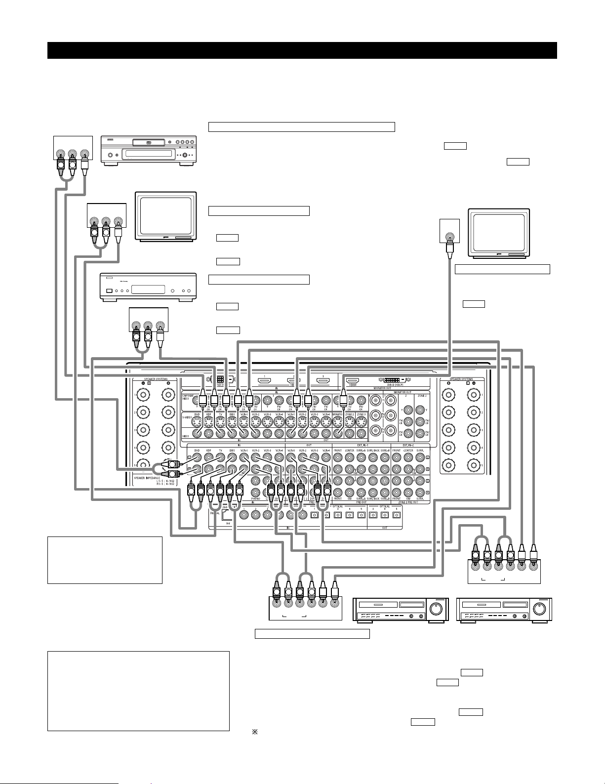
Connecting Video Components
•To connect the video signal, connect using a 75 Ω/ohms video signal cable cord. Using an improper cable can result in a drop in picture quality.
• When making connections, also refer to the operating instructions of the other components.
• The AVC-A1XV is equipped with a function for up and down converting video signals. (See page 13)
The signal connected to the video signal terminal is output to the S-Video and component video monitor out terminals.
But the REC OUT terminals have no conversion function, so when recording connect the appropriate video terminals.
R OUT
VIDEO
OUT
L
AUDIO
R OUT
VIDEO
OUT
L
AUDIO
R OUT IN
AUDIO
VIDEO
OUT IN
LRL
R OUT IN
AUDIO
VIDEO
OUT IN
LRL
R OUT
VIDEO
OUT
L
AUDIO
IN
VIDEO
R
L
R
L
RLR
L
R
L
R
L
R
L
R
L
R
L
R
L
R
L
R
L
R
L
R
L
B
TV
DVD player or video disc player (VDP), etc.
Monitor TV
Connecting a TV tuner
TV
• Connect the TV’s tuner’s video output jack (VIDEO OUTPUT) to the
(yellow) TV IN jack using a 75 Ω/ohms video coaxial pin plug
cord.
• Connect the TV’s tuner’s audio output jacks (AUDIO OUTPUT) to the
TV IN jacks using pin plug cords.
AUDIO
VIDEO
C
onnecting a DVD player or a video disc player (VDP)
DVD
• Connect the video disc player’s video output jack (VIDEO OUTPUT) to the (yellow) DVD IN jack using a
75 Ω/ohms video coaxial pin plug cord.
• Connect the video disc player’s analog audio output jacks (ANALOG AUDIO OUTPUT) to the DVD IN
jacks using pin plug cords.
• VDP can be connected to the VDP jacks in the same way.
AUDIO
VIDEO
MONITOR OUT
• Connect the TV’s video input
jack (VIDEO INPUT) to the
MONITOR OUT jack
using a 75 Ω/ohms video
coaxial pin plug cord.
VIDEO
Note on connecting the digital
input jacks
• Only audio signals are input to
the digital input jacks. For details,
see page 10.
Video deck 2Video deck 1
• There are four sets of video deck (VCR) jacks, so four video decks can be connected for
simultaneous recording or video copying.
Video input/output connections:
• Connect the video deck’s video output jack (VIDEO OUT) to the (yellow) VCR-1 IN jack,
and the video deck’s video input jack (VIDEO IN) to the (yellow) VCR-1 OUT jack using
75 Ω/ohms video coaxial pin plug cords.
Connecting the audio output jacks
• Connect the video deck’s audio output jacks (AUDIO OUT) to the VCR-1 IN jacks, and the
video deck’s audio input jacks (AUDIO IN) to the VCR-1 OUT jacks using pin plug cords.
Connect other video decks to the VCR-2, VCR-3 or VCR-4 jacks in the same way.
AUDIO
AUDIO
VIDEO
VIDEO
Connecting the video recorders
Connecting a monitor TV
Connecting a DBS tuner
DBS
• Connect the DBS tuner’s video output jack (VIDEO OUTPUT) to the
(yellow) DBS IN jack using a 75 Ω/ohms video coaxial pin
plug cord.
• Connect the DBS tuner’s audio output jacks (AUDIO OUTPUT) to the
DBS IN jacks using pin plug cords.
AUDIO
VIDEO
NOTE:
• Connecting a LD (laser disc) player with a Dolby
Digital RF Output.
The AVC-A1XV does not have a DD RF demodulator
function. Therefore, you need to use a commercially
available outboard DD RF demodulator and connect its
digital output to one of the AVC-A1XV available digital
inputs. Refer to the demodulator’s owner’s manual for
further information.
DBS tuner
Page 12
12
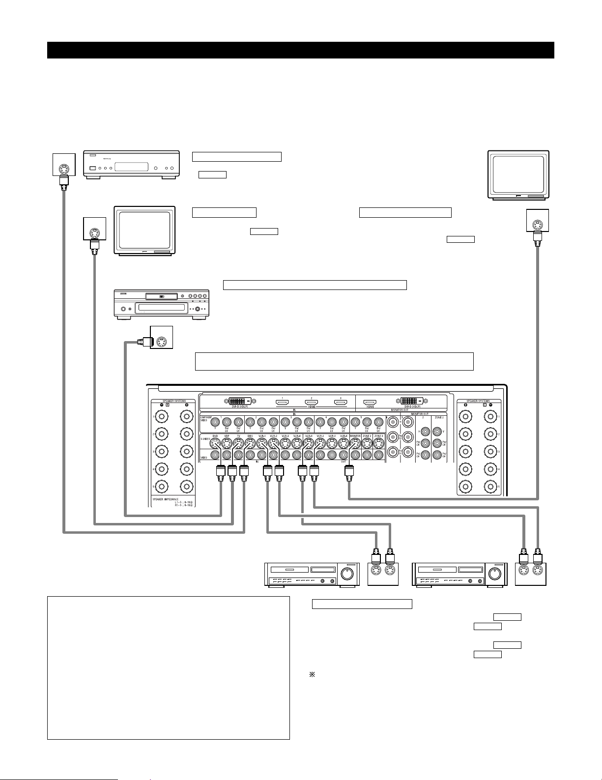
Connecting video components equipped with S-Video jacks
• When making connections, also refer to the operating instructions of the other components.
• A note on the S-Video input jacks
The input selectors for the S-Video inputs and Video inputs work in conjunction with each other.
• The AVC-A1XV is equipped with a function for converting video signals. (See page 13)
The signal connected to the S-Video signal terminal is output to the composite video and component video monitor out terminals.
But the REC OUT terminals have no conversion function, so when recording connect the S-Video terminals.
OUT
S-VIDEO
OUT
S-VIDEO
OUT
S-VIDEO
IN
S-VIDEO
OUT IN
S-VIDEO
OUT IN
S-VIDEO
B
Monitor TV
Video deck 2Video deck 1
TV
Connecting a monitor TV
Connecting the video decks
Connecting a TV
MONITOR OUT
• Connect the TV’s or DBS tuner’s S video input
(S-VIDEO INPUT) to the MONITOR
OUT jack using a S jack connection cord.
S-VIDEO
• Connect the TV’s S video output jack (S-VIDEO
OUTPUT) to the TV IN jack using an S
jack connection cord.
S-VIDEO
• Connect the video deck’s S output jack (S-OUT) to the VCR-1 IN
jack and the video deck’s S input jack (S-IN) to the VCR-1 OUT jack
using S jack connection cords.
• Connect the video deck’s S output jack (S-OUT) to the VCR-2 IN
jack and the video deck’s S input jack (S-IN) to the VCR-2 OUT jack
using S jack connection cords.
Connect the third and fourth video deck to the VCR-3 and VCR-4 jacks in the
same way.
S-VIDEO
S-VIDEO
S-VIDEO
S-VIDEO
Connect the components’ audio inputs and outputs as described on page 10.
NOTES:
• The video signal ZONE2 MONITOR OUT (yellow), S-Video
signal ZONE2 MONITOR OUT jack or component signal ZONE2
MONITOR OUT output switches together with the input
function selected with the ZONE2 SELECT (See page 152). To
use as the monitor output, set “SOURCE” as the ZONE2 input
function. The on-screen display signals are output from the
ZONE2 MONITOR OUT (See pages 147~149).
• The video signal ZONE3 MONITOR OUT (yellow) or S-Video
signal ZONE3 MONITOR OUT output switches together with
the input function selected with the ZONE3/REC SELECT (See
page 152). To use as the monitor output, set “SOURCE” as the
ZONE3/REC SELECT input function. At this time, the on-screen
display signals are not output from the ZONE3 MONITOR OUT
(See page 150).
DVD player or video disc player (VDP)
Connecting a DVD player or a video disc player (VDP)
DVD
• Connect the DVD player’s S-Video output jack to the S-VIDEO DVD IN jack using a S-Video
connection cord.
• VDP can be connected to the VDP jacks in the same way.
• It is also possible to connect a video disc player, DVD player, video camcorder, game machine,
etc., to the V.AUX jacks.
Connecting a DBS tuner
• Connect the DBS tuner’s S video output jack (S-VIDEO OUTPUT) to the
DBS IN jack using an S-Video connection cord.
S-VIDEO
DBS tuner
Page 13
13
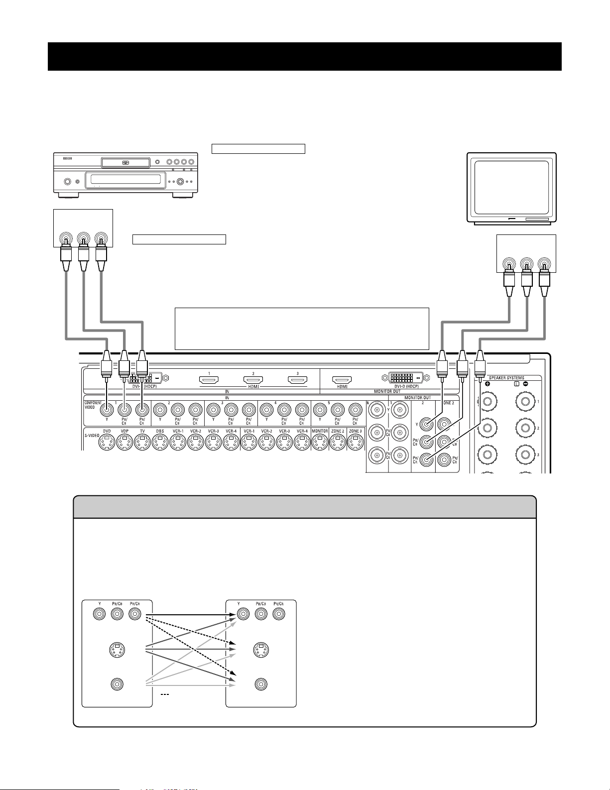
Connecting video components equipped with Component Video (color difference) video jacks
(Component - Y, P
B, PR ; Y, CB, CR)
• When making connections, also refer to the operating instructions of the other components.
• The signals input to the component (color difference) video jacks are not output from the VIDEO output jack (yellow) or the S-Video output jack.
• Some video sources with component video outputs are labeled Y, P
B, PR, or Y, CB, CR, or Y, B-Y, R-Y. These terms all refer to component video
color difference output.
• The function assigned to the component video input can be changed at the system setup. For details, see “Setting the Component In Assign”.
(See pages 66, 67)
YPB PR
VIDEO IN
COMPONENT
YPB PR
VIDEO OUT
COMPONENT
DVD player Monitor TV
Connecting a DVD player
Connecting a monitor TV
DVD IN jacks
• Connect the DVD player’s component (color difference) video output jacks
(COMPONENT VIDEO OUTPUT) to the COMPONENT DVD IN jack using 75
Ω/ ohms coaxial video pin-plug cords.
• In the same way, another video source with component video outputs such
as a DTV/DBS tuner, etc., can be connected to the TV/DBS component
(color difference) video jacks.
MONITOR OUT jack
• Connect the TV’s component (color difference) video input jacks (COMPONENT VIDEO INPUT) to the
COMPONENT MONITOR OUT-2 jack using 75 Ω/ohms coaxial video pin-plug cords.
• Connect the TV’s component (color difference) video input jacks (COMPONENT VIDEO INPUT) to the
COMPONENT MONITOR OUT-1 jack using BNC connectors.
• The COMPONENT MONITOR OUT-1 and the COMPONENT MONITOR OUT-2 can be used simultaneously.
• The component video input and/or output jacks may be labeled differently
on some TVs, monitors or video components (Y, P
B, PR; Y, CB, CR; Y, B-Y, R-
Y). Check the owner’s manuals for other components for further
information.
(MONITOR OUT / ZONE2)
(MONITOR OUT / ZONE2)
(MONITOR OUT / ZONE2)
The Video Conversion Function
The AVC-A1XV is equipped with a function for up and down converting video signals.
Because of this, the AVC-A1XV’s MONITOR OUT jack can be connected to the monitor (TV) with a set of cables offering a higher
quality connection, regardless of how the player and the AVC-A1XV’s video input jacks are connected.
Generally speaking, connections using the component video jacks offer the highest quality playback, followed by connections
using the S-Video jacks, then connections using the regular video jacks (yellow).
This unit’s input jacks This unit’s output jacks
The flow of the video signals.
(Component Video Jacks)
(S-Video jack)
(Video jack)
(Component Video Jacks)
(S-Video jack)
(Video jack)
Cautions on the ZONE2 video conversion function:
There is no TBC (Time Base Collector) for ZONE2.
When the component video terminals are used to connect
the AVC-A1XV with a TV (or monitor, projector, etc.) and the
video (yellow) or S video terminals are used to connect the
AVC-A1XV with a VCR, depending on the combination of the
TV and VCR the picture may flicker in the horizontal
direction, be distorted, be out of sync or not display at all
when playing video tapes.
If this happens, connect a commercially available video
stabilizer, etc., with a TBC (time base corrector) function
between the AVC-A1XV and the VCR, or if your VCR has a
TBC function, turn it on.
(:
only MAIN ZONE
480i/580i )
Page 14
14
NOTES:
•Video down conversion to the MAIN ZONE’s monitor output is only possible when the component video input resolution is 480i
(interlaced standard definition video – NTSC format, for North America) or 576i (interlaced standard definition video – PAL format, for
Europe and other countries).
• This video conversion function cannot be used with HDMI or DVI video signals.
•To change the setting of the video conversion mode for the MAIN ZONE, see pages 67, 68.
To change the setting of the video conversion mode for the ZONE2, see pages 88, 89.
• It is not possible to down-convert from the ZONE2’s component video signal to a S-Video or composite signal, so when not using the
ZONE2’s component monitor output connector, use an S-Video connection cord or composite connection cord to connect the AVC-A1XV
with the player.
OUT
HDMI
(HDCP)
HDMI IN
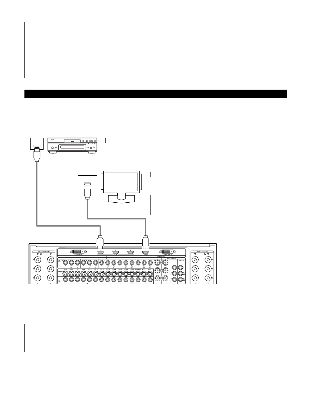
Connecting equipment with HDMI (High-Definition Multimedia Interface) terminals
•A simple 1-cable connection (using a commercially available cable) with a device having an HDMI (High-Definition Multimedia Interface) connector
allows digital transfer of the digital images of DVD video and other sources, and the multi-channel sound of DVD audio and DVD video.
• The HDMI and DVI-D monitor output connectors on the AVC-A1XV can only be used one at a time, not simultaneously.
•To provide audio output from AVC-A1XV’s audio output connector, select “Amp” at the System Setup.
•To provide audio output from the TV, select “TV” at the System Setup. For details, see “Setting the HDMI/DVI In Assign”. (See pages 70, 71)
Connecting a monitor TV
HDMI MONITOR OUT terminal
• Connect the TV’s HDMI input terminals to the HDMI OUT terminal using HDMI
cable.
Connecting a DVD player
HDMI IN terminals
• Connect the DVD player’s HDMI output terminals to the HDMI IN terminal using HDMI cable.
•
Among the devices that support HDMI, some devices can control other devices via the HDMI connector; however, the
AVC-A1XV
cannot be controlled by another device via the HDMI connector.
•
The audio signals from the HDMI connector (including the sampling frequency and bit length) may be limited by the equipment that is
connected.
•
The on-screen display signals are not outputted from the HDMI MONITOR OUT.
HDMI cable
(commercially available)
To play back the digital video and audio of DVD video and DVD audio through an HDMI/DVI-D connection, both the connected player
and monitor are required to support a copyright protection system called HDCP (High-bandwidth Digital Content Protection System).
HDCP is copy protection technology that comprises data encryption and authentication of the partner equipment. The AVC-A1XV supports
HDCP. Please see the user’s manual of your video display for more information about this.
Copyright Protection System
DVD player
Monitor equipped with
HDMI input connectors
HDMI cable
(commercially available)
NOTE:
• The audio signals on the multi/stereo area of super audio CDs are not output.
Use a compatible player to play DVD audio discs that are copyright protected by
CPPM.
Page 15
15
OUT
DVI-D
(HDCP)
DVI-D IN
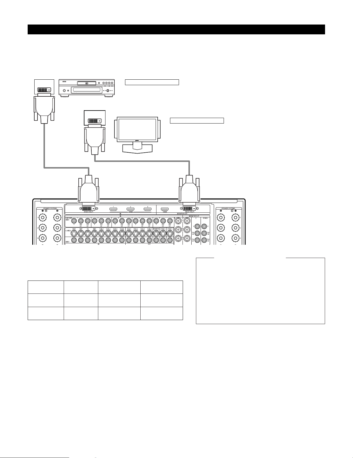
Connecting equipment with DVI (Digital Visual Interface) terminals
• Connection with equipment that has a DVI (Digital Visual Interface)-D connector permits the transfer of digital images. Make an audio
connection also.
• Commercially-available DVI cables are available in 24-pin and 29-pin types. The AVC-A1XV supports the 24-pin DVI-D cable.
• The HDMI and DVI-D monitor output connectors on the AVC-A1XV can only be used one at a time, not simultaneously.
• The on-screen display signals are not outputted from the DVI-D MONITOR OUT.
Connecting a monitor TV
DVI-D MONITOR OUT terminal
• Connect the TV’s DVI-D input terminal to the DVI-D MONITOR OUT terminal using
DVI-D cable.
Connecting a DVD player
DVI-D IN terminal
• Connect the DVD player’s DVI-D output terminals to the DVI-D IN terminal using DVI-D cable.
Note on connecting a HDMI/DVI
•
The table below indicates the compatibility of connections between
the HDMI/DVI-D output connector of the
AVC-A1XV and monitors that
support HDMI/DVI-D.
24P DVI-D cable
(commercially available)
E
E
HDMI output
terminal
Monitor with
HDMI
C
(Video / Audio)
C
(Only Video)
DVI-D output
terminal
Monitor with DVI-D
(HDCP compatible)
C
(Only Video)
C
(Only Video)
Monitor with DVI-D
(HDCP incompatible)
24P DVI-D cable
(commercially available)
DVD player
Monitor equipped with
DVI-D input connectors
To play back the digital video and audio of DVD video
and DVD audio through an HDMI/DVI-D connection,
both the connected player and monitor are required to
support a copyright protection system called HDCP
(High-bandwidth Digital Content Protection System).
HDCP is copy protection technology that comprises data
encryption and authentication of the partner equipment.
The AVC-A1XV supports HDCP. Please see the user’s
manual of your video display for more information about
this.
Copyright Protection System
Page 16
16
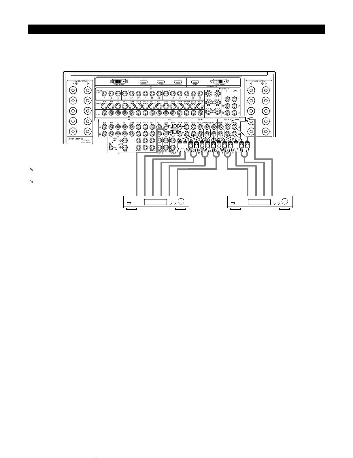
Connecting the external input (EXT. IN) jacks
•AVC-A1XV is equipped with two analog external input terminals for 9.1 channels and 5.1 channels.
• These jacks are for inputting multi-channel audio signals from an outboard decoder, or a component with a different type of multi-channel
decoder, such as a DVD Audio player, or a multi-channel SACD player, or other future multi-channel sound format decoder.
• When making connections, also refer to the operating instructions of the other components.
LRL
R
L
R
LRL
R
L
R
Decoder with 10-, 8- or 6-channel analog output
Front
Surround back
Surround A
Subwoofer
Center
For instructions on playback using the
external input (EXT. IN) jacks, see page 123.
See pages 59, 60 for “Setting the EXT.IN
Setup”.
Surround B
Surround
Subwoofer
Front
Center
Decoder with 6-channel analog output
Page 17
17
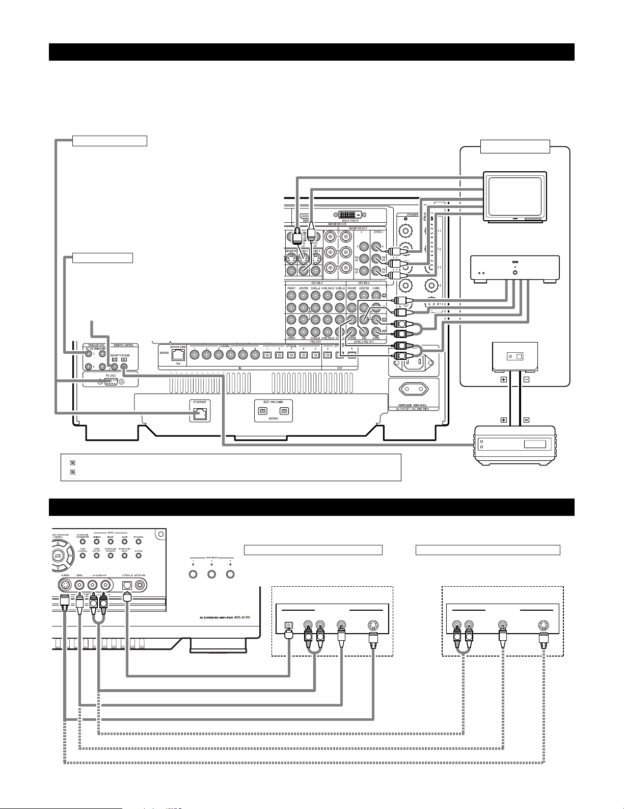
Connecting the ZONE2 jacks
L
R
R
L
OUTPUT
INPUT
AUX OUT
Another room
INFRARED RETRANSMITTER
Power amplifier
INFRARED SENSOR
Extension jacks for future use.
For instructions on operations using the MULTI ZONE jacks, see pages 146~160.
See pages 150, 151 for the connection method of ZONE3 and ZONE4.
Connecting a component with video and audio jacks to the V.AUX input jacks
•To connect the video signal, connect using a 75 Ω/ohms video signal cable cord.
R VIDEO OUT S-VIDEO OUTOPTICAL L
OUTPUT
R VIDEO OUT S-VIDEO OUTL
OUTPUT
LINE OUT
VIDEO OUT
S-VIDEO OUT
LINE OUT
DIGITAL OUT
VIDEO OUT
S-VIDEO OUT
L R
R
L
R
L
Connecting a Video game component
• Connect the Video game component’s output
jacks to this unit’s V. AUX INPUT jacks.
Video game Video camera
Connecting a video camera component
• Connect the video camera component’s output
jacks to this unit’s V. AUX INPUT jacks.
TRIGGER OUT
Turn the DC 12V voltage on and off for the individual functions
and surround modes.
For details, see “Setting the Trigger Out”. (See pages 102, 103)
CONTROL terminal
These terminals are used for an exteral controller.
Perform the following operation before using an external
controller connected to the RS-232C terminal:
1. Press the ON/STANDBY button on the main unit and set
the unit to the operating mode.
2. Perform the operation to turn off the power from the
external control.
3. Check that the product has been set to the standby
mode.
After checking the above, check the connections of the
external controller. Operation is possible.
TV
2 ZONE2 preout CONNECTIONS
• If another power amplifier is connected, the ZONE2 preout (variable level) jacks can be used to play a different program source in ZONE2 the
same time. (See page 147)
• The ZONE2 video out is only use for the ZONE2.
• The connection diagram below is an example of multi-channel playback in ZONE2. Please see page 149 when you would like to have 2channel playback in ZONE2.
Page 18
18
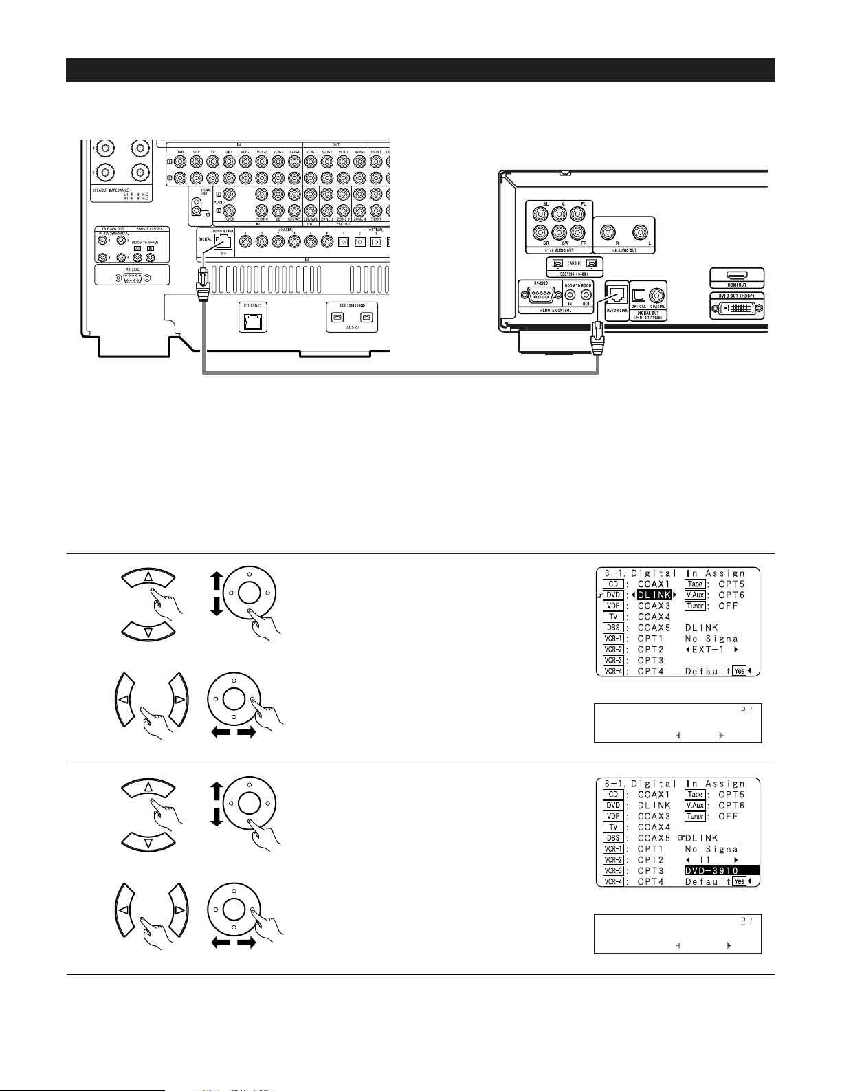
2 DENON LINK Setting
When a DENON DVD player and the DENON LINK have been connected, be sure to make a setting to “DENON LINK” with the System Setup
Digital In Assignment. (See pages 57, 58)
• When the input mode is AUTO and the signals are not be able to transferred by DENON LINK, the unit automatically changes over the input
to the selected signals (ANALOG, EXT. IN or IEEE1394).
1
Assign DENON LINK to the input source.
q Select the input source.
2
CH SEL
ENTER
2 Playback using the DENON LINK connector
Digital transfer and multi-channel playback of DVD audio discs and other multi-channel sources is possible by connecting the AVC-A1XV to a
DENON DVD player equipped with a DENON LINK connector using the connection cable included with the DVD player.
CH SEL
ENTER
w Select “DLINK”.
CH SEL
ENTER
CH SEL
ENTER
w Select input signal (ANALOG, EXT.IN or IEEE1394).
DVD : DLINK
*Digital In
NoSig.: I1
*Digital In
(Main unit) (Remote control unit)
(Main unit) (Remote control unit)
(Main unit) (Remote control unit)
(Main unit) (Remote control unit)
DENON LINK connections
• High quality digital sound with reduced digital signal transfer loss can be enjoyed by connecting a separately sold DENON LINK compatible DVD
Player.
DVD player
Select the input for the playback of signals that cannot
be transferred by DENON LINK.
q Select “DLINK” setting.
Page 19
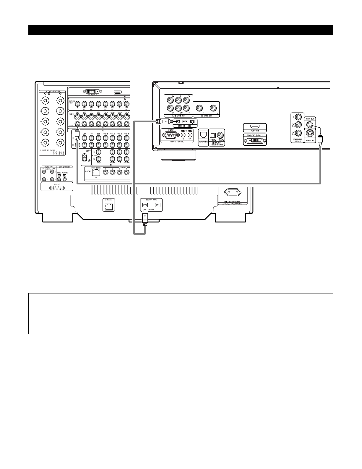
19
2 IEEE1394 network
q Up to 17 devices can be connected using daisy chain type connections.
w Up to 63 devices can be connected using tree type connections.
Do not loop the connections.
e Select IEEE 1394 input. “LINK CHECK” will be displayed while the IEEE 1394 connection is being checked.
r If the connection is looped, “LOOP CONNECT” is displayed. Check the connections and undo the loop.
Connecting IEEE1394 devices
• Use an S400-compatible 4-pin IEEE1394 cable to connect.
•Video signals are not transferred with the AVC-A1XV’s IEEE1394 interface, so when connecting a video device connect the video signals as
well.
• Assign the IEEE1394 input the input source. (See page 64)
DVD player
NOTE:
• The AVC-A1XV will not operate when connected to equipment other than that conforming to “IEEE1394 AUDIO (A&M protocol)”
standards or when connected to computer peripherals.
Also please note that operation is not guaranteed even when connected to IEEE1394-compatible equipment. Whether or not data and
control signals can be sent and received between interconnected IEEE1394-compatible equipment depends on the functions of the
different equipment. Please read the operating instructions of the equipment to be connected.
Page 20
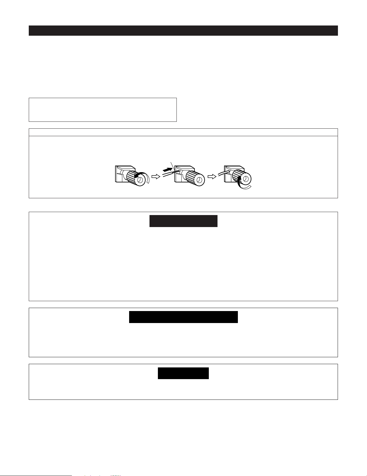
20
Speaker system connections
• Connect the speaker terminals with the speakers making sure that
like polarities are matched (< with < , > with >). Mismatching of
polarities will result in weak central sound, unclear orientation of
the various instruments, and the sense of direction of the stereo
being impaired.
• When making connections, take care that none of the individual
conductors of the speaker cord come in contact with adjacent
terminals, with other speaker cord conductors, or with the rear
panel.
Speaker Impedance
• Speakers with an impedance from 6 to 16 Ω/ohms can be
connected.
•The protector circuit may be activated if the set is played for long
periods of time at high volumes when speakers with an impedance
lower than the specified impedance are connected.
NOTE:
NEVER touch the speaker terminals when the power is on.
Doing so could result in electric shocks.
Connecting the speaker cords
1. Loosen by turning
counterclockwise.
2. Insert the cord. 3. Tighten by turning
clockwise.
Either tightly twist or terminate the core wires.
Protector circuit
• This unit is equipped with a high-speed protection circuit. The purpose of this circuit is to protect the speakers under
circumstances such as when the output of the power amplifier is inadvertently short-circuited and a large current flows,
when the temperature surrounding the unit becomes unusually high, or when the unit is used at high output over a long
period which results in an extreme temperature rise.
When the protection circuit is activated, the speaker output is cut off and the power supply indicator LED flashes. Should
this occur, please follow these steps: be sure to switch off the power of this unit, check whether there are any faults
with the wiring of the speaker cables or input cables, and wait for the unit to cool down if it is very hot. Improve the
ventilation condition around the unit and switch the power back on.
If the protection circuit is activated again even though there are no problems with the wiring or the ventilation around the
unit, switch off the power and contact a DENON service center.
Note on speaker impedance
• The protector circuit may be activated if the set is played for long periods of time at high volumes when speakers with
an impedance lower than the specified impedance (for example speakers with an impedance of lower than 4 Ω/ohms)
are connected. If the protector circuit is activated, the speaker output is cut off. Turn off the set’s power, wait for the set
to cool down, improve the ventilation around the set, then turn the power back on.
Cooling fan
• The AVC-A1XV is equipped with a cooling fan to prevent the temperature inside the set from rising. The fan is activated
under certain usage conditions. It is temperature sensitive, to minimize or prevent audible fan noise.
Page 21
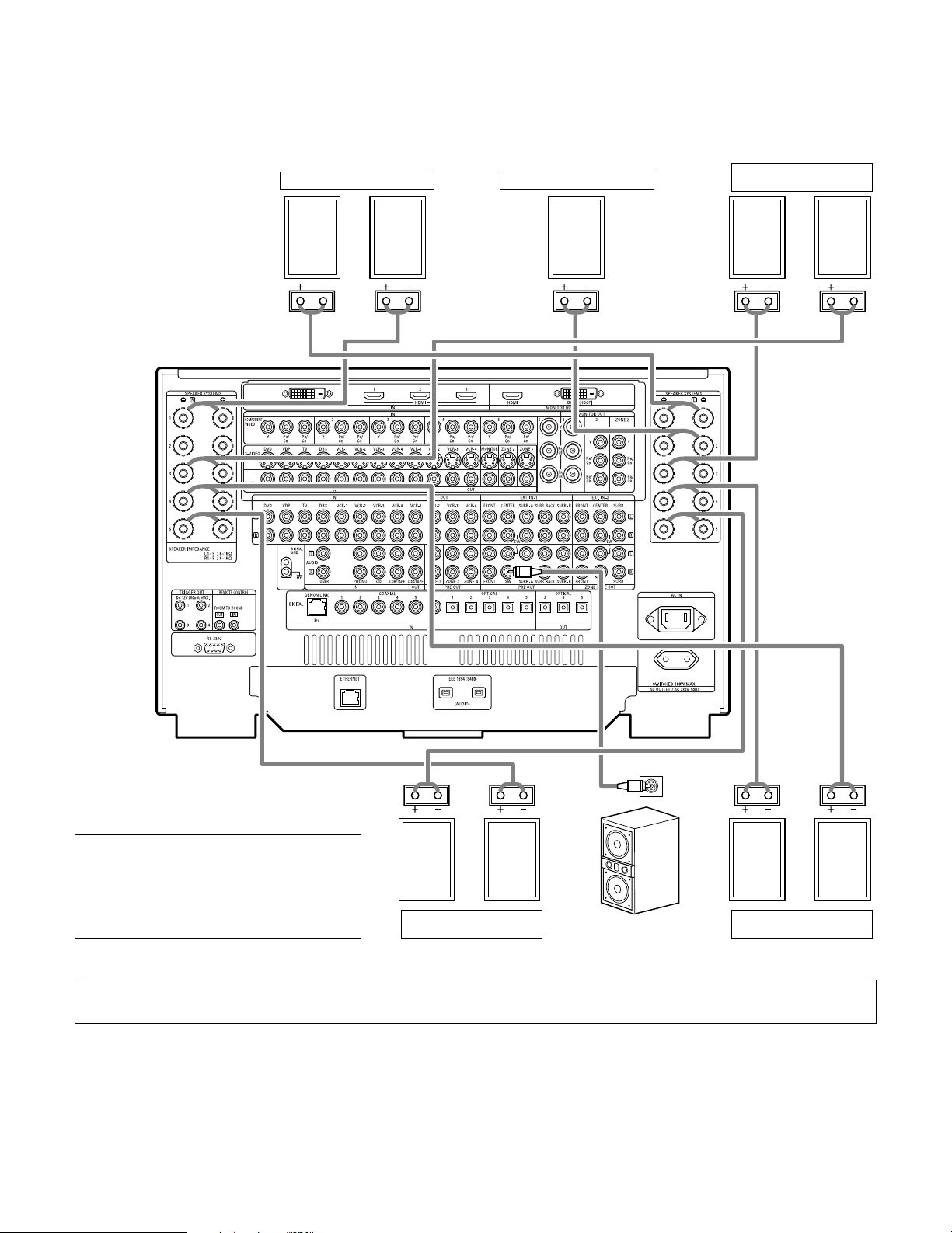
21
Connections
• By default, the speaker system setting is set to 9.1 channels.
• The output of each power amplifier can be assigned to any desired channel to best suit the application.
For details, refer to “Setting the Channel Setup” and “Setting the Power Amplifier Assignment”. (See pages 92~100)
• When making connections, also refer to the operating instructions of the other components.
IN
(L) (L) (R) (R)
(L) (R) (L) (R)
Connection jack for
subwoofer with built-in
amplifier (subwoofer), etc.
SURROUND SPEAKER
SYSTEMS (A)
CENTER SPEAKER SYSTEMFRONT SPEAKER SYSTEMS
• Precautions when connecting speakers
If a speaker is placed near a TV or video monitor, the
colors on the screen may be disturbed by the
speaker’s magnetism. If this should happen, move
the speaker away to a position where it does not
have this effect.
SURROUND SPEAKER
SYSTEMS (B)
SURROUND BACK
SPEAKER SYSTEMS
NOTE:
• When using only one surround back speaker, connect it to left channel (L5).
Page 22
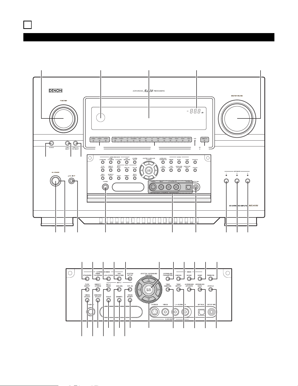
22
6
PART NAMES AND FUNCTIONS
Front Panel
• For details on the functions of these parts, refer to the pages given in parentheses ( ).
!4 !3 !2 !1 !0
q w e r t y u i o
!5 !6 !7
!8 !9
@0$8
#7 #9 $1 $2#5
#4#2 #6 #8 $0
#3
$7$5$3 $6$4
@2@1 @3 @4 @5 @8@7@6 @9 #0 #1
Page 23

23
q
Power ON/STANDBY switch.................................................(120)
w
Power indicator......................................................................(120)
e
Power switch.................................................................(120, 160)
r
Headphones jack (PHONES)..................................................(125)
t
V.AUX INPUT jacks ..................................................................(17)
y
SETUP MIC jack ......................................................................(32)
u
USER MODE 1 button...........................................................(141)
i
USER MODE 2 button...........................................................(141)
o
USER MODE 3 button...........................................................(141)
!0
MASTER VOLUME control....................................................(122)
!1
Master volume indicator........................................................(122)
!2
Display
!3
Remote control sensor ..........................................................(108)
!4
FUNCTION knob............................................(121, 127, 128, 152)
!5
SOURCE button.....................................................................(121)
!6
ZONE2 SELECT button..........................................................(152)
!7
ZONE3/4/REC SELECT button ..............................(127, 128, 152)
!8
Multi Zone power indicators..................................................(153)
!9
Input source indicators ..........................................................(121)
@0
MultEQ XT indicator ..............................................................(125)
@1
STANDARD button........................................................(135~139)
@2
HOME THX CINEMA button .........................................(132, 134)
@3
9CH STEREO button .............................................................(143)
@4
DSP SIMULATION button .....................................................(143)
@5
SYSTEM SETUP button...........................................................(26)
@6
CH SELECT/ENTER button......................................(26, 129, 130)
@7
SURROUND PARAMETER button.........................................(132)
@8
CINEMA button .............................................................(137, 139)
@9
MUSIC button................................................................(137, 139)
#0
GAME button.........................................................................(137)
#1
ROOM EQ button..................................................................(125)
#2
PURE DIRECT button ............................................................(124)
#3
VIDEO SELECT button ..........................................................(125)
#4
DIRECT/STEREO button........................................................(124)
#5
MONITOR SELECT button ....................................................(126)
#6
INPUT MODE button.............................................................(121)
#7
SCALE button ........................................................................(127)
#8
ANALOG button.....................................................................(121)
#9
DIMMER button ....................................................................(126)
$0
EXT.IN button.................................................................(121, 123)
$1
VIDEO ON/OFF button ..........................................................(124)
$2
CURSOR button.......................................................................(26)
$3
TONE CONTROL button........................................................(145)
$4
TONE DEFEAT button ...........................................................(145)
$5
SURROUND SPEAKER button ..............................................(126)
$6
SURROUND BACK button.............................................(134, 135)
$7
STATUS button ......................................................................(126)
$8
Extension indicator for future use
Page 24
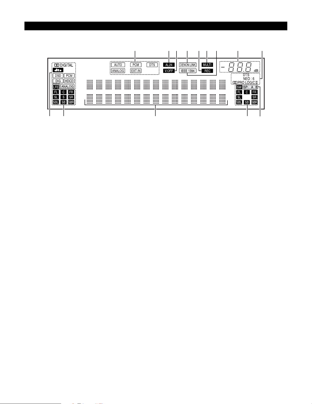
24
Display
u yo!0!1!3!2!4 i
e
r t
q
w
q
INPUT SIGNAL indicator
The respective indicator will light corresponding to the input
signal.
w
INPUT SIGNAL CHANNEL indicator
The channels included in the input source will light.
This lights when the digital signal is inputted.
e
Information display
This displays the surround mode, function name or setting
value, etc.
r
OUTPUT SIGNAL CHANNEL indicator
The audio channels that can be output light.
t
SPEAKER indicator
This lights corresponding to the settings of the surround
speakers of the various surround modes.
y
Decoder indicator
This lights when each decoder is operating.
u
MASTER VOLUME indicator
This displays the volume level.
The Setup item number is displayed in System Setup.
i
IEEE1394 indicator
This lights during playback in a IEEE1394 connection.
o
MULTI (ZONE) indicator
ZONE3 mode is selected in ZONE3/REC SELECT.
!0
REC OUT SOURCE indicator.
REC OUT mode is selected in ZONE3/REC SELECT.
!1
DENON LINK indicator
This lights during playback in a DENON LINK connection.
!2
V.OFF indicator
This lights when the operation of the video circuit has been
turned off.
!3
AL24 indicator
The AL24 indicator lights when the PURE DIRECT, DIRECT,
STEREO, MULTI CH PURE DIRECT , MULTI CH DIRECT, MULTI
CH IN mode is selected in the PCM input signal.
!4
INPUT MODE indicator
This lights corresponding to the setting of the INPUT mode.
Page 25
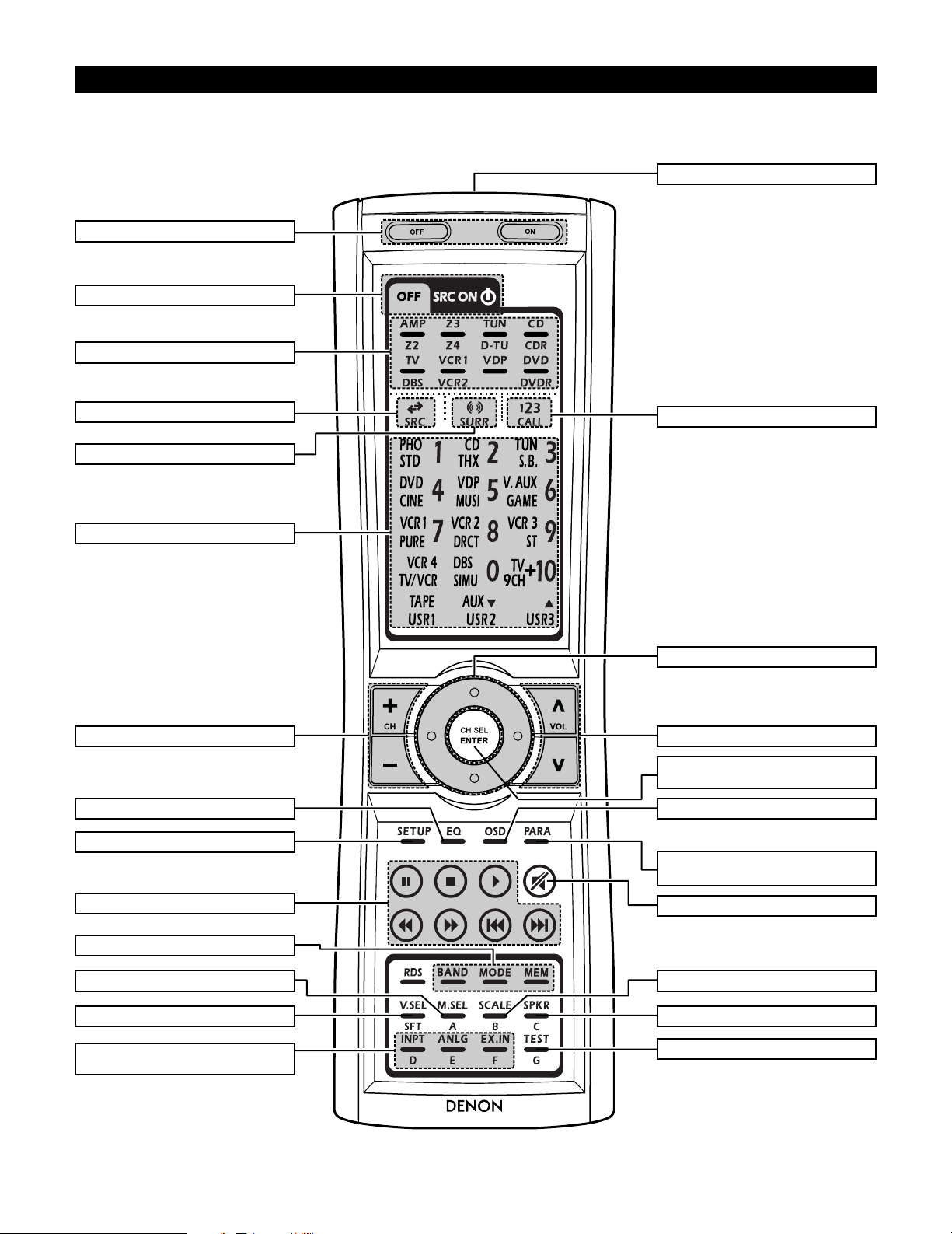
25
RC-995
Remote control unit
• For details on the functions of these parts, refer to the pages given in parentheses ( ).
Cursor buttons........................................(26)
Power buttons......................................(120)
10KEY/SYSTEM CALL button ..............(109)
SURROUND PARAMETER button
.....................................................(132, 157)
Master volume control buttons....(122, 153)
ON SCREEN button .............(126, 133, 153)
INPUT MODE selector buttons
.............................................(121~123, 153)
VIDEO SELECT button.................(125, 153)
Tuner system buttons ..........................(110)
SYSTEM buttons..........................(109, 110)
Input source button..............................(109)
Mode selector buttons.........................(109)
Remote control signal transmitter........(108)
SYSTEM buttons..................................(153)
MUTING button............................(125, 153)
Surround mode button .........................(109)
SYSTEM SETUP button .................(26, 154)
ROOM EQ button ................................(125)
CH SELECT/ENTER button
...............................(26, 129, 130, 155, 156)
SCALE button.......................................(127)
SPEAKER button ..................................(126)
TEST TONE button.......................(129, 154)
MONITOR SELECT button...................(126)
Tuner system buttons ..........................(110)
SYSTEM buttons..........(109, 110, 112, 113)
Page 26
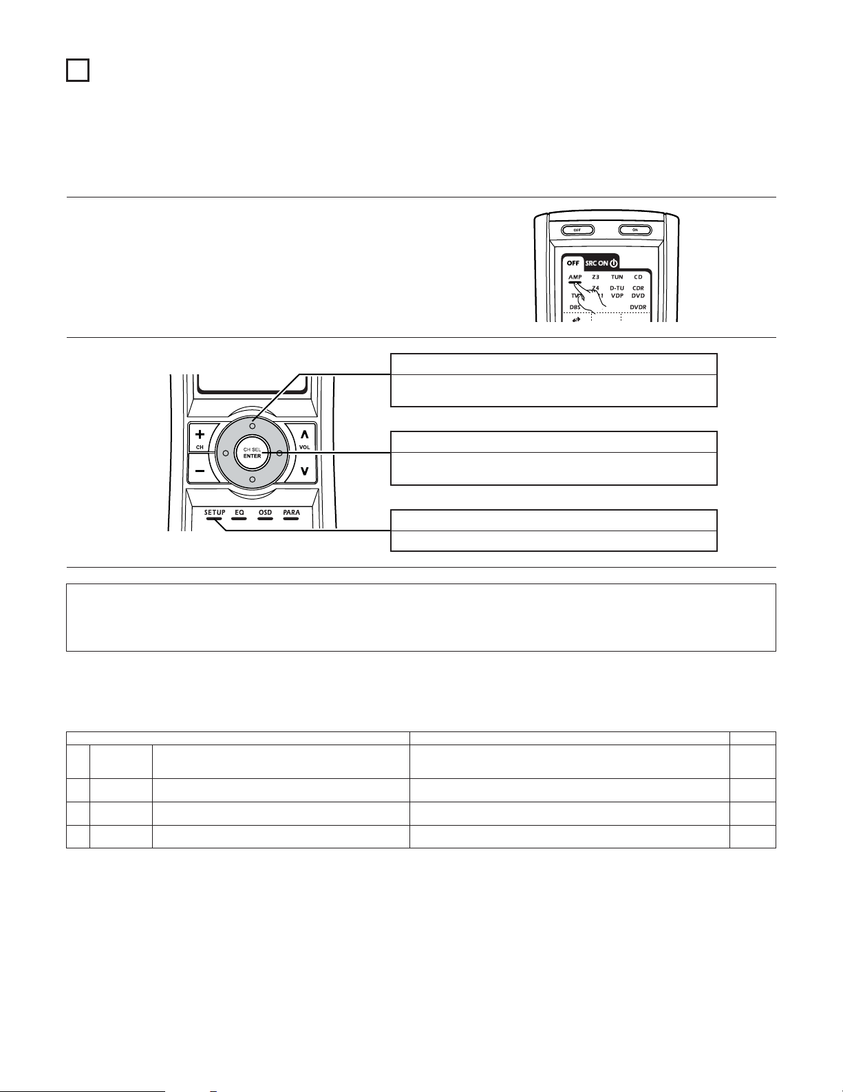
26
7
SYSTEM SETUP
• Once all connections with other AV components have been completed as described in “CONNECTIONS” (see pages 9~21), make the various
settings described below on the monitor screen using the AVC-A1XV’s on-screen display function.
These settings are required to set up the listening room’s AV system centered around the AVC-A1XV.
SYSTEM SETUP button
Press this to display the system setup menu.
ENTER button
Press this to switch the display.
Also use this button to complete the setting.
CURSOR buttons
Use these to move the cursors the left, right, up and down on
the screen.
1
Check that the remote control unit set to AMP mode.
2
2 Use the following buttons to set up the system
2 System setup items and default values (set upon shipment from the factory)
1. Auto Setup/Room EQ
Auto Setup / Room EQ Default settings
1
Auto Setup
Room EQ
Setup
2
Direct Mode
Setup
4
Set the ON/OFF setting of Room EQ, in the case of the surround
mode is in Direct or Pure Direct.
3
Mic Input
Select
Set this to switch the Mic Input jack for use for Mic or V.AUX Lchannel input jack.
This unit performs an analysis of the speaker system and measures
the acoustic characteristics of your room to permit an appropriate
automatic setting.
Set the Room EQ setting with All or Assign for each surround mode.
–
All, Room EQ = OFF
OFF
Mic
Page
33~39
40, 41
41
42
NOTES:
• The AVC-A1XV’s on-screen display function is designed for use with high resolution monitor TVs, so it may be difficult to read small
characters on TVs with small screens or low resolutions.
• The setup menu is not displayed when headphones are being used.
Page 27
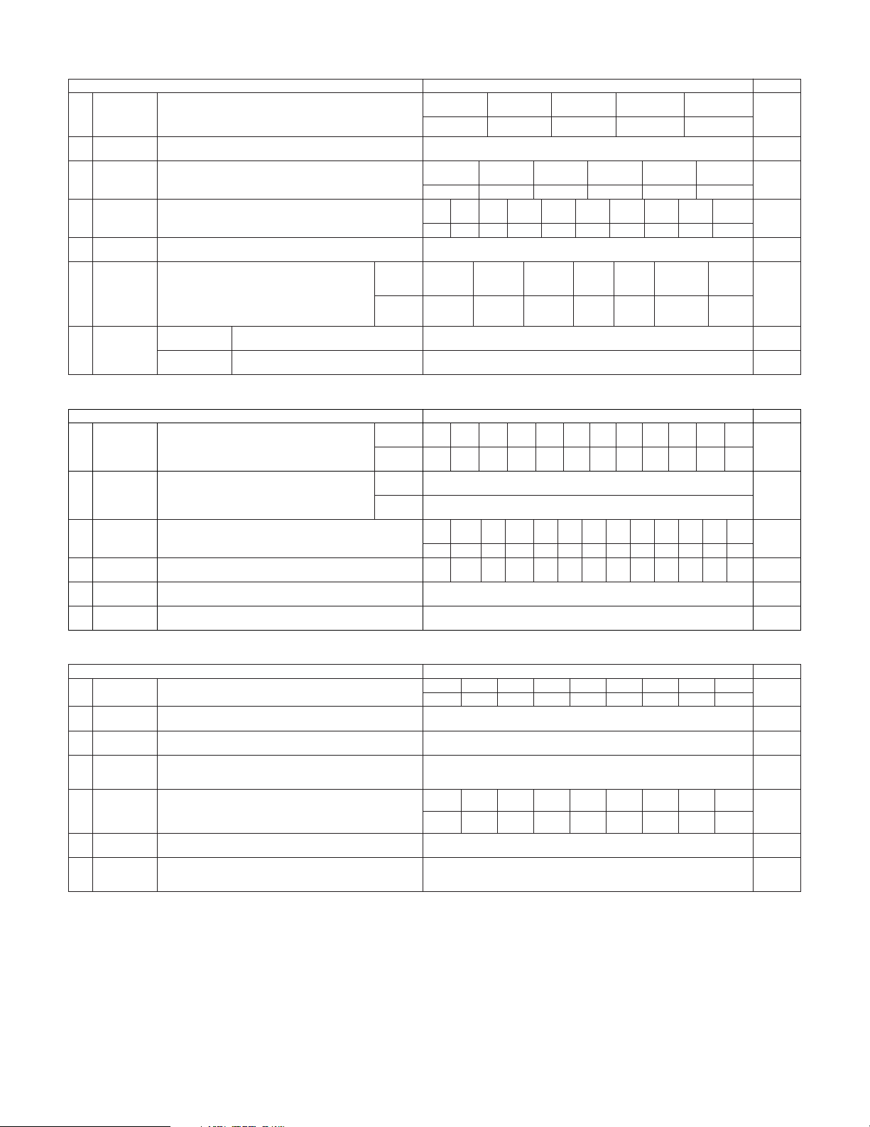
27
3. Audio Input Setup
Audio Input Setup Default settings Page
57, 58
Digital In
Assign
This assigns the digital input jacks for the different input
sources.
Input
source
Digital
Inputs
CD DVD VDP TV DBS VCR-1 VCR-2
COAX 1COAX 2COAX 3COAX 4COAX
5
OPT 1
OPT 2
1
CDR/
TAPE
OPT 5
VCR-3 VCR-4
OPT 3 OPT 4
V.AUX
OPT 6
2
EXT.IN Setup Set the Ext.In terminal playback method.
EXT.IN-1
Setup
EXT.IN-2
Setup
Mode = DSP, Surr.B = NOT USED, S.Back = NOT USED,
SW Level = +15 dB, Input ATT. = OFF
Mode = DSP, SW Level = +15 dB, Input ATT. = OFF
61
Input Function
Lev.
The playback level is corrected individually for the different input
sources.
TUNER PHONO CD
CDR/
TAPE
DVD VDP TV
0 dB 0 dB 0 dB 0 dB 0 dB 0 dB 0 dB
3
VCR-2
0 dB
DBS VCR-1
0 dB 0 dB
VCR-3
0 dB
VCR-4
0 dB
V.AUX
0 dB
4
Function
Rename
The names of the different input source can be changed as desired
and displayed on the display.
62, 63
5
IEEE1394
Assign
The connected IEEE1394 device can be automatically identified to
assign the input source.
–64
6
IEEE1394
Auto Func.
Set the function for associating playback of the connected IEEE1394
device on or off.
Auto Function = OFF 65
59, 60
TUNER PHONO CD
CDR/
TAPE
DVD VDP TV
VCR-2DBS VCR-1 VCR-3 VCR-4 V.AUX
2. Speaker Setup
Speaker Setup Default settings
1
3
Speaker
Configuration
Channel Level
Input the combination of speakers in your system and their
corresponding sizes (SMALL for regular speakers, LARGE for fullsize, full-range) to automatically set the composition of the signals
output from the speakers and the frequency response.
This adjusts the volume of the signals output from the speakers and
subwoofer for the different channels in order to obtain optimum
effects.
Front Sp.
Small
Center Sp.
Surround Sp.
A / B
Subwoofer
Small SmallYe s
Front L & R Center
Surround
L & R (A)
Subwoofer
3.6 m (12 ft) 3.6 m (12 ft) 3.0 m (10 ft)3.6 m (12 ft)
Front L Front R Center
Surround
R (A)
Surround
R (B)
Subwoofer
0 dB 0 dB 0 dB 0 dB
0 dB
0 dB
Surround Back
Sp.
Small / 2spkrs
4
Delay Time
This parameter is for optimizing the timing with which the audio
signals are produced from the speakers and subwoofer according to
the listening position.
Surround
L & R (B)
3.0 m (10 ft)
Surround
L (B)
0 dB
Surround
L (A)
0 dB
Crossover
Frequency
Set the frequency (Hz) below which the bass sound of the various
speakers is to be output from the subwoofer.
5
FIXED —THX—
Page
46, 47
2
Subwoofer
Setup
This selects the subwoofer for playing deep bass signals. LFE —THX— 47, 48
48, 49
50, 51
52, 53
Surround
Speaker Setup
Use this function when using multiple surround speaker
combinations for more ideal surround sound. Once the
combinations of surround speakers to be used for the
different surround modes are preset, the surround
speakers are selected automatically according to the
surround mode.
Surround
mode
Surround
speaker
THX/DOLBY/
DTS
CINEMA
THX/DOLBY/
DTS
MUSIC
WIDE
SCREEN
9 CH
STEREO
DSP
SIMULATION
MULTI CH
MODE
AAAA+B A+B A+B A
6
THX/DOLBY
GAME
54
7
THX Audio
Setup
When using a THX Ultra2 compatible subwoofer,
set the subwoofer’s frequency response.
THX Ultra2 Subwoofer = NO
Boundary Gain
compensation
Surround Back
Speaker Position
When using two surround back speakers, set
the distance of the two speakers.
The Distance Between SBL/SBR = 0 m to 0.3 m
55
Surround
Back
3.0 m (10 ft)
Surround
Back R
0 dB
Surround
Back L
0 dB
4. Video Setup
Video Setup Default settings
1
3
Component In
Assign
HDMI/DVI In
Assign
This assigns the color difference (component) video input jacks for
the different input sources.
The HDMI or DVI input terminals are assigned for the different input
sources.
Select HDMI or DVI for the monitor output terminal.
Select the HDMI audio signal playback method.
DVD VDP TV
5
Video Scaler
Make the settings related to video output (resolution and aspect rate
conversion).
Audio Delay Set the audio delay timing to synchronize the sound and video.
6
0 ms
Page
66, 67
2
Video Convert
Mode
Set the input signal to be output from the monitor output terminal. AUTO 67, 68
68, 69
70, 71
71, 72
On Screen
Display
This sets whether or not to display the on-screen display that
appears on the monitor screen when the controls on the remote
control unit or main unit are operated.
7
Function/Mode = ON, Master Volume = ON, Mode = Mode 1 72, 73
DBS VCR-1 VCR-2 VCR-3 VCR-4 V.AUX
1-RCA 2-RCA 3-RCA 4-RCA 5-RCA 6-BNC NONE NONE NONE
Aspect = FULL, Resolution = 480i / 576i
DVD VDP TV
DBS VCR-1 VCR-2 VCR-3 VCR-4 V.AUX
NONE NONE NONE NONE NONE NONE NONE NONE NONE
4
3D Y/C
Separation
This setting sets the action detection sensitivity of the 3-dimensional
Y/C separation at the time of the video signal up-conversion to SVideo.
69Motion Detection = MID
56
TUNER
OFF
Page 28
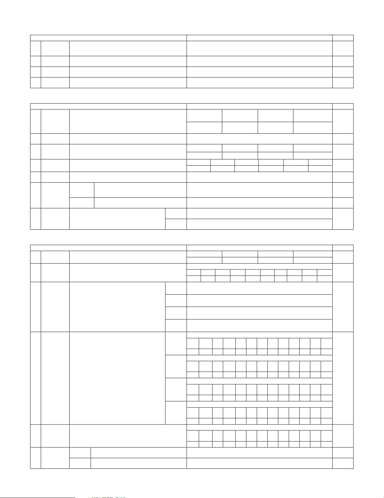
28
6. Zone Setup
Zone Setup Default settings
1
3
Speaker
Configuration
Channel Level
The components of the signals output from the various speakers and
the frequency response can be set automatically inside the set by
inputting the existence/absence of combinations of speakers and
their size (corresponding to their low frequency playback capability)
for the speakers used in ZONE2 during surround playback in ZONE2.
This adjusts the volume of the signal output from the various
speakers and subwoofer used in ZONE2.
Front Sp.
Small
Center Sp. Surround Sp.Subwoofer
Small SmallYes
Front L & R Center Surround L & RSubwoofer
3.6 m (12 ft) 3.6 m (12 ft) 3.0 m (10 ft)3.6 m (12 ft)
Front L Front R Center Surround R Subwoofer
0.0 dB 0.0 dB 0.0 dB 0.0 dB 0.0 dB
4
Delay Time
This parameter is for optimizing the timing of the sound produced
from the various speakers and subwoofer according to the listening
position in ZONE2.
Surround L
0.0 dB
Crossover
Frequency
Set the frequency (in Hz) below which deep bass appearing in the
main channels will be routed to the ZONE2 subwoofer.
5
80 Hz
Page
81
2
Subwoofer
Mode
This selects the subwoofer used in ZONE2 for playing the low base
sound.
LFE 82
83, 84
85, 86
87
Video Setup
Set the input signal to be output from the ZONE2
monitor out terminal.
Video
Convert
Mode
Audio Delay
6
88, 89
7
Zone3/4
Tone/Ch.Lev.
Adjust the tone and channel level of the sound output
from ZONE3 and ZONE4.
Bass = 0 dB, Treble = 0 dB, HPF = OFF, L/R = 0 dB
90, 91
Set the delay time the sound is synchronized with the
picture which are outputted in ZONE2.
AUTO
0 ms 89
Zone3
Zone4
Bass = 0 dB, Treble = 0 dB, HPF = OFF, L/R = 0 dB
7. Option Setup
Option Setup Default settings
1
3
Channel Setup
Trigger Out
Setup
The number of channels that you wish to play back in each zone are
assigned to each zone accordingly.
This sets the Trigger Out output for the different input
sources.
If “Zone=Main” is selected, settings can be made for
the individual surround modes.
Main Zone
9.1 CH
Zone2 Zone4Zone3
5.1 CH StereoStereo
4
Volume
Control
AC Outlet
Assign
This sets the AC outlet to on or off for the different input sources.
5
Page
92~95
2
Power Amp
Assign
Power Amplifiers can be assigned to the various channels according
to your system’s requirements.
Normal
96~100
102, 103
6
Setup
Memory/Lock
–105, 106
L1FLL2CL3
SLAL4SLBL5SBLR1FRR2–R3SRAR4SRBR5SBR
This sets the volume level of each zone output.
Volume Limit: This sets the upper limit for the
master volume.
Power On Level: This sets the volume level upon
switching on the power of each
zone.
Mute Level: This sets the amount of attenuation
of the audio output when each
zone is muted.
Volume Level: This se ts whether the output level
of ZONE2 to 4 is fixed or variable.
101, 102
Vol.Limit = OFF, P. On Lev. = LAST, Mute Lev. = FULL
Vol.Lev. = VAR, Vol.Limit = OFF, P. On Lev. = LAST, Mute Lev. = FULL
Vol.Lev. = VAR, Vol.Limit = OFF, P. On Lev. = LAST, Mute Lev. = FULL
Vol.Lev. = VAR, Vol.Limit = OFF, P. On Lev. = LAST, Mute Lev. = FULL
Trigger
Out 1
ZONE = MAIN, All Surround Modes = ON
TUNER PHONO CD
CDR/
TAPE
DVD VDP TV
OFF OFF OFF OFF ON ON ON
VCR-2
ON
DBS VCR-1
ON ON
VCR-3ONVCR-4ONV.AUX
ON
Trigger
Out 2
ZONE = 2
TUNER PHONO CD
CDR/
TAPE
DVD VDP TV
ON ON ON ON ON ON ON
VCR-2
ON
DBS VCR-1
ON ON
VCR-3ONVCR-4ONV.AUX
ON
Trigger
Out 3
ZONE = 3
TUNER PHONO CD
CDR/
TAPE
DVD VDP TV
ON ON ON ON ON ON ON
VCR-2
ON
DBS VCR-1
ON ON
VCR-3ONVCR-4ONV.AUX
ON
Trigger
Out 4
ZONE = 4
TUNER PHONO CD
CDR/
TAPE
DVD VDP TV
ON ON ON ON ON ON ON
VCR-2
ON
DBS VCR-1
ON ON
VCR-3ONVCR-4ONV.AUX
ON
104
ZONE = MAIN
TUNER PHONO CD
CDR/
TAPE
DVD VDP TV
ON ON ON ON ON ON ON
VCR-2
ON
DBS VCR-1
ON ON
VCR-3ONVCR-4ONV.AUX
ON
This stores the current user settings in the memory.
User
Memory
This sets whether or not to lock the system setup
settings so that thay cannot be changed.
Setup
Lock
Setup Lock = OFF
Main
Zone2
Zone3
Zone4
106, 107
5. Advanced Playback
Advanced Playback Default settings
1
2
2ch
Direct/Stereo
Auto Surround
Mode
Turn the audio compression on or off when down-mixing Dolby
Digital signals.
3
Dolby Digital
Setup
The speaker settings can be changed specifically for playing in the 2channel direct or stereo mode.
Set the Auto surround mode function.
Basic
OFF
Auto Surround Mode = ON
Page
74
75
76
4
This parameter is for optimizing the Room EQ with which the audio
signals are produced from the speakers.
Manual EQ
Setup
All Channels and Frequency=0dB 77~79
Page 29
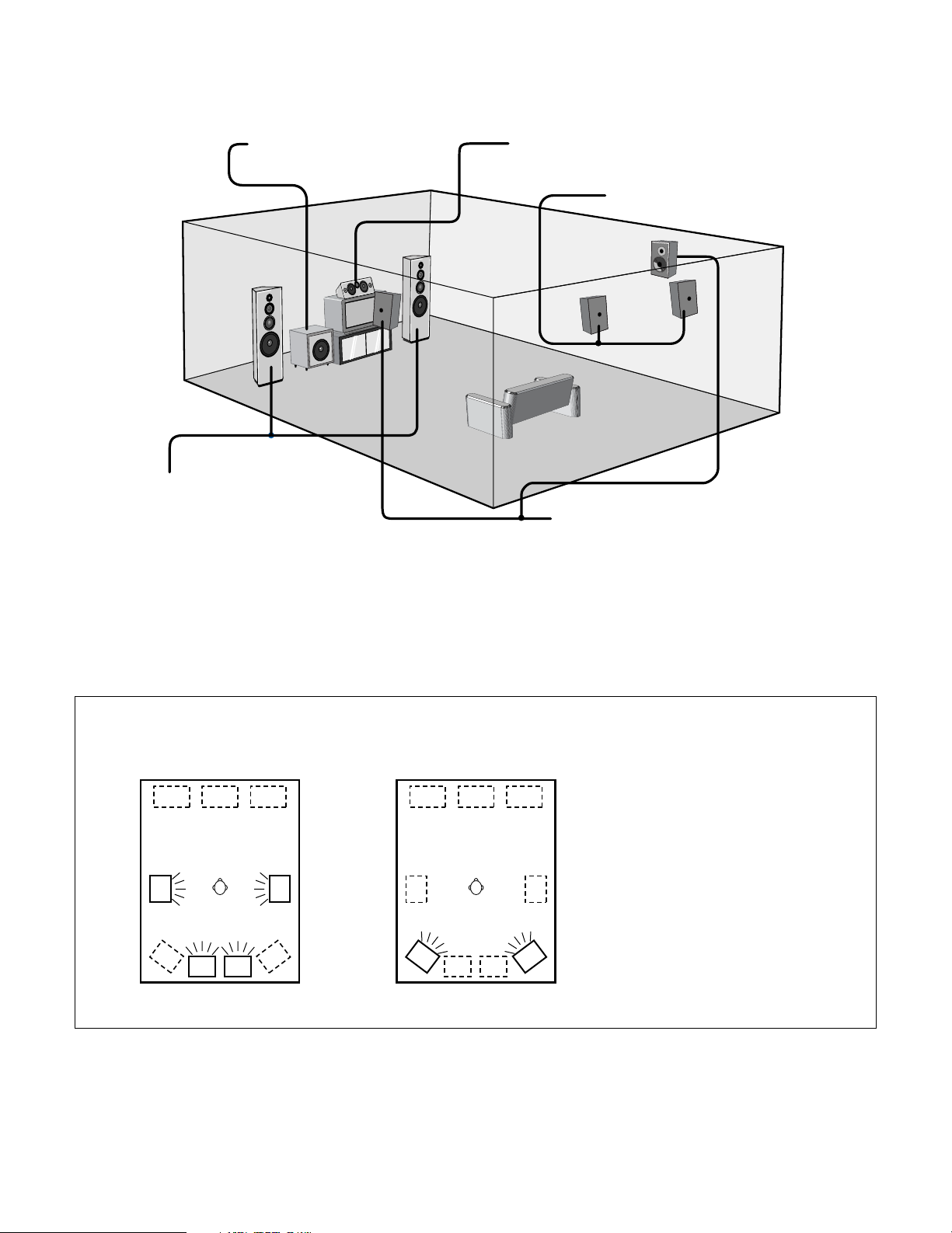
29
2 Speaker system layout
Basic system layout (For a THX Ultra2 system)
• The following is an example of the basic layout for a system consisting of eight speaker systems and a television monitor:
Subwoofer Center speaker system
Surround speaker systems
Surround back speaker systems
Front speaker systems
Set these at the sides of the TV or screen with
their front surfaces as flush with the front of the
screen as possible.
• Surround speaker selector function
This function makes it possible to achieve the optimum sound fields for different sources by switching between two systems of surround
speakers (A and B). The settings of the different speakers (A only, B only or A+B) are stored in the memory for the different surround
modes, so they are set automatically when the surround mode is selected.
AA
BB
AA
BB
SB SB SB SB
Using A only
(Multi surround speaker system)
Using B only
(Single surround speaker system)
(SB: Surround Back Speakers)
Two surround back speakers are required to use the THX Ultra2 Cinema,THX Music mode and THX Games mode.
Set the surround back speakers so that the distance to the listening position is the same for both the left and right speakers. It is also
recommended that the deviations of the distance from the listening position to L and R channel speakers (front left (FL) and front right (FR),
surround left (SL) and surround right (SR), surround back left (SBL) and surround back right (SBR)) is less than 60 cm (2 ft).
With the AVC-A1XV it is also possible to use the surround speaker selector function to choose the best layout for a variety of sources and surround
modes.
Page 30
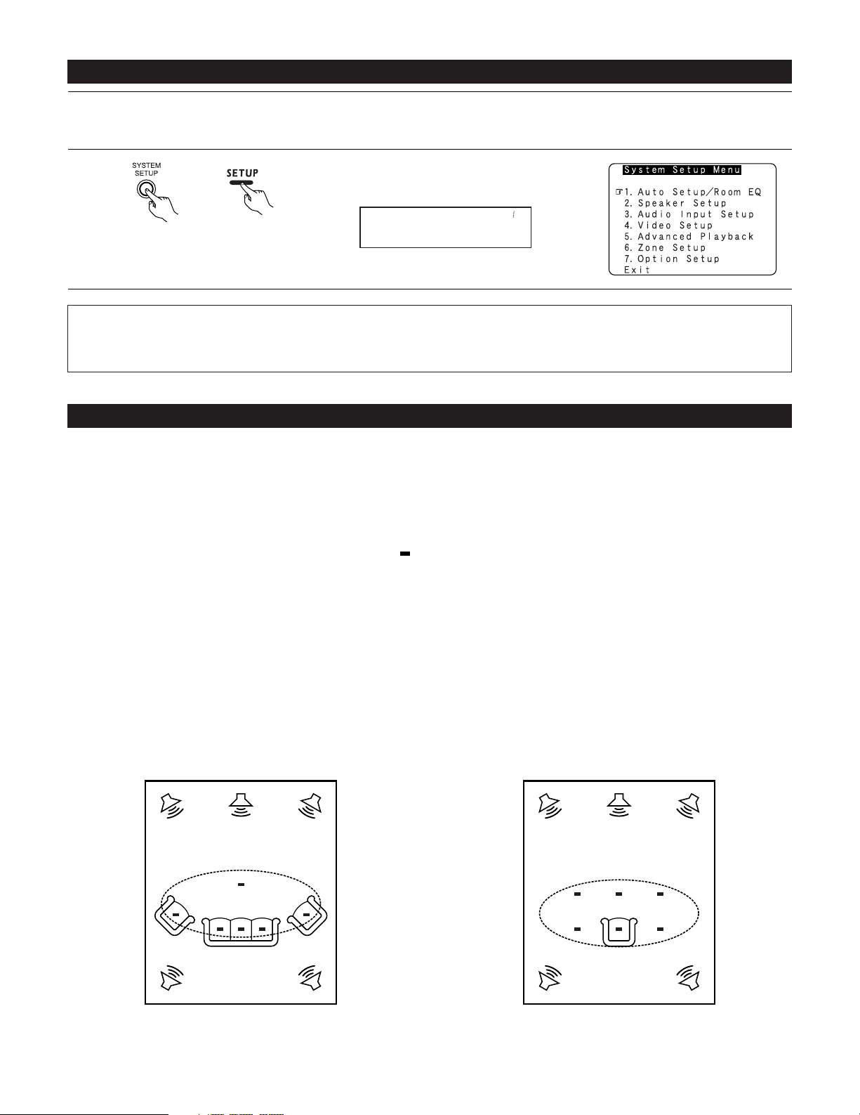
Example w:
*
M
30
Before setting up the system
1
2
Check that all the connections are correct, then turn on the main unit’s power.
Setup will not be possible when the unit is set to Pure Direct ON, the Video Off mode, or when the headphones are plugged in. Therefore,
please cancel the mode or reverse the condition.
Display the System Setup Menu.
(Main unit) (Remote control unit)
Auto Set/RoomEQ
*System Setup
NOTES:
• The System Setup menu composition is of a layered design that includes the related items below the large table title as contained in the
tables of pages 26~28.
• Wherever your position in System Setup, one more press of the System Setup button permits a move to one level higher.
Auto Setup / Room EQ
The Auto Setup and Room EQ function of this unit performs an analysis of the speaker system and measures the acoustic characteristics of your
room to permit an appropriate automatic setting.
The AVC-A1XV’s Audyssey MultEQ XT function has the feature that it provides the optimum listening environment at all listening positions in the
home theater, where there are often multiple listeners viewing programs together. To achieve this, it is first necessary to use a microphone to
measure test tones generated from the different speakers at the various listening positions. All this measured data is analyzed with a unique
method to comprehensively improve acoustic characteristics in the listening area. For optimum effectiveness, measurements should be
performed at six or more points. Move the microphone successively within the listening area surrounded by the speakers as shown on the
diagram below to measure the test tones. When listening to music or viewing movies with the whole family, move the microphone successively
to the different positions in which the members of the family sit (“ ” on the diagram indicates the points of installation) and measure repeatedly
(Example q). Even if the number of people using the home theater is small, taking multiple measurements at or near the listening positions makes
it possible to correct the sound more effectively (Example w).
The AVC-A1XV’s Room EQ function offers three correction curves: “Audyssey”, “Front” and “Flat”. These can be selected after performing the
auto setup procedure. Details of the different correction curves are described below.
Audyssey : This adjusts the frequency response of all speakers to correct the effects of room acoustics.
Front : This adjusts the characteristics of each speaker to the characteristics of the front speakers.
Flat : This the frequency response of all speakers flat.
This is suitable for multi-channel music reproduction, from discrete music sources such as Dolby Digital 5.1, DTS, DVD-Audio and
SACD.
About the main listening position (*M)
The main listening position is the point where a listener sits most often or the listening position when only one person is listening. Measurements
on the AVC-A1XV start from this point. Correction for the speaker distance (“Delay Time”) is set based on this point.
Example q:
*
M
Page 31

31
2 Measurement flow
I. Connect the microphone to be used for the auto setup procedure.
Please place the measuring microphone at ear height at the main listening
position.
III. Preliminary measurement items
q Measuring the background noise (noise in the room)
w Determining whether or not speakers are connected (speaker detection)
e Checking the polarities of the speakers
NOTE:
•A moderately loud test tone is output during
the measurement. Please consider this should
you be planning night time measurements, and
consider not allowing small children into the
listening time.
II. Extra Setup
q Channel Setup
w Power Amp Assign
By default, the speaker system
setting is set to 9.1 channels.
Please set under “Extra Setup”,
only when you want to change
this arrangement.
III. Check the results of the speaker detection.
IV.Speaker system measurement items
q Speaker Configuration : This sets the speaker bass reproduction ability.
w Delay Time : This sets the optimum delay time from each speaker corresponding to the listening position.
e Channel Level : This sets the volume that is output from each speaker.
r Crossover Frequency : This set the frequency (Hz) below which the bass sound of the various speakers is to be output from
the subwoofer.
t Room EQ : This sets the frequency response of each speaker.
(Main (1st) listening position)
Continue measuring ?
Select “OK Next” and put the
microphone at next point.
Quit measuring ?
Select “Calculate”.
V. Check the results of the speaker system measurements.
V. Store the measurement results in the memory.
Move the microphone to the 2nd
to 8th listening positions and
repeat the measurement.
Page 32

32
Before performing the Auto Setup procedure
1
Check again that the speakers are securely connected to the AVC-A1XV.
2
Set the volume to halfway and set the crossover frequency to the maximum or Low pass filter off if your subwoofer can adjust the output
volume and the crossover frequency. Some subwoofers have a standby mode. Be sure to turn this function off before performing the
Auto Setup procedure.
3
The auto setup procedure uses the OSD (on-screen display) function, so connect the AVC-A1XV to a TV, projector, or other monitor.
I
. Connecting the microphone for Auto Setup
1
Connect the microphone for Auto Setup to the Setup Mic connector on the front panel of the unit.
2
Mount the auto setup microphone onto a camera tripod, etc.,
and place it at ear height at the main listening position (*) in
the listening room with the sound receptor facing the ceiling.
When placing the microphone, adjust the height so that the
microphone’s sound receptor is at the height of the ears of
the listener.
Be sure that at the beginning, the measurement is started
with the microphone set up at the main listening position.
NOTE:
• Do not disconnect the microphone until the settings are
completed.
Microphone
Page 33

33
1
Select “Auto Setup / Room EQ” at the System Setup
Menu.
CH SEL
ENTER
(Main unit) (Remote control unit)
Auto Set/RoomEQ
*System Setup
2
Display the Auto Setup / Room EQ menu screen.
CH SEL
ENTER
(Main unit) (Remote control unit)
Auto Setup
*AutoSet/RoomEQ
Setting the Auto Setup / Room EQ
1
1-1. Setting the Auto Setup
1
Select “Auto Setup” at the Auto Setup / Room EQ
menu.
CH SEL
ENTER
(Main unit) (Remote control unit)
Auto Setup
*AutoSet/RoomEQ
2
Display the Auto Setup screen.
CH SEL
ENTER
(Main unit) (Remote control unit)
Start
*Auto Setup
The message “Connect Microphone” is displayed
if no microphone is connected. If so, connect the
auto setup microphone.
Page 34

34
II
. Extra Setup
• By default, the speaker system setting is set to 9.1 channels.
Perform this setting if you want to change the channel setup to match the speaker system you are using or to conduct the power amplifier
assignment procedure. If you do not want to perform this “Extra Setup” procedure, proceed to the “Preliminary measurements” on page 35.
1
Select “Extra Setup”.
CH SEL
ENTER
(Main unit) (Remote control unit)
Extra Setup
*Auto Setup
2
Press the Cursor left button.
Switch to the Extra Setup screen.
CH SEL
ENTER
(Main unit) (Remote control unit)
Channel Setup
*Extra Setup
3
Choose the setting you want to change then press the ENTER button to switch to the setting
screen.
• For instructions on making the “Channel Setup” settings, see pages 92~95.
• For instructions on making the “Power Amp Assign” settings, see pages 96~100.
The speakers measured with this Auto Setup procedure are based on the setting of these
“Channel Setup” and “Power Amp Assign” functions.
(Main unit)
CH SEL
ENTER
(Remote control unit)
CH SEL
ENTER
(Main unit)
(Remote control unit)
4
CH SEL
ENTER
(Main unit) (Remote control unit)
Once the settings are completed, press the ENTER button at the each setting screen.
The Extra Setup menu re-appears.
5
Select “Exit” and press the ENTER button to return to the Auto Setup screen.
Page 35

35
III
. Preliminary measurements
• This procedure is used to automatically determine the background noise, whether or not speakers are connected, and the polarities of the
connected speakers.
1
Select the “Start” and press the Cursor left
button.
Start the preliminary measurements.
Start
*Auto Setup
2
The screen shown at the right appears once the
preliminary measurements are completed.
Press the ENTER button to switch the Speaker
Detect Check screen.
Sp Detect Check
Cautions when making the measurements:
• It is not possible to measure properly if there are any obstacles between the speakers
and microphone. Check that there are no obstacles.
• Please do not stand between or near the speakers and the microphone during the
measurements.
•To avoid affecting the measurements, turn off the air-conditioner or any other device that
makes noise and take the measurements with the room as quiet as possible.
•Measurement is canceled when MASTER VOLUME is operated while the Auto Setup is
performed.
(Main unit)
CH SEL
ENTER
(Remote control unit)
CH SEL
ENTER
(Main unit)
(Remote control unit)
CH SEL
ENTER
(Main unit) (Remote control unit)
3
Check the results of the speaker detection.
Press the ENTER button to switch to the second screen.
If the check ends, press the ENTER button again.
CH SEL
ENTER
(Main unit) (Remote control unit)
[First screen] [Second screen]
NOTE:
• Subsequent measurements will be made based on this data, so be sure to check the results of these measurements.
If the results are not as expected or if an error message is displayed, select “Retry” and perform the measurements again. (For
details on the error messages, see page 39.)
If the results of remeasurement are still not as expected or if an error message is displayed, turn off the power switch and check
the speaker connections. Then start the measurements again from the beginning.
Page 36

36
IV
. Speaker system measurement
•With these measurements, the “Speaker Configuration”, “Delay Time”, “Channel Level”, “Crossover Frequency” and “Room EQ” are analyzed
automatically. The main listening position is measured first, so leave the microphone where it is.
1
Select the “OK Start” and press the Cursor left
button.
Measurements for the first point start.
OK Start
Main Position
NOTE:
•With these measurements, test tones are not output from channels to which speakers
have been judged not to be connected in the preliminary measurements. Do not change
the connection of speakers or the subwoofer’s volume after performing the preparation
measurements and before performing these measurements.
(Main unit)
CH SEL
ENTER
(Remote control unit)
CH SEL
ENTER
(Main unit)
(Remote control unit)
2
q The screen shown at the right appears once the measurements for the main listening
position are completed.
Next the measurements for the second point will be taken. Place the microphone at the
second listening position. For instructions on the position in which the microphone should
be placed, see page 30. (When making the measurements, be sure to position the
microphone at the approximate ear height of the seated listener(s).)
(Main unit)
CH SEL
ENTER
(Remote control unit)
CH SEL
ENTER
(Main unit)
(Remote control unit)
w Select the “OK Next” and press the Cursor left
button.
Measurements for the second point start.
OK Next
2nd Position
3
Perform step 2 repeatedly.
The more measurement points, the better the resulting room correction effect. We recommend a minimum of 6 measurement points –
8 measurement points provides the best room correction effect.
Page 37

37
5
Once the calculations are completed, a screen for confirming the results of the measurements appears.
4
After measuring at the number of points according
to your listening environment, select “Calculate”
and press the Cursor left button.
The speaker system is analyzed.
(Main unit)
CH SEL
ENTER
(Remote control unit)
CH SEL
ENTER
(Main unit)
(Remote control unit)
Calculate
7th Position
The amount of time required for the analysis
depends on the number of speakers and the
number of measuring points. The greater the
number of speakers and measuring points, the
longer the time required. For example, for 9.1channel systems and 6 measuring points, the
calculations require approximately 5 minutes.
Measurements can be ended when there are 5
or more measurement locations; however, to
obtain better results, measurements at 6 or
more locations is recommended.
Page 38

38
V
. Check of the measurement result
• The results of the measured items can be checked.
For instructions on checking the equalizer parameters, see pages 43~45.
1
Select the items.
The measurement results of each item can be
checked here.
Sp Config.Check
*Auto Setup
CH SEL
ENTER
(Main unit) (Remote control unit)
2
Press the ENTER button and display the verification screen.
Press the ENTER button to switch to the second screen.
CH SEL
ENTER
(Main unit) (Remote control unit)
[Delay Time Check]
NOTE:
• When measurements have been made using the measurement microphone, speakers
with a built-in filter such as subwoofers might be set with a value that differs from the
physical distance because of the internal electrical delay.
[Channel Level Check][Speaker Config. Check]
3
If the check ends, press the ENTER button again.
CH SEL
ENTER
(Main unit) (Remote control unit)
4
Select whether or not to save the data you have
checked.
Select the following items based on the
measurement results.
Store : Set with the checked measurement value.
Cancel : If you do not want to set the contents
you have checked, cancel the auto setup
settings.
Store
*Auto Setup
CH SEL
ENTER
(Main unit) (Remote control unit)
[Crossover Freq. Check]
Page 39

39
CH SEL
ENTER
(Main unit) (Remote control unit)
5
When “Store” is selected, all parameters are stored
up.
After the data is stored, the “Auto Setup / Room EQ”
menu screen appears automatically.
NOTE:
• Do not turn off the power while the data is
being stored. If the power is turned off while
the data is being stored, the Room EQ
parameters stored in the memory will be
cleared, and it will not be possible to select the
“Audyssey”, “Front” or “Flat” equalizer
settings.
About the error message
• These error messages will be displayed when performing the measurements of Auto Setup and the automatic measurements can not be
completed because of the speaker arrangement, measurement environment, or other factors. Please check the following matters, reset the
pertinent items, and measure again. Be sure to turn off the AVC-A1XV’s power before checking the speaker connections.
Screen example Cause Measures
• The speakers required for producing suitable
reproduction have not been detected.
q The front L and front R speakers were not properly
detected.
w Only one channel of the surround (A) and surround
(B) speakers was detected.
e Sound was output from the R channel when only
one surround back speaker was connected.
r The surround back or the surround (B) speaker
was detected, but the surround (A) speaker was
not detected.
If multiple errors occur, use the cursor left and right
buttons to check the contents.
• Check that the pertinent speakers are
properly connected.
• The speaker polarity is connected in reverse.
If multiple errors occur, use the cursor left and right
buttons to check the contents.
• Check the polarity of the pertinent
speakers.
• For some speakers, the screen below
may be displayed even though the
speakers are properly connected.
If so, select “Skip0”.
• There is too much ambient noise in the room and the
measurements cannot be made accurately.
• Either turn off the power of the
device that generated the noise
during the measurements or move
the device away.
•Try again at a time when it is quieter.
• The measurement microphone is not connected, or
all of speakers have not been detected.
• Connect the measurement microphone
to the microphone connector.
• Check the speaker connection.
Page 40

40
1
Select “Room EQ Setup” at the Auto Setup / Room
EQ menu.
CH SEL
ENTER
(Main unit) (Remote control unit)
Room EQ Setup
*AutoSet/RoomEQ
• Select the setting of an Equalizer that has been set with Auto Setup or Manual EQ.
2
q When the “All” is selected and press the ENTER
button, display the Select the EQ Curve screen.
Select the Equalizer setting.
OFF : The Equalizer is not used.
Audyssey : Adjusts the frequency response of
all speakers to correct the effects of
room acoustics.
Front : Adjusts the frequency response of
the surround speakers to match the
characteristics of the front channel
speakers.
Flat : Adjusts the frequency response of
all speakers to the flattest response.
This mode is suitable for multi-channel
music surround sound sources.
Manual : Selects the setting value that was set in the Manual EQ setup.
For details of the “5-4. Manual EQ Setup”, see pages 77~79.
(Main unit) (Remote control unit)
Display the Room EQ Setup screen.
CH SEL
ENTER
(Main unit) (Remote control unit)
SurMode: ALL
*Room EQ Setup
3
Select All or Assign.
All : Sets the Equalizer for all surround modes.
Assign : Sets the Equalizer individually for each surround mode.
CH SEL
ENTER
(Main unit) (Remote control unit)
4
EQ : Audyssey
*Room EQ Setup
OFF Audyssey
FlatManual
Front
NOTES:
• The Equalizer setting of “Audyssey”, “Flat” and “Front” can be selected after performing the Auto Setup.
• When the speaker set as “None” with the Auto Setup is changed to on manually, the equalizer of “Audyssey”, “Front” and “Flat”
cannot be used.
• The Equalizer setting can be selected directly by ROOM EQ button on the Main unit or Remote control unit.
• When headphones are connected, the Room EQ cannot be used.
w If “Assign” is selected, select the desired equalizer setting using the ROOM EQ buttons on
the Main unit or Remote control unit. Equalizer settings for the individual surround modes can
be stored in the memory.
1-2. Setting the Room EQ Setup
CH SEL
ENTER
(Main unit) (Remote control unit)
Whenever the ROOM EQ button on Main unit or
Remote control unit is pressed, the display
switches as shown below.
Page 41

41
1-3. Setting the Direct Mode
1
Select “Direct Mode Setup” at the Auto Setup /
Room EQ menu.
CH SEL
ENTER
(Main unit) (Remote control unit)
Direct Mode
*AutoSet/RoomEQ
• Perform the ON/OFF setting of Room EQ when the surround mode is Direct or Pure Direct.
2
Display the Direct Mode Setup screen.
CH SEL
ENTER
(Main unit) (Remote control unit)
3
Select ON or OFF.
CH SEL
ENTER
(Main unit) (Remote control unit)
4
Enter the setting .
The Auto Setup / Room EQ menu reappears.
CH SEL
ENTER
(Main unit) (Remote control unit)
Room EQ: OFF
*Direct Mode
5
Enter the setting.
The Auto Setup / Room EQ menu reappears.
CH SEL
ENTER
(Main unit) (Remote control unit)
Page 42

42
4
Enter the setting.
The Auto Setup / Room EQ menu reappears.
CH SEL
ENTER
(Main unit) (Remote control unit)
3
Select the Mic input jack or V.AUX L jack.
CH SEL
ENTER
(Main unit) (Remote control unit)
1-4. Setting the MIC Input Select
1
Select “Mic Input Select” at the Auto Setup / Room
EQ menu.
CH SEL
ENTER
(Main unit) (Remote control unit)
Mic In Select
*AutoSet/RoomEQ
• Sets whether the setup microphone is connected to the PIN JACK (V.AUX L channel) connector or the MINI JACK (SETUP MIC) connector.
• Use this setting when using a microphone other than the included one for measurements when performing the auto setup procedure.
• The microphone included with the AVC-A1XV is a measurement microphone designed specifically for use during the auto setup procedure.
Select “Mic” and connect the included microphone to the “SETUP MIC” mini-jack. When conducting the auto setup procedure using a separate
high performance condenser microphone for measurements, select “V.AUX L” and connect the microphone to the “V.AUX Lch” pin jack.
Please ask the DENON Authorized Service Center about the usable microphone other than the included one.
2
Display the Mic Input Select screen.
CH SEL
ENTER
(Main unit) (Remote control unit)
Mic
*Mic In Select
Page 43

43
1-5. Check the Parameter
1
Select “Parameter Check” at the Auto Setup / Room
EQ menu.
CH SEL
ENTER
(Main unit) (Remote control unit)
• The results of the measured items can be checked.
• The EQ parameters that were set in Auto Setup can be checked.
• This item is automatically displayed, after the measurement result of the “Auto Setup / Room EQ” is decided.
2
Display the Parameter Check screen.
CH SEL
ENTER
(Main unit) (Remote control unit)
Parameter Check
*AutoSet/RoomEQ
Sp Config.Check
*ParameterCheck
3
Select the items.
CH SEL
ENTER
(Main unit) (Remote control unit)
4
Press the ENTER button and display the verification screen.
For instructions on checking the results of each item, see page 38.
CH SEL
ENTER
(Main unit) (Remote control unit)
5
EQ parameters can be checked here.
Select “EQ Parameter Check” at the Parameter
Check screen.
CH SEL
ENTER
(Main unit) (Remote control unit)
6
Display the EQ Parameter Check screen.
CH SEL
ENTER
(Main unit) (Remote control unit)
EQ Check
*ParameterCheck
Audyssey
*EQ Check
7
Select the Equalizer curve.
CH SEL
ENTER
(Main unit) (Remote control unit)
Page 44

44
8
Display the parameter screen.
The display is only an approximate picture of the
response and that correction is happening at all
frequencies.
9
CH SEL
ENTER
(Main unit) (Remote control unit)
Select the speaker channel.
CH SEL
ENTER
(Main unit) (Remote control unit)
FL/FR :Next
EQ Chk Audyssey
10
If the check ends, select “Exit” and press the ENTER
button.
The EQ Parameter Check screen reappears.
Exit
EQ Chk Audyssey
11
Select “Exit” and press the ENTER button at the EQ
Parameter Check screen.
The Parameter Check screen reappears.
Exit
*EQ Check
(Main unit)
CH SEL
ENTER
(Remote control unit)
CH SEL
ENTER
(Main unit)
(Remote control unit)
12
The results of the “Auto Setup” procedure can be
reset even if the settings have been changed after
performing the “Auto Setup” procedure.
Select “Restore Yes 0” then press the Cursor left
button.
Restore
*ParameterCheck
(Main unit)
CH SEL
ENTER
(Remote control unit)
CH SEL
ENTER
(Main unit)
(Remote control unit)
(Main unit)
CH SEL
ENTER
(Remote control unit)
CH SEL
ENTER
(Main unit)
(Remote control unit)
Page 45

45
13
Select “Exit” and press the ENTER button at the
Parameter Check screen.
The Auto Setup / Room EQ menu reappears.
Exit
*ParameterCheck
(Main unit)
CH SEL
ENTER
(Remote control unit)
CH SEL
ENTER
(Main unit)
(Remote control unit)
Setting the Speaker Setup
1
2
Select “Speaker Setup” at the System Setup Menu.
Display the Speaker Setup menu screen.
Speaker Setup
*System Setup
CH SEL
ENTER
(Main unit) (Remote control unit)
CH SEL
ENTER
(Main unit) (Remote control unit)
2
• If the “Auto Setup” procedure has already been performed, there is no need to make this setting.
• Perform this setting if you wish to make the settings for your speaker systems manually.
Speaker Config.
*Speaker Setup
Select “Exit” and press the ENTER button at the
Auto Setup / Room EQ menu screen.
The System Setup Menu reappears.
Exit
*AutoSet/RoomEQ
14
(Main unit)
CH SEL
ENTER
(Remote control unit)
CH SEL
ENTER
(Main unit)
(Remote control unit)
Page 46

46
2-1. Setting the type of speakers
• The composition of the signals output to each channels and the frequency response are adjusted automatically according to the combination of
speakers actually being used.
1
CH SEL
ENTER
Select “Speaker Config.” at the Speaker Setup
menu.
2
CH SEL
ENTER
Display the Speaker Config. screen.
(Main unit) (Remote control unit)
Speaker Config.
*Speaker Setup
(Main unit) (Remote control unit)
4
ENTER the setting.
The Speaker Setup menu reappears.
NOTE:
• Select “Large” or “Small” not according to the actual size of the speaker but according to the speaker’s capacity for playing low frequency
(bass sound below the frequency set for the Crossover Frequency) signals. If you do not know, try comparing the sound at both settings
(setting the volume to a level low enough so as not to damage the speakers) to determine the proper setting.
CH SEL
ENTER
(Main unit) (Remote control unit)
3
Set whether speakers are connected or not and, if so, their size parameters.
q Select the speaker.
w Select the parameter.
Center Sp.
Front Sp.
Subwoofer
Surround Sp. A
Surround back Sp.
Surround Sp. B
CH SEL
ENTER
(Main unit) (Remote control unit)
CH SEL
ENTER
(Main unit) (Remote control unit)
Front : Small
*Speaker Config
Page 47

47
• Parameters
Large.....................Select this when using speakers that can fully reproduce deep bass well below 80 Hz.
Small ....................Select this when using speakers that are not capable of handling deep bass well below 80 Hz. Most home theater main and
surround speakers perform best when configured as SMALL. Deep bass content in any channel with a SMALL speaker is
routed to the subwoofer(s).
None.....................Select this when no speakers are installed.
Yes/No..................Select “Yes” when a subwoofer is installed, “No” when a subwoofer is not installed.
2 spkrs/1 spkr......Select the number of speakers to be used for the surround back channel.
A subwoofer with sufficient low frequency playback capability can better handle deep bass than most main and surround speakers, and the
system’s overall performance will be greatly enhanced when SMALL is set for the main (front) and surround speakers.
To take full advantage of the performance of the Home THX certified speaker systems, set the front, center and surround speaker size
parameters to “Small” and the subwoofer to “Yes”.
For the majority of speaker system configurations, using the SMALL setting for all main and surround speakers and connected subwoofer(s)
set to ON will yield the best results.
When “Front” is set to “Small”, “Subwoofer” is automatically set to “Yes”, and when “Subwoofer” is set to “No”, “Front” is automatically
set to “Large”.
2-2. Setting the low frequency distribution
• Set the subwoofer mode according to the speaker system being used.
• Select the play mode that provides bass reproduction with body.
4
Enter the setting.
The Speaker Setup menu reappears.
1
Select “Subwoofer Setup” at the Speaker Setup
menu.
Select the setting.
CH SEL
ENTER
(Main unit) (Remote control unit)
CH SEL
ENTER
(Main unit) (Remote control unit)
Subwoofer Setup
*Speaker Setup
CH SEL
ENTER
(Main unit) (Remote control unit)
3
Mode: LFE-THX-
*SubwooferSetup
2
Display the Subwoofer Setup screen.
CH SEL
ENTER
(Main unit) (Remote control unit)
LFE–THX– : For any channel(s) that are set to LARGE, low frequencies in that channel’s
corresponding source are directed to that loudspeaker only. Low frequencies
that are directed to the subwoofer(s) are from the program source LFE channel,
and from other channels where the speakers are set to SMALL. THX is
recommended in this play mode so that bass interference is less likely to occur
in the room.
LFE+Main : Low frequencies from speaker channels that have been set to LARGE are
reproduced from those speakers as well as from the subwoofer(s). Depending
upon the characteristics of the LARGE main speakers, this mode may provide a
more even low frequency response throughout the listening room.
Page 48

48
NOTES:
— Assignment of low frequency signal range (2-1) —
• The only signals produced from the subwoofer channel are LFE signals (during playback of Dolby Digital or DTS signals) and the low
frequency signal range of channels set to “Small” in the setup menu. The low frequency signal range of channels set to “Large” are
produced from those channels.
— Subwoofer Setup (2-2) —
• The subwoofer mode setting is only valid when and “Yes” is set for the subwoofer in the “2-1. Speaker Configuration” settings (see
pages 46, 47).
• When the input signal is analog or a PCM signal not including LFE signals, if “LFE-THX-” is selected, the low frequency component is not
output from the subwoofer. To output the subwoofer channel, select “LFE+Main”.
2-3. Setting the Delay Time
1
Select “Delay Time” at the Speaker Setup menu.
2
3
Display the Delay Time screen.
Select the desired unit, meters or feet.
Example: When “Meters” is selected
CH SEL
ENTER
(Main unit) (Remote control unit)
CH SEL
ENTER
(Main unit) (Remote control unit)
CH SEL
ENTER
(Main unit) (Remote control unit)
Delay Time
*Speaker Setup
Meters : Feet
*Delay Time
• Input the distance between the listening position and the different speakers to set the delay time for the surround mode.
•Two surround back speakers are required to use the THX Ultra2 Cinema, THX Music modes and THX Games mode.
Set the surround back speakers so that the distance to the listening position is the same for both the left and right speakers.
It is also recommended that the deviations of the distance from the listening position to L and R channel speakers (front left (FL) and front right
(FR), surround left (SL) and surround right (SR), surround back left (SBL) and surround back right (SBR)) is less than 60 cm (2 ft).
Preparations:
Measure the distances between the listening position and the speakers (L1 to L6 on the diagram at
the right).
L1: Distance between center speaker and listening position
L2: Distance between front speakers and listening position
L3: Distance between surround speakers and listening position
L4: Distance between surround back speakers and listening position
L5: Distance between subwoofer and listening position
L6: Distance between surround back L and surround back R
L1
L2
L5
L3
L6
L4
Center FRFL
Subwoofer
SL
Listening position
SR
SBRSBL
Page 49

49
4
5
Once “Meters” or “Feet” is selected in step 3, the
Delay Time screen appears automatically.
Select the speaker to be set.
The picture of the speaker selected blinks.
CH SEL
ENTER
(Main unit) (Remote control unit)
FL : 3.60m
*Delay Time
6
Set the distance between the center speaker and listening position.
The distance changes in units of 0.03 meters (0.1 foot) or 0.3 meters (1 foot) each time the
button is pressed. Select the value closest to the measured distance.
If “Yes” is selected for “Default”, the settings are automatically reset to the default values.
When “Step” is selected, you can select the unit of “0.1 m (1 ft)” or “0.01 m (0.1 ft)”.
Please note that the difference of distance for every speaker should be 6.0 m (20 ft) or less. If
you set an invalid distance, a CAUTION notice, such as screen right will appear. In this case,
please relocate the blinking speaker(s) so that its distance is no larger than the value shown in
highlighted line.
Example: When the distance is set to 3.6 m
for the center speaker
7
Enter the setting.
The Speaker Setup menu reappears.
The AVC-A1XV automatically sets the optimum
surround delay time for the listening room.
CH SEL
ENTER
(Main unit) (Remote control unit)
CH SEL
ENTER
(Main unit) (Remote control unit)
Page 50

Auto :
Adjust the level while listening to the test tones
produced automatically from each speaker.
Manual :
Select the speaker from which you want to produce
the test tone to adjust the level.
50
3
Select the mode.
Select “Auto” or “Manual”.
Example: When the “Auto” mode is selected
4
5
Select “Test Tone Start”.
Select “Yes”.
Tone Start:Yes
*Channel Level
CH SEL
ENTER
(Main unit) (Remote control unit)
T.Tone: Auto
*Channel Level
2-4. Setting the Channel Level
• Use this setting to adjust so that the playback level between the different channels is equal.
•From the listening position, listen to the test tones produced from the speakers to adjust the level.
• The level can also be adjusted directly from the Remote control unit. (For details, see pages 129, 130.)
• The level of each channel should be adjusted to 75 dB (C-weighted, slow meter mode) on a sound level meter at the listening position.
If a sound level meter is not available adjust the channels by ear so the sound levels are the same. Because adjusting the subwoofer level test
tone by ear is difficult, use a well known music selection and adjust for natural balance.
1
2
Select “Channel Level” at the Speaker Setup menu.
Display the Channel Level screen.
Channel Level
*Speaker Setup
T.Tone: Auto
*Channel Level
CH SEL
ENTER
(Main unit) (Remote control unit)
CH SEL
ENTER
(Main unit) (Remote control unit)
CH SEL
ENTER
(Main unit) (Remote control unit)
CH SEL
ENTER
(Main unit) (Remote control unit)
Page 51

51
7
Enter the setting.
The Channel Level screen reappears.
To cancel the settings, press the Cursor down button to select “Level Clear” and “Yes” on the
Channel Level screen, then make the settings again.
NOTES:
• When adjusting the level of an active subwoofer system, you may also need to adjust the subwoofer’s own volume control.
• When you adjust the channel levels while in the SYSTEM SETUP CHANNEL LEVEL mode, the channel level adjustments made will affect
all surround modes. Consider this mode a Master Channel Level adjustment mode.
• After you have completed the SYSTEM SETUP CHANNEL LEVEL adjustments, you can then activate the individual surround modes and
adjust channel levels that will be remembered for each of those modes. Then, whenever you activate a particular surround sound mode,
your preferred channel level adjustments for just that mode will be recalled. Check the instructions for adjusting channel levels within
each surround mode. (See pages 129, 130)
•You can adjust the channel levels for each of the following surround modes: PURE DIRECT/DIRECT, STEREO, DOLBY/DTS SURROUND,
HOME THX CINEMA, 9CH STEREO, WIDE SCREEN, SUPER STADIUM, ROCK ARENA, JAZZ CLUB, CLASSIC CONCERT, MONO
MOVIE, VIDEO GAME and MATRIX.
• When using either surround speakers A or B, or when using surround speakers A and B at the same time, be sure to adjust the balance
of playback levels between each channel for the various selections of “A or B” and “A and B”.
6
a. When “Auto” mode is selected:
Test tones are automatically emitted from each speaker.
The test tones are emitted from each speaker in the following order,
at 4-second intervals the first time and second time around, 2second intervals the third time around and on:
Use the Cursor left and right buttons to adjust all the speakers to the
same volume.
The volume can be adjusted between –12 dB and +12 dB in units of 0.5
dB.
b. When “Manual” mode is selected:
Example: When the volume is set to –11.5 dB
while the test tone is being
produced from the Front Lch
speaker
FL
SW
1spkr
2spkrs
C
FR
SRA
SBL
SLB
SLA
SB
SRB
SBR
When the surround back speaker setting is set to “1spkr” for “2-1.
Speaker Configuration”, this is set to “SB”.
FL : -11.5dB
TestTone Auto
q Select the speaker. w Adjust all the speakers to the same
volume.
Example: “Manual” mode is selected.
FL : -11.5dB
TestTone Manual
CH SEL
ENTER
(Main unit)
(Remote control unit)
CH SEL
ENTER
(Main unit) (Remote control unit)
CH SEL
ENTER
(Main unit) (Remote control unit)
CH SEL
ENTER
(Main unit) (Remote control unit)
Flashing
Flashing
Page 52

52
2-5. Setting the Crossover Frequency
1
Select the “Crossover Frequency” at the Speaker
Setup menu.
• Set the crossover frequency according to the low frequency response characteristics of the various (front, center, surround and surround back)
speaker systems.
• If a connected main or surround loudspeaker has a specified –3 dB low frequency response rolloff, adjust the crossover frequency for that
speaker to match the specified low frequency response limit – e.g. 80 Hz.
• When a speaker is set to SMALL, low frequencies in that channel that are below the crossover frequency are directed to the system’s
subwoofer(s), or to speakers that are set to LARGE, for systems with no connected subwoofer(s).
Select the frequency.
Crossover Freq.
*Speaker Setup
4
Enter the setting.
The Speaker Setup menu reappears.
3
2
Display the Crossover Frequency screen.
Fixed -THX-
*Crossover Freq
FIXED –THX– :
Set to the THX rated 80 Hz crossover frequency.
VARIABLE 40, 60, 80, 90, 100, 110, 120, 150, 200, 250 Hz :
Set as desired according to your speakers’ bass playback ability.
Advanced :
The crossover frequency can be set individually for the different speakers. (See page 53)
If “LFE+Main” is set at “2-2. Subwoofer Setup”, “SW:LFE+Main” (see pages 47, 48) is displayed
at the top right of the screen.
NOTES:
• The crossover frequency is set to 80 Hz in the HOME THX CINEMA mode.
•We recommend using with the crossover frequency set to “FIXED –THX–”, but depending on the speaker, setting it to a different
frequency may improve frequency response near the crossover frequency.
• The crossover frequency mode is valid only when subwoofer is set to ON, and when one or more speakers are set to SMALL, as
described in section “2-1. Speaker Configuration” settings.
CH SEL
ENTER
(Main unit) (Remote control unit)
CH SEL
ENTER
(Main unit) (Remote control unit)
CH SEL
ENTER
(Main unit) (Remote control unit)
CH SEL
ENTER
(Main unit) (Remote control unit)
Page 53

53
2 Setting the crossover frequency individually for the different channels
1
Select “Advanced” at the Crossover Frequency
screen.
Advanced
*Crossover Freq
2
Select the speaker to be set.
Front : 80Hz
*Crossover Freq
3
Select the frequency.
Front : 100Hz
*Crossover Freq
NOTES:
• If “LFE–THX–” is selected at “2-2. Subwoofer Setup”, the frequencies can only be selected
for speakers set to “Small” at “2-1. Speaker Configuration”.
• If “LFE+Main” is set at “2-2. Subwoofer Setup”, the frequencies can be selected regardless of the speaker size setting.
CH SEL
ENTER
(Main unit) (Remote control unit)
CH SEL
ENTER
(Main unit) (Remote control unit)
CH SEL
ENTER
(Main unit) (Remote control unit)
Page 54

54
4
Enter the setting.
The Speaker Setup menu reappears.
For the “WIDE SCREEN” and “9CH STEREO” DSP simulation modes, the surround speakers can be set separately.
See pages 59, 60 for setting the surround speaker when the “Analog” mode is selected at “3-2. EXT.IN Setup”.
2-6. Selecting the Surround Speakers for the different surround modes
• This menu is displayed when both surround speakers A and B are used.
• At this screen preset the surround speakers to be used in each surround modes.
3
q To select the surround mode
w To select the surround speaker
A:When surround speakers A is used.
B:When surround speakers B is used.
A+B : When both surround speakers A and B are used.
CINEMA : A
*Surr Sp Setup
1
Select “Surround Sp Setup” at the Speaker Setup
menu.
Surr Sp Setup
*Speaker Setup
2
Display the Surround Sp Setup screen.
CH SEL
ENTER
(Main unit) (Remote control unit)
CH SEL
ENTER
(Main unit) (Remote control unit)
CH SEL
ENTER
(Main unit) (Remote control unit)
CH SEL
ENTER
(Main unit) (Remote control unit)
CH SEL
ENTER
(Main unit) (Remote control unit)
Page 55

55
5
Press the ENTER button to return to the THX Audio Setup screen.
2-7. Setting the THX Audio Setup
[1] Settings for using a THX Ultra2 compatible subwoofer
• Make these settings when “Yes” is selected for the subwoofer in the “2-1. Speaker Configuration” settings.
There is not displayed when “No” selected. (pages 46, 47)
4
When using a THX Ultra2 compatible subwoofer or
subwoofer that frequency response extends to 20
Hz, select “Yes”. Otherwise select “No”.
• When “Yes” is selected
“Boundary Gain Compensation” can be selected
and the compensation set to “OFF”.
• If the bass sound seems too strong
Set “Boundary Gain Compensation” to “ON”. This
activates a filter that gently reduces very deep
bass below 55 Hz to provide the flattest overall
deep bass response. Select ON or OFF according
to how strong you prefer the deep bass response
to be.
Boundary Gain
*THX AudioSetup
1
Select “THX Audio Setup” at the Speaker Setup
menu.
THX Audio Setup
*Speaker Setup
2
Display the THX Audio Setup screen.
3
Select “Boundary Gain Compensation”, then press the
ENTER button.
(Main unit)
CH SEL
ENTER
(Remote control unit)
CH SEL
ENTER
(Main unit)
(Remote control unit)
THX U2 SW: Yes
Boundary Gain
CH SEL
ENTER
(Main unit) (Remote control unit)
CH SEL
ENTER
(Main unit) (Remote control unit)
CH SEL
ENTER
(Main unit) (Remote control unit)
(Main unit)
CH SEL
ENTER
(Remote control unit)
CH SEL
ENTER
(Main unit)
(Remote control unit)
CH SEL
ENTER
(Main unit) (Remote control unit)
THX U2 SW: No
Boundary Gain
Page 56

56
[2] Surround Back Speaker Position Settings
• When two surround back speakers have been set in “2-1. Speaker Configuration” (pages 46, 47), set the distance of the speakers. There
is not displayed when “1spkr” selected.
• This setting is necessary to achieve the optimum effect in the THX Surround EX, THX Ultra2 Cinema, THX Music modes and THX Games
mode. It is recommended that SBL/SBR speakers are placed together as close as possible.
0m to 0.3m
SB Sp Position
1
Select “Surround Back Speaker Position” at the THX
Audio Setup screen and press the ENTER button.
SB Sp Position
*THX AudioSetup
2
Select the settings according to the distances of the
two surround back speakers. (page 48)
(Main unit)
CH SEL
ENTER
(Remote control unit)
CH SEL
ENTER
(Main unit)
(Remote control unit)
Exit
*THX AudioSetup
3
Press the ENTER button to return to the THX Audio Setup screen.
4
Select “Exit” and press the ENTER button to return
to the Speaker Setup menu screen.
Exit
*Speaker Setup
5
Select “Exit” and press the ENTER button at the
Speaker Setup menu screen.
The System Setup Menu reappears.
CH SEL
ENTER
(Main unit) (Remote control unit)
CH SEL
ENTER
(Main unit) (Remote control unit)
(Main unit)
CH SEL
ENTER
(Remote control unit)
CH SEL
ENTER
(Main unit)
(Remote control unit)
(Main unit)
CH SEL
ENTER
(Remote control unit)
CH SEL
ENTER
(Main unit)
(Remote control unit)
Page 57

57
Setting the Audio Input Setup
1
2
Select “Audio Input Setup” at the System Setup
Menu.
Display the Audio Input Setup menu screen.
Audio In Setup
*System Setup
3
• Make the audio-related settings.
3-1. Setting the Digital In Assignment
• This setting assigns the digital input jacks of the AVC-A1XV for the different input sources.
1
2
3
Select “Digital In Assign” at the Audio Input Setup
menu.
Display the Digital In Assign screen.
Select the digital input jack to be assigned to the input source.
q Select the input source.
Digital In
*Audio In Setup
CD : COAX1
*Digital In
w Select the digital input jack.
Select from among COAX 1 to 6, OPT 1 to 6.
Select “OFF” for input sources for which no digital input jacks are used.
It is not possible to select the same digital input jack for different input sources.
If the same digital input jack is selected, the setting for the input source that was previously
assigned switches to “OFF”.
The HDMI input terminal is displayed when it is assigned to the input source at “4-5.
HDMI/DVI In Assign”. (See pages 70, 71)
If “Yes” is selected for “Default”, the settings are automatically reset to the default
values.
CH SEL
ENTER
(Main unit) (Remote control unit)
CH SEL
ENTER
(Main unit) (Remote control unit)
CH SEL
ENTER
(Main unit) (Remote control unit)
CH SEL
ENTER
(Main unit) (Remote control unit)
CH SEL
ENTER
(Main unit) (Remote control unit)
CH SEL
ENTER
(Main unit) (Remote control unit)
Digital In
*Audio In Setup
Page 58

58
4
Enter the setting.
The Audio Input Setup menu reappears.
NOTES:
• The OPTICAL 3, 4 and 5 jacks on the AVC-A1XV’s rear panel are equipped with an optical digital output jack for recording digital audio
signals to a CD recorder, MD recorder, or other digital audio recording deck. Use this for digital recording between a digital audio source
(stereo - 2 channel) and a digital audio recorder.
• Do not connect the output of the component connected to the OPTICAL 3 OUT jack on the AVC-A1XV’s rear panel to any jack other than
the OPTICAL 3 IN jack.
• Do not connect the output of the component connected to the OPTICAL 4 OUT jack on the AVC-A1XV’s rear panel to any jack other than
the OPTICAL 4 IN jack.
• Do not connect the output of the component connected to the OPTICAL 5 OUT jack on the AVC-A1XV’s rear panel to any jack other than
the OPTICAL 5 IN jack.
• “PHONO” cannot be selected on the Digital In Assignment screen.
Refer to “DENON LINK connections”. (See page 18)
CH SEL
ENTER
(Main unit) (Remote control unit)
Page 59

59
3-2. Setting the EXT. IN Setup
• Set the method of playback of the analog input signal connected to the EXT.IN-1 (10 CH) and EXT.IN-2 (6 CH) terminal.
1
Select “EXT.IN Setup” at the Audio Input Setup
menu.
2
Display the EXT.IN Setup screen.
3
q Select the input terminal. w Switch to the setting screen.
4
Select the item to be set (use the Cursor button
to the up and down) then select the parameter
(use the Cursor left and right buttons).
EXT.IN Setup
*Audio In Setup
EXT.IN-1
*EXT.IN Setup
Mode : DSP
*EXT.IN-1 Setup
CH SEL
ENTER
(Main unit) (Remote control unit)
CH SEL
ENTER
(Main unit) (Remote control unit)
CH SEL
ENTER
(Main unit) (Remote control unit)
CH SEL
ENTER
(Main unit) (Remote control unit)
(Main unit)
CH SEL
ENTER
(Remote control unit)
CH SEL
ENTER
(Main unit)
(Remote control unit)
Page 60

60
MODE :
DSP : The analog input signal is converted into a digital signal and undergoes DSP processing.
System Setup settings (speaker configuration, channel delay, etc.) are reflected in the same way as for other input signals.
The surround playback mode button functions.
ANALOG : The analog input signal is played without DSP processing.
SW and center channel: Down-mixing is conducted by the analog circuit. Surround and surround back channels: Not
output if “No” is selected at the speaker configuration. Channel delay: Not reflected.
S. Back :
Set when MODE is set to “DSP”. Select according to the specifications of the player being used. Also refer to the player’s operating
instructions.
NOT USED : Select when neither SBL or SBR is connected.
SB (SBL) : Select when only one surround back channel (SBL) is connected.
SBL/SBR : Select when two surround back channels (SBL and SBR) are connected.
Surr. B :
Select according to the specifications of the player being used. Also refer to the player’s operating instructions.
NOT USED : Select when Surround B is not connected.
The Surround A input signal is output to the Surround B output connector.
USED : Select when Surround B is connected. The playback in the MULTI CH DIRECT and MULTI CH IN is only possible when
MODE is set to “DSP”.
Surr. Sp :
Set when MODE is set to “ANALOG”. Select according to the specifications of the player being used. Also refer to the player’s operating
instructions.
Surr. A : Select when using surround speakers A.
Surr. B : Select when using surround speakers B.
Surr. A+B : Select when using both surround speakers A and B.
SW Level :
Select according to the specifications of the player being used. Also refer to the player’s operating instructions.
Set the level of playback of the analog input signal connected to the Ext.In Subwoofer.
+15dB (default) recommended. (0, +5, +10 and +15 can be selected.)
INPUT ATT. :
Set when MODE is set to “DSP”.
If the OVER LOAD indicator is displayed on the fluorescent tube, select “–6 dB”.
• The items to be set differ as described below according to the selected input jack and the “Mode” selection.
Mode
S. Back
Surr. B
Surr. Sp
SW Level
Input ATT.
EXT. IN-2 (6 CH)EXT. IN-1 (10 CH)
DSP ANALOG
NOT USED, SBL/SBR, SB (SBL) –
NOT USED / USED NOT USED / USED
– Surr.A / Surr.B / Surr.A+B
0, +5, +10, +15 dB 0, +5, +10, +15 dB
OFF, –6 dB –
DSP ANALOG
––
––
– Surr. A / Surr. B / Surr. A+B
0, +5, +10, +15 dB 0, +5, +10, +15 dB
OFF, –6 dB –
5
Enter the setting.
The EXT.IN Setup screen reappears.
Select “Exit” and press the ENTER button to return
to the Audio Input Setup menu screen.
6
Exit
*EXT.IN Setup
CH SEL
ENTER
(Main unit) (Remote control unit)
(Main unit)
CH SEL
ENTER
(Remote control unit)
CH SEL
ENTER
(Main unit)
(Remote control unit)
Page 61

61
3-3. Setting the Input Function Level
• Correct the playback level of the different input sources.
• Adjust the playback levels of the devices connected to the different input sources to the same level to eliminate the need for adjusting the main
volume each time the input source is switched.
1
2
Select “Input Function Lev.” at the Audio Input
Setup menu.
Display the Input Function Lev. screen.
Input Func.Lev.
*Audio In Setup
TUNER : 0dB
*Input Func.Lev
q Select the input source. w Adjust the level.
The level can be adjusted between –12 dB and +12 dB in units
of 1 dB.
3
If “Yes” is selected for “Default”, the settings are automatically
reset to the default values.
4
Enter the setting.
The Audio Input Setup menu reappears.
After completing this setting, check that the playback levels for the different sources are the same.
CH SEL
ENTER
(Main unit) (Remote control unit)
CH SEL
ENTER
(Main unit) (Remote control unit)
CH SEL
ENTER
(Main unit) (Remote control unit)
CH SEL
ENTER
(Main unit) (Remote control unit)
CH SEL
ENTER
(Main unit) (Remote control unit)
Page 62

62
3-4. Setting the Function Rename
• The names of the input sources displayed on the front display and on the on-screen display can be changed. The names or brands of the devices
connected to the input sources can be input.
1
2
Select “Function Rename” at the Audio Input Setup
menu.
Display the Function Rename screen.
Function Rename
*Audio In Setup
TUNER TUNER
*FunctionRename
Select the input source whose name you want to change.
3
4
Press the Cursor left and right buttons.
The screen switches to the character input screen.
TUNER
Rename TUNER
Example: When “TUNER” is selected and
the Cursor left and right buttons are
pressed
CH SEL
ENTER
(Main unit) (Remote control unit)
CH SEL
ENTER
(Main unit) (Remote control unit)
CH SEL
ENTER
(Main unit) (Remote control unit)
CH SEL
ENTER
(Main unit) (Remote control unit)
5
q Move the cursor to choose the position at which you want to input the character using the
Cursor left and right buttons.
w Select the character to be input using the Cursor up and down buttons.
Up to 8 characters can be input.
CH SEL
ENTER
(Main unit) (Remote control unit)
CH SEL
ENTER
(Main unit) (Remote control unit)
AB C D E F G H I J K L M N O P Q R S T U V W X Y Z
a b c d e f g h i j k l m n o p q r s t u v w x y z
0 1 2 3 4 5 6 7 8 9
! ” # % & ’ ( ) *+ , – . / : ; < = > ? @ [ \ ] (space)
Page 63

63
Repeat step 5 to input the input source name.
6
(Main unit)
CH SEL
ENTER
(Remote control unit)
CH SEL
ENTER
(Main unit)
(Remote control unit)
CH SEL
ENTER
(Main unit)
(Remote control unit)
If you wish to set the input source back to as it was initially, press the Cursor down button
with the input source highlighted.
If “Yes” is selected for “Default”, the setting are automatically reset to the default name.
Rename Clear
Rename TUNER
Default : Yes
Rename TUNER
7
Once all the characters have been input, press the ENTER button.
The Function Rename screen reappears.
Use the same procedure to change other input source names as well.
When the input source is selected, the display is as shown below.
STEREO
TU-1500
Example: When the name has been changed to “TU-1500”
CH SEL
ENTER
(Main unit) (Remote control unit)
8
Enter the setting.
The Audio Input Setup menu reappears.
CH SEL
ENTER
(Main unit) (Remote control unit)
Page 64

64
3-5. Setting the IEEE1394 Assign
• Assign the device connected by IEEE1394 cable to an input source. The power of the device to be assigned must be turned on ahead of time.
1
2
Select “IEEE1394 Assign” at the Audio Input Setup
menu.
Display the IEEE1394 Assign screen.
IEEE1394 Assign
*Audio In Setup
DVD-3910 ---
*IEEE1394Assign
q Select the device to be assigned to the
input source.
w Select the input source.
3
4
Enter the setting.
The Audio Input Setup menu reappears.
If you do not wish to assign the device connected by IEEE1394 cable to an input source, the IEEE1394 input can be selected by turning the
FUNCTION knob. In this case, the connection information is cleared when the power of the connected device or the AVC-A1XV is turned off,
so the selection procedure must be performed again.
DVD-3910: DVD
*IEEE1394Assign
NOTES:
• By default, if no device has been connected using an IEEE1394 cable in the past, “No Connection” is displayed.
• “Connection Change” is displayed if there is a change in the IEEE1394 connection status while this screen is displayed.
• If the model name cannot be acquired from the connected IEEE1394 device, “UNKNOWN” is displayed.
• If an IEEE1394 device other than one for IEEE1394 audio playback is connected, “Not Play” is displayed and the input source cannot be
assigned.
CH SEL
ENTER
(Main unit) (Remote control unit)
CH SEL
ENTER
(Main unit) (Remote control unit)
CH SEL
ENTER
(Main unit) (Remote control unit)
CH SEL
ENTER
(Main unit) (Remote control unit)
CH SEL
ENTER
(Main unit) (Remote control unit)
Page 65

65
3-6. Setting the IEEE1394 Auto Function
• Set whether or not to automatically play the IEEE1394 device when it is selected with the FUNCTION knob.
1
2
Select “IEEE1394 Auto Func.” at the Audio Input
Setup menu.
Display the IEEE1394 Auto Function screen.
IEEE1394 Auto
*Audio In Setup
Auto Func: OFF
*IEEE1394 Auto
Select “ON” or “OFF”.
ON : Select this to automatically play the device.
OFF : Select this if you do not want to automatically play the device.
3
NOTE:
• In some cases settings may be required on your player. Also refer to the player’s operating
instructions.
4
Enter the setting.
The Audio Input Setup menu reappears.
CH SEL
ENTER
(Main unit) (Remote control unit)
CH SEL
ENTER
(Main unit) (Remote control unit)
CH SEL
ENTER
(Main unit) (Remote control unit)
CH SEL
ENTER
(Main unit) (Remote control unit)
5
Select “Exit” and press the ENTER button at the
Audio Input Setup menu screen.
The System Setup Menu reappears.
(Main unit)
CH SEL
ENTER
(Remote control unit)
CH SEL
ENTER
(Main unit)
(Remote control unit)
Exit
*Audio In Setup
Page 66

66
Setting the Video Setup
1
2
Select “Video Setup” at the System Setup Menu.
Display the Video Setup menu screen.
Video Setup
*System Setup
4
• Make the video-related settings.
CH SEL
ENTER
(Main unit) (Remote control unit)
CH SEL
ENTER
(Main unit) (Remote control unit)
4-1. Setting the Component In Assign
• This setting assigns the component video input terminal of the AVC-A1XV for the different input sources.
1
Select “Component In Assign” at the Video Setup
menu.
2
Display the Component In Assign screen.
DVD : 1RCA
*Component In
Component In
*Video Setup
CH SEL
ENTER
(Main unit) (Remote control unit)
CH SEL
ENTER
(Main unit) (Remote control unit)
3
Select the component (Y, P
B/CB and PR/CR) video input terminal to be assigned to the input source.
Select from among 1-RCA to 5-RCA and 6-BNC.
Select “NONE” for input sources for which the component (Y, P
B/CB and PR/CR) video input is not to be used.
It is not possible to select the same component video input jack for different sources.
If the same component video input jack is selected, the setting for the input source that was previously assigned switches to “NONE”.
If “Yes” is selected for “Default”, the settings are reset to the default values.
q Select the input source. w Select the component video input terminal.
CH SEL
ENTER
(Main unit) (Remote control unit)
CH SEL
ENTER
(Main unit) (Remote control unit)
Component In
*Video Setup
Page 67

67
4
Enter the setting.
The Video Setup menu reappears.
CH SEL
ENTER
(Main unit) (Remote control unit)
1
Select “Video Convert Mode” at the Video Setup
menu.
2
Display the Video Convert Mode screen.
4-2. Setting the Video Convert Mode
Video Mode
*Video Setup
DVD : Auto
*Video Mode
3
q Select the input source for which you want to set the Video
Convert Mode.
w Select the mode as below.
AUTO : When there are multiple input signals, the input signals are detected and the input signal to be output from the video
monitor output terminal is selected automatically in the following order: component video, S-Video, composite video.
Component : The signal connected to the component video terminal is always played.
The component input signal is down–converted and output from the composite and component monitor output terminal.
No image is output from the monitor output terminal when there is no input signal to the component input terminal.
S-Video : The signal connected to the S-Video terminal is always played.
The S-Video input signal is converted and output from the composite and component monitor output terminal.
Video : The signal connected to the composite video terminal is always played.
The composite video input signal is up-converted and output from the S-Video and component monitor output terminals.
OFF : The convert function does not operate.
The video signal input from the video input jack is only output to the video monitor out jack.
The S-Video signal input from the S-Video input jack is only output to the S-Video monitor out jack.
The component input signal input from the component input jacks is only output to the component monitor output
terminals.
AUTO
Component
S-video Video OFF
The details in each mode are as follows.
• Select the input signal to be output to the composite S-Video and component monitor output terminals using the video conversion function.
CH SEL
ENTER
(Main unit) (Remote control unit)
CH SEL
ENTER
(Main unit) (Remote control unit)
CH SEL
ENTER
(Main unit) (Remote control unit)
CH SEL
ENTER
(Main unit) (Remote control unit)
NOTE:
• Down-converting from the component video signal to the S-Video and composite video signal is possible only when the resolution
of a component video signal is 480i / 576i.
Page 68

68
4-3. Setting the Video Scaler
NOTES:
• When a non-standard video signal from a game machine or some other source is input, the video conversion function might not operate.
If this happens, please set the conversion mode to OFF.
• When the video conversion function has been used, information such as that of text broadcasts which has been added to the video signal
might not be output. If this happens, please set the conversion mode to OFF.
1
Select “Video Scaler” at the Video Setup menu.
2
Display the Video Scaler screen.
Video Scaler
*Video Setup
Aspect: FULL
*Video Scaler
3
q Select the Aspect. w Please select the setting of the output video aspect ratio.
FULL : The video is output while maintaining the aspect ratio of the input video.
This mode is suited for playing back 16:9 video.
NORMAL : A black band is added to the left and right of the input video and the video is output.
This mode is suited for playing back 4:3 video.
• The setting of the component video output resolution and aspect ratio conversion are performed.
CH SEL
ENTER
(Main unit) (Remote control unit)
CH SEL
ENTER
(Main unit) (Remote control unit)
CH SEL
ENTER
(Main unit) (Remote control unit)
CH SEL
ENTER
(Main unit) (Remote control unit)
4
q Select the Resolution. w Please select the resolution setting of the output video.
480i / 576i : The input video is output at a resolution of 480i/576i.
480p / 576p : The input video is converted to a resolution of 480p/576p and output.
1080i : The input video is converted to a resolution of 1080i and output.
720p : The input video is converted to a resolution of 720p and output.
CH SEL
ENTER
(Main unit) (Remote control unit)
CH SEL
ENTER
(Main unit) (Remote control unit)
4
Enter the setting.
The Video Setup menu reappears.
CH SEL
ENTER
(Main unit) (Remote control unit)
Page 69

69
4-4. Setting the 3D Y/C Separation
• This setting sets the action detection sensitivity of the 3-dimensional Y/C separation at the time of the video signal up-conversion to S-Video.
1
Select “3D Y/C Separation” at the Video Setup
menu.
2
Display the 3D Y/C Separation screen.
MotionDet: MID
*3D Y/C Sep.
3D Y/C Sep.
*Video Setup
CH SEL
ENTER
(Main unit) (Remote control unit)
CH SEL
ENTER
(Main unit) (Remote control unit)
3
Select the setting.
HIGH : This sets the action detection sensitivity to a high level. It suits video with fast action.
MID : This is the standard setting. Usually, this setting is recommended.
LOW : This sets the action detection sensitivity to a low level. It suits video with little action,
such as still images, etc.
CH SEL
ENTER
(Main unit) (Remote control unit)
NOTES:
• When the component video input signal is a resolution other than 480i/576i, this setting is invalid and the input video is output without
change.
• The setting of the aspect ratio is valid when the resolution has been set to 1080i or 720p. When the video is output at another resolution,
please set the aspect ratio at the TV side.
• If the video input signal includes copyright protection data, the signal is output with a resolution of 480p or 576p, even if the resolution
is set to 1080i or 720p.
4
Enter the setting.
The Video Setup menu reappears.
CH SEL
ENTER
(Main unit) (Remote control unit)
5
Enter the setting.
The Video Setup menu reappears.
CH SEL
ENTER
(Main unit) (Remote control unit)
Page 70

70
4-5. Setting the HDMI / DVI In Assign
1
Select “HDMI / DVI In Assign” at the Video Setup
menu.
2
Display the HDMI / DVI In Assign.
HDMI/DVI In
*Video Setup
DVD : NONE
*HDMI/DVI In
3
q Select the input source. w Select the input terminal.
Select from among HDMI1 to 3 and DVI-D.
If the same HDMI or DVI input terminal is selected, the setting for the input source that was previously assigned switches to “NONE”.
Select “NONE” for input sources for which both the HDMI and DVI input terminals are not used.
• This setting assigns the HDMI input terminals and DVI input terminal for different input sources.
• Select which input signal, HDMI or DVI, is to be output from which monitor out jack, HDMI or DVI.
• Set the method for playing the audio signals included in the HDMI input signal.
CH SEL
ENTER
(Main unit) (Remote control unit)
CH SEL
ENTER
(Main unit) (Remote control unit)
CH SEL
ENTER
(Main unit) (Remote control unit)
CH SEL
ENTER
(Main unit) (Remote control unit)
Select the HDMI input terminal or DVI input terminal to be assigned to the input source.
Select the “HDMI” or “DVI” monitor output
terminal to be used.
This setting can be switched directly using the
MONITOR SELECT button on either the Main
unit or the Remote control unit.
(Main unit)
CH SEL
ENTER
(Remote control unit)
CH SEL
ENTER
(Main unit)
(Remote control unit)
4
(Main unit) (Remote control unit)
Monitor : HDMI
*HDMI/DVI In
Page 71

71
7
Enter the setting.
The Video Setup menu reappears.
CH SEL
ENTER
(Main unit) (Remote control unit)
Select the method for playing the audio signals
included in the HDMI input signal.
Select “TV” or “AMP”.
AMP : The audio signals are played according
to the AVC-A1XV’s speaker systems.
TV : The audio signals are played according
to the number of playable channels on
the monitor TV connected to the AVCA1XV’s HDMI monitor output terminal.
(Main unit)
CH SEL
ENTER
(Remote control unit)
CH SEL
ENTER
(Main unit)
(Remote control unit)
5
Audio : AMP
*HDMI/DVI In
Select the input for the playback of signals when
the audio signal of HDMI can not be reproduced.
When the audio signal of HDMI has become
unlocked, the unit automatically changes over to
the set connector (ANALOG or EXT. IN).
1~3 correspond to each HDMI 1~3 input terminal.
Select input signal (ANALOG or EXT. IN).
(Main unit)
CH SEL
ENTER
(Remote control unit)
CH SEL
ENTER
(Main unit)
(Remote control unit)
6
1: ANALOG
*HDMI/DVI In
4-6. Setting the Audio Delay
• When watching a DVD or other video source, the picture on the monitor may seem delayed with respect to the sound. In this case, adjust the
audio delay to delay the sound and synchronize it with the picture.
• The audio delay setting is stored separately for each input source.
1
Select “Audio Delay” at the Video Setup menu.
2
Display the Audio Delay screen.
0ms
*Audio Delay
Audio Delay
*Video Setup
CH SEL
ENTER
(Main unit) (Remote control unit)
CH SEL
ENTER
(Main unit) (Remote control unit)
NOTE:
• If a monitor is connected with an HDMI cable
but the monitor is not compatible with HDMI
audio signal playback, only the video signals
are output to the monitor from the AVCA1XV (DVI mode).
Use the STATUS button to check which
mode is set for outputting HDMI signals
from the AVC-A1XV (HDMI and DVI modes).
Page 72

72
3
Set the delay time. (0 ms ~ 200 ms)
With a movie source, for example, adjust so that the movement of the actors’ lips is
synchronized with the sound.
CH SEL
ENTER
(Main unit) (Remote control unit)
4
Enter the setting.
The Video Setup menu reappears.
CH SEL
ENTER
(Main unit) (Remote control unit)
NOTES:
• The audio delay setting does not apply when playing in the EXT. IN mode or in the analog input direct mode or stereo mode (only when
the crossover frequency is set to “FIXED–THX–” or front speaker is set to “Large”).
• By default, this menu is not displayed when no digital signals are being input.
3
q Select the item to be set. w Select the parameter.
Function/Mode Status :
Set whether or not to turn on the on-screen display of the input source name and input mode when an input source is selected.
Master Volume Status :
Set whether or not to turn on the on-screen display of the main volume level when the main volume is operated.
Display Mode :
Mode 1 : Prevents flickering of the on-screen display when there is no video signal.
Mode 2 : Flickering is not prevented.
Use this mode if the on-screen display does not appear in the Mode 1, as may happen according to the TV being used.
CH SEL
ENTER
(Main unit) (Remote control unit)
CH SEL
ENTER
(Main unit) (Remote control unit)
4-7. Setting the On Screen Display (OSD)
• Use this to turn the on-screen display (messages other than the menu screens) on or off.
• Sets the on-screen display’s display mode.
1
Select “On Screen Display” at the Video Setup
menu.
2
Display the On Screen Display screen.
Func/Mode: ON
*On Screen
On Screen
*Video Setup
CH SEL
ENTER
(Main unit) (Remote control unit)
CH SEL
ENTER
(Main unit) (Remote control unit)
Page 73

73
4
Enter the setting.
The Video Setup menu reappears.
CH SEL
ENTER
(Main unit) (Remote control unit)
5
Select “Exit” and press the ENTER button at the
Video Setup menu screen.
The System Setup Menu reappears.
Exit
*Video Setup
(Main unit)
CH SEL
ENTER
(Remote control unit)
CH SEL
ENTER
(Main unit)
(Remote control unit)
Setting the Advanced Playback
1
2
Select “Advanced Playback” at the System Setup
Menu.
Display the Advanced Playback menu screen.
Advanced Play
*System Setup
5
• Makes more detailed audio playback settings.
CH SEL
ENTER
(Main unit) (Remote control unit)
CH SEL
ENTER
(Main unit) (Remote control unit)
2ch DRCT/ST
*Advanced Play
Page 74

74
5-1. Setting the 2ch Direct/Stereo
• Set this when you want to change the speaker settings when the surround mode is set to the 2-channel Direct or Stereo mode.
1
Select “2ch Direct / Stereo” at the Advanced Playback
menu.
2
Display the 2ch Direct / Stereo screen.
Setting Basic
*2ch DRCT/ST
2ch DRCT/ST
*Advanced Play
CH SEL
ENTER
(Main unit) (Remote control unit)
CH SEL
ENTER
(Main unit) (Remote control unit)
Example: This screen is displayed in function of the settings made at “2-1. Speaker
Configuration”, “2-2. Subwoofer Setup”, “2-3. Delay Time” and “2-4. Crossover
Frequency”.
3
Select “Custom”.
CH SEL
ENTER
(Main unit) (Remote control unit)
5
Enter the setting.
The Advanced Playback menu reappears.
CH SEL
ENTER
(Main unit) (Remote control unit)
Setting Custom
*2ch DRCT/ST
q Select the setting. w Select the parameter.
CH SEL
ENTER
(Main unit) (Remote control unit)
CH SEL
ENTER
(Main unit) (Remote control unit)
4
2 Setting the front B speakers when the surround mode is set to the 2-channel
Direct or Stereo
When “Adv+Front B” is selected at “7-2. Power Amp Assign” and “Custom” is selected at this
setting, the “Front B” setting is displayed.
•To play signals from the Front B speaker when in the 2-channel Direct or Stereo mode, set
“Used”.
Page 75

75
5-2. Setting the Dolby Digital Setup
Sets the down-mixing method when not using a center speaker or surround speakers.
OFF: The dynamic range is not compressed.
ON: The dynamic range is compressed automatically according to the combination of speakers being used.
1
Select “Dolby Digital Setup” at the Advanced
Playback menu.
3
Select “ON” if you want to use the Compression, “OFF” if you do not want to use it.
4
Enter the setting.
The Advanced Playback menu reappears.
NOTE:
When a center speaker or surround speakers are not connected, the sounds in those channels
are directed to the front speakers.
Dolby D Setup
*Advanced Play
Comp. : OFF
*Dolby D Setup
2
Display the Dolby Digital Setup screen.
CH SEL
ENTER
(Main unit) (Remote control unit)
CH SEL
ENTER
(Main unit) (Remote control unit)
CH SEL
ENTER
(Main unit) (Remote control unit)
CH SEL
ENTER
(Main unit) (Remote control unit)
Set “Compression” to “ON” if it seems that sound is distorted because the input level
exceeds the allowable input for the front speakers.
Page 76

76
5-3. Setting the Auto Surround Mode
The surround mode used at last for the four types of input signals shown below is stored in the memory, and the signal is automatically played
with that surround mode the next time it is input.
Note that the surround mode setting is also stored separately for the different input sources.
q Analog and PCM 2-channel signals (STEREO)
w 2-channel signals of Dolby Digital, DTS or other multi-channel format (DOLBY PLIIx cinema)
e Multi-channel signals of Dolby Digital, DTS or other multi-channel format (DOLBY/DTS SURROUND)
r PCM and DSD multi-channel signals other than Dolby Digital and DTS (MULTI CH IN)
Default settings are indicated in ( ).
During playback in the PURE DIRECT mode, the surround mode does not change even if the input signal is changed.
1
Select “Auto Surround Mode” at the Advanced
Playback menu.
Auto Surround
*Advanced Play
2
Display the Auto Surround Mode screen.
3
Select “ON” if you want to use the auto surround mode, “OFF” if you do not want to use it.
4
Enter the setting.
The Advanced Playback menu reappears.
ON/OFF: ON
*Auto Surround
CH SEL
ENTER
(Main unit) (Remote control unit)
CH SEL
ENTER
(Main unit) (Remote control unit)
CH SEL
ENTER
(Main unit) (Remote control unit)
CH SEL
ENTER
(Main unit) (Remote control unit)
(Remote control unit)
Contents stored in the auto surround mode can be checked with the onscreen display.
Page 77

77
5-4. Setting the Manual EQ Setup
1
Select “Manual EQ Setup” at the Advanced Playback
menu.
CH SEL
ENTER
(Main unit) (Remote control unit)
Adjust CH L/R
*Manual EQ
• Allows you to adjust the tonal quality of the various speakers (except the subwoofer) while listening to a music source.
2
Display the Manual EQ screen.
CH SEL
ENTER
Manual EQ Setup
*Advanced Play
(Main unit) (Remote control unit)
3
(Main unit)
CH SEL
ENTER
(Remote control unit)
CH SEL
ENTER
Select the adjustment mode, then press the ENTER button.
All CH : All channels can be adjusted simultaneously.
L/R CH : The left and right channels of the pair of speakers can be adjusted simultaneously.
Each CH : The channels can be adjusted separately.
(Main unit)
(Remote control unit)
4
CH SEL
ENTER
(Main unit) (Remote control unit)
Select the speaker to be set.
The display changes as follows.
q Select “L/R CH”
Example: When “L/R CH” is selected.
FL/FR
SBL/SBR
C
SLA/SRA
SLB/SRB
w Select “Each CH”
FL
SBR
1spkr
FR
C
SLA
SLB
SRB
SBL
SRA
SB
When the surround back speaker setting is set to “1spkr” at “Speaker Configuration”, this
is set to “SB”.
e Select “All CH”
In this case, speaker selection is not performed.
If a value is already set for the FL channel, the data stored for the FL channel is displayed.
Front L/R
*Manual EQ:L/R
Page 78

78
5
Select the frequency.
CH SEL
ENTER
(Main unit) (Remote control unit)
6
Use the Cursor left and right buttons to adjust the Gain level.
• Each frequency can be adjusted the range from –20 dB to +6 dB in 0.5 dB step.
CH SEL
ENTER
(Main unit) (Remote control unit)
7
Enter the setting.
The Manual EQ screen reappears.
CH SEL
ENTER
(Main unit) (Remote control unit)
63Hz : 0.0dB
*Manual EQ:L/R
8
Select “Exit”, then press the ENTER button.
The Advanced Playback menu reappears.
To restore the settings to their defaults, select “Default Yes 0” then press the Cursor left button.
(Main unit)
CH SEL
ENTER
(Remote control unit)
CH SEL
ENTER
(Main unit)
(Remote control unit)
Exit
*Manual EQ
9
Select “Exit” and press the ENTER button at the
Advanced Playback menu screen.
The System Setup Menu reappears.
(Main unit)
CH SEL
ENTER
(Remote control unit)
CH SEL
ENTER
(Main unit)
(Remote control unit)
Exit
*Advanced Play
Page 79

79
2 Procedure for copying the “Flat” correction curve set at “Auto Setup”, then using the graphic equalizer to adjust
manually
NOTE: If the “Auto Setup” procedure has not been performed, this item is not displayed.
1
Select “Base Curve Copy”.
BaseCurve Copy
*Manual EQ
CH SEL
ENTER
(Main unit) (Remote control unit)
2
The Base Curve Select screen appears when the
Cursor left button is pressed.
Copy?: No
*Base Curve
CH SEL
ENTER
(Main unit) (Remote control unit)
3
Select “Base Curve Copy?”, then press the Cursor
left button to select “Yes”.
Copy?: Yes
*Base Curve
4
Enter the setting.
The Manual EQ screen reappears.
The type of the copied correction curve is displayed
in the upper right of this screen.
(Main unit)
CH SEL
ENTER
(Remote control unit)
CH SEL
ENTER
(Main unit)
(Remote control unit)
CH SEL
ENTER
(Main unit) (Remote control unit)
Page 80

80
Setting the Zone Setup (ZONE2 = 5.1/7.1ch)
1
2
Select “Zone Setup” at the System Setup Menu.
Display the Zone Setup menu screen.
Zone Setup
*System Setup
6
• Make the settings related to surround playback and video for ZONE2.
• Adjust the sound played in ZONE3 and ZONE4.
CH SEL
ENTER
(Main unit) (Remote control unit)
CH SEL
ENTER
(Main unit) (Remote control unit)
Z2 Sp Config.
*Zone Setup
NOTE:
• When “STEREO” or “MONO” is selected for the ZONE2 channel output setting at “7-1. Channel Setup” (see pages 92~95), the menu
screen displayed differs. In this case, see the instructions starting at page 91.
Page 81

81
3
Set whether speakers are connected or not in ZONE2 and their size parameters.
Select the speakers connected in ZONE2 and the size parameters.
q Select the speaker.
w Select the parameter.
For a description of the different parameters,
see page 47.
ZONE2 Center Sp.
ZONE2 Front Sp.
ZONE2 Subwoofer
ZONE2 Surround Sp.
(ZONE2 Surround back Sp.)
*
CH SEL
ENTER
(Main unit) (Remote control unit)
CH SEL
ENTER
(Main unit) (Remote control unit)
Front : Small
*Z2 Sp Config.
4
Enter the setting.
The Zone Setup menu reappears.
CH SEL
ENTER
(Main unit) (Remote control unit)
*
This is only displayed when “7.1ch” is
selected for the ZONE2 channel output
setting at “7-1. Channel Setup”. (See
pages 92~95)
6-1. Setting the type of speakers for ZONE2
• The composition of the signals output to each channels and the frequency response are adjusted automatically according to the combination of
speakers actually being used in ZONE2.
1
Select “Speaker Config.” at the Zone Setup menu.
2
Display the Speaker Config. screen as below.
Z2 Sp Config.
*Zone Setup
CH SEL
ENTER
(Main unit) (Remote control unit)
CH SEL
ENTER
(Main unit) (Remote control unit)
Page 82

82
6-2. Setting the low frequency distribution for ZONE2
• Set the subwoofer mode according to the speaker systems used in ZONE2.
1
Select “Subwoofer Mode” at the Zone Setup menu.
2
Display the Subwoofer Mode screen.
LFE
*Z2 SW Mode
Z2 SW Mode
*Zone Setup
CH SEL
ENTER
(Main unit) (Remote control unit)
CH SEL
ENTER
(Main unit) (Remote control unit)
3
Select the setting.
LFE :
For any channel(s) that are set to LARGE, low frequencies in that channel’s corresponding
source are directed to that loudspeaker only. Low frequencies that are directed to the
subwoofer(s) are from the program source LFE channel, and from other channels where the
speakers are set to SMALL.
LFE + Main :
Low frequencies from speaker channels that have been set to LARGE are reproduced from
those speakers as well as from the subwoofer(s). Depending upon the characteristics of the
LARGE main speakers, this mode may provide a more even low frequency response
throughout the listening room.
CH SEL
ENTER
(Main unit) (Remote control unit)
4
Enter the setting.
The Zone Setup menu reappears.
CH SEL
ENTER
(Main unit) (Remote control unit)
NOTE:
• The subwoofer mode setting is only valid when “Large” is set for the ZONE2 front speakers and “Yes” is set for the subwoofer in the
“6-1. Speaker Configuration” settings. (See page 81)
Page 83

83
6-3. Setting the Delay Time for ZONE2
• Input the distance between the listening position and each speakers in ZONE2 to set the surround delay time for ZONE2.
1
Select “Delay Time” at the Zone Setup menu.
2
Display the Delay Time screen.
Meters : Feet
*Z2 Delay Time
Z2 Delay Time
*Zone Setup
CH SEL
ENTER
(Main unit) (Remote control unit)
CH SEL
ENTER
(Main unit) (Remote control unit)
3
Select the desired unit, meters or feet.
CH SEL
ENTER
(Main unit) (Remote control unit)
Example: When “Meters” is selected
4
Once “Meters” or “Feet” is selected in step 3, the
Delay Time screen appears automatically.
FL : 3.60m
*Z2 Delay Time
5
Select the speaker to be set.
The picture of the speaker selected blinks.
CH SEL
ENTER
(Main unit) (Remote control unit)
Page 84

84
7
Enter the setting.
The Zone Setup menu reappears.
The AVC-A1XV automatically sets the optimum surround delay time for the ZONE2 listening
room.
CH SEL
ENTER
(Main unit) (Remote control unit)
6
Set the distance between the center speaker and listening position.
The distance changes in units of 0.03 meters (0.1 foot) or 0.3 meters (1 foot) each time the
button is pressed. Select the value closest to the measured distance.
If “Yes” is selected for “Default”, the settings are automatically reset to the default values.
When “Step” is selected, you can select the unit of “0.1 m (1 ft)” or “0.01 m (0.1 ft)”.
Please note that the difference of distance for every speaker should be 6.0 m (20 ft) or less. If
you set an invalid distance, a CAUTION notice, such as screen right will appear. In this case,
please relocate the blinking speaker(s) so that its distance is no larger than the value shown in
highlighted line.
CH SEL
ENTER
(Main unit) (Remote control unit)
Example: When the distance is set to 3.6 m
for the center speaker
Page 85

85
6-4. Setting the Channel Level for ZONE2
• Use this setting to adjust so that the playback level between the different channels of ZONE2 is equal.
•From the ZONE2 listening position, listen to the test tones produced from the speakers used in ZONE2 to adjust the level.
• The level can also be adjusted directly from the Remote control unit. (For details, see pages 154, 155.)
1
2
Select “Channel Level” at the Zone Setup menu.
Display the Channel Level screen.
Z2 Channel Lev.
*Zone Setup
T.Tone: Auto
*Z2 Channel Lev
CH SEL
ENTER
(Main unit) (Remote control unit)
CH SEL
ENTER
(Main unit) (Remote control unit)
3
Select the mode.
Select “Auto” or “Manual”.
Example: When the “Auto” mode is selected
T.Tone: Auto
*Z2 Channel Lev
Auto :
Adjust the level while listening to the test tones
produced automatically from each speaker.
Manual :
Select the speaker from which you want to
produce the test tone to adjust the level.
CH SEL
ENTER
(Main unit) (Remote control unit)
4
5
Select “Test Tone Start”.
Select “Yes”.
Tone Start:Yes
*Z2 Channel Lev
CH SEL
ENTER
(Main unit) (Remote control unit)
CH SEL
ENTER
(Main unit) (Remote control unit)
Page 86

86
7
Enter the setting.
The Channel Level screen reappears.
NOTES:
• When adjusting the level of an active subwoofer system, you may also need to adjust the subwoofer’s own volume control.
• When you adjust the channel levels while in the SYSTEM SETUP CHANNEL LEVEL mode, the channel level adjustments made will affect
all surround modes for ZONE2.
• After you have completed the SYSTEM SETUP CHANNEL LEVEL adjustments, you can then activate the individual surround modes and
adjust channel levels that will be remembered for each of those modes. Then, whenever you activate a particular surround sound mode,
your preferred channel level adjustments for just that mode will be recalled. Check the instructions for adjusting channel levels within
each surround mode. (See pages 154, 155)
•You can adjust the channel levels for each of the following surround modes for ZONE2: STEREO, DOLBY/DTS SURROUND, 5/7 CH
STEREO, WIDE SCREEN, SUPER STADIUM, ROCK ARENA, JAZZ CLUB, CLASSIC CONCERT, MONO MOVIE, VIDEO GAME, MATRIX
and VIRTUAL.
6
a. When “Auto” mode is selected:
Test tones are automatically emitted from each speaker used in
ZONE2.
The test tones are emitted from each speaker in the following order,
at 4-second intervals the first time and second time around, 2second intervals the third time around and on:
Use the Cursor left and right buttons to adjust all the speakers to the
same volume.
The volume can be adjusted between –12 dB and +12 dB in units of 0.5
dB.
b. When “Manual” mode is selected:
Example: When the volume is set to –11.5 dB
while the test tone is being
produced from the Front Lch
speaker
FL C FR SR SL SW
FL : -11.5dB
Z2 Test Tone A
q Select the speaker used in ZONE2. w Adjust all the speakers to the same
volume.
Example: “Manual” mode is selected.
FL : -11.5dB
Z2 Test Tone M
CH SEL
ENTER
(Main unit)
(Remote control unit)
CH SEL
ENTER
(Main unit) (Remote control unit)
CH SEL
ENTER
(Main unit) (Remote control unit)
CH SEL
ENTER
(Main unit) (Remote control unit)
To cancel the settings, press the Cursor down button to select “Level Clear” and “Yes” on the
“Channel Level” screen, then make the settings again.
Flashing
Flashing
Page 87

87
6-5. Setting the Crossover Frequency for ZONE2
1
Select the “Crossover Frequency” at the Zone Setup
menu.
• Set the frequency (in Hz) below which deep bass appearing in the main channels will be routed to the ZONE2 subwoofer.
Select the frequency.
Z2 Crossover
*Zone Setup
4
Enter the setting.
The Zone Setup menu reappears.
3
2
Display the Crossover Frequency screen.
80Hz
*Z2 Crossover
VARIABLE 40, 60, 80, 100, 120, 150, 200, 250 Hz :
Set as desired according to your speakers’ bass playback ability.
CH SEL
ENTER
(Main unit) (Remote control unit)
CH SEL
ENTER
(Main unit) (Remote control unit)
CH SEL
ENTER
(Main unit) (Remote control unit)
CH SEL
ENTER
(Main unit) (Remote control unit)
NOTES:
• For the majority of home theater speaker systems, we recommend that the crossover frequency be set to 80 Hz. When using very
compact speakers, however, it may be advantageous to select a higher crossover frequency. Check the specified low frequency limit of
each speaker (usually published in the specifications tables in speaker owner’s manuals).
• The crossover frequency mode is valid only when subwoofer is set to ON, and when one or more speakers are set to SMALL, as
described in section “6-1. Speaker Configuration” settings. (See page 81)
Page 88

88
6-6. Setting the Video Setup for ZONE2
[1] Video Convert Mode (ZONE2)
• Select the video input signal to be output to the ZONE2 composit, S-Video and component monitor output terminals using the video
conversion function.
Z2 Video Mode
*Z2 Video Setup
1
Select “Video Setup” at the Zone Setup menu.
Z2 Video Setup
*Zone Setup
2
Display the Video Setup screen.
3
Select “Video Convert Mode”, then press the
ENTER button.
Display the Video Convert Mode.
CH SEL
ENTER
(Main unit) (Remote control unit)
CH SEL
ENTER
(Main unit) (Remote control unit)
(Main unit)
CH SEL
ENTER
(Remote control unit)
CH SEL
ENTER
(Main unit)
(Remote control unit)
DVD : Auto
*Z2 Video Mode
4
q Select the ZONE2 input source. w Select the mode as below.
AUTO : When there are multiple input signals for the input sources selected at ZONE2, the input signal is detected and the input
signal output to the ZONE2’s monitor output terminal is selected automatically, in the following order of priority:
Component, S-Video, Composite.
Component : The component video input signal is always selected.
If there is no component input signal among the input sources selected at ZONE2, no video signals are output to the
ZONE2 component monitor output terminal.
S-Video : The S-Video input signal is always selected.
Video : The composite input signal is always selected.
OFF : The convert function does not operate.
The video signal of the input source selected at ZONE2 is only output to the ZONE2 video monitor output terminal.
The S-Video signal selected at ZONE2 is only output to the ZONE2 S-Video monitor output terminal.
AUTO
Component
S-video Video OFF
The details in each mode are as follows.
CH SEL
ENTER
(Main unit) (Remote control unit)
CH SEL
ENTER
(Main unit) (Remote control unit)
Page 89

89
5
Press the ENTER button to return to the Video Setup screen.
CH SEL
ENTER
(Main unit) (Remote control unit)
[2] Audio Delay (ZONE2)
• Set this if it seems there is a delay in the picture on the monitor screen with respect to the sound when watching a DVD or other video
source in the ZONE2 listening room. Adjust the audio delay to delay the sound and synchronize the sound and picture.
• The audio delay setting is stored in the memory individually for the different input sources selected at ZONE2.
1
Select “Audio Delay” at the Video Setup screen.
Z2 Audio Delay
*Z2 Video Setup
CH SEL
ENTER
(Main unit) (Remote control unit)
2
Display the Audio Delay screen.
0ms
*Z2 Audio Delay
CH SEL
ENTER
(Main unit) (Remote control unit)
3
Set the delay time. (0 ms ~ 200 ms)
With a movie source, for example, adjust so that the movement of the actors’ lips is
synchronized with the sound.
CH SEL
ENTER
(Main unit) (Remote control unit)
4
Press the ENTER button to return to the Video Setup screen.
CH SEL
ENTER
(Main unit) (Remote control unit)
5
Select “Exit”, then press the ENTER button to return
the Zone Setup menu screen.
Exit
*Z2 Video Setup
(Main unit)
CH SEL
ENTER
(Remote control unit)
CH SEL
ENTER
(Main unit)
(Remote control unit)
Page 90

90
6-7. ZONE3 and ZONE4 tone control and channel level setting
1
Select “Zone3/4 Tone/Ch Lev.” at the Zone Setup
menu.
• Adjust the sound output from ZONE3 and ZONE4.
Zone3/4
*Zone Setup
2
Display the Zone3/4 Tone/Ch Lev. screen.
CH SEL
ENTER
(Main unit) (Remote control unit)
CH SEL
ENTER
(Main unit) (Remote control unit)
3
Select the Zone whose sound you want to adjust.
(ZONE3, ZONE4)
Switch to the setting screen.
(Main unit)
CH SEL
ENTER
(Remote control unit)
CH SEL
ENTER
(Main unit)
(Remote control unit)
Bass : 0dB
*Z3 Tone/Ch Lev
4
q Select the item to be set. w Adjust the parameter.
Bass : Adjust the tone for the bass.
Treble : Adjust the tone for the treble.
(The bass or treble sound can be adjusted between –12 dB and +12 dB in steps of 2.0 dB.)
HPF : Set this to “ON” if your speakers do not have a very strong capacity for producing low bass. Using the high pass filter
makes it possible to reduce distortion of the bass sound.
Channel Level : Set so that the playback level is the same for the left and right channels.
(The volume can adjusted between –12 dB and +12 dB in steps of 1.0 dB.)
CH SEL
ENTER
(Main unit) (Remote control unit)
CH SEL
ENTER
(Main unit) (Remote control unit)
Example: When “Zone3” is selected
5
Press the ENTER button to return to the Zone3/4 Tone/Ch Lev. screen.
Use the same procedure to make the settings for ZONE4.
CH SEL
ENTER
(Main unit) (Remote control unit)
Z3 Tone/Ch Lev.
*Zone3/4
Page 91

91
6
Select “Exit” then press the ENTER button.
The Zone Setup menu reappears.
(Main unit)
CH SEL
ENTER
(Remote control unit)
CH SEL
ENTER
(Main unit)
(Remote control unit)
Exit
*Zone3/4
7
Select “Exit” and press the ENTER button at Zone
Setup menu screen.
The System Setup Menu reappears.
(Main unit)
CH SEL
ENTER
(Remote control unit)
CH SEL
ENTER
(Main unit)
(Remote control unit)
Exit
*Zone Setup
2 “Zone Setup” setting when ZONE2 is set to “STEREO” or “MONO”
The “Zone Setup” screen shown below is displayed when “STEREO” or “MONO” is selected for the ZONE2 channel setting at “7-
1. Channel Setup”.
Z2 Tone/Ch Lev.
*Zone Setup
• For instructions on making the ZONE2, 3 and 4 “Tone/Ch Level” settings (items 1 to 3), see pages 90, 91.
• For instructions on the “Video Setup” (item 4), see pages 88, 89.
Page 92

92
Setting the Option Setup
1
2
Select “Option Setup” at the System Setup Menu.
Display the Option Setup menu Screen.
Option Setup
*System Setup
7
•Make other expert settings.
CH SEL
ENTER
(Main unit) (Remote control unit)
CH SEL
ENTER
(Main unit) (Remote control unit)
Channel Setup
*Option Setup
7-1. Setting the Channel setup
•With this setting it is possible to change the number of channels played in the different zones according to the purpose.
The AVC-A1XV is equipped with pre-out connectors for a total of 22 channels.
16 channel of these pre-out connectors can be assigned between the MAIN ZONE and ZONE2 (Theater). In addition, up to three channels of
subwoofers can be added to the MAIN ZONE, so subwoofers can be set in the front and back or at the sides. The number of channels output
from the pre-out connectors exclusively for ZONE2, 3 and 4 can be set to “MONO” or “STEREO” according to the method of playback in the
various multi-zones.
Set the number of channels for the MAIN ZONE’s main channel.
The number of channels that can be set for ZONE2 depends of the
number of channels in the MAIN ZONE. See the table on page 94.
2 Channel setup flow
Set the number of subwoofer channels for the MAIN ZONE.
Set the number of channels for the ZONE2.
Set the number of channels for the ZONE3.
Set the number of channels for the ZONE4.
Page 93

93
4
Enter the setting.
The Option Setup menu reappears.
CH SEL
ENTER
(Main unit) (Remote control unit)
1
Select “Channel Setup” at the Option Setup menu.
2
Display the Channel Setup screen.
Main : 9.1CH
*Channel Setup
Channel Setup
*Option Setup
CH SEL
ENTER
(Main unit) (Remote control unit)
CH SEL
ENTER
(Main unit) (Remote control unit)
3
q Select the Zone. w Select the channel setting.
Also select the number of subwoofers
and the output composition to be used in
the MAIN ZONE.
Refer to the table on page 94.
CH SEL
ENTER
(Main unit) (Remote control unit)
CH SEL
ENTER
(Main unit) (Remote control unit)
Page 94

94
2 The subwoofer output composition is as shown below.
Subwoofer Output Composition
1 SP
– Select this when only one subwoofer is connected.
L/R Select this when subwoofers are installed on the left and right.
F/B Select this when subwoofers are installed at the front and rear.
2 SP
LFE/M
Select this to use the subwoofer for both the main channel’s low frequencies and for LFE
low frequencies.
L/R/LFE
Select this when subwoofers are installed on the left and right and you are using a
subwoofer specifically for the LFE.
F/B/LFE
Select this when subwoofers are installed at the front and rear and you are using a
subwoofer specifically for the LFE.
3 SP
2 The number of channels that can be selected for the different zones is as shown below.
MAIN ZONE
Main Subwoofer
ZONE2 ZONE4
ZONE3
5.1 CH 1 SP 7.1 CH / 5.1 CH / STEREO / MONO STEREO / MONO STEREO / MONO
2 SP 7.1 CH / 5.1 CH / STEREO / MONO STEREO / MONO STEREO / MONO
3 SP 7.1 CH / 5.1 CH / STEREO / MONO STEREO / MONO STEREO / MONO
7.1 CH
1 SP 7.1 CH / 5.1 CH / STEREO / MONO STEREO / MONO STEREO / MONO
2 SP 5.1 CH / STEREO / MONO STEREO / MONO STEREO / MONO
3 SP 5.1 CH / STEREO / MONO STEREO / MONO STEREO / MONO
9.1 CH
1 SP 5.1 CH / STEREO / MONO STEREO / MONO STEREO / MONO
2 SP STEREO / MONO STEREO / MONO STEREO / MONO
3 SP STEREO / MONO STEREO / MONO STEREO / MONO
NOTE:
• The channel settings that can be selected for ZONE2 depend on the channel settings for the MAIN ZONE.
Page 95

95
2 Connecting the preouts
The pre-out connector used to connect the subwoofer depends on the MAIN ZONE’s channel setup. Connect as shown on the diagram below.
9.1 CH / 7.1 CH /
5.1 CH
1 SP
Channel Setup
Main Subwoofer
Connection
Subwoofer
5.1 CH 2 SP
Subwoofer(R/B/LFE)
Subwoofer(L/F/M)
3 SP
Subwoofer(R/B)
Subwoofer(L/F)LFE
7.1 CH 2 SP
Subwoofer(R/B/LFE)
Subwoofer(L/F/M)
3 SP
Subwoofer(R/B)
Subwoofer(L/F)
LFE
9.1 CH 2 SP
Subwoofer(R/B/LFE)
Subwoofer(L/F/M)
3 SP
Subwoofer(R/B)
Subwoofer(L/F)
LFE
Page 96

96
7-2. Setting the Power Amplifier Assignment
•With the AVC-A1XV’s 10-channel power amplifier, it is possible to select 10 channels worth of signals (not including the subwoofer signals
output from the pre-out connectors) to be output from the speakers. This makes it possible to put together various speaker systems. The
channels can be selected freely, so “L1” to “L5” and “R1” to “R5” are indicated on the speaker terminals on the AVC-A1XV’s rear panel.
• The channels for which the power amplifier can be assigned differ according to the channel settings made at “7-1. Channel Setup”. (See pages
92~95)
Determine what speaker system configuration you want.
2 Power amplifier assignment flow
Signals are output from the speakers with
priority for the MAIN ZONE channels.
(a)
Assign the power amplifier to the MAIN ZONE
channels set at “7-1. Channel Setup”.
The number of free power amplifiers depends
on the setting at (b).
(b)
(c)
Decide what to output to the free power
amplifiers at (c).
Selecting the speaker outputs freely
Using front B
Select “Adv + Front B”.Select “Advanced”.
Set what channels to assign the power amplifier to.
Select “Normal ”.
Bi-Amp output of
MAIN ZONE front
channel only
Bi-Amp output of
MAIN ZONE
channels
Output ZONE2 Output ZONE3 Output ZONE4 Output ZONE2/3/4
Select
“Bi-Amp Front”.
Select “Bi-Amp”. Select “+Zone2”. Select “+Zone3”. Select “+Zone4”. Select
“+Zone2/3/4”.
If you do not want to output anything
From (a) to (c) will be done
automatically.
Page 97

97
5
Enter the setting.
The Option Setup menu reappears.
CH SEL
ENTER
(Main unit) (Remote control unit)
1
Select “Power Amp Assign” at the Option Setup
menu.
2
Display the Power Amp Assign screen.
Normal
*P.Amp Assign
P.Amp Assign
*Option Setup
CH SEL
ENTER
(Main unit) (Remote control unit)
CH SEL
ENTER
(Main unit) (Remote control unit)
3
Select the Amp Assign mode according to the speaker system you want to achieve.
One of the following modes can be selected: “Normal”, “+Zone2”, “+Zone3”, “+Zone4”,
“+Zone2/3”, “+Zone3/4”, “+Zone2/4”, “+Zone2/3/4”, “Bi-Amp Front”, “Bi-Amp”,
“Advanced” and “Adv+Front B”.
For details of the “Amp Assign Mode”, see page 98.
CH SEL
ENTER
(Main unit) (Remote control unit)
4
If “Advanced” or “Adv+Front B” is selected at step 3, the power amplifiers can be assigned freely to the desired channels.
q Select the power amplifier to be assigned. w Select which channel to assign the power
amplifier to.
CH SEL
ENTER
(Main unit) (Remote control unit)
CH SEL
ENTER
(Main unit) (Remote control unit)
L1: FL
*P.Amp Assign
NOTE:
• Selectable mode will vary, depending on the numbers of free amplifiers.
Page 98

98
2 Amp Assign mode
Normal : This is the recommended amplifier assignment mode. Normally select this when not conducting the power amplifier
assignment.
By default, this is set to “Normal”.
Advanced : With this mode, the power amplifiers can be assigned freely to the desired channels according to the speaker system you are
using.
Adv+Front B : With this mode, the power amplifiers can be assigned freely to the desired channels and front B.
• The following modes can be selected when there are power amplifiers that are free with respect to the recommended amplifier assignment
(“Normal”).
+Zone2 : This mode is the setting of the status in which the power amplifier is assigned to the ZONE2 output channel.
+Zone3 : This mode is the setting of the status in which the power amplifier is assigned to the ZONE3 output channel.
+Zone4 : This mode is the setting of the status in which the power amplifier is assigned to the ZONE4 output channel.
+Zone2/3 : This mode is the setting of the status in which the power amplifier is assigned simultaneously to the ZONE2 and 3 output
channels.
+Zone3/4 : This mode is the setting of the status in which the power amplifier is assigned simultaneously to the ZONE3 and 4 output
channels.
+Zone2/4 : This mode is the setting of the status in which the power amplifier is assigned simultaneously to the ZONE2 and 4 output
channels.
+Zone2/3/4 : This mode is the setting of the status in which the power amplifier is assigned simultaneously to the ZONE2, 3 and 4 output
channels.
Bi-Amp+Front : This mode is the setting for playing the front channel with Bi–amp connections.
Bi-Amp : This mode is the setting for playing the front, center and surround channels with Bi–amp connections.
NOTES:
• The amplifier assignment modes that can be selected differ according to the channel settings made at “7-1. Channel Setup” (See pages
92~95).
• The status in which power amplifiers are assigned to output channels in the different amplifier assignment modes differs according to
the channel settings for the different zones. (See pages 98~100)
• If the “Advanced” or “Adv+Front B” amplifier assignment mode is selected, the channels to which power amplifiers can be assigned
differ according to the channel settings for the different zones. (See page 100)
2 Table of power amplifier assignment modes with respect to the channel settings for the different zones and
assignment modes
• Amp Assign mode: Normal
Channel Setup /
Power Amp Assign
MAIN ZONE
L1
9.1 CH
FL R1 FR
L2 C R2 –
L3 SL A R3 SR A
L4 SL B R4 SR B
L5 SBL R5 SBR
L1
7.1 CH
FL R1 FR
L2 C R2 –
L3 SL A R3 SR A
L4 – R4 –
L5 SBL R5 SBR
L1
5.1 CH
FL R1 FR
L2 C R2–
L3 SL A R3 SR A
L4 – R4–
L5 – R5–
Bi-Amp connections
Certain loudspeakers are equipped with two sets of input terminals, for bi-amplification. The AVC-A1XV Amp Assign mode allows
you to power bi-amp-capable speakers with two amplifier channels, up to a total of 5 bi-amplified speakers in a system using all
10 of the AVC-A1XV amplifier channels. Be sure to consult the owner’s manual of your bi-amp-capable speakers for further
information before proceeding.
AVC-A1XV
SPEAKER
NOTE:
• When making bi-amp connections,
be sure to remove the short-circuiting
bar included with the speaker.
Page 99

99
• Amp Assign mode: +Zone4
Channel Setup /
Power Amp Assign
MAIN ZONE 9.1 CH
ZONE4 MONO
L1
FL R1 FR
L2 C R2
Z4 M
L3 SL A R3 SR A
L4 SL B R4 SR B
L5 SBL R5 SBR
7.1 CH
STEREO
L1
FL R1 FR
L2 C R2 –
L3 SL A R3 SR A
L4
Z4 L R4 Z4 R
L5 SBL R5 SBR
MONO
L1
FL R1 FR
L2 C R2
Z4 M
L3 SL A R3 SR A
L4 – R4–
L5 SBL R5 SBR
5.1 CH
STEREO
L1
FL R1 FR
L2 C R2–
L3 SL A R3 SR A
L4
Z4 L R4 Z4 R
L5 – R5–
MONO
L1
FL R1 FR
L2 C R2
Z4 M
L3 SL A R3 SR A
L4 – R4 –
L5 – R5 –
• Amp Assign mode: +Zone2/3
Channel Setup /
Power Amp Assign
MAIN ZONE
ZONE2
L1
FL R1 FR
L2 C R2
Z3 M
L3 SL A R3 SR A
L4
Z2 L R4 Z2 R
L5 SBL R5 SBR
7.1 CH
MONO
L1
FL R1 FR
L2 C R2
Z2 M
L3 SL A R3 SR A
L4
Z3 L R4 Z3 R
L5 SBL R5 SBR
MONO
L1
FL R1 FR
L2 C R2
Z3 M
L3 SL A R3 SR A
L4
Z2 M R4 –
L5 SBL R5 SBR
STEREO
L1
FL R1 FR
L2 C R2–
L3 SL A R3 SR A
L4
Z2 L R4 Z2 R
L5
Z3 L R5 Z3 R
5.1 CH
STEREO
L1
FL R1 FR
L2 C R2
Z3 M
L3 SL A R3 SR A
L4
Z2 L R4 Z2 R
L5 – R5 –
MONO
L1
FL R1 FR
L2 C R2
Z2 M
L3 SL A R3 SR A
L4
Z3 L R4 Z3 R
L5 – R5–
STEREO
MONO
ZONE3 STEREO MONO STEREO MONO STEREOMONO MONO
L1
FL R1 FR
L2 C R2
Z3 M
L3 SL A R3 SR A
L4
Z2 M R4 –
L5 – R5 –
• Amp Assign mode: +Zone3/4
Channel Setup /
Power Amp Assign
MAIN ZONE
ZONE3
L1
FL R1 FR
L2 C R2
Z4 M
L3 SL A R3 SR A
L4
Z3 L R4 Z3 R
L5 SBL R5 SBR
7.1 CH
MONO
L1
FL R1 FR
L2 C R2
Z3 M
L3 SL A R3 SR A
L4
Z4 L R4 Z4 R
L5 SBL R5 SBR
MONO
L1
FL R1 FR
L2 C R2
Z4 M
L3 SL A R3 SR A
L4
Z3 M R4 –
L5 SBL R5 SBR
STEREO
L1
FL R1 FR
L2 C R2–
L3 SL A R3 SR A
L4
Z3 L R4 Z3 R
L5
Z4 L R5 Z4 R
5.1 CH
STEREO
L1
FL R1 FR
L2 C R2
Z4 M
L3 SL A R3 SR A
L4
Z3 L R4 Z3 R
L5 – R5 –
MONO
L1
FL R1 FR
L2 C R2
Z3 M
L3 SL A R3 SR A
L4
Z4 L R4 Z4 R
L5 – R5–
STEREO
MONO
ZONE4 STEREO MONO STEREO MONO STEREOMONO MONO
L1
FL R1 FR
L2 C R2
Z4 M
L3 SL A R3 SR A
L4
Z3 M R4 –
L5 – R5 –
• Amp Assign mode: +Zone2/4
Channel Setup /
Power Amp Assign
MAIN ZONE
ZONE2
L1
FL R1 FR
L2 C R2
Z3 M
L3 SL A R3 SR A
L4 Z2 L R4 Z2 R
L5 SBL R5 SBR
7.1 CH
MONO
L1
FL R1 FR
L2 C R2
Z2 M
L3 SL A R3 SR A
L4 Z3 L R4 Z3 R
L5 SBL R5 SBR
MONO
L1
FL R1 FR
L2 C R2
Z3 M
L3 SL A R3 SR A
L4 Z2 M R4 –
L5 SBL R5 SBR
STEREO
L1
FL R1 FR
L2 C R2–
L3 SL A R3 SR A
L4
Z2 L R4 Z2 R
L5
Z4 L R5 Z4 R
5.1 CH
STEREO
L1
FL R1 FR
L2 C R2
Z4 M
L3 SL A R3 SR A
L4 Z2 L R4 Z2 R
L5 – R5 –
MONO
L1
FL R1 FR
L2 C R2
Z2 M
L3 SL A R3 SR A
L4 Z4 L R4 Z4 R
L5 – R5–
STEREO
MONO
ZONE4 STEREO MONO STEREO MONO STEREOSTEREO MONO
L1
FL R1 FR
L2 C R2
Z4 M
L3 SL A R3 SR A
L4 Z2 M R4 –
L5 – R5 –
• Amp Assign mode: +Zone2
Channel Setup /
Power Amp Assign
MAIN ZONE 9.1 CH
ZONE2 MONO
L1
FL R1 FR
L2 C R2
Z2 M
L3 SL A R3 SR A
L4 SL B R4 SR B
L5 SBL R5 SBR
7.1 CH
STEREO
L1
FL R1 FR
L2 C R2 –
L3 SL A R3 SR A
L4
Z2 L R4 Z2 R
L5 SBL R5 SBR
MONO
L1
FL R1 FR
L2 C R2
Z2 M
L3 SL A R3 SR A
L4 – R4–
L5 SBL R5 SBR
5.1 CH
L1
FL R1 FR
L2 C R2
Z2 C
L3 SL A R3 SR A
L4
Z2 FLR4Z2 FR
L5
Z2 SLR5Z2 SR
5.1 CH
STEREO
L1
FL R1 FR
L2 C R2 –
L3 SL A R3 SR A
L4
Z2 L R4 Z2 R
L5 – R5 –
MONO
L1
FL R1 FR
L2 C R2
Z2 M
L3 SL A R3 SR A
L4 – R4–
L5 – R5–
• Amp Assign mode: +Zone3
Channel Setup /
Power Amp Assign
MAIN ZONE 9.1 CH
ZONE3 MONO
L1
FL R1 FR
L2 C R2
Z3 M
L3 SL A R3 SR A
L4 SL B R4 SR B
L5 SBL R5 SBR
7.1 CH
STEREO
L1
FL R1 FR
L2 C R2 –
L3 SL A R3 SR A
L4
Z3 L R4 Z3 R
L5 SBL R5 SBR
MONO
L1
FL R1 FR
L2 C R2
Z3 M
L3 SL A R3 SR A
L4 – R4–
L5 SBL R5 SBR
5.1 CH
STEREO
L1
FL R1 FR
L2 C R2–
L3 SL A R3 SR A
L4
Z3 L R4 Z3 R
L5 – R5–
MONO
L1
FL R1 FR
L2 C R2
Z3 M
L3 SL A R3 SR A
L4 – R4 –
L5 – R5 –
Page 100

100
• Amp Assign mode: Bi-Amp Front
Channel Setup /
Power Amp Assign
MAIN ZONE
L1
7.1 CH
FL R1 FR
L2 C R2 –
L3 SL A R3 SR A
L4 FL R4 FR
L5 SBL R5 SBR
L1
5.1 CH
FL R1 FR
L2 C R2 –
L3 SL A R3 SR A
L4 FL R4 FR
L5 – R5 –
• Amp Assign mode: Bi-Amp
Channel Setup /
Power Amp Assign
MAIN ZONE
L1
5.1 CH
FL R1 FR
L2 C R2 C
L3 SL A R3 SR A
L4 FL R4 FR
L5 SL A R5 SR A
2 Table of channels to which power amplifiers can be assigned with respect to the channel settings for the different
zones and the amplifier assignment modes
• Amp Assign mode: Advanced
Channel Setup ↓
MAIN ZONE
ASSIGNABLE CHANNEL
FL, FR, C, SL A, SR A, SL B, SR B, SBL, SBR, Z2 FL, Z2 FR, Z2 C, Z2 SL, Z2 SR, Z3 L, Z3 R, Z4 L, Z4 R
FL, FR, C, SL A, SR A, SL B, SR B, SBL, SBR, Z2 L, Z2 R, Z3 L, Z3 R, Z4 L, Z4 R
FL, FR, C, SL A, SR A, SL B, SR B, SBL, SBR, Z2 M, Z3 L, Z3 R, Z4 L, Z4 R
ZONE2
9.1 CH
5.1CH
STEREO
MONO
FL, FR, C, SL A, SR A, SBL, SBR, Z2 FL, Z2 FR, Z2 C, Z2 SL, Z2 SR, Z2 SBL, Z2 SBR, Z3 L, Z3 R, Z4 L, Z4 R
FL, FR, C, SL A, SR A, SBL, SBR, Z2 L, Z2 R, Z3 L, Z3 R, Z4 L, Z4 R
FL, FR, C, SL A, SR A, SBL, SBR, Z2 M, Z3 L, Z3 R, Z4 L, Z4 R
7.1 CH 7.1CH
STEREO
MONO
FL, FR, C, SL A, SR A, SBL, SBR, Z2 FL, Z2 FR, Z2 C, Z2 SL, Z2 SR, Z3 L, Z3 R, Z4 L, Z4 R5.1CH
FL, FR, C, SL A, SR A, Z2 FL, Z2 FR, Z2 C, Z2 SL, Z2 SR, Z2 SBL, Z2 SBR, Z3 L, Z3 R, Z4 L, Z4 R
FL, FR, C, SL A, SR A, Z2 L, Z2 R, Z3 L, Z3 R, Z4 L, Z4 R
FL, FR, C, SL A, SR A, Z2 M, Z3 L, Z3 R, Z4 L, Z4 R
5.1 CH 7.1CH
STEREO
MONO
FL, FR, C, SL A, SR A, Z2 FL, Z2 FR, Z2 C, Z2 SL, Z2 SR, Z3 L, Z4 L, Z4 R5.1CH
• Amp Assign mode: Adv+Front B
Channel Setup ↓
MAIN ZONE
ASSIGNABLE CHANNEL
FL A, FR A, FL B, FR B, C, SL A, SR A, SL B, SR B, SBL, SBR, Z2 FL, Z2 FR, Z2 C, Z2 SL, Z2 SR, Z3 L, Z3 R, Z4 L, Z4 R
FL A, FR A, FL B, FR B, C, SL A, SR A, SL B, SR B, SBL, SBR, Z2 L, Z2 R, Z3 L, Z3 R, Z4 L, Z4 R
FL A, FR A, FL B, FR B, C, SL A, SR A, SL B, SR B, SBL, SBR, Z2 M, Z3 L, Z3 R, Z4 L, Z4 R
ZONE2
9.1 CH 5.1CH
STEREO
MONO
FL A, FR A, FL B, FR B, C, SL A, SR A, SBL, SBR, Z2 FL, Z2 FR, Z2 C, Z2 SL, Z2 SR, Z2 SBL, Z2 SBR, Z3 L, Z3 R, Z4 L, Z4 R
FL A, FR A, FL B, FR B, C, SL A, SR A, SBL, SBR, Z2 L, Z2 R, Z3 L, Z3 R, Z4 L, Z4 R
FL A, FR A, FL B, FR B, C, SL A, SR A, SBL, SBR, Z2 M, Z3 L, Z3 R, Z4 L, Z4 R
7.1 CH 7.1CH
STEREO
MONO
FL A, FR A, FL B, FR B, C, SL A, SR A, SBL, SBR, Z2 FL, Z2 FR, Z2 C, Z2 SL, Z2 SR, Z3 L, Z3 R, Z4 L, Z4 R5.1CH
FL A, FR A, FL B, FR B, C, SL A, SR A, Z2 FL, Z2 FR, Z2 C, Z2 SL, Z2 SR, Z2 SBL, Z2 SBR, Z3 L, Z3 R, Z4 L, Z4 R
FL A, FR A, FL B, FR B, C, SL A, SR A, Z2 L, Z2 R, Z3 L, Z3 R, Z4 L, Z4 R
FL A, FR A, FL B, FR B, C, SL A, SR A, Z2 M, Z3 L, Z3 R, Z4 L, Z4 R
5.1 CH 7.1CH
STEREO
MONO
FL A, FR A, FL B, FR B, C, SL A, SR A, Z2 FL, Z2 FR, Z2 C, Z2 SL, Z2 SR, Z3 L, Z3 R, Z4 L, Z4 R5.1CH
The above is an example of the selectable channels when “STEREO” is set for the ZONE3 and 4 channel setting.
If “MONO” is selected, “Z3 M” and “Z4 M” are displayed.
• Amp Assign mode: +Zone2/3/4
Channel Setup /
Power Amp Assign
MAIN ZONE
ZONE2
L1
FL R1 FR
L2 C R2
Z2 M
L3 SL A R3 SR A
L4
Z3 M R4 Z4 M
L5 SBL R5 SBR
7.1 CH
STEREO
L1
FL R1 FR
L2 C R2
Z4 M
L3 SL A R3 SR A
L4
Z2 L R4 Z2 R
L5
Z3 L R5 Z3 R
STEREO
L1 FL R1 FR
L2 C R2
Z3 M
L3 SL A R3 SR A
L4
Z2 L R4 Z2 R
L5
Z4 L R5 Z4 R
MONO
L1
FL R1 FR
L2 C R2
Z2 M
L3 SL A R3 SR A
L4
Z3 L R4 Z3 R
L5
Z4 L R5 Z4 R
5.1 CH
STEREO
L1
FL R1 FR
L2 C R2
Z3 M
L3 SL A R3 SR A
L4
Z2 L R4 Z2 R
L5
Z4 M R5 –
MONO
L1 FL R1 FR
L2 C R2
Z2 M
L3 SL A R3 SR A
L4
Z3 L R4 Z3 R
L5
Z4 M R5 –
MONO MONO
ZONE3 STEREO MONO STEREO MONO STEREOMONO MONO
L1 FL R1 FR
L2 C R2
Z2 M
L3 SL A R3 SR A
L4
Z4 L R4 Z4 R
L5
Z3 M R5 –
ZONE4 MONO STEREO STEREO MONO MONOMONO STEREO
MONO
MONO
L1
FL R1 FR
L2 C R2
Z2 M
L3 SL A R3 SR A
L4
Z3 M R4 Z4 M
L5 – R5 –
MONO
 Loading...