

Dell PowerSwitch N2200-ON User Manual
Dell EMC PowerSwitch N2200-ON Series
Installation Guide
December 2020
Rev. A03

Notes, cautions, and warnings

 NOTE: A NOTE indicates important information that helps you make better use of your product.
 CAUTION: A CAUTION indicates either potential damage to hardware or loss of data and tells you how to avoid the problem.
 WARNING: A WARNING indicates a potential for property damage, personal injury, or death.
© 2020 Dell Inc. or its subsidiaries. All rights reserved. Dell, EMC, and other trademarks are trademarks of Dell Inc. or its subsidiaries. Other trademarks may be trademarks of their respective owners.

Contents
Chapter 1: About this guide........................................................................................................... |
5 |
Related documents............................................................................................................................................................. |
6 |
Information symbols............................................................................................................................................................ |
6 |
Chapter 2: N2200-ON Series switch.............................................................................................. |
7 |
Introduction........................................................................................................................................................................... |
7 |
Features............................................................................................................................................................................... |
10 |
Physical dimensions............................................................................................................................................................ |
11 |
LED display........................................................................................................................................................................... |
11 |
LED behavior.................................................................................................................................................................. |
11 |
Prerequisites........................................................................................................................................................................ |
14 |
N2200-ON Series switch configurations..................................................................................................................... |
14 |
Luggage tag......................................................................................................................................................................... |
15 |
Chapter 3: Site preparations........................................................................................................ |
17 |
Site selection....................................................................................................................................................................... |
17 |
Cabinet placement............................................................................................................................................................. |
17 |
Rack mounting.................................................................................................................................................................... |
18 |
Switch ground..................................................................................................................................................................... |
18 |
Fans and airflow................................................................................................................................................................. |
18 |
Power.................................................................................................................................................................................... |
18 |
Storing components.......................................................................................................................................................... |
19 |
Chapter 4: N2200-ON Series switch installation.......................................................................... |
20 |
Unpack................................................................................................................................................................................. |
20 |
Unpacking Steps.......................................................................................................................................................... |
20 |
Rack or cabinet hardware installation........................................................................................................................... |
21 |
Ground cable....................................................................................................................................................................... |
21 |
Desktop................................................................................................................................................................................ |
22 |
Two-post five-inch-offset switch installation............................................................................................................ |
22 |
Two-post flush-mount switch installation................................................................................................................... |
23 |
Wallor ceiling-mount switch installation.................................................................................................................... |
24 |
One RU ReadyRails installation...................................................................................................................................... |
26 |
1U Tool-less mount ReadyRail installation............................................................................................................. |
27 |
Flush-mount ReadyRail installation......................................................................................................................... |
28 |
Center-mount ReadyRail installation...................................................................................................................... |
28 |
Threaded ReadyRails installation............................................................................................................................. |
29 |
Optics installation.............................................................................................................................................................. |
30 |
Optics removal............................................................................................................................................................. |
30 |
Switch start-up ................................................................................................................................................................. |
31 |
After switch placement.................................................................................................................................................... |
31 |
Switch replacement........................................................................................................................................................... |
31 |
Chapter 5: Power supply............................................................................................................. |
33 |
Contents 3
Components....................................................................................................................................................................... |
33 |
AC or DC power supply installation.............................................................................................................................. |
35 |
AC or DC power supply replacement...................................................................................................................... |
37 |
550W DC power connections........................................................................................................................................ |
37 |
1300W DC power connections....................................................................................................................................... |
38 |
Connect the EPS shelf..................................................................................................................................................... |
40 |
Chapter 6: Fans........................................................................................................................... |
44 |
Components....................................................................................................................................................................... |
44 |
Fan module installation..................................................................................................................................................... |
45 |
Fan module replacement............................................................................................................................................ |
47 |
Chapter 7: Management ports..................................................................................................... |
48 |
RJ45 console port access............................................................................................................................................... |
48 |
MicroUSB Type-B console port access....................................................................................................................... |
49 |
USB storage mount.......................................................................................................................................................... |
49 |
Chapter 8: Installation using ONIE............................................................................................... |
51 |
Before you install an operating system......................................................................................................................... |
51 |
Check your switch............................................................................................................................................................ |
52 |
Uninstall an existing OS................................................................................................................................................... |
53 |
Install a NOS....................................................................................................................................................................... |
53 |
Automatic NOS installation....................................................................................................................................... |
54 |
Manual NOS installation............................................................................................................................................. |
55 |
Chapter 9: Specifications............................................................................................................ |
56 |
Chassis physical design.................................................................................................................................................... |
56 |
PoE Budget Specifications............................................................................................................................................. |
58 |
IEEE standards................................................................................................................................................................... |
59 |
Agency compliance........................................................................................................................................................... |
59 |
USA Federal Communications Commission statement...................................................................................... |
59 |
European Union EMC directive conformance statement.................................................................................. |
60 |
Japan VCCI compliance for class A equipment.................................................................................................... |
60 |
Korean certification of compliance.......................................................................................................................... |
61 |
Safety standards and compliance agency certifications.................................................................................... |
61 |
Electromagnetic compatibility ................................................................................................................................. |
62 |
Product recycling and disposal................................................................................................................................ |
62 |
Chapter 10: Dell EMC support...................................................................................................... |
64 |
4 Contents
1
About this guide
This guide provides site preparation recommendations, step-by-step procedures for rack mounting and desk mounting your switch, inserting modules, and connecting to a power source.
CAUTION: To avoid electrostatic discharge (ESD) damage, wear grounding wrist straps when handling this equipment.
NOTE: Only trained and qualified personnel can install this equipment. Read this guide before you install and power up this equipment. This equipment contains two power cords. Disconnect both power cords before servicing.
 NOTE: This equipment contains optical transceivers, which comply with the limits of Class 1 laser radiation.
Figure 1. Class 1 laser product tag
NOTE: When no cable is connected, visible and invisible laser radiation may emit from the aperture of the optical transceiver ports. Avoid exposure to laser radiation. Do not stare into open apertures.

 NOTE: Read this guide before unpacking the switch. For unpacking instructions, see Unpack.
Visual display workplaces
This device is not intended for use in the direct field of view at visual display workplaces. To avoid incommoding reflections at visual display workplaces, this device must not be placed in the direct field of view.
Bemerkung: Dieses Gerät ist nicht für den Einsatz im direkten Sichtfeld am Bildschirmarbeitsplatz vorgesehen. Um störende Reflexionen am Bildschirmarbeitsplatz zu vermeiden, darf dieses Gerät nicht im direkten Sichtfeld platziert werden.
Regulatory
●Marketing model N2224X-ON is represented by the regulatory model E41W and the regulatory type E41W001.
●Marketing model N2248X-ON is represented by the regulatory model E41W and the regulatory type E41W002.
●Marketing model N2224PX-ON is represented by the regulatory model E41W and the regulatory type E41W003.
●Marketing model N2248PX-ON is represented by the regulatory model E41W and the regulatory type E41W004.
Topics:
•Related documents
•Information symbols
About this guide |
5 |

Related documents
For more information about the N2200-ON Series, see the following documents:
●Dell EMC PowerSwitch N2200-ON Series Warnings Guide
●Dell EMC PowerSwitch N2200-ON Series Setup Placemat
●Dell EMC PowerSwitch N2200-ON Series Release Notes
●Open Networking Hardware Diagnostic Guide N2200-ON and N3200-ON Series Switches
●External Power Supply (EPS) Installation for the Dell EMC PowerSwitch N2200-ON and N3200-ON Series Switches

 NOTE: For the most recent documentation, see Dell EMC support: www.dell.com/support.
Information symbols
This book uses the following information symbols:

 NOTE: The Note icon signals important operational information.
 CAUTION: The Caution icon signals information about situations that could result in equipment damage or loss of data.

 NOTE: The Warning icon signals information about hardware handling that could result in injury.
6 About this guide

2
N2200-ON Series switch
The following sections describe the Dell EMC N2200-ON Series (N2224X-ON, N2224PX-ON, N2248X-ON, and N2248PX-ON) switches:
Topics:
•Introduction
•Features
•Physical dimensions
•LED display
•Prerequisites
•N2200-ON Series switch configurations
•Luggage tag
Introduction
The N2200-ON Series switches are one rack unit (1U), full-featured fixed form-factor compact switches.
Table 1. N2200-ON Series switch summary
Marketing model name (MMN) |
Description |
Power supply unit (PSU) and fans |
|
|
|
|
|
|
N2224X-ON |
● 24 ports 2.5G BASE-T (10M/ |
● 2 pluggable AC PSUs—1 default and |
|
100M/1G/2.5G) RJ45 multigigabit |
1 optional or 2 optional DC PSUs |
|
ports |
● 2 pluggable fan modules |
|
● 4 ports 25G SFP28 |
● Normal and reverse airflow options |
|
● 2 ports 40G QSFP+ stacking |
|
N2224PX-ON |
● 24 ports 2.5G BASE-T (10M/ |
● 2 pluggable AC PSUs—1 default and |
|
100M/1G/2.5G) RJ45 multigigabit |
1 optional or 2 optional DC PSUs |
|
ports: |
● 1 EPS (optional and connected from |
|
○ 1-12 ports 802.3at (30W) PoE |
MPS-1S or MPS-3S power shelf) |
|
○ 13-24 ports 802.3bt Type-3 |
● 2 pluggable fan modules |
|
(60W) PoE |
|
|
● 4 ports 25G SFP28 |
|
|
● 2 ports 40G QSFP+ stacking |
|
N2248X-ON |
● 48 ports 2.5G BASE-T (10M/ |
● 2 pluggable AC PSUs—1 default and |
|
100M/1G/2.5G) RJ45 multigigabit |
1 optional or 2 optional DC PSUs |
|
ports |
● 3 pluggable fan modules |
|
● 4 ports 25G SFP28 |
● Normal and reverse airflow options |
|
● 2 ports 40G QSFP+ stacking |
|
N2248PX-ON |
● 48 ports 2.5G BASE-T (10M/ |
● 2 pluggable AC PSUs—1 default and |
|
100M/1G/2.5G) RJ45 multigigabit |
1 optional or 2 optional DC PSUs |
|
ports: |
● 1 EPS (optional and connected from |
|
○ 1-24 ports 802.3at (30W) PoE |
MPS-1S or MPS-3S power shelf) |
|
○ 25-48 ports 802.3bt Type-3 |
● 3 pluggable fan modules |
|
(60W) PoE |
|
|
● 4 ports 25G SFP28 |
|
|
● 2 ports 40G QSFP+ stacking |
|
|
|
|
N2224X-ON I/O-side view |
|
|
N2200-ON Series switch |
7 |
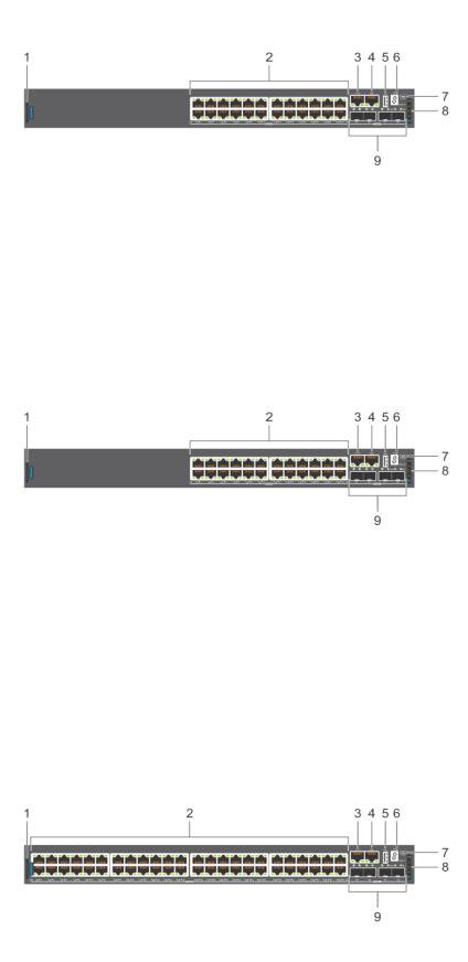
1. |
Luggage tag |
2. |
2.5GBASE-T RJ45 multigigabit ports |
3. |
RJ45 serial management port |
4. |
RJ45 Ethernet console port |
5. |
USB Type-A port |
6. |
Stack ID |
7. |
MicroUSB Type-B port |
8. |
Status LEDs |
9. |
25G SFP28 ports |
|
|
N2224PX-ON I/O-side view
1. |
Luggage tag |
2. |
2.5GBASE-T RJ45 ports: |
|
|
|
● First 12 ports with 802.at (30W) PoE |
|
|
|
● Second 12 ports with 802.3bt Type-3 (60W) PoE |
3. |
RJ45 serial management port |
4. |
RJ45 Ethernet console port |
5. |
USB Type-A port |
6. |
Stack ID |
7. |
MicroUSB Type-B port |
8. |
Status LEDs |
9. |
25G SFP28 ports |
|
|
N2248X-ON I/O-side view
1. |
Luggage tag |
2. |
2.5GBASE-T RJ45 multigigabit ports |
3. |
RJ45 serial management port |
4. |
RJ45 Ethernet console port |
5. |
USB Type-A port |
6. |
Stack ID |
8 N2200-ON Series switch
7. |
MicroUSB Type-B port |
8. Status LEDs |
9. |
25G SFP28 ports |
|
N2248PX-ON I/O-side view
1. |
Luggage tag |
2. |
2.5GBASE-T RJ45 ports: |
|
|
|
● First 24 ports with 802.at (30W) PoE |
|
|
|
● Second 24 ports with 802.3bt Type-3 (60W) PoE |
3. |
RJ45 serial management port |
4. |
RJ45 Ethernet console port |
5. |
USB Type-A port |
6. |
Stack ID |
7. |
MicroUSB Type-B port |
8. |
Status LEDs |
9. |
25G SFP28 ports |
|
|
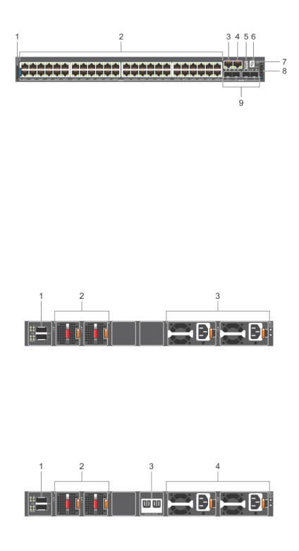
N2200-ON Series PSU-side views
N2224X-ON PSU-side view
1.40G QSFP+ stacking ports
2.Fans
3.AC or DC PSUs
N2224PX-ON PSU-side view
1. |
40G QSFP+ stacking ports |
2. |
Fans |
3. |
Input for external power shelf (MPS-1S shelf and MPS-3S |
4. |
AC or DC PSUs |
|
shelf) |
|
|
N2200-ON Series switch |
9 |
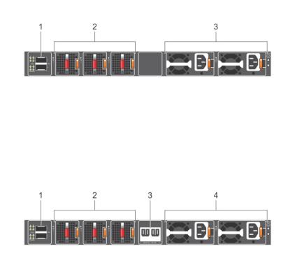
N2248X-ON PSU-side view
1.40G QSFP+ stacking ports
2.Fans
3.AC or DC PSUs
N2248PX-ON PSU-side view
1. |
40G QSFP+ stacking ports |
2. |
Fans |
3. |
Input for external power shelf (MPS-1S shelf and MPS-3S |
4. |
AC or DC PSUs |
|
shelf) |
|
|
Features
The N2200-ON Series switches offer the following features:
●Ports:
○N2224X-ON—1 U, 24 multigigabit ports 2.5GBASE-T RJ24, four ports 25G SFP28, and two ports of 40G QSFP+ for stacking
○N2224PX-ON—1 U, 24 multigigabit ports 2.5GBASE-T RJ24: 12 ports of 802.3at (30W) PoE, 12 ports of 802.3bt Type-3 (60W) PoE, four ports 25G SFP28, and two ports of 40G QSFP+ for stacking
○N2248X-ON—1 U, 48 multigigabit ports 2.5GBASE-T RJ24, four ports 25G SFP28, and two ports of 40G QSFP+ for stacking
○N2248PX-ON—1 U, 48 multigigabit ports 2.5GBASE-T RJ24: 24 ports of 802.3at (30W) PoE and 24 ports of 802.3bt Type-3 (60W) PoE, four ports 25G SFP28, and two ports of 40G QSFP+ for stacking
●One MicroUSB Type-B console port
●One RJ45 serial console port
●One USB Type-A port for more file storage
●Two-core Denverton-NS CPU, 4GB DDR4-1866 SO-DIMM, one 8GB M.2 SATA SSD.
●One 10/100/1000BaseT Ethernet management port
●Two pluggable AC or DC PSUs
●N2224X-ON and N2224PX-ON—Two fan modules
●N2248X-ON and N2248PX-ON—Three fan modules
●N2224X-ON and N2248X-ON—Normal and reverse airflow options
●N2224PX-ON and N2248PX-ON—external power supply connectors to connect the MPS-1S or MPS-3S shelf
●N2224PX-ON and N2248PX-ON—(optional) external power supply
●System ground connector
●Switch-monitoring LEDs
10 N2200-ON Series switch
Physical dimensions
The N2200-ON Series switches have the following physical dimensions, excluding the PSU and fan tray handle:
●1.71 in x 17.09 in x 15.75 in (H x W x D)
●43.5 mm x 434 mm x 400 mm (H x W x D)
(PSU and fan tray handle adds 1.18 in or 30 mm)
LED display
The N2200-ON Series switch includes LED displays on the I/O side of the switch. This section describes open networking installation environment (ONIE) LED behaviors. Some LED behaviors may change after you install your software.
LED behavior
The following N2200-ON Series switch LED behavior is seen during ONIE operations:
N2200-ON Series LEDs
1. |
Port activity LEDs |
2. |
Management port activity LEDs |
3. |
SFP28 Port activity LEDs |
4. |
Stack ID LED |
5. |
Stack Master LED |
6. |
System Status/Health LED |
7. |
Power LED |
8. |
Fan LED |
9. |
Locator LED/System Beacon |
10. |
Stacking port activity LEDs |
N2200-ON Series switch |
11 |
Table 2. N2200-ON Series switch LED behavior
LED |
Description |
|
|
|
|
|
|
|
7-Segment LED for stacking |
● |
Off—No power |
|
● Solid green—Hex digit representing the stack unit ID |
|
Stack Master LED |
● |
Off—Switch is in Stacking Slave mode |
|
● Solid green—Switch is in Stacking Master or Standalone |
|
|
|
mode |
|
|
|
System Status/Health LED |
● |
Solid green—Normal operation |
|
● |
Flashing green—Booting |
|
● Solid yellow—Critical system error; major fault |
|
|
● Flashing yellow—Noncritical system error, minor fault, fan |
|
|
|
failure, or power supply failure |
|
|
|
Power LED |
● |
Off—No power |
|
● |
Solid Green—Normal operation |
|
● Solid yellow—POST is in process |
|
|
● Flashing yellow—Power supply failed |
|
FAN LED |
● |
Off—No power |
|
● Solid green—Normal operation; fan powered and running |
|
|
|
at the expected RPM |
|
● Flashing yellow—Fan fault—including incompatible airflow |
|
|
|
direction when you insert the PSU, fan trays with differing |
|
|
airflows, missing a fan, or fan tray not functioning properly |
|
|
|
LOCATOR LED/System Beacon |
● |
Off—Locator function disabled |
|
● Flashing blue—Locator function enabled |
|
|
|
|
Table 3. 1000MBase-T and 10/100MBase-T PoE System management Ethernet port LEDs |
|
|
|
LED |
Description |
|
|
|
|
Link LED |
● Off—No link |
|
● Solid green—Link operating at a maximum speed, |
|
autonegotiated/forced to 1000MBase-T mode |
|
● Solid yellow—Link operating at a lower speed, |
|
autonegotiated/forced or 10/100MBase-T mode |
|
|
Activity LED |
● Off—No activity |
|
● Solid Yellow—No port activity and PoE power on |
|
● Flashing green—Port activity and PoE power off |
|
● Flashing yellow—Port activity and PoE power on |
|
|
Table 4. 1000MBase-T and 10/100MBase-T non-PoE System management Ethernet port LEDs
LED |
Description |
|
|
|
|
|
|
|
Link LED |
● |
Off—No link |
|
● Solid green—Link operating at a maximum speed, |
|
|
|
autonegotiated/forced to 1000MBase-T mode |
|
● Solid yellow—Link operating at a lower speed, |
|
|
|
autonegotiated/forced or 10/100MBase-T mode |
|
|
|
Activity LED |
● |
Off—No activity |
|
● |
Flashing green—Port activity |
|
|
|
Table 5. 2.5G Base-T PoE port LEDs
LED |
Description |
|
|
|
|
Link LED |
All four LEDs: |
|
● Off—No link |
|
|
12 N2200-ON Series switch
Table 5. 2.5G Base-T PoE port LEDs (continued)
LED |
Description |
|
|
|
|
|
● Solid green—Link operating at maximum speed, |
|
autonegotiated/forced to 2.5GBase-T mode |
|
● Solid yellow—Link operating at a lower speed, |
|
autonegotiated/forced to 10/100/1000MBase-T |
|
● Flashing green, ~30ms—Port activity |
Activity LED |
● Off—No activity and PoE power off |
|
● Solid yellow—No port activity and PoE power on |
|
● Flashing green—port activity and PoE power off |
|
● Flashing yellow—port activity and PoE power on |
|
|
Table 6. 2.5G Base-T non-PoE port LEDs
LED |
Description |
|
|
|
|
|
|
|
Link LED |
All four LEDs: |
|
|
● |
Off—No link |
|
● Solid green—Link operating at maximum speed, |
|
|
|
autonegotiated/forced to 2.5GBase-T mode |
|
● Solid yellow—Link operating at a lower speed, |
|
|
|
autonegotiated/forced to 10/100/1000MBase-T |
|
|
|
Activity LED |
● |
Off—No activity |
|
● Flashing green, ~30ms—Port activity |
|
|
|
|
Table 7. SFP28 port LEDs
LED |
Description |
|
|
|
|
|
|
|
Link LED |
All four LEDs: |
|
|
● |
Off—No link |
|
● Solid green—Link operating at maximum speed, 25G |
|
|
● Solid yellow—Link operating at a speed less than 25G |
|
|
● Flashing green, ~30ms—Port activity |
|
Activity LED |
● |
Off—No activity |
|
● Flashing green—port activity at maximum speed |
|
|
● Flashing yellow—port activity at lower speed |
|
|
|
|
All four QSFP+ port LEDs are used with 4x10 GbE mode. |
|
|
Table 8. QSFP+ stacking port LEDs |
|
|
|
|
|
LED |
Description |
|
|
|
|
|
|
|
Link LED |
All four LEDs: |
|
|
● |
Off—No link |
|
● Solid green—Link operating at maximum speed, 40G |
|
|
● Solid yellow—Link operating at a speed less than 40G |
|
Activity LED |
● |
Off—No activity |
|
● Flashing green, ~30ms—Port activity operating at |
|
|
|
maximum speed, 40G |
|
● Flashing yellow, ~30ms—Port activity operating at less |
|
|
|
than 40G |
|
● Flashing yellow, 1 second on/off—port beacon |
|
|
|
|
N2200-ON Series switch |
13 |

Prerequisites
The following is a list of components that are required for successful switch installation:

 NOTE: For detailed installation instructions, see Site preparations and N2200-ON Series switch installation.
●N2200-ON Series switch or multiple switches, if stacking
●AC or DC countryand regional-specific cables to connect the AC or DC power source to the AC or DC PSU
●Hot-swappable AC or DC PSUs; minimum one AC or DC PSU
●Hot-swappable fan modules
●#1 and #2 Phillips screwdrivers, not included
●Torx screwdriver, not included
●Copper or fiber cables
●L-bracket and screws for two-post rack mount
●DC only: Ground lug and screws
●Rubber feet
Other optional components are:
●Extra mounting brackets and screws
●Second AC or DC PSU
●MPS-1S shelf
●MPS-3S shelf
N2200-ON Series switch configurations
You can order the N2200-ON Series switch in several different configurations.
●N2200-ON Series AC or DC Normal Airflow switch:
○N2224X-ON—one U, 24 ports 2.5GBASE-T RJ24, four ports 25G SFP28, two 40G ports QSFP+ for stacking, two pluggable AC or DC PSUs, and two fan subsystems
○N2224PX-ON—one U, 24 ports 2.5GBASE-T RJ24 made up of 12 ports 802.3 Type-2 30W PoE and 12 ports 802.3bt Type-3 60W PoE, four ports 25G SFP28, two 40G ports QSFP+ for stacking, two pluggable AC or DC PSUs, (optional) one EPS, and two fan subsystem
○N2248X-ON—one U, 48 ports 2.5GBASE-T RJ24, four ports 25G SFP28, two 40G ports QSFP+ for stacking, two pluggable AC or DC PSUs, and three fan subsystems
○N2248PX-ON—one U, 48 ports 2.5GBASE-T RJ24 made up of 24 ports 802.3 Type-2 30W PoE and 24 ports 802.3bt Type-3 60W PoE, four ports 25G SFP28, two 40G ports QSFP+ for stacking, two pluggable AC or DC PSUs, (optional) one EPS, and three fan subsystem
●N2200-ON Series AC Reverse Airflow switch:
○N2224X-ON—one U, 24 ports 2.5GBASE-T RJ24, four ports 25G SFP28, two 40G ports QSFP+ for stacking, two pluggable AC PSUs, and two fan subsystems with airflow from the power supply side to the I/O side

 NOTE: Reverse airflow is not supported on the N2224X-ON DC switch.
○N2248X-ON—one U, 48 ports 2.5GBASE-T RJ24, four ports 25G SFP28, two 40G ports QSFP+ for stacking, two pluggable AC PSUs, and three fan subsystems with airflow from the power supply side to the I/O side

 NOTE: Reverse airflow is not supported on the N2248X-ON DC switch.
Fan and PSU airflow
●N2224X-ON and N2248X-ON—Fans have airflow from the I/O side to the PSU side (normal) and airflow from the PSU side to the I/O side (reverse).
●N2224PX-ON and N2248PX-ON—Fans have airflow from the I/O side to the PSU side (normal).
●AC or DC power supply has airflow from the I/O side to the PSU side (normal).
●AC power supply also has airflow from the PSU side to the I/O side (reverse).
14 N2200-ON Series switch
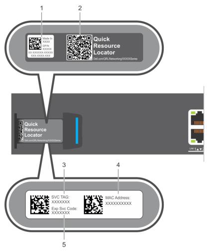
Luggage tag
The switch has a pull-out tag, which is known as a luggage tag, on the PSU-side of the switch. The front of the luggage tag includes switch ID information. The back of the luggage tag includes a QRL that takes you to a How-To site where you can watch videos about racking the switch, replacing components, configuring port channels, and so on.
N2224PX-ON and N2224X-ON luggage tag
1. |
Product ID QRL |
2. |
Product information QRL |
3. |
SVC tag |
4. |
MAC address |
5. |
Exp Svc code |
|
|
N2248PX-ON and N2248X-ON luggage tag
N2200-ON Series switch |
15 |

1. |
Product ID QRL |
2. |
Product information QRL |
3. |
SVC tag |
4. |
MAC address |
5. |
Exp Svc code |
|
|
16 N2200-ON Series switch

3
Site preparations
The N2200-ON Series switch is suitable for installation as part of a common bond network (CBN).
You can install the switch in:
●Network telecommunication facilities
●Data centers
●Other locations where the National Electric Code (NEC) applies

 NOTE: Install the switch into a rack or cabinet before installing any additional components such as cables or optics.
Topics:
•Site selection
•Cabinet placement
•Rack mounting
•Switch ground
•Fans and airflow
•Power
•Storing components
Site selection
Install the switch equipment in restricted access areas.
A restricted access area is one in which service personnel can only gain access using a special tool, lock, key or other means of security. The authority responsible for the location controls access to the restricted area.
Ensure that the area where you install your switch meets the following safety requirements:
●Near an adequate power source. Connect the switch to the appropriate branch circuit protection according to your local electrical codes.
●Switch environmental temperature range is from 0° to 45°C (32° to 113°F).
●Relative humidity is from 5 to 95 percent (RH), noncondensing.
●In a dry, clean, well-ventilated, and temperature-controlled room, away from heat sources such as hot air vents or direct sunlight
●Away from sources of severe electromagnetic noise.
●Inside the restricted access area, positioned in a rack or cabinet, or on a desktop with adequate space in the front, back, and sides for proper ventilation and access
●Install the switch in Information Technology Rooms in accordance with Article 645 of the National Electrical Code and NFPA 75.
For more information about switch storage and environmental temperatures, see Specifications.
Cabinet placement
Install the N2200-ON Series switch only in indoor cabinets that are designed for use in a controlled environment.
Do not install the switch in outside cabinets. For cabinet placement requirements, see Site selection.
The cabinet must meet minimum size requirements. Airflow must be in accordance with the Electronic Industries Alliance (EIA) standard. Ensure that there is a minimum of 5 inches (12.7 cm) between the intake and exhaust vents and the cabinet wall.
Site preparations |
17 |

Rack mounting
When you prepare your equipment rack, ensure that the rack is grounded.
Ground the equipment rack to the same ground point the power service in your area uses. The ground path must be permanent.
Switch ground
Dell Technologies recommends you ground your switch. Use the N2200-ON Series switch in a common bond network (CBN).
Connect the grounding cables as described in N2200-ON Series switch installation.
 NOTE: For an AC-powered switch, although the third conductor of the AC power cable provides a ground path, Dell Technologies recommends grounding your switch with a dedicated ground wire.
 NOTE: For a DC-powered switch, the only way to safely ground your switch is to attach a dedicated ground wire. The ground lug kit ships in a plastic bag that is placed with the other accessories inside the shipping box. To ground your switch, first attach the ground lug to the switch using the screws. Then attach the DC ground wire to the ground lug.
Fans and airflow
The N2200-ON Series switch fans support two airflow options: normal and reverse.

 NOTE: Reverse airflow is only supported on the N2224X-ON and N2248X-ON AC switches.
Fan combinations
Fan installation is completed as part of the factory install based on stock keeping unit (SKU) type. The N2200-ON Series switch has SKUs that support the following configurations:
●AC or DC PSU with fan airflow from the I/O to the PSU—the red indicator on the handle is the normal airflow direction.
●AC PSU with fan airflow from the PSU to the I/O—the blue indicator on the handle is the reverse airflow direction.
Order the fans suitable to support the ventilation at your site. Use a single type of airflow fan in your switch. Do not mix reverse and normal airflows in a single N2200-ON Series switch.
For proper ventilation, position the switch in an equipment rack or cabinet with a minimum of 5 inches (12.7 cm) of clearance around the exhaust vents. When you install two N2200-ON switches near each other, to permit proper airflow, position the two switches at least 5 inches (12.7 cm) apart. The fan speed varies based on internal temperature monitoring. The N2200-ON Series switch never intentionally turns off the fans.
For more information, see Fans.
Power
To connect the switch to the applicable power source, use the appropriate power cable. An AC power cable is included with each PSU. If you optionally order DC PSUs, they ship with a DC power cable.
When installing AC or DC switches, follow the requirements of the National Electrical Code, ANSI/NFPA 70, where applicable.
The switch is powered-up when you connect the power cable between the switch and the power source. For more information, see Power supplies.

 NOTE: This equipment must be earthed. Connect the power plug to a properly wired earth ground socket outlet.
 CAUTION: Always disconnect the power cable before you service the power slots. The switch has multiple power cables. Before servicing, ensure that all power cables are disconnected.
 CAUTION: On an AC switch, use the power cable as the main disconnect device. Ensure that the socket-outlet is located and installed near the equipment and is accessible.
18 Site preparations


 NOTE: Software controls the module power. You do not see module LEDs when the switch powers up in ONIE.
Storing components
If you do not install your N2200-ON Series switch and components immediately, properly store the switch and all components using these guidelines:
●Storage location temperature must remain constant. The storage range is from -40°C to 70°C (-40°F to 158°F).
●Store on a dry surface or floor, away from direct sunlight, heat, and air conditioning ducts.
●Store in a dust-free environment.
 NOTE: ESD damage can occur when components are mishandled. Always wear an ESD-preventive wrist or heel ground strap when handling the N2200-ON Series switch and accessories. After you remove the original packaging, place the N2200-ON Series switch and components on an antistatic surface.
Site preparations |
19 |

4
N2200-ON Series switch installation
To install the N2200-ON Series switch, complete the installation procedures in the order that is presented in this chapter.
Always handle the switch and components with care. Avoid dropping the switch or its field replaceable units (FRUs).
 NOTE: ESD damage can occur if components are mishandled. Always wear an ESD-preventive wrist or heel ground strap when handling the N2200-ON Series switch and components. As with all electrical devices of this type, take all the necessary safety precautions to prevent injury when installing this switch.
Topics:
•Unpack
•Rack or cabinet hardware installation
•Ground cable
•Desktop
•Two-post five-inch-offset switch installation
•Two-post flush-mount switch installation
•Wallor ceiling-mount switch installation
•One RU ReadyRails installation
•Optics installation
•Switch start-up
•After switch placement
•Switch replacement
Unpack

 NOTE: Before unpacking the switch, inspect the container and immediately report any evidence of damage. When unpacking the switch, ensure that the following items are included:
●One N2200-ON Series switch
●One RJ45 to DB-9 female cable
●One MicroUSB console cable
●One set of rack mounting brackets and screws
●Four rubber feet
●One pluggable AC PSU (and second AC PSU if ordered)
●One or two pluggable DC PSUs (if ordered)
●Two or three pluggable fan units, depending on the switch model
●One AC power cable, country or region specific
●DC only: DC power cables
●N2200-ON Series Quick Setup Guide
●N2200-ON Series Warnings Guide
●Safety and Regulatory Information
●Warranty and Support Information
Unpacking Steps
Unpack the system carefully.
1.Place the container on a clean, flat surface and cut all straps securing the container.
2.Open the container, or remove the container top.
20 N2200-ON Series switch installation
 Loading...