

Dell PowerSwitch N1100-ON User Manual [zh]

Dell Networking
N1108T-ON/N1108P-ON/
N1108EP-ON/N1124T-ON/
N1124P-ON/N1148T-ON/
N1148P-ON Switches
Getting Started Guide
使用入门指南
入門指南
『はじめに』
설명서는
Regulatory Model: E17W and E18W
Regulatory Type: E17W001/E18W001/E18W002

Dell Networking
N1108T-ON/N1108P-ON/
N1108EP-ON/N1124T-ON/
N1124P-ON/N1148T-ON/
N1148P-ON Switches
Getting Started Guide
Regulatory Models: E17W and E18W

Notes, Cautions, and Warnings
NOTE: A NOTE indicates important information that helps you make better use of
your switch.
CAUTION: A CAUTION indicates either potential damage to hardware or loss of
data and tells you how to avoid the problem.
WARNING: A WARNING indicates a potential for property damage, personal
injury, or death.
Lithium battery caution:
• There is a danger of explosion if a battery is incorrectly replaced. Replace
only with the same or equivalent type. Dispose batteries of according to
the manufacturer's instructions.
• Disposing a battery into fire, a hot oven, mechanically crushing, or cutting
it can result in an explosion.
• Leaving a battery in an extremely hot environment can result in leakage of
flammable liquid, gas, or an explosion.
• If a battery is subjected to extremely low air pressure, it may result in
leakage of flammable liquid, gas, or an explosion.
• The device can only be used in a fixed location such as a lab or a machine
room. When you install the device, ensure that the protective earthing
connection of the socket-outlet is verified by a skilled person.
___________________
© 2019 Dell Inc. or its subsidiaries. All rights reserved. This product is protected by U.S. and
international copyright and intellectual property laws. Dell and the Dell logo are trademarks of Dell
Inc. in the United States and/or other jurisdictions. All other marks and names mentioned herein may
be trademarks of their respective companies.
Regulatory Models: E17W and E18W
May 2019 P/N JJHMV Rev. A01

Contents
1 Introduction . . . . . . . . . . . . . . . . . . . . . . . . 5
N1100-ON Series Hardware Overview . . . . . . . . . . 5
Power Consumption for N1100-ON Series
PoE Switches
Ventilation System
. . . . . . . . . . . . . . . . . . . . . 5
. . . . . . . . . . . . . . . . . . 6
N1100-ON Series Model Summary
. . . . . . . . . . . . 7
2 N1108T-ON/N1108P-ON/N1108EP-ON
Installation . . . . . . . . . . . . . . . . . . . . . . . . 8
Mounting an N1108T-ON/N1108P-ON Switch Using
Dell Tandem Tray . . . . . . . . . . . . . . . . . . . . . 8
Mounting an N1108T-ON/N1108P-ON/N1108EP-ON
on a Two-Post Rack Using Large L-brackets
Mounting all N11xx-ON Switches on a Wall
. . . . . . . 9
. . . . . . 10
3 N1124T-ON/N1124P-ON/N1148T-ON/
N1148P-ON Installation . . . . . . . . . . . . . . 13
Rack Mounting an N1124T-ON/N1124P-ON/
N1148T-ON/ N1148P-ON Switch. . . . . . . . . . . . . 13
Installing in a Rack
Installing as a Free-standing Switch . . . . . . . . 14
Stacking Multiple N1124T-ON/N1124P-ON/
N1148T-ON/ N1148P-ON Switches
. . . . . . . . . . . . . . . . . 13
. . . . . . . . . . . 14
Contents 3

4 Starting and Configuring the
N1100-ON Series Switch . . . . . . . . . . . . . 15
Connecting an N1100-ON Series Switch to
a Terminal . . . . . . . . . . . . . . . . . . . . . . . . 16
Connecting an N1100-ON Series Switch to
a Power Source
AC and DC Power Connection
. . . . . . . . . . . . . . . . . . . . . 17
. . . . . . . . . . . 17
Booting the N1100-ON Series Switch
. . . . . . . . . . 18
Performing the N1100-ON Series
Initial Configuration
Enabling Remote Management
Initial Configuration Procedure
. . . . . . . . . . . . . . . . . . . 19
. . . . . . . . . . . 19
. . . . . . . . . . . 20
Example Session . . . . . . . . . . . . . . . . . . 21
Dell Easy Setup Wizard Console Example
Next Steps
. . . . . . . . . . . . . . . . . . . . . 26
. . . . . 22
5 Agency compliance . . . . . . . . . . . . . . . . 28
6 Operating Altitude–Information Update 31
4 Contents

Introduction
This document provides basic information about the Dell Networking
N1100-ON Series switches, including how to install a switch and perform the
initial configuration. For information about how to configure and monitor
switch features, refer to the User Configuration Guide, which is available on
the Dell Support website at dell.com/support. See the Support website for
the latest updates on documentation and firmware.
NOTE: Switch administrators are strongly advised to maintain Dell Networking
switches on the latest version of the Dell Networking Operating System (DNOS).
Dell Networking continually improves the features and functions of DNOS based on
feedback from you, the customer. For critical infrastructure, pre-staging of the new
release into a non-critical portion of the network is recommended to verify network
configuration and operation with the new DNOS version.
N1100-ON Series Hardware Overview
This section contains information about device characteristics and modular
hardware configurations for the Dell Networking N1100-ON Series switch.
The N1108EP-ON switch uses an external power adaptor. There is no mounting kit
NOTE:
available for the N1108EP-ON external power adaptor. When installing the
N1108EP-ON, place the external power adaptor away from the switch.
Power Consumption for N1100-ON Series PoE Switches
Table 1-1 describes the power consumption for N1100-ON Series PoE
switches. The PoE power budget is 60W for the N1108P-ON, 123W for the
N1108EP-ON, 185W for the N1124P-ON, and 370W for the N1148P-ON.
Table 1-1. Power Consumption for N1100-ON Series PoE Switches
Model Input Voltage Power Supply
Configuration
N1108P-ON 100V/60Hz Main PSU 0.95A 88.64W
110V/60Hz Main PSU 0.87A 88.43W
120V/60Hz Main PSU 0.80A 88.22W
220V/50Hz Main PSU 0.49A 89.28W
240V/50Hz Main PSU 0.45A 89.70W
Maximum Steady
Current
Consumption (A)
Getting Started Guide 5
Maximum
Steady
Power (W)

Model Input Voltage Power Supply
Configuration
N1108EP-ON 100V/60Hz 54VDC External
power adaptor
110V/60Hz 54VDC External
power adaptor
120V/60Hz 54VDC External
power adaptor
220V/50Hz 54VDC External
power adaptor
240V/50Hz 54VDC External
power adaptor
N1124P-ON 100V/60Hz Main PSU 2.66A 260.66W
110V/60Hz Main PSU 2.38A 257.95W
120V/60Hz Main PSU 2.16A 256.27W
220V/50Hz Main PSU 1.18A 250.52W
240V/50Hz Main PSU 1.10A 251.25W
N1148P-ON 100V/60Hz Main PSU 4.78A 476.03W
110V/60Hz Main PSU 4.32A 472.64W
120V/60Hz Main PSU 3.95A 470.58W
220V/50Hz Main PSU 2.14A 459.37W
240V/50Hz Main PSU 1.97A 459.06W
Maximum Steady
Current
Consumption (A)
1.62A 157W
1.47A 157W
1.35A 157W
0.74A 157W
0.67A 157W
Maximum
Steady
Power (W)
Ventilation System
One fan cools the N1108T-ON/N1108P-ON switches, and two fans cool the
N1024T-ON/N1024P-ON/N1048T-ON/N1048P-ON switches. The fans are
not field replaceable. The N1108EP-ON is a fanless switch.
6 Getting Started Guide

N1100-ON Series Model Summary
Table 1-2. N1100-ON Series Switch Regulatory Numbers
Marketing
Model Name
(MMN)
N1108T-ON 10x1G/2x1G SFP Ports DPS-24GP E17W E17W001
N1108P-ON 10x1G/2x1G SFP/2xPoE+ Ports DPS-80AP/
N1108EP-ON8x1G PoE+/2x1G PD/2x1G SFP
N1124T-ON 24x1G/4x10G SFP+ Ports DPS-40AP E18W E18W001
N1124P-ON 24x1G/4x10G SFP+/6xPoE+ Ports EDPS-250BF E18W E18W001
N1148T-ON 48x1G/4x10G SFP+ Ports DPS-60AP E18W E18W002
N1148P-ON 48x1G/4x10G SFP+/12xPoE+ Port YM-2501D E18W E18W002
Description Power Supply
Unit (PSU)
DPS-24GP
ADP-280BR E48W E48W001
Ports
Regulatory
Model Number
(RMN)
E17W E17W001
Regulatory
Type Number
(RTN)
Getting Started Guide 7
N1108T-ON/N1108P-ON/N1108EPON Installation
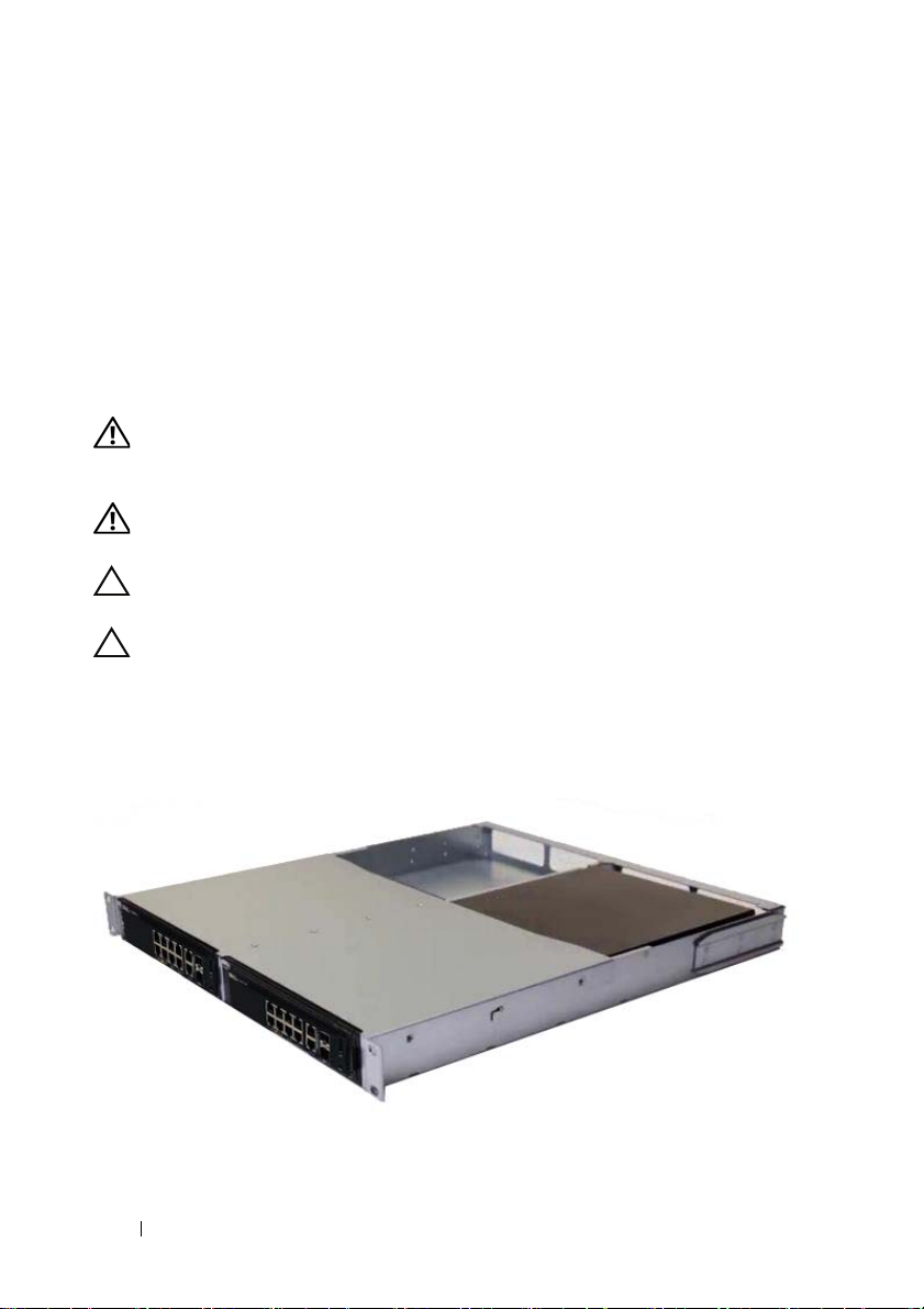
Mounting an N1108T-ON/N1108P-ON Switch Using Dell Tandem Tray
The AC power connector is on the rear panel.
WARNING: Read the safety information in the
as well as the safety information for other switches that connect to or support the
switch.
WARNING: Do not use rack mounting kits to suspend the switch from under a
table or desk, or attach it to a wall.
CAUTION: Disconnect all cables from the switch before continuing. Remove all
self-adhesive pads from the underside of the switch, if they have been attached.
CAUTION: When mounting multiple switches into a rack, mount the switches
from the bottom up.
1
Secure the N1108T-ON/N1108P-ON switch in the Dell Tandem Tray Kit
as shown in Figure 1-1.
Figure 1-1. Dell Tandem Tray Kit
Safety and Regulatory Information
2
Insert the switch into the 48.26 cm (19 inch) rack, ensuring that the rack
mounting holes on the kit line up to the mounting holes in the rack.
8 Getting Started Guide
3
Secure the kit to the rack with either the rack bolts or cage nuts and cagenut bolts with washers (depending on the kind of rack you have). Fasten
the bolts on the bottom before fastening the bolts on the top.
Mounting an N1108T-ON/N1108P-ON/N1108EPON on a Two-Post Rack Using Large L-brackets
NOTE: The AC power connector is on the rear panel of the N1108T-ON/N1108P-ON
switches. The DC power connector for the N1108EP-ON is at the center of the rear
panel.
NOTE: The N1108EP-ON switch uses an external power adaptor. There is no mounting kit
available for the N1108EP-ON external power adaptor. When installing the
N1108EP-ON, place the external power adaptor away from the switch.
CAUTION: As the N1108EP-ON is a fanless switch, do not place the external power
adaptor on top of the switch to avoid overheating.
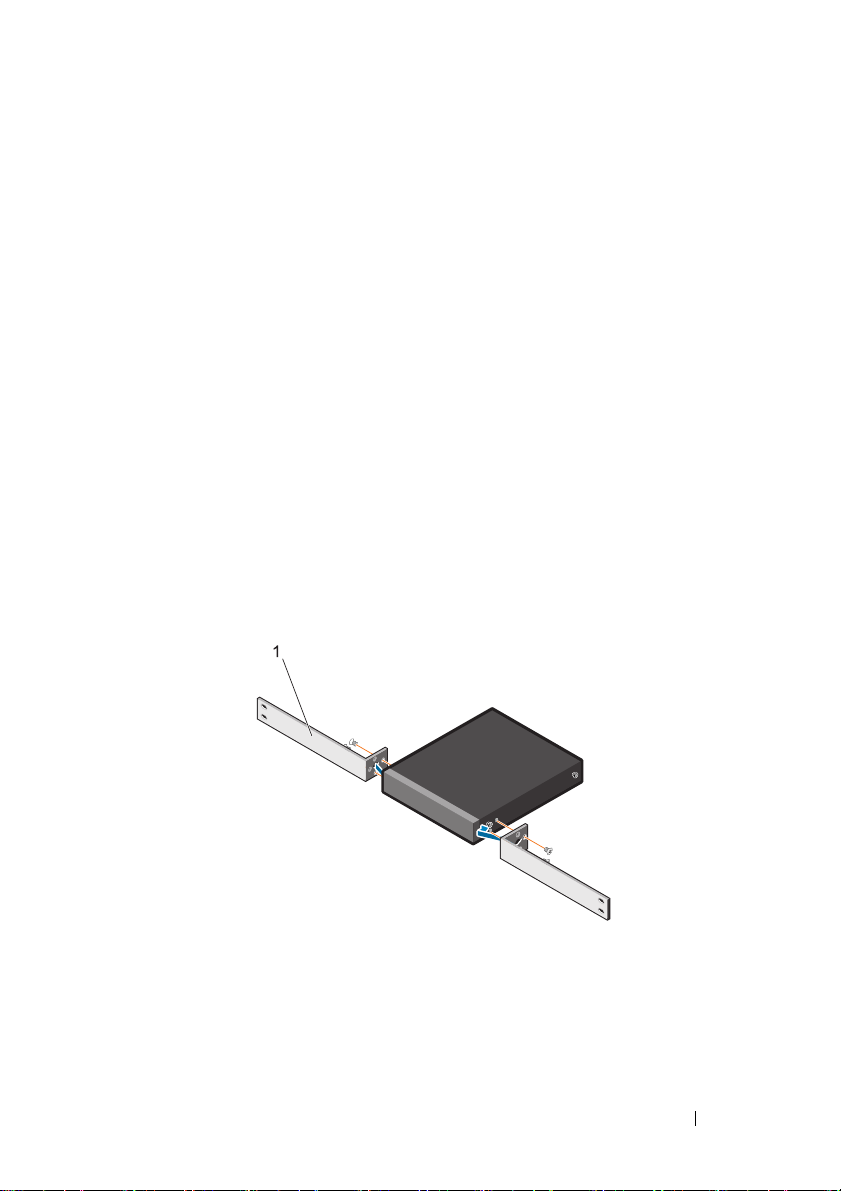
1
Place the supplied rack-mounting bracket on one side of the switch
making sure that the mounting holes on the switch line up to the
mounting holes on the rack mounting bracket. See item 1 in Figure 1-2.
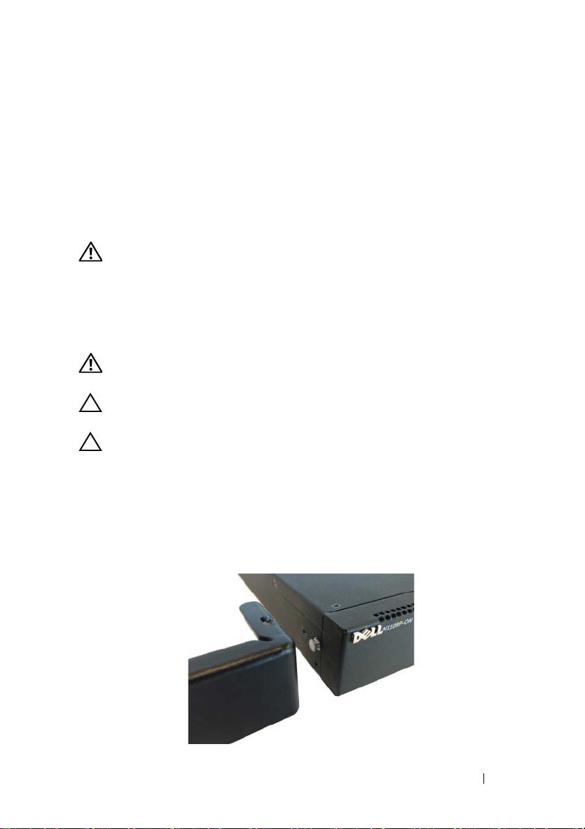
Figure 1-2. Installing Using Large L-bracket Kit
2
Insert the supplied screws into the rack mounting holes and tighten with a
screwdriver.
3
Repeat the process on the other side of the switch.
Getting Started Guide 9
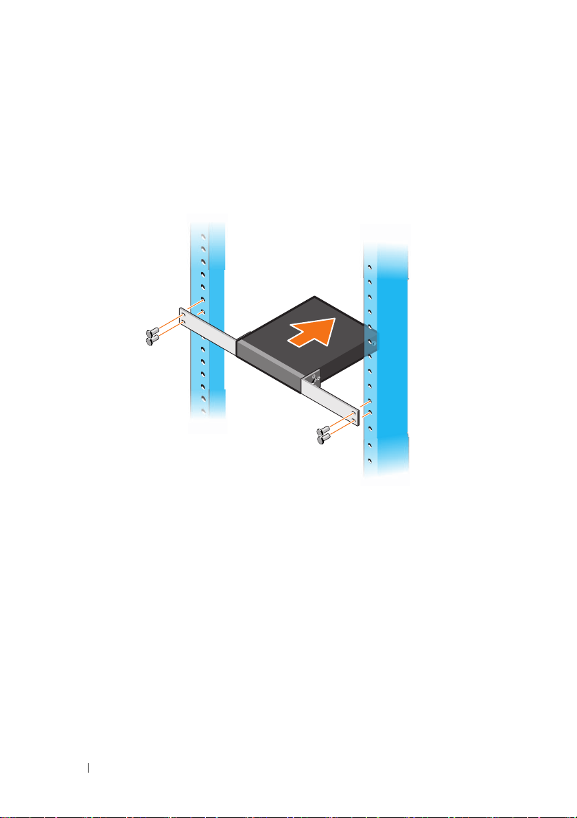
4
Insert the switch and rail assembly into the rack from the front of the rack.
Make sure that the rack-mounting holes on the switch line up to the
mounting holes on the rack.
5
Secure the switch to the rack with the rack screws. Fasten the lower pair of
screws before the upper pair of screws. See Figure 1-3.
Figure 1-3. Install on a Two-post Rack with L-Bracket
Mounting all N11xx-ON Switches on a Wall
1
Make sure that the mounting location meets the following requirements:
• The surface of the wall can support the switch.
• The location is ventilated to prevent heat buildup.
2
Place the supplied wall-mounting bracket on one side of the switch,
verifying that the mounting holes on the switch line up to the mounting
holes on the wall-mounting bracket.
3
Insert the supplied screws into the wall-mounting bracket holes and
tighten with a screwdriver. See Figure 1-4.
10 Getting Started Guide
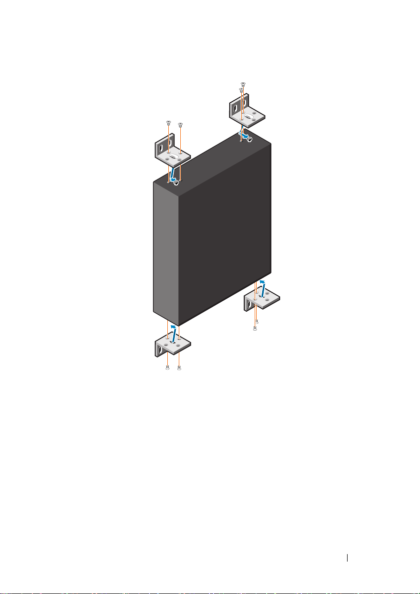
Figure 1-4. Inserting Mounting Brackets
4
Repeat the process for the wall-mounting bracket on the other side of the
switch.
5
Place the switch on the wall in the location where the switch is being
installed.
6
Mark the locations on the wall where the screws to hold the switch must be
prepared.
7
On the marked locations, drill the holes and place all the eight supplied
anchors in the holes.
8
Insert the supplied screws into the wall-mounting bracket holes and
tighten them with a screwdriver. See Figure 1-5.
Getting Started Guide 11
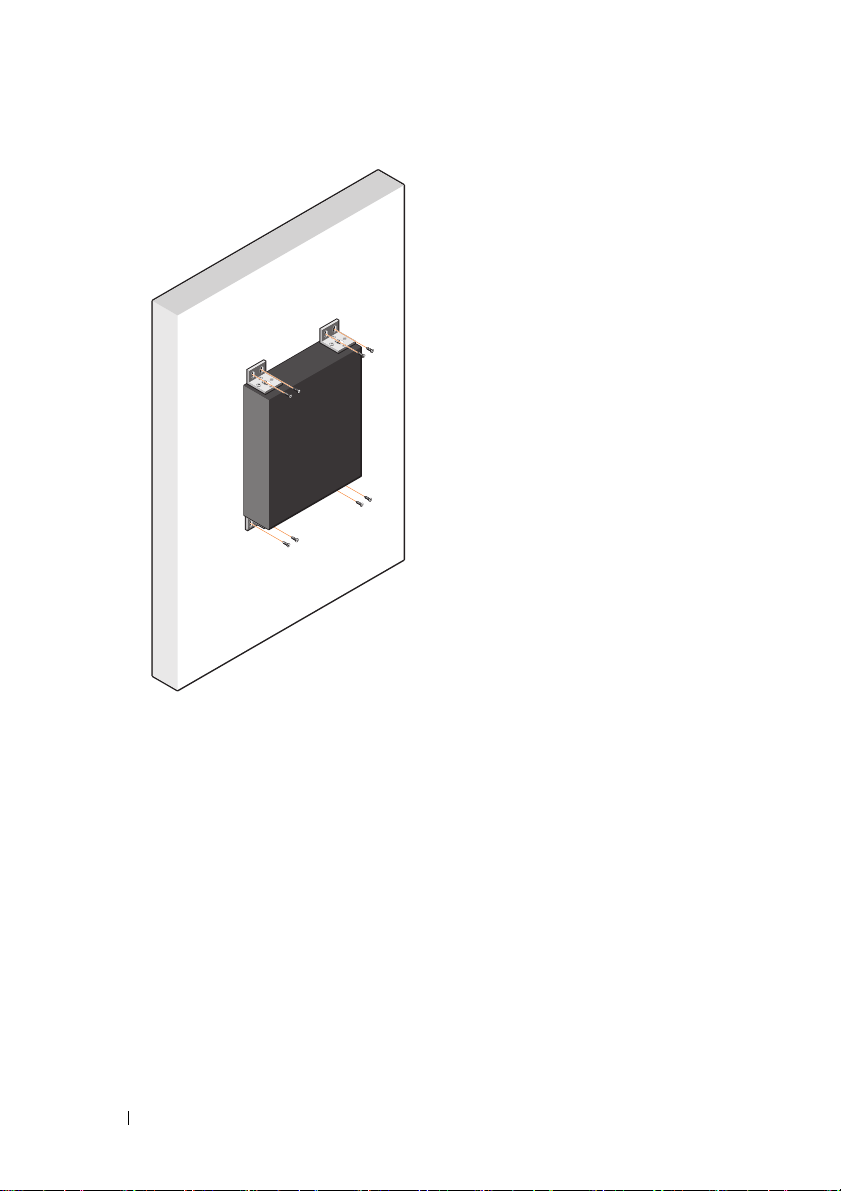
Figure 1-5. Mounting on a Wall
12 Getting Started Guide
N1124T-ON/N1124P-ON/N1148T-ON/ N1148P-ON Installation
Rack Mounting an N1124T-ON/N1124P-ON/ N1148T-ON/ N1148P-ON Switch
WARNING: Read the safety information in the
as well as the safety information for other switches that connect to or support the
switch.
The AC power connector is on the rear panel of the switch.
Safety and Regulatory Information
Installing in a Rack
WARNING: Do not use rack mounting kits to suspend the switch from under a
table or desk, or attach it to a wall.
CAUTION: Disconnect all cables from the switch before continuing. Remove all
self-adhesive pads from the underside of the switch, if they have been attached.
CAUTION: When mounting multiple switches into a rack, mount the switches
from the bottom up.
1
Place the supplied rack-mounting bracket on one side of the switch,
ensuring that the mounting holes on the switch line up to the mounting
holes in the rack-mounting bracket. Figure 1-6 illustrates where to mount
the brackets.
Figure 1-6. Attaching the Brackets
Getting Started Guide 13

2
Insert the supplied bolts into the rack-mounting holes and tighten with a
screwdriver.
3
Repeat the process for the rack-mounting bracket on the other side of the
switch.
4
Insert the switch into the 48.26 cm (19 inch) rack, ensuring that the rackmounting holes on the bracket line up with the mounting holes in the
rack.
5
Secure the bracket to the rack with either the rack bolts or cage nuts and
cage-nut bolts with washers (depending on the kind of rack you have).
Fasten the bolts on the bottom before fastening the bolts on the top.
CAUTION: Make sure that the supplied rack bolts fit the pre-threaded holes in the
rack.
NOTE: Make sure that the ventilation holes are not obstructed.
Installing as a Free-standing Switch
NOTE: Dell strongly recommends mounting the switch in a rack.
Install the switch on a flat surface if you are not installing it in a rack. The
surface must be able to support the weight of the switch and the switch
cables. The switch is supplied with four self-adhesive rubber pads.
1
Attach the self-adhesive rubber pads on each location marked on the
bottom of the switch.
2
Set the switch on a flat surface, and make sure that it has proper
ventilation by leaving 5 cm (2 inches) on each side and 13 cm (5 inches) at
the back.
Stacking Multiple N1124T-ON/N1124P-ON/ N1148T-ON/ N1148P-ON Switches
You can stack N1124T-ON/N1124P-ON/N1148T-ON/ N1148P-ON switches
up to four switches high using 10G SFP+ ports on the front of the switch.
The ports must be configured to support stacking. When multiple switches
are connected together through the stack ports, they operate as a single unit
with up to 208 front-panel ports. The stack operates and is managed as a
single entity. Refer to the User Configuration Guide and the CLI Reference
Guide for more information.
14 Getting Started Guide
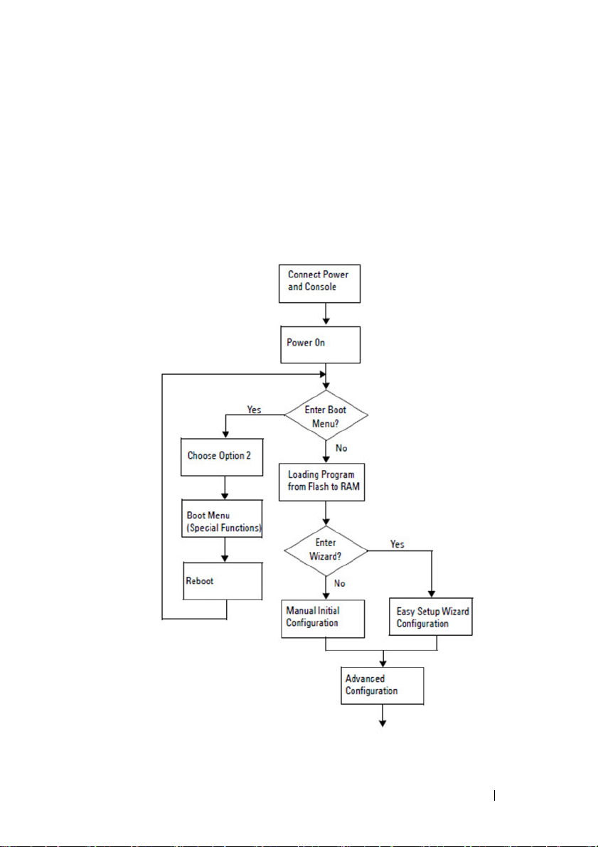
Starting and Configuring the N1100-ON Series Switch
The following flow chart provides an overview of the steps you use to perform
the initial configuration after the switch is unpacked and mounted.
Figure 1-7. Installation and Configuration Flow Chart
Getting Started Guide 15

Connecting an N1100-ON Series Switch to a Terminal
After completing all external connections, configure the switch by connecting
it to a terminal.
NOTE: Read the Release Notes for this product before proceeding. You can
download the Release Notes from the Dell Support website at dell.com/support.
NOTE: Dell recommends that you obtain the most recent version of the user
documentation from the Dell Support website at dell.com/support.
To monitor and configure the switch via the USB console, use the console
port on the front panel of the switch to connect it to a computer running
VT100 terminal emulation software using the supplied USB cable. It may be
necessary to download and install a driver on first use of the USB cable.
The following equipment is required to use the console port:
• VT100-compatible computer with a USB port running VT100 terminal
emulation software,
• The supplied USB cable with a type B USB connector for the console port
and USB connector for the host PC.
Perform the following tasks to connect a terminal to the switch console port:
1
Connect the USB type B connector on the supplied switch and connect
the other end to a computer running VT100 terminal emulation software.
2
Configure the terminal emulation software as follows:
a
Select the appropriate serial port (for example, COM 1) to connect to
the console.
b
Set the data rate to 115,200 baud.
c
Set the data format to 8 data bits, 1 stop bit, and no parity.
d
Set the flow control to none.
e
Set the terminal emulation mode to
f
Select Terminal keys for Function, Arrow, and Ctrl keys. Make sure
that the setting is for Terminal keys (not Microsoft Windows keys).
3
Connect the USB type B connector on the cable directly to the switch
console port. The Dell Networking console port is located on the right side
of the front panel and is labeled with a
such as HyperTerminal® and a USB driver.
VT100
.
|O|O|
symbol.
16 Getting Started Guide

NOTE: Console access to the stack manager is available from any console
port via the local CLI. Only one USB console session at a time is supported.
Connecting an N1100-ON Series Switch to a Power Source
CAUTION: Read the safety information in the
manual as well as the safety information for other switches that connect to or
support the switch.
The N1108T-ON and N1108P-ON models have one internal power supply.
The
power receptacle is on the rear panel. N1108EP-ON uses an external DC
power adaptor. The external DC power adaptor
Safety and Regulatory Information
AC and DC Power Connection
1
Make sure that the switch console port is connected to a PC running a
VT100 terminal emulator via the USB to USB Type B cable.
2
Using a 5-foot (1.5 m) standard power cable with safety ground connected,
connect the power cable to the AC main receptacle located on the rear
panel.
The PoE model switches have a heavy-duty power cable with a notched
connector for the switch power receptacle. Use of this type of cable is
mandatory for PoE-capable switches.
3
Connect the power cable to a grounded AC outlet.
Getting Started Guide 17

Booting the N1100-ON Series Switch
When the power is turned on with the local terminal already connected, the
switch goes through a power-on self-test (POST). POST runs every time the
switch is initialized and checks hardware components to determine if the
switch is fully operational before completely booting. If POST detects a
critical problem, the program flow stops. If POST passes successfully, valid
firmware is loaded into RAM. POST messages are displayed on the terminal
and indicate test success or failure. The boot process runs for approximately
60 seconds.
You can invoke the Boot menu after the first part of the POST is completed.
From the Boot menu, you can perform configuration tasks such as resetting
the system to factory defaults, activating the backup image, or recovering a
password. For more information about the Boot menu functions, refer to the
CLI Reference Guide.
18 Getting Started Guide

Performing the N1100-ON Series Initial Configuration
The initial configuration procedure is based on the following assumptions:
• The Dell Networking switch was never configured before.
• The Dell Networking switch booted successfully.
• The console connection was established, and the
prompt appears on the screen of a PC running terminal emulation
software.
The initial switch configuration is performed through the console port. After
the initial configuration, you can manage the switch from the alreadyconnected console port or remotely through an interface defined during the
initial configuration.
NOTE: The switch is not configured with a default user name, password, or IP
address.
Before setting up the initial configuration of the switch, obtain the following
information from your network administrator:
• The IP address to be assigned to the management interface.
• The IP subnet mask for the network.
• The IP address of the management interface default gateway.
These settings are necessary to allow the remote management of the switch
through Telnet (Telnet client) or HTTP (Web browser).
Dell Easy Setup Wizard
Enabling Remote Management
On the N1100-ON Series switches, you can use any of the switch ports on the
front panel for in-band management. By default, all in-band ports are
members of VLAN 1.
The Dell Easy Setup Wizard includes prompts to configure network
information for the VLAN 1 interface on the N1100-ON Series switches. You
can assign a static IP address and subnet mask or enable DHCP and allow a
network DHCP server to assign the information.
Refer to the CLI Reference Guide for commands to configure network
information.
Getting Started Guide 19

Initial Configuration Procedure
Perform the initial configuration by using the Dell Easy Setup Wizard or by
using the CLI. The wizard automatically starts when the switch configuration
file is empty. Exit the wizard at any point by entering [ctrl+z], but all
configuration settings specified will be discarded, and the switch will use the
default values.
NOTE: If you do not run the Dell Easy Setup Wizard or do not respond to the initial
Easy Setup Wizard prompt within 60 seconds, the switch enters CLI mode. You must
reset the switch with an empty startup configuration in order to rerun the Dell Easy
Setup Wizard.
For more information about performing the initial configuration by using the
CLI, refer to the CLI Reference Guide. This Getting Started Guide shows how
to use the Dell Easy Setup Wizard for initial switch configuration. The wizard
sets up the following configuration on the switch:
• Establishes the initial privileged user account with a valid password. The
wizard configures one privileged user account during the setup.
• Enables CLI login and HTTP access to use the local authentication setting
only.
• Sets up the IP address for the VLAN 1 routing interface, of which all
in-band ports are members.
• Sets up the SNMP community string to be used by the SNMP manager at
a given IP address. Skip this step if SNMP management is not used for this
switch.
• Allows you to specify the network management system IP address or
permit management access from all IP addresses.
• Configures the default gateway IP address for the VLAN 1 interface.
20 Getting Started Guide

Example Session
This section describes a Dell Easy Setup Wizard session. The following
values are used by the example session:
• The SNMP community string to be used is
• The network management system (NMS) IP address is
admin
• The user name is
, and the password is
• The IP address for the VLAN 1 routing interface is
subnet mask of
• The default gateway is
255.255.255.0
10.1.1.1.
.
The setup wizard configures the initial values as defined above. After
completing the wizard, the switch is configured as follows:
• SNMPv2 is enabled and the community string is set up as defined above.
SNMPv3 is disabled by default.
• The admin user account is set up as defined.
• A network management system is configured. From the management
station, you can access the SNMP, HTTP, and CLI interfaces. You may also
choose to allow all IP addresses to access these management interfaces by
choosing the (0.0.0.0) IP address.
• An IP address is configured for the VLAN 1 routing interface.
• A default gateway address is configured.
public
admin123
.
10.1.2.100
.
10.1.1.200
.
with a
NOTE: In the following example, the possible user options or default values are
enclosed in [ ]. If you press <Enter> with no options defined, the default value is
accepted. Help text is in parentheses.
Getting Started Guide 21

Dell Easy Setup Wizard Console Example
The following example contains the sequence of prompts and responses
associated with running an example Dell Easy Setup Wizard session, using
the input values listed earlier.
After the switch completes the POST and is booted, the following dialog
appears:
Unit 1 - Waiting to select management unit)>
___________Dell SupportAssist EULA__________________
I accept the terms of the license agreement. You can
reject the license agreement by configuring this
command 'eula-consent support-assist reject'.
By installing SupportAssist, you allow Dell to save
your contact information (e.g. name, phone number
and/or email address) which would be used to provide
technical support for your Dell products and services
Dell may use the information for providing
recommendations to improve your IT infrastructure.
Dell SupportAssist also collects and stores machine
diagnostic information, which may include but is not
limited to configuration information, user supplied
contact information, names of data volumes, IP
addresses, access control lists, diagnostics &
performance information, network configuration
information, host/server configuration & performance
information and related data (Collected Data) and
transmits this information to Dell. By downloading
SupportAssist and agreeing to be bound by these terms
and the Dell end user license agreement, available at:
http://www.dell.com/aeula, you agree to allow Dell to
provide remote monitoring services of your IT
environment and you give Dell the right to collect the
Collected Data in accordance with Dell's Privacy
Policy, available at:
http://www.dell.com/privacypolicycountryspecific, in
order to enable the performance of all of the various
functions of SupportAssist during your entitlement to
22 Getting Started Guide

receive related repair services from Dell. You further
agree to allow Dell to transmit and store the
Collected Data from SupportAssist in accordance with
these terms. You agree that the provision of
SupportAssist may involve international transfers of
data from you to Dell and/or to Dell's affiliates,
subcontractors or business partners. When making such
transfers, Dell shall ensure appropriate protection is
in place to safeguard the Collected Data being
transferred in connection with SupportAssist. If you
are downloading SupportAssist on behalf of a company
or other legal entity, you are further certifying to
Dell that you have appropriate authority to provide
this consent on behalf of that entity. If you do not
consent to the collection, transmission and/or use of
the Collected Data, you may not download, install or
otherwise use SupportAssist.
________AeroHive HiveManager NG EULA________________
This switch includes a feature that enables it to work
with HiveManager (an optional management suite), by
sending the switch's service tag number and IP Address
to HiveManager to authenticate your entitlement to use
HiveManager. If you wish to disable this feature, you
should run command 'eula-consent hiveagent reject'
immediately upon powering up the switch for the first
time, or at any time thereafter.
Applying Global configuration, please wait...
Welcome to Dell Easy Setup Wizard
The setup wizard guides you through the initial switch
configuration, and gets you up and running as quickly
as possible. You can skip the setup wizard, and enter
CLI mode to manually configure the switch. You must
respond to the next question to run the setup wizard
within 60 seconds, otherwise the system will continue
Getting Started Guide 23

with normal operation using the default system
configuration. Note: You can exit the setup wizard at
any point by entering [ctrl+z].
Would you like to run the setup wizard (you must
answer this question within 60 seconds)? [Y/N] y
Step 1:
The system is not set up for SNMP management by
default. To manage the switch using SNMP (required for
Dell Network Manager) you can
. Set up the initial SNMP version 2 account now.
. Return later and set up other SNMP accounts. (For
more information on setting up an SNMP version 1 or
3 account, see the user documentation).
Would you like to set up the SNMP management interface
now? [Y/N] y
To set up the SNMP management account you must specify
the management system IP address and the “community
string” or password that the particular management
system uses to access the switch. The wizard
automatically assigns the highest access level
[Privilege Level 15] to this account. You can use Dell
Network Manager or other management interfaces to
change this setting, and to add additional management
system information later. For more information on
adding management systems, see the user documentation.
To add a management station:
Please enter the SNMP community string to be used.
[public]: public
NOTE: If it is configured, the default access level is set to the highest available
access for the SNMP management interface. Initially only SNMPv2 will be
activated. SNMPv3 is disabled until you return to configure security access for
SNMPv3 (e.g. engine ID, view, etc.).
Please enter the IP address of the Management System
(A.B.C.D) or wildcard (0.0.0.0) to manage from any
Management Station. [0.0.0.0]: 10.1.2.100
24 Getting Started Guide

Step 2:
Now we need to set up your initial privilege (Level
15) user account. This account is used to login to the
CLI and Web interface. You may set up other accounts
and change privilege levels later. For more
information on setting up user accounts and changing
privilege levels, see the user documentation.
To set up a user account:
Please enter the user name. [root]:admin
Please enter the user password: ********
Please reenter the user password: ********
Step 3:
Next, an IP address is set up on the VLAN 1 routing
interface.
You can use the IP address to access the CLI, Web
interface, or SNMP interface of the switch.
To access the switch through any Management Interface
you can
. Set up the IP address for the Management Interface.
. Set up the default gateway if IP address is
manually configured on the routing interface.
Step 4:
Would you like to set up the VLAN1 routing interface
now? [Y/N] y
Please enter the IP address of the device (A.B.C.D) or
enter “DHCP” (without the quotes) to automatically
request an IP address from the network DHCP server:
10.1.1.200
Please enter the IP subnet mask (A.B.C.D or /nn):
255.255.255.0
Step 5:
Getting Started Guide 25

Finally, set up the default gateway. Please enter the
IP address of the gateway from which this network is
reachable. [0.0.0.0]: 10.1.1.1
This is the configuration information that has been
collected:
SNMP Interface = “public”@10.1.2.100
User Account setup = admin
Password = ********
VLAN1 Router Interface IP = 10.1.1.200 255.255.255.0
Default Gateway = 10.1.1.1
Step 6:
If the information is correct, please enter (Y) to
save the configuration and copy the settings to the
start-up configuration file. If the information is
incorrect, enter (N) to discard the configuration and
restart the wizard: [Y/N] y
Thank you for using the Dell Easy Setup Wizard. You
will now enter CLI mode.
Applying Interface configuration, please wait...
Next Steps
After completing the initial configuration described in this section, connect
any of the front-panel switch ports to a production network for in-band
remote management.
If you specified DHCP for the VLAN 1 management interface IP address, the
interface will acquire its IP address from a DHCP server on the network. To
discover the dynamically assigned IP address, use the console port connection
to issue the following command:
• For the VLAN 1 routing interface, enter
To access the Dell OpenManage Switch Administrator interface, enter the
VLAN 1 management interface IP address into the address field of a Web
browser. For remote management access to the CLI, enter the VLAN 1
management interface IP address into a Telnet or SSH client. Alternatively,
continue to use the console port for local CLI access to the switch.
show ip interface
.
26 Getting Started Guide

The N1100-ON Series switches support basic switching features such as
VLANs and spanning tree protocol. Use the Web-based management
interface or the CLI to configure the features your network requires. For
information about how to configure the switch features, refer to the User
Configuration Guide or CLI Reference Guide available on the support site:
dell.com/support.
Getting Started Guide 27
Agency compliance
The N1108T-ON, N1108P-ON, N1108EP-ON, N1124T-ON, N1124P-ON,
N1148T-ON, and N1148P-ON switches comply with the following safety and
agency requirements:
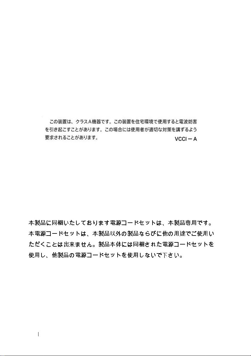
Japan VCCI compliance for class A equipment
Figure 1-8. Japan: VCCI compliance for class A equipment
This is Class A product based on the standard of the Voluntary Control
Council For Interference by Information Technology Equipment (VCCI). If
this equipment is used in a domestic environment, radio disturbance may
arise. When such trouble occurs, the user may be required to take corrective
actions.
WARNING:
Figure 1-9. Japan: warning label
Use the AC power cords with Dell EMC equipment only. Do not use Dell
EMC AC power cords with any unauthorized hardware.
India certification of compliance
The product conforms to the relevant Essential Requirements of
Telecommunication Engineering Centre (TEC) regulations.
28 Getting Started Guide
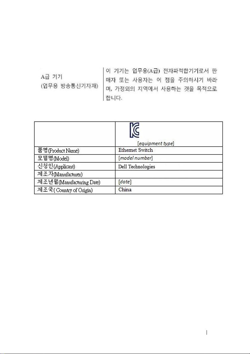
Korean certification of compliance
Figure 1-10. Korean certification of compliance
Figure 1-11. Korean package label
Safety standards and compliance agency
certifications
• IEC 62368-1, 2nd Edition
• CUS UL 60950-1, 2nd Edition
• Meets or exceeds Hi Pot and Ground Continuity testing per UL
60950-1.
• AS/NZS 60950
• CSA 60950-1-03, 2nd Edition
• EN 60950-1, 2nd Edition
• EN 60825-1, 1st Edition
• EN 60825-1 Safety of Laser Products—Part 1: Equipment Classification
Requirements and User’s Guide
Getting Started Guide 29
 Loading...