

Page 1

Dell™ PowerConnect™
6200 Series Stackable Switches
Getting Started Guide
使用入门指南
Příručka Začínáme
Guide de mise en route
Erste Schritte
Οδηγός για γρήγορο ξεκίνηµα
はじめに
시작 설명서
Instrukcja uruchomienia
Models PC6224, PC6248, PC6224P, PC6248P, and PC6224F
www.dell.com | support.dell.com
Guía de introducción
Başlangıç Kılavuzu
Page 2

Page 3

Dell™ PowerConnect™
6200 Series Stackable Switches
Getting Started Guide
Models PC6224, PC6248, PC6224P, PC6248P, and PC6224F
www.dell.com | support.dell.com
Page 4

Notes, Notices, and Cautions
NOTE: A NOTE indicates important information that helps you make better use of your computer.
NOTICE: A NOTICE indicates either potential damage to hardware or loss of data and tells you how to avoid the problem.
CAUTION: A CAUTION indicates a potential for property damage, personal injury, or death.
____________________
Information in this document is subject to change without notice.
© 2007 Dell Inc. All rights reserved.
Reproduction in any manner whatsoever without the written permission of Dell Inc. is strictly forbidden.
Trademarks used in this text: Dell, the DELL logo, and PowerConnect are trademarks of Dell Inc.; Microsoft and Windows are registered
trademarks of Microsoft Corporation.
Other trademarks and trade names may be used in this document to refer to either the entities claiming the marks and names or their products.
Dell Inc. disclaims any proprietary interest in trademarks and trade names other than its own.
Models PC6224, PC6248, PC6224P, PC6248P, and PC6224F
September 2007 P/N YC897 Rev. A02
Page 5

Contents
1 Installation
Site Preparation . . . . . . . . . . . . . . . . . . . . . . . . . . . . . . 5
Unpacking the Switch
Package Contents
Unpacking Steps
Mounting the Switch
Installing in a Rack
Installing as a Free-standing Switch
Connecting a Switch to a Terminal
Connecting a Switch to a Power Supply
Assembling a Stack
. . . . . . . . . . . . . . . . . . . . . . . . . . . 5
. . . . . . . . . . . . . . . . . . . . . . . . . . . 5
. . . . . . . . . . . . . . . . . . . . . . . . . . . 6
. . . . . . . . . . . . . . . . . . . . . . . . . . . . 6
. . . . . . . . . . . . . . . . . . . . . . . . . . 6
. . . . . . . . . . . . . . . . . . 7
. . . . . . . . . . . . . . . . . . . . . 7
. . . . . . . . . . . . . . . . . . 7
. . . . . . . . . . . . . . . . . . . . . . . . . . . . 8
2 Starting and Configuring the Switch
Connecting the Terminal to the Switch . . . . . . . . . . . . . . . . . . . 10
Booting the Switch
Initial Configuration
Initial Configuration Procedure
Example Session
. . . . . . . . . . . . . . . . . . . . . . . . . . . . 11
. . . . . . . . . . . . . . . . . . . . . . . . . . . . 12
. . . . . . . . . . . . . . . . . . . . . 12
. . . . . . . . . . . . . . . . . . . . . . . . . . . 13
Contents 3
Page 6

3 Managing a Stack
Master and Member Switches . . . . . . . . . . . . . . . . . . . . . . . 16
Stack Startup
Topology Discovery
Auto Stack ID Assignment
Firmware Version Checking
System Initialization
CLI/ Telnet/ Web Interface
Insertion and Removal of Switches
Operating as Standalone Switch
Stack ID Renumbering
User Controls
. . . . . . . . . . . . . . . . . . . . . . . . . . . . . . . 16
. . . . . . . . . . . . . . . . . . . . . . . . . . 16
. . . . . . . . . . . . . . . . . . . . . . . 16
. . . . . . . . . . . . . . . . . . . . . . 16
. . . . . . . . . . . . . . . . . . . . . . . . . . 17
. . . . . . . . . . . . . . . . . . . . . . . . . 17
. . . . . . . . . . . . . . . . . . . 17
. . . . . . . . . . . . . . . . . . . . 17
. . . . . . . . . . . . . . . . . . . . . . . . . 17
. . . . . . . . . . . . . . . . . . . . . . . . . . . . . . . 18
4 Front Panels and LEDs
Front Panels . . . . . . . . . . . . . . . . . . . . . . . . . . . . . . . . 19
LEDs
. . . . . . . . . . . . . . . . . . . . . . . . . . . . . . . . . . . 20
Systems LEDs
RJ-45 LEDs (PoE)
XFP LED
SFP LED
. . . . . . . . . . . . . . . . . . . . . . . . . . . . . 20
. . . . . . . . . . . . . . . . . . . . . . . . . . . 21
. . . . . . . . . . . . . . . . . . . . . . . . . . . . . . . 21
. . . . . . . . . . . . . . . . . . . . . . . . . . . . . . . 21
4 Contents
Page 7

Installation
This document provides basic information to install, configure, and operate Dell™ PowerConnect™ PC6224,
PC6248, PC6224P, PC6248P, and PC6224F systems. For more information, see the
available on your
updates on documentation and firmware.
User Documentation
CD, or check the Dell Support web site at
User's Guide
support.dell.com
Site Preparation
PowerConnect 6200 series switches can be mounted in a standard 48.26-cm (19-inch) rack or left freestanding
(placed on a flat surface). These switches can function as stand-alone switches. They can also be installed as a
stack of switches that function, and are managed, as a single entity.
Before installing the switch or switches, make sure that the chosen installation location meets the following site
requirements:
•
Power
— The switch is installed near an easily accessible 100–250 VAC, 50–60 Hz outlet.
•
Clearance
power connections, and ventilation.
•
Cabling
amplifiers, power lines, and fluorescent lighting fixtures.
•
Ambient
humidity of up to 95 percent, non-condensing.
— There is adequate front and rear clearance for operator access. Allow clearance for cabling,
— The cabling is routed to avoid sources of electrical noise such as radio transmitters, broadcast
— The ambient switch operating temperature range is 0 to 45ºC (32 to 113ºF) at a relative
Unpacking the Switch
, which is
for the latest
Package Contents
When unpacking each switch, make sure that the following items are included:
• One PowerConnect switch
• One AC power cable
• One RS-232 cable
• One rack-mount kit for rack installation (two mounting brackets, bolts, and cage nuts)
• One set of self-adhesive rubber pads for the free-standing switch (four pads are included)
User Documentation
•
• Getting Started Guide
• Product Information Guide
CD
Getting Started Guide 5
Page 8
Unpacking Steps
NOTE: Before unpacking the switch, inspect the container and immediately report any evidence of damage.
Place the container on a clean, flat surface and cut all straps securing the container.
1
2
Open the container or remove the container top.
3
Carefully remove the switch from the container and place it on a secure and clean surface.
4
Remove all packing material.
5
Inspect the product and accessories for damage.
Mounting the Switch
www.dell.com | support.dell.com
CAUTION: Read the safety information in the Product Information Guide as well as the safety information for other
switches that connect to or support the switch.
The AC and DC power connectors are on the back panel of the switch. We recommend connecting a redundant
power supply, such as the PowerConnect RPS-600 for non-PoE switches or the PowerConnect EPS-470 for PoE
switches.
Installing in a Rack
CAUTION: Do not use rack mounting kits to suspend the switch from under a table or desk, or attach it to a wall.
CAUTION: Disconnect all cables from the switch before continuing. Remove all self-adhesive pads from the
underside of the switch, if they have been attached.
CAUTION: When mounting multiple switches into a rack, mount the switches from the bottom up.
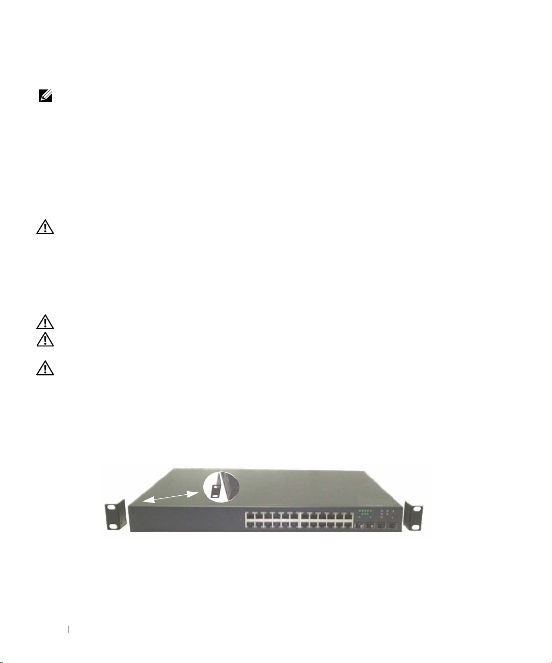
Place the supplied rack-mounting bracket on one side of the switch, ensuring that the mounting holes on
1
the switch line up to the mounting holes in the rack-mounting bracket. Figure 1-1 illustrates where to
mount the brackets.
Figure 1-1. Attaching the Brackets
2
Insert the supplied bolts into the rack-mounting holes and tighten with a screwdriver.
3
Repeat the process for the rack-mounting bracket on the other side of the switch.
6 Getting Started Guide
Page 9

4
Insert the switch into the 48.26 cm (19 inch) rack, ensuring that the rack-mounting holes on the switch line
up to the mounting holes in the rack.
5
Secure the switch to the rack with either the rack bolts or cage nuts and cage nut bolts with washers
(depending on the kind of rack you have). Fasten the bolts on bottom before fastening the bolts on top.
NOTICE: Make sure that the ventilation holes are not obstructed.
CAUTION: Make sure that the supplied rack bolts fit the pre-threaded holes in the rack.
Installing as a Free-standing Switch
NOTICE: We strongly recommend mounting the switch in a rack.
Install the switch on a flat surface if you are not installing it in a rack. The surface must be able to support
the weight of the switch and the switch cables. The switch is supplied with four self-adhesive rubber pads.
1
Attach the self-adhesive rubber pads on each location marked on the bottom of the switch.
2
Set the switch on a flat surface, and make sure that it has proper ventilation by leaving 5 cm (2 inches)
on each side and 13 cm (5 inches) at the back.
Connecting a Switch to a Terminal
1
Connect the supplied RS-232 cable to a VT100 terminal or to the serial connector of a personal computer
running VT100 terminal emulation software.
2
Connect the female DB-9 connector at the other end of the RS-232 crossover cable to the serial port
connector on the rear of the switch.
NOTE: If you are installing a stack of switches, connect the terminal to the Master Switch. This switch will light the
Master Switch LED, the top left LED in the array on the front panel. When a stack is powered up for the first time, the
switches elect the Master Switch, which may occupy any location in the stack. If you connect the terminal to a member
switch, you will not be able to use the CLI.
Connecting a Switch to a Power Supply
CAUTION: Read the safety information in the Product Information Guide as well as the safety information for other
switches that connect to or support the switch.
Connect the supplied AC power cable to the AC power connector located on the back panel.
1
Figure 1-2 illustrates where to connect the power cable.
2
To provide a redundant source of power, connect the 12 VDC power cable from a (separately purchased)
PowerConnect RPS-600 for non-PoE switches or PowerConnect EPS-470 for PoE switches to the DC power
connector located on the back panel.
NOTE: Do not connect the power cable to a grounded AC outlet at this time. Connect the switch to a power source
as described in the step detailed in "Starting and Configuring the Switch."
Getting Started Guide 7
Page 10
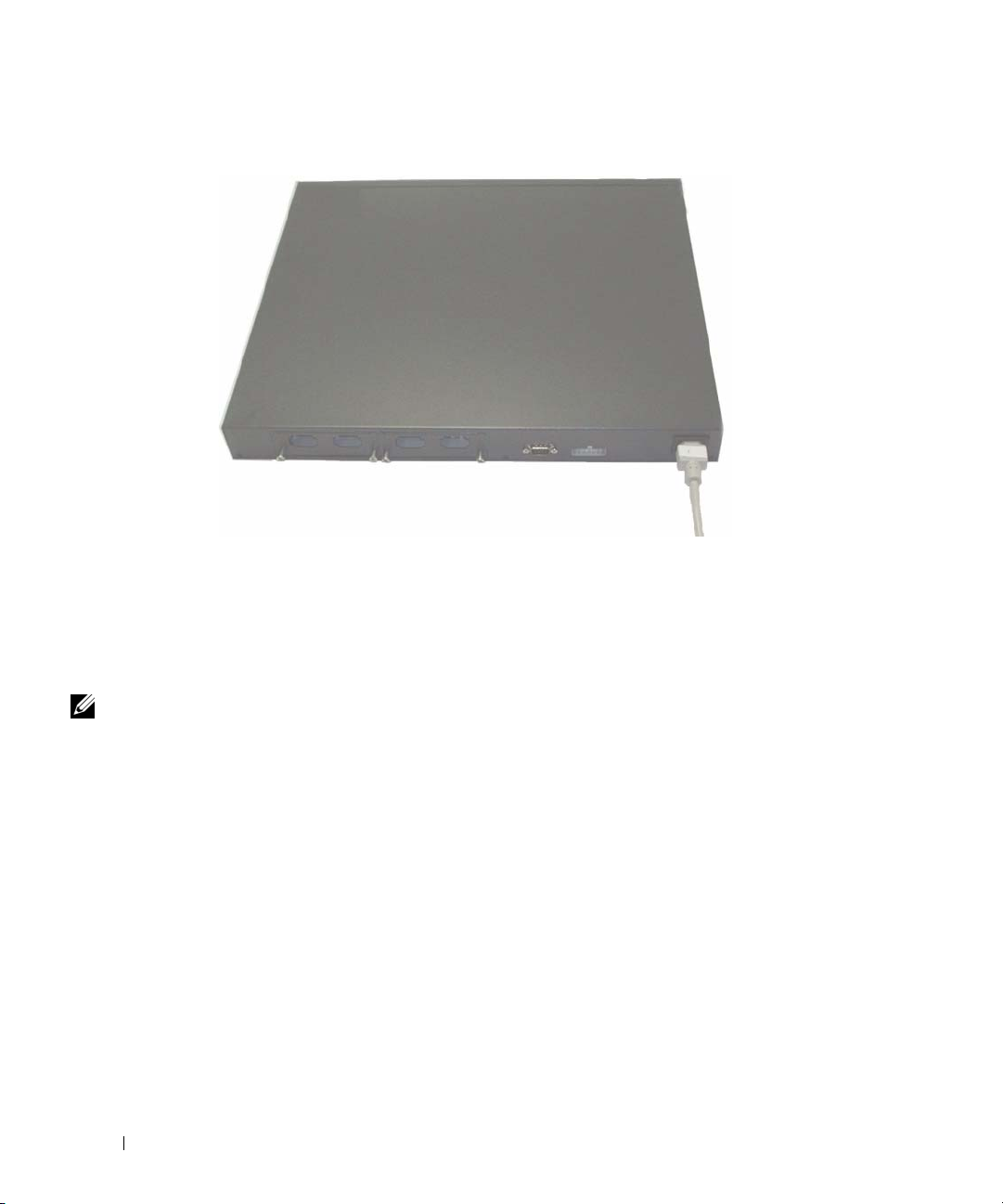
Figure 1-2. Connecting Power Cable
www.dell.com | support.dell.com
Assembling a Stack
You can stack PowerConnect 6200 series switches up to 12 switches high, supporting up to 576 front panel ports.
Create a stack by connecting adjacent units using the stacking ports on the left side of the switch rear. See
Figure 1-3.
NOTE: The switches must be turned off as they are added to a stack.
1
Install a separately purchased stacking module in rear "Bay 1" in each of the switches to be stacked.
2
Use the cables supplied with the stacking modules to connect from one switch to the next until all switches
are connected in a ring.
3
Make sure that the last stacking cable is connected from the last switch to the first switch to create a loop.
4
If necessary, use a separately purchased three-meter stacking cable to connect the switches.
8 Getting Started Guide
Page 11
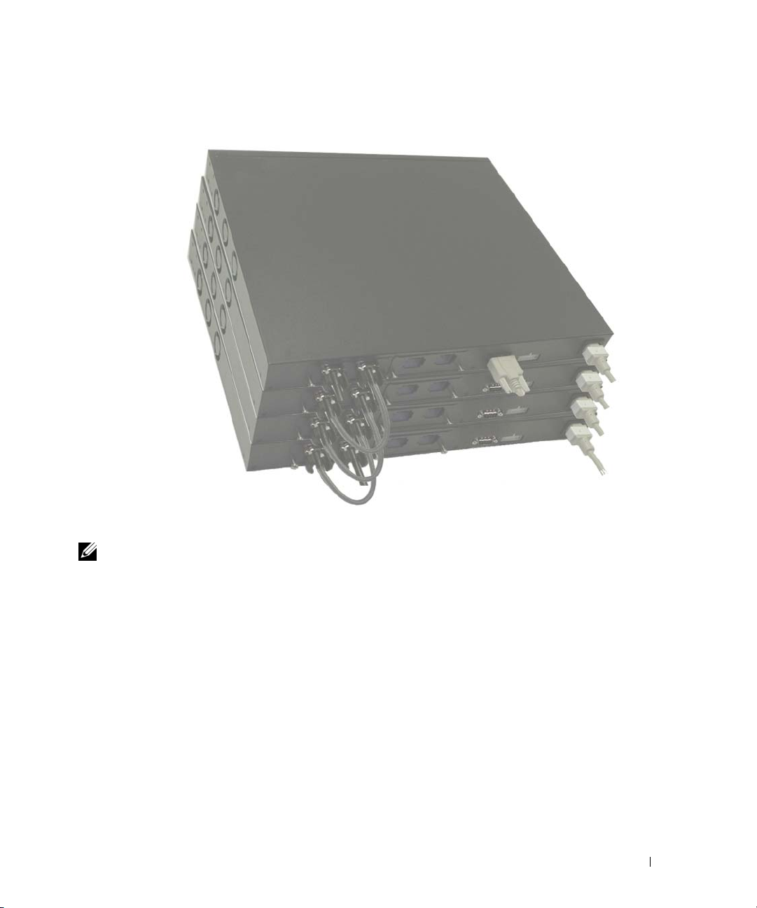
Figure 1-3. Connecting a Stack of Switches
NOTE: Long cable not shown in Figure 1-3.
The resulting ring topology allows the entire stack to function as a single switch with
capabilities.
Getting Started Guide 9
resilient fail-over
Page 12

Starting and Configuring the Switch
After completing all external connections, connect a terminal to a switch to configure the switch or stack.
Additional advanced functions are described in the
NOTE: Read the release notes for this product before proceeding. You can download the release notes from
the Dell Support website at support.dell.com.
NOTE: We recommend that you obtain the most recent version of the user documentation from the Dell Support
website at support.dell.com.
User's Guide
Connecting the Terminal to the Switch
www.dell.com | support.dell.com
To monitor and configure the switch via serial console, use the console port on the rear of the switch to connect
it to a terminal desktop system running terminal emulation software. The console port connector is a male DB-9
connector, implemented as a data terminal equipment (DTE) connector.
The following is required to use the console port:
• VT100-compatible terminal or a desktop or a portable system with a serial port, running VT100 terminal
emulation software.
• An RS-232 crossover cable with a female DB-9 connector for the console port and the appropriate
connector for the terminal.
Perform the following tasks to connect a terminal to the switch console port:
NOTE: If you are installing a stack of switches, you need to assemble and cable the stack before powering up
and configuring the stack.
Connect an RS-232 crossover cable to the terminal running VT100 terminal emulation software.
1
2
Configure the terminal emulation software as follows:
a
Select the appropriate serial port (serial port 1 or serial port 2) to connect to the console.
b
Set the data rate to 9600 baud.
c
Set the data format to 8 data bits, 1 stop bit, and no parity.
d
Set the flow control to none.
e
Set the terminal emulation mode to
f
Select Terminal keys for Function, Arrow, and Ctrl keys. Make sure that the setting is for Terminal keys
(not Microsoft
®
Windows® keys).
VT100
.
located on your
User Documentation
CD.
NOTE: When using HyperTerminal with Microsoft Windows 2000, make sure that you have Windows 2000 Service Pack
2 or later installed. With Windows 2000 Service Pack 2, the arrow keys function properly in HyperTerminal's VT100
emulation. Go to www.microsoft.com for more information on Windows 2000 service packs.
10 Getting Started Guide
Page 13
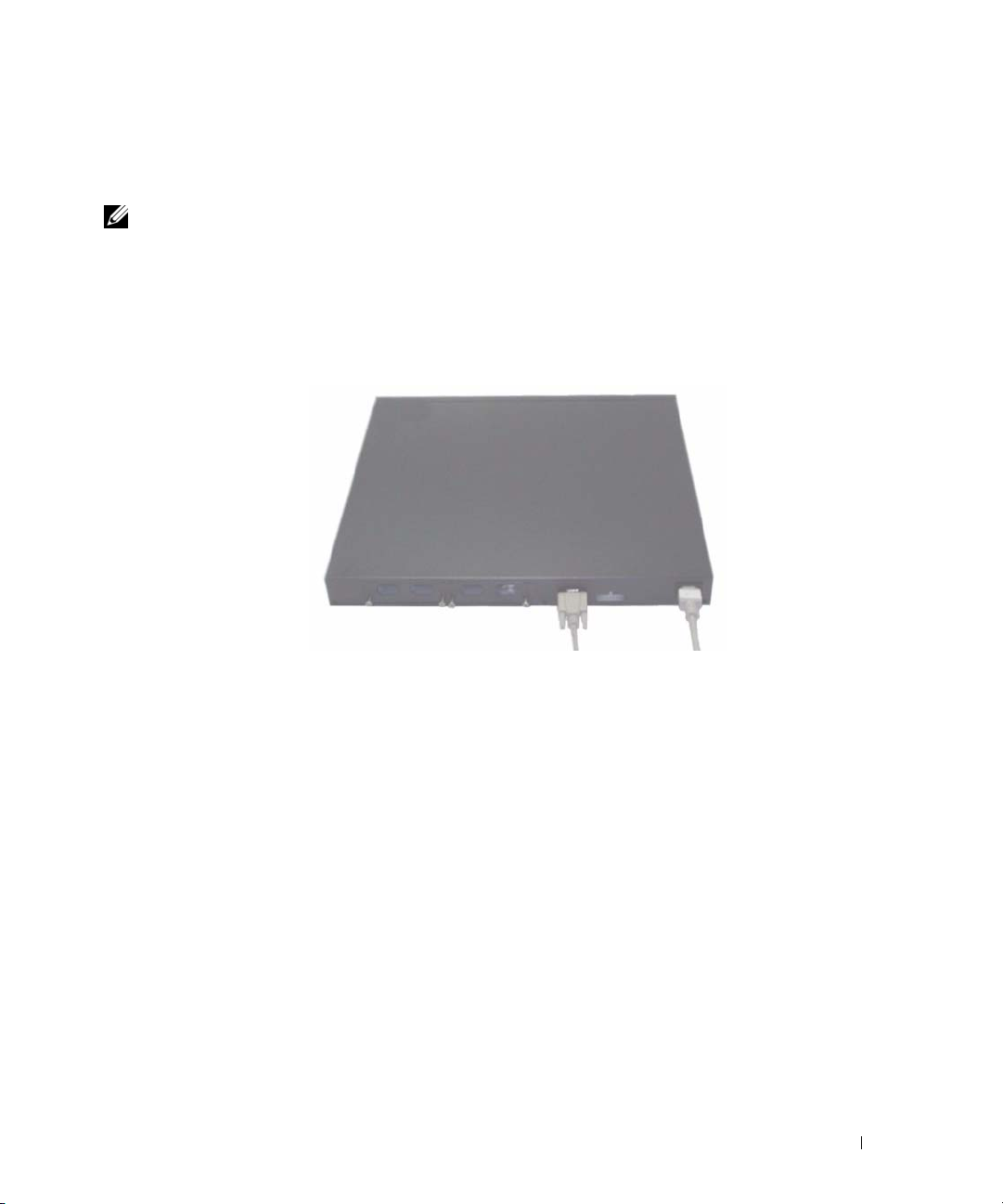
3
Connect the female connector of the RS-232 crossover cable directly to the switch console port, and
tighten the captive retaining bolts. The PowerConnect 6200 series console ports are located on the rear
panel as shown in Figure 1-4.
NOTE: If you are installing a stack of switches, connect the terminal to the Master Switch. This switch will light the
Master Switch LED, the top left LED in the array on the front panel. When a stack is powered up for the first time, the
switches elect the Master Switch, which may occupy any location in the stack. If you connect the terminal to a member
switch, you will not be able to use the CLI.
Figure 1-4. Connecting to the Console Port
Booting the Switch
1
Make sure that the switch console port is connected to a VT100 terminal or VT100 terminal emulator via
the RS-232 cable.
2
Locate an AC power receptacle.
3
Deactivate the AC power receptacle.
4
Connect the switch to the AC receptacle.
5
Activate the AC power receptacle.
When the power is turned on with the local terminal already connected, the switch goes through a power-on selftest (POST). POST runs every time the switch is initialized and checks hardware components to determine if
the switch is fully operational before completely booting. If POST detects a critical problem, the program flow
stops. If POST passes successfully, valid firmware is loaded into RAM. POST messages are displayed on the
terminal and indicate test success or failure. The boot process runs for approximately 60 seconds.
Getting Started Guide 11
Page 14

Initial Configuration
NOTE: The initial simple configuration procedure is based on the following assumptions:
• The PowerConnect switch was never configured before and is in the same state as when you received it.
• The PowerConnect switch booted successfully.
• The console connection was established and the Dell Easy Setup Wizard prompt appears on the screen
of a VT100 terminal or terminal equivalent.
The initial switch configuration is performed through the console port. After the initial configuration, you can
manage the switch either from the already-connected console port or remotely through an interface defined
during the initial configuration.
NOTE: The switch is not configured with a default user name and password.
www.dell.com | support.dell.com
NOTE: All of the settings below are necessary to allow the remote management of the switch through Telnet
(Telnet client) or HTTP (Web browser).
Before setting up the initial configuration of the switch, obtain the following information from your network
administrator:
• The IP address to be assigned to the management VLAN through which the switch is managed.
• The IP subnet mask for the network.
• The IP address of the management VLAN default gateway for configuring the default route.
Initial Configuration Procedure
You can perform the initial configuration using the Dell Easy Setup Wizard, or by using the Command Line
Interface (CLI). The Setup Wizard automatically starts when the switch configuration file is empty. You can exit
the wizard at any point by entering [ctrl+z], but all configuration settings specified will be discarded (the switch
will use the default values). For more information on CLI initial configuration see the
shows how to use the Setup Wizard for initial switch configuration. The wizard sets up the following
configuration on the switch:
• Establishes the initial privileged user account with a valid password. The wizard configures
one privileged user account during the setup.
• Enables CLI login and HTTP access to use the local authentication setting only.
• Sets up the IP address for the management VLAN.
• Sets up the SNMP community string to be used by the SNMP manager at a given IP address.
You may choose to skip this step if SNMP management is not used for this switch.
• Allows you to specify the management server IP or permit management access from all IP addresses.
• Configures the default gateway IP address.
User Guide
. This guide
12 Getting Started Guide
Page 15

Example Session
This section describes an Easy Setup Wizard session. The following values are used by the example session:
• IP address for the management VLAN is 192.168.1.100:255.255.255.0.
admin
• The user name is
, and password is
• The network management system IP address is
• The default gateway is 192.168.1.1.
• The SNMP community string to be used is
The setup wizard configures the initial values as defined above. After you complete the wizard, the switch
is configured as follows:
• SNMPv1/2c is enabled and the community string is set up as defined above. SNMPv3 is disabled
by default.
• The admin user account is set up as defined.
• A network management system is configured. From this management station, you can access the
SNMP, HTTP, and CLI interfaces. You may also choose to allow all IP addresses to access these
management interfaces by choosing the (0.0.0.0) IP address.
• An IP address is configured for the default management VLAN (1).
• A default gateway address is configured.
NOTE: In the example below, the possible user options are enclosed in [ ]. Also, where possible, the default value is
provided in { }. If you press <Enter> with no options defined, the default value is accepted. Help text is in parentheses.
The following example contains the sequence of prompts and responses associated with running an example
Dell Easy Setup Wizard session, using the input values listed above.
After the switch completes the POST and is booted, the following dialog appears:
Welcome to Dell Easy Setup Wizard
admin123.
192.168.1.10
.
Dell_Network_Manager
.
The setup wizard guides you through the initial switch configuration, and
gets you up and running as quickly as possible. You can skip the setup
wizard, and enter CLI mode to manually configure the switch. You must
respond to the next question to run the setup wizard within 60 seconds,
otherwise the system will continue with normal operation using the default
system configuration. Note: You can exit the setup wizard at any point by
entering [ctrl+z].
Would you like to run the setup wizard (you must answer this question within
60 seconds)? [Y/N] y<Enter>
Getting Started Guide 13
Page 16

Step 1:
The system is not configured for SNMP management by default. To manage the
switch using SNMP (required for Dell Open Manage Network Manager) you can:
o Set up the initial SNMP version 1 & 2 now.
o Return later and set up other SNMP accounts. (For more information
on setting up an SNMP version 3 account, see the user documentation).
Would you like to configure the SNMP management interface now? [Y/N]
y<Enter>
To configure the SNMP management account you must specify the management
system IP address and the "community string" or password that the particular
www.dell.com | support.dell.com
management system uses to access the switch. The wizard automatically
assigns the highest access level [Privilege Level 15] to this account. You
can use Dell Open Manage Network Manager or other management interfaces to
change this setting and to add additional management systems later. For more
information on adding management systems, see the User’s Guide.
To add a management station:
Please enter the SNMP community string to be used {Dell_Network_Manager}:
Dell_Network_Manager<Enter>
NOTE: If it is configured, the default access level is set to the highest available access for the SNMP management
interface. Initially only SNMPv1/2c will be activated. SNMPv3 is disabled until you return to configure security access
for SNMPv3 (e.g. engine ID, view, etc.).
Please enter the IP address of the Management System (A.B.C.D) or wildcard
(0.0.0.0) to manage from any Management Station {0.0.0.0}:
192.168.1.10<Enter>
Step 2:
Now we need to configure your initial privilege (Level 15) user account.
This account is used to login to the CLI and Web interface. You may set up
other accounts and change privilege levels later. For more information on
setting up user accounts and changing privilege levels, see the User’s
Guide.
To set up a user account:
Please enter the user name {admin}: admin<Enter>
Please enter the user password: ********<Enter>
Please reenter the user password: ********<Enter>
NOTE: If the first and second password entries are not identical, the user is prompted until they are.
NOTE: You can create additional user accounts after completing the Easy Setup Wizard. See the User’s Guide
for more information.
14 Getting Started Guide
Page 17

Step 3:
Next, an IP address is set up. The IP address is defined on the default VLAN
(VLAN #1), of which all ports are members. This is the IP address you use to
access the CLI, Web interface, or SNMP interface for the switch.
To set up an IP address:
Please enter the IP address of the device (A.B.C.D):
192.168.1.100<Enter>
Please enter the IP subnet mask (A.B.C.D or /nn):
255.255.255.0<Enter>
Step 4:
Finally, set up the gateway. Please enter the IP address of the gateway from
which this network is reachable (e.g. 192.168.1.1): 192.168.1.1<Enter>
This is the configuration information that has been collected:
SNMP Interface = "Dell_Network_Manager"@192.168.1.10
User Account set up = admin
Password = **********
Management IP address = 192.168.1.100:255.255.255.0
Gateway = 192.168.1.1
Step 5:
If the information is correct, please select (Y) to save the configuration,
and copy to the start-up configuration file. If the information is
incorrect, select (N) to discard configuration and restart the wizard: [Y/N]
y<Enter>
Thank you for using the Dell Easy Setup Wizard. You will now enter CLI mode.
Getting Started Guide 15
Page 18

Managing a Stack
Master and Member Switches
A stack of switches can be managed as a single entity when connected together. The stack can be managed
from a web-based interface, an SNMP management station, or a CLI. When a stack is created, one switch
automatically becomes the master switch. You can manually allocate an IP address to the master switch using the
console, or let DHCP do so automatically. Afterwards, you can manage the entire stack through the IP address of
the Master Switch. The Master Switch detects and reconfigures the ports with minimal operational impact in
the event of:
www.dell.com | support.dell.com
• Switch failure
• Inter-switch stacking link failure
• Switch insertion
• Switch removal
If the Master Switch goes off line, any of the Member Switches in the stack can replace it. The system will elect
a new Master Switch and reconfigure the System Configuration for the stack.
Stack Startup
Topology Discovery
When a stack is formed, a topology discovery process builds up a database that contains information about all of
the switches in the stack, including the Firmware Version, Hardware Version, Management Preference, Switch
MAC Address, and Switch Serial Number. You can use the command line interface or the Web interface to view
this information.
See the CLI Reference Manual and the User’s Guide for assistance with the CLI and Web interface, respectively.
Auto Stack ID Assignment
During the stack formation process, every switch is assigned a Stack ID. Once Stack ID assignment is complete,
each switch saves its Stack ID into the nonvolatile FLASH memory. You can use the CLI or the Web interface
to view the stack IDs.
Firmware Version Checking
Following Stack ID assignment, the Master Switch performs a consistency check to make sure that all switches
in the stack are running the same firmware version.
If the switch software versions do not match, then the ports on the member switch will not become valid for
operation. This condition is known as the Suspended Stacking Mode. You can then synchronize the firmware
on the member switch with the firmware that is running on the Master Switch.
16 Getting Started Guide
Page 19

System Initialization
If the Master Switch determines during the firmware version consistency check that all switches are running
the same version of firmware, the switch will be initialized for Stacking Mode.
System Initialization for Normal Stacking Mode
The Master Switch will initialize the stack using the last saved system configuration file. For those switches
that do not have a configuration file, the system will apply default settings to those switches.
If the configuration file is corrupted, the Master Switch will initialize the stack and set it to the Factory Default
Configuration.
You can save the configuration file. The Master Switch will automatically distribute the configuration file to
the member switches. If the Master Switch later becomes unavailable, a Member Switch can become the new
Master Switch and apply the configuration file that was saved on the original Master Switch.
System Initialization for Suspended Stacking Mode
After system initialization is complete, the Master Switch will enter Suspended Stacking Mode if the firmware
versions of the stack are inconsistent. In this mode, only the Master Switch is initialized with configuration file
information. None of the member switches are initialized. This forces all member switches to remain in nonoperational mode.
CLI/ Telnet/ Web Interface
You can use the CLI / WEB / SNMP to synchronize the firmware that is stored in the Master Switch to a member
switch.
Insertion and Removal of Switches
You can insert and remove switches to/from the current stack without cycling the power. The entire network may
be affected when a topology change occurs, as a stack reconfiguration will take place. A new Master Switch will
not be re-elected, unless the Master Switch was removed from the stack. Stack reconfiguration takes a maximum
of two minutes in a stack of twelve switches, less time for smaller stacks.
Operating as Standalone Switch
If a switch cannot detect a stacking partner on a port enabled for stacking, the switch will operate as a standalone
switch. If a stacking partner is detected, the switch will always operate in stacking mode.
Stack ID Renumbering
You can manually assign Stack IDs to a switch. A switch can only be assigned a Stack ID that has not already
been assigned to another switch in the stack. Any configuration information that was saved for the new Stack ID
is applied to the switch that is taking that Stack ID.
Getting Started Guide 17
Page 20

User Controls
Use the following CLI commands to control this feature. See the
of each command.
movemanagement
reload
member
set description
switch priority
www.dell.com | support.dell.com
switch renumber
stacking
show stack-port
show stack-port counters
show stack-port diag
show switch
show supported switchtype
CLI Reference Guide
for details on the syntax
18 Getting Started Guide
Page 21
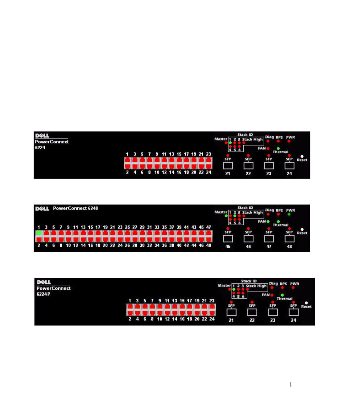
Front Panels and LEDs
This appendix describes the front panels and LEDs of the Dell PowerConnect PC6224, PC6248, PC6224P,
PC6248P, and PC6224F systems.
Front Panels
The front panels of the PowerConnect 6200 series systems are shown in the figures below.
Figure 1-1. PC 6224
Figure 1-2. PC 6248
Figure 1-3. PC 6224P
Getting Started Guide 19
Page 22

Figure 1-4. PC 6248P
Figure 1-5. PC 6224F
www.dell.com | support.dell.com
LEDs
The following sections list the LEDs.
Systems LEDs
Table 1-1. System LEDs
LED State
Fan Status
Power Supply Status
Redundant Power Supply
Diagnostic
Temperature
• Green: All Fans are operating correctly
• Red: One or more fans have failed
• Green: PS operating correctly
• Red: PS failure
• Green: Redundant supply present and operating
correctly
• Red: Redundant supply present and failed
• Off: Redundant supply is not present
• Blinking Green: Diagnostics in progress
• Solid Green: Diagnostics completed successfully
• Red: Diagnostics failed
• Green: System temperature is below threshold limit
• Red: System temperature is above threshold limit
20 Getting Started Guide
Page 23

RJ-45 LEDs (PoE)
The RJ-45 ports will have two integrated LEDs (One bi-color and one single color).
Table 1-2. RJ-45 LEDs (PoE)
LED State
Left - Single color: Port link/activity
Right (POE Model) - Dual color:
• Green: Link at 10/100/1000 Mbps
• Solid: Link but no activity
• Blinking: Link with activity
• Off: No Link
• Green: The port detects power device (PD) and
complies with the condition of the normal load
• Solid Amber: Overload or short of terminal port
or external forced voltage feeds into the port
• Blinking Amber: The total aggregated power
exceeds predefined power budget.
• Off: No PD, no power feeding
XFP LED
Table 1-3. XFP LED
LED State
Single color:
• Green Solid: Link
• Green Blinking: Activity
• Off: No Link
SFP LED
Table 1-4. SFP LED
LED State
Single color:
• Green Solid: Link
• Green Blinking: Activity
• Off: No Link
Getting Started Guide 21
Page 24

www.dell.com | support.dell.com
22 Getting Started Guide
Page 25

Dell™ PowerConnect™
6200 系列可堆叠交换机
使用入门指南
型号:
PC6224, PC6248, PC6224P, PC6248P 和 PC6224F
www.dell.com | support.dell.com
Page 26

注、注意和警告
注:注表示可以帮助您更好地使用计算机的重要信息。
注意:注意表示可能会损坏硬件或导致数据丢失,并告诉您如何避免此类问题。
警告:警告表示可能会导致财产损失、人身伤害甚至死亡。
____________________
本说明文件中的信息如有更改,恕不另行通知。
© 2007 Dell Inc.
未经
Dell Inc.
本文中使用的商标:
的注册商标。
本文件中述及的其它商标和产品名称是指拥有相应商标和名称的公司或其制造的产品。
的其它商标和产品名称不拥有任何专有权。
型号:
PC6224, PC6248, PC6224P, PC6248P 和 PC6224F
2007 年 9
版权所有,翻印必究。
书面许可,严禁以任何形式进行复制。
Dell、DELL
月
P/N YC897
徽标和
PowerConnect 是 Dell Inc.
修订版
A02
的商标;
Microsoft 和 Windows 是 Microsoft Corporation
Dell Inc.
对本公司的商标和产品名称之外
Page 27

目录
1 安装
现场准备 . . . . . . . . . . . . . . . . . . . . . . . . . . . . . . . . .
打开交换机包装
包装箱物品
打开包装步骤
安装交换机
在机架中安装
安装为自立式交换机
将交换机连接至终端
将交换机连接至电源设备
组装堆叠
. . . . . . . . . . . . . . . . . . . . . . . . . . . . .
. . . . . . . . . . . . . . . . . . . . . . . . . . . . . 27
. . . . . . . . . . . . . . . . . . . . . . . . . . . . 28
. . . . . . . . . . . . . . . . . . . . . . . . . . . . . . . .
. . . . . . . . . . . . . . . . . . . . . . . . . . . . 28
. . . . . . . . . . . . . . . . . . . . . . . . 29
. . . . . . . . . . . . . . . . . . . . . . . . . . .
. . . . . . . . . . . . . . . . . . . . . . . .
. . . . . . . . . . . . . . . . . . . . . . . . . . . . . . . . .
2 启动和配置交换机
将终端连接至交换机 . . . . . . . . . . . . . . . . . . . . . . . . . . .
引导交换机
初始配置
. . . . . . . . . . . . . . . . . . . . . . . . . . . . . . . .
. . . . . . . . . . . . . . . . . . . . . . . . . . . . . . . . .
初始配置过程
示例会话
. . . . . . . . . . . . . . . . . . . . . . . . . . . . 34
. . . . . . . . . . . . . . . . . . . . . . . . . . . . . . . 35
27
27
28
29
29
30
32
33
34
目录 25
Page 28

3 管理堆叠
主交换机和成员交换机 . . . . . . . . . . . . . . . . . . . . . . . . .
堆叠启动
CLI
用户控件
. . . . . . . . . . . . . . . . . . . . . . . . . . . . . . . .
拓扑搜索
自动堆叠 ID 分配
检查固件版本
系统初始化
/远程登录/
插入和卸下交换机
作为独立交换机运行
堆叠 ID 重新编号
. . . . . . . . . . . . . . . . . . . . . . . . . . . . . . 39
. . . . . . . . . . . . . . . . . . . . . . . . . . 39
. . . . . . . . . . . . . . . . . . . . . . . . . . . . 39
. . . . . . . . . . . . . . . . . . . . . . . . . . . . . 39
. . . . . . . . . . . . . . . . . . . . . . .
界面
Web
. . . . . . . . . . . . . . . . . . . . . . . . . 40
. . . . . . . . . . . . . . . . . . . . . . . . 40
. . . . . . . . . . . . . . . . . . . . . . . . . . 40
. . . . . . . . . . . . . . . . . . . . . . . . . . . . . . . .
4 前面板和 LED
前面板 . . . . . . . . . . . . . . . . . . . . . . . . . . . . . . . . . .
. . . . . . . . . . . . . . . . . . . . . . . . . . . . . . . . . . .
LED
系统 LED
RJ-45 LED (PoE)
XFP LED
SFP LED
. . . . . . . . . . . . . . . . . . . . . . . . . . . . . . 44
. . . . . . . . . . . . . . . . . . . . . . . . . . . 45
. . . . . . . . . . . . . . . . . . . . . . . . . . . . . . . 45
. . . . . . . . . . . . . . . . . . . . . . . . . . . . . . . 45
39
39
40
41
43
44
26 目录
Page 29

安装
本说明文件介绍有关安装、配置和操作
PC6248P
《用户指南》,或访问
更新信息。
和
PC6224F
系统的基本信息。有关详情,请参阅
Dell 支持 Web
Dell™ PowerConnect™ PC6224, PC6248, PC6224P,
CD
上的
站点
support.dell.com
User Documentation
以获取有关说明文件及固件的最新
现场准备
PowerConnect 6200
式摆放(放在平坦的平面上)。这些交换机可以作为独立的交换机使用。也可以将这些交换机
进行堆叠式安装,作为单个实体发挥作用并进行管理。
在安装一台或多台交换机之前,请确保选定的安装位置符合以下现场要求:
•
电源要求
•
空间要求
电源连接和通风的空间。
•
布线要求
电线和荧光照明装置)。
•
周围环境
非冷凝。
系列交换机既可安装在标准的
交换机应靠近易于插拔的电源插座(
—
正面及背面有足够的空间,以便操作员进行操作。请留出用于布线、
—
布线应远离电气干扰源(如无线电发送器、广播放大器、
—
交换机运行环境温度范围为
—
0 到 45C(32 到 113F
厘米(
48.26
100-250 VAC,50-60 Hz
英寸)机架中,也可以自立
19
),相对湿度最大为
)安装。
95%
,
打开交换机包装
包装箱物品
解开每个交换机的包装时,请确保其中包含以下物品:
一台
•
•
•
•
•
•
•
•
PowerConnect
一根交流电源线
一根
RS-232
一套用于机架安装的机架固定套件(两个安装支架、螺栓和锁紧螺帽)
一套用于自立式摆放交换机的自粘胶垫(包括四个垫)
User Documentation
使用入门指南
产品信息指南
交换机
电缆
CD
使用入门指南 27
Page 30

打开包装步骤
注:在打开交换机的包装之前,先检查包装盒,如有任何损坏迹象,请立即报告。
将包装盒放在整洁的平坦表面上,然后剪断固定包装盒的所有包装带。
1
2
打开包装盒或取下包装盒盖。
3
从包装盒中小心取出交换机,然后将其放在稳定且整洁的表面上。
4
取出所有包装材料。
5
检查产品及附件是否出现损坏。
安装交换机
www.dell.com | support.dell.com
警告:请阅读《产品信息指南》中的安全信息,以及连接到该交换机或支持该交换机的其它交
换机的安全信息。
交流电源连接器和直流电源连接器均位于交换机的背面板上。建议连接冗余电源设备,
PoE
交换机连接
如非
在机架中安装
警告:请勿使用机架固定套件将交换机悬挂在台面或桌面下,或固定在墙壁上。
警告:断开交换机上的所有电缆,然后继续安装。取出交换机底部的所有自粘垫(如果已粘连)。
警告:在将多台交换机安装到机架中时,请自底向上安装交换机。
1
将附带的机架固定支架放在交换机的一侧,确保交换机上的固定孔与机架固定支架上的固
定孔对齐。图
PowerConnect RPS-600 或 PoE
显示了支架的安装位置。
1-1
交换机连接
PowerConnect EPS-470
。
图
固定支架
1-1.
2
将附带的螺栓插入机架固定孔,然后用螺丝刀将其拧紧。
3
在交换机的另一侧对机架固定支架重复此过程。
4
将交换机插入
定孔。
28 使用入门指南
48.26
厘米(
英寸)机架,确保交换机上的机架固定孔对准机架上的固
19
Page 31

5
使用机架螺栓或锁紧螺帽以及带垫片的锁紧螺帽螺栓(取决于所使用的机架类型),
将交换机固定在机架上。先在底部拧紧螺栓,然后在顶部固定螺栓。
注意:确保不要堵塞通风孔。
警告:确保附带的机架螺栓插入到机架中的预制螺纹孔中。
安装为自立式交换机
注意:强烈建议您在机架中安装交换机。
如果不将交换机安装在机架中,请将其安装在平坦的表面上。该表面必须能够承受交换机以及
交换机电缆的重量。交换机附带四个自粘胶垫。
1
在交换机底部的每个标记的位置上贴上自粘胶垫。
2
将交换机放在平坦的表面上,在两侧各留出
英寸)的空间,以确保通风良好。
(
5
厘米(2 英寸)的空间,背面留出
5
13
厘米
将交换机连接至终端
1
将附带的
RS-232
计算机的串行连接器。
2
将
RS-232
注:如果安装的是交换机堆叠,请将终端连接至主交换机。该交换机将亮起主交换机 LED,
即前面板上一组 LED 中最左侧的 LED。交换机堆叠首次通电时,这些交换机将选出主交换机,
这一主交换机可能位于堆叠中的任何位置。如果将终端连接至成员交换机,将无法使用 CLI。
电缆连接至
绞接电缆另一端的
VT100
DB-9
终端,或者连接至运行
VT100
内孔连接器与交换机背面的串行端口连接器相连。
终端仿真软件的个人
将交换机连接至电源设备
警告:请阅读《产品信息指南》中的安全信息,以及连接到该交换机或支持该交换机的其它交
换机的安全信息。
将附带的交流电源线连接到背面板上的交流电源连接器。图
1
位置。
2
要提供冗余电源,请从非
PowerConnect EPS-470
(均为单独购买)中将
PoE
交换机的
PowerConnect RPS-600 或 PoE
12 VDC
电源电缆连接至背面板上
的直流电源连接器。
注:请勿在此时将电源电缆与接地的交流电源插座相连。按照“启动和配置交换机”
中详细说明的步骤将交换机连接至电源设备。
显示了连接电源电缆的
1-2
交换机的
使用入门指南 29
Page 32

图
www.dell.com | support.dell.com
1-2.
连接电源电缆
组装堆叠
以堆叠方式最多可以安装
端口。要以堆栈方式安装,请使用交换机背面左侧的堆栈端口来连接相邻的单元。
请参见图
注:在堆叠中添加交换机时必须将其关闭。
在要堆叠的每台交换机的背面 “托架 1”中安装一个单独购买的堆栈模块。
1
2
使用随堆栈模块提供的电缆依次连接每台交换机与相邻的交换机,直到将所有交换机连
接成环型。
3
请务必将最后一根堆栈电缆从最后一台交换机连接到第一台交换机,以便创建环路。
4
如果需要,请使用单独购买的三米长堆栈电缆连接交换机。
30 使用入门指南
1-3。
12 台 PowerConnect 6200
系列交换机,且支持多达
576
个前面板
Page 33

图
连接堆叠交换机
1-3.
注:图
中未显示长电缆。
1-3
所得到的环行拓扑结构使得整个堆叠可用作单台具有
灵活故障转移功能的交换机。
使用入门指南 31
Page 34

启动和配置交换机
完成所有外部连接后,将某个终端与交换机相连,以配置交换机或堆叠。
User Documentation
注:在继续操作之前,请阅读本产品的版本注释。可以从 Dell 支持 Web 站点
support.dell.com
注:建议您从 Dell 支持 Web 站点
将终端连接至交换机
上的《用户指南》中介绍了其它高级功能。
CD
下载版本注释。
support.dell.com
获取最新版本的用户说明文件。
www.dell.com | support.dell.com
运行终端仿真软件的终端台式机系统。此控制台端口连接器是一个
数据终端设备
要使用控制台端口,需要以下各项:
要通过串行控制台监测和配置交换机,请使用交换机背面的控制台端口,将交换机连接至正在
•
兼容终端,或者一台配备串行端口并运行
VT100
系统。
•
一根
RS-232
要将终端连接至交换机控制台端口,请执行以下任务:
注:如果安装的是交换机堆叠,则在通电及配置之前,需要组装堆叠并进行布线。
将
1
RS-232
2
按照以下步骤配置终端仿真软件:
a
选择适当的串行端口(串行端口
b
将数据速率设置为
c
将数据格式设置为
d
将流控制设置为
e
将终端仿真模式设置为
f
选择终端键作为功能键、箭头键和
(而不是
注意:在 Microsoft Windows 2000
或更高版本。使用
工作。有关
3
将
RS-232
PowerConnect 6200
注:如果安装的是交换机堆叠,请将终端连接至主交换机。该交换机将亮起主交换机 LED,
即前面板上一组 LED 中最左侧的 LED。交换机堆叠首次通电时,这些交换机将选出主交换机,
这一主交换机可能位于堆叠中的任何位置。如果将终端连接至成员交换机,将无法使用 CLI。
插头连接器,可用作
DB-9
(DTE)
连接器。
绞接电缆,配有适合控制台端口的
绞接电缆连接至运行
。
9600
个数据位、1 个停止位以及无奇偶校验。
8
(无)。
none
VT100
VT100
终端仿真软件的终端。
或串行端口 2)以连接至控制台。
1
。
Ctrl
Microsoft® Windows®
Windows 2000 Service Pack 2
Windows 2000 Service Pack
键)。
中使用超级终端时,请确保已安装
(服务软件包)的详情,请访问
VT100
DB-9
终端仿真软件的台式机或便携式
内孔连接器以及适合终端的连接器。
键。确保此设置适用于终端键
Windows 2000 Service Pack 2
可以确保箭头键在超级终端的
www.microsoft.com
VT100
仿真中正常
。
绞接电缆的内孔连接器直接连接至交换机控制台端口,然后拧紧紧固螺栓。
系列控制台端口位于背面板上,如图
1-4
所示。
32 使用入门指南
Page 35

图
连接至控制台端口
1-4.
引导交换机
1
确保通过
2
找到交流电源插座。
3
停用交流电源插座。
4
将交换机连接至交流插座。
5
启用交流电源插座。
RS-232
在已连接本地终端的情况下打开电源时,交换机将进行开机自测
化交换机时进行,用于检查硬件组件,以确定交换机在完全引导之前是否完全正常运转。如果
检测到严重问题,程序流将停止。如果
POST
中。
RAM
POST
电缆将交换机控制台端口连接至
VT100
终端或
VT100
终端仿真器。
(POST)。POST
成功通过,则会将一个有效的固件载入到
POST
信息显示在终端上,用于指出自测是否成功。引导过程大约运行
在每次初始
秒钟。
60
使用入门指南 33
Page 36

初始配置
注:初始简单配置步骤基于以下假设条件:
•
PowerConnect
•
PowerConnect
•
控制台连接已建立,并且
的屏幕上。
应通过控制台端口执行初始交换机配置。完成初始配置后,既可以通过已连接的控制台端口管
理交换机,也可以通过在初始配置过程中定义的接口对交换机进行远程管理。
注:交换机未配置默认的用户名和密码。
www.dell.com | support.dell.com
注:要通过远程登录(远程登录客户端)或 HTTP(Web 浏览器)来远程管理交换机,
需要以下所有设置。
在设置交换机的初始配置之前,从网络管理员处获得以下信息:
•
要分配给管理
•
网络的
IP
•
用于配置默认路由的管理
初始配置过程
可以使用
将自动启动该安装向导。可以随时通过输入
弃(交换机将使用默认值)。有关
如何使用该安装向导来进行初始交换机配置。该向导设置交换机的以下配置:
Dell
•
建立拥有权限的初始用户帐户以及有效的密码。在安装过程中,该向导将配置一个具
有权限的用户帐户。
•
启用
•
设置管理
•
设置
使用
•
允许指定管理服务器
•
配置默认网关
交换机此前从未进行过任何配置,其状态与收到时相同。
交换机引导成功。
简易安装向导提示信息显示在
Dell
VLAN 的 IP
子网掩码。
简易安装向导或命令行界面
登录和
CLI
VLAN 的 IP
SNMP
SNMP
管理器要使用的
管理,则可以选择跳过这一步。
IP
地址,系统将通过该
VLAN
HTTP
IP
地址。
默认网关的
CLI
访问,以便仅使用本地验证设置。
地址。
SNMP
,或允许从所有
初始配置的详情,请参阅《用户指南》。该指南说明了
VLAN
地址。
IP
来进行初始配置。当交换机配置文件为空时,
(CLI)
[ctrl+z]
团体字符串(给定了
退出向导,但指定的所有配置设置将被丢
地址中进行管理访问。
IP
对交换机进行管理。
VT100
IP
终端或对应终端设备
地址)。如果该交换机不
34 使用入门指南
Page 37

示例会话
本节介绍了一个简易安装向导会话。示例会话将使用以下值:
•
管理
VLAN 的 IP
•
用户名为
•
网络管理系统
•
默认网关为
•
要使用的
admin
SNMP
安装向导根据上述定义的方式配置初始值。向导完成后,按照以下方式配置交换机:
•
启用
SNMPv1/2c
SNMPv3
•
根据定义的方式设置
•
配置网络管理系统。从该管理站,可以访问
通过选择
•
为默认管理
•
配置默认网关地址。
注:在以下示例中,可能的用户选项包括在 [ ] 中。另外,可能时,{ } 将提供默认值。如果未定
义选项,按 <Enter> 键将接受默认值。帮助文本在括号中。
处于禁用状态。
(0.0.0.0) IP
地址为
,密码为
地址为
IP
192.168.1.1
团体字符串为
192.168.1.100:255.255.255.0
admin123
192.168.1.10
。
。
。
Dell_Network_Manager
。
。
,并按上述定义的方式设置团体字符串。默认情况下,
admin
用户帐户。
SNMP、HTTP 及 CLI
VLAN (1)
地址,还可以选择允许所有
配置
IP
地址。
地址访问这些管理界面。
IP
界面。
以下示例包含与使用上面列出的输入值运行
交换机完成
并引导后,将显示以下对话信息:
POST
简易安装向导示例会话相关的提示序列和响应。
Dell
Welcome to Dell Easy Setup Wizard(欢迎使用 Dell 简易安装向导)
The setup wizard guides you through the initial switch
configuration, and gets you up and running as quickly as possible.
You can skip the setup wizard, and enter CLI mode to manually
configure the switch. You must respond to the next question to run
the setup wizard within 60 seconds, otherwise the system will
continue with normal operation using the default system
configuration. Note: You can exit the setup wizard at any point by
entering [ctrl+z].(该安装向导将指导您完成初始交换机配置,并尽快使您开机并运
行。可以跳过安装向导,进行 CLI 模式以手动配置交换机。您必须在 60 秒之内答复下
一个问题才能运行安装向导,否则系统将使用默认的系统配置继续正常运行。注:可以随
时通过输入 [ctrl+z] 键退出安装向导。)
Would you like to run the setup wizard (you must answer this question
within 60 seconds)?(是否要运行安装向导 [必须在 60 秒内回答该问题 ]?)
[Y/N](是/否)y(是)<Enter>
使用入门指南 35
Page 38

步骤 1:
The system is not configured for SNMP management by default. To
manage the switch using SNMP (required for Dell Open Manage Network
Manager) you can:(默认情况下,系统未配置为使用 SNMP 管理。要使用 SNMP
管理交换机 [Dell Open Manage Network Manager 要求],您可以:)
o Set up the initial SNMP version 1 & 2 now.
(立即设置初始 SNMP 版本 1 和 2。)
o Return later and set up other SNMP accounts. (For more information
on setting up an SNMP version 3 account, see the user
documentation).(稍后返回,然后设置其它 SNMP 帐户。
www.dell.com | support.dell.com
有关设置 SNMP 版本 3 帐户的详情,请参阅用户说明文件)。
Would you like to configure the SNMP management interface now?
(是否立即配置 SNMP 管理界面?) [Y/N](是/否)y(是)<Enter>
To configure the SNMP management account you must specify the
management system IP address and the "community string" or
password that the particular management system uses to access the
switch. The wizard automatically assigns the highest access level
[Privilege Level 15] to this account. You can use Dell Open Manage
Network Manager or other management interfaces to change this
setting and to add additional management systems later. For more
information on adding management systems, see the User’s Guide.
(要配置 SNMP 管理帐户,必须指定管理系统 IP 地址,以及“团体字符串”或特定管理系
统用于访问交换机的密码。该向导将自动为此帐户分配最高级别的访问权限 [权限级别
15]。可以使用 Dell Open Manage Network Manager 或其它管理界面更改这一设
置,并且稍后添加其它管理系统。有关添加管理系统的详细信息,请参阅《用户指南》。)
To add a management station:(要添加管理站:)
Please enter the SNMP community string to be used
{Dell_Network_Manager}:(请输入要使用的
{Dell_Network_Manager}:)
Dell_Network_Manager<Enter>
注:如果已配置,默认访问级别将设置为用于访问 SNMP 管理界面的最高权限级别。
最初将仅激活 SNMPv1/2c。将禁用 SNMPv3,直至返回而为 SNMPv3 配置安全访问
(例如引擎 ID,查看等)。
Please enter the IP address of the Management System (A.B.C.D)
or wildcard (0.0.0.0) to manage from any Management Station
{0.0.0.0}:(请输入管理系统的 IP 地址 [A.B.C.D] 或通配符 [0.0.0.0]
以便从任何管理站 {0.0.0.0} 进行管理:)
192.168.1.10<Enter>
36 使用入门指南
SNMP 团体字符串
Page 39

步骤 2:
Now we need to configure your initial privilege (Level 15) user
account. This account is used to login to the CLI and Web
interface. You may set up other accounts and change privilege
levels later. For more information on setting up user accounts and
changing privilege levels, see the User’s Guide.(现在,需要配置初始权
限 [ 级别 15] 用户帐户。该帐户用于登录到 CLI 界面及 Web 界面。稍后,可以设置其
它帐户并更改权限级别。有关设置用户帐户和更改权限级别的详情,请参阅《用户指南》。)
To set up a user account:(要设置用户帐户:)
Please enter the user name {admin}:(请输入用户名 {admin}:)
admin<Enter>
Please enter the user password:(请输入用户密码:)********<Enter>
Please reenter the user password:
注:如果第一次和第二次输入的密码不相同,系统将提示用户直至密码相同为止。
注:简易安装向导完成后,可以创建其它用户帐户。有关详情,请参阅《用户指南》。
(请重新输入用户密码:)
********<Enter>
步骤 3:
Next, an IP address is set up. The IP address is defined on the
default VLAN (VLAN #1), of which all ports are members. This is the
IP address you use to access the CLI, Web interface, or SNMP
interface for the switch.(接下来,设置 IP 地址。在默认的 VLAN (VLAN #1)
上定义 IP 地址,其中的所有端口均是成员。对于交换机,这是用于访问 CLI 界面、
Web 界面或 SNMP 界面的 IP 地址。)
To set up an IP address:(要设置 IP 地址:)
Please enter the IP address of the device (A.B.C.D):
(请输入设备的 IP 地址 [A.B.C.D]:)
192.168.1.100<Enter>
Please enter the IP subnet mask (A.B.C.D or /nn):
(请输入 IP 子网掩码 [A.B.C.D 或 /nn]:)
255.255.255.0<Enter>
使用入门指南 37
Page 40

步骤 4:
Finally, set up the gateway. Please enter the IP address of the
gateway from which this network is reachable (e.g. 192.168.1.1):
(最后,设置网关。请输入通过它可访问网络的网关的 IP 地址
[ 例如,192.168.1.1]:) 192.168.1.1<Enter>
This is the configuration information that has been collected:
(以下是已收集的配置信息:)
SNMP Interface = "Dell_Network_Manager"@192.168.1.10
(SNMP 界面 = "Dell_Network_Manager"@192.168.1.10)
User Account set up = admin(用户帐户设置 = admin)
www.dell.com | support.dell.com
Password = **********(密码 = **********)
Management IP address = 192.168.1.100:255.255.255.0
(管理 IP 地址 = 192.168.1.100:255.255.255.0)
Gateway = 192.168.1.1(网关 = 192.168.1.1)
步骤 5:
If the information is correct, please select (Y) to save the
configuration, and copy to the start-up configuration file. If the
information is incorrect, select (N) to discard configuration and
restart the wizard:(如果信息正确,请选择 (Y) 保存配置,并将其复制到启动配
置文件。如果信息不正确,请选择 (N) 丢弃配置,然后重新启动向导:) [Y/N]
(是/否)y(是)<Enter>
Thank you for using the Dell Easy Setup Wizard. You will now enter
CLI mode.(感谢您使用 Dell 简易安装向导。现在您将进入 CLI 模式。)
38 使用入门指南
Page 41

管理堆叠
主交换机和成员交换机
当交换机连接在一起时,交换机堆叠可以作为单个实体进行管理。可以通过基于
管理站或
SNMP
用控制台为主交换机手动分配
机的
地降低对运行造成的影响:
如果主交换机脱机,堆叠中的任何成员交换机均可取而代之。系统将选择新的主交换机,
并为堆叠重新配置系统配置。
地址管理整个堆叠。在以下情况下,主交换机将检测端口并对其重新配置,以最大限度
IP
•
交换机故障
•
交换机间堆叠链路故障
•
插入交换机
•
卸下交换机
来管理堆叠。创建堆叠后,其中一台交换机将自动成为主交换机。可以使
CLI
地址,或使
IP
DHCP
自动执行此操作。然后,可以通过主交换
Web
的界面、
堆叠启动
拓扑搜索
组成堆叠后,拓扑搜索过程将构建一个数据库,其中包含有关堆叠中所有交换机的信息,
包括固件版本、硬件版本、管理首选项、交换机
使用命令行界面或
注:有关 CLI 和 Web 界面的帮助,请分别参阅 CLI 参考手册和 《用户指南》。
自动堆叠
在堆叠形成过程中,会给每台交换机分配一个堆叠
其堆叠
分配
ID
保存到非易失性
ID
界面可查看此信息。
Web
FLASH
存储器中。
使用
地址和交换机序列号等。
MAC
。完成堆叠
ID
CLI 或 Web
ID
界面可查看堆栈
分配后,每台交换机都将
。
ID
检查固件版本
在分配堆叠
相同的固件版本。
如果交换机软件版本不匹配,成员交换机上的端口将无法有效工作。这种情况称为暂挂
堆叠模式。然后,可以使用主交换机上运行的固件来同步成员交换机上的固件。
之后,主交换机将执行一致性检查,以确保堆叠中的所有交换机正在运行
ID
系统初始化
在固件版本一致性检查期间,如果主交换机确定所有交换机都运行相同的固件版本,
则该交换机将初始化为堆叠模式。
使用入门指南 39
Page 42

系统初始化为正常堆叠模式
主交换机将使用上一次保存的系统配置文件来对堆叠进行初始化。对于不具备配置文件的那些
交换机,系统将对它们应用默认设置。
如果配置文件已损坏,主交换机将对堆叠进行初始化,并将其设置为出厂默认配置。
您可以保存该配置文件。主交换机将自动为成员交换机分配配置文件。如果稍后主交换机变
得无法使用,某台成员交换机可以成为新的主交换机,并应用在原来的主交换机上保存的配
置文件。
系统初始化为暂挂堆叠模式
系统初始化完成后,如果堆叠的固件版本不一致,主交换机将进入暂挂堆叠模式。在此模式
www.dell.com | support.dell.com
下,仅使用配置文件信息对主交换机进行初始化。而不对任何成员交换机进行初始化。
这将强制所有成员交换机保持为非操作模式(默认情况下,禁用所有端口)。
/远程登录/
CLI
可以使用
CLI / WEB / SNMP
Web
,使主交换机中存储的固件与成员交换机中的固件同步。
界面
插入和卸下交换机
可以向当前堆叠中插入交换机或从当前堆叠中卸下交换机,而无需关闭电源然后再次打开。
拓扑发生变化时,将发生堆叠重新配置,整个网络可能会受到影响。除非从堆叠中卸下主交换
机,否则不用重新选择新的主交换机。在由
多需要
分钟,对于较小的堆叠,需要的时间要少一些。
2
台交换机组成的堆叠中,堆叠重新配置过程最
12
作为独立交换机运行
如果某台交换机在用于堆叠的端口上检测不到堆叠伙伴,则该交换机将作为独立的交换机运行。
如果检测到堆叠伙伴,该交换机始终在堆叠模式下运行。
堆叠
可以手动为交换机分配堆叠
给堆叠中的其它交换机。为新堆叠
重新编号
ID
。一台交换机只能分配一个堆叠
ID
保存的任何配置信息将应用到获得该堆叠
ID
,而且该堆叠
ID
尚未分配
ID
的交换机。
ID
40 使用入门指南
Page 43

用户控件
使用以下
movemanagement
reload
member
set description
switch priority
switch renumber
stacking
show stack-port
show stack-port counters
show stack-port diag
show switch
show supported switchtype
命令控制这一功能。有关每个命令的语法的详情,请参阅《
CLI
参考指南》。
CLI
使用入门指南 41
Page 44

www.dell.com | support.dell.com
42 使用入门指南
Page 45

前面板和
LED
本附录介绍
LED
Dell PowerConnect PC6224、PC6248、PC6224P、PC6248P 和 PC6224F
。
前面板
PowerConnect 6200
图
1-1. PC 6224
图
1-2. PC 6248
系列系统的前面板如下图所示。
系统的前面板和
图
1-3. PC 6224P
使用入门指南 43
Page 46

图
1-4. PC 6248P
图
1-5. PC 6224F
www.dell.com | support.dell.com
LED
以下各节列出了
系统
LED
表
LED
风扇状态
电源设备状态
冗余电源设备
诊断程序
温度
1-1.
系统
LED
LED
。
状态
•
绿色:所有风扇工作正常
•
红色:一个或多个风扇出现故障
•
绿色:电源设备工作正常
•
红色:电源设备出现故障
•
绿色:冗余电源设备存在且工作正常
•
红色:冗余电源设备存在但出现故障
•
不亮:无冗余电源设备
•
呈绿色闪烁:诊断程序正在运行中
•
呈绿色稳定亮起:已成功完成诊断程序
•
红色:诊断程序失败
•
绿色:系统温度低于阈值限制
•
红色:系统温度高于阈值限制
44 使用入门指南
Page 47

RJ-45 LED (PoE)
端口有两个组合的
RJ-45
表
1-2. RJ-45 LED (PoE)
(一个双色和一个单色)。
LED
LED
左
单色:端口链路/活动
-
右(
模式)- 双色:
POE
XFP LED
表
1-3. XFP LED
LED
单色:
状态
•
绿色:
10/100/1000 Mbps
•
稳定亮起:链路连通但链路上没有活动
•
闪烁:链路连通并且有活动
•
不亮:链路未连通
•
绿色:端口检测到电源设备
常负荷条件
•
呈琥珀色稳定亮起:超负荷、终端端口短路
或外加电压输入端口
•
呈琥珀色闪烁:合计总功率超过预定义的功
率预计值。
•
不亮:无电源设备、无电源输入
状态
•
呈绿色稳定亮起:链路连通
•
呈绿色闪烁:活动
•
不亮:链路未连通
链路
(PD)
并且符合正
SFP LED
表
1-4. SFP LED
LED
单色:
状态
•
呈绿色稳定亮起:链路连通
•
呈绿色闪烁:活动
•
不亮:链路未连通
使用入门指南 45
Page 48

www.dell.com | support.dell.com
46 使用入门指南
Page 49

Dell™ PowerConnect™
Stohovatelné přepínače
řady 6200
Příručka Začínáme
Modely PC6224, PC6248, PC6224P, PC6248P a PC6224F
www.dell.com | support.dell.com
Page 50

Poznámky, upozornění a výstrahy
POZNÁMKA: POZNÁMKA označuje důležitou informaci, s jejíž pomocí lépe využijete svůj počítač.
UPOZORNĚNÍ: UPOZORNĚNÍ označuje hrozící nebezpečí poškození hardwaru nebo ztráty dat a radí,
jak problému předejít.
POZOR: Výstraha („POZOR“) poukazuje na riziko poškození majetku, poranění nebo smrtelného
úrazu.
____________________
Informace obsažené v tomto dokumentu podléhají změnám bez předchozího upozornění.
© 2007 Dell Inc. Všechna práva vyhrazena.
Jakákoli reprodukce tohoto dokumentu je bez písemného souhlasu společnosti Dell Inc. přísně zakázána.
Ochranné známky použité v tomto textu: Dell, logo DELL a PowerConnect jsou ochranné známky společnosti Dell Inc.;
Microsoft a Windows jsou registrované ochranné známky společnosti Microsoft.
V tomto dokumentu mohou být použity další ochranné známky a obchodní názvy odkazující na subjekty, kterým tyto známky či názvy patří,
nebo na jejich výrobky. Společnost Dell Inc. se zříká jakýchkoli vlastnických zájmů o jiné než vlastní ochranné známky a obchodní názvy.
Modely PC6224, PC6248, PC6224P, PC6248P a PC6224F
Září 2007 P/N YC897 Rev. A02
Page 51

Obsah
1 Instalace
Příprava místa . . . . . . . . . . . . . . . . . . . . . . . . . . . . . 51
Rozbalení přepínače
Obsah balení
Postup rozbalení
Montáž přepínače
Instalace do stojanu
Instalace volně instalovaného přepínače
Připojení přepínače k terminálu
Připojení přepínače k napájecímu zdroji
Stohování
. . . . . . . . . . . . . . . . . . . . . . . . . . . . . . . . 55
. . . . . . . . . . . . . . . . . . . . . . . . . . 51
. . . . . . . . . . . . . . . . . . . . . . . . . . . . 51
. . . . . . . . . . . . . . . . . . . . . . . . . . 52
. . . . . . . . . . . . . . . . . . . . . . . . . . . . 52
. . . . . . . . . . . . . . . . . . . . . . . . . 52
. . . . . . . . . . . . . . 53
. . . . . . . . . . . . . . . . . . . . 53
. . . . . . . . . . . . . . . 54
2 Spuštění a konfigurace přepínače
Připojení terminálu k přepínači . . . . . . . . . . . . . . . . . . . . 56
Bootování přepínače
Počáteční konfigurace
Postup počáteční konfigurace
Příklad relace
. . . . . . . . . . . . . . . . . . . . . . . . . . 58
. . . . . . . . . . . . . . . . . . . . . . . . . 58
. . . . . . . . . . . . . . . . . . . 59
. . . . . . . . . . . . . . . . . . . . . . . . . . . . 59
Obsah 49
Page 52

3 Správa stohu
Přepínač Master a členské přepínače. . . . . . . . . . . . . . . . . 63
Spuštění stohu
Zjištění topologie
Automatické přidělení Stack ID
Kontrola verze firmwaru
Inicializace systému
Rozhraní příkazového řádku, Telnet a webové rozhraní
Vložení a odebrání přepínačů
Provoz samostatného přepínače
Přečíslování Stack ID
Uživatelské příkazy
. . . . . . . . . . . . . . . . . . . . . . . . . . . . . 63
. . . . . . . . . . . . . . . . . . . . . . . . . . 63
. . . . . . . . . . . . . . . . . . . 63
. . . . . . . . . . . . . . . . . . . . . . . 64
. . . . . . . . . . . . . . . . . . . . . . . . . 64
. . . . . . 65
. . . . . . . . . . . . . . . . . . . 65
. . . . . . . . . . . . . . . . . . 65
. . . . . . . . . . . . . . . . . . . . . . . . 65
. . . . . . . . . . . . . . . . . . . . . . . . . . . 65
4 Čelní panely a indikátory LED
Čelní panely . . . . . . . . . . . . . . . . . . . . . . . . . . . . . . . 67
Indikátory LED
Indikátory LED systémů
Indikátory LED RJ-45 (PoE)
Indikátor LED XFP
Indikátor LED SFP
. . . . . . . . . . . . . . . . . . . . . . . . . . . . . 68
. . . . . . . . . . . . . . . . . . . . . . . 68
. . . . . . . . . . . . . . . . . . . . 69
. . . . . . . . . . . . . . . . . . . . . . . . . 69
. . . . . . . . . . . . . . . . . . . . . . . . . 69
50 Obsah
Page 53

Instalace
V tomto dokumentu jsou shrnuty základní informace k instalaci, konfiguraci a provozu systémů
Dell™ PowerConnect™ PC6224, PC6248, PC6224P, PC6248P a PC6224F. Další informace viz
Příručka uživatele
nebo navštivte webovou stránku technické podpory společnosti Dell na adrese
kde najdete nejnovější verze dokumentace a firmwaru.
Příprava místa
Přepínače řady PowerConnect 6200 lze instalovat do standardního stojanu 48,26 cm (19 palců), nebo
je lze instalovat volně (položit na rovnou plochu). Tyto přepínače mohou pracovat jako samostatné
přepínače. Přepínače lze také instalovat do stohu přepínačů, který potom pracuje a je spravován jako
jeden celek.
Před zahájením instalace přepínače nebo přepínačů zkontrolujte, že instalační místo splňuje
následující podmínky:
•
Napájení
100 - 250 VAC, 50 - 60 Hz.
•
Volný prostor
Ponechte místo pro kabeláž, elektrická vedení a ventilaci.
•
Kabeláž
reproduktory, elektrická vedení a fluorescenční osvětlení.
•
Okolní prostředí
při relativní vlhkosti vzduchu do 95 procent, bez kondenzace.
, která je k dispozici na disku CD
— Přepínač je instalován v blízkosti snadno dostupné elektrické zásuvky
— Z čela přepínače i za ním je k dispozici dostatečný prostor pro přístup obsluhy.
— Kabely jsou vedeny mimo zdroje elektrického šumu, jako jsou radiové vysílače,
— Rozsah okolní provozní teploty přepínače je 0 až 45°C (32 až 113°F)
User Documentation
s dokumentací pro uživatele,
support.dell.com
,
Rozbalení přepínače
Obsah balení
Po rozbalení každého přepínače zkontrolujte, že balení obsahuje následující položky:
•
jeden přepínač PowerConnect,
•
jeden napájecí kabel pro střídavé napětí,
•
jeden kabel RS-232,
•
jedna montážní sada pro instalaci do stojanu (dvě montážní konzoly, šrouby a klecové matice),
•
jedna sada samolepicích pryžových podložek pro volně instalovaný přepínač (čtyři podložky),
•
disk CD s
•
příručka Začínáme
•
Informační příručka produktu
dokumentací pro uživatele
,
Příručka Začínáme 51
Page 54

Postup rozbalení
POZNÁMKA: Před vlastním rozbalením přepínače zkontrolujte krabici a ihned oznamte
všechna případná poškození.
1
Krabici umístěte na čistý a plochý povrch a přestřihněte všechny pásky, které ji zabezpečují.
2
Otevřete krabici nebo sejměte její vrchní díl.
3
Opatrně vyjměte přepínač z krabice a položte ho na pevný a čistý povrch.
4
Odstraňte veškerý obalový materiál.
5
Zkontrolujte výrobek a příslušenství, zda nejsou poškozené.
www.dell.com | support.dell.com
Montáž přepínače
POZOR: Přečtěte si bezpečnostní informace obsažené v Informační příručce produktu
a také bezpečnostní informace k ostatním přepínačům, které jsou k přepínači připojené
nebo na kterých je přepínač umístěný.
Konektory střídavého a stejnosměrného napájení jsou umístěny na zadním panelu přepínače.
Doporučujeme připojit záložní napájecí zdroj, například PowerConnect RPS-600 pro jiné přepínače
než PoE nebo PowerConnect EPS-470 pro přepínače PoE.
Instalace do stojanu
POZOR: Sadu pro montáž do stojanu nepoužívejte k zavěšení přepínače pod stůl
ani k instalaci na zeď.
POZOR: Než budete v instalaci pokračovat, odpojte od přepínače všechny kabely.
Ze spodní strany přepínače odstraňte samolepicí podložky, jestliže byly použity.
POZOR: Jestliže do stojanu instalujete více přepínačů, instalujte přepínače ode
dna stojanu směrem nahoru.
1
Umístěte dodanou konzolu pro montáž do stojanu k jedné straně přepínače tak, aby montážní
otvory na přepínači lícovaly s montážními otvory v konzole. Obr. 1-1 znázorňuje místa
připevnění konzol.
Obr. 1-1. Připevnění konzol
52 Příručka Začínáme
Page 55

2
Vložte dodané šrouby do montážních otvorů a utáhněte je šroubovákem.
3
Postup zopakujte u konzoly na opačné straně přepínače.
4
Zasuňte přepínač do stojanu 48,26 cm (19 palců) tak, aby montážní otvory na přepínači
lícovaly s montážními otvory ve stojanu.
5
Připevněte přepínač do stojanu šrouby nebo klecovými maticemi a šrouby s podložkou
(v závislosti na typu použité stojanové skříně). Dotáhněte nejprve spodní šrouby, potom
vrchní šrouby.
UPOZORNĚNÍ: Zkontrolujte, že ventilační otvory jsou volné.
POZOR: Zkontrolujte, že dodané šrouby jsou vhodné pro závitové otvory ve stojanu.
Instalace volně instalovaného přepínače
UPOZORNĚNÍ: Důrazně doporučujeme instalovat přepínač do stojanu.
Přepínač instalujte na rovný povrch, jestliže jste se nerozhodli pro jeho instalaci do stojanu. Povrch
musí unést hmotnost přepínače a příslušných kabelů. Přepínač je dodán se čtyřmi samolepicími
pryžovými podložkami.
1
Tyto pryžové podložky nalepte na označená místa na spodní straně přepínače.
2
Položte přepínač na rovný povrch a zkontrolujte, že je zajištěno řádné odvětrání - na každé straně
přepínače ponechte 5 cm, vzadu pak 13 cm volného prostoru.
Připojení přepínače k terminálu
1
Připojte dodaný kabel RS-232 do terminálu VT100 nebo k sériovému portu osobního počítače,
ve kterém je spuštěn emulační software terminálu VT100.
2
Zásuvkový konektor DB-9 na druhém konci kříženého kabelu RS-232 připojte do sériového
portu na zadní straně přepínače.
POZNÁMKA: Jestliže instalujete stoh přepínačů, připojte terminál k přepínači Master.
Na tomto přepínači se rozsvítí kontrolka LED přepínače Master, horní levá kontrolka LED
na čelním panelu. Při prvním připojení stohu ke zdroji napětí zvolí přepínače přepínač Master,
který může v rámci stohu obsadit kteroukoli pozici. Jestliže připojíte terminál k členskému
přepínači, nebudete moci používat rozhraní příkazového řádku (CLI).
Příručka Začínáme 53
Page 56

Připojení přepínače k napájecímu zdroji
POZOR: Přečtěte si bezpečnostní informace obsažené v Informační příručce produktu
a také bezpečnostní informace k ostatním přepínačům, které jsou k přepínači připojené
nebo na kterých je přepínač umístěný.
1
Připojte dodaný napájecí kabel do napájecího konektoru střídavého napětí, který je umístěn
na zadním panelu. Obr. 1-2 znázorňuje místo připojení napájecího kabelu.
2
Chcete-li připojit také záložní napájecí zdroj, připojte napájecí kabel 12 VDC ze zdroje
PowerConnect RPS-600 pro jiné přepínače než PoE nebo PowerConnect EPS-470 pro přepínače
PoE (zakoupený zvlášt’) do napájecího konektoru stejnosměrného napětí na zadním panelu.
POZNÁMKA: V tomto okamžiku ještě nezapojujte napájecí kabel do uzemněné zásuvky
www.dell.com | support.dell.com
střídavého napětí. Přepínač připojte ke zdroji napájení tak, jak je podrobně popsáno v kroku
Spuštění a konfigurace přepínače.
Obr. 1-2. Připojení napájecího kabelu
54 Příručka Začínáme
Page 57

Stohování
Přepínače PowerConnect 6200 series můžete integrovat do jednoho stohu až do výšky 12 přepínačů
s celkovou podporou až 576 portů na čelních panelech. Vytvořte stoh propojením přilehlých jednotek
s použitím stohovacích portů na levé straně zadní části přepínače. Viz Obr. 1-3.
POZNÁMKA: Přepínače musí být při skládání do stohu vypnuté.
1
Instalujte zvlášt’ zakoupený stohovací modul do zadní „Zásuvky 1“ každého z přepínačů
ve stohu.
2
Pomocí kabelů dodávaných se stohovacími moduly propojte přepínače vždy po dvou tak,
aby nakonec byly propojeny v kruhu.
3
Zkontrolujte, že poslední stohovací kabel propojuje poslední přepínač s prvním a uzavírá
tak smyčku.
4
V případě nutnosti použijte k propojení přepínačů zvlášt’ zakoupený třímetrový stohovací kabel.
Obr. 1-3. Propojení stohu přepínačů
POZNÁMKA: Dlouhý kabel není na Obr. 1-3 zobrazen.
Výsledná kruhová topologie umožňuje, aby celý stoh pracoval jako jediná jednotka vybavená pružnou
ochranou proti chybám.
Příručka Začínáme 55
Page 58

Spuštění a konfigurace přepínače
Po dokončení všech externích přípojek připojte k přepínači terminál, který umožní zkonfigurování
přepínače nebo stohu. Další pokročilé funkce jsou popsány v
na disku CD s
POZNÁMKA: Před zahájením prací si přečtěte poznámky k verzi tohoto výrobku.
Tyto poznámky lze stáhnout z webové stránky technické podpory společnosti Dell
na adrese support.dell.com.
POZNÁMKA: Doporučujeme stáhnout nejnovější verzi uživatelské dokumentace z webové
www.dell.com | support.dell.com
stránky technické podpory společnosti Dell na adrese support.dell.com.
Připojení terminálu k přepínači
Aby bylo možné přepínač monitorovat a konfigurovat prostřednictvím sériové konzoly, propojte port
konzoly na zadní straně přepínače s terminálovým počítačem, ve kterém je spuštěn emulační software
terminálu. Konektor portu konzoly je zástrčkový konektor DB-9, který je implementovaný jako
konektor DTE (data terminal equipment).
K použití portu konzoly je nutné následující:
•
Terminál kompatibilní se standardem VT100 nebo stolní či přenosný počítač se sériovým
portem, ve kterém je spuštěn emulační software terminálu VT100.
•
Křížený kabel RS-232 se zásuvkovým konektorem DB-9 pro připojení k portu konzoly
a s vhodným konektorem pro připojení k terminálu.
Pro připojení terminálu k portu konzoly přepínače proveďte následující kroky:
dokumentací pro uživatele
Příručce uživatele
.
, která je umístěna
POZNÁMKA: Jestliže instalujete stoh přepínačů, je nutné sestavit a propojit stoh kabely
ještě před tím, než stoh zapojíte ke zdroji napětí a provedete jeho konfiguraci.
1
Připojte křížený kabel RS-232 do terminálu, ve kterém je spuštěn emulační software terminálu
VT100.
2
Emulační software terminálu zkonfigurujte následujícím způsobem:
a
Zvolte vhodný sériový port (sériový port 1 nebo sériový port 2) pro připojení ke konzole.
b
Nastavte rychlost přenosu dat na 9600 baudů.
c
Nastavte formát dat na 8 datových bitů, 1 stop bit, bez parity.
d
Řízení toku nastavte na žádné.
e
Režim emulace terminálu nastavte na
f
Zvolte terminálové klávesy pro funkční klávesy, klávesy se šipkami a klávesu Ctrl. Ujistěte se,
že nastavení se týká terminálových kláves (nikoli kláves systému Microsoft
56 Příručka Začínáme
VT100
.
®
Windows®).
Page 59

UPOZORNĚNÍ: Používáte-li program Hyperterminál v systému Microsoft Windows 2000,
zkontrolujte, že máte nainstalovanou aktualizaci Windows 2000 Service Pack 2 nebo vyšší.
V systému Windows 2000 s aktualizací Service Pack 2 pracují šipkové klávesy v rámci
emulace VT100 Hyperterminálu správně. Další informace o aktualizacích Service Pack
systému Windows 2000 najdete na adrese www.microsoft.com.
3
Zásuvkový konektor kříženého kabelu RS-232 připojte přímo do portu konzoly přepínače a
utáhněte zajišt’ovací šrouby. Porty konzoly jsou u přepínačů řady PowerConnect 6200 umístěny
na zadním panelu, jak znázorňuje Obr. 1-4.
POZNÁMKA: Jestliže instalujete stoh přepínačů, připojte terminál k přepínači Master.
Na tomto přepínači se rozsvítí kontrolka LED přepínače Master, horní levá kontrolka LED na
čelním panelu. Při prvním připojení stohu ke zdroji napětí zvolí přepínače přepínač Master,
který může v rámci stohu obsadit kteroukoli pozici. Jestliže připojíte terminál k členskému
přepínači, nebudete moci používat rozhraní příkazového řádku (CLI).
Obr. 1-4. Připojení k portu konzoly
Příručka Začínáme 57
Page 60

Bootování přepínače
1
Zkontrolujte, že port konzoly přepínače je připojený k terminálu VT100 nebo emulátoru
terminálu VT100 kabelem RS-232.
2
Najděte elektrickou sít’ovou zásuvku.
3
Deaktivujte elektrickou sít’ovou zásuvku.
4
Připojte přepínač do elektrické sít’ové zásuvky.
5
Aktivujte elektrickou sít’ovou zásuvku.
Při zapnutí s již připojeným lokálním terminálem provede přepínač samočinný test (POST). Test
POST proběhne při každé inicializaci přepínače a kontroluje hardwarové komponenty, aby zjistil ještě
www.dell.com | support.dell.com
před dokončením bootování, zda je přepínač plně funkční. Jestliže test POST detekuje kritický
problém, běh programu se zastaví. Jestliže test POST proběhne úspěšně, nahraje se platný firmware
do paměti RAM. POST zprávy jsou zobrazovány na obrazovce terminálu a indikují úspěch nebo
selhání. Bootovací proces trvá přibližně 60 sekund.
Počáteční konfigurace
POZNÁMKA: Postup počáteční jednoduché konfigurace je založen na následujících
předpokladech:
•
Přepínač PowerConnect nebyl ještě nikdy konfigurován a je ve stejném stavu, v jakém jste
ho obdrželi.
•
Bootování přepínače PowerConnect proběhlo úspěšně.
•
Bylo navázáno spojení s konzolou a na obrazovce terminálu VT100 nebo jeho ekvivalentu
se zobrazil průvodce konfigurací Dell Easy Setup Wizard.
Počáteční konfigurace přepínače probíhá prostřednictvím portu konzoly. Po dokončení počáteční
konfigurace můžete přepínač spravovat buď z již připojeného portu konzoly, nebo vzdáleně
prostřednictvím rozhraní definovaného v průběhu počáteční konfigurace.
POZNÁMKA: V přepínači není nakonfigurováno výchozí uživatelské jméno a heslo.
POZNÁMKA: Všechna níže uvedená nastavení jsou nutná ke vzdálené správě přepínače
prostřednictvím protokolu Telnet (klient protokolu Telnet) nebo HTTP (webový prohlížeč).
Před zahájením počáteční konfigurace přepínače si od správce sítě vyžádejte následující informace:
•
Adresa IP, která bude přidělena administrativní síti VLAN, jejímž prostřednictvím je přepínač
spravován.
•
Maska IP podsítě.
•
Adresa IP výchozí brány administrativní sítě VLAN pro konfiguraci výchozího směrování.
58 Příručka Začínáme
Page 61

Postup počáteční konfigurace
Počáteční konfiguraci můžete provést pomocí průvodce konfigurací Dell Easy Setup Wizard nebo
můžete použít rozhraní příkazového řádku. Průvodce konfigurací se spustí automaticky, jestliže je
konfigurační soubor přepínače prázdný. Průvodce konfigurací můžete kdykoli ukončit stisknutím
kláves [ctrl+z], všechna provedená nastavení se však stornují (přepínač bude pracovat s výchozími
hodnotami). Další informace o počáteční konfiguraci pomocí rozhraní příkazového řádku jsou
uvedeny v
počáteční konfigurace přepínače. Průvodce zkonfiguruje přepínač s následujícím nastavením:
Příručce uživatele
•
Založí počáteční uživatelský účet s přístupovým oprávněním a platným heslem. Během
konfigurace zkonfiguruje průvodce jeden uživatelský účet s přístupovým oprávněním.
•
Aktivuje přihlašování pomocí příkazového řádku a přístup prostřednictvím protokolu HTTP
s výlučným použitím místního nastavení ověřování.
•
Nastaví adresu IP administrativní sítě VLAN.
•
Nastaví řetězec komunity SNMP, který má použít správce SNMP na dané adrese IP.
Tento krok můžete přeskočit, jestliže u tohoto přepínače nepoužíváte správu SNMP.
•
Umožní zadat adresu IP administrativního serveru nebo povolit přístup pro správu ze všech
adres IP.
•
Zkonfiguruje adresu IP výchozí brány.
. Tato příručka popisuje, jak použít průvodce konfigurací k provedení
Příklad relace
V této části je popsán příklad relace průvodce konfigurací Easy Setup Wizard. V tomto příkladu jsou
použity následující hodnoty:
•
Adresa IP administrativní sítě VLAN je 192.168.1.100:255.255.255.0.
•
Uživatelské jméno je
•
Adresa IP systému sít’ové správy je
•
Výchozí brána je 192.168.1.1.
•
Řetězec komunity SNMP, který se má použít, je
admin
a heslo je
192.168.1.10
admin123
.
.
Dell_Network_Manager
.
Příručka Začínáme 59
Page 62

Průvodce konfigurací provede nastavení počátečních hodnot tak, jak je uvedeno výše. Po dokončení
průvodce je konfigurace přepínače následující:
•
Protokol SNMPv1/2c je aktivní a řetězec komunity je nastaven tak, jak je uvedeno výše.
Protokol SNMPv3 je ve výchozím nastavení neaktivní.
•
Účet uživatele admin je nastaven tak, jak je uvedeno výše.
•
Systém sít’ové správy je zkonfigurován. Z této administrativní stanice můžete přistupovat k
rozhraním SNMP, HTTP a rozhraní příkazového řádku. Můžete také povolit přístup k těmto
administrativním rozhraním ze všech adres IP zadáním adresy IP (0.0.0.0).
•
Je zkonfigurována adresa IP výchozí administrativní sítě VLAN (1).
•
Je zkonfigurována adresa výchozí brány.
www.dell.com | support.dell.com
POZNÁMKA: V níže uvedeném příkladu jsou dostupné uživatelské možnosti uváděny v
hranatých závorkách. Zároveň jsou výchozí hodnoty, kde je to možné, uváděny ve složených
závorkách. Jestliže stisknete klávesu <Enter> bez definované možnosti, bude přijata výchozí
hodnota. Text nápovědy je uveden v kulatých závorkách.
Následující příklad znázorňuje posloupnost dotazů a reakcí tak, jak se zobrazují v průběhu ukázkové
relace průvodce konfigurací Dell Easy Setup Wizard s použitím výše uvedených vstupních hodnot.
Po dokončení testu POST a plném spuštění přepínače se zobrazí následující dialog:
Welcome to Dell Easy Setup Wizard
The setup wizard guides you through the initial switch
configuration, and gets you up and running as quickly as possible.
You can skip the setup wizard, and enter CLI mode to manually
configure the switch. You must respond to the next question to run
the setup wizard within 60 seconds, otherwise the system will
continue with normal operation using the default system
configuration. Note: You can exit the setup wizard at any point
by entering [ctrl+z].
Would you like to run the setup wizard (you must answer this
question within 60 seconds)? [Y/N] y<Enter>
Krok 1:
The system is not configured for SNMP management by default. To
manage the switch using SNMP (required for Dell Open Manage Network
Manager) you can:
o Set up the initial SNMP version 1 & 2 now.
o Return later and set up other SNMP accounts. (For more
information on setting up an SNMP version 3 account, see the user
documentation).
60 Příručka Začínáme
Page 63

Would you like to configure the SNMP management interface now?
[Y/N] y<Enter>
To configure the SNMP management account you must specify the
management system IP address and the "community string" or
password that the particular management system uses to access the
switch. The wizard automatically assigns the highest access level
[Privilege Level 15] to this account. You can use Dell Open Manage
Network Manager or other management interfaces to change this
setting and to add additional management systems later. For more
information on adding management systems, see the User’s Guide.
To add a management station:
Please enter the SNMP community string to be used
{Dell_Network_Manager}:
Dell_Network_Manager<Enter>
POZNÁMKA: Je-li nakonfigurováno rozhraní správy SNMP, nastaví se výchozí úroveň
přístupu na nejvyšší možnou úroveň. Na začátku bude aktivován pouze protokol SNMPv1/2.
Protokol SNMPv3 je neaktivní, dokud se navrátíte ke konfiguraci zabezpečeného přístupu pro
protokol SNMPv3 (například engine ID, view atd.).
Please enter the IP address of the Management System (A.B.C.D)
or wildcard (0.0.0.0) to manage from any Management Station
{0.0.0.0}:
192.168.1.10<Enter>
Krok 2:
Now we need to configure your initial privilege (Level 15) user
account. This account is used to login to the CLI and Web
interface. You may set up other accounts and change privilege
levels later. For more information on setting up user accounts
and changing privilege levels, see the User’s Guide.
To set up a user account:
Please enter the user name {admin}: admin<Enter>
Please enter the user password: ********<Enter>
Please reenter the user password: ********<Enter>
POZNÁMKA: Jestliže se první a druhé zadání hesla neshodují, je uživatel vyzýván
k opakování zadání, až se obě zadání shodují.
POZNÁMKA: Další uživatelské účty můžete vytvořit i po dokončení průvodce Easy Setup
Wizard. Další informace viz Příručka uživatele.
Příručka Začínáme 61
Page 64

Krok 3:
Next, an IP address is set up. The IP address is defined on the
default VLAN (VLAN #1), of which all ports are members. This is
the IP address you use to access the CLI, Web interface, or SNMP
interface for the switch.
To set up an IP address:
Please enter the IP address of the device (A.B.C.D):
192.168.1.100<Enter>
Please enter the IP subnet mask (A.B.C.D or /nn):
255.255.255.0<Enter>
www.dell.com | support.dell.com
Krok 4:
Finally, set up the gateway. Please enter the IP address of the
gateway from which this network is reachable (e.g. 192.168.1.1):
192.168.1.1<Enter>
This is the configuration information that has been collected:
SNMP Interface = "Dell_Network_Manager"@192.168.1.10
User Account set up = admin
Password = **********
Management IP address = 192.168.1.100:255.255.255.0
Gateway = 192.168.1.1
Krok 5:
If the information is correct, please select (Y) to save the
configuration, and copy to the start-up configuration file. If the
information is incorrect, select (N) to discard configuration and
restart the wizard: [Y/N] y<Enter>
Thank you for using the Dell Easy Setup Wizard. You will now enter
CLI mode.
62 Příručka Začínáme
Page 65

Správa stohu
Přepínač Master a členské přepínače
Jestliže jsou přepínače vzájemně propojené, je možné spravovat celý stoh jako jeden celek. Stoh může
být spravován prostřednictvím webového rozhraní, ze stanice správy SNMP nebo prostřednictvím
rozhraní příkazového řádku. Po vytvoření stohu se jeden z přepínačů automaticky stává přepínačem
Master. Přepínači Master můžete přidělit adresu IP ručně s použitím konzoly nebo můžete automatické
přidělení přenechat protokolu DHCP. Poté můžete celý stoh spravovat prostřednictvím adresy IP
přepínače Master. Přepínač Master detekuje a konfiguruje porty s minimálním funkčním dopadem,
jestliže dojde k:
•
selhání přepínače,
•
selhání propojení mezi přepínači ve stohu,
•
vložení přepínače,
•
odebrání přepínače.
Přejde-li přepínač Master do režimu offline, může ho nahradit kterýkoli z členských přepínačů.
Systém zvolí nový přepínač Master a rekonfiguruje systémovou konfiguraci stohu.
Spuštění stohu
Zjištění topologie
Po zformování stohu vytvoří proces zjištění topologie databázi, která obsahuje informace o všech
přepínačích ve stohu včetně verze firmwaru, verze hardwaru, preferencí správy, adresy MAC
přepínače a sériového čísla přepínače. Tuto informaci můžete zobrazit pomocí rozhraní příkazového
řádku nebo webového rozhraní.
POZNÁMKA: Informace o rozhraní příkazového řádku nebo webovém rozhraní najdete
vpříručce CLI Reference Manual a Příručce uživatele.
Automatické přidělení Stack ID
V průběhu procesu sběru informací o stohu je každému přepínači přiděleno Stack ID. Jakmile je přidělení
Stack ID dokončeno, uloží si každý přepínač své Stack ID do energeticky nezávislé paměti flash.
rozhraní příkazového řádku nebo webového rozhraní můžete zobrazit identifikátory stohu.
Příručka Začínáme 63
Pomocí
Page 66

Kontrola verze firmwaru
Po přidělení Stack ID provede přepínač Master kontrolu konzistence. Tímto krokem je zjištěno,
zda je ve všech přepínačích stohu spuštěna stejná verze firmwaru.
Jestliže se neshodují verze softwaru přepínačů, nebudou porty členského přepínače identifikovány
jako platné pro provoz. Tento stav je označován jako pozastavený stohovací režim (Suspended
Stacking Mode). Potom můžete provést synchronizaci firmwaru členského přepínače s firmwarem
spuštěným na přepínači Master.
Inicializace systému
Zjistí-li přepínač Master během kontroly konzistence, že všechny jednotky používají shodnou verzi
www.dell.com | support.dell.com
firmwaru, dojde k inicializaci systému ve stohovacím režimu (Stacking Mode).
Inicializace systému v normálním stohovacím režimu
Přepínač Master použije k inicializaci stohu poslední uložený soubor se systémovou konfigurací.
U přepínačů, pro které není konfigurační soubor k dispozici, použije systém pro jejich nastavení
výchozí hodnoty.
Je-li konfigurační soubor poškozený, provede přepínač Master inicializaci stohu a jeho nastavení
ve výchozí tovární konfiguraci.
Konfigurační soubor můžete uložit. Přepínač Master konfigurační soubor automaticky rozešle do
členských přepínačů. Jestliže se přepínač Master stane později nedostupným, může se novým
přepínačem Master stát některý z členských přepínačů, přičemž se použije konfigurační soubor
uložený v původním přepínači Master.
Inicializace systému v pozastaveném stohovacím režimu
Nejsou-li verze firmwaru ve stohu konzistentní, přejde přepínač Master po dokončení inicializace
systému do pozastaveného stohovacího režimu. V tomto režimu se podle informace z konfiguračního
souboru inicializuje pouze přepínač Master. Žádný z členských přepínačů není inicializován. Z tohoto
důvodu zůstávají všechny členské přepínače v režimu mimo provoz (všechny porty jsou ve výchozím
nastavení neaktivní).
64 Příručka Začínáme
Page 67

Rozhraní příkazového řádku, Telnet a webové rozhraní
K synchronizaci firmwaru členského přepínače s firmwarem uloženým v přepínači Master můžete
použít rozhraní příkazového řádku, webové rozhraní nebo rozhraní SNMP.
Vložení a odebrání přepínačů
Přepínače můžete vkládat do aktuálního stohu a odebírat z aktuálního stohu bez vypnutí elektrického
napájení. V průběhu rekonfigurace stohu může případná změna topologie ovlivnit celou sít’. Pokud
ze stohu nebyl odebrán přepínač Master, nebude zvolen nový přepínač Master. Rekonfigurace stohu
o dvanácti přepínačích trvá maximálně dvě minuty, u menších stohů pak kratší dobu.
Provoz samostatného přepínače
Jestliže přepínač nemůže detekovat partnerský přepínač na portu aktivovaném pro stohování, bude
přepínač pracovat samostatně. Jestliže je detekována partnerský přepínač, bude přepínač vždy
pracovat ve stohovacím režimu.
Přečíslování Stack ID
Přepínači můžete přidělit ID ručně. Přepínači lze přidělit pouze takové ID, které ještě nebylo přiděleno
jinému přepínači ve stohu. U přepínače, který přijímá nové ID, se použijí veškeré konfigurační
informace, které byly uloženy pro toto ID.
Uživatelské příkazy
K ovládání této funkce můžete použít následující příkazy rozhraní příkazového řádku. Další informace
o syntaxi příkazů jsou uvedeny v příručce
movemanagement
reload
member
set description
switch priority
switch renumber
stacking
show stack-port
show stack-port counters
show stack-port diag
show switch
show supported switchtype
CLI Reference Guide
.
Příručka Začínáme 65
Page 68

www.dell.com | support.dell.com
66 Příručka Začínáme
Page 69

Čelní panely a indikátory LED
Tato příloha popisuje čelní panely a indikátory LED systémů Dell PowerConnect PC6224, PC6248, PC6224P,
PC6248P a PC6224F.
Čelní panely
Na níže uvedených obrázcích jsou znázorněny čelní panely systémů PowerConnect 6200 series.
Obr. 1-1. PC 6224
Obr. 1-2. PC 6248
Obr. 1-3. PC 6224P
Příručka Začínáme 115
Page 70

Obr. 1-4. PC 6248P
Obr. 1-5. PC 6224F
www.dell.com | support.dell.com
Indikátory LED
V následující části jsou uvedeny indikátory LED.
Indikátory LED systémů
Table 1-1. Indikátory LED systémù
Indikátor LED Stav
Stav ventilátorů
Stav zdroje napájení
Záložní napájecí zdroj
Diagnostika
Teplota
•
•
•
•
•
•
•
•
•
•
•
•
116 Příručka Začínáme
Zelená: Všechny ventilátory fungují normálně.
Červená: Jeden nebo více ventilátorů selhalo.
Zelená: Zdroj napájení funguje normálně.
Červená: Selhání zdroje napájení.
Zelená: Záložní napájecí zdroj je připojen a funguje
normálně.
Červená: Záložní napájecí zdroj je připojen a selhal.
Nesvítí: Záložní napájecí zdroj není připojen.
Blikající zelená: Probíhá diagnostika.
Trvale svítí zelená: Diagnostika úspěšně proběhla.
Červená: Diagnostika selhala.
Zelená: Teplota systému je pod prahovým limitem.
Červená: Teplota systému překračuje prahový limite.
Page 71

Indikátory LED RJ-45 (PoE)
Porty RJ-45 obsahují dva integrované indikátory LED (jeden dvoubarevný a jeden jednobarevný).
Table 1-2. Indikátory LED RJ-45 (PoE)
Indikátor LED Stav
•
Levý - jednobarevný: Port - spojení/činnost
Pravý (model POE) - dvoubarevný:
Zelená: Spojení rychlostí 10/100/1000 Mb/s
•
Trvale svítí: Připojení, avšak žádná činnost.
•
Blikání: Připojení a činnost.
•
Nesvítí: Bez připojení.
•
Zelená: Port detekuje napájená zařízení (PD)
v souladu s podmínkami běžné zátěže.
•
Trvale svítí oranžová: Přetížení nebo absence
portu terminálu či dodávky externího napětí
do portu.
•
Blikající oranžová: Souhrn napájení přesahuje
předdefinovaný napájecí rozpočet.
•
Nesvítí: Bez napájených zařízení.
Indikátor LED XFP
Table 1-3. Indikátor LED XFP
Indikátor LED Stav
Jedna barva:
•
Trvale svítí zelená: Připojení.
•
Blikající zelená: Činnost.
•
Nesvítí: Bez připojení.
Indikátor LED SFP
Table 1-4. Indikátor LED SFP
Indikátor LED Stav
Jedna barva:
•
•
•
Trvale svítí zelená: Připojení.
Blikající zelená: Činnost.
Nesvítí: Bez připojení.
Příručka Začínáme 117
Page 72

www.dell.com | support.dell.com
118 Příručka Začínáme
Page 73

Commutateurs empilables Dell™
PowerConnect™ - Série 6200
Guide de mise en route
Modèles PC6224, PC6248, PC6224P, PC6248P et PC6224F
www.dell.com | support.dell.com
Page 74

Remarques, avis et précautions
REMARQUE : une REMARQUE indique des informations importantes qui peuvent vous aider à mieux utiliser
votre ordinateur.
AVIS : un AVIS vous avertit d'un dommage ou d'une perte de données potentiels et vous indique comment éviter
ce problème.
PRÉCAUTION : une PRÉCAUTION indique un risque potentiel d'endommagement du matériel, de blessure corporelle
ou de mort.
____________________
Les informations contenues dans ce document peuvent être modifiées sans préavis.
© 2007 Dell Inc. Tous droits réservés.
La reproduction de ce document de quelque manière que ce soit sans l'autorisation écrite de Dell Inc. est strictement interdite.
Marques utilisées dans ce document : Dell, le logo DELL et PowerConnect sont des marques de Dell Inc. ; Microsoft et Windows sont
des marques déposées de Microsoft Corporation.
Tous les autres noms de marques et marques commerciales utilisés dans ce document se rapportent aux sociétés propriétaires des marques et
des noms de ces produits. Dell Inc. décline tout intérêt dans l'utilisation des marques déposées et des noms de marques ne lui appartenant pas.
Modèles PC6224, PC6248, PC6224P, PC6248P et PC6224F
Septembre 2007 P/N YC897 Rev. A02
Page 75

Sommaire
1 Installation
Préparation du site . . . . . . . . . . . . . . . . . . . . . . . . . . . . 75
Déballage du commutateur
Contenu du carton
Déballage
. . . . . . . . . . . . . . . . . . . . . . . . . . . . . . . 76
Montage du commutateur
Montage en rack
Installation d'un commutateur autonome
Connexion du commutateur à un terminal
Connexion du commutateur à un bloc d'alimentation
Assemblage d'une pile
. . . . . . . . . . . . . . . . . . . . . . . . . 75
. . . . . . . . . . . . . . . . . . . . . . . . . . 75
. . . . . . . . . . . . . . . . . . . . . . . . . 76
. . . . . . . . . . . . . . . . . . . . . . . . . . . 76
. . . . . . . . . . . . . . . . 77
. . . . . . . . . . . . . . . . . . 77
. . . . . . . . . . . . 78
. . . . . . . . . . . . . . . . . . . . . . . . . . . 79
2 Démarrage et configuration du commutateur
Connexion du terminal au commutateur . . . . . . . . . . . . . . . . . . 80
Démarrage du commutateur
Configuration initiale
Procédure de configuration initiale
Exemple de session
. . . . . . . . . . . . . . . . . . . . . . . . 81
. . . . . . . . . . . . . . . . . . . . . . . . . . . 82
. . . . . . . . . . . . . . . . . . . 82
. . . . . . . . . . . . . . . . . . . . . . . . . . 83
Sommaire 73
Page 76

3 Gestion d'une pile
Commutateur maître et commutateurs membres. . . . . . . . . . . . . . . 86
Démarrage de la pile
Détection de la topologie
Attribution automatique d'un ID d'empilage
Vérification de la version du micrologiciel
Initialisation du système
Interfaces CLI/ Telnet/Web
Insertion et retrait de commutateurs
Fonctionnement en autonome
Réattribution des ID d'empilage
Commandes utilisateur
. . . . . . . . . . . . . . . . . . . . . . . . . . . . 87
. . . . . . . . . . . . . . . . . . . . . . . 87
. . . . . . . . . . . . . . . 87
. . . . . . . . . . . . . . . 87
. . . . . . . . . . . . . . . . . . . . . . . . 87
. . . . . . . . . . . . . . . . . . . . . . . . . 88
. . . . . . . . . . . . . . . . . . 88
. . . . . . . . . . . . . . . . . . . . . 88
. . . . . . . . . . . . . . . . . . . . 88
. . . . . . . . . . . . . . . . . . . . . . . . . . . 89
4 Panneau avant et voyants
Panneau avant. . . . . . . . . . . . . . . . . . . . . . . . . . . . . . . 91
Voyants
. . . . . . . . . . . . . . . . . . . . . . . . . . . . . . . . . . 92
Voyants système
Voyants des ports RJ-45 (PoE)
Voyant du module XFP
Voyant du module SFP
. . . . . . . . . . . . . . . . . . . . . . . . . . . 92
. . . . . . . . . . . . . . . . . . . . . 93
. . . . . . . . . . . . . . . . . . . . . . . . . 93
. . . . . . . . . . . . . . . . . . . . . . . . . 93
74 Sommaire
Page 77

Installation
Ce document contient des informations de base sur l'installation, la configuration et le fonctionnement des systèmes Dell™ PowerConnect™ PC6224, PC6248, PC6224P, PC6248P et PC6224F.
Pour obtenir des informations plus détaillées, reportez-vous au document
d'utilisation), que vous trouverez sur le CD de documentation. Vous pouvez également vous rendre
sur le site
la documentation et le micrologiciel.
support.dell.com
pour prendre connaissance des dernières mises à jour concernant
Préparation du site
Les commutateurs de la série PowerConnect 6200 peuvent être montés dans un rack standard
de 19 pouces (48,26 cm) ou posés sur une surface plane. Ils peuvent fonctionner en autonome
ou être reliés de manière à former une pile, qui fonctionnera et sera gérée comme une seule entité.
Avant d'installer le ou les commutateurs, assurez-vous que l'endroit choisi pour l'installation
répond aux conditions suivantes :
•
Alimentation
accessible de 100-250 VCA à 50-60 Hz.
Dégagement
•
accessibles à un opérateur. Prévoyez un dégagement pour le câblage, les connexions
électriques et la ventilation.
•
Câblage
telles que les émetteurs radioélectriques, les amplificateurs de diffusion, les lignes électriques
et les luminaires pour lampes fluorescentes.
•
Conditions ambiantes
et 45º C (32 et 113º F), avec une humidité relative maximale de 95 % sans condensation.
: le commutateur doit être installé à proximité d'une prise électrique facilement
: l'avant et l'arrière de l'unité doivent être suffisamment dégagés pour rester
: les câbles doivent être acheminés de façon à éviter les sources de bruit électrique,
: la température ambiante du commutateur doit être comprise entre 0
User's Guide
(Guide
Déballage du commutateur
Contenu du carton
Lors du déballage de chaque commutateur, vérifiez que le carton contient les éléments suivants :
• Un commutateur PowerConnect
• Un câble d'alimentation en CA
• Un câble RS-232
• Un kit de montage pour l'installation en rack (pattes pour montage [2], boulons et écrous
à cage)
• Quatre patins adhésifs en caoutchouc pour l'installation du commutateur en autonome
• CD de documentation
• Getting Started Guide (Guide de mise en route)
•
Product Information Guide
(Guide d'informations sur le produit)
Guide de mise en route 75
Page 78

Déballage
REMARQUE : avant de déballer le commutateur, examinez le carton d'emballage et signalez immédiatement
tout dommage apparent.
Posez le conteneur sur une surface plane et propre et coupez toutes les sangles d'attache.
1
2
Ouvrez le carton ou retirez le couvercle.
3
Retirez avec précaution le commutateur de son carton et posez-le sur une surface propre
et stable.
4
Retirez tout le matériel d'emballage.
5
Vérifiez que le produit et ses accessoires ne sont pas endommagés.
www.dell.com | support.dell.com
Montage du commutateur
PRÉCAUTION : prenez connaissance des consignes de sécurité figurant dans le document Product
Information Guide (Guide d'informations sur le produit), ainsi que des informations similaires
concernant les autres appareils connectés au commutateur.
Les connecteurs d'alimentation en CA et en CC se trouvent sur le panneau arrière du commutateur. Nous recommandons l'installation d'un bloc d'alimentation redondant (PowerConnect
RPS-600 pour les commutateurs sans fonction PoE ou PowerConnect EPS-470 pour les commutateurs avec fonction PoE, par exemple).
Montage en rack
PRÉCAUTION : n'utilisez pas les kits de montage en rack pour fixer le commutateur sous une table
ou un bureau, ni pour une installation murale.
PRÉCAUTION : débranchez tous les câbles du commutateur avant de continuer la procédure.
Retirez tous les patins adhésifs situés sous le commutateur, le cas échéant.
PRÉCAUTION : si vous installez plusieurs commutateurs dans un rack, commencez par les emplace-
ments du bas et procédez en remontant vers le haut du rack.
Placez le support de fixation du rack sur un côté du commutateur, en alignant les orifices de
1
montage des deux éléments. La figure 1-1 indique l'emplacement approprié pour le montage
des supports.
Figure 1-1. Fixation des supports
76 Guide de mise en route
Page 79

2
Insérez les boulons qui vous ont été fournis dans les orifices de montage, puis serrez-les
à l'aide d'un tournevis.
3
Répétez l'opération de l'autre côté du commutateur.
4
Insérez le commutateur dans le rack de 19 pouces (48,26 cm), en veillant à ce que ses orifices
de montage soient bien alignés sur ceux du rack.
5
Montez le commutateur dans le rack en utilisant le système de fixation approprié pour votre
rack (boulons, écrous à cage ou avec rondelles). Fixez les boulons du bas avant ceux du haut.
AVIS : vérifiez que les entrées d'air ne sont pas obstruées.
PRÉCAUTION : assurez-vous que les boulons fournis correspondent aux orifices pré-filetés du rack.
Installation d'un commutateur autonome
AVIS : nous vous recommandons fortement de monter le commutateur dans un rack.
Si vous n'installez pas le commutateur dans un rack, posez sur une surface plane. Cette surface
doit pouvoir supporter le poids de l'appareil et de ses câbles. Le commutateur est livré avec
quatre patins adhésifs en caoutchouc.
1
Fixez les patins adhésifs en caoutchouc sur les emplacements marqués, sous le commutateur.
2
Installez le commutateur sur une surface plane. Pour une ventilation correcte, laissez
un espace de 5 cm (2 pouces) de chaque côté et de 13 cm (5 pouces) à l'arrière.
Connexion du commutateur à un terminal
1
Connectez le câble RS-232 (fourni) à un terminal VT100 ou au connecteur série
d'un ordinateur exécutant un logiciel d'émulation de terminal VT100.
2
Insérez le connecteur DB-9 femelle situé à l'autre extrémité du câble RS-232 sur le port série
situé à l'arrière du commutateur.
REMARQUE : si vous installez une pile de commutateurs, connectez le terminal au commutateur maître.
Le voyant d'identification du commutateur maître (en haut à gauche du panneau avant) s'allume alors.
Lorsqu'une pile est mise sous tension pour la première fois, l'un des commutateurs est désigné comme
unité maître. Ce commutateur peut occuper n'importe quel emplacement. Si vous connectez le terminal
à un commutateur autre que le commutateur maître, vous ne pourrez pas utiliser l'interface de ligne de
commande (CLI).
Guide de mise en route 77
Page 80

Connexion du commutateur à un bloc d'alimentation
PRÉCAUTION : prenez connaissance des consignes de sécurité figurant dans le document Product
Information Guide (Guide d'informations sur le produit), ainsi que des informations similaires
concernant les autres appareils connectés au commutateur.
Branchez le câble d'alimentation en CA qui vous a été fourni sur le connecteur approprié
1
du panneau arrière. La figure 1-2 indique l'emplacement de ce connecteur.
2
Pour disposer d'une source d'alimentation redondante, branchez le cordon d'alimentation
12 VCC entre un module PowerConnect acheté séparément (RPS-600 pour les
commutateurs sans fonction PoE ou EPS-470 pour les commutateurs avec fonction PoE)
et le connecteur d'alimentation en CC situé sur le panneau arrière.
www.dell.com | support.dell.com
REMARQUE : à ce stade, ne branchez pas encore le câble d'alimentation sur une prise avec mise à
la terre. Vous effectuerez cette opération à la section “Démarrage et configuration du commutateur”.
Figure 1-2. Branchement du câble d'alimentation
78 Guide de mise en route
Page 81

Assemblage d'une pile
Une pile peut comprendre 12 commutateurs PowerConnect 6200, soit un total de 576 ports
frontaux. Pour créer une pile, connectez les commutateurs adjacents en utilisant les ports situés
à l'arrière de chaque commutateur, du côté gauche. Voir la figure 1-3.
REMARQUE : Les commutateurs doivent être éteints lorsque vous les ajoutez à la pile.
Installez un module d'empilage (acheté séparément) dans la “Baie 1” située à l'arrière
1
de chaque commutateur à empiler.
2
Utilisez les câbles fournis avec les modules d'empilage pour connecter chaque commutateur
avec le suivant, jusqu'à ce que tous les commutateurs soient reliés en anneau.
3
Assurez-vous que le dernier câble d'empilage relie le dernier commutateur au premier.
4
Au besoin, utilisez un câble d'empilage de 3 mètres (non fourni) pour connecter
les commutateurs.
Figure 1-3. Connexion d'une pile de commutateurs
REMARQUE : le câble long n'apparaît pas dans la figure 1-3.
La topologie en anneau ainsi créée permet à la pile de fonctionner comme une entité unique dotée
de capacités de
basculement
.
Guide de mise en route 79
Page 82

Démarrage et configuration du commutateur
Une fois toutes les connexions externes mises en place, connectez un terminal à un commutateur
pour lancer la configuration du commutateur ou de la pile. Les fonctions supplémentaires
disponibles sont décrites dans le document
sur le CD de documentation.
REMARQUE : avant de continuer, lisez les notes d'édition concernant ce produit. Vous pouvez
les télécharger à partir du site d'assistance technique de Dell, support.dell.com.
REMARQUE : nous vous recommandons de vous procurer la version la plus récente de la documen-
tation, disponible sur le site support.dell.com.
www.dell.com | support.dell.com
Connexion du terminal au commutateur
Pour pouvoir gérer et configurer le commutateur à partir d'une console série, utilisez le port de
console situé à l'arrière de l'appareil pour le relier à un système exécutant un logiciel d'émulation
de terminal. Le port de console est un connecteur DB-9 mâle configuré en tant que connecteur
DTE (Data Terminal Equipment, Équipement de terminal de données).
Pour utiliser le port de console, vous devez disposer des équipements suivants :
• Terminal compatible VT100, ou bien ordinateur (de bureau ou portable) équipé d'un port
série et exécutant un logiciel d'émulation de terminal VT100
• Câble croisé RS-232 avec un connecteur DB-9 femelle pour le branchement sur le port de
console et un autre connecteur du format approprié pour le branchement sur le terminal
Pour connecter un terminal au port de console du commutateur, procédez comme suit :
User's Guide
(Guide d'utilisation), qui se trouve
REMARQUE : si vous installez une pile de commutateurs, vous devez terminer son montage
et son câblage avant de la mettre sous tension et de la configurer.
Branchez un câble croisé RS-232 sur le terminal exécutant le logiciel d'émulation VT100.
1
2
Configurez le logiciel d'émulation de terminal comme suit :
a
Sélectionnez le port série approprié (1 ou 2) pour la connexion à la console.
b
Réglez le débit de données sur 9600 bauds.
c
Définissez le format de données à 8 bits de données, 1 bit d'arrêt et aucune parité.
d
Définissez le contrôle de flux sur “none” (aucun).
e
Réglez le mode d'émulation de terminal sur
f
Choisissez l'option “Touches de terminal” dans le champ “Les touches de fonction,
de direction et Ctrl agissent en tant que”. Vérifiez que le paramétrage correspond bien
à “Touches de terminal”, et non à “Touches Microsoft
80 Guide de mise en route
VT100
.
®
Windows®”.
Page 83

AVIS : si vous utilisez HyperTerminal sous Microsoft Windows 2000, assurez-vous que le Service Pack 2
(ou suivant) du système d'exploitation est installé. Ce service pack permet aux touches fléchées de
fonctionner correctement dans l'émulation VT100 d'HyperTerminal. Pour plus d'informations concernant
les services pack Windows 2000, visitez le site www.microsoft.com.
Branchez le connecteur femelle du câble croisé RS-232 directement sur le port de console du
3
commutateur, puis serrez les vis. Sur les commutateurs PowerConnect de la série 6200, le port
de console se trouve sur le panneau arrière (voir la figure 1-4).
REMARQUE : si vous installez une pile de commutateurs, connectez le terminal au commutateur maître.
Le voyant d'identification du commutateur maître (en haut à gauche du panneau avant) s'allume alors.
Lorsqu'une pile est mise sous tension pour la première fois, l'un des commutateurs est désigné comme
unité maître. Ce commutateur peut occuper n'importe quel emplacement. Si vous connectez le terminal
à un commutateur autre que le commutateur maître, vous ne pourrez pas utiliser l'interface de ligne de
commande (CLI).
Figure 1-4. Branchement sur le port de console
Démarrage du commutateur
1
Assurez-vous que le port de console du commutateur est connecté à un terminal VT100
ou à un émulateur de terminal VT100 via le câble RS-232.
2
Repérez une prise de courant.
3
Mettez-la hors tension.
4
Branchez le commutateur sur cette prise.
5
Mettez la prise sous tension.
Guide de mise en route 81
Page 84

À la mise sous tension, lorsque le terminal local est déjà connecté, le commutateur effectue un
POST (auto-test de démarrage). Ce test s'exécute à chaque initialisation du commutateur ; il passe
les composants en revue pour vérifier que l'unité est opérationnelle avant que le démarrage ne soit
totalement effectif. Si le test détecte un problème critique, le processus s'arrête. Si l'auto-test de
démarrage se déroule sans incident, le micrologiciel est chargé dans la RAM. Les messages de
l'auto-test de démarrage sont affichés sur le terminal et indiquent le succès ou l'échec du test.
Le processus de démarrage dure environ 60 secondes.
Configuration initiale
REMARQUE : la procédure de configuration initiale est fondée sur les hypothèses suivantes :
www.dell.com | support.dell.com
• Le commutateur PowerConnect n'a jamais été configuré auparavant et se trouve dans
le même état que lorsque vous l'avez reçu.
• Le commutateur PowerConnect a démarré correctement.
• La connexion à la console est établie et l'invite de l'assistant Dell Easy Setup est affichée
sur l'écran d'un terminal VT100 ou équivalent.
La configuration initiale du commutateur est effectuée via le port de console. Une fois cette
première étape effectuée, le commutateur peut être géré soit à partir de la console connectée,
soit à distance, via une interface définie lors de la configuration initiale.
REMARQUE : le commutateur ne possède pas de nom d'utilisateur ni de mot de passe par défaut.
REMARQUE : tous les paramètres suivants sont nécessaires pour permettre la gestion à distance
du commutateur via Telnet (client Telnet) ou HTTP (navigateur Web).
Avant de procéder à la configuration initiale du commutateur, demandez les informations
suivantes à votre administrateur réseau :
• Adresse IP à affecter au VLAN utilisé pour la gestion du commutateur.
• Masque de sous-réseau IP
• Adresse IP de la passerelle par défaut du VLAN de gestion permettant de configurer la route
par défaut.
Procédure de configuration initiale
Vous pouvez effectuer la configuration initiale à l'aide de l'interface CLI ou de l'assistant Dell Easy
Setup. Cet assistant de configuration démarre automatiquement si le fichier de configuration du
commutateur est vide. Vous pouvez quitter l'assistant à tout moment en appuyant sur [ctrl+z],
mais tous les paramètres de configuration définis sont alors supprimés. Dans ce cas, le commutateur utilise les valeurs par défaut. Pour plus d'informations sur la configuration initiale via
l'interface CLI, consultez le document
uniquement de l'utilisation de l'assistant.
82 Guide de mise en route
User Guide
(Guide d'utilisation). Le présent guide traite
Page 85

Ce dernier effectue les opérations suivantes :
• Il met en place le compte utilisateur privilégié initial et le mot de passe correspondant.
Cette opération est effectuée pendant la configuration.
• Il permet l'ouverture de session via l'interface CLI et l'accès HTTP (paramètre
d'authentification local uniquement).
• Il permet de définir l'adresse IP pour le VLAN de gestion.
• Il définit la chaîne de communauté SNMP qui doit être utilisée par le gestionnaire SNMP
sur une adresse IP donnée. Vous pouvez ignorer cette étape si le commutateur n'est pas
géré via SNMP.
• Il permet d'indiquer l'IP du serveur de gestion ou d'autoriser l'accès aux fonctions
de gestion à partir de toutes les adresses IP.
• Il configure l'adresse IP de la passerelle par défaut.
Exemple de session
Cette section illustre une session de l'assistant Easy Setup. Les valeurs suivantes sont utilisées :
• Adresse IP du VLAN de gestion : 192.168.1.100:255.255.255.0.
• Nom d'utilisateur :
• Adresse IP du système de gestion du réseau :
• Passerelle par défaut : 192.168.1.1.
• Chaîne de communauté SNMP à utiliser :
L'assistant configure les valeurs initiales de la manière décrite ci-dessus. Une fois son exécution
terminée, le commutateur est configuré de la façon suivante :
• SNMPv1/2c est activé et la chaîne de communauté est définie comme indiqué ci-dessus.
SNMPv3 est désactivé par défaut.
• Le compte utilisateur admin est configuré comme indiqué ci-dessus.
• Un système de gestion du réseau est configuré. À partir de cette station de gestion, vous
pouvez accéder aux interfaces SNMP, HTTP et CLI. Vous pouvez également décider
d'autoriser toutes les adresses IP à accéder à ces interfaces de gestion en sélectionnant
l'adresse IP 0.0.0.0.
• Une adresse IP est configurée pour le VLAN de gestion par défaut (1).
• Une adresse de passerelle par défaut est configurée.
admin
; mot de passe :
admin123
192.168.1.10
.
.
Dell_Network_Manager
.
REMARQUE : dans l'exemple ci-après, les options que l'utilisateur peut sélectionner sont présentées
entre crochets, []. Les valeurs par défaut sont présentées entre accolades, { }. Si vous appuyez sur
<Entrée> sans avoir défini d'options, la valeur par défaut est prise en compte. Le texte de l'aide est
entre parenthèses.
Guide de mise en route 83
Page 86

L'exemple suivant montre la séquence d'invites et de réponses d'une session exemple de l'assistant
Easy Setup de Dell. Les valeurs utilisées sont celles qui sont indiquées ci-dessus.
Au démarrage du commutateur (après le POST), la boîte de dialogue suivante s'affiche :
Welcome to Dell Easy Setup Wizard
The setup wizard guides you through the initial switch
configuration, and gets you up and running as quickly as possible.
You can skip the setup wizard, and enter CLI mode to manually
configure the switch. You must respond to the next question to run
the setup wizard within 60 seconds, otherwise the system will
continue with normal operation using the default system
www.dell.com | support.dell.com
configuration. Note: You can exit the setup wizard at any point
by entering [ctrl+z].
Would you like to run the setup wizard (you must answer this
question within 60 seconds)? [Y/N] y<Entrée>
Étape 1:
The system is not configured for SNMP management by default. To
manage the switch using SNMP (required for Dell Open Manage Network
Manager) you can:
o Set up the initial SNMP version 1 & 2 now.
o Return later and set up other SNMP accounts. (For more
information on setting up an SNMP version 3 account, see the user
documentation).
Would you like to configure the SNMP management interface now?
[Y/N] y<Entrée>
To configure the SNMP management account you must specify
the management system IP address and the "community string" or
password that the particular management system uses to access the
switch. The wizard automatically assigns the highest access level
[Privilege Level 15] to this account. You can use Dell Open Manage
Network Manager or other management interfaces to change this
setting and to add additional management systems later. For more
information on adding management systems, see the User’s Guide.
84 Guide de mise en route
Page 87

To add a management station:
Please enter the SNMP community string to be used
{Dell_Network_Manager}:
Dell_Network_Manager<Entrée>
REMARQUE : s'il est configuré, le niveau d'accès par défaut est défini sur l'accès maximum disponible
pour l'interface de gestion SNMP. Initialement, seul SNMPv1/2c est activé. SNMPv3 est désactivé
jusqu'à ce que vous l'activiez de manière explicite en paramétrant l'ID du moteur, la vue, etc.
Please enter the IP address of the Management System (A.B.C.D)
or wildcard (0.0.0.0) to manage from any Management Station
{0.0.0.0}:
192.168.1.10<Entrée>
Étape 2:
Now we need to configure your initial privilege (Level 15) user
account. This account is used to login to the CLI and Web
interface. You may set up other accounts and change privilege
levels later. For more information on setting up user accounts
and changing privilege levels, see the User's Guide.
To set up a user account:
Please enter the user name {admin}: admin<Entrée>
Please enter the user password: ********<Entrée>
Please reenter the user password: ********<Entrée>
REMARQUE : si les mots de passe entrés dans les deux champs ne sont pas identiques, une invite
demande à l'utilisateur de recommencer.
REMARQUE : vous pouvez créer d'autres comptes utilisateur une fois l'assistant terminé.
Consultez le document User's Guide (Guide d'utilisation) pour plus d'informations.
Étape 3:
Next, an IP address is set up. The IP address is defined on the
default VLAN (VLAN #1), of which all ports are members. This is
the IP address you use to access the CLI, Web interface, or SNMP
interface for the switch.
To set up an IP address:
Please enter the IP address of the device (A.B.C.D):
192.168.1.100<Entrée>
Please enter the IP subnet mask (A.B.C.D or /nn):
255.255.255.0<Entrée>
Guide de mise en route 85
Page 88

Étape 4:
Finally, set up the gateway. Please enter the IP address of the
gateway from which this network is reachable (e.g. 192.168.1.1):
192.168.1.1<Entrée>
This is the configuration information that has been collected:
SNMP Interface = "Dell_Network_Manager"@192.168.1.10
User Account set up = admin
Password = **********
Management IP address = 192.168.1.100:255.255.255.0
www.dell.com | support.dell.com
Gateway = 192.168.1.1
Étape 5:
If the information is correct, please select (Y) to save the
configuration, and copy to the start-up configuration file. If the
information is incorrect, select (N) to discard configuration and
restart the wizard: [Y/N] y<Entrée>
Thank you for using the Dell Easy Setup Wizard. You will now enter
CLI mode.
Gestion d'une pile
Commutateur maître et commutateurs membres
Une pile de commutateurs peut être gérée comme une entité unique lorsque les unités qui la
composent sont connectées les unes aux autres. La pile peut être gérée via une interface web, une
station de gestion SNMP ou une interface CLI. Lorsque la pile est créée, l'un des commutateurs est
automatiquement désigné comme maître. Vous pouvez alors lui attribuer une adresse IP manuellement en utilisant la console, ou laisser DHCP s'en charger automatiquement. Par la suite,
l'adresse IP du commutateur maître est utilisée pour procéder aux opérations relatives à la gestion
de la pile. Le commutateur maître détecte et reconfigure les ports avec un impact minimal sur le
fonctionnement de la pile dans les cas suivants :
• Panne d'un commutateur
• Perte de la liaison entre les commutateurs
• Insertion d'un commutateur
• Retrait d'un commutateur
Si le commutateur maître est déconnecté, n'importe quel commutateur membre de la pile peut
le remplacer. Le système désigne un nouveau commutateur maître et reconfigure la pile en
conséquence.
86 Guide de mise en route
Page 89

Démarrage de la pile
Détection de la topologie
Lorsqu'une pile est créée, un processus de détection de la topologie génère une base de données
contenant des informations sur tous les commutateurs de la pile : version du micrologiciel, du
matériel, préférences de gestion, adresse MAC et numéro de série. Vous pouvez afficher ces
informations à l'aide de l'interface de ligne de commande (CLI) ou de l'interface Web.
REMARQUE : Reportez-vous respectivement aux documents CLI Reference Manual (Manuel de
référence CLI) et User's Guide (Guide d'utilisation) pour plus d'informations sur les interfaces CLI et Web.
Attribution automatique d'un ID d'empilage
Lors du processus de formation de la pile, chaque commutateur se voit attribuer un ID d'empilage
qu'il enregistre ensuite dans sa mémoire FLASH rémanente. Vous pouvez afficher les ID de pile
à l'aide de l'interface CLI ou de l'interface Web.
Vérification de la version du micrologiciel
Une fois l'attribution des ID d'empilage terminée, le commutateur maître vérifie que tous
les commutateurs de la pile utilisent la même version de micrologiciel.
Si tel n'est pas le cas, les ports des commutateurs membres ne pourront pas fonctionner. La pile
est alors en mode veille (SSM, Suspended Stacking Mode). Vous pouvez ensuite synchroniser
les logiciels des commutateurs membres avec ceux du commutateur maître.
Initialisation du système
Si le commutateur maître détecte que toutes les unités disposent de la même version de micrologiciel, il est initialisé pour le fonctionnement en mode d'empilage.
Initialisation du système en mode d'empilage standard
Le commutateur maître initialise la pile en utilisant le dernier fichier de configuration système
enregistré. Le système applique les paramètres par défaut aux commutateurs ne disposant pas
d'un tel fichier.
Si le fichier de configuration est corrompu, le commutateur maître initialise la pile avec
la configuration par défaut définie en usine.
Le fichier de configuration peut être enregistré. Le commutateur maître distribue ce fichier
automatiquement aux commutateurs membres. S'il est indisponible, un autre commutateur prend
sa place et applique le fichier de configuration enregistré sur le commutateur maître d'origine.
Guide de mise en route 87
Page 90

Initialisation du système en mode veille
Une fois l'initialisation terminée, si des incohérences subsistent entre les versions de micrologiciel
utilisées par les unités de la pile, le commutateur maître passe en mode veille (Suspended Stacking
Mode). Il est alors le seul à être initialisé avec les informations du fichier de configuration.
Les commutateurs membres ne sont pas initialisés et restent en mode passif (tous les ports
sont désactivés par défaut).
Interfaces CLI/ Telnet/Web
Vous pouvez utiliser les interfaces CLI, WEB ou SNMP pour synchroniser le micrologiciel
d'un commutateur membre avec celui du commutateur maître.
www.dell.com | support.dell.com
Insertion et retrait de commutateurs
Vous pouvez insérer et retirer des commutateurs de la pile sans mettre cette dernière hors tension.
Cependant, tout modification de la topologie entraînant une reconfiguration de la pile, elle peut
avoir un impact sur le réseau. Aucun commutateur n'est alors désigné comme commutateur
maître, à moins que celui-ci n'ait été retiré de la pile. La reconfiguration de la pile ne prend pas
plus de deux minutes pour une pile de douze commutateurs, voire moins pour une pile plus petite.
Fonctionnement en autonome
Si aucun partenaire n'est détecté sur le port d'empilage d'un commutateur, ce dernier fonctionne
en mode autonome. Dans le cas contraire, le commutateur opère toujours en mode d'empilage.
Réattribution des ID d'empilage
Vous pouvez attribuer manuellement un ID d'empilage à un commutateur. Cet ID ne doit avoir été
associé à aucun autre commutateur de la pile. Toutes les informations de configuration enregistrées
pour le nouvel ID d'empilage s'appliquent au commutateur correspondant.
88 Guide de mise en route
Page 91

Commandes utilisateur
Les commandes suivantes permettent de gérer le commutateur via l'interface CLI. Reportez-vous
au document
la syntaxe de chaque commande.
movemanagement
reload
member
set description
switch priority
switch renumber
stacking
show stack-port
show stack-port counters
show stack-port diag
show switch
show supported switchtype
CLI Reference Guide
(Guide de référence CLI) pour plus d'informations sur
Guide de mise en route 89
Page 92

www.dell.com | support.dell.com
90 Guide de mise en route
Page 93

Panneau avant et voyants
Cette annexe décrit le panneau avant et les voyants des systèmes Dell PowerConnect PC6224, PC6248,
PC6224P, PC6248P et PC6224F.
Panneau avant
Les figures ci-dessous représentent le panneau avant des systèmes PowerConnect de la série 6200.
Figure 1-1. PC 6224
Figure 1-2. PC 6248
Figure 1-3. PC 6224P
Guide de mise en route 91
Page 94

Figure 1-4. PC 6248P
Figure 1-5. PC 6224F
www.dell.com | support.dell.com
Voyants
Les sections suivantes répertorient les voyants.
Voyants système
Tableau 1-1. Voyants système
Voyants État
État du ventilateur
État du bloc d'alimentation
Bloc d'alimentation redondant
Diagnostic
Température
• Vert : tous les ventilateurs fonctionnent correctement.
• Rouge : un ventilateur (ou plusieurs) est en panne.
• Vert : le bloc d'alimentation fonctionne correctement.
• Rouge : un incident lié au bloc d'alimentation s'est produit.
• Vert : un bloc d'alimentation redondant est installé et fonctionne
• Rouge : un bloc d'alimentation redondant est installé, mais un
• Éteint : aucun bloc d'alimentation redondant n'est installé.
• Vert clignotant : les diagnostics sont en cours d'exécution.
• Vert fixe : l'exécution des diagnostics s'est déroulée sans incident.
• Rouge : l'exécution des diagnostics a échoué.
• Vert : la température du système est inférieure au seuil autorisé.
• Rouge : la température du système est supérieure au seuil autorisé.
92 Guide de mise en route
correctement.
incident s'est produit.
Page 95

Voyants des ports RJ-45 (PoE)
Les ports RJ-45 comprennent deux voyants intégrés, dont un monochrome et un bicolore.
Tableau 1-2. Voyants des ports RJ-45 (PoE)
Voyants État
Gauche - Monochrome : lien/activité du port.
Droite (Modèle POE) - Bicolore :
• Vert : lien à 10/100/1000 Mbps.
• Fixe : lien existant mais inactif.
• Clignotant : lien actif.
• Éteint : aucun lien détecté.
• Vert : le port détecte un périphérique
d'alimentation et répond aux conditions
de charge normales.
• Orange fixe : surcharge ou court-circuit du port
du terminal ; tension externe détectée dans
le port.
• Orange clignotant : la puissance totale
consommée dépasse la puissance maximale
allouée au port.
• Éteint : aucun périphérique d'alimentation
détecté ; aucune alimentation.
Voyant du module XFP
Tableau 1-3. Voyant du module XFP
Voyants État
Monochrome :
Voyant du module SFP
Tableau 1-4. Voyant du module SFP
Voyants État
Monochrome :
• Vert fixe : lien.
• Vert clignotant : activité.
• Éteint : aucun lien détecté.
• Vert fixe : lien.
• Vert clignotant : activité.
• Éteint : aucun lien détecté.
Guide de mise en route 93
Page 96

www.dell.com | support.dell.com
94 Guide de mise en route
Page 97

Dell™ PowerConnect™ 6200-Reihe
von stackfähigen Switches
Erste Schritte
Modelle PC6224, PC6248, PC6224P, PC6248P und PC6224F
www.dell.com | support.dell.com
Page 98

Anmerkungen, Hinweise und Warnungen
ANMERKUNG: Eine ANMERKUNG macht auf wichtige Informationen aufmerksam, die die Arbeit mit dem Computer
erleichtern.
HINWEIS: Ein HINWEIS warnt vor möglichen Beschädigungen der Hardware oder vor Datenverlust und zeigt auf,
wie derartige Probleme vermieden werden können.
VORSICHT: Hiermit werden Sie auf eine potentiell gefährliche Situation hingewiesen, die zu Sachschäden,
Verletzungen oder zum Tod führen könnte.
____________________
Irrtümer und technische Änderungen vorbehalten.
© 2007 Dell Inc. Alle Rechte vorbehalten.
Die Reproduktion dieses Dokuments in jeglicher Form ohne schriftliche Genehmigung von Dell Inc. ist streng untersagt.
Marken in diesem Text: Dell, das DELL Logo und PowerConnect sind Marken von Dell Inc.;
Microsoft und Windows sind eingetragene Marken von Microsoft Corporation.
Alle anderen in dieser Dokumentation genannten Marken und Handelsnamen sind Eigentum der jeweiligen Hersteller und Firmen.
Dell Inc. erhebt keinen Anspruch auf Marken und Handelsnamen mit Ausnahme der eigenen.
Modelle PC6224, PC6248, PC6224P, PC6248P und PC6224F
September 2007 P/N YC897 Rev. A02
Page 99

Inhalt
1 Installation
Standortvorbereitung . . . . . . . . . . . . . . . . . . . . . . . . . . . 99
Auspacken des Switches
Inhalt der Verpackung
Auspacken
. . . . . . . . . . . . . . . . . . . . . . . . . . . . . 100
Montage des Switches
Montage in einem Rack
Installation als frei stehende Einheit
Verbinden eines Switches mit einem Terminal
Anschluss eines Switches an einem Netzteil
Zusammenfügen eines Stacks
. . . . . . . . . . . . . . . . . . . . . . . . 100
. . . . . . . . . . . . . . . . . . . . . . . . 100
. . . . . . . . . . . . . . . . . . . . . . . . . . 101
. . . . . . . . . . . . . . . . . . . . . . . 101
. . . . . . . . . . . . . . . . . 102
. . . . . . . . . . . . . . 102
. . . . . . . . . . . . . . . 102
. . . . . . . . . . . . . . . . . . . . . . 103
2 Starten und Konfigurieren des Switches
Verbinden des Terminals mit dem Switch . . . . . . . . . . . . . . . . . 105
Starten des Switches
Erstkonfiguration
Durchführen der Erstkonfiguration
Beispielhafter Ablauf
. . . . . . . . . . . . . . . . . . . . . . . . . . 106
. . . . . . . . . . . . . . . . . . . . . . . . . . . . 107
. . . . . . . . . . . . . . . . . . 108
. . . . . . . . . . . . . . . . . . . . . . . . 108
Inhalt 97
Page 100

3 Verwalten eines Stacks
Master- und untergeordnete Switches . . . . . . . . . . . . . . . . . . 112
Stack-Start
Befehlszeilen-/Telnet-/Web-Schnittstelle
Vom Benutzer ausführbare Steuerbefehle
. . . . . . . . . . . . . . . . . . . . . . . . . . . . . . . 112
Topologie-Erkennung
Automatische Zuweisung von Stack-IDs
Firmware-Versionsüberprüfung
Systeminitialisierung
Hinzufügen und Entfernen von Switches
Betrieb als eigenständiger Switch
Ändern der Stack-ID
. . . . . . . . . . . . . . . . . . . . . . . . 112
. . . . . . . . . . . . . . . 112
. . . . . . . . . . . . . . . . . . . 113
. . . . . . . . . . . . . . . . . . . . . . . . 113
. . . . . . . . . . . . . . . . . 113
. . . . . . . . . . . . . . . 113
. . . . . . . . . . . . . . . . . . 114
. . . . . . . . . . . . . . . . . . . . . . . . 114
. . . . . . . . . . . . . . . . . 114
4 Frontblenden und LEDs
Frontblenden . . . . . . . . . . . . . . . . . . . . . . . . . . . . . . 115
LEDs
. . . . . . . . . . . . . . . . . . . . . . . . . . . . . . . . . . 116
System-LEDs
RJ-45-LEDs (PoE)
XFP-LED
SFP-LED
. . . . . . . . . . . . . . . . . . . . . . . . . . . . 116
. . . . . . . . . . . . . . . . . . . . . . . . . . 117
. . . . . . . . . . . . . . . . . . . . . . . . . . . . . . 117
. . . . . . . . . . . . . . . . . . . . . . . . . . . . . . 117
98 Inhalt
 Loading...