

Dell PowerConnect 2808 User Manual

Dell™ PowerConnect™
28xx Systems
User Guide
www.dell.com | support.dell.com

Notes, Notices, and Cautions
NOTE: A NOTE indicates important information that helps you make better use of your computer.
NOTICE: A NOTICE indicates either potential damage to hardware or loss of data and tells you how to avoid the problem.
CAUTION: A CAUTION indicates a potential for property damage, personal injury, or death.
____________________
Information in this document is subject to change without notice.
© 2012 Dell Inc. All rights reserved.
Reproduction in any manner whatsoever without the written permission of Dell Inc. is strictly forbidden.
Trademarks used in this text: Dell, Dell OpenManage, the DELL logo, Inspiron, Dell Precision, Dimension, OptiPlex, PowerConnect,
PowerApp, PowerVault, Axim, DellNet, and Latitude are trademarks of Dell Inc. Microsoft and Windows are either trademarks or registered
trademarks of Microsoft Corporation in the United States and/or other countries.
Other trademarks and trade names may be used in this document to refer to either the entities claiming the marks and names or their products.
Dell Inc. disclaims any proprietary interest in trademarks and trade names other than its own.
March 4, 2012 Rev. A04

Contents
1 Introduction. . . . . . . . . . . . . . . . . . . . . . . . . . . . . . . . 9
System Description . . . . . . . . . . . . . . . . . . . . . . . . . . . . . . 9
PowerConnect 2808
PowerConnect 2816
. . . . . . . . . . . . . . . . . . . . . . . . . . . 9
. . . . . . . . . . . . . . . . . . . . . . . . . . . 9
PowerConnect 2824 . . . . . . . . . . . . . . . . . . . . . . . . . . . 10
PowerConnect 2848
Summary of PowerConnect Models
. . . . . . . . . . . . . . . . . . . . . . . . . . . 10
. . . . . . . . . . . . . . . . . . . 11
Features
. . . . . . . . . . . . . . . . . . . . . . . . . . . . . . . . . . . . 11
General Features . . . . . . . . . . . . . . . . . . . . . . . . . . . . . 11
MAC Address Supported Features . . . . . . . . . . . . . . . . . . . . 13
Layer 2 Features
VLAN Supported Features
. . . . . . . . . . . . . . . . . . . . . . . . . . . . . 13
. . . . . . . . . . . . . . . . . . . . . . . . 14
Spanning Tree Protocol Features. . . . . . . . . . . . . . . . . . . . . 15
Class of Service (CoS) Features
Ethernet Switch Management Features
. . . . . . . . . . . . . . . . . . . . . 16
. . . . . . . . . . . . . . . . . . 16
2 Hardware Description . . . . . . . . . . . . . . . . . . . . . . . . 17
Switch Port Configurations . . . . . . . . . . . . . . . . . . . . . . . . . . 17
PowerConnect 28xx Front and Back Panel Port Description . . . . . . . 17
Physical Dimensions
LED Definitions
Power LED
Managed Mode LED
Fan LED (2824/2848 only)
Port LEDs . . . . . . . . . . . . . . . . . . . . . . . . . . . . . . . . 22
Managed Mode Button
Switch Ventilation Fan
. . . . . . . . . . . . . . . . . . . . . . . . . . . . . 21
. . . . . . . . . . . . . . . . . . . . . . . . . . . . . . . 21
. . . . . . . . . . . . . . . . . . . . . . . . . . . . . . . 22
. . . . . . . . . . . . . . . . . . . . . . . . . . . 22
. . . . . . . . . . . . . . . . . . . . . . . 22
. . . . . . . . . . . . . . . . . . . . . . . . . . 23
. . . . . . . . . . . . . . . . . . . . . . . . . . 23
Cables, Port Connections, and Pinout Information
. . . . . . . . . . . . . . 24
1000BASE-T Cable Requirements. . . . . . . . . . . . . . . . . . . . 24
RJ-45 Connections for 10/100/1000BASE-T Ports. . . . . . . . . . . . 24
SFP Ports
. . . . . . . . . . . . . . . . . . . . . . . . . . . . . . . . 25
3

Power Connectors. . . . . . . . . . . . . . . . . . . . . . . . . . . . . . . 26
Internal Power Supply Connector
. . . . . . . . . . . . . . . . . . . . 26
3 Installing the PowerConnect Device . . . . . . . . . . . . . . 27
Installation Precautions . . . . . . . . . . . . . . . . . . . . . . . . . . . . 27
Site Requirements
Unpacking
. . . . . . . . . . . . . . . . . . . . . . . . . . . . . . . 28
. . . . . . . . . . . . . . . . . . . . . . . . . . . . . . . . . . 28
Package Contents . . . . . . . . . . . . . . . . . . . . . . . . . . . . 28
Unpacking the Device . . . . . . . . . . . . . . . . . . . . . . . . . . 28
Mounting the Device
Overview
Device Rack Installation
Installing on a Flat Surface
. . . . . . . . . . . . . . . . . . . . . . . . . . . . . 29
. . . . . . . . . . . . . . . . . . . . . . . . . . . . . . . . 29
. . . . . . . . . . . . . . . . . . . . . . . . . 29
. . . . . . . . . . . . . . . . . . . . . . . . 30
Installing on a Wall . . . . . . . . . . . . . . . . . . . . . . . . . . . 31
Connecting the Device
Connecting the Device to the Network
Connecting the Terminal to the Device
. . . . . . . . . . . . . . . . . . . . . . . . . . . . 33
. . . . . . . . . . . . . . . . . . . . 33
. . . . . . . . . . . . . . . . . . . . 33
Connecting a Device to a Power Supply . . . . . . . . . . . . . . . . . 34
Port Connections, Cables, and Pinout Information
. . . . . . . . . . . . . . 35
RJ-45 Connections for 10/100/1000BaseT Ports . . . . . . . . . . . . . 35
Port Default Settings
. . . . . . . . . . . . . . . . . . . . . . . . . . . . . 37
Auto-Negotiation . . . . . . . . . . . . . . . . . . . . . . . . . . . . 37
MDI/MDIX . . . . . . . . . . . . . . . . . . . . . . . . . . . . . . . 37
Flow Control
Back Pressure
. . . . . . . . . . . . . . . . . . . . . . . . . . . . . . . 37
. . . . . . . . . . . . . . . . . . . . . . . . . . . . . . 37
Switching Port Default Settings . . . . . . . . . . . . . . . . . . . . . 38
4 Starting and Configuring the Device . . . . . . . . . . . . . . 39
Management Modes. . . . . . . . . . . . . . . . . . . . . . . . . . . . . . 40
Transitioning Between Modes
Booting the Device - Managed Mode
Initial Configuration Through the Set-up Wizard
4
. . . . . . . . . . . . . . . . . . . . . . . . . 42
. . . . . . . . . . . . . . . . . . . . . 44
. . . . . . . . . . . . . . . 44

Initial Configuration Through the Web . . . . . . . . . . . . . . . . . . . . 48
Basic Configuration
Retrieving an IP Address From a DHCP Server
. . . . . . . . . . . . . . . . . . . . . . . . . . . 48
. . . . . . . . . . . . . 49
Startup Menu
Software Download
Erase FLASH File
. . . . . . . . . . . . . . . . . . . . . . . . . . . . . . . . . 50
. . . . . . . . . . . . . . . . . . . . . . . . . . . 51
. . . . . . . . . . . . . . . . . . . . . . . . . . . . 51
Erasing the Device Configuration . . . . . . . . . . . . . . . . . . . . 51
Password Recovery
Software Download Through TFTP Server
. . . . . . . . . . . . . . . . . . . . . . . . . . . . . . . . . . . . . . . . 53
. . . . . . . . . . . . . . . . . . . . . . . . . . . 52
. . . . . . . . . . . . . . . 52
5 Using Dell OpenManage Switch Administrator. . . . . . . 54
Understanding the Interface . . . . . . . . . . . . . . . . . . . . . . . . . . 54
Using the Switch Administrator Buttons
Information Buttons
. . . . . . . . . . . . . . . . . . . . . . . . . . . 55
Device Management Buttons
Starting the Application
. . . . . . . . . . . . . . . . . . . . . . . . . . . . 56
. . . . . . . . . . . . . . . . . . . 55
. . . . . . . . . . . . . . . . . . . . . . 56
Access Levels . . . . . . . . . . . . . . . . . . . . . . . . . . . . . . 56
6 Configuring System Information. . . . . . . . . . . . . . . . . 58
Defining General Device Information . . . . . . . . . . . . . . . . . . . . . 58
Viewing Device Information. . . . . . . . . . . . . . . . . . . . . . . 58
Viewing the Versions Page . . . . . . . . . . . . . . . . . . . . . . . . 60
Resetting the Device
Entering Secure Mode
. . . . . . . . . . . . . . . . . . . . . . . . . . . 61
. . . . . . . . . . . . . . . . . . . . . . . . . . 62
Defining Device IP Addresses
. . . . . . . . . . . . . . . . . . . . . . . . 63
Defining IP Interface Parameters. . . . . . . . . . . . . . . . . . . . . 63
Running Cable Diagnostics
. . . . . . . . . . . . . . . . . . . . . . . . . . 64
Viewing Copper Cable Diagnostics . . . . . . . . . . . . . . . . . . . 64
Viewing Optical Transceiver Diagnostics . . . . . . . . . . . . . . . . 65
Managing Device Security
Defining the Local User Databases
Configuring RADIUS Global Parameters
. . . . . . . . . . . . . . . . . . . . . . . . . . 68
. . . . . . . . . . . . . . . . . . . . 68
. . . . . . . . . . . . . . . . 70
5

Defining SNMP Parameters . . . . . . . . . . . . . . . . . . . . . . . . . . 73
Defining SNMP Global Parameters
Defining Communities
. . . . . . . . . . . . . . . . . . . . . . . . . . 75
Defining SNMP Notification Recipients
. . . . . . . . . . . . . . . . . . . 74
. . . . . . . . . . . . . . . . . 77
Managing Files
. . . . . . . . . . . . . . . . . . . . . . . . . . . . . . . . 79
Downloading Files . . . . . . . . . . . . . . . . . . . . . . . . . . . . 79
Uploading Files . . . . . . . . . . . . . . . . . . . . . . . . . . . . . 81
Restoring Default Settings
Defining DHCP Server Settings
Configuring DHCP Properties
Defining Network Pool
. . . . . . . . . . . . . . . . . . . . . . . . 82
. . . . . . . . . . . . . . . . . . . . . . . . 83
. . . . . . . . . . . . . . . . . . . . . . 83
. . . . . . . . . . . . . . . . . . . . . . . . . 85
Excluding Addresses. . . . . . . . . . . . . . . . . . . . . . . . . . . 86
Manually Allocating IP Addresses (Static Hosts)
Address Binding
Defining Advanced Settings
. . . . . . . . . . . . . . . . . . . . . . . . . . . . . 91
. . . . . . . . . . . . . . . . . . . . . . . . . 92
. . . . . . . . . . . . 88
Configuring General Device Parameters . . . . . . . . . . . . . . . . . 92
7 Configuring Device Switching . . . . . . . . . . . . . . . . . . 93
Configuring Network Security . . . . . . . . . . . . . . . . . . . . . . . . 93
Configuring Port Based Authentication . . . . . . . . . . . . . . . . . 94
Configuring Advanced Port Based Authentication . . . . . . . . . . . . 97
Authenticating Users
Configuring Ports
Defining Port Parameters
Aggregating Ports
Configuring Green Ethernet . . . . . . . . . . . . . . . . . . . . . . 106
Enabling Storm Control
Defining Port Mirroring Sessions
. . . . . . . . . . . . . . . . . . . . . . . . . . . 99
. . . . . . . . . . . . . . . . . . . . . . . . . . . . . . 101
. . . . . . . . . . . . . . . . . . . . . . . 101
. . . . . . . . . . . . . . . . . . . . . . . . . . . 103
. . . . . . . . . . . . . . . . . . . . . . . . 108
. . . . . . . . . . . . . . . . . . . 110
Configuring Address Tables
. . . . . . . . . . . . . . . . . . . . . . . . . 112
Viewing Dynamic Addresses. . . . . . . . . . . . . . . . . . . . . . 112
Configuring the Spanning Tree Protocol
. . . . . . . . . . . . . . . . . . 114
Defining STP Global Settings . . . . . . . . . . . . . . . . . . . . . 114
Defining STP Port Settings . . . . . . . . . . . . . . . . . . . . . . 117
Defining STP LAG Settings
Configuring Rapid Spanning Tree
. . . . . . . . . . . . . . . . . . . . . . 120
. . . . . . . . . . . . . . . . . . . 122
6

Configuring VLANs . . . . . . . . . . . . . . . . . . . . . . . . . . . . 124
Defining VLAN Members
VLAN Port Membership Table
Defining VLAN Ports Settings
. . . . . . . . . . . . . . . . . . . . . . . 124
. . . . . . . . . . . . . . . . . . . . 126
. . . . . . . . . . . . . . . . . . . . . 128
Defining VLAN LAG Settings. . . . . . . . . . . . . . . . . . . . . 129
Aggregating Ports
Defining LAG Membership
Multicast Forwarding Support
Defining Multicast Global Parameters
Adding Bridge Multicast Address Members
Assigning Multicast Forward All Parameters
. . . . . . . . . . . . . . . . . . . . . . . . . . . . . . 131
. . . . . . . . . . . . . . . . . . . . . . 132
. . . . . . . . . . . . . . . . . . . . . . . 132
. . . . . . . . . . . . . . . . . 133
. . . . . . . . . . . . . . 134
. . . . . . . . . . . . . 136
IGMP Snooping . . . . . . . . . . . . . . . . . . . . . . . . . . . . 139
8 Viewing Statistics. . . . . . . . . . . . . . . . . . . . . . . . . . 141
Viewing RMON Statistics. . . . . . . . . . . . . . . . . . . . . . . . . . 141
Viewing RMON Statistics Group
Viewing Charts
. . . . . . . . . . . . . . . . . . . . . . . . . . . . . . . 142
Viewing the CPU Utilization
. . . . . . . . . . . . . . . . . . . 141
. . . . . . . . . . . . . . . . . . . . . . 142
9 Configuring Quality of Service. . . . . . . . . . . . . . . . . 144
Defining CoS Global Parameters . . . . . . . . . . . . . . . . . . . . . . 146
Defining CoS Settings
Defining QoS Interface Settings
. . . . . . . . . . . . . . . . . . . . . . . . . . . 146
. . . . . . . . . . . . . . . . . . . . . . . 147
Defining Queue Settings
Mapping CoS Values to Queues
Mapping DSCP Values to Queues
. . . . . . . . . . . . . . . . . . . . . . . . . . 148
. . . . . . . . . . . . . . . . . . . . . . . 150
. . . . . . . . . . . . . . . . . . . . . . 151
A Managing the Device Using the CLI . . . . . . . . . . . . . 153
Accessing the Device Through the CLI . . . . . . . . . . . . . . . . . . . 153
Console Connection
Telnet Connection
. . . . . . . . . . . . . . . . . . . . . . . . . . 153
. . . . . . . . . . . . . . . . . . . . . . . . . . . 153
7

Using the CLI . . . . . . . . . . . . . . . . . . . . . . . . . . . . . . . . 154
Command Mode Overview
User EXEC Mode
. . . . . . . . . . . . . . . . . . . . . . . . . . . 154
Privileged EXEC Mode
. . . . . . . . . . . . . . . . . . . . . . 154
. . . . . . . . . . . . . . . . . . . . . . . . 155
Global Configuration Mode . . . . . . . . . . . . . . . . . . . . . . 155
Interface Configuration Mode
. . . . . . . . . . . . . . . . . . . . . 156
CLI Commands
Command: copy
Command: debug-mode
. . . . . . . . . . . . . . . . . . . . . . . . . . . . . . . 157
. . . . . . . . . . . . . . . . . . . . . . . . . . . . 157
. . . . . . . . . . . . . . . . . . . . . . . . 158
Command: do . . . . . . . . . . . . . . . . . . . . . . . . . . . . . 158
Command: end
Command: exit (configuration)
. . . . . . . . . . . . . . . . . . . . . . . . . . . . . 159
. . . . . . . . . . . . . . . . . . . . 159
Command: exit (EXEC) . . . . . . . . . . . . . . . . . . . . . . . . 160
Command: help
Command: interface ethernet
. . . . . . . . . . . . . . . . . . . . . . . . . . . . 160
. . . . . . . . . . . . . . . . . . . . . 160
Command: interface port-channel . . . . . . . . . . . . . . . . . . . 161
Command: interface vlan
Command: ip address
. . . . . . . . . . . . . . . . . . . . . . . 161
. . . . . . . . . . . . . . . . . . . . . . . . . 162
Command: ping . . . . . . . . . . . . . . . . . . . . . . . . . . . . 163
Command: show tech-support command
Command: snmp-server community
. . . . . . . . . . . . . . . . 165
. . . . . . . . . . . . . . . . . . 166
Command: username. . . . . . . . . . . . . . . . . . . . . . . . . . 167
Glossary . . . . . . . . . . . . . . . . . . . . . . . . . . . . . . . . . . . 169
Index . . . . . . . . . . . . . . . . . . . . . . . . . . . . . . . . . . . . . 179
8
Introduction
This User’s Guide contains the information needed for installing, configuring and maintaining the
PowerConnect 2808, PowerConnect 2816, PowerConnect 2824, and PowerConnect 2848 Webmanaged Gigabit Ethernet switches.
The PowerConnect 28xx switches can be used to connect workstations and other network devices,
such as:
•Servers
•Hubs
•Routers
The PowerConnect devices are primarily designated for the Small Office/Home Office (SOHO) that
require high performance edge connectivity. These PowerConnect devices are ideal for the small to
medium business that requires high performance network connectivity along with advanced web
management features. The PowerConnect management features are designed to minimize
administrative management effort, while enhancing and improving network traffic control.
System Description
This section describes the hardware configurations of the PowerConnect 28xx. The switches are
managed by Dell’s OpenManage Switch Administrator.
1
1
PowerConnect 2808
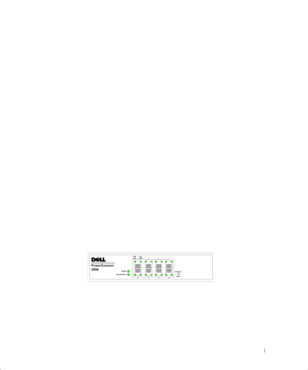
The following figure illustrates the PowerConnect 2808 front panel.
Figure 1-1. PowerConnect 2808 Front Panel
The PowerConnect 2808 supports the following ports:
• 8 Gigabit Ethernet copper ports
PowerConnect 2816
The following figure illustrates the PowerConnect 2816 front panel.
Dell PowerConnect 28xx Systems User Guide 9
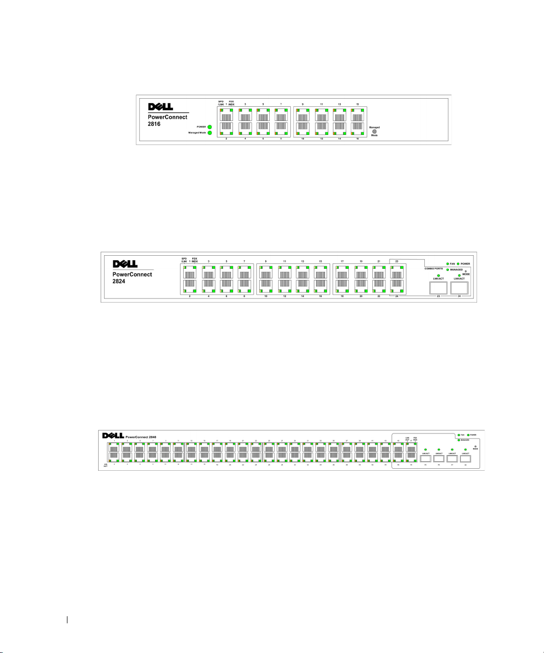
Figure 1-2. PowerConnect 2816 Front Panel
The PowerConnect 2816 supports the following ports:
• 16 Gigabit Ethernet copper ports
PowerConnect 2824
The following figure illustrates the PowerConnect 2824 front panel.
Figure 1-3. PowerConnect 2824 Front Panel
The PowerConnect 2824 supports the following ports:
• 24 Gigabit Ethernet copper ports
• 2 SFP combo ports (1000BASE-SX or 1000BASE-LX)
PowerConnect 2848
The following figure illustrates the PowerConnect 2848 front panel.
Figure 1-4. PowerConnect 2848 Front Panel
The PowerConnect 2848 supports the following ports:
• 48 Gigabit Ethernet copper ports
• 4 SFP combo ports (1000BASE-SX or 1000BASE-LX)
10 Dell PowerConnect 28xx Systems User Guide

Summary of PowerConnect Models
The following table summarizes the PowerConnect models.
Table 1-1. PowerConnect Models
Model Copper Ports/
RJ-45 Connectors
PowerConnect 2808 8 built-in 10/100/1000 Base-T ports none Internal console port none
PowerConnect 2816 16 built-in 10/100/1000 Base-T ports none External console port none
PowerConnect 2824 24 built-in 10/100/1000 Base-T ports 2 SFP (combo) External console port 1
PowerConnect 2848 48 built-in 10/100/1000 Base-T ports 4 SFP (combo) External console port 32
Optical Ports/
GbE
RS232 serial port baud rate is 9600 bps
Fans
Features
General Features
Management Modes
The device supports the following modes:
•
Managed Mode
•
Unmanaged Mode
configuration cannot be changed.
•
Secure Mode
configuration changes by removing the IP address of the device so that it becomes inaccessible for
configuration.
For more information about the management modes, see "Management Modes" on page 49.
— Provides switch management through the web interface.
— In this mode, the device operates as a hub with default configuration, and
— This mode keeps the existing configuration active, but it prevents users from making
Head of Line Blocking Prevention
Head of Line (HOL) blocking results in traffic delays and frame loss caused by traffic competing for the
same egress port resources. HOL blocking queues packets, and the packets at the head of the queue are
forwarded before packets at the end of the queue. By default, the device is configured so that the HOL
blocking prevention mechanism is active at all times, except when QoS (Quality of Service), Flow
Control or Back Pressure is active on a port where the HOL blocking prevention mechanism is disabled
on the whole system.
Back Pressure Support
On half-duplex links, the receiving port prevents buffer overflows by occupying the link so that it is
unavailable for additional incoming traffic. The user may enable or disable this feature on a
per-port basis. The default status on all ports is set to OFF.
Dell PowerConnect 28xx Systems User Guide 11

Auto Negotiation
Auto negotiation allows an Ethernet switch to advertise modes of operation. The auto negotiation
function provides the means to exchange information between two Ethernet switches that share a pointto-point link segment, and to automatically configure both Ethernet switches to take maximum
advantage of their transmission capabilities. Port advertisement allows the system administrator to
configure the port speeds advertised.
Jumbo Frames Support
Jumbo frames are frames with an MTU (Maximum Transmission Unit) size of up to 10K bytes. The
Jumbo Frames Support feature, utilizes the network optimally by transporting the same data using less
frames.
The main benefits of this facility are reduced transmission overhead and reduced host processing
overhead. Jumbo frames are used for server-to-server transfers.
AutoMDI/MDIX Support
The switch automatically detects whether the cable connected to an RJ-45 port is crossed or straight
through.
Standard wiring for end stations is Media-Dependent Interface (MDI) and the
s
tandard wiring for hubs
and switches is known as Media-Dependent Interface with Crossover (MDIX).
Auto MDI/MDIX works on 10/100/1000BASE-T Ethernet ports. This feature is automatically enabled for
the entire system and cannot be turned off by the user.
Flow Control Support (IEEE802.3X)
On Full Duplex links (FDX), the flow control mechanism allows the receiving side to signal to the
sending side that transmission must be halted temporarily, in order to prevent buffer overflows. Flow
control is enabled by default.
Virtual Cable Testing (VCT)
VCT technology provides the mechanism to detect and report potential cabling issues, such as cable
opens and cable shorts on copper links.
Cable analysis is available on Copper Cables (10BASE-T/100BASE-T/1000BASE-T), and is only done
when the link is down. When the system initiates a cable-testing operation, upon explicit user action, the
following parameters are detected:
• Cable Type and Status
•Cable Length
• Fault-Distance
12 Dell PowerConnect 28xx Systems User Guide

MAC Address Supported Features
MAC Address Capacity Support
The PowerConnect 2808, 2816, 2824 switches support a total of 8K MAC addresses, and the
PowerConnect 2848 supports a total of 16K MAC addresses.
Auto-Learning MAC Addresses
The switch enables MAC address auto-learning from incoming packets. The MAC addresses are stored in
the Bridging Table.
Automatic Aging for MAC Addresses
MAC addresses from which no traffic is received for a given period of time are aged out. This prevents
the Bridging Table from overflowing.
VLAN-aware MAC-based Switching in Managed and Secure Modes
In Managed or Secure mode, the switch system always performs VLAN-aware bridging. Classic bridging
(IEEE802.1D) is not performed (where frames are forwarded based only on their destination MAC
address). However, a similar functionality may be configured for untagged frames. Addresses are
associated with ports by learning them from the incoming frames source address.
802.1D Bridging in Unmanaged Mode
In Unmanaged Mode, the switch performs classic bridging. Frames are forwarded based on their
destination MAC address only, regardless of the VLAN tag.
MAC Multicast Support
Multicast service is a limited broadcast service, which allows one-to-many and many-to-many
connections for information distribution. Layer 2 Multicast service is where a single frame is addressed to
a specific Multicast address, from where copies of the frame are transmitted to the relevant ports. IGMP
Snooping is supported, including IGMP Querier which simulates the behavior of a multicast router,
allowing snooping of the layer 2 multicast domain even though there is no multicast router. When
Multicast groups are statically enabled, you can set the destination port of registered groups, as well as
define the behavior of unregistered multicast frames.
Layer 2 Features
Green Ethernet
Green Ethernet, also known as Energy Efficient Ethernet, is an effort to make networking equipment
environmentally friendly, specifically by reducing power usage of Ethernet connections. The following
methods are supported by the device:
•
Energy-Detect
— Auto-detection of inactivity on a port, and subsequent reducing of transmit power.
Dell PowerConnect 28xx Systems User Guide 13

•
Short-Reach
IGMP Snooping
— Reduction of power over Ethernet cables shorter than 40m.
Internet Group Membership Protocol (IGMP) Snooping examines IGMP frame contents, when they are
forwarded by the device from work stations to an upstream Multicast router. From the frame, the device
identifies work stations configured for Multicast sessions, and which Multicast routers are sending
Multicast frames.
Port Mirroring
The port mirroring mechanism monitors and mirrors network traffic by forwarding copies of incoming
and outgoing packets from a monitored port to a monitoring port. Users can specify which target port
receives copies of all traffic passing through one or more source ports.
Storm Control
Storm Control enables limiting the amount of Multicast, Broadcast and Unknown Unicast frames
accepted and forwarded by the switch. When Layer 2 frames are forwarded, Broadcast and Multicast
frames are flooded to all ports on the relevant VLAN. All nodes connected to these ports accept and
attempt to process these frames, thus placing load on both the network links and the host operating
system.
Dynamic VLAN Assignment (DVA)
Dynamic VLAN Assignment allows automatic assignment of users to VLANs during the RADIUS server
authentication. When a user is authenticated by the RADIUS server, the user is automatically joined to
the VLAN configured on the RADIUS server.
VLAN Supported Features
VLAN Support
VLANs are collections of switching ports that comprise a single broadcast domain. Packets are classified
as belonging to a VLAN based on either the VLAN tag or based on a combination of the ingress port and
package contents. Packets sharing common attributes can be grouped in the same VLAN.
Port Based Virtual LANs (VLANs)
Port-based VLANs classify incoming packets to VLANs based on their ingress port.
Link Aggregation
The PowerConnect 28xx switches support up to eight aggregated links. Each of the eight aggregated
links may be defined with up to eight member ports to form a single Link Aggregated Group (LAG).
The benefits of this facility are:
• Fault tolerance protection from physical link disruption
14 Dell PowerConnect 28xx Systems User Guide

• Higher bandwidth connections
• Improved bandwidth granularity
• High bandwidth server connectivity
A LAG is composed of ports with the same speed set to full-duplex operation.
DHCP Server
Dynamic Host Configuration Protocol is a method of managing network parameter assignment from a
single DHCP server. The Dynamic Host Configuration Protocol (DHCP) automates the assignment of
IP addresses, subnet masks, default gateway, and other IP parameters.
BootP and DHCP Clients
DHCP (Dynamic Host Configuration Protocol) enables additional setup parameters to be received from
a network server upon system startup. DHCP service is an on-going process. DHCP is an extension to
BootP.
The BootP client is operational if there is a corrupted or invalid software image. The BootP client then
continuously attempts to find a BootP server, by sending BootP requests to all ports on the default
VLAN, until a BootP server replies. The information replied is then used to provide the switch system
with a TFTP server IP address and a download file name. The switch can then configure these values to
the TFTP client and try to download a valid runtime image.
Spanning Tree Protocol Features
Spanning Tree Protocol (STP)
802.1d Spanning tree is a standard Layer 2 switch requirement that allows bridges to automatically
prevent and resolve L2 forwarding loops. Switches exchange configuration messages using specifically
formatted frames and selectively enable and disable forwarding on ports.
Fast Link
STP can take up to 30-60 seconds to converge. During this time, STP detects possible loops, allowing
time for status changes to propagate and for relevant devices to respond. 30-60 seconds is considered too
long of a response time for many applications. The Fast Link option bypasses this delay, and can be used
in network topologies where forwarding loops do not occur.
IEEE 802.1w Rapid Spanning Tree
Spanning Tree can take 30-60 seconds for each host to decide whether its ports are actively forwarding
traffic. Rapid Spanning Tree (RSTP) detects uses of network topologies to enable faster convergence,
without creating forwarding loops.
STP Root Guard
Root guard restricts the interface from functioning as the root port for the switch
Dell PowerConnect 28xx Systems User Guide 15

Class of Service (CoS) Features
The PowerConnect 28xx system enables users to define various services for traffic classes of service. The
underlying mechanism for supporting bandwidth management and control is based on the use of
multiple priority queues for classifying traffic. The switches support four queues per port.
A CoS is defined by the user, whereby packets are related to the same Class of Service. After a packet has
been classified, it is assigned to one of the queues. The PowerConnect 28xx system can classify according
to IPv4 information (DSCP).
Class of Service 802.1p Support
The IEEE 802.1p signaling technique is an OSI Layer 2 standard for marking and prioritizing network
traffic at the data link/MAC sub-layer. 802.1p traffic is classified and sent to the destination. No
bandwidth reservations or limits are established or enforced. 802.1p is a spin-off of the 802.1Q (VLANs)
standard.
Ethernet Switch Management Features
Web-Based Management
With a Web-based management interface, the Ethernet Switches’ system can be managed from any
Web browser. The system contains an Embedded Web Server (EWS), which serves HTML pages,
through which the system can be monitored and configured.
TFTP Trivial File Transfer Protocol
The PowerConnect 28xx switches support software boot image and software download through TFTP.
Remote Monitoring
Remote Monitoring (RMON) is an extension to the Simple Network Management Protocol (SNMP),
which provides network traffic statistics. RMON defines current and historical MAC-layer statistics and
control objects, allowing real-time information to be captured across the entire network. The switches
support one RMON group for Ethernet statistics. The system provides a means to collect the statistics
defined in RMON and to view the results, using the Web management interface in the system.
16 Dell PowerConnect 28xx Systems User Guide
Hardware Description
Switch Port Configurations
PowerConnect 28xx Front and Back Panel Port Description
The Dell™ PowerConnect™ 28xx switches use 10/100/1000BASE-T ports on the front panel for
connecting to a network.
The Gigabit Ethernet ports can operate at 10, 100 or 1000 Mbps. These ports support autonegotiation, duplex mode (Half or Full duplex), and flow control. The combo 1000 Mbps optical
ports can only operate at 1000 Mbps, full-duplex mode.
The following figures illustrate the front panels and back panels of the PowerConnect 28xx switches.
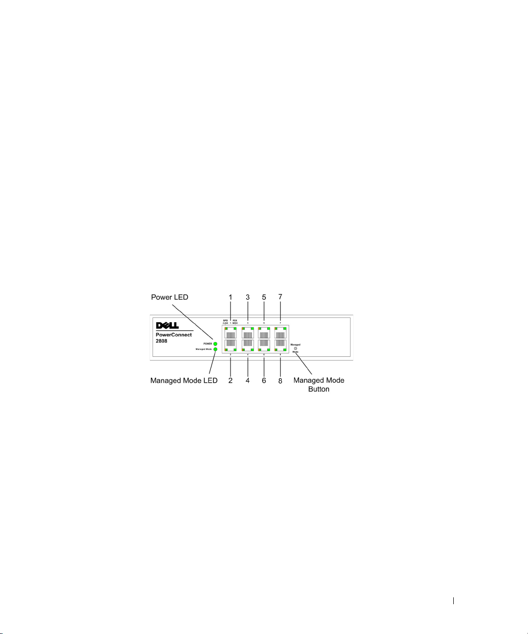
Figure 2-1. PowerConnect 2808 Front Panel
2
On the front panel there are eight ports which are numbered 1 to 8, top down and left to right. On
each port there are LEDs (Light Emitting Diode) to indicate the port status.
On the left side of the front panel is the Managed Mode LED which indicates the Ethernet switch
operational status and the management mode. The Power LED on the front panel indicates whether
the device is powered on or not. A Mode push-button, located on the right side on the front panel is
used to transition between management modes and to reset the device. For more information about
management modes and transitioning between them, see "Management Modes" on page 49.
Dell PowerConnect 28xx Systems User Guide 17
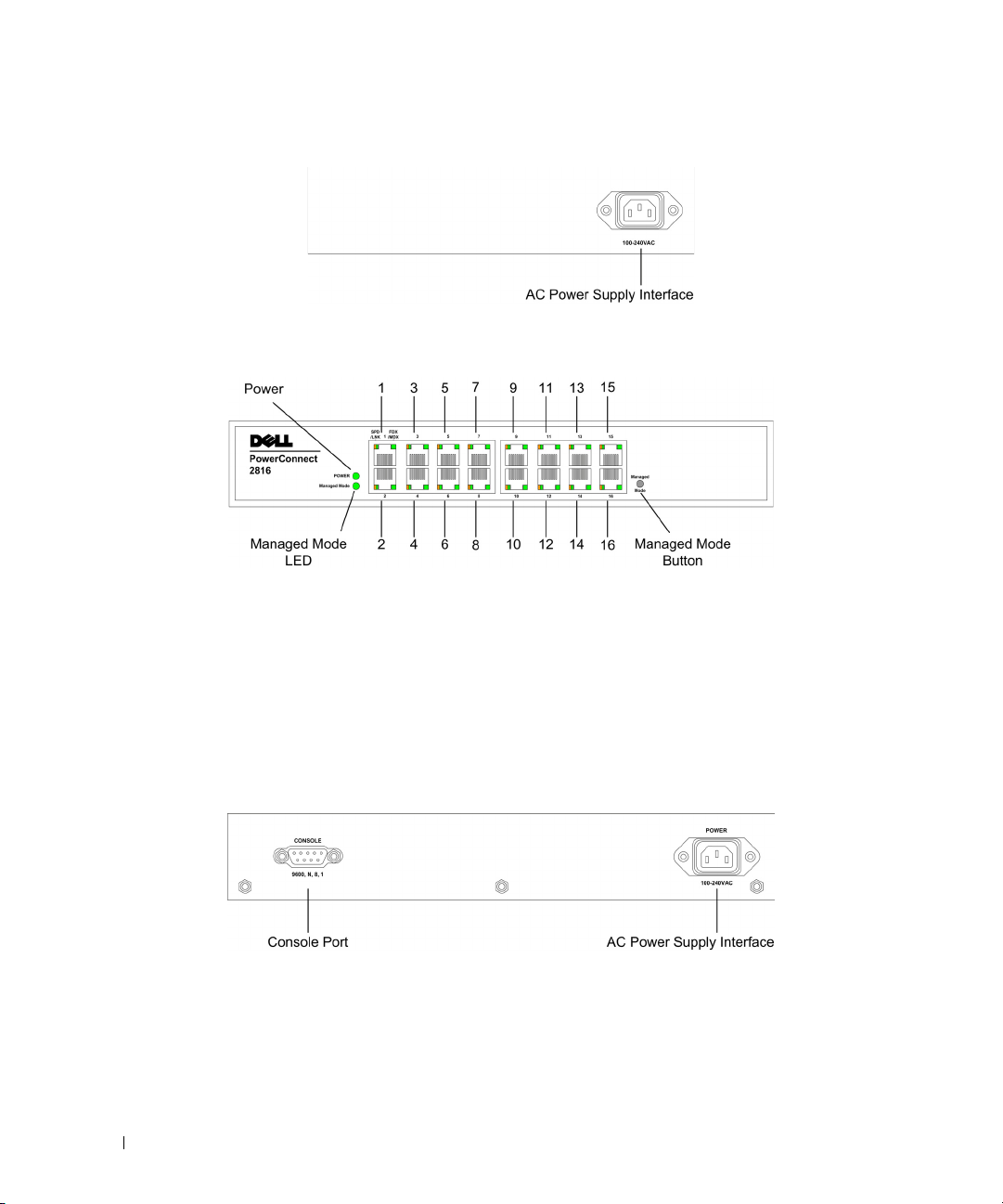
Figure 2-2. PowerConnect 2808 Back Panel
Figure 2-3. PowerConnect 2816 Front Panel
On the front panel there are 16 ports which are numbered 1 to 16, top down and left to right. On each
port there are LEDs to indicate the port status.
On the left side of the front panel is the Managed Mode LED which indicates the Ethernet switch
operational status and the management mode. The Power LED on the front panel indicates whether the
device is powered on or not. A Mode push-button, located on the right side on the front panel, is used to
transition between management modes and to reset the device. For more information about
management modes and transitioning between them, see "Management Modes" on page 49.
Figure 2-4. PowerConnect 2816 Back Panel
18 Dell PowerConnect 28xx Systems User Guide
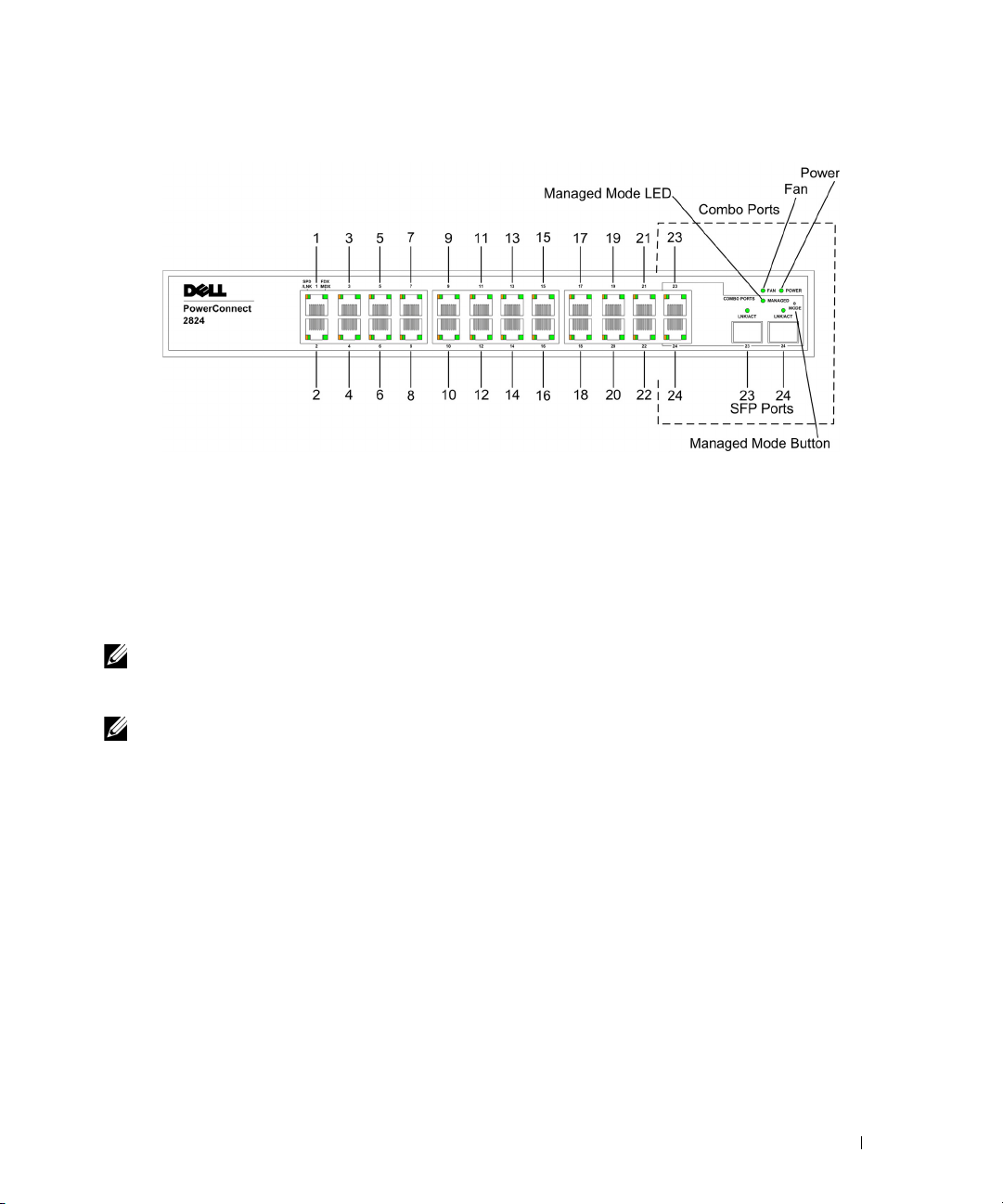
Figure 2-5. PowerConnect 2824 Front Panel
On the front panel there are 24 ports which are numbered 1 to 24, top down and left to right. On each
port there are LEDs to indicate the port status. There are two SFP (Small Form-Factor Plugable) ports,
designated as ports 23 and 24, for fiber connection. The two combo ports are logical ports with two
physical connections:
• An RJ-45 connection for Twisted Pair (TP) copper cabling
• An SFP port for swappable optical transceiver, which offers high-speed 1000BASE-SX or 1000BASELX connection.
NOTE: Only one of the two physical connections of a combo port can be used at any one time. Port features and
port controls are determined by the physical connection used. The system automatically detects the media used on
a combo port, and utilizes the information in all the control interfaces.
NOTE: The system can switch from the RJ-45 to the SFP (or vice versa) without resetting the device. If both RJ-45
and SFP ports are present, the SFP port will be the active port, whereas the RJ-45 port will be disabled.
On the front panel is the Managed Mode LED which indicates the Ethernet switch operational status
and the management mode. The Fan LED indicates the device fan operations status, and the Power
LED on the front panel indicates whether the device is powered on or not. A Mode push-button, located
on the right side on the front panel is used to transition between management modes and to reset the
device. For more information about management modes and transitioning between them, see
"Management Modes" on page 49.
Dell PowerConnect 28xx Systems User Guide 19
Figure 2-6. PowerConnect 2824 Back Panel
Figure 2-7. PowerConnect 2848 Front Panel
On the front panel there are 48 ports, which are numbered 1 to 48, top down and left to right. On each
port, there are LEDs to indicate the port status. There are four SFP (Small Form-Factor Plugable) ports,
designated as ports 45, 46, 47 and 48, for fiber connection. The four combo ports are logical ports with
two physical connections:
• An RJ-45 connection for Twisted Pair (TP) copper cabling.
• An SFP port for swappable optical transceiver, which offers high-speed 1000BASE-SX or
1000BASE-LX connection.
NOTE: Only one of the two physical connections of a combo port can be used at any one time. Port features and
port controls are determined by the physical connection used. The system automatically detects the media used on
a combo port, and utilizes the information in all the control interfaces.
NOTE: The system can switch from the RJ-45 to the SFP (or vice versa) without resetting the device. If both RJ-45
and SFP ports are present, the SFP port will be the active port, whereas the RJ-45 port will be disabled.
On the top right side of the front panel is the Managed Mode LED which indicates the Ethernet switch
operational status and the management mode. The Fan LED indicates the device fan operations status,
and the Power LED on the front panel indicates whether the device is powered on or not. A Mode push-
20 Dell PowerConnect 28xx Systems User Guide
button, located on the right side on the front panel is used to transition between management modes
and to reset the device. For more information about management modes and transitioning between
them, see "Management Modes" on page 49.
Fans are provided on the side panel. The back panel contains an AC Power Supply Interface.
The following figure illustrates the back panel of the PowerConnect 2848 device.
Figure 2-8. PowerConnect 2848 Back Panel
Physical Dimensions
The PowerConnect 2808 switch has the following physical dimensions:
• Height — 43.2 mm (1.7008 in.)
• Width — 256 mm (10.079 in.)
• Depth — 161.7 mm (6.366 in.)
The PowerConnect 2816 and PowerConnect 2824 switches have the following physical dimensions:
• Height — 43.2 mm (1.7008 in.)
• Width — 330 mm (12.992 in.)
• Depth — 230.50 mm (9.075 in.)
The PowerConnect 2848 switch has the following physical dimensions:
• Height — 43.2 mm (1.70 in.)
• Width — 440 mm (17.32 in)
• Depth — 255 mm (10.04 in.)
LED Definitions
The front panel contains LEDs that indicate the status of links, power supply, fan status, and Managed
Mode status.
Dell PowerConnect 28xx Systems User Guide 21

Power LED
On the PowerConnect 28xx front panel there is a Power LED. The following table describes the Power
Supply status LED indications.
Table 2-1. Power LED Indications
LED Color Description
Green Solid The switch is turned on.
Off The switch is not turned on.
Managed Mode LED
On the PowerConnect 28xx front panel there is a Managed Mode LED monitoring the switch node as
well as indicating diagnostic test results. The following table describes the Managed Mode LED
indications. For more information about management modes and transitioning between them, see
"Management Modes" on page 49.
Table 2-2. Managed Mode LED Indications
LED Color Description
Green Flashing Indicates diagnostics in progress, firmware loading, or Management Mode transition.
Green Solid Indicates the switch is in Managed Mode.
Amber Solid Diagnostics has failed.
Amber Flashing No valid image.
Off Indicates Unmanaged mode or Secure mode.
Fan LED (2824/2848 only)
On the PowerConnect 2824 and PowerConnect 2848 front panel there is a fan LED. The following table
describes the fan status LED indications.
Table 2-3. Fan LED Indications
LED Color Description
Green Solid All fans are operating correctly.
Red Solid One or more fans have failed.
Port LEDs
10/100/1000BASE-T Port LEDs
Each 10/100/1000BASE-T port has two LEDs. Speed/Link/Activity is indicated on the left LED and the
duplex mode is indicated on the right LED.
The following figure illustrates the RJ-45 10/100/1000BASE-T LEDs.
22 Dell PowerConnect 28xx Systems User Guide
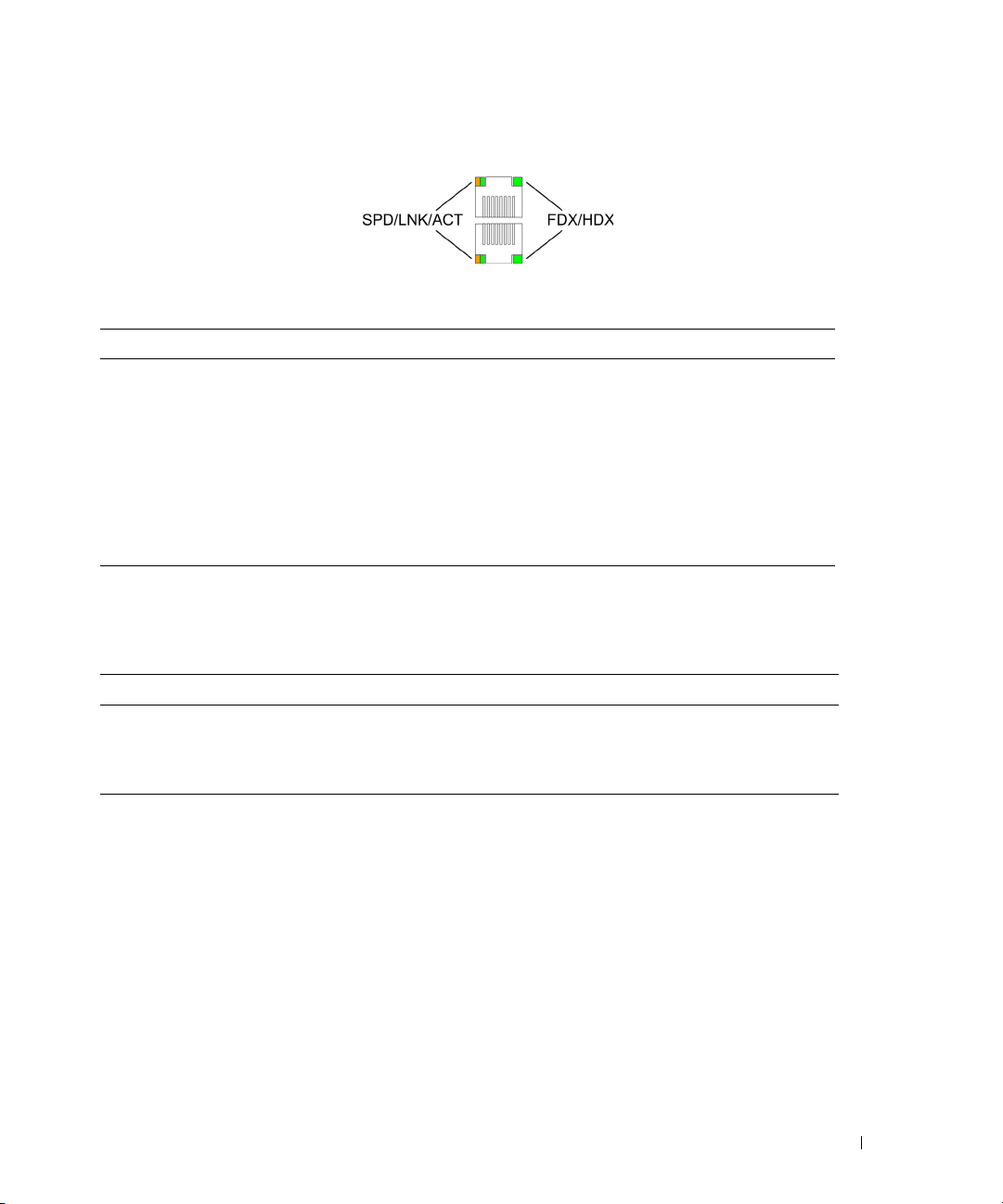
Figure 2-9. RJ-45 Copper-based 10/100/1000BASE-T LEDs
The RJ-45 LED indications are described in the following table:
Table 2-4. RJ-45 Copper based 10/100/ 1000BASE-T LED Indications
LED Color Description
Left LED Green Solid The port is linked at 1000 Mbps.
Green Flashing The port is transmitting or receiving data at 1000 Mbps.
Amber Solid The port is linked at either 10 or 100 Mbps.
Amber Flashing The port is transmitting or receiving data at 10 or 100 Mbps.
Off No link is established.
Right LED Green Solid The port is currently transmitting in Full Duplex mode.
Off The port is operating in Half Duplex mode.
SFP Port LED
The following table describes the SFP LED indications.
Table 2-5. SFP LED Indications
LED Color Description
Green Solid Link is established.
Green Flashing Activity is occurring.
Off No link is established.
Managed Mode Button
The PowerConnect 28xx has a Mode push button on the front panel. The Mode button is for changing
between Managed Mode and Unmanaged (or Secure) Mode and for resetting the device. To transition
between modes, press the button normally. To reset the device, press and hold the button for at least 7
seconds. For more information about management modes and transitioning between them, see
"Management Modes" on page 49.
Switch Ventilation Fan
The PowerConnect 2848 switch has three fans and the PowerConnect 2824 switch has one fan for system
ventilation. The PowerConnect 2808 and PowerConnect 2816 devices have no internal fans.
Dell PowerConnect 28xx Systems User Guide 23
Cables, Port Connections, and Pinout Information
This section explains the switch physical interfaces, and provides information about cables and port
connections. Copper cable diagnostics are supported. High-speed workstations, hubs, routers, or other
switches are connected through standard RJ-45 connectors to the switch physical interface ports, located
on the front panel. For each device, the supported mode is set to Half Duplex, Full Duplex, and Auto.
1000BASE-T Cable Requirements
All Category 5 UTP cables that are used for 100BASE-TX connections also operate with 1000BASE-T,
provided if all four wire pairs are connected. However, it is recommended that enhanced Category 5
(Category 5e)cable is used for all critical connections or any new cable installations. The Category 5e
specification includes test parameters that are only recommendations for Category 5, and comply with
the IEEE 802.3ab standards.
RJ-45 Connections for 10/100/1000BASE-T Ports
The 10/100/1000BASE-T ports are copper Twisted-Pair ports.
Table 2-6. Port Default Settings
Connector Port/Interface Cable
RJ-45 10/100/1000BASE-T Port Cat.5
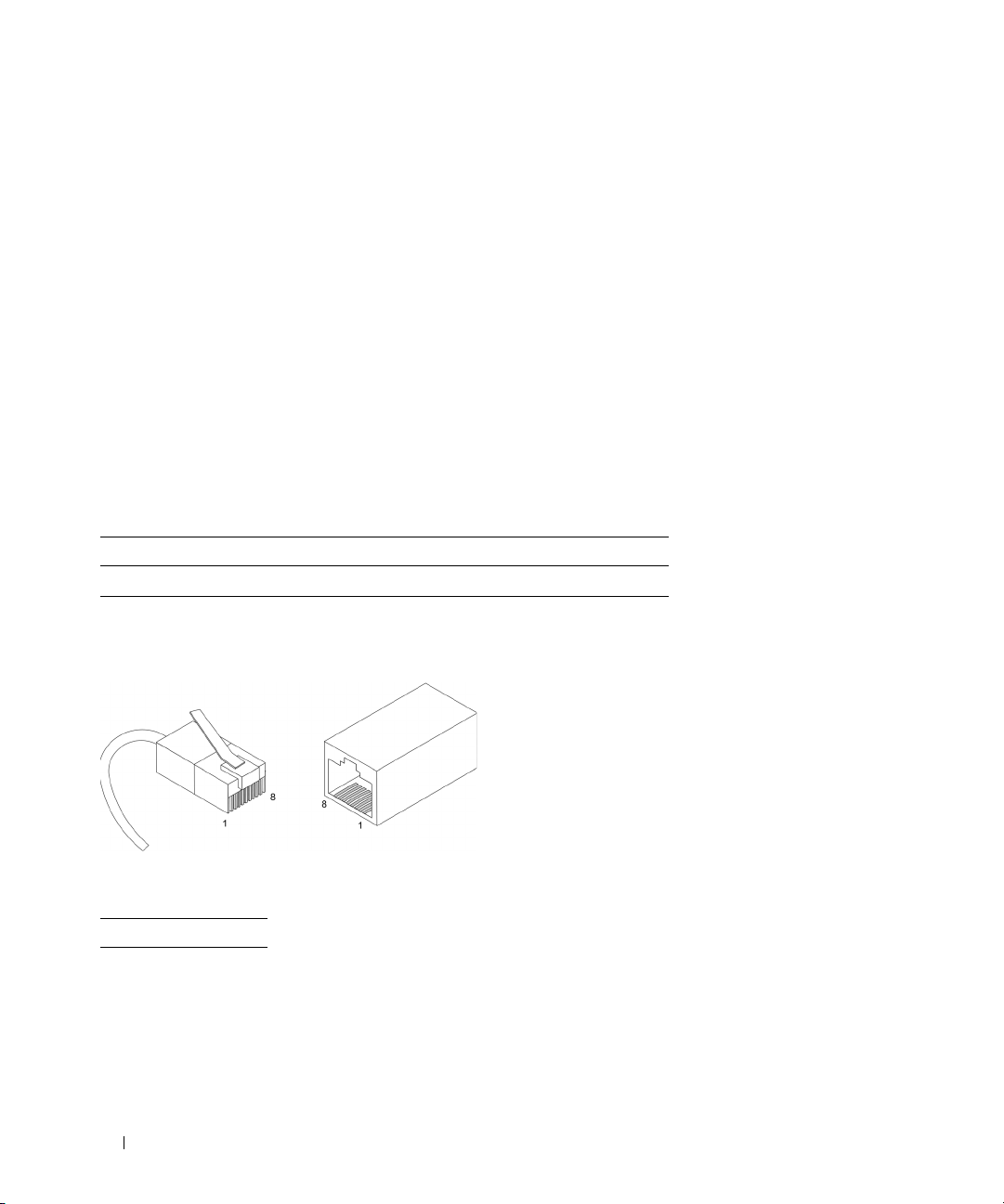
The following figure illustrates the RJ-45 pin connector pin numbers.
Figure 2-10. RJ-45 Pin Numbers
The RJ-45 pin number allocation for the 10/100/1000BASE-T ports is listed in the following table.
Table 2-7. RJ-45 Pin Number Allocation for 10/100/ 1000BASE-T Ethernet Port
Pin No Function
1 TxRx 1+
2 TxRx 1-
3 TxRx 2+
4 TxRx 2-
5 TxRx 3+
24 Dell PowerConnect 28xx Systems User Guide

Table 2-7. RJ-45 Pin Number Allocation for 10/100/ 1000BASE-T Ethernet Port
Pin No Function
6 TxRx 3-
7 TxRx 4+
8 TxRx 4-
SFP Ports
The PowerConnect 2824 switch supports two SFP transceivers combo ports, and the PowerConnect 2848
switch supports four SFP transceivers combo ports for various fiber-based modules (1000BASE-SX or
1000BASE-LX). Only one of the two physical connections of a combo port can be used at any time. The
system can switch from the RJ-45 to the SFP (or vice versa) without a system reset. The system
automatically detects the media used on a combo port, and utilizes this information in the control
interfaces.
PowerConnect 2824 switch supports SFP diagnostics. The optical transceiver provides access to a set of
parameters that can be monitored and displayed to the system administrator.
NOTE: If both RJ-45 and SFP ports are present, the SFP port will be the active port, whereas the RJ-45 port will be
disabled and ignored.
The pin number allocation for the SFP ports is listed in the following table.
Table 2-8. SFP Pin Connections
Pin No Use
1 Transmitter ground (common with receiver ground)
2 Transmitter fault
3 Transmitter disable; laser output disabled on high or open.
4 Module definition 2; data line for serial ID.
5 Module definition 1; clock line for serial ID.
6 Module definition 0; grounded within the module.
7 Rate select; no connection required.
8 Loss of signal indication; logic 0 indicates normal operation.
9 Receiver ground (common with transmitter ground)
10 Receiver ground (common with transmitter ground)
11 Receiver ground (common with transmitter ground)
12 Receiver inverted data out; AC coupled.
13 Receiver non-inverted data out; AC coupled.
14 Receiver ground (common with transmitter ground)
Dell PowerConnect 28xx Systems User Guide 25

Table 2-8. SFP Pin Connections
Pin No Use
15 Receiver power supply
16 Transmitter power supply
17 Transmitter ground (common with receiver ground)
18 Transmitter non-inverted data in
19 Transmitter inverted data in
20 Transmitter ground (common with receiver ground)
Power Connectors
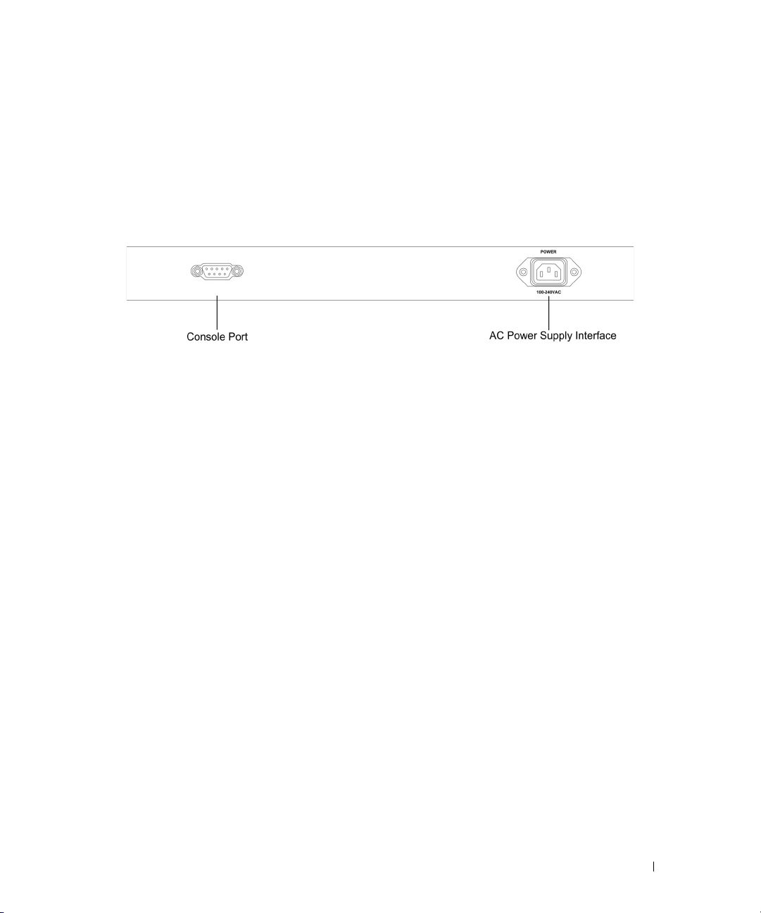
The PowerConnect 28xx is powered by using the AC internal power supply.
Internal Power Supply Connector
The PowerConnect 28xx supports a single internal power supply to provide power for switching
operations. The internal power supply supports input voltages between 100 and 240 VAC. The AC power
connector is located on the back panel of the switch.
26 Dell PowerConnect 28xx Systems User Guide

Installing the PowerConnect Device
This section contains information about device unpacking, location, installation, and cable
connections.
Installation Precautions
CAUTION Before performing any of the following procedures, read and follow the safety instructions located
in the
System Information Guide
CAUTION Observe the following points before performing the procedures in this section:
• Ensure that the rack or cabinet housing the device is adequately secured to prevent it from
becoming unstable and/or falling over.
• Ensure that the power source circuits are properly grounded.
• Observe and follow the service markings. Do not service any device except as explained in the
system documentation. Opening or removing covers marked with a triangular symbol with a
lighting bolt may cause electrical shock. These components are to be serviced by trained service
technicians only.
• Ensure that the power cable, extension cable, and/or plug is not damaged.
• Ensure that the device is not exposed to water.
• Ensure that the device is not exposed to radiators and/or heat sources.
• Ensure that the cooling vents are not blocked.
• Do not push foreign objects into the device, as it may cause a fire or electric shock.
• Use the device only with approved equipment.
• Allow the device to cool before removing covers or touching internal equipment.
• Ensure that the device does not overload the power circuits, wiring, and over-current protection.
To determine the possibility of overloading the supply circuits, add together the ampere ratings of
all switches installed on the same circuit as the device. Compare this total with the rating limit for
the circuit.
• Do not install the device in an environment where the operating ambient temperature might
exceed 45ºC (113ºF).
• Ensure that the airflow around the front, sides, and back of the device is not restricted.
included in the Dell Documentation.
3
Dell PowerConnect 28xx Systems User Guide 27

Site Requirements
The PowerConnect 28xx can be mounted in a standard equipment rack, placed on a tabletop, or
mounted on the wall.
Before installing the device, verify that the site selected for the device meets the following site
requirements:
•
Power
— The device is installed within 1.5 m (5 feet) of a grounded, easily accessible outlet 220/110
VAC, 50/60 Hz. If the device has two power supplies, the site should have two power outlets with
different power feeders.
•
General
•
Clearance
power connections, and ventilation.
•
Cabling
amplifiers, power lines, and fluorescent lighting fixtures.
•
Ambient Requirements
113 °F) at a relative humidity of up to 95%, non-condensing. Verify that water or moisture cannot enter
the device case.
— Ensure that the power supply is correctly installed.
— There is adequate frontal clearance for operator access. Allow clearance for cabling,
— Cabling is routed to avoid sources of electrical noise such as radio transmitters, broadcast
— The ambient device operating temperature range is 0 to 45 °C (32 to
Unpacking
Package Contents
While unpacking the device, ensure that the following items are included:
•The device
• AC power cable
• Self-adhesive rubber pads (for on-shelf installation)
• Rack-mount kit for installation
• Documentation CD
• Product Information Guide
Unpacking the Device
To unpack the PowerConnect device:
NOTE: Before unpacking the device, inspect the packaging and report any evidence of damage.
1
Place the box on a clean flat surface.
2
Open the box or remove the box top.
3
Carefully remove the device from the package and place it on a secure, stable and clean surface.
4
Remove all packing material.
28 Dell PowerConnect 28xx Systems User Guide

5
Inspect the product for damage. Report any damage immediately.
Mounting the Device
Overview
There are three device mounting options:
• Installing in a Rack
• Installing on a Flat Surface
• Installing on a Wall
Device Rack Installation
CAUTION Read the safety information in the Product Information Guide as well as the safety information for other
devices that connect to or support the switch.
CAUTION Disconnect all cables from the device before mounting the device in a rack or cabinet.
CAUTION When mounting multiple devices into a rack, mount the devices from the bottom up.
Install the device in a rack as follows:
1
Place the supplied rack-mounting bracket on one side of the device ensuring the mounting holes on
the device line up to the mounting holes on the rack mounting bracket. The following figure illustrates
where to mount the brackets.
Dell PowerConnect 28xx Systems User Guide 29
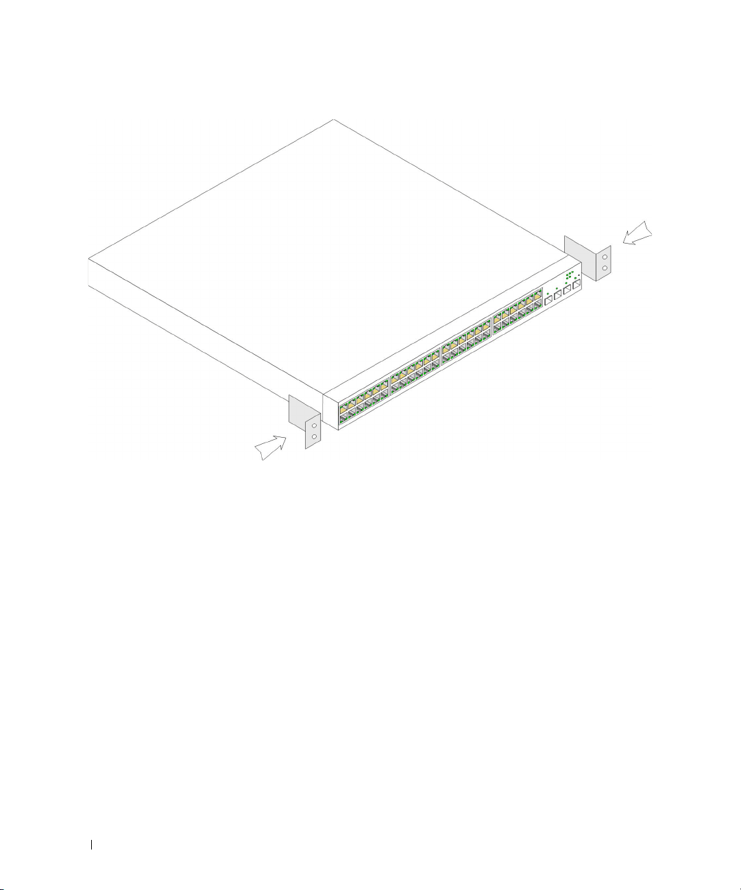
Figure 3-1. Bracket Installation for Rack Mounting
2
Insert the supplied screws into the rack mounting holes and tighten with a screwdriver.
3
Repeat the process for the rack-mounting bracket on the other side of the device.
4
Insert the device into the rack, ensuring the rack-mounting holes on the device line up to the
mounting hole on the rack.
5
Secure the device to the rack with the rack screws (not provided). Fasten the lower pair of screws before
the upper pair of screws. Ensure that the ventilation holes are not obstructed.
Installing on a Flat Surface
The device must be installed on a flat surface if it is not installed on a rack. The surface must be able to
support the weight of the device and the device cables.
1
Attach the self-adhesive rubber pads (provided with the device) on each marked location on the
bottom of the chassis.
2
Set the device on a flat surface, while leaving 2 inches (5.08 cm) on each side and 5 inches (12.7 cm) at
the back.
3
Ensure that the device has proper ventilation.
30 Dell PowerConnect 28xx Systems User Guide
 Loading...