

Dell Latitude C600 Service Manual

Dell Latitude C600/C500 Series Service Manual
Dell™ Latitude™ C600/C500 Series
Service Manual
Before You Begin
Preparing to Work Inside the Computer
Recommended Tools
Screw Identification
Removing and Replacing Parts
Components
Hard Drive
Memory Module
Mini-PCI Card Assembly
Keyboard Assembly
Removing the Display Assembly
Display Assembly Latch
Hinge Covers
Palmrest Assembly
Microprocessor Thermal Cooling Assembly
Hybrid Cooling Fan
Microprocessor Module
Reserve Battery
Speaker Assemblies
System Board Assembly
Battery and Modular Bay Latch Assemblies
Notes, Notices, and Cautions
NOTE: A NOTE indicates important information that helps you make better use
of your computer.
NOTICE: A NOTICE indicates either potential damage to hardware or loss of
data and tells you how to avoid the problem.
file:///F|/Service%20Manuals/Dell/Latitude/c500-600/index.htm (1 of 2) [2/28/2004 7:53:17 AM]

Before You Begin : Dell Latitude C600/C500 Series Service Manual
Back to Contents Page
Before You Begin
Dell™ Latitude™ C600/C500 Series Service Manual
Preparing to Work Inside the Computer
Recommended Tools
Screw Identification
Preparing to Work Inside the Computer
NOTICE: Only a certified service technician should perform repairs on your
system. Damage due to servicing that is not authorized by Dell is not covered
by your warranty.
NOTICE: To avoid damaging the computer, perform the following steps before
you begin working inside the computer.
1. Make sure that the work surface is clean to prevent scratching the computer
cover.
2. Save any work in progress and close all open application programs.
3. Turn off the computer and all attached devices.
NOTE: Make sure the computer is turned off and not in suspend-to-disk or
hibernate mode. If you cannot shut down the computer using the computer's
operating system, press and hold the power button for 4 seconds.
4. Make sure the computer is undocked.
5. Disconnect the computer from the electrical outlet.
6. To avoid possible damage to the system board, wait 10 to 20 seconds and then
disconnect any attached devices.
file:///F|/Service%20Manuals/Dell/Latitude/c500-600/begin.htm (1 of 6) [2/28/2004 7:53:27 AM]

Before You Begin : Dell Latitude C600/C500 Series Service Manual
7. Disconnect all other external cables from the computer.
8. Remove any installed PC Cards or plastic blanks from the PC Card slot.
9. Close the display and turn the computer upside down on a flat work surface.
NOTICE: To avoid damaging the system board, you must remove the main
battery and secondary battery (if present) before you service the computer.
10. Remove the primary battery from the battery bay and the secondary battery
from the modular bay, if a secondary battery is in use.
11. Remove any installed device in the modular bay.
12. To dissipate any static electricity while you work, use a wrist grounding strap or
periodically touch an unpainted metal surface.
13. Handle components and cards with care. Do not touch the components or
contacts on a card. Hold a card by it edges or by its metal mounting bracket.
Hold a component such as a microprocessor by its edges, not by its pins.
Recommended Tools
The procedures in this manual require the following tools:
● #1 magnetized Phillips screwdriver
● Small flat-blade screwdriver
● Small plastic scribe
● Microprocessor extractor
● Flash BIOS update program diskette or CD (required only when upgrading the
microprocessor or replacing the reserve battery)
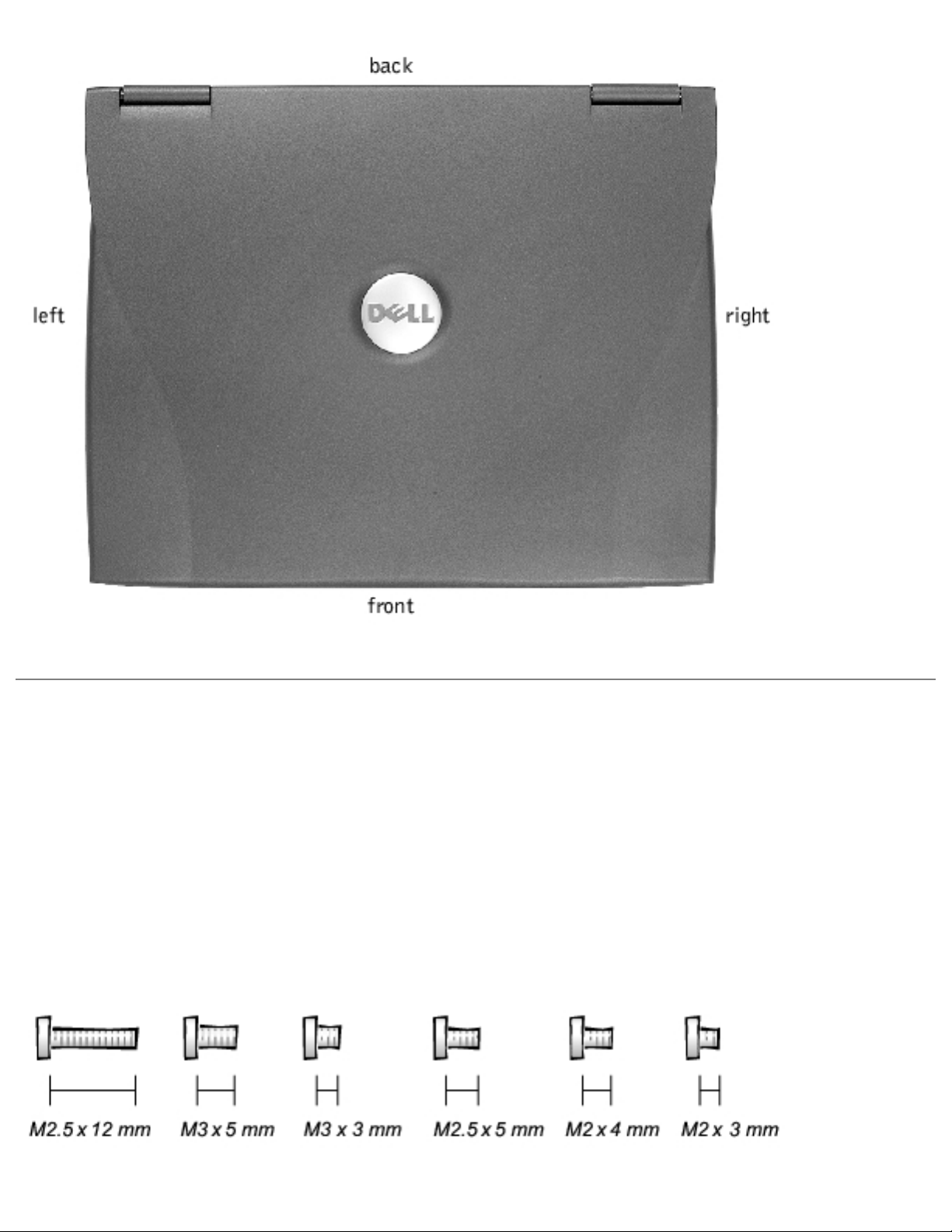
System Orientation
file:///F|/Service%20Manuals/Dell/Latitude/c500-600/begin.htm (2 of 6) [2/28/2004 7:53:27 AM]
Before You Begin : Dell Latitude C600/C500 Series Service Manual
Screw Identification
When you are removing and replacing components, photocopy the placemat as a tool
to lay out and keep track of the component screws. The placemat provides the
number of screws and the sizes.
Screw Identification
file:///F|/Service%20Manuals/Dell/Latitude/c500-600/begin.htm (3 of 6) [2/28/2004 7:53:27 AM]
Before You Begin : Dell Latitude C600/C500 Series Service Manual
NOTICE: When reinstalling a screw, you must use a screw of the correct
diameter and length. Make sure that the screw is properly aligned with its
corresponding hole, and avoid overtightening.
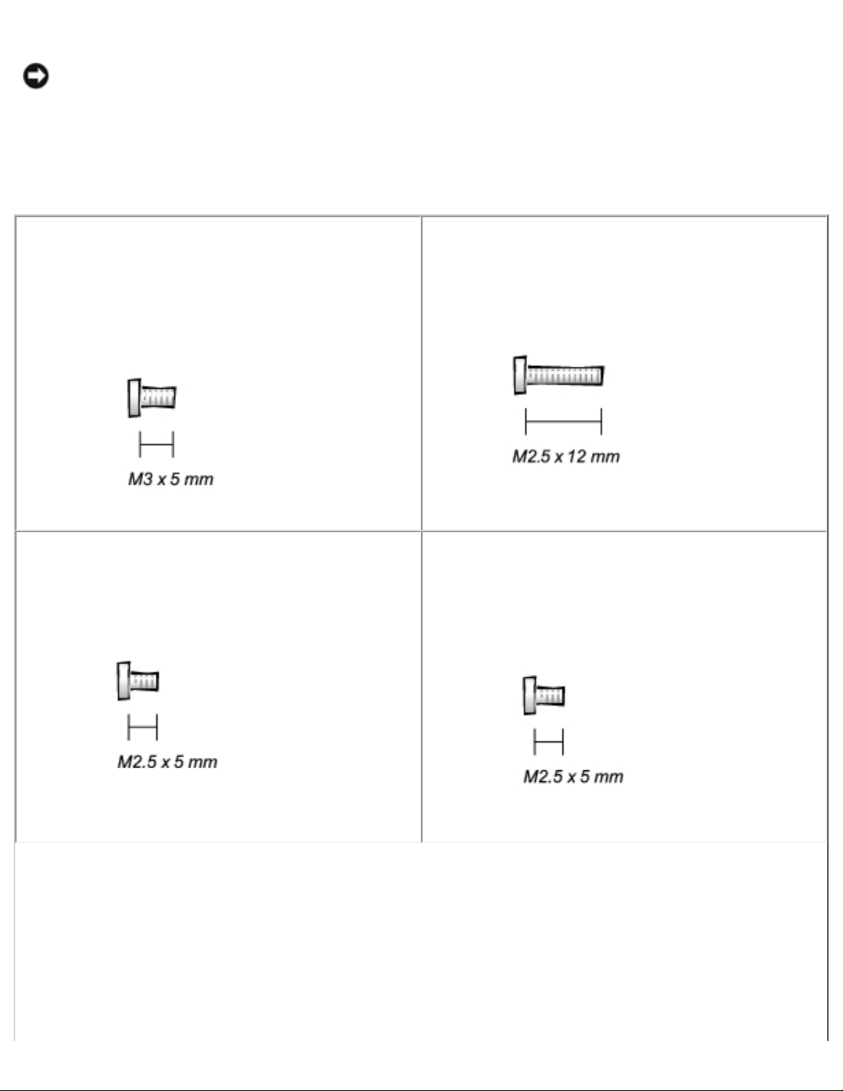
Screw Placement
Hard Drive
Door Security:
(1 each)
Keyboard to Bottom Case Assembly:
(5 each)
Display Assembly Bezel:
(6 each)
Rubber Screw Covers (6 each)
Display Assembly Hinge Bracket to
Bottom Case Assembly:
(5 each)
file:///F|/Service%20Manuals/Dell/Latitude/c500-600/begin.htm (4 of 6) [2/28/2004 7:53:27 AM]
Before You Begin : Dell Latitude C600/C500 Series Service Manual
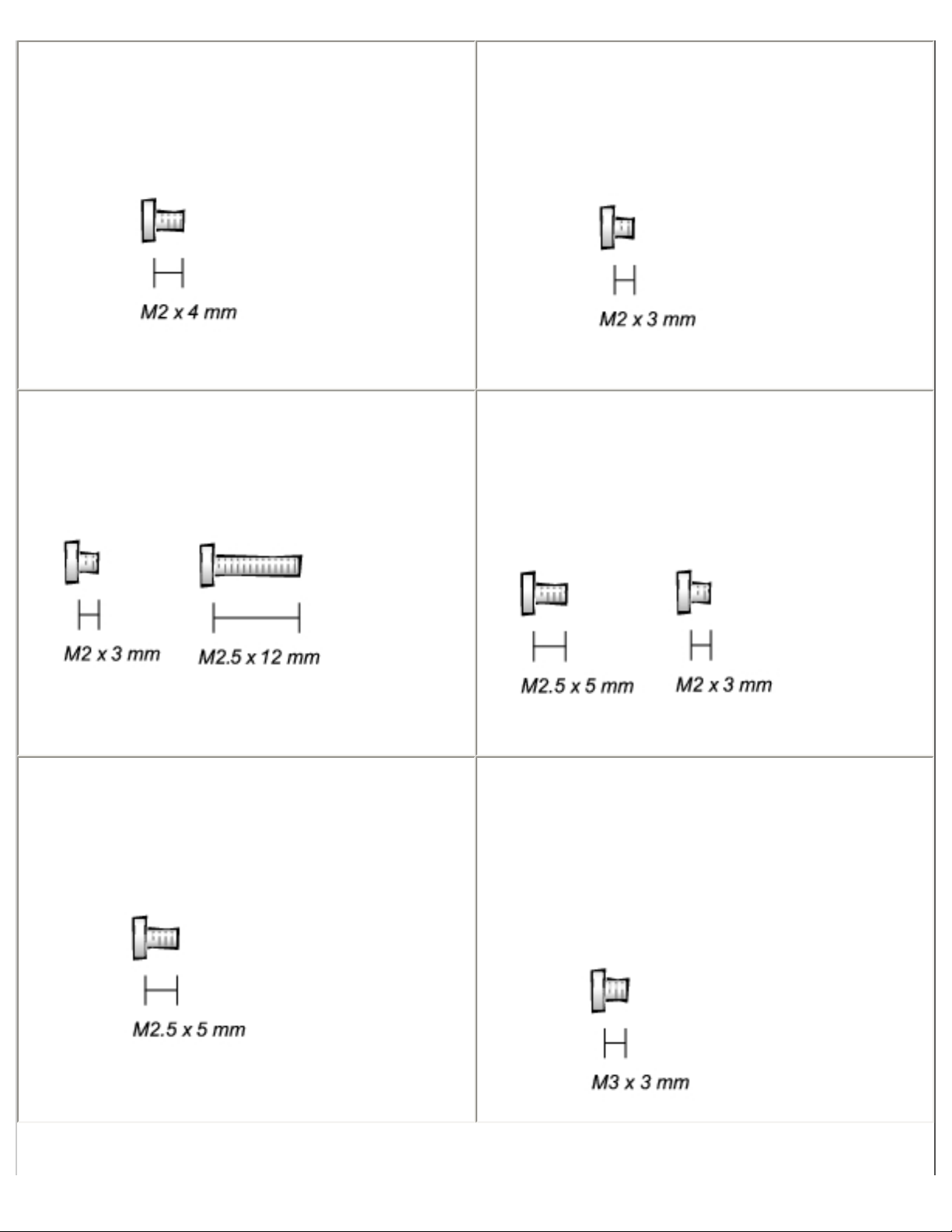
Display Assembly and Flex Cable
Retention Bracket to Top Cover:
(5 each)
Display Assembly EMI Shield Bracket:
(2 each)
Palmrest to Bottom Case Assembly:
(5 each) (3 each)
Hybrid Cooling Fan:
(2 each) (1 each)
System Board to Bottom Case Assembly:
(10 each)
Display Panel to Support Bracket:
(12.1-inch display panel only)
(4 each)
file:///F|/Service%20Manuals/Dell/Latitude/c500-600/begin.htm (5 of 6) [2/28/2004 7:53:27 AM]
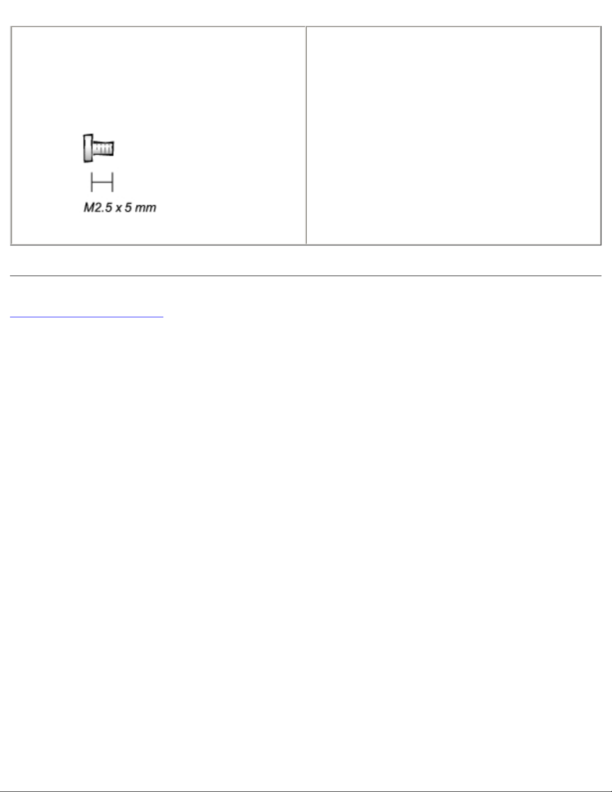
Before You Begin : Dell Latitude C600/C500 Series Service Manual
Display Assembly Latch:
(2 each for 14.1-inch XGA display panels)
Back to Contents Page
file:///F|/Service%20Manuals/Dell/Latitude/c500-600/begin.htm (6 of 6) [2/28/2004 7:53:27 AM]
Removing and Replacing Parts : Dell Latitude C600/C500 Series Service Manual
Back to Contents Page
Removing and Replacing Parts
Dell™ Latitude™ C600/C500 Series Service Manual
Components
Hard Drive
Memory Module
Mini-PCI Card Assembly
Keyboard Assembly
Removing the Display Assembly
Display Assembly Latch
Hinge Covers
Palmrest Assembly
Microprocessor Thermal Cooling Assembly
Hybrid Cooling Fan
Microprocessor Module
Reserve Battery
Speaker Assemblies
System Board Assembly
Battery and Modular Bay Latch Assemblies
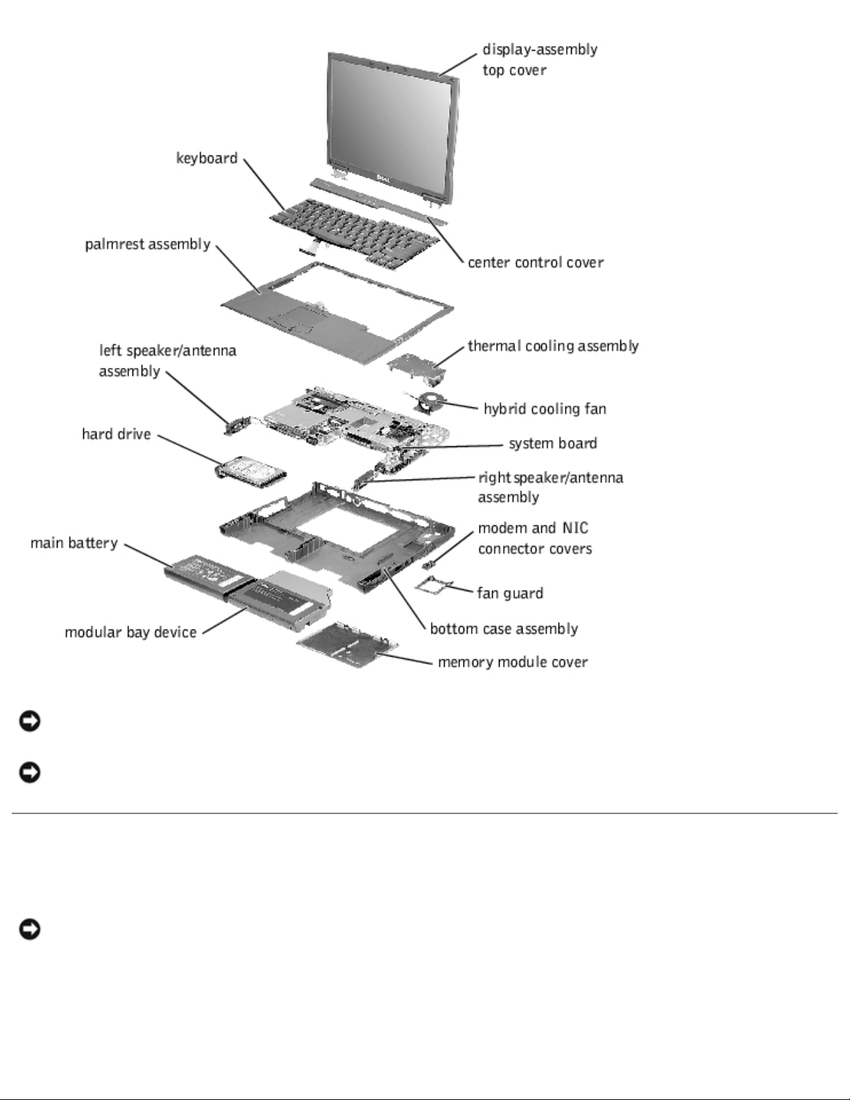
Components
Exploded View
file:///F|/Service%20Manuals/Dell/Latitude/c500-600/remove.htm (1 of 40) [2/28/2004 7:53:33 AM]
Removing and Replacing Parts : Dell Latitude C600/C500 Series Service Manual
NOTICE: Only a certified service technician should perform repairs on your system. Damage due
to servicing that is not authorized by Dell is not covered by your warranty.
NOTICE: Unless otherwise noted, each procedure in this manual assumes that a part can be
replaced by performing the removal procedure in reverse order.
Hard Drive
NOTICE: The hard drive is very sensitive to shock. Handle the assembly by its edges (do not
squeeze the top of the hard drive case), and avoid dropping it.
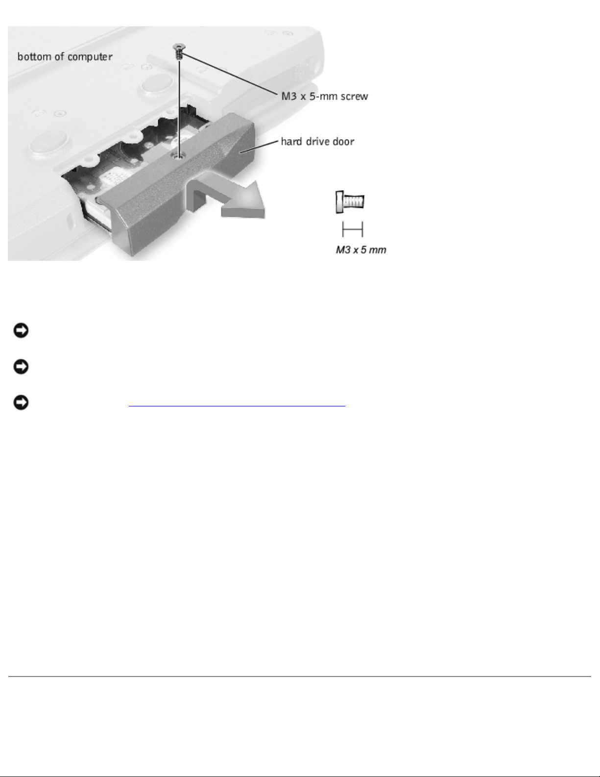
Hard Drive
file:///F|/Service%20Manuals/Dell/Latitude/c500-600/remove.htm (2 of 40) [2/28/2004 7:53:33 AM]
Removing and Replacing Parts : Dell Latitude C600/C500 Series Service Manual
Removing the Hard Drive
NOTICE: Disconnect the computer and any attached devices from electrical outlets, and remove
any installed batteries.
NOTICE: To avoid ESD, ground yourself by using a wrist grounding strap or by touching an
unpainted metal surface on the computer.
NOTICE: Read "Preparing to Work Inside the Computer" before performing the following
procedure.
1. Remove the M3 x 5-mm screw from the hard drive door.
2. Slide the drive door up until the drive assembly tabs disengage from the door slots in the bottom
case assembly.
3. Pull the hard drive straight out of the bottom case assembly.
Replacing the Hard Drive
1. Gently push the hard drive into the drive bay until the drive door is flush with the computer case.
2. Push down on the drive door until it snaps into place.
3. Replace the M3 x 5-mm screw in the hard drive door.
Memory Module
file:///F|/Service%20Manuals/Dell/Latitude/c500-600/remove.htm (3 of 40) [2/28/2004 7:53:33 AM]
Removing and Replacing Parts : Dell Latitude C600/C500 Series Service Manual
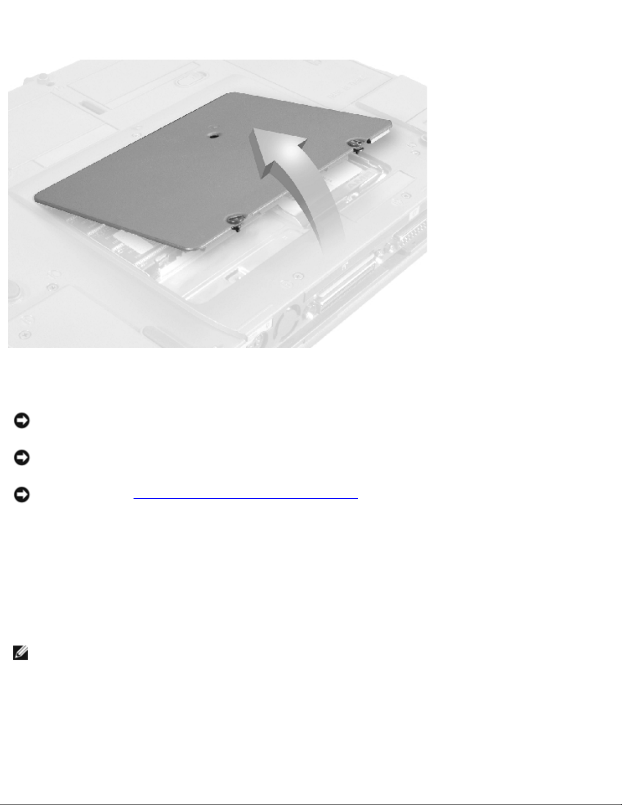
Memory Module Cover
Removing the Memory Module Cover
NOTICE: Disconnect the computer and any attached devices from electrical outlets, and remove
any installed batteries.
NOTICE: To avoid ESD, ground yourself by using a wrist grounding strap or by touching an
unpainted metal surface on the computer.
NOTICE: Read "Preparing to Work Inside the Computer" before performing the following
procedure.
1. Remove the memory module cover:
a. Use a coin or flat-blade screwdriver to release the two captive screws that secure the
memory module cover.
b. Place your finger under the cover at the indentation and lift and slide the cover open.
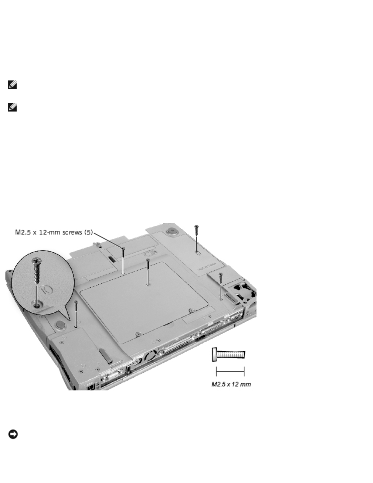
NOTE: The screw labeled with the "circle K" in the middle of the memory module cover secures the
keyboard assembly and does not secure the memory module cover.
Memory Modules
file:///F|/Service%20Manuals/Dell/Latitude/c500-600/remove.htm (4 of 40) [2/28/2004 7:53:33 AM]
Removing and Replacing Parts : Dell Latitude C600/C500 Series Service Manual
Removing the Memory Modules
NOTICE: Disconnect the computer and any attached devices from electrical outlets, and remove
any installed batteries.
NOTICE: To avoid ESD, ground yourself by using a wrist grounding strap or by touching an
unpainted metal surface on the computer.
NOTICE: Read "Preparing to Work Inside the Computer" before performing the following
procedure.
1. Remove the
memory module cover.
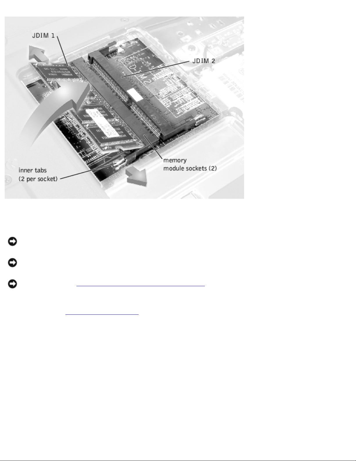
2. To release a memory module from its socket, spread apart the inner tabs of the memory module
socket just far enough for the memory module to disengage from the socket. The module should
pop up slightly.
3. Lift the memory module out of its socket.
Replacing the Memory Modules
1. If you only have one memory module, install it in the socket labeled "JDIM1." Install a second
memory module in the socket labeled "JDIM2."
file:///F|/Service%20Manuals/Dell/Latitude/c500-600/remove.htm (5 of 40) [2/28/2004 7:53:33 AM]
Removing and Replacing Parts : Dell Latitude C600/C500 Series Service Manual
NOTE: Memory modules are keyed, or designed to fit into their sockets, in only one direction.
NOTICE: The memory module must be inserted at a 45-degree angle to avoid damaging the
connector.
2. Align the memory module's edge connector with the slot in the center of the memory module
socket. With the module at a 45-degree angle, press the memory module's edge connector firmly
into the memory module socket.
3. Pivot the memory module down until it clicks into place. If you do not hear a click, remove the
memory module and reinstall it.
4. Insert the tabs on the memory module cover into the bottom case assembly. Rotate the memory
module cover down and tighten the two captive screws.
Mini-PCI Card Assembly
You must remove the optional mini-PCI card assembly before the system board assembly can be
removed. A mini-PCI card assembly may consist of a modem, a NIC, a modem and NIC combination, or a
wireless NIC. A modem, NIC, or modem and NIC combination must be connected to the wiring harness
as appropriate; a wireless NIC must be connected to the system's internal antenna.
Mini-PCI Card Assembly Using Interface Cables
Mini PCI Wireless NIC Assembly Using Antenna Cable
file:///F|/Service%20Manuals/Dell/Latitude/c500-600/remove.htm (6 of 40) [2/28/2004 7:53:33 AM]
Removing and Replacing Parts : Dell Latitude C600/C500 Series Service Manual
Removing the Mini-PCI Card Assembly
NOTICE: Disconnect the computer and any attached devices from electrical outlets, and remove
any installed batteries.
NOTICE: To avoid ESD, ground yourself by using a wrist grounding strap or by touching an
unpainted metal surface on the computer.
NOTICE: Read "Preparing to Work Inside the Computer" before performing the following
procedure.
1. Remove the
memory module cover.
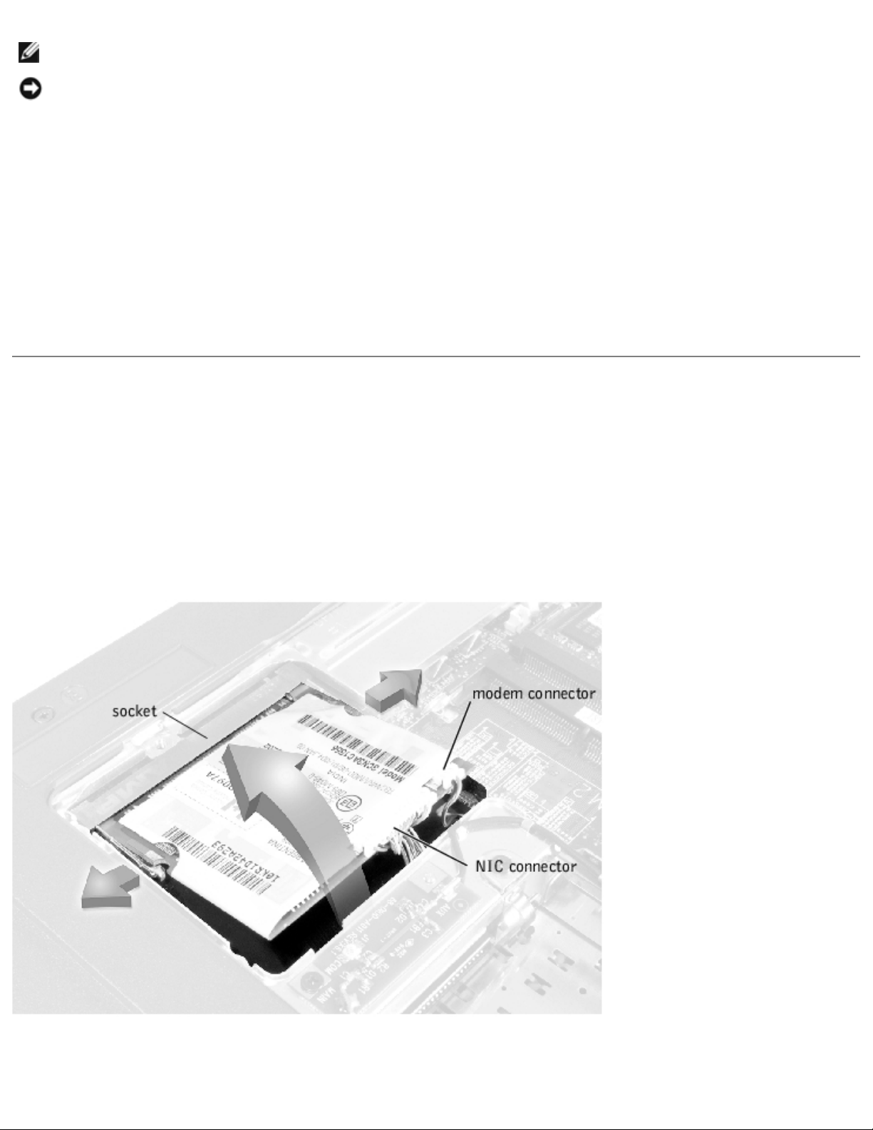
2. To release the mini-PCI card assembly from its socket, spread apart the metal securing tabs until
the assembly pops up slightly.
3. Lift the mini-PCI card assembly out of its socket and disconnect any attached cables.
Replacing the Mini-PCI Card Assembly
NOTICE: The mini-PCI card must be inserted at a 45-degree angle to avoid damaging the
connector.
NOTICE: The mini-PCI card is keyed, or designed to fit into its socket, in only one direction. Do
not force the connection.
1. Align the mini-PCI card with the socket at a 45-degree angle, and press the mini-PCI card firmly
into the socket.
file:///F|/Service%20Manuals/Dell/Latitude/c500-600/remove.htm (7 of 40) [2/28/2004 7:53:33 AM]
Removing and Replacing Parts : Dell Latitude C600/C500 Series Service Manual
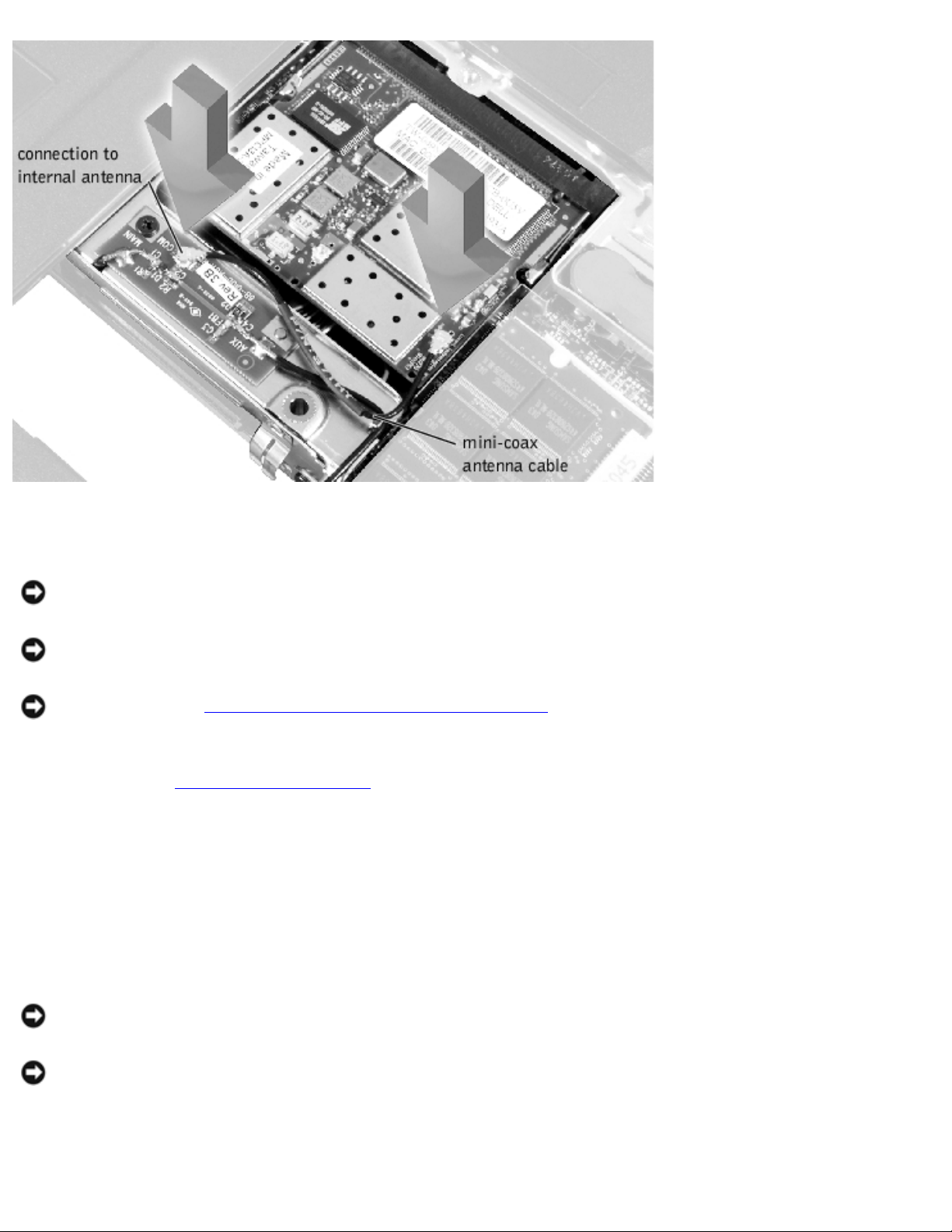
2. Depending on the type of mini-PCI card you are installing, either connect the interface cables to
the mini-PCI card, or connect the mini-coax antenna cable from the mini-PCI card to the internal
antenna.
3. Lower the mini-PCI card until it snaps into the metal securing tabs.
NOTE: If you are installing a wireless NIC, fold and tuck the unused interface cables into the slot so
they do not interfere with the cover.
NOTE: A modem-only mini-PCI card has one connector; place the unused NIC connector under the
mini-PCI card.
4. Replace the memory module cover.
Keyboard Assembly
Removing the Keyboard Screws
Removing the Keyboard Assembly
NOTICE: Disconnect the computer and any attached devices from electrical outlets, and remove
any installed batteries.
file:///F|/Service%20Manuals/Dell/Latitude/c500-600/remove.htm (8 of 40) [2/28/2004 7:53:33 AM]
 Loading...