

Page 1

Dell Latitude 3500
Service Manual
Regulatory Model: P86F
Regulatory Type: P86F001
Page 2

Notes, cautions, and warnings
NOTE: A NOTE indicates important information that helps you make better use of your product.
CAUTION: A CAUTION indicates either potential damage to hardware or loss of data and tells you how to avoid the problem.
WARNING: A WARNING indicates a potential for property damage, personal injury, or death.
© 2019 Dell Inc. or its subsidiaries. All rights reserved. Dell, EMC, and other trademarks are trademarks of Dell Inc. or its subsidiaries. Other trademarks
may be trademarks of their respective owners.
2019 - 03
Rev. A00
Page 3

Contents
1 Working on your computer............................................................................................................................. 5
Safety instructions.............................................................................................................................................................5
Turning o your computer — Windows 10.....................................................................................................................5
Before working inside your computer..............................................................................................................................6
After working inside your computer.................................................................................................................................6
2 Technology and components..........................................................................................................................7
DDR4....................................................................................................................................................................................7
DDR4 Details.................................................................................................................................................................7
Memory Errors..............................................................................................................................................................8
USB features.......................................................................................................................................................................8
USB 3.0/USB 3.1 Gen 1 (SuperSpeed USB).............................................................................................................8
Speed.............................................................................................................................................................................9
Applications...................................................................................................................................................................9
Compatibility................................................................................................................................................................10
USB Type-C.......................................................................................................................................................................10
Alternate Mode...........................................................................................................................................................10
USB Power Delivery...................................................................................................................................................10
USB Type-C and USB 3.1...........................................................................................................................................10
Intel Optane memory.........................................................................................................................................................11
Enabling Intel Optane memory...................................................................................................................................11
Disabling Intel Optane memory..................................................................................................................................11
Intel UHD Graphics 620...................................................................................................................................................12
Nvidia GeForce MX130 equivalent................................................................................................................................. 12
3 Removing and installing components............................................................................................................13
Recommended tools.........................................................................................................................................................13
Secure Digital Card..................................................................................................................................................... 13
Base cover...................................................................................................................................................................14
Battery......................................................................................................................................................................... 19
Hard drive....................................................................................................................................................................23
IO board.......................................................................................................................................................................27
Touchpad..................................................................................................................................................................... 31
Memory modules........................................................................................................................................................37
WLAN card................................................................................................................................................................. 39
Solid-state drive/Intel Optane memory module......................................................................................................41
Speakers..................................................................................................................................................................... 50
System fan..................................................................................................................................................................54
Heat sink..................................................................................................................................................................... 60
VGA daughterboard...................................................................................................................................................63
Power-button board...................................................................................................................................................67
System board.............................................................................................................................................................. 71
Display assembly.........................................................................................................................................................77
Contents
3
Page 4

Display bezel...............................................................................................................................................................86
Display panel...............................................................................................................................................................90
Display hinges.............................................................................................................................................................96
Display cable............................................................................................................................................................... 98
Camera.......................................................................................................................................................................102
Palm-rest and keyboard assembly..........................................................................................................................106
4 Troubleshooting..........................................................................................................................................108
Enhanced Pre-Boot System Assessment — ePSA diagnostics.............................................................................. 108
Running the ePSA Diagnostics...............................................................................................................................108
Diagnostic LED............................................................................................................................................................... 109
Battery status LED.........................................................................................................................................................109
5 Getting help.................................................................................................................................................111
Contacting Dell.................................................................................................................................................................111
4 Contents
Page 5

Working on your computer
Safety instructions
Prerequisite
Use the following safety guidelines to protect your computer from potential damage and to ensure your personal safety. Unless otherwise
noted, each procedure included in this document assumes that the following conditions exist:
• You have read the safety information that shipped with your computer.
• A component can be replaced or, if purchased separately, installed by performing the removal procedure in reverse order.
About this task
WARNING: Disconnect all power sources before opening the computer cover or panels. After you nish working inside the
computer, replace all covers, panels, and screws before connecting to the power source.
WARNING: Before working inside your computer, read the safety information that shipped with your computer. For additional
safety best practices information, see the Regulatory Compliance Homepage
CAUTION: Many repairs may only be done by a certied service technician. You should only perform troubleshooting and simple
repairs as authorized in your product documentation, or as directed by the online or telephone service and support team.
Damage due to servicing that is not authorized by Dell is not covered by your warranty. Read and follow the safety instructions
that came with the product.
CAUTION: To avoid electrostatic discharge, ground yourself by using a wrist grounding strap or by periodically touching an
unpainted metal surface at the same time as touching a connector on the back of the computer.
CAUTION: Handle components and cards with care. Do not touch the components or contacts on a card. Hold a card by its
edges or by its metal mounting bracket. Hold a component such as a processor by its edges, not by its pins.
CAUTION: When you disconnect a cable, pull on its connector or on its pull-tab, not on the cable itself. Some cables have
connectors with locking tabs; if you are disconnecting this type of cable, press in on the locking tabs before you disconnect the
cable. As you pull connectors apart, keep them evenly aligned to avoid bending any connector pins. Also, before you connect a
cable, ensure that both connectors are correctly oriented and aligned.
NOTE: The color of your computer and certain components may appear dierently than shown in this document.
1
Turning o your computer — Windows 10
About this task
CAUTION
remove the side cover.
Steps
1 Click or tap .
2 Click or tap and then click or tap Shut down.
: To avoid losing data, save and close all open les and exit all open programs before you turn o your computer or
: Ensure that the computer and all attached devices are turned o. If your computer and attached devices did not
NOTE
automatically turn o when you shut down your operating system, press and hold the power button for about 6 seconds
to turn them o.
Working on your computer 5
Page 6

Before working inside your computer
About this task
To avoid damaging your computer, perform the following steps before you begin working inside the computer.
Steps
1 Ensure that you follow the Safety Instruction.
2 Ensure that your work surface is at and clean to prevent the computer cover from being scratched.
3 Turn o your computer.
4 Disconnect all network cables from the computer.
CAUTION: To disconnect a network cable, rst unplug the cable from your computer and then unplug the cable from
the network device.
5 Disconnect your computer and all attached devices from their electrical outlets.
6 Press and hold the power button while the computer is unplugged to ground the system board.
NOTE: To avoid electrostatic discharge, ground yourself by using a wrist grounding strap or by periodically touching an
unpainted metal surface at the same time as touching a connector on the back of the computer.
After working inside your computer
About this task
After you complete any replacement procedure, ensure that you connect any external devices, cards, and cables before turning on your
computer.
Steps
1 Connect any telephone or network cables to your computer.
CAUTION
computer.
2 Connect your computer and all attached devices to their electrical outlets.
3 Turn on your computer.
4 If required, verify that the computer works correctly by running ePSA diagnostics.
: To connect a network cable, rst plug the cable into the network device and then plug it into the
6
Working on your computer
Page 7
2
Technology and components
DDR4
DDR4 (double data rate fourth generation) memory is a higher-speed successor to the DDR2 and DDR3 technologies and allows up to 512
GB in capacity, compared to the DDR3's maximum of 128 GB per DIMM. DDR4 synchronous dynamic random-access memory is keyed
dierently from both SDRAM and DDR to prevent the user from installing the wrong type of memory into the system.
DDR4 needs 20 percent less or just 1.2 volts, compared to DDR3 which requires 1.5 volts of electrical power to operate. DDR4 also supports
a new, deep power-down mode that allows the host device to go into standby without needing to refresh its memory. Deep power-down
mode is expected to reduce standby power consumption by 40 to 50 percent.
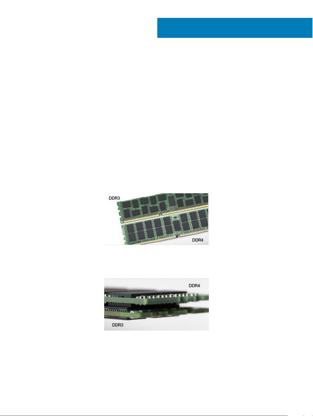
DDR4 Details
There are subtle dierences between DDR3 and DDR4 memory modules, as listed below.
Key notch dierence
The key notch on a DDR4 module is in a dierent location from the key notch on a DDR3 module. Both notches are on the insertion edge
but the notch location on the DDR4 is slightly dierent, to prevent the module from being installed into an incompatible board or platform.
Figure 1. Notch dierence
Increased thickness
DDR4 modules are slightly thicker than DDR3, to accommodate more signal layers.
Figure 2. Thickness dierence
Curved edge
DDR4 modules feature a curved edge to help with insertion and alleviate stress on the PCB during memory installation.
Technology and components 7
Page 8
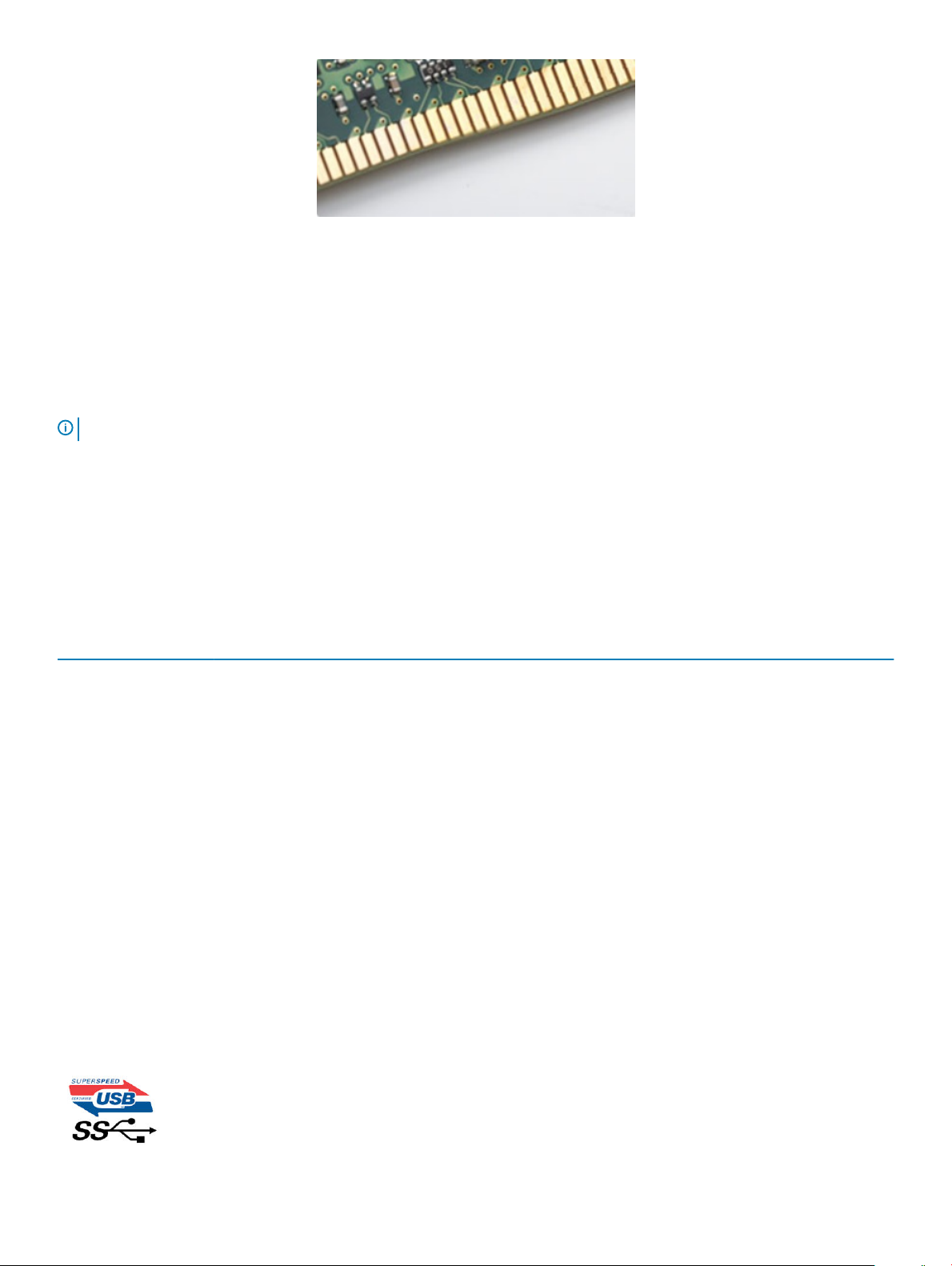
Figure 3. Curved edge
Memory Errors
Memory errors on the system display the new ON-FLASH-FLASH or ON-FLASH-ON failure code. If all memory fails, the LCD does not
turn on. Troubleshoot for possible memory failure by trying known good memory modules in the memory connectors on the bottom of the
system or under the keyboard, as in some portable systems.
NOTE: The DDR4 memory is imbedded in board and not a replaceable DIMM as shown and referred.
USB features
Universal Serial Bus, or USB, was introduced in 1996. It dramatically simplied the connection between host computers and peripheral
devices like mice, keyboards, external drivers, and printers.
Let's take a quick look on the USB evolution referencing to the table below.
Table 1. USB evolution
Type Data Transfer Rate Category Introduction Year
USB 2.0 480 Mbps High Speed 2000
USB 3.0/USB 3.1 Gen 1 5 Gbps Super Speed 2010
USB 3.1 Gen 2 10 Gbps Super Speed 2013
USB 3.0/USB 3.1 Gen 1 (SuperSpeed USB)
For years, the USB 2.0 has been rmly entrenched as the de facto interface standard in the PC world with about 6 billion devices sold, and
yet the need for more speed grows by ever faster computing hardware and ever greater bandwidth demands. The USB 3.0/USB 3.1 Gen 1
nally has the answer to the consumers' demands with a theoretically 10 times faster than its predecessor. In a nutshell, USB 3.1 Gen 1
features are as follows:
• Higher transfer rates (up to 5 Gbps)
• Increased maximum bus power and increased device current draw to better accommodate power-hungry devices
• New power management features
• Full-duplex data transfers and support for new transfer types
• Backward USB 2.0 compatibility
• New connectors and cable
The topics below cover some of the most commonly asked questions regarding USB 3.0/USB 3.1 Gen 1.
Technology and components
8
Page 9
Speed
Currently, there are 3 speed modes dened by the latest USB 3.0/USB 3.1 Gen 1 specication. They are Super-Speed, Hi-Speed and Full-
Speed. The new SuperSpeed mode has a transfer rate of 4.8Gbps. While the specication retains Hi-Speed, and Full-Speed USB mode,
commonly known as USB 2.0 and 1.1 respectively, the slower modes still operate at 480Mbps and 12Mbps respectively and are kept to
maintain backward compatibility.
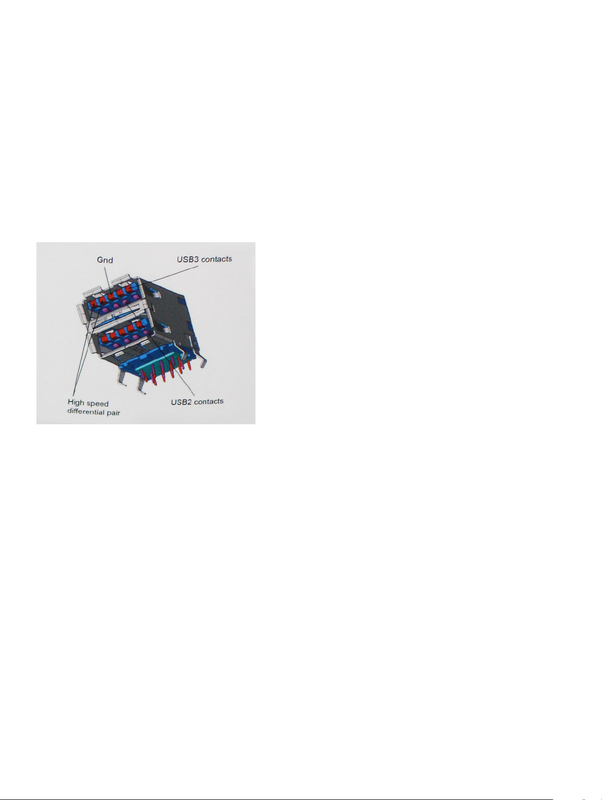
USB 3.0/USB 3.1 Gen 1 achieves the much higher performance by the technical changes below:
• An additional physical bus that is added in parallel with the existing USB 2.0 bus (refer to the picture below).
• USB 2.0 previously had four wires (power, ground, and a pair for dierential data); USB 3.0/USB 3.1 Gen 1 adds four more for two pairs
of dierential signals (receive and transmit) for a combined total of eight connections in the connectors and cabling.
• USB 3.0/USB 3.1 Gen 1 utilizes the bidirectional data interface, rather than USB 2.0's half-duplex arrangement. This gives a 10-fold
increase in theoretical bandwidth.
With today's ever increasing demands placed on data transfers with high-denition video content, terabyte storage devices, high megapixel
count digital cameras etc., USB 2.0 may not be fast enough. Furthermore, no USB 2.0 connection could ever come close to the 480Mbps
theoretical maximum throughput, making data transfer at around 320Mbps (40MB/s) — the actual real-world maximum. Similarly, USB
3.0/USB 3.1 Gen 1 connections will never achieve 4.8Gbps. We will likely see a real-world maximum rate of 400MB/s with overheads. At this
speed, USB 3.0/USB 3.1 Gen 1 is a 10x improvement over USB 2.0.
Applications
USB 3.0/USB 3.1 Gen 1 opens up the laneways and provides more headroom for devices to deliver a better overall experience. Where USB
video was barely tolerable previously (both from a maximum resolution, latency, and video compression perspective), it's easy to imagine
that with 5-10 times the bandwidth available, USB video solutions should work that much better. Single-link DVI requires almost 2Gbps
throughput. Where 480Mbps was limiting, 5Gbps is more than promising. With its promised 4.8Gbps speed, the standard will nd its way
into some products that previously weren't USB territory, like external RAID storage systems.
Listed below are some of the available SuperSpeed USB 3.0/USB 3.1 Gen 1 products:
• External Desktop USB 3.0/USB 3.1 Gen 1 Hard Drives
• Portable USB 3.0/USB 3.1 Gen 1 Hard Drives
• USB 3.0/USB 3.1 Gen 1 Drive Docks & Adapters
• USB 3.0/USB 3.1 Gen 1 Flash Drives & Readers
• USB 3.0/USB 3.1 Gen 1 Solid-state Drives
Technology and components
9
Page 10

• USB 3.0/USB 3.1 Gen 1 RAIDs
• Optical Media Drives
• Multimedia Devices
• Networking
• USB 3.0/USB 3.1 Gen 1 Adapter Cards & Hubs
Compatibility
The good news is that USB 3.0/USB 3.1 Gen 1 has been carefully planned from the start to peacefully co-exist with USB 2.0. First of all,
while USB 3.0/USB 3.1 Gen 1 species new physical connections and thus new cables to take advantage of the higher speed capability of
the new protocol, the connector itself remains the same rectangular shape with the four USB 2.0 contacts in the exact same location as
before. Five new connections to carry receive and transmitted data independently are present on USB 3.0/USB 3.1 Gen 1 cables and only
come into contact when connected to a proper SuperSpeed USB connection.
Windows 8/10 will be bringing native support for USB 3.1 Gen 1 controllers. This is in contrast to previous versions of Windows, which
continue to require separate drivers for USB 3.0/USB 3.1 Gen 1 controllers.
Microsoft announced that Windows 7 would have USB 3.1 Gen 1 support, perhaps not on its immediate release, but in a subsequent Service
Pack or update. It is not out of the question to think that following a successful release of USB 3.0/USB 3.1 Gen 1 support in Windows 7,
SuperSpeed support would trickle down to Vista. Microsoft has conrmed this by stating that most of their partners share the opinion that
Vista should also support USB 3.0/USB 3.1 Gen 1.
USB Type-C
USB Type-C is a new, tiny physical connector. The connector itself can support various exciting new USB standard like USB 3.1 and USB
power delivery (USB PD).
Alternate Mode
USB Type-C is a new connector standard that's very small. It's about a third the size of an old USB Type-A plug. This is a single connector
standard that every device should be able to use. USB Type-C ports can support a variety of dierent protocols using “alternate modes,”
which allows you to have adapters that can output HDMI, VGA, DisplayPort, or other types of connections from that single USB port
USB Power Delivery
The USB PD specication is also closely intertwined with USB Type-C. Currently, smartphones, tablets, and other mobile devices often use
a USB connection to charge. A USB 2.0 connection provides up to 2.5 watts of power — that'll charge your phone, but that's about it. A
laptop might require up to 60 watts, for example. The USB Power Delivery specication ups this power delivery to 100 watts. It's bidirectional, so a device can either send or receive power. And this power can be transferred at the same time the device is transmitting
data across the connection.
This could spell the end of all those proprietary laptop charging cables, with everything charging via a standard USB connection. You could
charge your laptop from one of those portable battery packs you charge your smartphones and other portable devices from today. You
could plug your laptop into an external display connected to a power cable, and that external display would charge your laptop as you used
it as an external display — all via the one little USB Type-C connection. To use this, the device and the cable have to support USB Power
Delivery. Just having a USB Type-C connection doesn't necessarily mean they do.
USB Type-C and USB 3.1
USB 3.1 is a new USB standard. USB 3's theoretical bandwidth is 5 Gbps, while USB 3.1 Gen2 is10Gbps . That's double the bandwidth, as
fast as a rst-generation Thunderbolt connector. USB Type-C isn't the same thing as USB 3.1. USB Type-C is just a connector shape, and
Technology and components
10
Page 11

the underlying technology could just be USB 2 or USB 3.0. In fact, Nokia's N1 Android tablet uses a USB Type-C connector, but underneath
it's all USB 2.0 — not even USB 3.0. However, these technologies are closely related.
Intel Optane memory
Intel Optane memory functions only as a storage accelerator. It neither replaces nor adds to the memory (RAM) installed on your computer.
NOTE: Intel Optane memory is supported on computers that meet the following requirements:
• 7th Generation or higher Intel Core i3/i5/i7 processor
• Windows 10 64-bit version or higher
• Intel Rapid Storage Technology driver version 15.9.1.1018 or higher
Table 2. Intel Optane memory specications
Feature Specications
Interface PCIe 3x2 NVMe 1.1
Connector M.2 card slot (2230/2280)
Congurations supported
Capacity 16 GB
• 7th Generation or higher Intel Core i3/i5/i7 processor
• Windows 10 64-bit version or higher
• Intel Rapid Storage Technology driver version 15.9.1.1018 or
higher
Enabling Intel Optane memory
1 On the taskbar, click the search box, and type "Intel Rapid Storage Technology".
2 Click Intel Rapid Storage Technology.
3 On the Status tab, click Enable to enable the Intel Optane memory.
4 On the warning screen, select a compatible fast drive, and then click Yes to continue enabling Intel Optane memory.
5 Click Intel Optane memory > Reboot to enable the Intel Optane memory.
NOTE
: Applications may take up to three subsequent launches after enablement to see the full performance benets.
Disabling Intel Optane memory
About this task
CAUTION
blue screen error. The Intel Rapid Storage Technology user interface can be removed without uninstalling the driver.
NOTE: Disabling Intel Optane memory is required before removing the SATA storage device, accelerated by the Intel Optane
memory module, from the computer.
: After disabling Intel Optane memory, do not uninstall the driver for Intel Rapid Storage Technology as it will result in a
Steps
1 On the taskbar, click the search box, and then type "Intel Rapid Storage Technology".
2 Click Intel Rapid Storage Technology. The Intel Rapid Storage Technology window is displayed.
3 On the Intel Optane memory tab, click Disable to disable the Intel Optane memory.
4 Click Yes if you accept the warning.
The disabling progress is displayed.
5 Click Reboot to complete disabling Intel Optane memory and restart your computer.
Technology and components
11
Page 12

Intel UHD Graphics 620
Table 3. Intel UHD Graphics 620 specications
Intel UHD Graphics 620
Bus Type Integrated
Memory Type DDR4
Graphics Level i3/i5/i7: G T2 (UHD 620)
Estimated Maximum Power Consumption (TDP) 15 W (included in the CPU power)
Overlay Planes Yes
Operating Systems Graphics/ Video API Support DirectX 11 (Windows 7/8.1), DirectX 12 (Windows 10), OpenGL 4.3
Maximum Vertical Refresh Rate Up to 85 Hz depending on resolution
Multiple Display Support
On System: eDP (internal), HDMI
Via Optional USB Type-C Port: VGA, DisplayPort
External Connectors
HDMI 1.4b
USB Type–C port
Nvidia GeForce MX130 equivalent
Table 4. Nvidia GeForce MX130
Feature Specications
Graphics memory 2 GB GDDR5
Bus type PCI Express 3.0
Memory Interface GDDR5
Clock Speeds 1122 - 1242 (Boost) MHz
Maximum Color Depth N/A
Maximum Vertical Refresh Rate N/A
Operating Systems Graphics/ Video API Support Windows 10/ DX 12/ OGL4.5
Supported Resolutions and Max Refresh Rates (Hz) N/A
specications
Numbers of Display Support No display output from MX130
12 Technology and components
Page 13
Removing and installing components
Recommended tools
The procedures in this document require the following tools:
• Phillips #0 screwdriver
• Phillips #1 screwdriver
• Plastic scribe
NOTE: The #0 screw driver is for screws 0-1 and the #1 screw driver is for screws 2-4
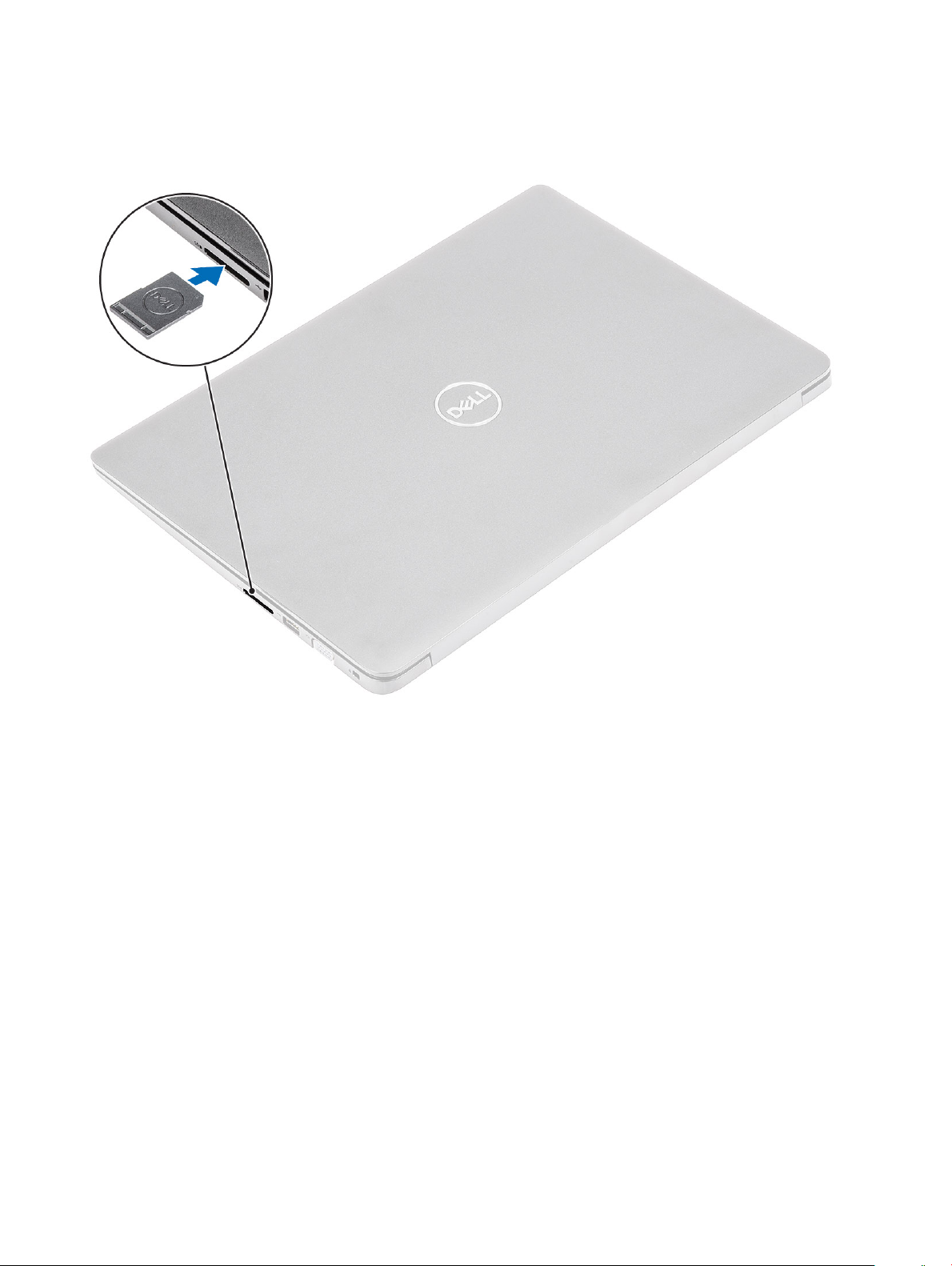
Secure Digital Card
Removing the Secure Digital card
Prerequisite
1 Follow the procedure in Before working inside your computer
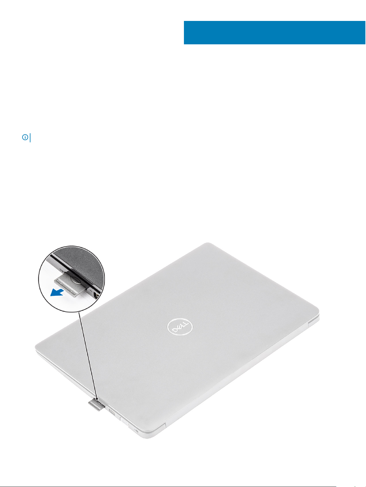
Steps
1 Push the secure digital card to release it from the computer.
2 Slide the secure digital card out of the computer.
3
Removing and installing components 13
Page 14
Installing the Secure Digital card
1 Slide the secure digital into the slot until it clicks into place.
2 Follow the procedures in After working inside your computer.
Base cover
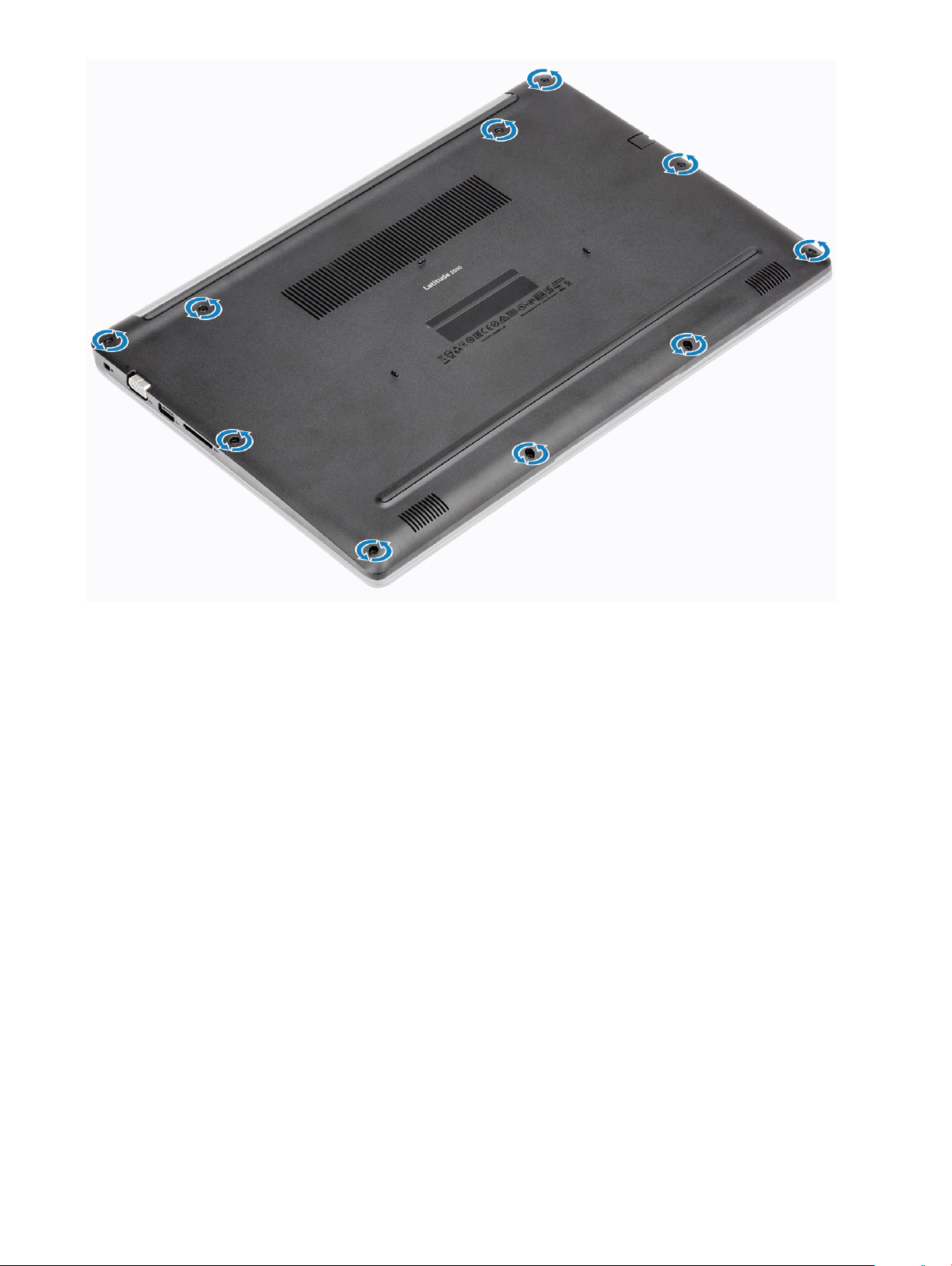
Removing the base cover
Prerequisites
1 Follow the procedure in before working inside your computer
2 Remove the SD memory card
Steps
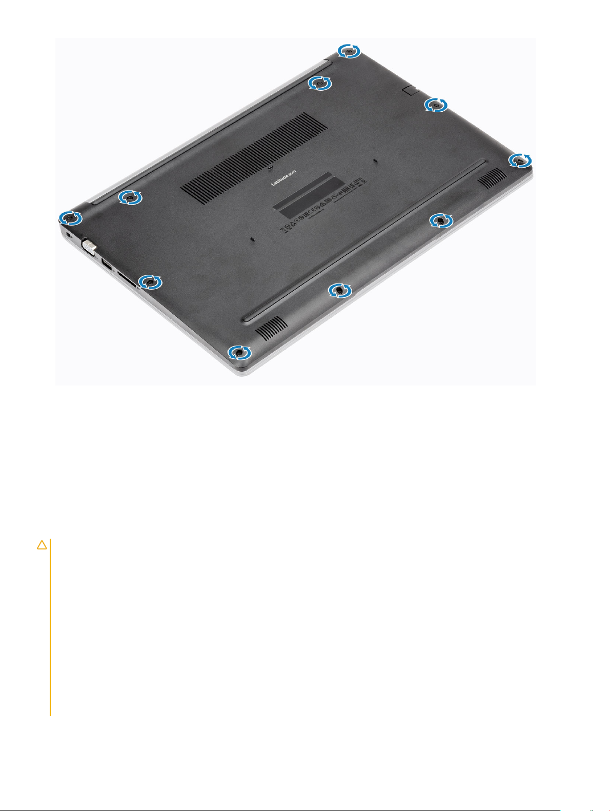
1 Loosen the ten captive screws that secure the base cover to the palmrest and keyboard assembly.
Removing and installing components
14
Page 15
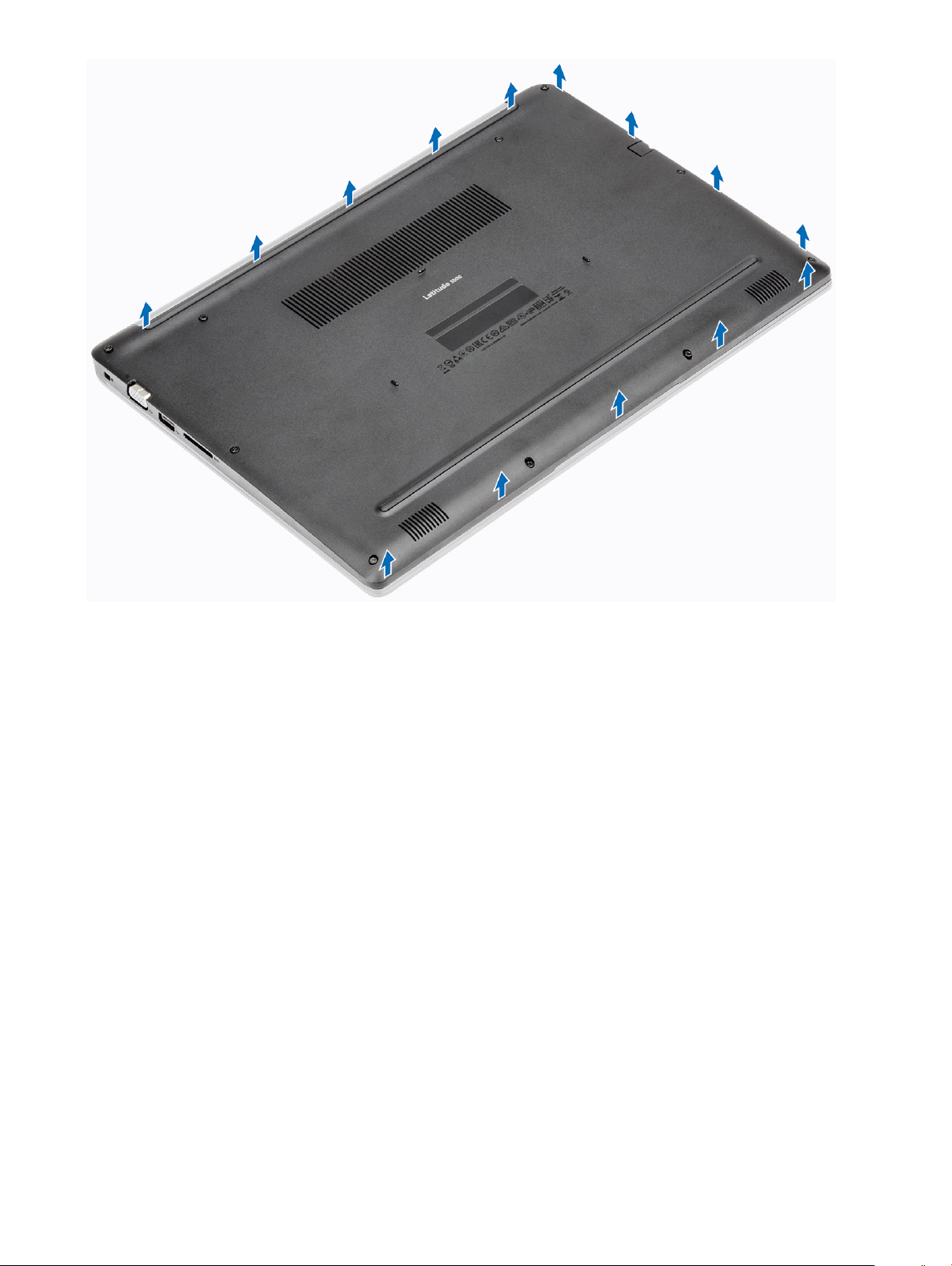
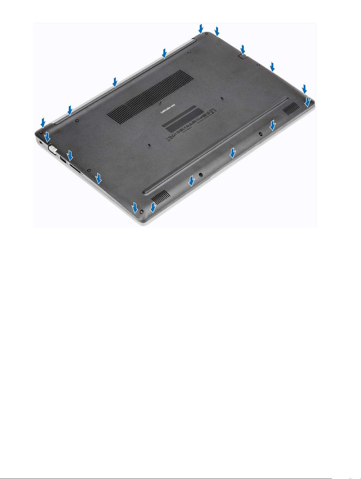
2 Pry the base cover and continue to open the right side of the base cover.
Removing and installing components
15
Page 16
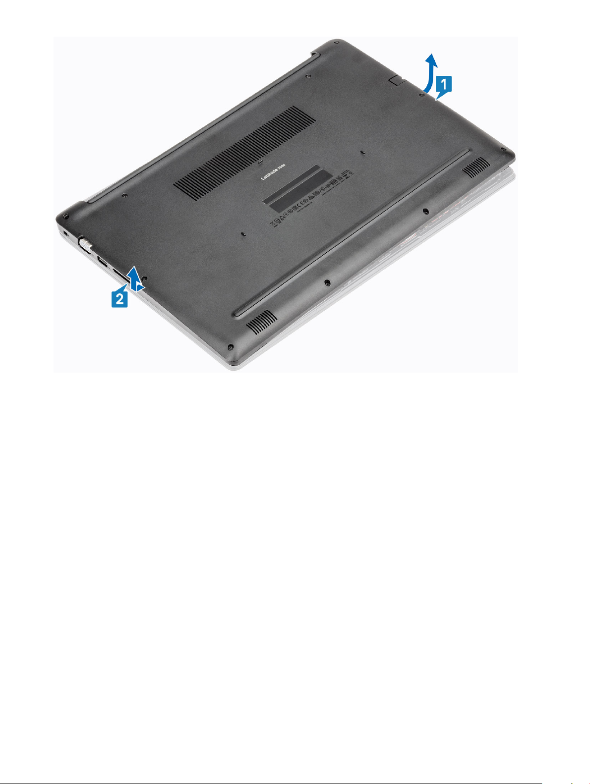
3 Lift the right side of the base cover [1], and remove it o the palmrest and keyboard assembly [2].
16
Removing and installing components
Page 17
Installing the base cover
Steps
1 Place the base cover on the palmrest and keyboard assembly [1].
Removing and installing components
17
Page 18
2 Tighten the ten captive screws that secure the base cover to the palmrest and keyboard assembly.
18
Removing and installing components
Page 19
Next steps
1 Replace the SD memory card
2 Follow the procedure in after working inside your computer
Battery
Lithium-ion battery precautions
CAUTION
• Exercise caution when handling Lithium-ion batteries.
• Discharge the battery as much as possible before removing it from the system. This can be done by disconnecting the AC adapter
• Do not crush, drop, mutilate, or penetrate the battery with foreign objects.
• Do not expose the battery to high temperatures, or disassemble battery packs and cells.
• Do not apply pressure to the surface of the battery.
• Do not bend the battery.
• Do not use tools of any kind to pry on or against the battery.
• If a battery gets stuck in a device as a result of swelling, do not try to free it as puncturing, bending, or crushing a Lithium-ion
• Always purchase genuine batteries from https://www.dell.com or authorized Dell partners and re-sellers.
:
from the system to allow the battery to drain.
battery can be dangerous. In such an instance, the entire system should be replaced. Contact https://www.dell.com/support for
assistance and further instructions.
Removing and installing components 19
Page 20
Removing the battery
Prerequisites
1 Follow the procedure in before working inside your computer
2 Remove the SD memory card
3 Remove the base cover
Steps
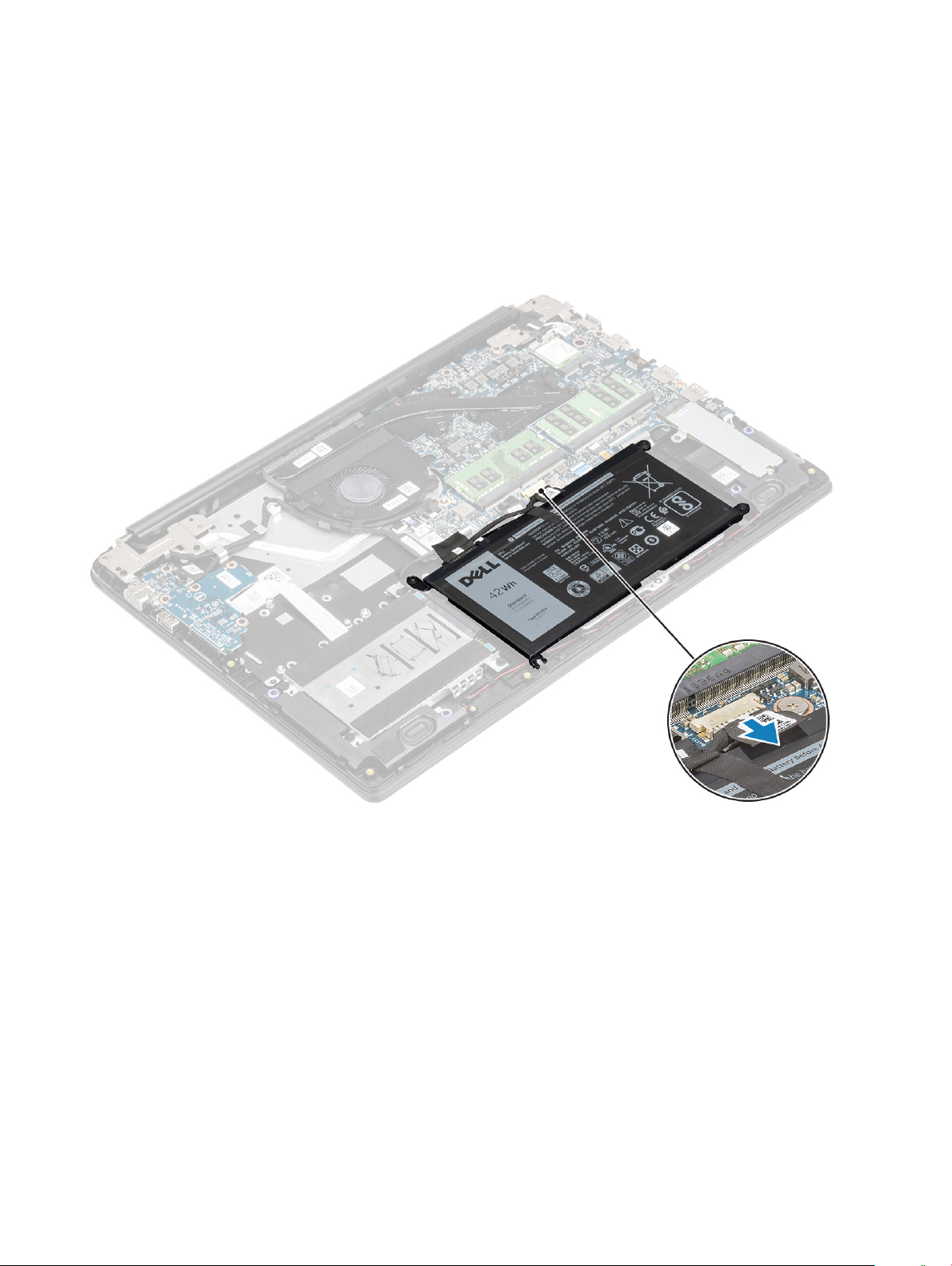
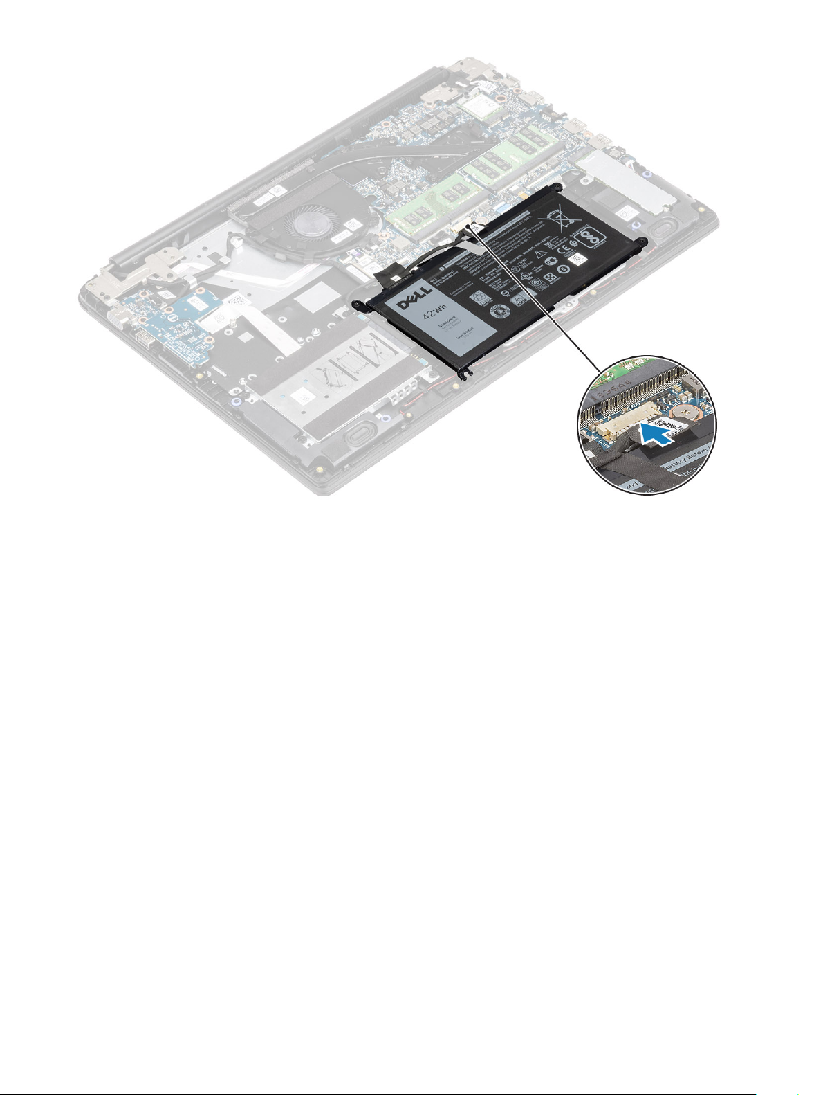
1 Disconnect the battery cable from the system board.
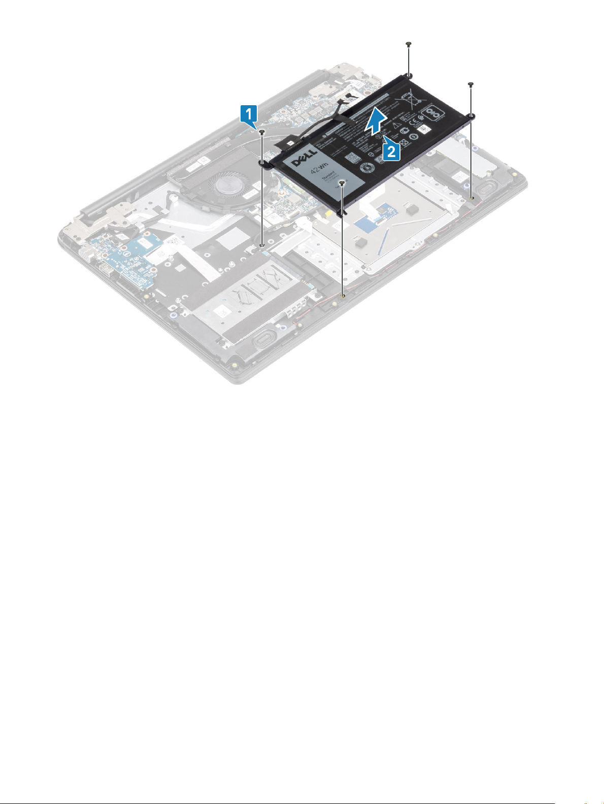
2 Remove the four (M2x3) screws that secure the battery to the palmrest and keyboard assembly [1].
3 Lift the battery o the palmrest and keyboard assembly [2].
20
Removing and installing components
Page 21
Installing the battery
Steps
1 Align the screw holes on the battery with the screw holes on the palmrest and keyboard assembly [1].
2 Replace the four (M2x3) screws that secure the battery to the palmrest and keyboard assembly [2].
Removing and installing components
21
Page 22

3 Connect the battery cable to the system board.
22
Removing and installing components
Page 23
Next steps
1 Replace the base cover
2 Replace the SD memory card
3 Follow the procedure in after working inside your computer
Hard drive
Removing the hard drive assembly
Prerequisites
1 Follow the procedure in before working inside your computer
2 Remove the SD memory card
3 Remove the base cover
4 Remove the battery
Steps
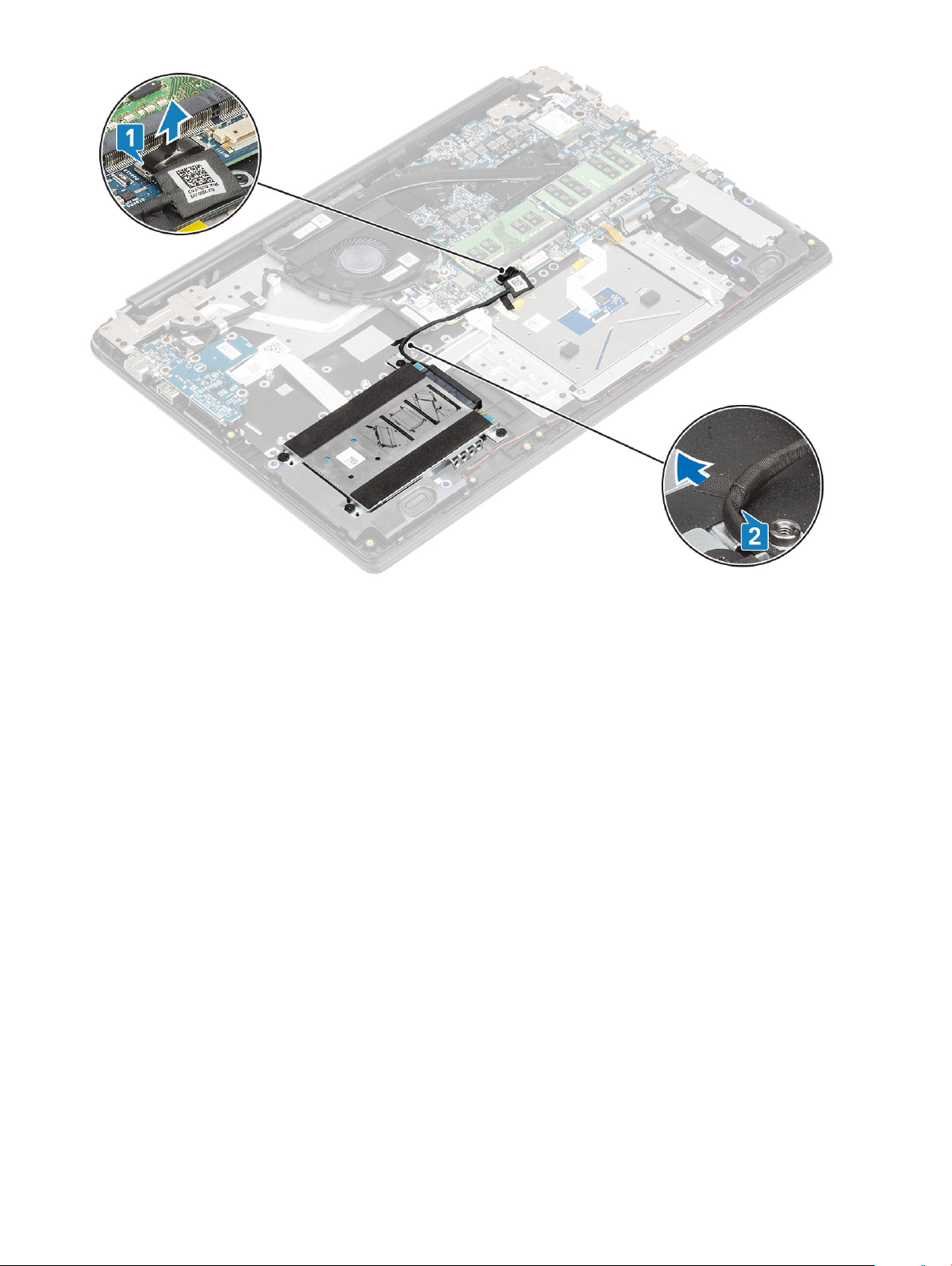
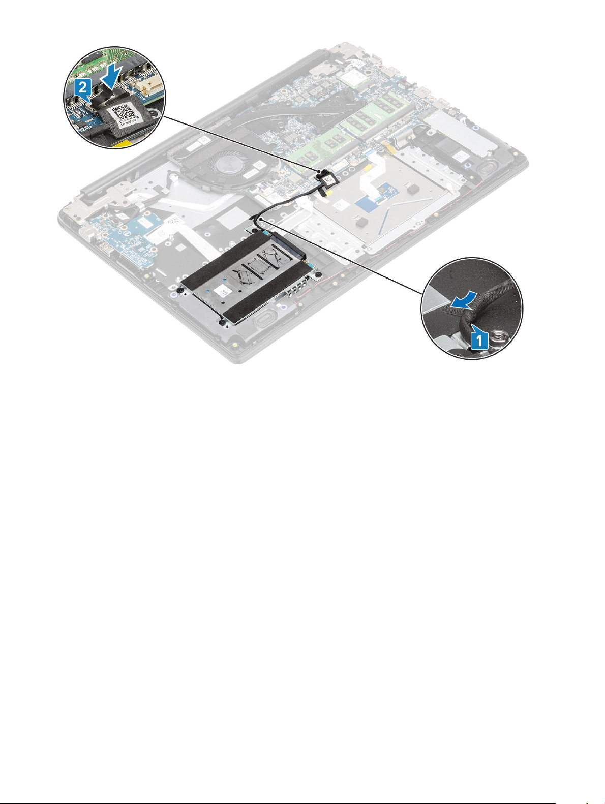
1 Disconnect the hard drive cable from the system board [1].
2 Peel the tape that secures the hard drive cable to the palmrest and keyboard assembly [2].
Removing and installing components
23
Page 24
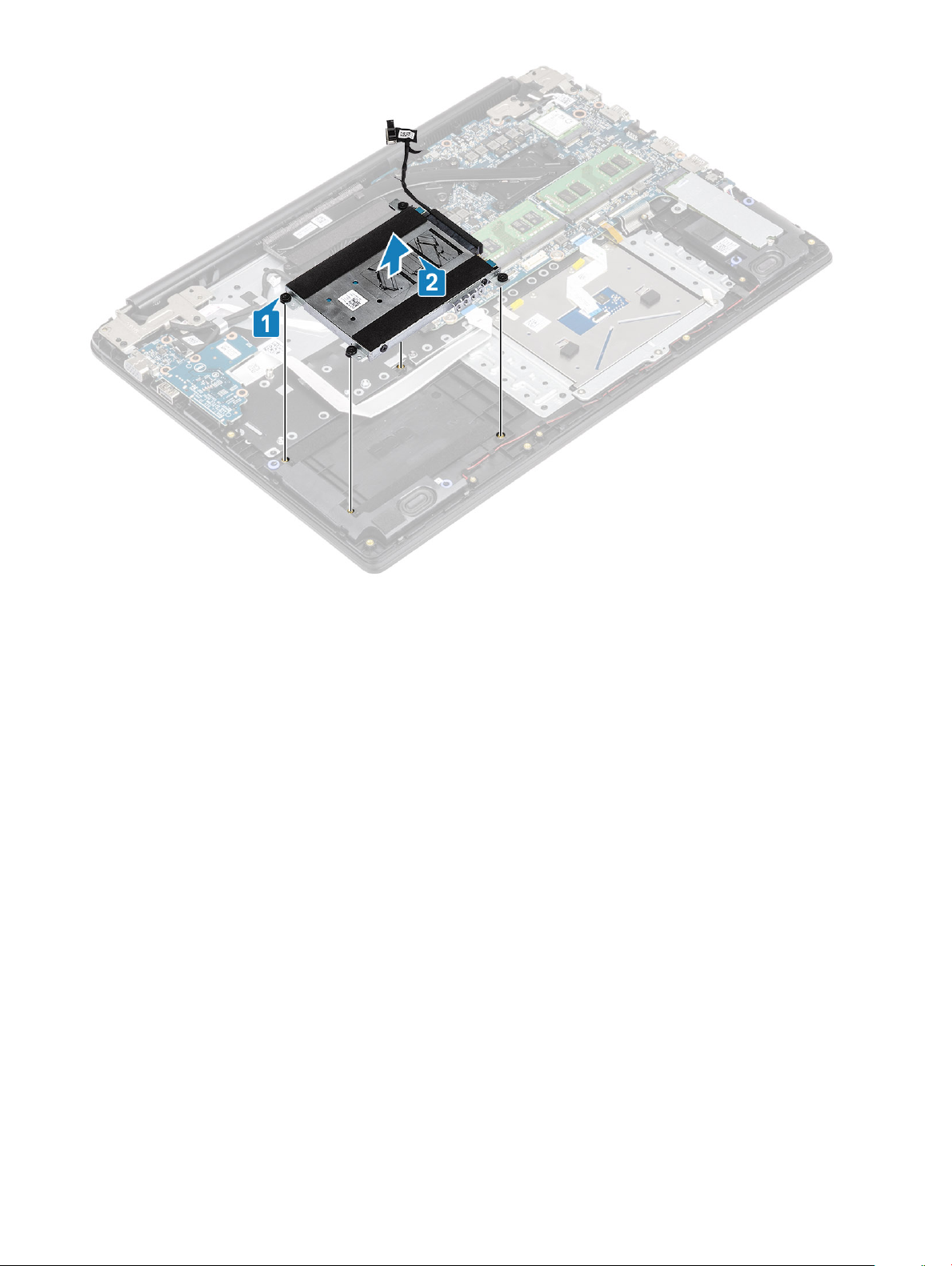
3 Remove the four (M2x4) screws that secure the hard drive assembly to the palmrest and keyboard assembly [1].
4 Lift the hard drive from the slot on the palmrest and keyboard assembly [2].
24
Removing and installing components
Page 25
Installing the hard drive assembly
Steps
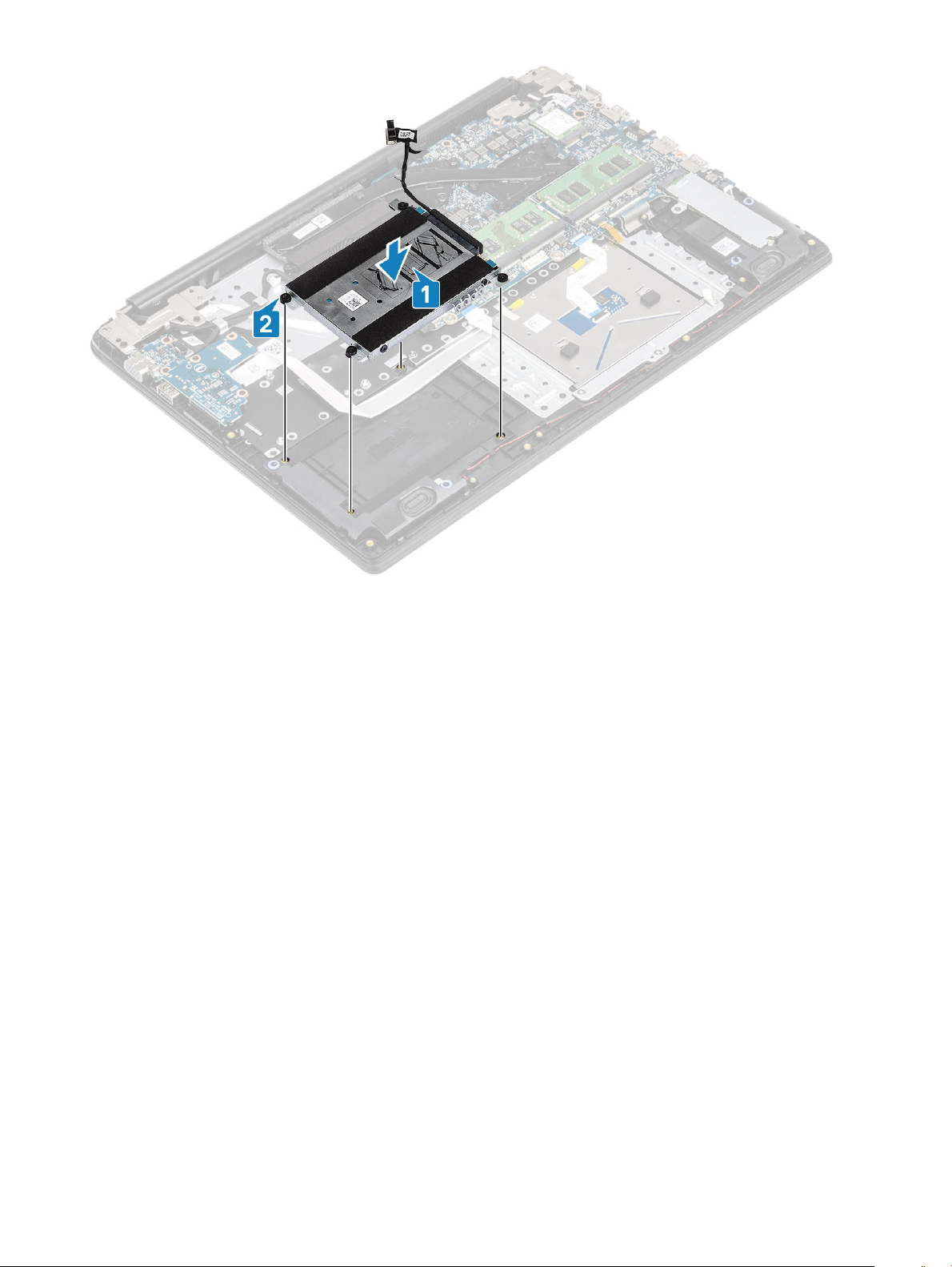
1 Align the screw holes on the hard drive assembly with the screw holes on the palm rest and keyboard assembly [1].
2 Replace the four (M2x4) screws that secure the hard drive assembly to the palm rest and keyboard assembly [2].
Removing and installing components
25
Page 26
3 Adhere the tape that secures the hard drive cable to the palmrest and keyboard assembly [1].
4 Connect the hard drive cable to the system board [2].
26
Removing and installing components
Page 27
Next steps
1 Replace the battery
2 Replace the base cover
3 Replace the SD memory card
4 Follow the procedure in after working inside your computer
IO board
Removing the IO board
Prerequisites
1 Follow the procedure in before working inside your computer
2 Remove the SD memory card
3 Remove the base cover
4 Remove the battery
5 Remove the hard drive assembly
Steps
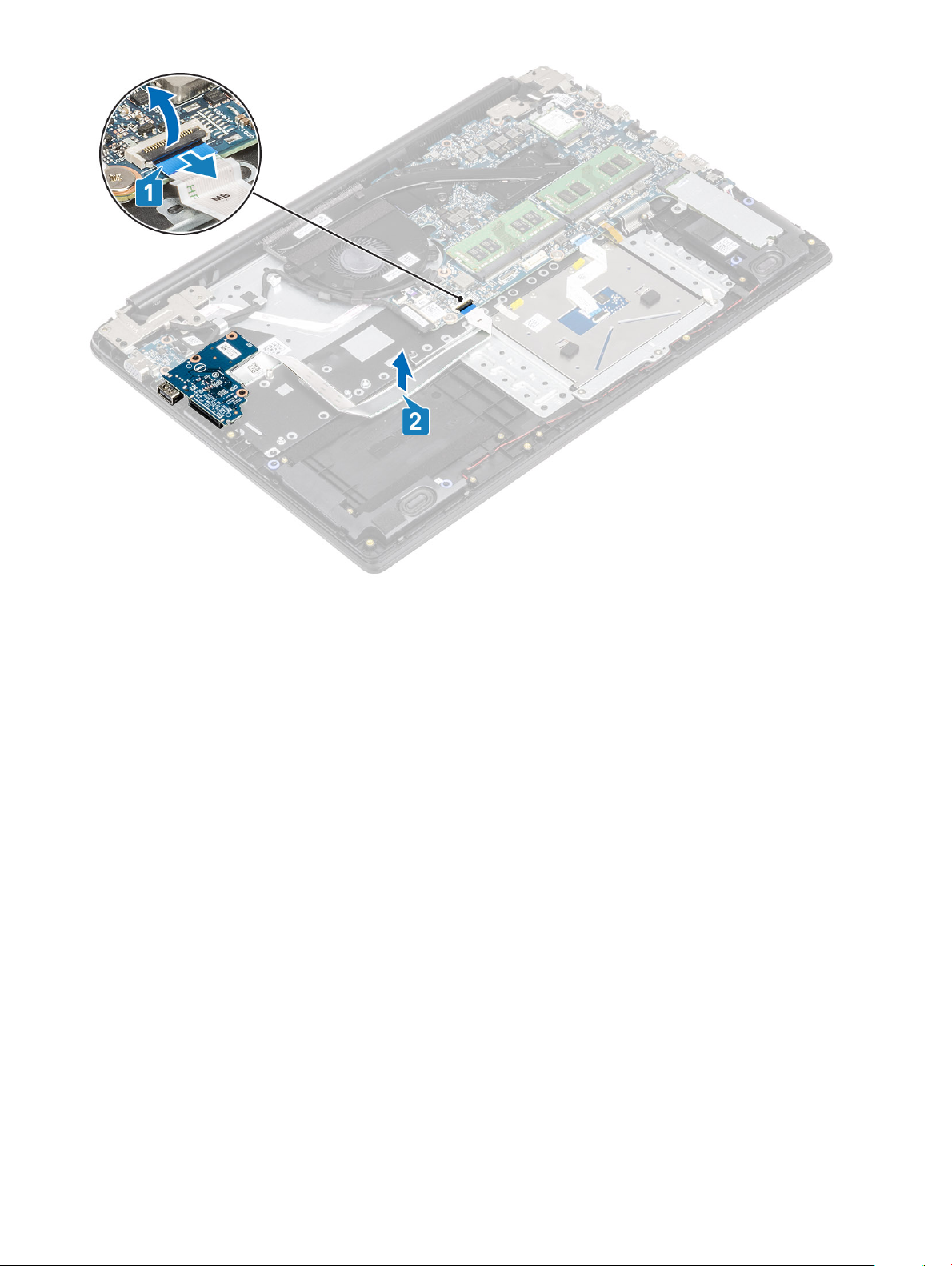
1 Open the latch and disconnect the I/O board cable from the system board [1].
2 Peel the I/O-board cable from the palm rest and keyboard assembly [2].
Removing and installing components
27
Page 28
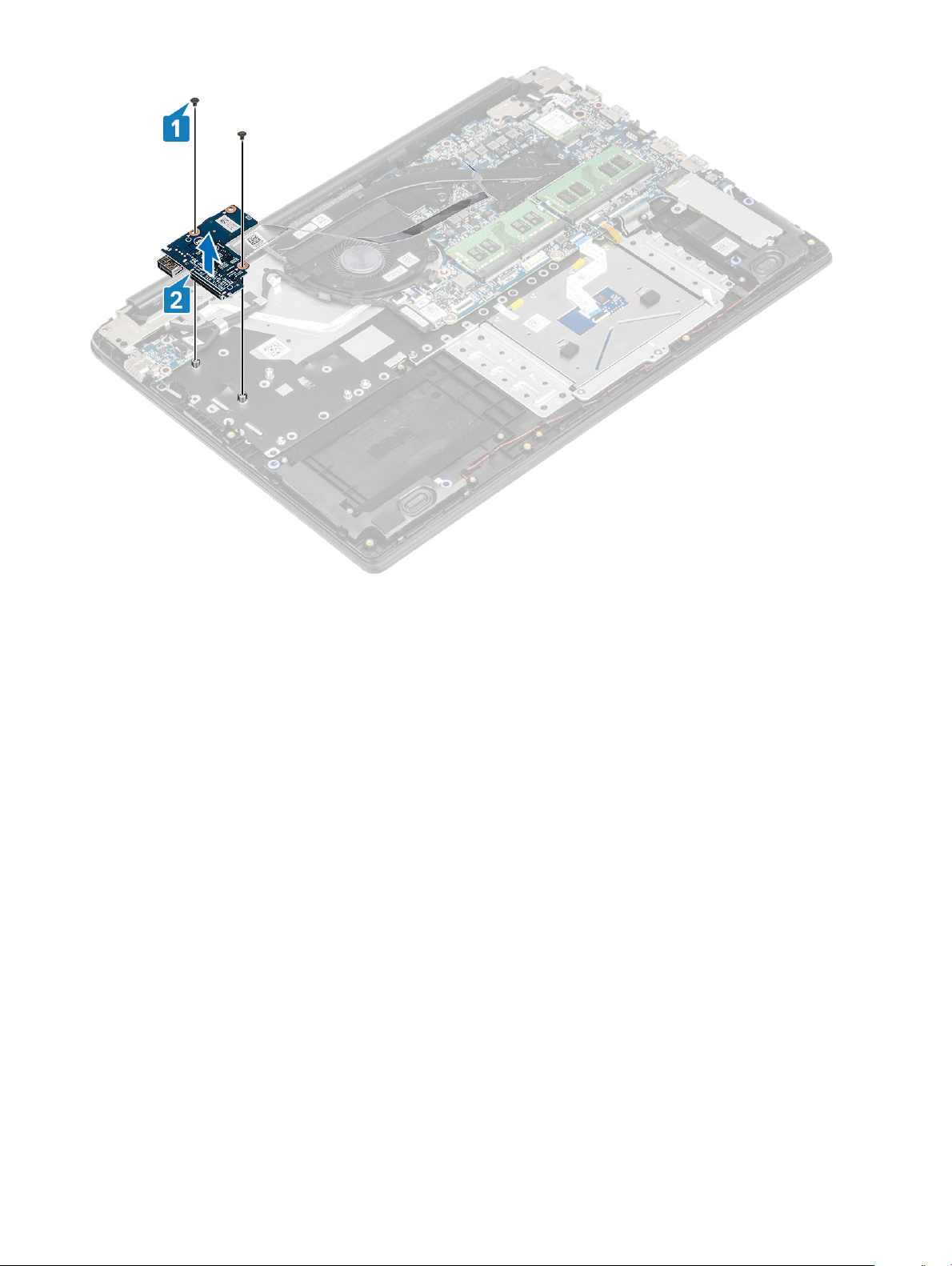
3 Remove the two (M2x3) screws that secure the I/O board to the palm rest and keyboard assembly [1].
4 Lift the I/O board, along with the cable, o the palm rest and keyboard assembly [2].
28
Removing and installing components
Page 29
Installing the IO board
Steps
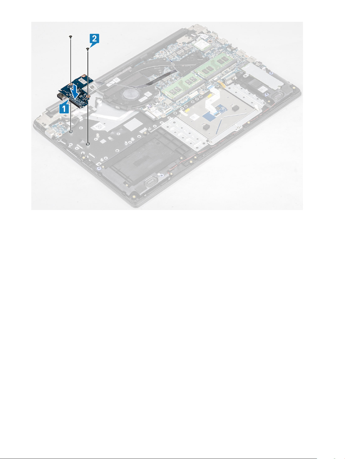
1 Using the alignment posts, place the I/O board on the palm rest and keyboard assembly [1].
2 Replace the two (M2x3) screws that secure the I/O board to the palm rest and keyboard assembly [2].
Removing and installing components
29
Page 30
3 Adhere the I/O board cable to the palm rest and keyboard assembly [1].
4 Connect the I/O board cable to the system board and close the latch to secure the cable [2].
30
Removing and installing components
Page 31

Next steps
1 Replace the hard drive assembly
2 Replace the battery
3 Replace the base cover
4 Replace the SD memory card
5 Follow the procedure in after working inside your computer
Touchpad
Removing the touch pad assembly
Prerequisites
1 Follow the procedure in before working inside your computer
2 Remove the SD memory card
3 Remove the base cover
4 Remove the battery
Steps
1 Remove the three (M2x2) screws that secure the touch pad bracket to the palmrest and keyboard assembly [1].
2 Lift the touch pad bracket o the palmrest and keyboard assembly [2], and peel the tape that secures the bracket to the palmrest.
Removing and installing components
31
Page 32

3 Open the latch and disconnect the touch pad cable from the system board [1].
4 Peel the tape that secures the touch pad to the palmrest and keyboard assembly [2].
32
Removing and installing components
Page 33

5 Remove the four (M2x2) screws that secure the touch pad to the palmrest and keyboard assembly [1].
6 Lift the touch pad o the palmrest and keyboard assembly [2].
Removing and installing components
33
Page 34

Installing the touch pad assembly
About this task
: Ensure that the touch pad is aligned with the guides available on the palm-rest and keyboard assembly, and the gap on
NOTE
either sides of the touch pad is equal.
Steps
1 Place the touch pad into the slot on the palmrest and keyboard assembly [1].
2 Replace the four (M2x2) screws that secure the touch pad to the palmrest and keyboard assembly [2].
34
Removing and installing components
Page 35

3 Adhere the tape that secures the touch pad to the palmrest and keyboard assembly [1].
4 Slide the touch pad cable into its connector on the system board and close the latch to secure the cable [2].
Removing and installing components
35
Page 36

5 Place the touch pad bracket into the slot on the palmrest and keyboard assembly [1].
6 Replace the three screws (M2x2) that secure the touch pad bracket to the palmrest and keyboard assembly [2], and adhere the tape
that secures the bracket to the palmrest.
36
Removing and installing components
Page 37

Next steps
1 Replace the battery
2 Replace the base cover
3 Replace the SD memory card
4 Follow the procedure in after working inside your computer
Memory modules
Removing the memory module
Prerequisites
1 Follow the procedure in before working inside your computer
2 Remove the SD memory card
3 Remove the base cover
4 Remove the battery
Steps
1 Pry the clips securing the memory module until the memory module pops-up [1].
2 Remove the memory module from the memory module slot [2].
Removing and installing components
37
Page 38

Installing the memory module
Steps
1 Align the notch on the memory module with the tab on the memory-module slot.
2 Slide the memory module rmly into the slot at an angle [1].
3 Press the memory module down until the clips secure it [2].
NOTE
: If you do not hear the click, remove the memory module and reinstall it.
38 Removing and installing components
Page 39

Next steps
1 Replace the battery
2 Replace the base cover
3 Replace the SD memory card
4 Follow the procedure in after working inside your computer
WLAN card
Removing the WLAN card
Prerequisites
1 Follow the procedure in before working inside your computer
2 Remove the SD memory card
3 Remove the base cover
4 Remove the battery
Steps
1 Remove the single (M2x3) screw that secures the WLAN card bracket to the system board [1].
2 Slide and remove the WLAN card bracket that secures the WLAN cables [2].
3 Disconnect the WLAN cables from the connectors on the WLAN card [3].
4 Lift the WLAN card away from the connector [4].
Removing and installing components
39
Page 40

Installing the WLAN card
About this task
CAUTION
Steps
1 Insert the WLAN card into the connector on the system board [1].
2 Connect the WLAN cables to the connectors on the WLAN card [2].
3 Place the WLAN card bracket to secure the WLAN cables to the WLAN card [3].
4 Replace the single (M2x3) screw to secure the WLAN bracket to the WLAN card [4].
40
: To avoid damage to the WLAN card, do not place any cables under it.
Removing and installing components
Page 41

Next steps
1 Replace the battery
2 Replace the base cover
3 Replace the SD memory card
4 Follow the procedure in after working inside your computer
Solid-state drive/Intel Optane memory module
Removing the M.2 2280 Solid-state drive or Intel Optane memory—
Optional
Prerequisites
NOTE
: Disable the Intel Optane memory before removing the Intel Optane memory module from your computer. For more
information about disabling the Intel Optane memory, see disabling Intel Optane memory
1 Follow the procedure in before working inside your computer
2 Remove the SD memory card
3 Remove the base cover
4 Remove the battery
Removing and installing components
41
Page 42

Steps
1 Remove the single (M2x3) screw that secures the thermal plate to the palmrest and keyboard assembly [1].
2 Turn the thermal plate over [2].
3 Slide and remove the thermal plate from the solid-state drive/Intel Optane card slot [3].
4 Remove the single (M2x2) screw that secures the solid-state drive/Intel Optane card to the palmrest and keyboard assembly [1].
5 Slide and lift the solid-state drive/Intel Optane card o the palmrest and keyboard assembly [2].
42
Removing and installing components
Page 43

Installing the M.2 2280 Solid-state drive or Intel Optane memory Optional
Steps
1 Slide and insert the tab solid-state drive/Intel Optane card into the solid-state drive/Intel Optane card slot [1].
2 Replace the single (M2x2) screw that secures the solid-state drive/Intel Optane card to the palmrest and keyboard assembly [2].
3 Align and replace the thermal plate on the solid-state drive/Intel Optane card slot [1,2].
4 Replace the single (M2x3) screw that secures the thermal plate to the palmrest and keyboard assembly [3].
Removing and installing components
43
Page 44

Next steps
1 Replace the battery
2 Replace the base cover
3 Replace the SD memory card
4 Follow the procedure in after working inside your computer
Removing the M.2 Solid-state drive bracket
Prerequisites
1 Follow the procedure in before working inside your computer
2 Remove the SD memory card
3 Remove the base cover
4 Remove the battery
Steps
1 Remove the single (M2x3) screw that secures the solid-state drive bracket to the palmrest and keyboard assembly [1].
2 Remove the solid-state drive bracket from the palmrest and keyboard assembly [2].
Removing and installing components
44
Page 45

Installing the Solid-state drive bracket
Steps
1 Align and replace the solid-state drive bracket on the palmrest and keyboard assembly [1].
2 Replace the single (M2x3) screw that secures the solid-state drive bracket to the palmrest and keyboard assembly [2].
Removing and installing components
45
Page 46

Next steps
1 Replace the battery
2 Replace the base cover
3 Replace the SD memory card
4 Follow the procedure in after working inside your computer
Removing the M.2 2230 Solid-state drive
Prerequisites
1 Follow the procedure in before working inside your computer
2 Remove the SD memory card
3 Remove the base cover
4 Remove the battery
Steps
1 Remove the single (M2x3) screw that secures the thermal plate to the palmrest and keyboard assembly [1].
2 Turn the thermal plate over [2].
3 Slide and remove the thermal plate from the solid-state drive slot [3].
Removing and installing components
46
Page 47

4 Remove the single (M2x2) screw that secures the solid-state drive to the solid-state drive bracket [1].
5 Slide and remove the solid-state drive o the solid-state drive slot [2].
Removing and installing components
47
Page 48

Installing the M.2 2230 Solid-state drive
Steps
1 Insert the solid-state drive into the solid-state drive slot on the system board [1].
2 Replace the single (M2x3) screw that secures the solid-state drive to the solid-state drive bracket [2].
48
Removing and installing components
Page 49

3 Align and replace the thermal plate on the solid-state drive [1,2].
4 Replace the single (M2x3) screw that secures the thermal plate to the palmrest and keyboard assembly [3].
Removing and installing components
49
Page 50

Next steps
1 Replace the battery
2 Replace the base cover
3 Replace the SD memory card
4 Follow the procedure in after working inside your computer
Speakers
Removing the speakers
Prerequisites
1 Follow the procedure in before working inside your computer
2 Remove the SD memory card
3 Remove the base cover
4 Remove the battery
Steps
1 Disconnect the speaker cable from the system board [1].
2 Peel the tape that secures the speaker cables to the palm rest and keyboard assembly [2].
3 Unroute and remove the speaker cable from the routing guides on palm rest and keyboard assembly [3].
Removing and installing components
50
Page 51

4 Lift the speakers, along with the cable, o the palm rest and keyboard assembly.
Removing and installing components
51
Page 52

Installing the speakers
About this task
: If the rubber grommets are pushed out when removing the speakers, push them back in before replacing the speakers.
NOTE
Steps
1 Using the alignment posts and rubber grommets, place the speakers in the slots on the palm rest and keyboard assembly.
52
Removing and installing components
Page 53

2 Route the speaker cable through the routing guides on the palm rest and keyboard assembly [1].
3 Adhere the tape that secures the speaker cables to the palm rest and keyboard assembly [2].
4 Connect the speaker cable to the system board [3].
Removing and installing components
53
Page 54

Next steps
1 Replace the battery
2 Replace the base cover
3 Replace the SD memory card
4 Follow the procedure in after working inside your computer
System fan
Removing the system fan
Prerequisites
1 Follow the procedure in before working inside your computer
2 Remove the SD memory card
3 Remove the base cover
4 Remove the battery
Steps
1 Disconnect the VGA board cable [1], and the display cable from the system board [2].
Removing and installing components
54
Page 55

2 Unroute the VGA board cable and the display cable from the routing guides on the fan [1].
3 Disconnect the fan cable from the system board [2].
Removing and installing components
55
Page 56

4 Remove the two (M2x3) screws that secure the fan to the palmrest and keyboard board assembly [1].
5 Lift the fan o the palmrest and keyboard board assembly [2].
56
Removing and installing components
Page 57

Installing the system fan
Steps
1 Align the screw holes on the fan with the screw holes on to the palm rest and keyboard board assembly [1].
2 Replace the two (M2.3) screws that secure the fan to the palm rest and keyboard board assembly [2].
Removing and installing components
57
Page 58

3 Connect the fan cable to the system board [1].
4 Route the VGA board cable and the display cable through the routing guides on the fan [2].
58
Removing and installing components
Page 59

5 Connect the VGA board cable [1], and the display cable to the system board [2].
Removing and installing components
59
Page 60

Next steps
1 Replace the battery
2 Replace the base cover
3 Replace the SD memory card
4 Follow the procedure in after working inside your computer
Heat sink
Removing the heatsink—UMA
Prerequisites
1 Follow the procedure in before working inside your computer
2 Remove the SD memory card
3 Remove the base cover
4 Remove the battery
Steps
1 Loosen the four captive screws that secure the heatsink to the system board [1].
NOTE
: Loosen the screws in the order of the callout numbers [1, 2, 3, 4] as indicated on the heatsink.
2 Lift the heatsink o the system board [2].
Installing the heatsink—UMA
Steps
1 Place the heatsink on the system board and align the screw holes on the heatsink with the screw holes on the system board [1].
2 In sequential order (as indicated on the heatsink), tighten the four captive screws that secure the heatsink to the system board [2].
60
Removing and installing components
Page 61

Next steps
1 Replace the battery
2 Replace the base cover
3 Replace the SD memory card
4 Follow the procedure in after working inside your computer
Removing the heatsink—discrete
Prerequisites
1 Follow the procedure in before working inside your computer
2 Remove the SD memory card
3 Remove the base cover
4 Remove the battery
Steps
1 Loosen the seven captive screws that secure the heatsink to the system board [1].
: Loosen the screws in the order of the callout numbers [1, 2, 3, 4,5,6,7] as indicated on the heatsink.
NOTE
2 Lift the heatsink o the system board [2].
Removing and installing components
61
Page 62

Installing the heatsink—discrete
Steps
1 Place the heatsink on the system board and align the screw holes on the heatsink with the screw holes on the system board [1].
2 In sequential order (as indicated on the heatsink), tighten the seven captive screws that secure the heatsink to the system board [2].
62
Removing and installing components
Page 63

Next steps
1 Replace the battery
2 Replace the base cover
3 Replace the SD memory card
4 Follow the procedure in after working inside your computer
VGA daughterboard
Removing the VGA daughterboard
Prerequisites
1 Follow the procedure in before working inside your computer
2 Remove the SD memory card
3 Remove the base cover
4 Remove the battery
Steps
1 Disconnect the VGA daughterboard cable [1], and the display cable from the system board [2,3]
Removing and installing components
63
Page 64

2 Unroute the VGA board cable and the display cable from the routing guides on the fan.
64
Removing and installing components
Page 65

3 Remove the two (M2x3) screws that secure the VGA daughterboard to the palmrest and keyboard assembly [1].
4 Lift the VGA daughterboard away from the system [2].
Installing the VGA daughterboard
Steps
1 Place the VGA daughterboard and align the screw holes on the VGA daughterboard with the screw holes on the palmrest and
keyboard assembly [1].
2 Replace the two (M2x3) screws that secure the VGA daughterboard on the palmrest and keyboard assembly [2].
Removing and installing components
65
Page 66

3 Route the VGA board cable and the display cable through the routing guides on the fan.
66
Removing and installing components
Page 67

4 Connect the VGA board cable [1], and the display cable [2] to the system board.
Next steps
1 Replace the battery
2 Replace the base cover
3 Replace the SD memory card
4 Follow the procedure in after working inside your computer
Power-button board
Removing the power button board
Prerequisites
1 Follow the procedure in before working inside your computer
2 Remove the SD memory card
3 Remove the base cover
4 Remove the battery
5 Remove the system fan
6 Remove the display assembly
Steps
1 Open the latch and disconnect the power button board cable from the system [1].
2 Peel the conductive tape o the power button board [2].
Removing and installing components
67
Page 68

3 Remove the two (M2x3) screws that secure the power button board to the palmrest and keyboard assembly [3].
4 Lift the power button board, along with the cable o the palmrest and keyboard assembly [2].
68
Removing and installing components
Page 69

Installing the power button board
Steps
1 Place the power-button board into the slot on the palmrest and keyboard assembly [1].
2 Replace the two (M2x3) screws that secure the power button board to the palmrest and keyboard assembly [2].
Removing and installing components
69
Page 70

3 Ax the power button cable to the palmrest and keyboard assembly [1].
4 Slide the power button cable to the system board and close the latch to secure the cable [2].
70
Removing and installing components
Page 71

Next steps
1 Replace the display assembly
2 Replace the system fan
3 Replace the battery
4 Replace the base cover
5 Replace the SD memory card
6 Follow the procedure in after working inside your computer
System board
Removing the system board
Prerequisites
1 Follow the procedure in before working inside your computer
2 Remove the SD memory card
3 Remove the base cover
4 Remove the battery
5 Remove the WLAN
6 Remove the Memory
7 Remove the SSD
8 Remove the system fan
9 Remove the heatsink
Removing and installing components
71
Page 72

10 Remove the display assembly
Steps
1 Disconnect the following cables from the system board:
a Power button board [1].
b eDP [2].
c IO board [3].
d HDD [4].
e Touchpad [5].
f Keyboard [6].
2 Disconnect the following cables from the system board:
a DC-in [1, 2].
b Speaker [3].
72
Removing and installing components
Page 73

3 Remove the two (M2x3) and two (M2x2) screws that secures the system board to the palmrest and keyboard assembly [1].
4 Lift the system board o the palm-rest and keyboard assembly [2].
Removing and installing components
73
Page 74

Installing the system board
Steps
1 Align the screw hole on the system board with the screw hole on the palmrest and keyboard assembly [1].
2 Replace the two (M2x3) and two (M2x2) screws that secures the system board to the palmrest and keyboard assembly [2].
74
Removing and installing components
Page 75

3 Connect the following cables to the system board:
a DC-in [1, 2].
b Speaker [3].
Removing and installing components
75
Page 76

4 Connect the following cables to the system board:
a Power button board [1].
b eDP [2].
c IO board [3].
d HDD [4].
e Touchpad [5].
f Keyboard [6].
76
Removing and installing components
Page 77

Next steps
1 Replace the display assembly
2 Replace the heatsink
3 Replace the system fan
4 Replace the SSD
5 Replace the Memory
6 Replace the WLAN
7 Replace the battery
8 Replace the base cover
9 Replace the SD memory card
10 Follow the procedure in after working inside your computer
Display assembly
Removing the display assembly
Prerequisites
1 Follow the procedure in before working inside your computer
2 Remove the SD memory card
3 Remove the base cover
4 Remove the battery
Removing and installing components
77
Page 78

5 Remove the WLAN
Steps
1 Peel o the tape securing the wireless antenna, and disconnect the antennas from the system board [1].
2 Disconnect the display cable from the connector on the system board [2, 3].
3 Unroute the display cable from the routing guides on the palmrest and keyboard assembly [1].
4 Remove the four (M2.5x5) screws that secure the left and right hinges to the system board, and palmrest and keyboard assembly [2].
78
Removing and installing components
Page 79

5 Lift the palmrest and keyboard assembly at an angle [1].
6 Lift the hinges to release the palmrest and keyboard assembly o the display assembly [2].
Removing and installing components
79
Page 80

7 Slide and remove the palmrest and keyboard assembly o the display assembly.
80
Removing and installing components
Page 81

8 After performing all the preceding steps, you are left with display assembly.
Removing and installing components
81
Page 82

Installing the display assembly
About this task
: Ensure that the hinges are opened to the maximum before replacing the display assembly on the palmrest and keyboard
NOTE
assembly.
Steps
1 Align and place the palmrest and keyboard assembly under the hinges on the display assembly.
82
Removing and installing components
Page 83

2 Press the hinges down on the system board, and palmrest and keyboard assembly [1].
3 Seat the palmrest and keyboard assembly on the display assembly [2].
Removing and installing components
83
Page 84

4 Route the display cable through the routing guides on the palmrest and keyboard assembly [1].
5 Replace the four (M2.5x5) screws that secure the left and right hinges to the system board, and palmrest and keyboard assembly [2].
84
Removing and installing components
Page 85

6 Connect the wireless antenna cables and ax the tape that secures it to the system board [1].
7 Connect the display cable to the connector on the system board [2, 3].
Removing and installing components
85
Page 86

Next steps
1 Replace the WLAN
2 Replace the battery
3 Replace the base cover
4 Replace the SD memory card
5 Follow the procedure in after working inside your computer
Display bezel
Removing the display bezel
Prerequisites
1 Follow the procedure in before working inside your computer
2 Remove the SD memory card
3 Remove the base cover
4 Remove the battery
5 Remove the WLAN
6 Remove the display assembly
Steps
1 Push both sides of the display-hinge cover and lift it from the display back-cover.
2 Pry the inner edges of the display bezel.
Removing and installing components
86
Page 87

3 Lift the bezel o the display assembly.
Removing and installing components
87
Page 88

Installing the display bezel
Steps
1 Align the display bezel with the display back-cover.
88
Removing and installing components
Page 89

2 Gently snap the display bezel into place.
Removing and installing components
89
Page 90

Next steps
1 Replace the display assembly
2 Replace the WLAN
3 Replace the battery
4 Replace the base cover
5 Replace the SD memory card
6 Follow the procedure in after working inside your computer
Display panel
Removing the display panel
Prerequisites
1 Follow the procedure in before working inside your computer
2 Remove the SD memory card
3 Remove the base cover
4 Remove the battery
5 Remove the WLAN
6 Remove the display assembly
7 Remove the display bezel
Removing and installing components
90
Page 91

Steps
1 Remove the four (M2x2.5) screws that secure the display panel to the display back-cover [1].
2 Lift the display panel and turn it over [2].
3 Peel the tape that secures the display cable to the back of the display panel [1].
4 Lift the latch and disconnect the display cable from the display-panel cable connector [2].
5 Lift the display panel away from the display back-cover [3].
Removing and installing components
91
Page 92

NOTE: Do not pull and release the Stretch (SR) Tapes from the display panel. There is no need to separate the brackets
from the display panel.
6 After performing all the preceding steps, you are left with the display panel.
92
Removing and installing components
Page 93

Installing the display panel
Steps
1 Place the display panel on a at and clean surface.
Removing and installing components
93
Page 94

2 Connect the display cable to the connector at the back of the display panel and close the latch to secure the cable [1].
3 Adhere the tape that secures the display cable to the back of the display panel [2].
4 Turn the display panel over and place it on the display back-cover [3].
94
Removing and installing components
Page 95

5 Align the screw holes on the display panel with the screw holes on the display back-cover [1].
6 Replace the four (M2x2.5) screws that secure the display panel to the display back-cover [2].
Removing and installing components
95
Page 96

Next steps
1 Replace the display bezel
2 Replace the display assembly
3 Replace the WLAN
4 Replace the battery
5 Replace the base cover
6 Replace the SD memory card
7 Follow the procedure in after working inside your computer
Display hinges
Removing the display hinges
Prerequisites
1 Follow the procedure in before working inside your computer
2 Remove the SD memory card
3 Remove the base cover
4 Remove the battery
5 Remove the WLAN
6 Remove the display assembly
7 Remove the display bezel
Removing and installing components
96
Page 97

8 Remove the display panel
Steps
1 Remove the six (M2.5x2.5) screws and two (M2x2.5) screws that secure the hinges to the display back-cover [1].
2 Lift the hinges and brackets o the display back-cover [2].
Installing the display hinges
Steps
1 Align the screw holes on the hinges and brackets with the screw holes on the display back-cover[1].
2 Replace the six (M2.5x2.5) screws and two (M2x2.5) screws that secure the hinges to the display back-cover [2].
Removing and installing components
97
Page 98

Next steps
1 Replace the display panel
2 Replace the display bezel
3 Replace the display assembly
4 Replace the WLAN
5 Replace the battery
6 Replace the base cover
7 Replace the SD memory card
8 Follow the procedure in after working inside your computer
Display cable
Removing and installing components
98
Page 99

Removing the display cable
Prerequisites
1 Follow the procedure in before working inside your computer
2 Remove the SD memory card
3 Remove the base cover
4 Remove the battery
5 Remove the WLAN
6 Remove the display assembly
7 Remove the display bezel
8 Remove the display panel
Steps
1 Remove the camera cable and the display cable from the routing guides on the display back-cover [1,2].
2 Peel the adhesive that secures the camera cable 3,4,5.
3 Lift the camera cable and the display cable o the display back-cover.
Removing and installing components
99
Page 100

Installing the display cable
Steps
1 Place the display cable and camera cable on the display back-cover.
100
Removing and installing components
 Loading...