

Page 1

Dell PowerEdge C6220 II
Systems
Hardware Owner’s
Manual
Page 2

Notes, Cautions, and Warnings
NOTE: A NOTE indicates important information that helps you make
better user of your computer.
CAUTION: A CAUTION indicates potential damage to hardware or loss
of data if instructions are not followed.
WARNING: A WARNING indicates a potential for property damage,
personal injury, or death.
Copyright © 2014 Dell Inc. All rights reserved.
This product is protected by U.S. and international copyright and intellectual property laws.
Dell™ and the Dell logo are trademarks of Dell Inc. in the United States and/or other
jurisdictions.
All other marks and names mentioned herein may be trademarks of their respective companies.
Regulatory Model B08S
October 2014 Rev. A02
Page 3

Contents
1 About Your System ...................................................................... 13
Accessing System Features during Startup .................................................. 13
Front-Panel Features and Indicators .............................................................. 14
Hard-Drive Indicator Patterns ......................................................................... 18
Service Tag ........................................................................................................ 21
Back Panel Features and Indicators .............................................................. 24
System-Board Assembly Configurations ....................................................... 26
LAN Indicator Codes ......................................................................................... 28
Power and System Board Indicator Codes ................................................... 30
Power Supply Indicator Codes ....................................................................... 31
1400W Power Supply ................................................................................ 31
1200W Power Supply ................................................................................ 32
BMC Heart Beat LED ......................................................................................... 33
Post Error Code .................................................................................................. 34
Collecting System Event Log (SEL) for Investigation ........................... 34
System Event Log............................................................................................... 38
Processor Error ......................................................................................... 38
Memory ECC .............................................................................................. 39
PCI-E Error ................................................................................................. 40
IOH Core Error ........................................................................................... 41
SB Error ...................................................................................................... 42
POST Start Event ....................................................................................... 43
Contents | 3
Page 4

POST End Event ......................................................................................... 44
POST Error Code Event ............................................................................ 45
BIOS Recovery Event ............................................................................... 45
ME Fail Event ............................................................................................. 46
SEL Generator ID ...................................................................................... 46
Sensor Data Record .......................................................................................... 47
Other Information You May Need ................................................................... 52
C6220 Fresh Air Support ........................................................................... 52
C6220 II System Configuration Limitations by Intel Xeon Processor . 60
E5-2600 v2 product family ........................................................................ 60
C6220 II Fresh Air Support ....................................................................... 62
Micro SD Card Socket Location ............................................................. 67
2 Using the System Setup Program ............................................ 68
Start Menu .......................................................................................................... 68
System Setup Options at Boot ......................................................................... 68
Boot Manager .................................................................................................... 69
Console Redirection ......................................................................................... 71
Main Menu ......................................................................................................... 76
Advanced Menu ................................................................................................ 78
4 | Contents
Enabling and Configuring Console Redirection .................................... 72
Main Screen .............................................................................................. 76
Power Management ................................................................................. 79
Chassis Power Management .................................................................. 80
CPU Configuration .................................................................................... 88
Memory Configuration ............................................................................. 94
Page 5

SATA Configuration .................................................................................. 97
PCI Configuration ...................................................................................... 99
Embedded Network Devices ................................................................. 102
ISCSI Remote Boot ................................................................................. 104
Active State Power Management Configuration................................ 105
PCI Slot Configuration ............................................................................ 106
USB Configuration .................................................................................. 107
Security Menu ................................................................................................. 108
Server Menu ..................................................................................................... 111
Set BMC LAN Configuration .................................................................. 113
Remote Access Configuration .............................................................. 114
Boot Menu ........................................................................................................ 116
Exit Menu.......................................................................................................... 117
Command Line Interfaces for Setup options ............................................... 118
3 Removing and Installing System Components ..................... 150
Safety Instructions .......................................................................................... 150
Recommended Tools ...................................................................................... 151
Opening and Closing the System .................................................................. 151
Opening the System................................................................................ 151
Closing the System ................................................................................. 152
Inside the System ............................................................................................ 153
Cooling Fans ..................................................................................................... 154
Removing a Cooling Fan ......................................................................... 154
Installing a Cooling Fan .......................................................................... 157
Hard Drives ....................................................................................................... 158
Contents | 5
Page 6

Removing a 3.5-inch Hard-Drive Blank ................................................ 158
Installing a 3.5-inch Hard-Drive Blank ................................................. 158
Removing a 2.5-inch Hard-Drive Blank ................................................ 159
Installing a 2.5-inch Hard-Drive Blank ................................................. 159
Removing a Hard-Drive Carrier ............................................................. 160
Installing a Hard-Drive Carrier .............................................................. 161
Removing a Hard Drive from a Hard-Drive Carrier............................. 161
Installing a Hard Drive into a Hard-Drive Carrier ............................... 163
Installing a 2.5” SSD into a 3.5” Hard-Drive Carrier ........................... 163
Power Supplies ............................................................................................... 166
Removing a Power Supply ..................................................................... 166
Installing a Power Supply ...................................................................... 167
System-Board Assembly ................................................................................ 169
Removing a Dummy System-Board Tray ............................................. 169
Installing a Dummy System-Board Tray .............................................. 170
Air Baffle .......................................................................................................... 172
Heat Sinks ........................................................................................................ 174
Processors........................................................................................................ 176
6 | Contents
Removing a System-Board Assembly .................................................. 170
Installing a System-Board Assembly ................................................... 171
Removing the Air Baffle ......................................................................... 172
Installing the Air Baffle .......................................................................... 173
Removing the Heat Sink ......................................................................... 174
Installing the Heat Sink .......................................................................... 176
Removing a Processor ........................................................................... 176
Page 7

Installing a Processor ............................................................................ 178
Interposer Extender for 2U Node .................................................................. 179
Removing the Interposer Extender for 2U Node ................................. 179
Installing the Interposer Extender for 2U Node .................................. 180
Removing the Interposer Extender Tray for 2U Node ........................ 182
Installing the Interposer Extender for 2U Node Tray ......................... 183
Expansion-Card Assembly and Expansion Card ........................................ 184
Removing the Expansion Card for 1U Node ........................................ 184
Installing the Expansion Card for 1U Node.......................................... 186
Removing the Expansion Card for 2U Node ........................................ 187
Installing the Expansion Card for 2U Node.......................................... 191
PCI-E Slot Priority............................................................................................ 193
RAID Card ......................................................................................................... 194
Summary of LSI 9265-8i with RAID Battery, LSI 9210-8i HBA and LSI
9285-8e with RAID Battery ..................................................................... 194
LSI 9265-8i Card ............................................................................................... 195
Removing the LSI 9265-8i Card for 1U Node ........................................ 195
Installing the LSI 9265-8i Card for 1U Node ......................................... 198
Cable Routing for LSI 9265-8i Card (1U Node) ..................................... 199
Removing the LSI 9265-8i Card for 2U Node ........................................ 202
Installing the LSI 9265-8i Card for 2U Node ......................................... 206
Cable Routing for LSI 9265-8i Card (2U Node) ..................................... 207
LSI 9265-8i RAID Battery................................................................................. 210
Removing the LSI 9265-8i RAID battery Assembly ............................. 210
Installing the LSI 9265-8i RAID Battery Assembly .............................. 212
Contents | 7
Page 8

Removing the LSI 9265-8i RAID Battery ............................................... 212
Installing the LSI 9265-8i RAID Battery ................................................ 213
Riser Card ......................................................................................................... 214
Optional Riser Cards ............................................................................... 214
Removing the Riser Card for 1U Node ................................................. 216
Installing the Riser card for 1U Node ................................................... 217
Cable Routing for Riser Card (1U Node) .............................................. 217
Removing the Riser card for 2U Node .................................................. 218
Installing the Riser card for 2U Node ................................................... 220
Cable Routing for Riser Card (2U Node) .............................................. 221
Optional Mezzanine Cards ............................................................................. 222
Removing the LSI 2008 SAS Mezzanine Card ..................................... 222
Installing the LSI 2008 SAS Mezzanine Card ....................................... 223
Cable Routing for LSI 2008 SAS Mezzanine Card (1U Node) ............ 224
Cable Routing for LSI 2008 SAS Mezzanine Card (2U Node) ............ 225
Mezzanine-Card Bridge Board ...................................................................... 236
System Memory ............................................................................................... 238
8 | Contents
Removing the 1GbE Mezzanine Card ................................................... 229
Installing the 1GbE Mezzanine Card..................................................... 231
Removing the 10GbE Mezzanine Card ................................................. 232
Installing the 10GbE Mezzanine Card ................................................... 235
Removing the Mezzanine-Card Bridge Board .................................... 236
Installing the Mezzanine-Card Bridge Board ...................................... 237
Memory Slot Features ............................................................................ 238
Supported Memory Module Configuration.......................................... 238
Page 9

Removing the Memory Modules ........................................................... 240
Installing the Memory Modules ............................................................ 242
System Battery ................................................................................................. 244
Replacing the System Battery ............................................................... 244
System Board ................................................................................................... 246
Removing a System Board..................................................................... 246
Installing a System Board ...................................................................... 248
Cable Routing for Onboard SATA Cables (1U Node) .......................... 249
Cable Routing for Onboard SATA Cables (2U Node with 3.5” HDDs)251
Cable Routing for Onboard SATA Cables (2U Node with 2.5” HDDs)253
Power Distribution Boards ............................................................................ 254
Removing a Power Distribution Board ................................................. 254
Installing a Power Distribution Board .................................................. 259
Cable Routing for Power Distribution Board ....................................... 261
Middle Planes .................................................................................................. 264
Removing the Middle Planes ................................................................. 264
Installing the Middle Planes .................................................................. 270
Cable Routing for Middle Plane to Direct Hard-Drive Backplane .... 273
Cable Routing for Middle Plane to 2.5” Hard-Drive Backplane for
Expander Configuration ......................................................................... 278
Direct Backplanes .......................................................................................... 280
Removing the Direct Backplane ........................................................... 280
Installing the Direct Backplane ............................................................ 285
2.5-inch Hard Drive Expander Configuration .............................................. 287
Contents | 9
Page 10

Removing the 2.5-inch Hard Drive Backplane for Expander
Configuration ........................................................................................... 287
Installing the 2.5-inch Hard Drive Backplane for Expander Configuration
................................................................................................................... 295
Front Panels ..................................................................................................... 296
Removing the Front Panel ...................................................................... 296
Installing the Front Panel ....................................................................... 298
Sensor Boards ................................................................................................. 300
Removing the Sensor Board for 3.5” Hard-Drive System.................. 300
Installing the Sensor Board for 3.5” Hard-Drive System ................... 301
Cable Routing for Sensor Board and Front Panel for 3.5” Hard Drive
System ...................................................................................................... 302
Removing the Sensor Board for 2.5” Hard-Drive System.................. 304
Installing the Sensor Board for 2.5” Hard-Drive System ................... 306
Cable Routing for Sensor Board and Front Panel for 2.5” Hard Drive
System ...................................................................................................... 307
4 Troubleshooting Your System ................................................. 309
Minimum Configuration to POST .................................................................. 309
Safety First – For You and Your System ....................................................... 309
Installation Problems ..................................................................................... 310
Troubleshooting System Startup Failure ..................................................... 310
Troubleshooting External Connections ....................................................... 310
Troubleshooting the Video Subsystem ........................................................ 311
Troubleshooting a USB Device ..................................................................... 311
Troubleshooting a Serial I/O Device ............................................................ 312
Troubleshooting a NIC .................................................................................... 312
10 | Contents
Page 11

Troubleshooting a Wet System ..................................................................... 313
Troubleshooting a Damaged System ........................................................... 314
Troubleshooting the System Battery ............................................................ 315
Troubleshooting Power Supplies ................................................................. 316
Troubleshooting System Cooling Problems ................................................ 316
Troubleshooting a Fan .................................................................................... 317
Troubleshooting System Memory ................................................................. 318
Troubleshooting a Hard Drive ....................................................................... 320
Troubleshooting a Storage Controller ......................................................... 321
Troubleshooting Expansion Cards ................................................................ 322
Troubleshooting Processors ......................................................................... 323
IRQ Assignment Conflicts .............................................................................. 324
5 Jumpers and Connectors ......................................................... 325
C6220 II System Board Connectors ............................................................... 325
C6220 System Board Connectors .................................................................. 326
Backplane Connectors ................................................................................... 328
3.5" Hard-Drive Direct Backplane ......................................................... 328
2.5" Hard-Drive Direct Backplane ......................................................... 330
2.5" Hard-Drive Expander Backplane ................................................... 332
Middle Plane Connectors .............................................................................. 333
Interposer Extender for 2U Node Connectors ............................................. 334
LSI 2008 SAS Mezzanine Card Connectors .................................................. 335
1GbE Mezzanine Card Connectors ................................................................ 336
10GbE Mezzanine Card Connectors .............................................................. 337
Power Distribution Board 1 Connectors ...................................................... 338
Contents | 11
Page 12

Power Distribution Board 2 Connectors ...................................................... 339
Sensor Board Connectors .............................................................................. 339
Jumper Settings .............................................................................................. 340
System Configuration Jumper Settings on the C6220 II System Board340
System Configuration Jumper Settings on the C6220 System Board341
Direct Backplane Jumper Settings ...................................................... 342
6 Getting Help ................................................................................ 343
Contacting Dell ................................................................................................ 343
7 Index ............................................................................................ 344
12 | Contents
Page 13

1
Keystroke
Description
<F2>
Enters the System Setup program. See “Start Menu” on page 68.
<F11>
Enters the BIOS Boot Manager. See “Boot Manager” on page 69.
<F12>
Starts Preboot eXecution Environment (PXE) / iSCSI boot.
<Ctrl><C>
Enters the LSI 9210-8i HBA Card or LSI 2008 SAS Mezzanine
Card Configuration Utility. For more information, see the SAS
adapter documentation.
<Ctrl><H>
Enters the LSI 9265-8i Card Configuration Utility. For more
information, see the documentation for your SAS RAID card.
<Ctrl><Y>
Enters the MegaPCLI SAS RAID Management Tool.
<Ctrl><S>
Enters the utility to configure onboard LAN settings for PXE
boot. For more information, see the documentation for your
integrated LAN.
<Ctrl><I>
Enters onboard SATA Controller’s Configuration Utility.
<Ctrl><D>
Enter the Intel iSCSI setup menu.
About Your System
Accessing System Features during Startup
The following keystrokes provide access to system features during startup.
Note that the hot-keys of SAS/SATA card or PXE support are available in
BIOS boot mode only. There is no hot-key to boot through the UEFI mode.
About Your System | 13
Page 14
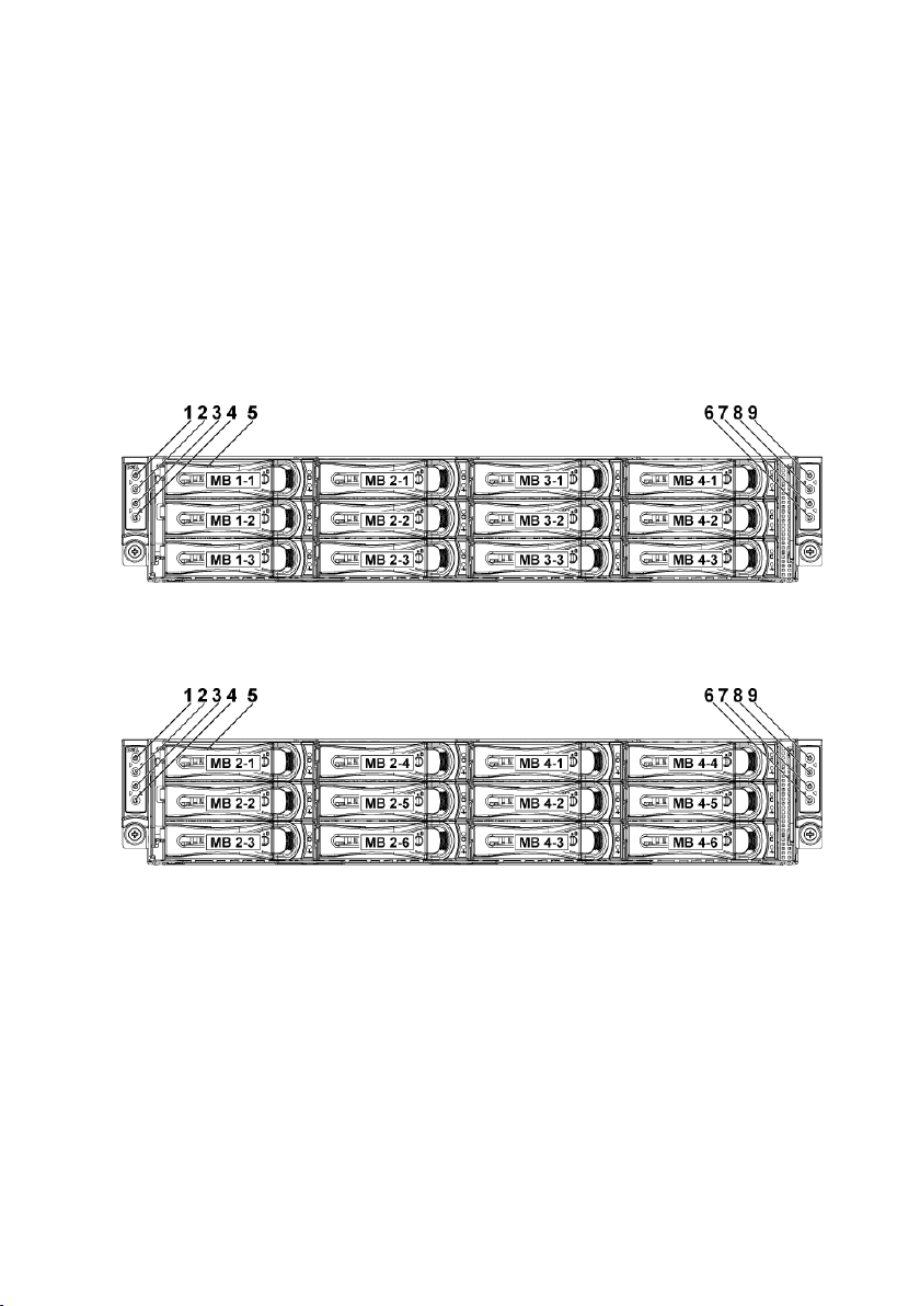
Front-Panel Features and Indicators
Figure 1-1. Front Panel−3.5” x12 Hard Drives With Four System Boards
(C6220/C6220 II RAID Card & Onboard SATA Controller)
Figure 1-2. Front Panel−3.5” x12 Hard Drives With Two System Boards
(C6220/C6220 II RAID Card & C6220 II Onboard SATA Controller)
This system is designed with two types of system boards: C6220 II and
C6220. The system supports the following configurations:
14 | About Your System
Page 15
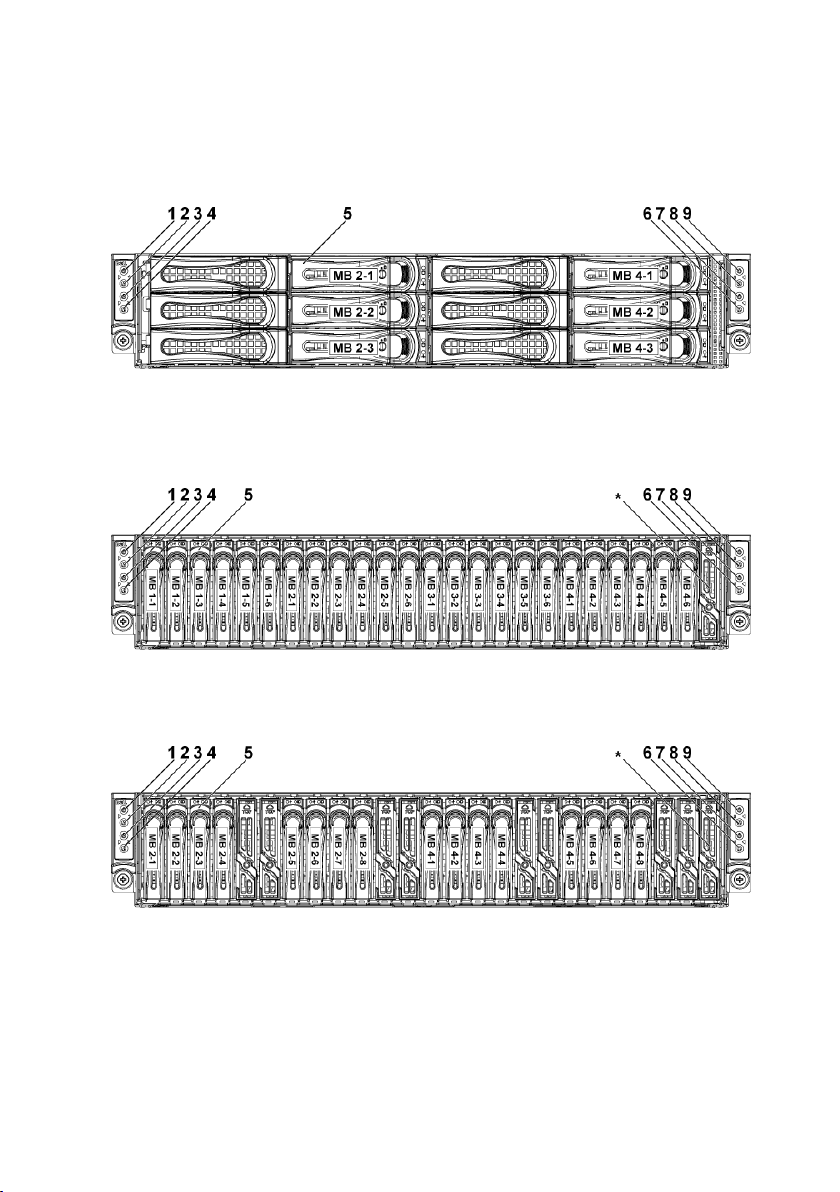
Figure 1-3. Front Panel−3.5” x6 Hard Drives With Two System Board
(C6220 Onboard SATA Controller)
Figure 1-4. Front Panel−2.5” x24 Hard Drives With Four System Boards
(C6220/C6220 II RAID Card & Onboard SATA Controller)
Figure 1-5. Front Panel−2.5” x16 Hard Drives With Two System Boards
(C6220/C6220 II RAID Card)
About Your System | 15
Page 16
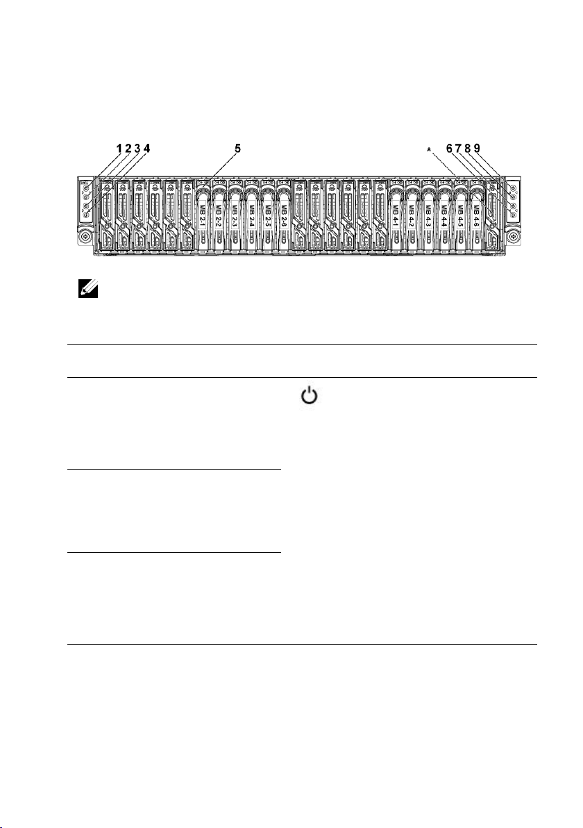
Figure 1-6. Front Panel−2.5” x12 Hard Drives With two System Board
(C6220/C6220 II Onboard SATA Controller)
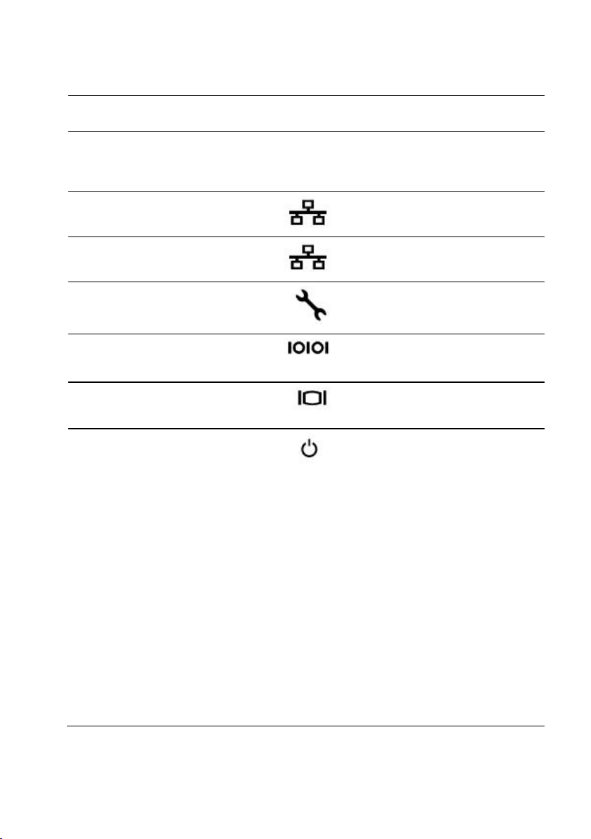
Item
Indicator, Button
Or Connector
Icon
Description
1
Power-on indicator/
system state indicator/
power button for system
board 1
The power-on indicator turns to
green when the system power is
on.
The power-on indicator turns to
amber when the system critical
event occurs.
The power button controls the
DC power supply output to the
system.
NOTE: When powering on the
system, the video monitor can take
from several seconds to over 2
minutes to display an image,
depending on the amount of DIMM
installed in the system.
3
Power-on indicator/
system state indicator/
power button for system
board 2
7
Power-on indicator/
system state indicator/
power button for system
board 4
NOTE: For more information on the direction details of the 2.5-inch hard drive
expander configuration support, see the HDD Zoning configuration tool at
dell.com/support.
16 | About Your System
Page 17

Item
Indicator, Button
Or Connector
Icon
Description
9
Power-on indicator/
system state indicator/
power button for system
board 3
NOTE: On ACPI-compliant
operating systems, turning off the
system using the power button
causes the system to perform a
graceful shutdown before power to
the system is turned off.
NOTE: To force an ungraceful
shutdown, press and hold the
power button for 5 seconds.
2
System identification
indicator/button for
system board 1
The identification button can be
used to locate a particular system
and system board within a chassis.
When the button is pushed, the
system’s blue status indicator on
the front and back blink until the
button is pushed again.
4
System identification
indicator/button for
system board 2
6
System identification
indicator/button for
system board 4
8
System identification
indicator/button for
system board 3
5
Hard Drives
Up to twelve hot-swappable 3.5inch hard drives.
Up to twenty four hot-swappable
2.5-inch hard drives.
*
Drive Cover
Applicable only for 2.5-inch hard
drive system. This is not a usable
drive slot.
About Your System | 17
Page 18
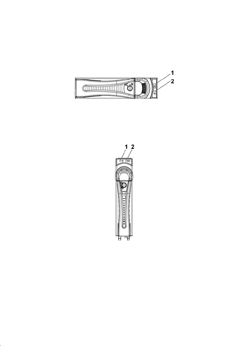
Hard-Drive Indicator Patterns
Figure 1-7. 3.5-inch Hard Drive Indicators
1
hard-drive activity indicator
(green)
2
hard-drive status indicator (green
and amber)
Figure 1-8. 2.5-inch Hard Drive Indicators
1
hard-drive status indicator (green
and amber)
2
hard-drive activity indicator
(green)
18 | About Your System
Page 19

Table 1-1. Hard-Drive Status Indicators−For 3.5"/2.5” Direct Hard-Drive Backplane
Controller
Hard
Drive Type
Function
Activity LED
Status LED
Green
Green
Amber
Onboard
Controller
SATA2
Drive on-line
Off/
Blinking
when active
On
Off
Fail
Off
On
Off
LSI 9265
/LSI 2008
/LSI 9210
SAS
/SATA2
Slot Empty
Off
Off
Off
Drive Online/Access
Blinking
when active
On
Off
Drive Fail
Off Off
On 150 ms
Off 150 ms
Drive Rebuild
Blinking
when active
On 400 ms
Off 100 ms
Off
Drive Identify
Blinking
when active
On 250 ms
Off 250 ms
Off
About Your System | 19
Page 20

Table 1-2. Hard-Drive Status Indicators−For 2.5” Hard-Drive Backplane for
Expander Configuration
Controller
Hard
Drive
Type
Function
Activity LED
Status LED
Green
Green
Amber
LSI 9265
/LSI 2008
/LSI 9210
SAS
/SATA2
Slot Empty
Off
Off
Off
Drive On-line
Blinking
when active
On
Off
Drive Identify /
Preparing for
Removal
Blinking
when active
On
250 ms
Off
250 ms
Off
Drive Rebuild
Blinking
when active
On
400 ms
Off
100 ms
Off
Drive Failed
Off
Off
On
150 ms
Off
150 ms
Predicted
Failure (SMART)
Blinking
when active
On
500 ms
Off
500 ms
Off
1000 ms
Off
500 ms
On
500 ms
Off
1000 ms
Rebuild Abort
Off
On
3000 ms
Off
9000 ms
Off
6000 ms
On
3000 ms
Off
000 ms
20 | About Your System
Page 21
Service Tag
The Service Tag locations for 1U node, 2U node, and the chassis are as
follows:
Figure 1-9 Service Tag Location for 1U Node
Figure 1-10 Service Tag Location for 2U Node
About Your System | 21
Page 22
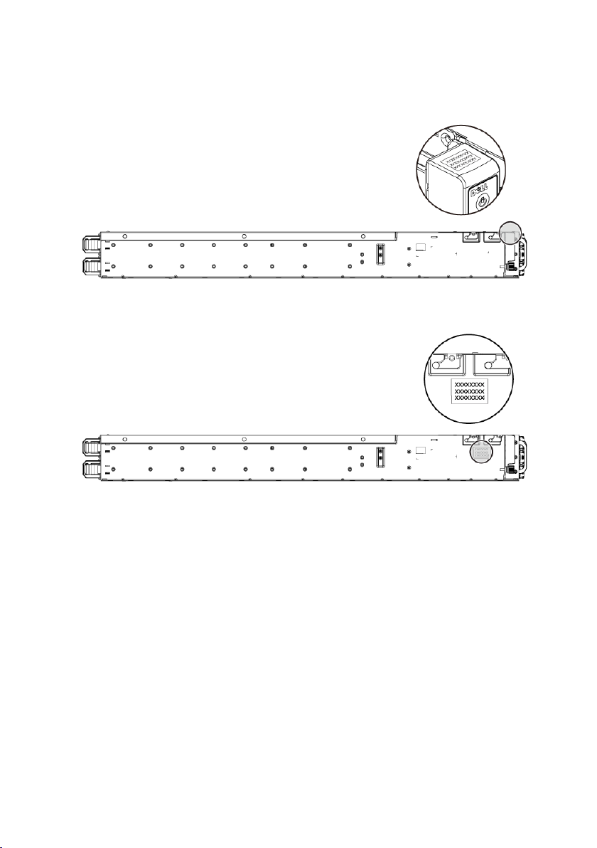
Figure 1-11 Service Tag Location on the Left Front Panel
Figure 1-12 Service Tag Location on the Chassis
22 | About Your System
Page 23
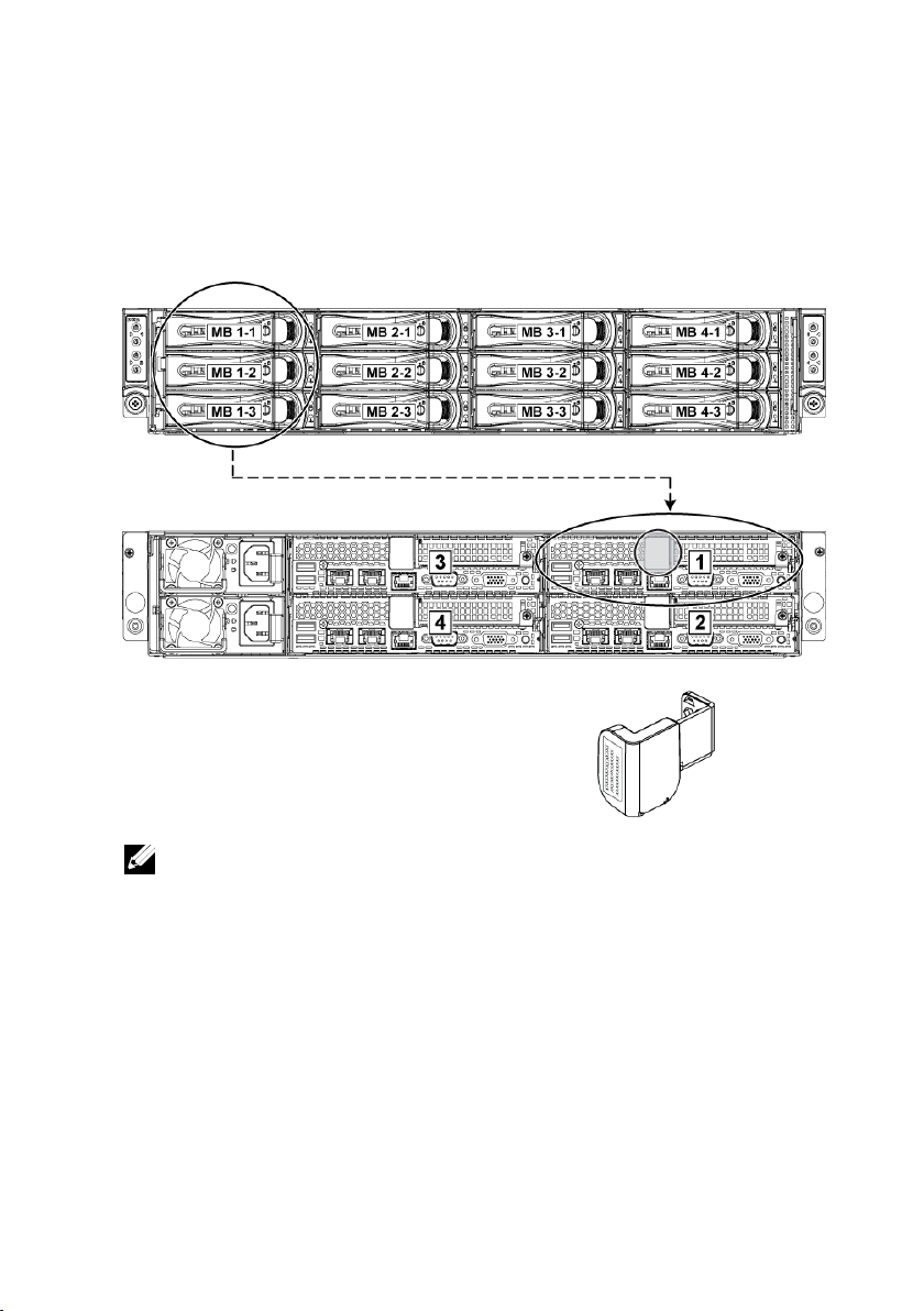
The linkage of 12 hard drives for four system boards is presented as below.
Figure 1-13 Service Tag Linkage
NOTE: HDD’s under warranty would be linked to the appropriate service tag of the
node.
Refer to Front-Panel Features and Indicators on page 14 for other
configurations.
About Your System | 23
Page 24
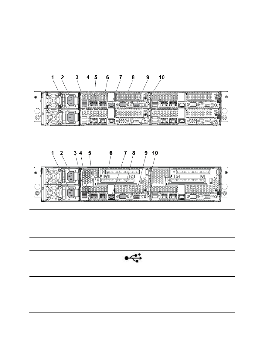
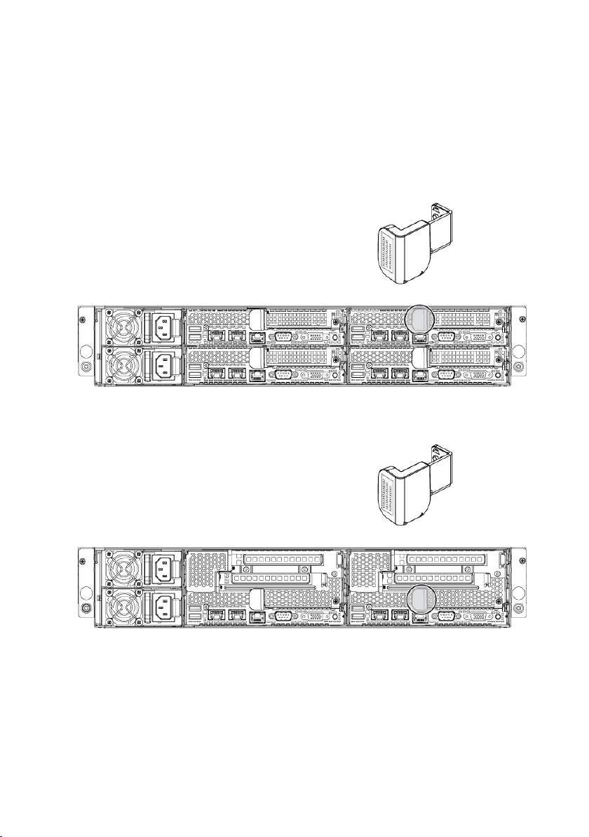
Back Panel Features and Indicators
Item
Indicator, Button
Or Connector
Icon
Description
1
Power supply 2
1200 W/1400 W
2
Power supply 1
1200 W/1400 W
3
dual USB port
Connect USB devices to the
system. The ports are USB 2.0compliant.
4
System identification
indicator
Both the systems management
software and the identification
buttons located on the front can
cause the indicator to flash blue
to identify a particular system
Figure 1-14 Back Panel with Four System Boards
Figure 1-15 Back Panel with Two System Boards
24 | About Your System
Page 25
Item
Indicator, Button
Or Connector
Icon
Description
and system board. Lights amber
when the system needs attention
due to a problem.
5
LAN connector 1
Embedded 10/100/1000 NIC
connectors.
6
LAN connector 2
Embedded 10/100/1000 NIC
connectors.
7
Management port
Dedicated management port.
8
Serial port
Connects a serial device to the
system.
9
VGA port
Connects a VGA display to the
system.
10
Power-on indicator/
system state indicator/
power button
The power-on indicator turns to
green when the system power is
on.
The power-on indicator turns to
amber when the system critical
event occurs.
The power button controls the
DC power supply output to the
system.
NOTE: When powering on the
system, the video monitor can take
from several seconds to over 2
minutes to display an image,
depending on the amount of
memory installed in the system.
NOTE: On ACPI-compliant
operating systems, turning off the
About Your System | 25
Page 26
Item
Indicator, Button
Or Connector
Icon
Description
system using the power button
causes the system to perform a
graceful shutdown before power to
the system is turned off.
NOTE: To force an ungraceful
shutdown, press and hold the
power button for five seconds.
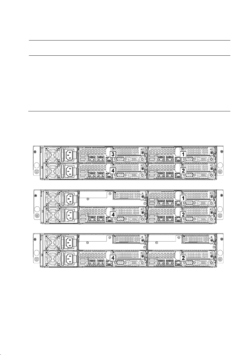
System-Board Assembly Configurations
Figure 1-16. Enumeration Four System Boards for 1U Node
Figure 1-17. Enumeration Three System Boards for 1U Node
Figure 1-18. Enumeration Two System Boards for 1U Node
26 | About Your System
Page 27
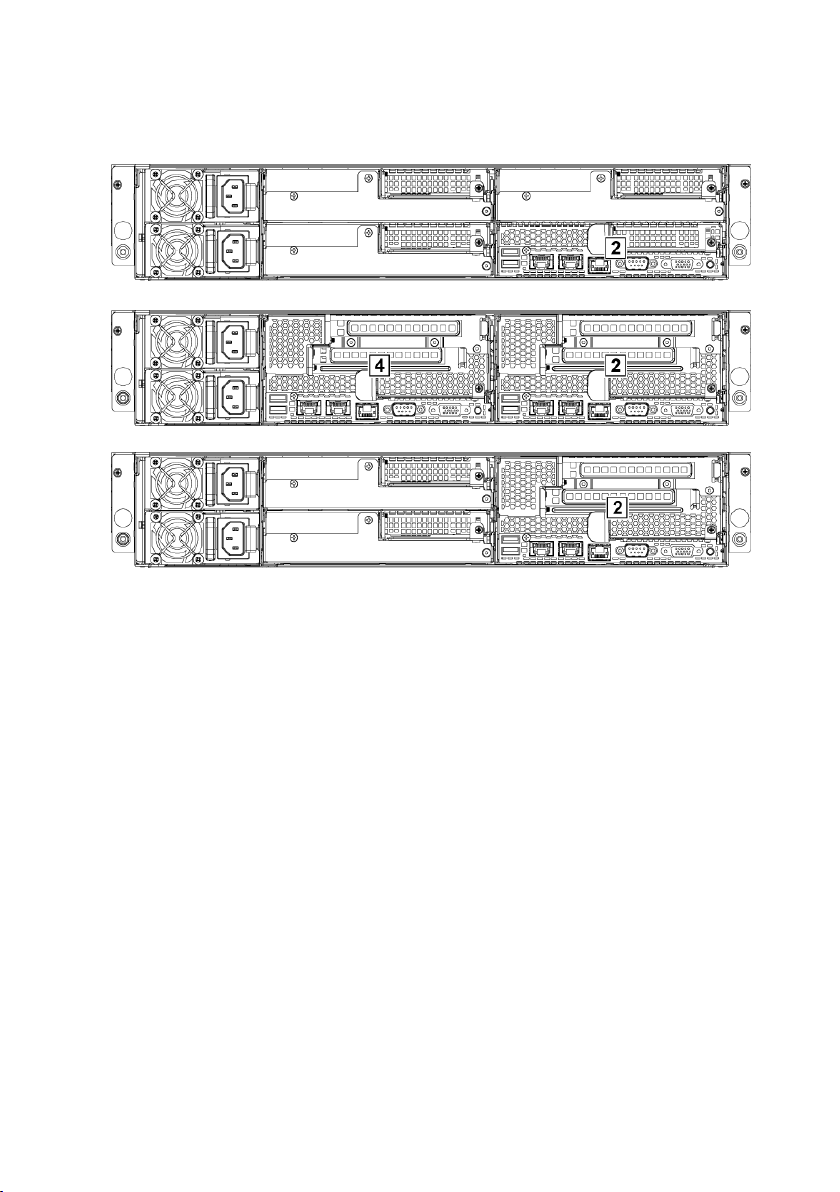
Figure 1-19. Enumeration One System Board for 1U Node
Figure 1-20. Enumeration Two System Boards for 2U Node
Figure 1-21. Enumeration One System Board for 2U Node
About Your System | 27
Page 28
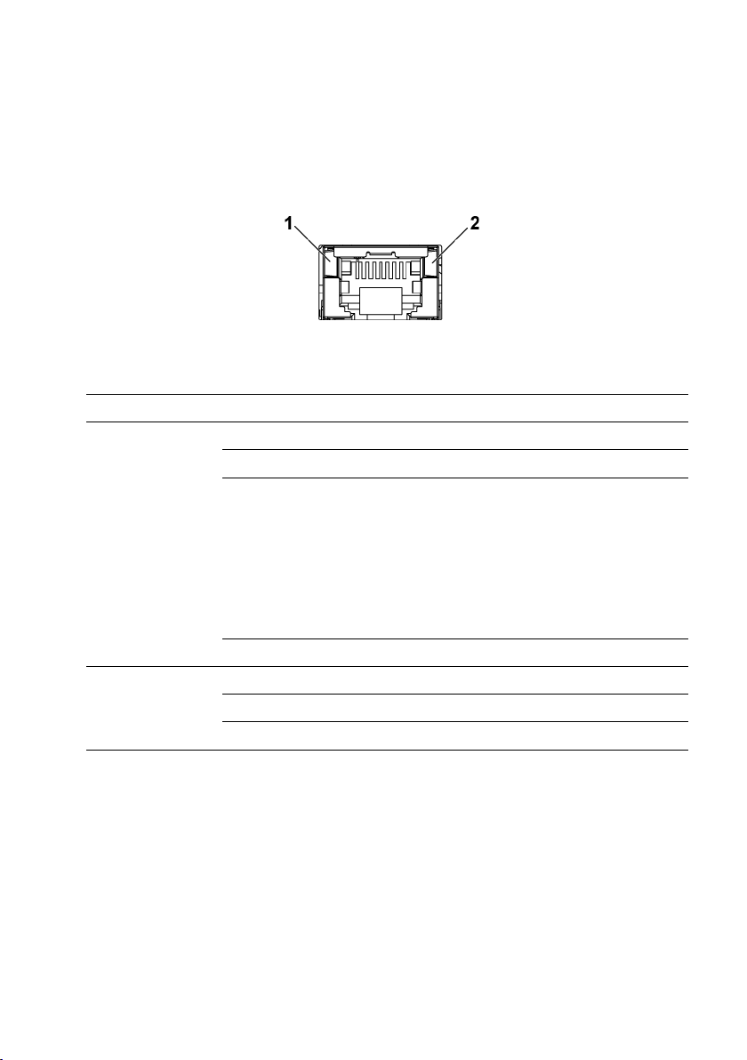
LAN Indicator Codes
Figure 1-22. LAN Indicators
1
speed indicator
2
link/activity indicator
Component
Indicator
Condition
Speed
indicator
Solid amber
Linking at 100Mbps speed
Solid green
Linking at 1Gbps speed (maximum)
Blinking green
Linking at 1Gbps speed.
Activity is present:
- Pre OS POST
- OS without driver
- OS with driver
Blinking at speed relative to packet
density.
Off
Linking at 10Mbps speed
Link/activity
indicator
Solid green
No access
Blinking green
LAN accessing / Link up
Off
Idle
28 | About Your System
Page 29

Figure 1-23. LAN Indicators (Management Port)
1
speed indicator
2
link/activity indicator
Component
Indicator
Condition
Speed indicator
Blinking green
Linking at 100Mbps speed (maximum)
Blinking amber
Linking at 10Mbps speed
Link/activity
indicator
Solid green
No access
Blinking green
LAN accessing / Link up
Off
Idle
About Your System | 29
Page 30

Power and System Board Indicator Codes
Table 1-3. Status Indicator Codes
Component
Indicator
Condition
Power-on
indicator
(A bi-color LED
on power button)
Green
Solid
Power On (S0)
Amber
Off
Green
Off
BMC critical condition event in Power
Off mode (S4/S5)
Amber
Blinking
Green
Off
BMC critical condition event in Power
On mode (S0)
Amber
Blinking
System
identification
indicator
Steady Blue
IPMI via Chassis Identify Command On
or ID Button Press ID On
Blinking Blue
Only IPMI via Chassis Identify
Command Blink On
Off
IPMI via Chassis Identify Command Off
or ID Button Press ID Off
The LEDs on the system front panel and back panel display status codes
during system startup. For location of the LEDs on the front panel, see
Figure 1-1 for 3.5” hard drive and Figure 1-4 for 2.5” hard drive systems. For
location of the LEDs on the back panel, see Figure 1-14 and Figure 1-15.
Table 1-3 lists the status associated with the status codes.
30 | About Your System
Page 31

Power Supply Indicator Codes
Figure 1-24. Power Supply Status Indicator
1
power supply
2
AC power indicator
Component
Indicator
Condition
AC power
indicator
Solid green
System is on.
Blinking green
System is off.
Off
AC off.
1400W Power Supply
About Your System | 31
Page 32

1200W Power Supply
Figure 1-25. Power Supply Status Indicator
1
power supply
2
AC power Indicator
Component
Indicator
Condition
AC power
indicator
Solid green
AC on.
Yellow
Fault.
Off
AC off.
32 | About Your System
Page 33

BMC Heart Beat LED
Figure 1-26. BMC Heart Beat LED on the System Board C6220 II
Figure 1-27. BMC Heart Beat LED on the C6220 System Board
1
BMC heart beat LED
2
system board
The system board provides BMC heart beat LED (LED17) for BMC debugs.
The BMC heart beat LED is green. When the system AC power is
connected, the LED lights. When BMC firmware is ready, the BMC heart
beat LED blinks.
About Your System | 33
Page 34

Post Error Code
Error Code
Error Message
Error Cause
Recovery Method
0010h
Local Console Resource
Conflict
Video device
initialization failed
Make sure video
device is well
0011h
Local Console Controller
Error
Video device
initialization failed
Make sure video
device is well
Collecting System Event Log (SEL) for Investigation
Whenever possible, the BIOS will output the current boot progress codes on
the video screen. Progress codes are 32-bit quantities plus optional data. The
32-bit numbers include class, subclass, and operation information. The class
and subclass fields point to the type of hardware that is being initialized.
The operation field represents the specific initialization activity. Based on
the data bit availability to display progress codes, a progress code can be
customized to fit the data width. The higher the data bit, the higher the
granularity of information that can be sent on the progress port. The
progress codes may be reported by the system BIOS or option ROMs.
The Response section in the following table is divided into 3 types:
1 Warning or Not an error – The message is displayed on the screen. An
error record is logged to the SEL. The system will continue booting with
a degraded state. The user may want to replace the erroneous unit.
2 Pause – The message is displayed on the screen, an error is logged to the
SEL, and user input is required to continue or not depending on SETUP
option. The user can take immediate corrective action or choose to
continue booting.
3 Halt – The message is displayed on the screen, an error is logged to the
SEL, and the system cannot boot unless the error is resolved. The user
needs to replace the faulty part and restart the system.
34 | About Your System
Page 35

Error Code
Error Message
Error Cause
Recovery Method
0012h
Local Console Output Error
Video device
initialization failed
Make sure video
device is well
0013h
ISA IO Controller Error
ISA device's IO
initialization failed
Make sure ISA
device is well
0014h
ISA IO Resource Conflict
ISA device's IO
initialization failed
Make sure ISA
device is well
0015h
ISA IO Controller Error
ISA device's IO
initialization failed
Make sure ISA
device is well
0016h
ISA Floppy Controller Error
Floppy
initialization failed
Make sure floppy
device is well
0017h
ISA Floppy Input Error
Floppy
initialization failed
Make sure floppy
device is well
0018h
ISA Floppy Output Error
Floppy
initialization failed
Make sure floppy
device is well
0019h
USB Read Error
USB initialization
failed
Check USB port is
well
001Ah
USB Write Error
USB initialization
failed
Check USB port is
well
001Bh
USB Interface Error
USB port
initialization failed
Check USB port is
well
001Ch
Mouse Interface Error
Mouse device
initialization failed
Make sure mouse
device is well
001Eh
Keyboard not Detected
No keyboard be
detected
Install keyboard
001Fh
Keyboard Controller Error
KBC initialization
failed
Make sure KBC is
well
0020h
Keyboard Stuck Key Error
Keyboard Stuck
Key Error
Make sure PS2 KB
device is well
0021h
Keyboard Locked Error
Keyboard Locked
Make sure PS2
About Your System | 35
Page 36

Error Code
Error Message
Error Cause
Recovery Method
Error
KB device is well
0023h
Memory Correctable Error
Memory
correctable error be
detected
Reset power or
change new
memory
0024h
Memory Uncorrectable
Error
Memory
uncorrectable error
be detected
Reset power or
change new
memory
0025h
Memory Non-Specific Error
Memory nonspecific error
Change new
memory
0026h
MP Service Self Test Error
MP service self test
error
Change processor
0027h
PCI IO Controller Error
PCI device
initialization failed
Make sure PCI
device is well
0028h
PCI IO Read Error
PCI device
initialization failed
Make sure PCI
device is well
0029h
PCI IO Write Error
PCI device
initialization failed
Make sure PCI
device is well
002Ah
Serial Port not Detected
Serial controller
initialization failed
Make sure serial
controller is well
002Bh
Serial Port Controller Error
Serial controller
initialization failed
Make sure serial
controller is well
002Ch
Serial Port Input Error
Serial controller
initialization failed
Make sure serial
controller is well
002Dh
Serial Port Output Error
Serial controller
initialization failed
Make sure serial
controller is well
002Eh
Microcode Update Error
Processor
microcode load
failed
Check microcode
36 | About Your System
Page 37

Error Code
Error Message
Error Cause
Recovery Method
002Fh
No Microcode be Updated
Processor
microcode load
failed
Check processor
stepping and
microcode are
match
8018h
Sparing Mode is not be
Configured!! Please check
Memory Configuration!!
Memory sparing
mode failed
Change memory
configuration for
sparing mode
8019h
Mirror Mode is not be
Configured!! Please check
Memory Configuration!!
Memory mirror
mode failed
Change memory
configuration for
mirror mode
8021h
CMOS Battery Fault!!
No CMOS battery
Install CMOS
battery
8100h
Memory Device disable by
BIOS.
Memory Device
Error.
Change memory
device
About Your System | 37
Page 38

System Event Log
Message: “Processor Sensor, IERR error, Processor 1”
Byte
Field
Value
Description
1
NetFunLun
10h 2
Platform Event Command
02h
3
Generator ID
01h
Generated by BIOS
4
Event Message Format Version
04h
Event Message Format
Revision. 04h for this
specification
5
Sensor Type
07h
Processor
6
Sensor Number
04h
Processor Sensor Number
(depends on platform)
7
Event Direction Event Type
6Fh
Bit 7: 0 = Assert Event
Bit 6: 0 = Event Type Code
8
Event Data1
AXh
00h: IERR
01h: Thermal Trip
02h: FRB1/BIST Failure
03h: FRB2/Hang in POST
Failure
04h: FBR3/Processer
Startup/Initialization Failure
0Ah: Processor Automatically
Throttled
9
Event Data2
XXh
00h: Processor1
01h: Processor2
02h: Processor3
04h: Processor4
10
Event Data3
FFh
FFh: Not Present
Processor Error
38 | About Your System
Page 39

Memory ECC
Byte
Field
Value
Description
1
NetFunLun
10h
2
Platform Event Command
02h 3
Generator ID
01h
Generated by BIOS
4
Event Message
Format Version
04h
Event Message Format
Revision. 04h for this
specification (IPMI 2.0)
5
Sensor Type
0Ch
Memory
6
Sensor Number
60h
Memory Sensor Number
(depend on platform)
7
Event Direction
Event Type
6Fh
Bit 7: 0 = Assert Event
Bit 6: 0 = Event Type Code
8
Event Data1
AXh
00h: Correctable ECC Error
01h: Uncorrectable ECC Error
03h: Memory Scrub Failed
04h: Memory Device Disabled
08h: Spare
9
Event Data2
XXh
Bit 7:4
0x00: SBE warning threshold
0x01: SBE critical threshold
0x0F: Unspecified
Bit 3:0
0x00: CPU1 DIMM A1-8
slots (1~8)
0x01: CPU2 DIMM B1-8
slots (9~16)
0x02: CPU3 DIMM C1-8
slots (17~24)
0x03: CPU4 DIMM D1-8
slots (25~32) And so on…
Message: “Memory Sensor, Correctable ECC error, SBE warning threshold,
CPU1 DIMM_A1”
About Your System | 39
Page 40

Byte
Field
Value
Description
10
Event Data3
XXh
DIMM bit-map locatation of
bits
Bit 0=1: DIMM1 error event
Bit 1=1: DIMM2 error event
…
Bit7=1: DIMM8 error event
PCI-E Error
Byte
Field
Value
Description
1
NetFunLun
10h 2
Platform Event Command
02h 3
Generator ID
01h
Generated by BIOS
4
Event Message
Format Version
04h
Event Message Format
Revision. 04h for this
specification.
5
Sensor Type
13h
Critical Interrupt
6
Sensor Number
73h
PCI Sensor ID (depend on
platform)
7
Event Direction
Event Type
6Fh
Bit 7: 0 = Assert Event
Bit 6: 0 = Event Type Code
8
Event Data1
AXh
04h: PCI PERR
05h: PCI SERR
07h: Bus Correctable Error
08h: Bus Uncorrectable Error
0Ah: Bus Fatal Error
9
Event Data2
XXh
Bit 7:3Device Number
Bit 2:0Function Number
10
Event Data3
XXh
Bit 7:0 Bus Number
Message: “Critical Interrupt Sensor, PCI PERR, Device#, Function#, Bus#
“
40 | About Your System
Page 41

IOH Core Error
Message: “Critical Interrupt Sensor, Fatal Error, xxxx bit, QPI[0] Error”
Byte
Field
Value
Description
1
NetFunLun
10h 2
Platform Event Command
02h 3
Generator ID
01h
Generated by BIOS
4
Event Message
Format Version
04h
Event Message Format
Revision. 04h for this
specification.
5
Sensor Type
C0h
OEM Defined Interrupt
6
Sensor Number
XXh
71h: QPI Sensor ID (depend
on platform)
72h: INT Sensor ID (depend
on platform)
7
Event Direction
Event Type
6Fh
Bit 7: 0 = Assert Event
Bit 6: 0 = Event Type Code
8
Event Data1
AXh
07h: Core
08h: Non-Fatal
0Ah: Fatal
9
Event Data2
XXh
Local Error Bit
10
Event Data3
XXh
00h: QPI[0] Error
01h: QPI[1] Error
02h: QPI[2] Error
03h: QPI[3] Error
04h: QPI[0] Protocol Error
05h: QPI[1] Protocol Error
06h: QPI[2] Protocol Error
07h: QPI[3] Protocol Error
23h: Miscellaneous Error
24h: IOH Core Error
About Your System | 41
Page 42

SB Error
Message: “Critical Interrupt Sensor, Correctable, MCU Parity Error”
Byte
Field
Value
Description
1
NetFunLun
10h 2
Platform Event Command
02h 3
Generator ID
01h
Generated by BIOS
4
Event Message
Format Version
04h
Event Message Format
Revision. 04h for this
specification.
5
Sensor Type
13h
Critical Interrupt
6
Sensor Number
77h
SB Sensor ID (depend on
platform)
7
Event Direction
Event Type
6Fh
Bit 7: 0 = Assert Event
Bit 6: 0 = Event Type Code
8
Event Data1
AXh
07h: Correctable
08h: Uncorrectable
9
Event Data2
XXh
Bit 7:5Reserved
Local error bit number (4 ~ 0)
00000b: HT Periodic CRC
Error
00001b: HT Protocol Error
00010b: HT Flow-Control
Buffer Overflow
00011b: HT Response Error
00100b: HT Per-Packet CRC
Error
00101b: HT Retry Counter
Error
00111b: MCU Parity Error
10
Event Data3
FFh
FFh: Not Present
42 | About Your System
Page 43

POST Start Event
Message: “System Event, POST starts with BIOS xx.xx.xx”
Byte
Field
Value
Description
1
NetFunLun
10h 2
Platform Event Command
02h 3
Generator ID
01h
Generated by BIOS
4
Event Message
Format Version
04h
Event Message Format
Revision. 04h for this
specification.
5
Sensor Type
12h
System Event
6
Sensor Number
81h
POST Start (depend on
platform)
7
Event Direction
Event Type
6Fh
Bit 7: 0 = Assert Event
Bit 6: 0 = Event Type Code
8
Event Data1
AXh
01h: OEM System Boot Event
9
Event Data2
XXh
7~4: BIOS 1st Field Version
(0~15)
3~0: BIOS 2nd Field Version
higher 4bits (0~63)
10
Event Data3
XXh
7~6: BIOS 2nd Field Version
lower 2bits (0~63)
5~0: BIOS 3rd Field Version
(0~63)
About Your System | 43
Page 44

POST End Event
Byte
Field
Value
Description
1
NetFunLun
10h
2
Platform Event Command
02h
3
Generator ID
01h
Generated by BIOS
4
Event Message
Format Version
04h
Event Message Format
Revision. 04h for this
specification.
5
Sensor Type
12h
System Event
6
Sensor Number
85h
POST End (depend on
platform)
7
Event Direction
Event Type
6Fh
Bit 7: 0 = Assert Event
Bit 6: 0 = Event Type Code
8
Event Data1
AXh
01h: OEM System Boot Event
9
Event Data2
XXh
Bit 7 = Boot Type
0b: PC Compatible Boot
(Legacy)
1b: uEFI Boot
Bit 3:0 = Boot Device
0001b: Force PXE Boot
0010b: NIC PXE Boot
0011b: Hard Disk Boot
0100b: RAID HDD Boot
0101b: USB Storage Boot
0111b: CD/DVD ROM Boot
1000b: iSCSI Boot
1001b: uEFI Shell
1010b: ePSA Diagnostic
Boot
10
Event Data3
FFh
FFh: Not Present
44 | About Your System
Page 45

POST Error Code Event
Byte
Field
Value
Description
1
NetFunLun
10h 2
Platform Event Command
02h 3
Generator ID
01h
Generated by BIOS
4
Event Message
Format Version
04h
Event Message Format
Revision. 04h for this
specification.
5
Sensor Type
0Fh
System Firmware Progress
6
Sensor Number
86h
POST Error (depend on
platform)
7
Event Direction
Event Type
6Fh
Bit 7: 0 = Assert Event
Bit 6: 0 = Event Type Code
8
Event Data1
AXh
00: System Firmware Error
(POST Error)
9
Event Data2
XXh
Upper Byte
10
Event Data3
XXh
Lower Byte
Byte
Field
Value
Description
1
NetFunLun
10h 2
Platform Event Command
02h
3
Generator ID
01h
Generated by BIOS
4
Event Message
Format Version
04h
Event Message Format
Revision. 04h for this
specification.
5
Sensor Type
12h
System Event
6
Sensor Number
89h
BIOS Recovery fail (depend
on platform)
7
Event Direction
Event Type
6Fh
Bit 7: 0 = Assert Event
Bit 6: 0 = Event Type Code
Message: “System Firmware Progress, POST error code: UBLBh.”
BIOS Recovery Event
About Your System | 45
Page 46

Byte
Field
Value
Description
8
Event Data1
AXh
01h: OEM BIOS recovery
Event
9
Event Data2
XXh
01h:Start Recovery
02h:Recovery Success
03h:Load Image Fail
04h:Signed Fail
10
Event Data3
FFh
FFh: Not Present
ME Fail Event
Byte
Field
Value
Description
1
NetFunLun
10h 2
Platform Event Command
02h
3
Generator ID
01h
Generated by BIOS
4
Event Message
Format Version
04h
Event Message Format
Revision. 04h for this
specification.
5
Sensor Type
12h
System Event
6
Sensor Number
8Ah
ME fail (depend on platform)
7
Event Direction
Event Type
6Fh
Bit 7: 0 = Assert Event
Bit 6: 0 = Event Type Code
8
Event Data1
AXh
01h: OEM ME fail Event
9
Event Data2
XXh
01h:ME fail
10
Event Data3
FFh
FFh: Not Present
Generator ID
BIOS
0x0001
BMC
0x0020
ME
0x002C
Windows 2008
0x0137
SEL Generator ID
46 | About Your System
Page 47

Sensor Data Record
Record
ID
Sensor
Numbe
Sensor
Name
Sensor
Type
Event/Reading
Type
Offset
0004h
0x01
SEL Fullness
Event Logging
Disabled (10h)
Sensor-specific (6Fh)
SI: 67h SC: 40h AM:
0035h DM: 0000h
RM: 0035h
0001h
0x02
P1
ThermalTrip
Processor (07h)
Sensor-specific (6Fh)
SI: 01h SC: 40h AM:
0002h DM: 0000h
RM: 0002h
0002h
0x03
P2
ThermalTrip
Processor (07h)
Sensor-specific (6Fh)
SI: 01h SC: 40h AM:
0002h DM: 0000h
RM: 0002h
0003h
0x04
CPU ERR2
Processor (07h)
Sensor-specific (6Fh)
SI: 01h SC: 40h AM:
0001h DM: 0000h
RM: 0001h
0005h
0x05
12V Standby
Voltage (02h)
Threshold (01h)
SI: 7Fh SC: 59h AM:
7A95h DM: 7A95h
TM: 3F3Fh
NOTE: The abbreviations used in the following table are:
SI: Sensor Initialization DM: Deassertion Mask
SC: Sensor Capabilities RM: Reading Mask
AM: Assertion Mask TM: Settable/Readable Threshold Mask
Event Log Only: the sensor will be only used to explain event log, and will
show disable about sensor state.
About Your System | 47
Page 48

Record
ID
Sensor
Numbe
Sensor
Name
Sensor
Type
Event/Reading
Type
Offset
0007h
0x06
5V
Voltage (02h)
Threshold (01h)
SI: 7Fh SC: 59h AM:
7A95h DM: 7A95h
TM: 3F3Fh
0006h
0x07
5V Standby
Voltage (02h)
Threshold (01h)
SI: 7Fh SC: 59h AM:
7A95h DM: 7A95h
TM: 3F3Fh
0009h
0x08
3.3V
Voltage (02h)
Threshold (01h)
SI: 7Fh SC: 59h AM:
7A95h DM: 7A95h
TM: 3F3Fh
0008h
0x09
3.3V
Standby
Voltage (02h)
Threshold (01h)
SI: 7Fh SC: 59h AM:
7A95h DM: 7A95h
TM: 3F3Fh
001Ah
0x0A
Battery low
Battery (29h)
Sensor-specific (6Fh)
SI: 67h SC: 40h AM:
0001h DM: 0000h
TM: 0001h
000Bh
0x40
MEZZ1
TEMP
Temperature
(01h)
Threshold (01h)
SI: 7Fh SC: 68h AM:
0A95h DM: 7A95h
TM: 3838h
000Ch
0x41
CPU1 Temp
Temperature
(01h)
Threshold (01h)
SI: 7Fh SC: 68h AM:
0A95h DM: 7A95h
TM: 3838h
48 | About Your System
Page 49

Record
ID
Sensor
Numbe
Sensor
Name
Sensor
Type
Event/Reading
Type
Offset
000Dh
0x42
CPU2 Temp
Temperature
(01h)
Threshold (01h)
SI: 7Fh SC: 68h AM:
0A95h DM: 7A95h
TM: 3838h
000Eh
0x43
DIMM
ZONE 1
Temp
Temperature
(01h)
Threshold (01h)
SI: 7Fh SC: 68h AM:
0A95h DM: 7A95h
TM: 3838h
000Fh
0x44
DIMM
ZONE 2
Temp
Temperature
(01h)
Threshold (01h)
SI: 7Fh SC: 68h AM:
0A95h DM: 7A95h
TM: 3838h
0012h
0x45
PCH Temp
Temperature
(01h)
Threshold (01h)
SI: 7Fh SC: 68h AM:
0A95h DM: 7A95h
TM: 3838h
0017h
0x60
Memory
Memory (0Ch)
Sensor-specific (6Fh)
SI: 01h SC: 40h AM:
0023h DM: 0000h
RM: 0023h
0013h
0xA0
Watchdog
Watchdog 2
(23h)
Sensor-specific (6Fh)
SI: 67h SC: 40h AM:
000Fh DM: 0000h
RM: 000Fh
0016h
0xA2
AC lost
(Event Log
Only)
Power Unit
(09h)
Sensor-specific (6Fh)
SI: 01h SC: 40h
AM: 0010h DM: 0000h
RM: 0010h
About Your System | 49
Page 50

Record
ID
Sensor
Numbe
Sensor
Name
Sensor
Type
Event/Reading
Type
Offset
N/A
0x2F
Session
Audit
(Event Log
Only)
Session Audit
(2Ah)
N/A
N/A
0019h
0xA3
Sys Pwr
Monitor
System ACPI
Power State
(22h)
Sensor-specific (6Fh)
SI: 01h SC: 40h
AM: 0021h DM: 0000h
RM: 0021h
Dynamic
0xB6
PSU1 Status
Power Supply
(08h)
Sensor-specific (74h)
SI: 67h SC: 40h
AM: 000Bh DM: 000Bh
RM: 000Bh
Dynamic
0xB7
PSU2 Status
Power Supply
(08h)
Sensor-specific (74h)
SI: 67h SC: 40h
AM: 000Bh DM: 000Bh
RM: 000Bh
Dynamic
0xB8
PSU3 Status
Power Supply
(08h)
Sensor-specific (74h)
SI: 67h SC: 40h
AM: 000Bh DM: 000Bh
RM: 000Bh
Dynamic
0xB9
PSU4 Status
Power Supply
(08h)
Sensor-specific (74h)
SI: 67h SC: 40h
AM: 000Bh DM: 000Bh
RM: 000Bh
Dynamic
0xE1
PSU
Mismatch
Power Supply
(08h)
Sensor-specific
(0x6F)
SI: 67h SC: 40h AM:
0040h DM: 0040h
RM: 0040h
Dynamic
0xE2
PSU
Redundancy
Power Supply
(08h)
Discrete(0x0Bh)
SI: 67h SC: 00h AM:
002Fh DM: 000Bh
RM: 002Fh
50 | About Your System
Page 51

Record
ID
Sensor
Numbe
Sensor
Name
Sensor
Type
Event/Reading
Type
Offset
Dynamic
0x64
12V
Voltage(02h)
Threshold(01h)
Variable
Dynamic
0xB1
Inlet Temp
Temperature
(01h)
Threshold(01h)
Variable
Dynamic
0xB3
Input
Voltage
Voltage(02h)
Threshold(01h)
Variable
Dynamic
0xB4
Input
Current
Current(03h)
Threshold(01h)
Variable
Dynamic
0xB5
SC FW
Status
Management
Subsystem
Health(28h)
Sensor-specific
(0x6F)
Variable
Dynamic
0xC7
HDD 1
Status
Drive Slot
(Bay)(0Dh)
Sensor-specific
(0x6F)
Variable
Dynamic
0xC8
HDD 2
Status
Drive Slot
(Bay)(0Dh)
Sensor-specific
(0x6F)
Variable
Dynamic
0xC9
HDD 3
Status
Drive Slot
(Bay)(0Dh)
Sensor-specific
(0x6F)
Variable
Dynamic
0xCA
HDD 4
Status
Drive Slot
(Bay)(0Dh)
Sensor-specific
(0x6F)
Variable
Dynamic
0xCB
HDD 5
Status
Drive Slot
(Bay)(0Dh)
Sensor-specific
(0x6F)
Variable
Dynamic
0xCC
HDD 6
Status
Drive Slot
(Bay)(0Dh)
Sensor-specific
(0x6F)
Variable
Dynamic
0xD3
FAN_1
Fan(04h)
Threshold (01h)
Variable
Dynamic
0xD4
FAN_2
Fan(04h)
Threshold (01h)
Variable
Dynamic
0xD5
FAN_3
Fan(04h)
Threshold (01h)
Variable
Dynamic
0xD6
FAN_4
Fan(04h)
Threshold (01h)
Variable
Dynamic
0xD7
FAN_5
Fan(04h)
Threshold (01h)
Variable
Dynamic
0xD8
FAN_6
Fan(04h)
Threshold (01h)
Variable
About Your System | 51
Page 52

Other Information You May Need
WARNING: See the safety and regulatory information that shipped with your
system. Warranty information may be included within this document or as a
separate document.
NOTE: Always check for updates on dell.com/support/home and read the updates
first because they often supersede information in other documents.
Expanded Operating Temperature
10% of annual
operating hours
5 °C to 40 °C, 5% to 85% RH with 26 °C max. dew point.
For temperatures between 35 °C and 40 °C, de-rate maximum
allowable dry bulb temperature by 1 °C/175 meters above 950
meters (1 °F per 319 feet).
1% of annual
operating hours
–5 °C to 45 °C, 5% to 90% RH with 26 °C dew point.
For temperatures between 40 °C and 45 °C, de-rate maximum
allowable dry bulb temperature by 1 °C/125 meters above 950
meters (1 °F per 228 feet).
NOTE: When operating in the expanded temperature range,
ambient temperature warnings may be reported in the System
Event Log.
NOTE: No cold start up below 5 °C.
NOTE: The operating temperature specification is for a
maximum altitude of 3048 meters (10,000 feet).
NOTE:
1U and 2U nodes support the 130W (8 core),
130W (4 core) and 135W processors with the specific
configurations of HDD, PCI-E and Mezzanine card.
Refer to the following statements and matrixes of Fresh
Air Support for details.
The numbers of HDD in the tables below list the total
quantity supported per chassis.
No GPU support.
The
Getting Started Guide
features, setting up your system, and technical specifications.
C6220 Fresh Air Support
provides an overview of rack installation, system
52 | About Your System
Page 53

1U node can’t support PCI-E and Mezzanine card at the
same time.
2U node only can be installed one PCI-E and Mezzanine
card by each MB.
Matrix of Fresh Air Support of 1U node with 3.5” HDD configuration
10 ~ 30 °C
35 °C 40 °C 45 °C
60W
12*HDD
Full
configuration
10*HDD
Full
configuration
4*HDD
Full
configuration
4*HDD
16*DIMM, w/o
PCI-E card,
w/o mezzanine
card
70W
12*HDD
Full
configuration
12*HDD
Full
configuration
8*HDD
Full
configuration
4*HDD
16*DIMM, w/o
PCI-E card
w/ mezzanine
card,
80W
12*HDD
Full
configuration
12*HDD
Full
configuration
10*HDD
Full
configuration
4*HDD
16*DIMM, w/o
PCI-E card,
w/o mezzanine
card
95W
12*HDD
Full
configuration
12*HDD
Full
configuration
8*HDD
Full
configuration
4*HDD
16*DIMM, w/o
PCI-E card,
w/o mezzanine
card
NOTE: The full configuration includes two processors, sixteen DIMMs, one PCI-E
card for 1U node/two PCI-E cards for 2U node, and one mezzanine card.
About Your System | 53
Page 54

115W
12*HDD
Full
configuration
12*HDD
Full
configuration
8*HDD
Full
configuration
4*HDD
16*DIMM,
w/o PCI-E card,
w/o mezzanine
card
130W (8 core)
12*HDD
Full
configuration
10 * HDD
Full
configuration
4*HDD
Full
configuration
4*HDD
16*DIMM,
w/o PCI-E card,
w/o mezzanine
card
130W (4 core)
8*HDD
Full
configuration
4*HDD
16*DIMM,
w/o PCI-E card,
w/o mezzanine
card
not support
not support
135W
4*HDD
Full
configuration
4*HDD,
16*DIMM,
w/o PCI-E card,
w/o mezzanine
card
not support
not support
54 | About Your System
Page 55

Matrix of Fresh Air Support of 1U node with 2.5” HDD configuration
10 ~ 30 °C
35 °C 40 °C 45 °C
60W
24*HDD
Full
configuration
24*HDD
Full
configuration
8*HDD
Full
configuration
4*HDD
16*DIMM,
w/o PCI-E card,
w/o mezzanine
card
70W
24*HDD
Full
configuration
24*HDD
Full
configuration
16*HDD
Full
configuration
4*HDD
16*DIMM,
w/o PCI-E card,
w/o mezzanine
card
80W
24*HDD
Full
configuration
24*HDD
Full
configuration
24*HDD
Full
configuration
4*HDD
16*DIMM,
w/o PCI-E card,
w/o mezzanine
card
95W
24*HDD
Full
configuration
24*HDD
Full
configuration
16*HDD
Full
configuration
4*HDD
16*DIMM,
w/o PCI-E card,
w/o mezzanine
card
115W
24*HDD
Full
configuration
24*HDD
Full
configuration
16*HDD
Full
configuration
4*HDD
16*DIMM,
w/o PCI-E card,
w/o mezzanine
card
130W
(8 core)
24*HDD
Full
configuration
24*HDD
Full
configuration
8*HDD
Full
configuration
4*HDD
16*DIMM,
w/o PCI-E card,
About Your System | 55
Page 56

w/o mezzanine
card
130W (4 core)
16*HDD
Full
configuration
4*HDD
16*DIMM,
w/o PCI-E card,
w/ 1* mezzanine
card
not support
not support
135W
8*HDD
Full
configuration
4*HDD
16*DIMM,
w/o PCI-E card,
w/o mezzanine
card
not support
not support
56 | About Your System
Page 57

Matrix of Fresh Air Support of 2U node with 3.5” HDD configuration
10 ~ 30 °C
35 °C 40 °C 45 °C
60W
12*HDD
Full
configuration
12*HDD
Full
configuration
10*HDD
Full
configuration
4 * HDD
16*DIMM,
w/ 2*PCI-E card,
w/o mezzanine
card
70W
12*HDD
Full
configuration
12*HDD
Full
configuration
12*HDD
Full
configuration
8*HDD
Full
configuration
80W
12*HDD
Full
configuration
12*HDD
Full
configuration
12*HDD
Full
configuration
10*HDD
Full
configuration
95W
12*HDD
Full
configuration
12*HDD
Full
configuration
12*HDD
Full
configuration
8*HDD
Full
configuration
115W
12*HDD
Full
configuration
12*HDD
Full
configuration
10*HDD
Full
configuration
8*HDD
Full
configuration
130W (8 core)
12*HDD
Full
configuration
12*HDD
Full
configuration
8*HDD
Full
configuration
8*HDD
16*DIMM,
w/ 2*PCI-E card,
w/o mezzanine
card
130W (4 core)
12*HDD
Full
configuration
10*HDD
Full
configuration
8*HDD
Full
configuration
8*HDD
16*DIMM,
w/ 1*PCI-E card,
w/o mezzanine
card
About Your System | 57
Page 58

135W
12*HDD
Full
configuration
8*HDD
Full
configuration
4 * HDD
16*DIMM,
w/ 2*PCI-E card,
w/o mezzanine
card
not support
Matrix of Fresh Air Support of 2U node with 2.5” HDD configuration
10 ~ 30 °C
35 °C 40 °C 45 °C
60W
24*HDD
Full
configuration
24*HDD
Full
configuration
24*HDD
Full
configuration
4*HDD
16*DIMM,
w/ 2*PCI-E card,
w/o mezzanine
card
70W
24*HDD
Full
configuration
24*HDD
Full
configuration
24*HDD
Full
configuration
16*HDD
Full
configuration
80W
24*HDD
Full
configuration
24*HDD
Full
configuration
24*HDD
Full
configuration
24*HDD
Full
configuration
95W
24*HDD
Full
configuration
24*HDD
Full
configuration
24*HDD
Full
configuration
16*HDD
Full
configuration
115W
24*HDD
Full
configuration
24*HDD
Full
configuration
24*HDD
Full
configuration
16*HDD
Full
configuration
130W (8 core)
24*HDD
Full
configuration
24*HDD
Full
configuration
16*HDD
Full
configuration
16*HDD
16*DIMM,
w/ 2*PCI-E card,
58 | About Your System
Page 59

w/o mezzanine
card
130W (4 core)
24*HDD
Full
configuration
24*HDD
Full
configuration
16*HDD
Full
configuration
8*HDD
16*DIMM,
w/ 1*PCI-E card,
w/o mezzanine
135W
8*HDD
Full
configuration
16*HDD
Full
configuration
4*HDD
16*DIMM,
w/ 2*PCI-E card,
w/o mezzanine
card
not support
About Your System | 59
Page 60

C6220 II System Configuration Limitations by Intel Xeon Processor
System Configuration Limitations by Intel Xeon Processor E5-2600 v2 product family
Processor Bin
1U (1-4 Node)
3.5” HDDs
2U (1-2 Node)
3.5” HDDs
1U (1-4 Node)
2.5” HDDs
2U (1-2 Node)
2.5” HDDs
60W
E5-2630Lv2
10* HDDs
Full
configuration
12* HDDs
Full
configuration
24* HDDs
Full
configuration
24* HDDs
Full
configuration
70W
E5-2650Lv2
10* HDDs
Full
configuration
12* HDDs
Full
configuration
24* HDDs
Full
configuration
24* HDDs
Full
configuration
80W
E5-2630v2
E5-2620v2
E5-2609v2
E5-2603v2
12* HDDs
Full
configuration
12* HDDs
Full
configuration
24* HDDs
Full
configuration
24* HDDs
Full
configuration
NOTE: The full configuration includes two processors, sixteen DIMMs, one PCI-E
card for 1U node/two PCI-E cards for 2U node, and one mezzanine card.
NOTE: To ensure the regular thermal in the system, when the processors are
mixedly installed, the HDD configurations of the entire chassis follow the rules
regarding to the sled which is installed with the most demanding processor.
E5-2600 v2 product family
60 | About Your System
Page 61

System Configuration Limitations by Intel Xeon Processor E5-2600 v2 product family
Processor Bin
1U (1-4 Node)
3.5” HDDs
2U (1-2 Node)
3.5” HDDs
1U (1-4 Node)
2.5” HDDs
2U (1-2 Node)
2.5” HDDs
95W
E5-2660v2
E5-2650v2
E5-2640v2
12* HDDs
Full
configuration
12* HDDs
Full
configuration
24* HDDs
Full
configuration
24* HDDs
Full
configuration
115W
E5-2695v2
E5-2680v2
E5-2670v2
12* HDDs
Full
configuration
12* HDDs
Full
configuration
24* HDDs
Full
configuration
24* HDDs
Full
configuration
130W
E5-2697v2
E5-2690v2
8* HDDs
Full
configuration
10* HDDs
Full
configuration
16* HDDs
Full
configuration
24* HDDs
Full
configuration
130W
E5-2667v2
E5-2643v2
E5-2637v2
4* HDDs
16 DIMMs
w/o mezzanine
or PCI-E card
8* HDDs
8 DIMMs
w/ 2 PCI-E card,
w/o mezzanine
card
4* HDDs
16 DIMMs
w/o mezzanine
or PCI-E card
12* HDDs
8 DIMMs
w/ 2 PCI-E card,
w/o mezzanine
card
About Your System | 61
Page 62

C6220 II Fresh Air Support
Matrix of Fresh Air Support of 1U node with 3.5” HDD configuration
CPU Power
10 ~ 30 °C
35 °C
40 °C
45 °C
60W
12* HDDs
Full
configuration
10* HDDs
Full
configuration
4* HDDs
16 DIMMs
w/o mezzanine
card
not support
70W
12* HDDs
Full
configuration
10* HDDs
Full
configuration
4* HDDs
Full
configuration
4* HDDs
4 DIMMs
w/o PCI-E card,
w/o mezzanine
card
80W
12* HDDs
Full
configuration
12* HDDs
Full
configuration
8* HDDs
Full
configuration
8* HDDs
16 DIMMs
w/o mezzanine
or PCI-E card
95W
12* HDDs
Full
configuration
12* HDDs
Full
configuration
8* HDDs
Full
configuration
4* HDDs
8 DIMMs
w/o PCI-E card,
w/o mezzanine
card
115W
12* HDDs
Full
configuration
12* HDDs
Full
configuration
8* HDDs
Full
configuration
4* HDDs
8 DIMMs
w/o PCI-E card,
w/o mezzanine
card
NOTE: The full configuration for 1U node is equiped with one system board
installed with two processors, sixteen DIMMs, one PCI-E card, and one
mezzanine card.
62 | About Your System
Page 63

Matrix of Fresh Air Support of 1U node with 3.5” HDD configuration
CPU Power
10 ~ 30 °C
35 °C
40 °C
45 °C
E5-2600 130W
(8 core)
E5-2600 v2
130W (12/10
core)
12* HDDs
Full
configuration
8* HDDs
Full
configuration
4* HDDs
16 DIMMs
w/o mezzanine
or PCI-E card
not support
E5-2600 130W
(4 core)
E5-2600 v2
130W (8/6/4
core)
8* HDDs
Full
configuration
4* HDDs
16 DIMMs
w/o mezzanine
or PCI-E card
not support
not support
E5-2600 135W
4* HDDs
16 DIMMs
w/o PCI-E card,
w/o mezzanine
card
not support
not support
not support
Matrix of Fresh Air Support of 1U node with 2.5” HDD configuration
CPU Power
10 ~ 30 °C
35 °C
40 °C
45 °C
60W
24* HDDs
Full
configuration
24* HDDs
Full
configuration
8* HDDs
16 DIMMs
w/o mezzanine
card
not support
70W
24* HDDs
Full
configuration
24* HDDs
Full
configuration
8* HDDs
16 DIMMs
w/o mezzanine
card
8* HDDs
16 DIMMs
w/o mezzanine
or PCI-E card
About Your System | 63
Page 64

Matrix of Fresh Air Support of 1U node with 2.5” HDD configuration
CPU Power
10 ~ 30 °C
35 °C
40 °C
45 °C
80W
24* HDDs
Full
configuration
24* HDDs
Full
configuration
20* HDDs
Full
configuration
12* HDDs
16 DIMMs
w/o mezzanine
or PCI-E card
95W
24* HDDs
Full
configuration
24* HDDs
Full
configuration
12* HDDs
Full
configuration
4* HDDs
8 DIMMs
w/o PCI-E card,
w/o mezzanine
card
115W
24* HDDs
Full
configuration
24* HDDs
Full
configuration
12* HDDs
Full
configuration
4* HDDs
8 DIMMs
w/o PCI-E card,
w/o mezzanine
card
E5-2600 130W
(8 core)
E5-2600 v2
130W (12/10
core)
24* HDDs
Full
configuration
16* HDDs
Full
configuration
8* HDDs
16 DIMMs
w/o mezzanine
or PCI-E card
not support
E5-2600 130W
(4 core)
E5-2600 v2
130W (8/6/4
core)
12* HDDs
Full
configuration
4* HDDs
16 DIMMs
w/o mezzanine
or PCI-E card
not support
not support
E5-2600 135W
4* HDDs
16 DIMMs
w/o PCI-E card,
w/o mezzanine
card
not support
not support
not support
64 | About Your System
Page 65

Matrix of Fresh Air Support of 2U node with 3.5” HDD configuration
CPU Power
10 ~ 30 °C
35 °C
40 °C
45 °C
60W
12* HDDs
Full configuration
8* HDDs
16 DIMMs
without
mezzanine card
4* HDDs
8 DIMMs
1 PCI-E card
70W
12* HDDs
Full configuration
8* HDDs
Full
configuration
4* HDDs
8 DIMMs
1 PCI-E card
80W
12* HDDs
Full configuration
12* HDDs
Full
configuration
8* HDDs
Full
configuration
95W
12* HDDs
Full configuration
12* HDDs
Full
configuration
8* HDDs
Full
configuration
115W
12* HDDs
Full configuration
10* HDDs
Full
configuration
8* HDDs
Full
configuration
E5-2600 130W
(8 core)
E5-2600 v2
130W (12/10
core)
12* HDDs
Full
configuration
10* HDDs
Full
configuration
4* HDDs
16 DIMMs
without
mezzanine or
PCI-E card
not support
E5-2600 130W
(4 core)
E5-2600 v2
130W (8/6/4
core)
10* HDDs
Full
configuration
8* HDDs
8 DIMMs
2 PCI-E cards,
without
mezzanine card
4* HDDs
8 DIMMs
w/o PCI-E card,
w/o mezzanine
card
not support
About Your System | 65
Page 66

Matrix of Fresh Air Support of 1U node with 2.5” HDD configuration
CPU Power
10 ~ 30 °C
35 °C
40 °C
45 °C
E5-2600 135W
8* HDDs
Full
configuration
8* HDDs
8 DIMMs
w/o PCI-E card,
w/o mezzanine
card
not support
not support
Matrix of Fresh Air Support of 2U node with 2.5” HDD configuration
CPU Power
10 ~ 30 °C
35 °C
40 °C
45 °C
60W
24* HDDs
Full configuration
12* HDDs
16 DIMMs
without
mezzanine card
4* HDDs
8 DIMMs
without
mezzanine card
70W
24* HDDs
Full configuration
12* HDDs
Full
configuration
8* HDDs
16 DIMMs
without
mezzanine card
80W
24* HDDs
Full configuration
24* HDDs
Full
configuration
20* HDDs
Full
configuration
95W
24* HDDs
Full configuration
20* HDDs
Full
configuration
16* HDDs
Full
configuration
115W
24* HDDs
Full configuration
16* HDDs
Full
configuration
16* HDDs
Full
configuration
66 | About Your System
Page 67

Matrix of Fresh Air Support of 2U node with 2.5” HDD configuration
CPU Power
10 ~ 30 °C
35 °C
40 °C
45 °C
E5-2600 130W
(8 core)
E5-2600 v2
130W (12/10
core)
24* HDDs
Full
configuration
24* HDDs
Full
configuration
8* HDDs
16 DIMMs
without
mezzanine or
PCI-E card
not support
E5-2600 130W
(4 core)
E5-2600 v2
130W (8/6/4
core)
20* HDDs
Full
configuration
12* HDDs
8 DIMMs
2 PCI-E cards,
without
mezzanine card
8* HDDs
8 DIMMs
w/o PCI-E card,
w/o mezzanine
card
not support
E5-2600 135W
12* HDDs
Full
configuration
8* HDDs
8 DIMMs
w/o PCI-E card,
w/o mezzanine
card
not support
not support
Micro SD Card Socket Location
Located on the 1U and 2U riser cards, see
Figure 3-42
and Figure 3-44.
.
Micro SD Card Socket Location
About Your System | 67
Page 68

Using the System Setup Program
<F2>
Initiate Setup during POST
<F8>
Load customized defaults
<F9>
Load optimal defaults in Setup menu.
<F10>
Save Settings and exit in BIOS Setup
NOTE: Only items in brackets [ ] can be modified. Items that are not in brackets
are display only.
Start Menu
The system employs the latest Insyde BIOS, which is stored in Flash
memory. The Flash memory supports the Plug and Play specification, and
contains a System Setup program, the Power On Self Test (POST) routine,
and the PCI auto-configuration utility.
This system board supports system BIOS shadowing, enabling the BIOS to
execute from 64-bit onboard write-protected DRAM.
This Setup utility should be executed under the following conditions:
When changing the system configuration, configure items such as:
– Hard drives, diskette drives, and peripherals
– Password protection from unauthorized use
– Power management features
When a configuration error is detected by the system and you are
prompted to make changes to the Setup utility
When redefining the communication ports to prevent any
conflicts.
When changing the password or making other changes to the
security setup.
2
System Setup Options at Boot
68 | Using the System Setup Program
Page 69

Boot Manager
During BIOS POST, press F11 can enter Boot Manager to select boot
device.
Using the System Setup Program | 69
Page 70

If UEFI OS was installed, the UEFI OS partition will be present on the
boot option.
Boot Manager – UEFI Mode
70 | Using the System Setup Program
Page 71

Boot Manager – Legacy Mode
Console Redirection
The console redirection allows a remote user to diagnose and fix problems
on a server, which has not successfully booted the operating system. The
centerpiece of the console redirection is the BIOS Console. The BIOS
Console is a Flash ROM-resident utility that redirects input and output
over a serial or modem connection.
The BIOS supports console redirection to a serial port. If serial port based
headless server support is provided by the system, the system must provide
support for redirection of all BIOS driven console I/O to the serial port. The
driver for the serial console must be capable of supporting the functionality
documented in the ANSI Terminal Definition.
Using the System Setup Program | 71
Page 72

After reconnecting the console, if the display is abnormal it is
External Serial Port
Internal Serial Connector as SOL
recommended that you reflash the screen by pressing the <Ctrl><R>.
The following are different modes for Console Redirection:
1 External serial port.
2 Internal serial connector as Serial Over LAN (SOL).
3 BMC SOL.
Enabling and Configuring Console Redirection
To enable SOL feature in the external serial port mode, perform the
following steps:
1 Connect the serial cable to the serial port and host system. For location
of the serial port on the back panel, see Figure 1-14 item 8.
2 Enter the server BIOS setup screen.
3 Enter Set BMC LAN Configuration screen and verify the following
settings:
Remote Access: enabled
Serial port number: COM1
Serial Port Mode: 115200 8, n, 1
Flow Control: None
Redirection After BIOS POST: Always
Terminal Type: VT100
To do this, see “Remote Access Configuration” on page 114. Note that the
last four options need to sync with the host and client.
1 Connect the serial cable with internal serial connector and host system.
For the location of internal serial connector on the system board, see
Figure 5-1 item 15.
2 Enter the server BIOS setup screen.
3 Enter Set BMC LAN Configuration screen and verify the following
settings:
72 | Using the System Setup Program
Page 73

Remote Access: enabled
BMC Serial Over LAN
Serial port number: COM2 as SOL
Serial Port Mode: 115200 8, n, 1
Flow Control: None
Redirection After BIOS POST: Always
Te rminal Type: VT100
To do this, see “Remote Access Configuration” on page 114. Note that the
host and client need to have the same network section.
There are two modes of BMC LAN port configuration-Dedicated NIC and
Shared NIC to enable Serial Over LAN (SOL) feature. The following steps
show setup process about the LAN connection and BIOS setup settings for
Dedicated-NIC and Shared-NIC.
To enable SOL feature in the mode of Dedicated-NIC, perform the
following steps:
1 Connect the LAN cable to management port. For location of
management port on the back panel, see Figure 1-14 item 7.
2 Enter the server BIOS setup screen.
3 Enter Set BMC LAN Configuration screen and verify the following
settings:
Remote Access: enabled
Serial port number: COM2 as SOL
Serial Port Mode: 115200 8, n, 1
Flow Control: None
Redirection After BIOS POST: Always
Terminal Type: VT100
To do this, see “Remote Access Configuration” on page 114. Note that the
last four options need to sync with the host and client.
4 Enter LAN Configuration screen and verify the following settings:
BMC LAN Port Configuration: Dedicated-NIC
DHCP Enabled: Disabled or Enabled (Enabled if DHCP server
support)
Using the System Setup Program | 73
Page 74

IP Address: 192.168.001.003
Subnet Mask: 255.255.255.000
Gateway Address: 000.000.000.000
To do this, see “Set BMC LAN Configuration” on page 113. Note that the
host and client need to have the same network section.
To enable SOL feature in the mode of Shared-NIC, perform the following
steps:
1 Connect the LAN cable to NIC connector 1. For location of NIC
connector 1 on the back panel, see Figure 1-14 item 5.
2 Enter the server BIOS setup screen.
3 Enter Set BMC LAN Configuration screen and verify the following
settings:
Remote Access: enabled
Serial port number: COM2
Serial Port Mode: 115200 8, n, 1
Flow Control: None
Redirection After BIOS POST: Always
Terminal Type: ANSI
To do this, see “Remote Access Configuration” on page 114. Note that the
last four options need to sync with the host and client.
4 Enter LAN Configuration screen and verify the following settings:
BMC LAN Port Configuration: Shared-NIC
DHCP Enabled: Disabled or Enabled (Enabled if DHCP server
support)
IP Address: 192.168.001.003
Subnet Mask: 255.255.255.000
Gateway Address: 000.000.000.000
To do this, see “Set BMC LAN Configuration” on page 113. Note that the
host and client need to have the same network section.
74 | Using the System Setup Program
Page 75

Serial Port Connection List
Signal Type
Setup Option
OS
Setting
Output
Remote
Access
Serial
Port
Number
Serial Port
Address
Serial
Console
Redirection
Enabled
COM1
3F8h/2F8h
ttyS0
Serial Port
Enabled
COM1
2F8h/3F8h
ttyS1
BMC Serial
Over LAN
Enabled
COM2 as
SOL
3F8h/2F8h
ttyS1
Management
Port
Enabled
COM2 as
SOL
2F8h/3F8h
ttyS0
Scorpion
Serial Over
LAN
Enabled
COM2 as
SOL
3F8h/2F8h
ttyS1
Internal Serial
Connector
Enabled
COM2 as
SOL
2F8h/3F8h
ttyS0
Using the System Setup Program | 75
Page 76

Main Menu
NOTE: The options for the System Setup program change based on the system
configuration.
NOTE: The System Setup program defaults are listed under their respective
options in the following sections, where applicable.
Option
Description
System Date
Displays the current date.
System Time
Displays the current time.
BIOS Build Date
Displays the Build date.
Product Name
Displays the product name.
The main menu displays information about your system boards and BIOS.
Main Screen
76 | Using the System Setup Program
Page 77

Option
Description
Service Tag
Displays the service tag of the product. The service tag field
should match what is physically on the service tag of the node.
Asset Tag
Displays the asset tag of the product.
BIOS Version
Displays the BIOS version.
MRC Version
Displays the version of MRC.
ME Version
Displays the current ME version.
BMC Version
Displays the version of BMC.
Note: BMC version will not present if not detected.
VBIOS Version
Displays the current Video BIOS version.
Fan Control Board
FW
Displays the current fan control board firmware version. Note:
Fan Control Board FW version will not present if not
detected.
ePPID
Displays the eppid of the product.
NIC1 MAC Address
Displays the MAC address of NIC1.
NIC2 MAC Address
Displays the MAC address of NIC2.
BMC NIC MAC
Address
Displays the MAC address of BMC NIC.
Processor Type
Displays the processor type.
Processor Speed
Displays the processor speed.
Processor Core
Displays the processor core.
System Memory Size
Displays total memory size.
System Memory
Speed
Displays the current speed of the processor.
System Memory
Voltage
Displays total memory voltage.
Using the System Setup Program | 77
Page 78

Advanced Menu
CAUTION: Making incorrect settings to items on these pages may cause the
system to malfunction. Unless you have experience adjusting these items, we
recommend that you leave these settings at the default values. If making settings
to items on these pages causes your system to malfunction or prevents the
system from booting, open BIOS and choose Load Optimal Defaults in the Exit
menu to boot up normally.
This option displays a table of items that defines advanced information
about your system.
78 | Using the System Setup Program
Page 79

Power Management
Option
Description
Power Management
(OS Control default)
This field sets the System Power Management to
Maximum Performance mode, OS Control mode, or
Node Manager mode.
CPU Power Capping
(P-state 0 default)
This option can decide the highest performance P-state
in OS.
This setting only can be seen when “Power
Management” be selected to “OS Control” mode.
Chassis Power Management
This option indicates the different power management
options that control the system power
consumption by processor throttling and power
capping.
Energy Efficient Policy
This field sets the Energy Efficient Policy to Max
Performance mode, Balanced mode, or Low Power
Scroll to this item and press Enter to view the following screen:
Using the System Setup Program | 79
Page 80

Option
Description
(Balanced default)
mode.
This option works while the OS is not supported power
management control of processor only.
Chassis Power Management
Option
Description
Chassis PSU Configuration
The option provides management and monitoring of
PSUs and the minimum set of requirements that this
server must satisfy.
Power Capping
The setting controls servers loading limited in selected
watts.
Emergency Throttling
This is the policy to take effect when the server detects
an emergency failure.
80 | Using the System Setup Program
Page 81

Chassis PSU Configuration
PSU Number
Required PSU
Redundant PSU
2
2
0
1 1 1 1 0
1 Enter the server BIOS setup screen.
2 Enter Advanced/Power Management/Chassis Power Management/
Chassis PSU Configuration, and the following options are for Chassis
PSU Configuration functions:
Required Power Supplies -
Sets the number of power supplies that is required to run the
servers in the chassis.
Redundant Power Supplies -
Sets the number of power supplies that is redundant.
The Boundaries of PSU Configuration:
Using the System Setup Program | 81
Page 82

Option
Description
Required Power Supplies
This is the number of power supplied that is required
to run the servers in the chassis.
(The default is referring from FCB F/W thru BMC by
IPMI command)
Redundant Power Supplies
This is the number of power supplied that is
redundant. (The default is referring from BMC)
Power Capping
1 Enter the server BIOS setup screen.
2 Enter Advanced/Power Management/Chassis Power Management/
Power Capping, and the following options are for Chassis PSU
Configuration functions:
Power Budget –
This is the power budget available. It is the summary of each
82 | Using the System Setup Program
Page 83

PSU’s capacity. (i.e. based on the number of PSUs and the max
capacity of each PSU) The max capacity of each PSU is 1100
Watt or 1400Watt supportable. Therefore Power Budget will not
exceed 2660 Watt in this system. (1400 * 2(max number of PSUs
in chassis) * 0.95 = 2660 Watt)
Chassis Level Capping -
Sets as chassis level or sled Level power capping. System
determines power consumption of the chassis and power
consumption of the sleds, and constantly attempts to maintain
the chassis’s power consumption below the cap.
Chassis Power Capping -
Determines the power consumption of the chassis. The
maximum value will not be over than the wattage of Power
Budget, and the minimum is 1500.
Sled Power Capping -
Determines the power consumption of the sled. (<0> means to
disable Power Capping Function.) The maximum value is 1000,
and the minimum is 100 if the Power Capping Function is
enabled.
Using the System Setup Program | 83
Page 84

84 | Using the System Setup Program
Page 85

Option
Description
Power Budget
Shows this chassis available power wattage.
Chassis Level Capping
(Disabled default)
Enables or disables the Chassis Level Capping.
(The default is referring from BMC)
Chassis Power Capping
The capping value range limits at power budget of PSU
design.
(These is no default value)
Sled Power Capping
(0 default)
The servers own capping infrastructure is able to
determine power consumption of the sleds.
Using the System Setup Program | 85
Page 86

Emergency Throttling
When the power emergency process starts, an event will be generated by
FCB. And there is a record on the SELs. FCB monitors the error conditions
such as "PSU lost over than the number of Redundant PSU", "PSU fail
event (OC, UV, OT, …)", "Fan fail", "Ambient temp/Power abnormal",
"MIC card" etc.
1 Enter the server BIOS setup screen.
2 Enter Advanced/Power Management/Chassis Power Management/
Emergency Throttling, and the following options are for Emergency
Throttling functions:
Chassis Level Policy - This is the policy to take effect when the
FCB detects an emergency event. System base on this setting and
have valid actions below:
- Throttling: Power throttles the server until the emergency event
is cleared.
- Power off: Turns the servers off.
Sled Level Policy - System follows <Chassis Level> policy,
<Power Off>, <Throttling> or <Do Nothing> when an
emergency failure occurs. If Sled Level Policy is set with <Chassis
Level>, it will follow the chassis policy.
86 | Using the System Setup Program
Page 87

Option
Description
Sled Level Policy
(Chassis Level default)
Sets the sled level policy when emergency throttling
event trigger.
Chassis Level: The option allows overriding
the chassis level policy for a specific server.
Throttling: The compute sled throttling
when emergency throttling event trigger.
Power Off: Turn off compute sled power
when emergency throttling event trigger.
Do Nothing: The compute sled do nothing
when emergency throttling event trigger.
Chassis Level Policy
(Throttling default))
Set chassis level policy when emergency throttling
event trigger. The option allows change while sled level
policy set as Chassis Level.
Throttling: The server throttling when
emergency throttling event trigger.
Power Off: Turn off the server power when
emergency throttling event trigger.
Using the System Setup Program | 87
Page 88

CPU Configuration
Scroll to this item and press Enter to view the following screen:
88 | Using the System Setup Program
Page 89

Using the System Setup Program | 89
Page 90

Option
Description
Active Processor Cores
(All Cores default)
This field controls the number of enabled core in each
processor.
Frequency Ratio
(Auto default)
Sets frequency multiplier as maximum level.
Downgrade- set multiplier 1~3 levels.
Max CPUID Value Limit
(Disabled default)
Some OS, which is (NT4), will fails if the value
returned in EAX is >3 when CPUID instruction is
executed with EAX=0.
Disabled - this setting disables the 3 or less limit.
Enabled - this setting limits CPUID function to 3
Virtualization Technology
(Disabled default)
Enabled (applicable processors) / Disabled (unusable
in any OS). This feature allows the users to set the VT
technology in applicable processors.
QPI Frequency
(Auto default)
Selects link speed: 6.4GTs/7.2GTs/8.0GTs
Turbo Mode
(Enabled default)
Enables processor Turbo Mode (requires EMTTM
enabled too.)
90 | Using the System Setup Program
Page 91

Option
Description
C-States
(Enabled default)
Enabled - The processor can operate in all available
Power C States.
Disabled - There are no C States available for the
processor.
C1E State
(Enabled default)
Enabled - The C1-E is enabled by default.
Disabled - The C1-E is disabled by users in their own
liability.
There will be warning message in both the BIOS Setup
help text and the pop up message when the option is
changing.
C6 State
(Enabled default)
Enabled - The C6 is disabled by default.
Disabled - The C6 is disabled by user in their own
liability.
There will be warning message in both the BIOS Setup
help text and the pop up message when the option is
changing.
C7 State (If support)
(Enabled default)
Enabled-The C7 is enabled by default.
Disabled-The C7 is disabled by users in their own
liability.
There will be warning message in both the BIOS Setup
help text and the pop up message when the option is
changing.
XD Bit Capability
(Enabled default)
Intel processors that support the eXecute Disabled
(XD) feature will Enable/ Disable report the support to
the operating system.
If the operating system supports this extended paging
mechanism, it will provide some protection against
software viruses that exploit.
Direct Cache Access
(Enabled default)
Enables/Disables the Direct Cache Access.
Hyper Threading Technology
(Enabled default)
Enables/Disables Hyper-Threading Technology.
CPU RAPL Big Dial
Sets off to disable CPU RAPL feature. Power Limit
(Watt#)=CPU RAPL Big Dial – CPU RAPL Small
Using the System Setup Program | 91
Page 92

Option
Description
(Scorpion, Nemo only)
(Off default)
Dial.
CPU RAPL Small Dial
(Scorpion, Nemo only)
(0 default)
Power Limit (Watt#) = CPU RAPL Big Dial – CPU
RAPL Small Dial.
Prefetch Configuration
Configures Prefetch. (Invisible if CPU do not support.)
92 | Using the System Setup Program
Page 93

Prefetch Configuration
Option
Description
Adjacent Cache Prefetch
(Enabled default)
Includes MLC Spatial Prefetcher.
Disabled - The processor will only fetch the cache line
that contains the data currently required by processor.
Enabled - Enables the processor to fetch the adjacent
cache line in the other half of the sector.
Hardware Prefetcher
(Enabled default)
Includes MLC Stremaer Prefetcher.
Enables/ Disables the Hardware Prefetcher.
DCU Streamer Prefetcher
(Enabled default)
This field enables/disables the DCU Streamer
Prefetcher. (Invisible if CPU do not support.)
DCU IP Prefetcher
(Enabled default)
This field enables/disables the DCU IP Prefetcher.
(Invisible if CPU do not support.)
Using the System Setup Program | 93
Page 94

Memory Configuration
Option
Description
Memory Frequency
(Auto default)
Memory frequency selections in MHz.
Memory Throttling Mode
(Enabled default)
Enables or disables the memory to run in closed-loop
thermal throttling mode.
Memory Operating Mode
(Optimizer Mode default)
Selects the type of memory operation if a valid memory
configuration is installed.
Optimizer Mode: The two memory
controllers run in parallel 64-bit mode for
improved memory performance.
Spare Mode: Enables memory sparing. In
this mode, one rank per channel is reserved
as a spare. If persistent correctable errors are
detected on a rank, the data from this rank is
Scroll to this item and press Enter to view the following screen:
94 | Using the System Setup Program
Page 95

Option
Description
copied to the spare rank and the failed rank
is disabled. With memory sparing enabled,
the system memory available to the
operating system is reduced by one rank per
channel.
For example, in a dual-processor
configuration with sixteen 32 GB quad-rank
DIMMs, the available system memory is: 32
GB x 16(DIMMs) – 32/4 (rank size) x 8
(channels) = 448 GB.
With sixteen 64 GB 8-rank LRDIMMs
which use Rank Multiplication(RM)=4, the
available system memory is: 64 GB x
16(DIMMs) – 64/8x4 (rank size) x 8
(channels) = 768 GB.
Mirror Mode: Enables memory mirroring.
Advanced ECC Mode: Controllers are joined
in 128-bit mode running multi-bit advanced
ECC.
Demand Scrubbing
(Enabled default)
Disables or enables dram scrubbing is the ability to
write corrected data back to the memory once a
correctable error is detected on read transaction.
Patrol Scrubbing
(Enabled default)
To disable or enable patrol scrubbing proactively
searches the system memory, repairing correctable
error.
Memory Operating Voltage
(Auto default)
Auto – this setting indicates the memory operating
voltage will be set automatically by the memory
initialization code and depends upon the installed
DIMM’s capability and the memory configuration of
the system. This is the default setting and will set the
Memory Operating Voltage to the POR voltage.
1.5 V indicates all DIMMs in the system are operating
at 1.5 volts.
1.35 V indicates all DIMMs in the system are operating
at 1.35 volts.
1.25 V indicates all DIMMs in the system are operating
at 1.25 volts.
Using the System Setup Program | 95
Page 96

Option
Description
NOTE: BIOS will auto restrict selection if DIMM does not
support low voltage.
NUMA Support
(Enabled default)
Disabled – for BIOS setup to allow users enable the
node interleave option. This is for NUMA systems that
allow memory interleaving across all processor nodes.
Enabled – for BIOS setup to allow users disable the
node interleave option. This is for NUMA systems that
allows memory interleaving across all processor nodes.
Memory-Mapped I/O
(Auto default)
Auto - Supports PCI-E 32-bit BAR (base address
register) in default and sets PCI-E 64-bit BAR
automatically while PowerEdge C410x or Knights
Corner GPU card are installed.
32-bit – Forced to support PCI-E 32-bit BAR.
64-bit – Forced to support PCI-E 64-bit BAR."
Memory Refresh Rate
(X1 default)
To disable or enable 2X refresh.
96 | Using the System Setup Program
Page 97

SATA Configuration
Scroll to this item and press Enter to view the following screen:
Using the System Setup Program | 97
Page 98

Option
Description
Embedded SATA Controller
(AHCI default)
Off – Disables the SATA controller. The token applies
to the first on-board SATA controller.
IDE – Enables the SATA controller. Sets the device
class code as IDE and uses PCI IRQ (referred as Native
mode). This token applies to the first on-board SATA
controller.
AHCI – Enables the SATA controller. Sets the device
class code as SATA and sets up the AHCI BARs and
registers. This token applies to the first on-board SATA
controller.
RAID – Enables the SATA controller. Sets the device
class code as RAID and executes the RAID Option
ROM. This token applies to the first on-board SATA
controller.
98 | Using the System Setup Program
Page 99

Option
Description
Embedded SATA Link Rate
(Auto default)
Auto – Sets the SATA link rate at maximum as 6.0
Gbps.
1.5 Gbps – Sets the SATA link rate at minimum as 1.5
Gbps. For power consumption.
3.0 Gpbs – Sets the SATA link rate at minimum as 3.0
Gbps.
SATA Port 0
(Auto default)
Off – Sets the 1st Serial ATA drive controller to Off.
Auto – Sets the 1st Serial ATA drive controller to Auto
(enabled if present, POST error if not present).
SATA Port 1
(Auto default)
Off – Sets the 2nd Serial ATA drive controller to
Off.
Auto – Sets the 2nd Serial ATA drive controller to Auto
(enabled if present, POST error if not present).
SATA Port 2
(Auto default)
Off – Sets the 3rd Serial ATA drive controller to Off.
Auto – Sets the 3rd Serial ATA drive controller to Auto
(enabled if present, POST error if not present).
SATA Port 3
(Auto default)
Off – Sets the 4th Serial ATA drive controller to Off.
Auto – Sets the 4th Serial ATA drive controller to Auto
(enabled if present, POST error if not present).
SATA Port 4
(Auto default)
Off – Sets the 5th Serial ATA drive controller to off.
Auto –Sets the 6th Serial ATA drive controller to Auto
(enabled if present, POST error if not present).
SATA Port 5
(Auto default)
Off – Sets the 6th Serial ATA drive controller to off.
Auto –Sets the 6th Serial ATA drive controller to Auto
(enabled if present, POST error if not present).
Power Saving Features
(Enabled default)
This feature will allow users to disable/enable the
feature that allows SATA HDDs to initiate link power
management transitions.
HDD Security Erase
(Disabled default)
Sets/Unlocks the HDD Security Freeze Lock.
Scroll to this item and press Enter to view the following screen:
PCI Configuration
Using the System Setup Program | 99
Page 100

NOTE: The PCI-E Gen2 x16 slot 1 and slot 2 are supported up to Gen2 5.0 Gigabits
bandwidth. If user inserts Gen3 .0 devices into the 2 slots that will only train at
Gen 2.0 speed, not Gen 3.0.
Option
Description
Embedded Network Devices
Configure embedded network devices.
NIC Enumeration
(Onboard default)
Onboard – Default. Sets PXE boot from on-board NIC
then Add-on NIC adapter.
Add-in – Sets PXE boot from Add-on NIC adapter
then on-board NIC.
Active State Power
Management Configuration
To control Active State Power Management (ASPM).
PCI Slot Configuration
Configures PCI add-in card.
100 | Using the System Setup Program
 Loading...