

Page 1

Dell™ PowerEdge™ C6100
Getting Started
With Your System
Guide de mise en route
Primeiros passos com o sistema
Procedimientos iniciales con el sistema
Page 2

Page 3

Dell™ PowerEdge™ C6100
Getting Started
With Your System
Regulatory Model XS23-TY3
Page 4
Notes, Cautions, and Warnings
NOTE: A NOTE indicates important information that helps you make better use
of your computer.
CAUTION: A CAUTION indicates potential damage to hardware or loss of data
if instructions are not followed.
WARNING: A WARNING indicates a potential for property damage,
personal injury, or death.
____________________
Information in this document is subject to change without notice.
© 2010 Dell Inc. All rights reserved.
Reproduction of these materials in any manner whatsoever without the written permission
of Dell Inc. is strictly forbidden.
Trademarks used in this text: Dell, the DELL logo, and PowerEdge, are trademarks of Dell Inc.;
Intel and Xeon are registered trademarks of Intel Corporation in the U.S. and other countries; Red Hat
and Red Hat Enterprise Linux are registered trademarks of Red Hat, Inc. in the United States
and other countries; SUSE is a registered trademark of Novell, Inc., in the United States and other
countries; VMware is a registered trademark of VMware, Inc. in the United States and/or other
jurisdictions; Citrix and XenServer are trademarks of Citrix Systems, Inc. and/or more of its
subsidiaries, and may be registered in the United States Patent and Trademark Office and in
other countries.
Other trademarks and trade names may be used in this document to refer to either the entities
claiming the marks and names or their products. Dell Inc. disclaims any proprietary interest in
trademarks and trade names other than its own.
Regulatory Model XS23-TY3
February 2010 P/N 697N1 Rev. A00
Page 5
CAUTION: Restricted Access Location
This server is intended for installation only in restricted access locations
as defined in Cl. 1.2.7.3 of IEC 60950-1: 2001 where both these
conditions apply:
• Access can only be gained by
service persons
or by
users
who have been
instructed about the reasons for the restrictions applied to the location
and about any precautions that shall be taken.
• Access is through the use of a
tool
or lock and key, or other means of
security, and is controlled by the authority responsible for the location.
Installation and Configuration
WARNING: Before performing the following procedure, review and follow
the safety instructions that came with the system.
Unpacking the System
Unpack your system and identify each item.
Installing the Tooled Rail Solution
WARNING: Whenever you need to lift the system, get others to assist you.
To avoid injury, do not attempt to lift the system by yourself.
WARNING: The system is not fixed to the rack or mounted on the rails.
To avoid personal injury or damage to the system, you must adequately support
the system during installation and removal.
WARNING: To avoid a potential electrical shock hazard, a third wire safety
grounding conductor is necessary for the rack installation. The rack equipment
must provide sufficient airflow to the system to maintain proper cooling.
Getting Started With Your System 3
Page 6
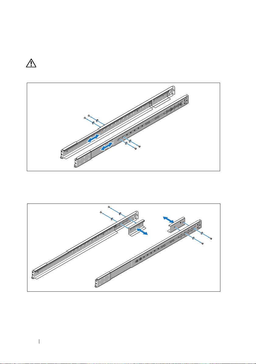
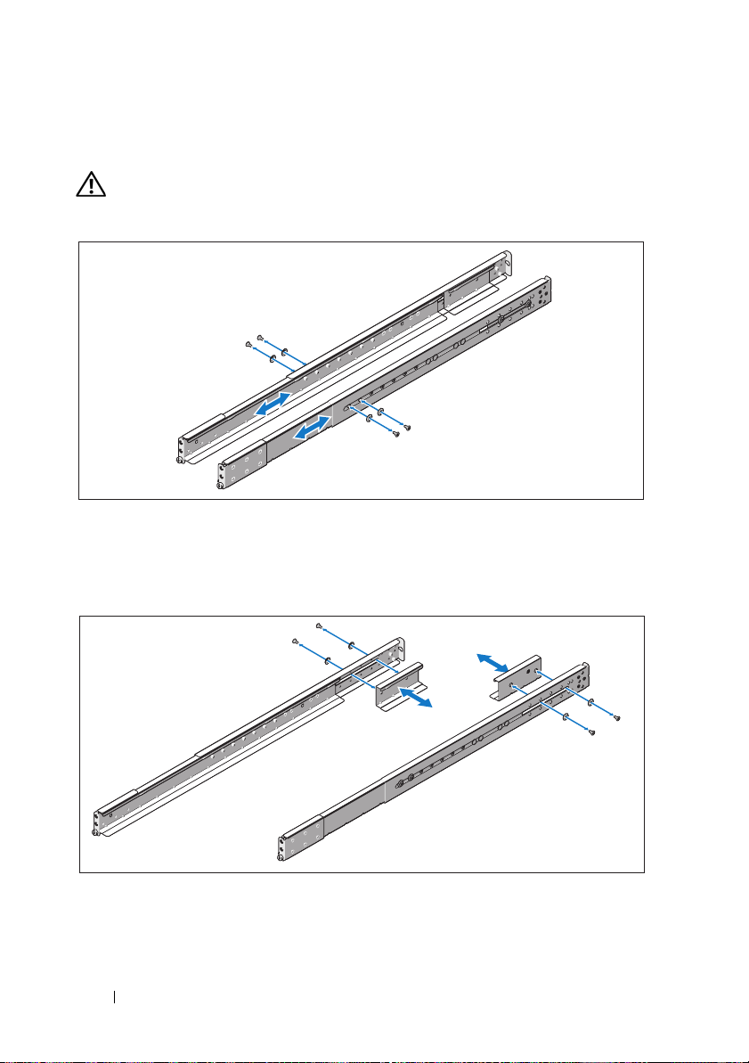
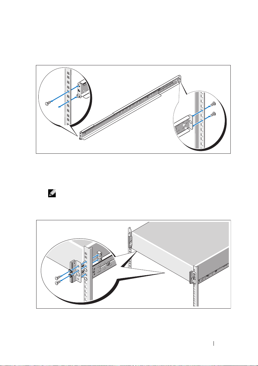
1
Install the screw with the washer into the selected hole of the rail to set
the travel stop position.
WARNING: The travel stop position is intended for repositioning your grip
for system removal. It is not intended for service.
2
If the extension brackets (optional) prevent the installation of rails in the
rack, remove the extension bracket screws to remove the extension bracket.
4 Getting Started With Your System
Page 7

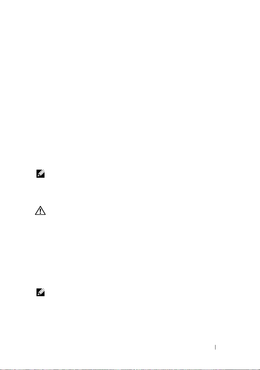
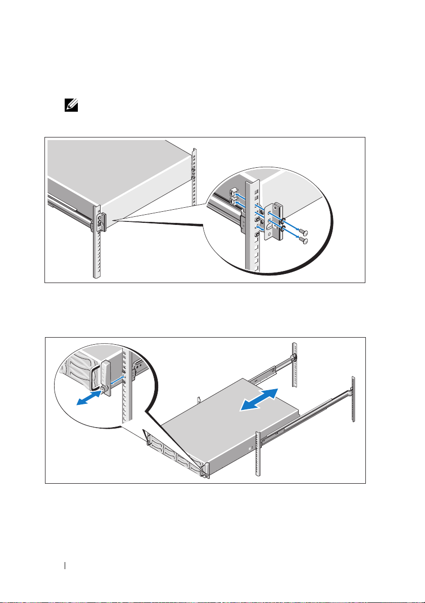
3
Secure the rails to the front of the rack using two screws and to the back of
the rack using four screws.
4
Slide the system into the rack.
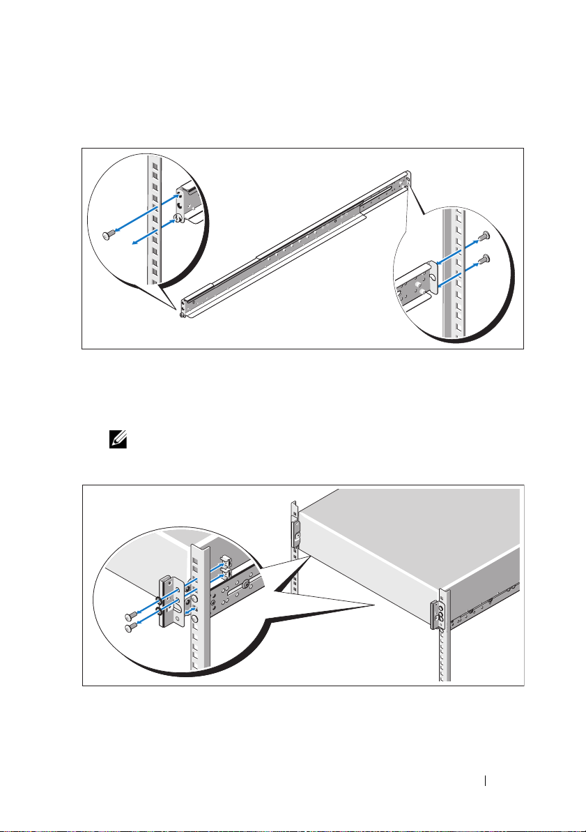
5
If present, remove the two chassis stabilizer shipping brackets (optional)
from the rack.
NOTE: To transport systems already installed in the rack, ensure that
the two chassis stabilizer shipping brackets (optional) are in place.
Getting Started With Your System 5
Page 8

6
Tighten the thumbscrews to secure the ears of the system to the front of
the rack.
Installing the Tool-Less Rail Solution
WARNING: Whenever you need to lift the system, get others to assist you.
To avoid injury, do not attempt to lift the system by yourself.
WARNING: The system is not fixed to the rack or mounted on the rails.
To avoid personal injury or damage to the system, you must adequately support
the system during installation and removal.
WARNING: To avoid a potential electrical shock hazard, a third wire safety
grounding conductor is necessary for the rack installation. The rack equipment
must provide sufficient airflow to the system to maintain proper cooling.
CAUTION: When installing rails in a square-hole rack it is important to ensure
that the square peg slides through the square holes.
6 Getting Started With Your System
Page 9
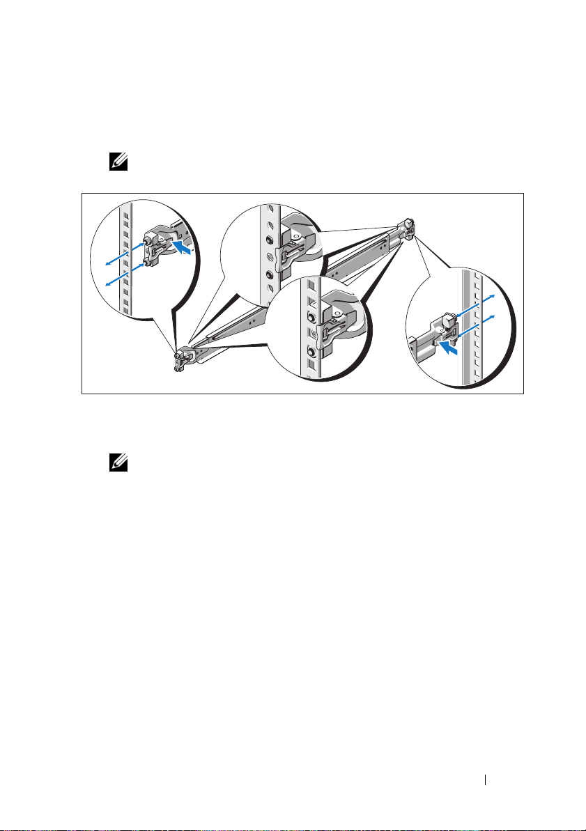
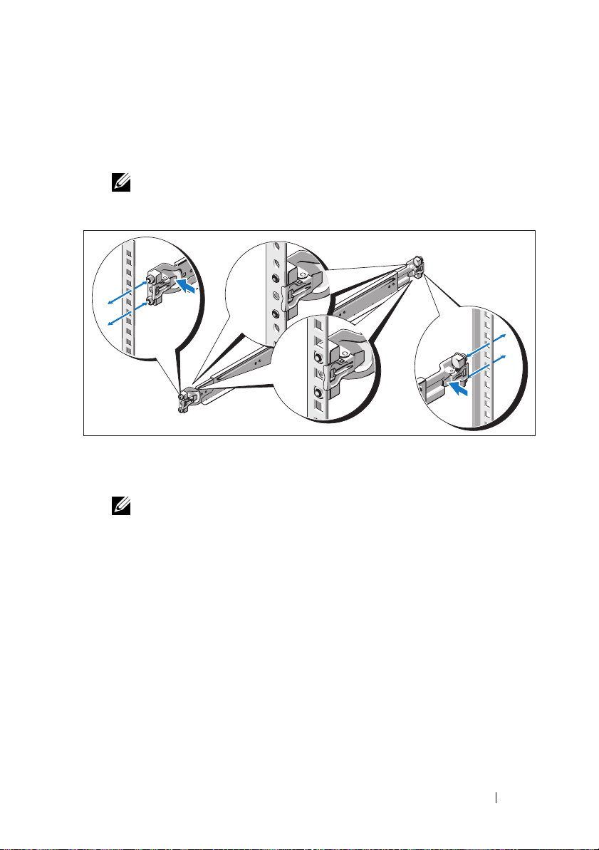
1
Align the end pieces of the rails on the vertical rack flanges to seat the
pegs in the bottom hole of the first U and the top hole of the second U.
Engage the back end of the rail until the latch locks in place.
NOTE: The rails can be used in both square-hole and round-hole racks.
2
Repeat step 1 to position and seat the front end piece on the vertical
flange.
NOTE: To remove the rails, pull on the latch release button on the end piece
midpoint and unseat each rail.
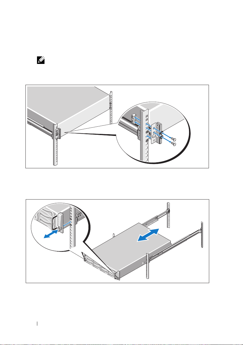
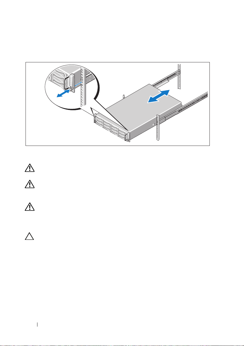
3
Slide the system into the rack.
Getting Started With Your System 7
Page 10

4
If present, remove the chassis stabilizer shipping bracket (optional)
from the rack.
NOTE: To transport systems already installed in the rack, ensure that
the chassis stabilizer shipping bracket (optional) is in place.
5
Tighten the thumbscrews to secure the ears of system to the front
of the rack.
8 Getting Started With Your System
Page 11
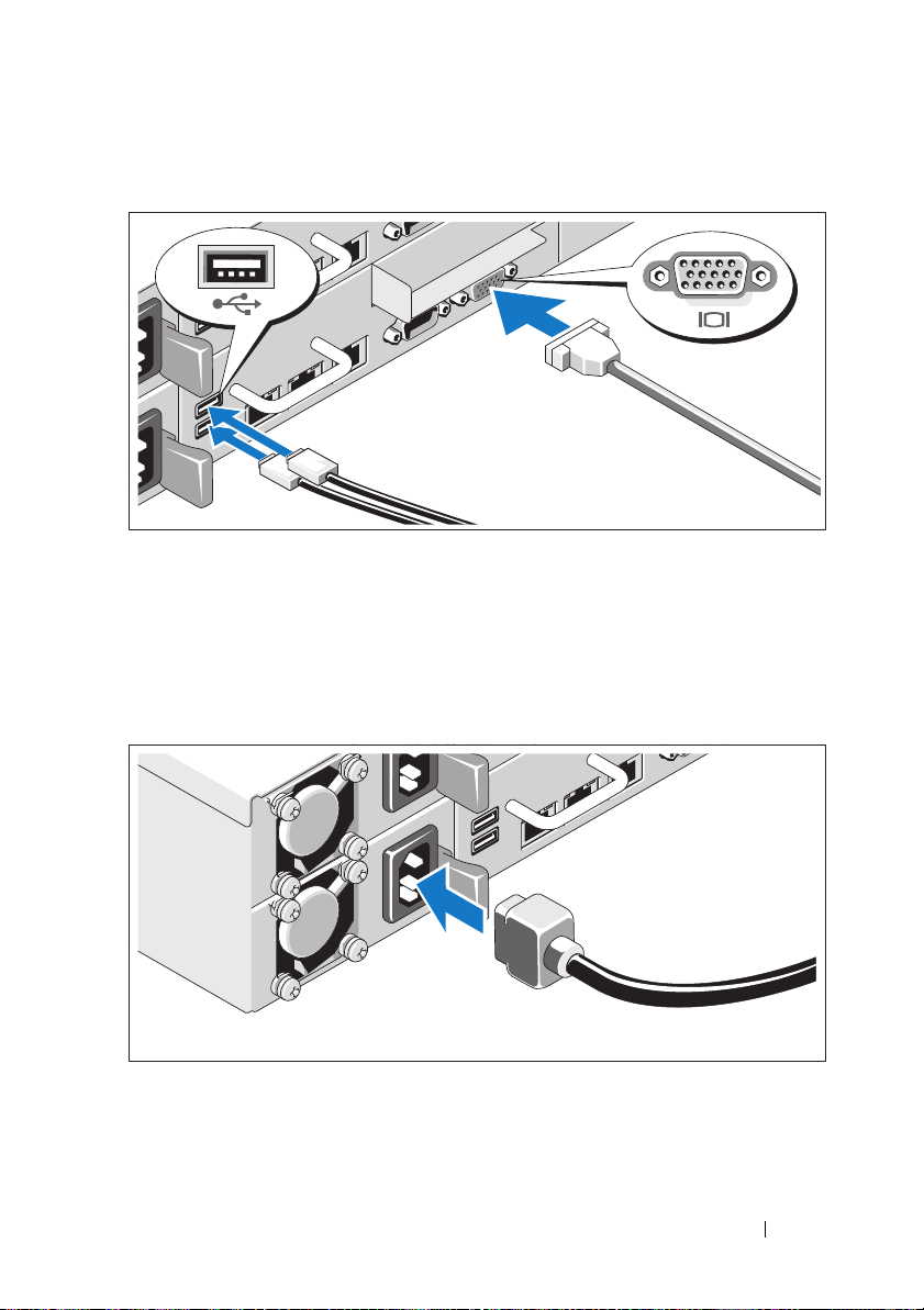
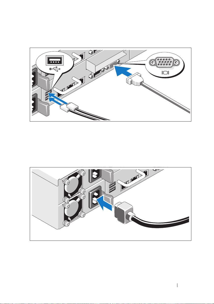
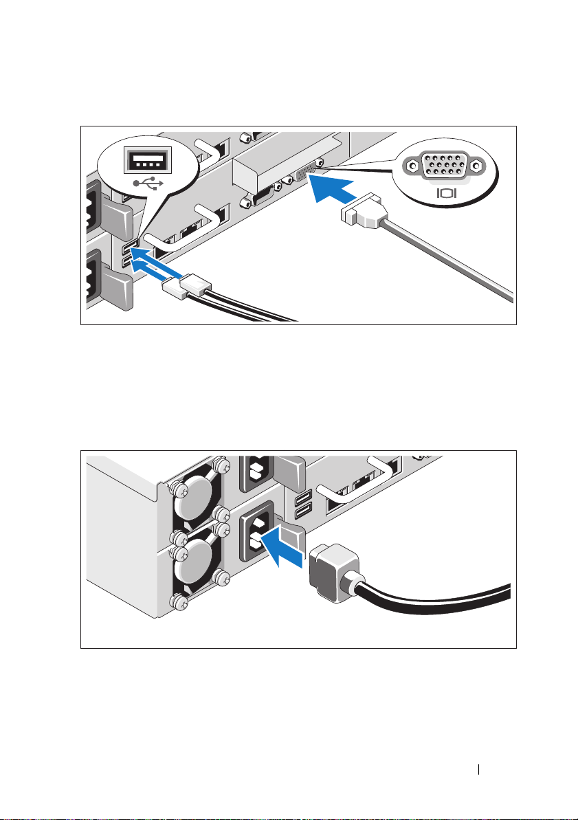
Optional – Connecting the Keyboard, Mouse, and Monitor
Connect the keyboard, mouse, and monitor (optional).
The connectors on the back of your system have icons indicating which cable
to plug into each connector. Be sure to tighten the screws (if any) on the
monitor's cable connector.
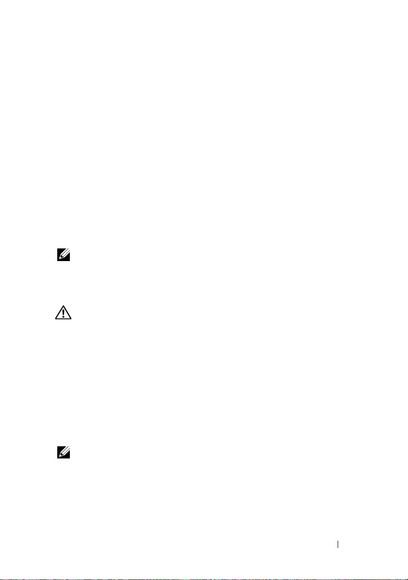
Connecting the Power Cable(s)
Connect the system’s power cable(s) to the system and, if a monitor is used,
connect the monitor’s power cable to the monitor. Plug the other end of the
power cables into a grounded electrical outlet or a separate power source such
as an uninterrupted power supply or a power distribution unit.
Getting Started With Your System 9
Page 12

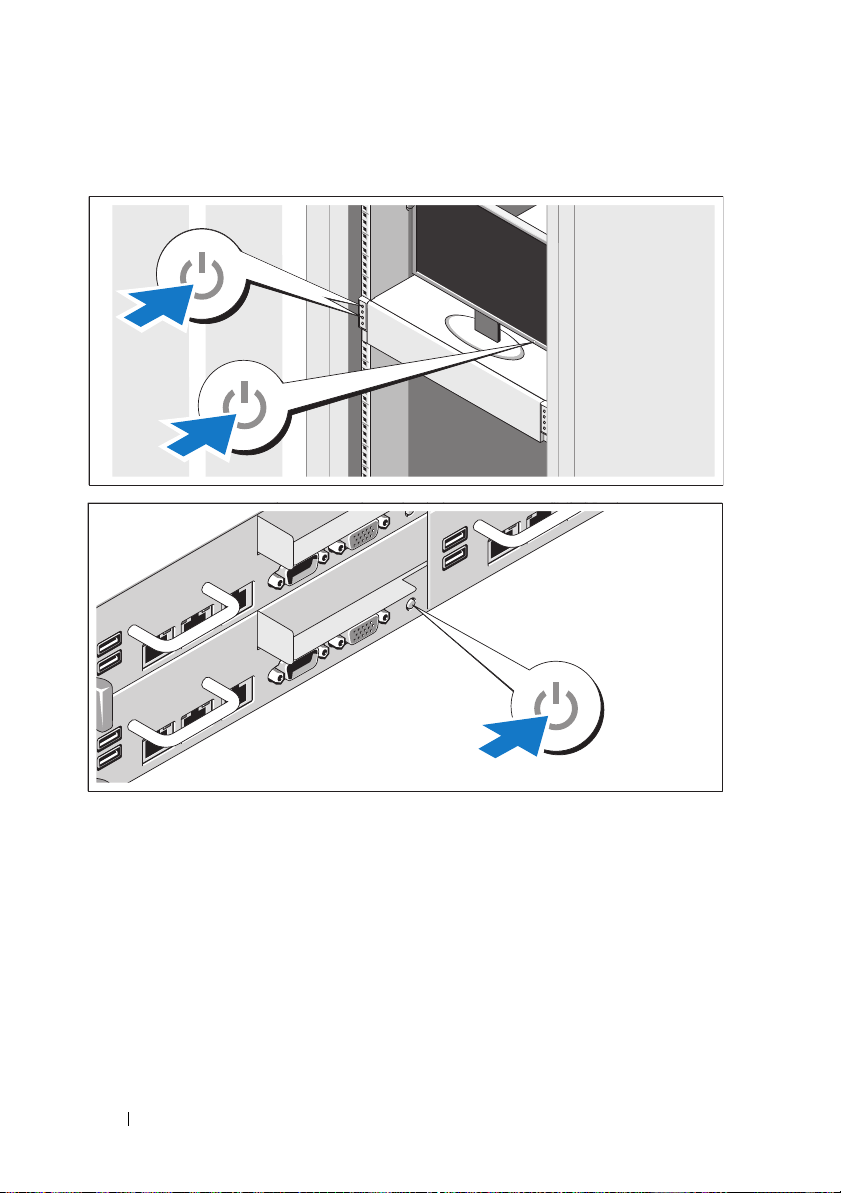
Turning On the System
Press the power button(s) either on the front or back of the system
and the monitor. The power indicators should light.
10 Getting Started With Your System
Page 13
Complete the Operating System Setup
To install an operating system for the first time, see the installation and
configuration documentation for your operating system. Be sure the
operating system is installed before installing hardware or software not
purchased with the system.
Supported Operating Systems
•Red Hat® Enterprise Linux® 5.4 Standard edition (x86_64)
• Red Hat Enterprise Linux 5.4 Standard edition (x86_32)
®
•SUSE
•VMware
•Citrix
NOTE: For the latest information on supported operating systems,
see support.dell.com.
Linux Enterprise Server 11 (x86_64)
®
ESX Server 4 Update 1
®
XenServer™ Enterprise edition 5.
x
Other Information You May Need
WARNING: See the safety and regulatory information that shipped with
your system. Warranty information may be included within this document
or as a separate document.
The Hardware Owner’s Manual provides information about system features
and describes how to troubleshoot the system and install or replace system
components. This document is available online at support.dell.com/manuals.
Dell systems management application documentation provides information
about installing and using the systems management software. This document
is available online at support.dell.com/manuals.
NOTE: Always check for updates on support.dell.com/manuals and read
the updates first because they often supersede information in other documents.
Getting Started With Your System 11
Page 14

Technical Specifications
Processor (Per System Board)
®
Processor type One or two Intel
processors (up to six core processors)
Expansion Bus (Per System Board)
Bus type PCI Express Generation 2
Expansion slots
PCIe
Mezzanine PCIe
Memory (Per System Board)
Architecture 1066 and 1333 MHz DDR3 registered
Memory module sockets Twelve 240-pin DIMMs
Memory module capacities 2 GB, 4 GB, or 8 GB
Minimum RAM 12 GB
Maximum RAM 96 GB
Drives
Hard drives Up to twelve 3.5-inch, hot-swappable
One x16, half-length, half-height
One x8, custom slot
memory modules with ECC
SAS/SATA drives or up to twenty four
2.5-inch, hot-swappable SAS/SATA/SSD
drives
Xeon® 5500 or 5600 series
Connectors (Per System Board)
Back
NIC
Serial
USB
Video
KVM over IP Port
Two RJ-45 (10/100/1000 Mbps Ethernet)
9-pin, DTE, 16550-compatible
Two 4-pin, USB 2.0-compliant
15-pin VGA
Dedicated Ethernet port for remote
management access
12 Getting Started With Your System
Page 15

Video (Per System Board)
Video type AST2050 video controller; VGA connector
Video memory 8 MB
Power
AC power supply (per power supply)
Wattage
Vo lt ag e
Heat dissipation
Wattage
Vo lt ag e
Heat dissipation
Wattage
Vo lt ag e
Heat dissipation
Wattage
Vo lt ag e
Heat dissipation
Maximum inrush current
Batteries (per system board)
System battery
RAID battery (optional) 3.7 V lithium ion battery pack
470 W
100–240 VAC, 50/60 Hz, 6.5–3.5 A
2390 BTU/hr maximum
750 W
100–240 VAC, 50/60 Hz, 9.5–5.0 A
3414 BTU/hr maximum
1024 W low line/1100 W high line
100–240 VAC, 50/60 Hz, 12.0–6.7 A
4575 BTU/hr maximum
1400 W high line
200–240 VAC, 50/60 Hz, 8.6–7.2 A
5432 BTU/hr maximum
Under typical line conditions and over the
entire system ambient operating range,
the inrush current may reach 25 A per power
supply for 10 ms or less
CR 2032 3.0-V lithium ion coin cell
Physical
Height 8.7 cm (3.4 in)
Width 44.8 cm (17.6 in)
Depth 75.1 cm (29.6 in)
Weight (maximum configuration) 36.5 kg (80.5 lb)
Weight (empty) 20 kg (44.1 lb)
Getting Started With Your System 13
Page 16

Environmental
NOTE: For additional information about environmental measurements for specific
system configurations, see www.dell.com/environmental_datasheets.
Temperature
Operating
10° to 35°C (50° to 95°F) with a maximum
temperature gradation of 10°C per hour
NOTE: For altitudes above 2950 feet,
the maximum operating temperature
is derated 1ºF/550 ft.
Storage
Relative humidity
Operating
Storage
Maximum vibration
Operating
Storage
Maximum shock
Operating
Storage
–40° to 65°C (–40° to 149°F) with
a maximum temperature gradation
of 20°C per hour
20% to 80% (noncondensing) with
a maximum humidity gradation
of 10% per hour
5% to 90% (noncondensing)
0.26 Grms at 5–350 Hz
1.54 Grms at 10–250 Hz for 15 min
One shock pulse in the positive z axis
(one pulse on each side of the system) of
31 G for 2.6 ms in the operational orientation
Six consecutively executed shock pulses in
the positive and negative x, y, and z axes
(one pulse on each side of the system) of
71 G for up to 2 ms
Six consecutively executed shock pulses
in the positive and negative x, y, and z axes
(one pulse on each side of the system) of
27 G faired square wave pulse with
velocity change at 235 inches/second
(597 centimeters/second)
14 Getting Started With Your System
Page 17

Environmental (continued)
Altitude
Operating
Storage
Airborne Contaminant Level
Class
Operating
Storage
Altitude
Operating
Storage
Airborne Contaminant Level
Class
–16 to 3,048 m (–50 to 10,000 ft)
NOTE: For altitudes above 2950 feet,
the maximum operating temperature
is derated 1ºF/550 ft.
–16 to 10,600 m (–50 to 35,000 ft)
G2 or lower as defined by ISA-S71.04-1985
One shock pulse in the positive z axis
(one pulse on each side of the system) of
31 G for 2.6 ms in the operational orientation
Six consecutively executed shock pulses in
the positive and negative x, y, and z axes
(one pulse on each side of the system) of
71 G for up to 2 ms
Six consecutively executed shock pulses
in the positive and negative x, y, and z axes
(one pulse on each side of the system) of
27 G faired square wave pulse with
velocity change at 235 inches/second
(597 centimeters/second)
–16 to 3,048 m (–50 to 10,000 ft)
NOTE: For altitudes above 2950 feet,
the maximum operating temperature
is derated 1ºF/550 ft.
–16 to 10,600 m (–50 to 35,000 ft)
G2 or lower as defined by ISA-S71.04-1985
Getting Started With Your System 15
Page 18

16 Getting Started With Your System
Page 19

Dell™ PowerEdge™ C6100
Guide de mise
en route
Modèle réglementaire XS23-TY3
Page 20

Remarques, précautions et avertissements
REMARQUE : une REMARQUE indique des informations importantes qui peuvent
vous aider à mieux utiliser votre ordinateur.
PRÉCAUTION : une PRÉCAUTION vous avertit d'un risque d'endommagement du
matériel ou de perte de données en cas de non-respect des instructions données.
AVERTISSEMENT : un AVERTISSEMENT vous avertit d'un risque
d'endommagement du matériel, de blessure corporelle ou de mort.
____________________
Les informations contenues dans ce document sont sujettes à modification sans préavis.
© 2010 Dell Inc. Tous droits réservés.
La reproduction de ce document, de quelque manière que ce soit, sans l'autorisation écrite
de Dell Inc. est strictement interdite.
Marques mentionnées dans ce document : Dell, le logo DELL et PowerEdge sont des marques
de Dell Inc. ; Intel et Xeon sont des marques déposées d'Intel Corporation aux États-Unis et dans
d'autres pays ; Red Hat and Red Hat Enterprise Linux sont des marques déposées de Red Hat, Inc.
aux États-Unis et/ou dans d'autres pays ; SUSE est une marque déposée appartenant à Novell, Inc.,
aux États-Unis et/ou dans d'autres pays ; VMware est une marque déposée appartenant à
VMware, Inc. aux États-Unis et/ou dans d'autres juridictions ; Citrix and XenServer sont des
marques de Citrix Systems, Inc. et/ou appartenant à ses filiales et peuvent être enregistrées au Bureau
des brevets et marques des États-Unis et d'autres pays.
D'autres marques commerciales et noms de marque peuvent être utilisés dans ce document
pour faire référence aux entités se réclamant de ces marques et de ces noms ou de leurs produits.
Dell Inc. dénie tout intérêt propriétaire vis-à-vis des marques et des noms de marque autres que
les siens.
Modèle réglementaire XS23-TY3
Février 2010 N/P 697N1 Rév. A00
Page 21
PRÉCAUTION : Lieux à accès restreint
Ce serveur est conçu pour être installé uniquement dans des lieux à accès
restreint tels que définis dans Cl. 1.2.7.3 de IEC 60950-1: 2001 où ces deux
conditions s'appliquent :
• Seuls peuvent avoir accès le
personnel d'entretien
et les
utilisateurs
qui
ont été informés des motifs des restrictions appliquées au lieu et
des précautions à prendre.
• L'accès, qui se fait par l'intermédiaire d'un
outil
ou d'un verrou et
d'une clé, ou par d'autres moyens de sécurité, est contrôlé par
le responsable en charge du lieu.
Installation et configuration
AVERTISSEMENT : avant de commencer la procédure suivante, lisez les
consignes de sécurité fournies avec le système. Respectez ces consignes.
Déballage du système
Sortez le système de son emballage et identifiez chaque élément.
Installation avec outils des rails
AVERTISSEMENT : demandez toujours de l'aide avant de soulever le système.
N'essayez pas de le soulever seul, car vous risqueriez de vous blesser.
AVERTISSEMENT : le système n'étant pas fixé au rack ni aux rails, vous devez
le soutenir adéquatement au cours de l'installation et du retrait pour éviter
de l'endommager ou de vous blesser.
AVERTISSEMENT : afin d'éviter un éventuel choc électrique, assurez-vous
que vous disposez d'un troisième conducteur de mise à la terre de sécurité des fils
pour l'installation du rack. L'équipement du rack doit assurer un flux d'air
suffisant pour bien refroidir le système.
Guide de mise en route 19
Page 22
1
Installez la vis avec la rondelle dans le trou sélectionné du rail afin
de définir la position d'arrêt.
AVERTISSEMENT : la position d'arrêt est conçue pour vous permettre de mieux
attraper le système lorsque vous le retirez. Elle n'est pas destinée à l'entretien.
2
Si les supports d'extension (en option) sont installés et empêchent
l'installation des rails dans le rack, retirez les supports d'extension
en retirant leur vis.
20 Guide de mise en route
Page 23
3
Fixez les rails à l'avant du rack à l'aide de deux vis et à l'arrière du rack
à l'aide de quatre vis.
4
Glissez le système dans le rack.
5
Si les deux supports d'expédition du stabilisateur de châssis (en option)
sont présents, retirez-les du rack.
REMARQUE : avant de transporter des systèmes déjà installés dans le rack,
assurez-vous que les deux supports d'expédition du stabilisateur de châssis
(en option) sont en place.
Guide de mise en route 21
Page 24

6
Serrez les vis à serrage à main afin de fixer les pattes du système à l'avant
du rack.
Installation sans outil des rails
AVERTISSEMENT : demandez toujours de l'aide avant de soulever le système.
N'essayez pas de le soulever seul, car vous risqueriez de vous blesser.
AVERTISSEMENT : le système n'étant pas fixé au rack ni aux rails, vous devez
le soutenir adéquatement au cours de l'installation et du retrait pour éviter de
l'endommager ou de vous blesser.
AVERTISSEMENT : afin d'éviter un éventuel choc électrique, assurez-vous
que vous disposez d'un troisième conducteur de mise à la terre de sécurité des fils
pour l'installation du rack. L'équipement du rack doit assurer un flux d'air
suffisant pour bien refroidir le système.
PRÉCAUTION : lorsque vous installez des rails dans un rack à trous carrés,
vérifiez bien que les taquets de fixation à tête carrée glissent bien dans les trous
carrés.
22 Guide de mise en route
Page 25
1
Alignez l'embout des rails avec les collerettes verticales pour que les taquets
de fixation s'insèrent dans le trou du bas de la première unité en U et le trou
du haut de la deuxième unité en U. Glissez l'arrière du rail jusqu'à
enclenchement du loquet.
REMARQUE : les rails peuvent être utilisés à la fois dans les trous carrés
et les trous ronds.
2
Répétez l'étape 1 pour positionner l'embout avant sur la collerette
verticale.
REMARQUE : pour retirer les rails, appuyez sur le bouton de dégagement
du loquet situé au milieu de l'embout et dégagez les rails un par un.
3
Glissez le système dans le rack.
Guide de mise en route 23
Page 26
4
Si les deux supports d'expédition du stabilisateur de châssis (en option)
sont présents, retirez-les du rack.
REMARQUE : avant de transporter des systèmes déjà installés dans le rack,
assurez-vous que les deux supports d'expédition du stabilisateur de châssis
(en option) sont en place.
5
Serrez les vis à serrage à main afin de fixer les pattes du système à l'avant
du rack.
24 Guide de mise en route
Page 27
Facultatif – Connexion du clavier, de la souris et du moniteur
Connectez le clavier, la souris et le moniteur (si nécessaire).
Aidez-vous des icônes des connecteurs situés à l'arrière du système pour
savoir où insérer chaque câble. N'oubliez pas de serrer les vis situées sur
le connecteur du câble du moniteur, s'il en est équipé.
Branchement du ou des câbles d'alimentation
Connectez le ou les câbles d'alimentation au système et, si vous utilisez
un moniteur, connectez son câble d'alimentation. Branchez ensuite l'autre
extrémité des câbles d'alimentation sur une prise de courant mise à la terre
ou sur une source d'alimentation autonome (onduleur [UPS] ou unité
de distribution de l'alimentation [PDU]).
Guide de mise en route 25
Page 28
Mise sous tension du système
Appuyez sur les boutons d'alimentation à l'avant ou à l'arrière du système
et du moniteur. Les voyants d'alimentation s'allument.
26 Guide de mise en route
Page 29
Finalisation de l'installation du système d'exploitation
Voir la documentation relative à l'installation et à la configuration du système
d'exploitation si vous installez celui-ci pour la première fois. Veillez à installer
le système d'exploitation avant tout élément matériel ou logiciel acheté
séparément.
Systèmes d'exploitation pris en charge
•Red Hat® Enterprise Linux® 5.4 Édition standard (x86_64)
• Red Hat Enterprise Linux 5.4 Édition standard (x86_32)
•SUSE
•VMware
•Citrix
®
Linux Enterprise Server 11 (x86_64)
®
ESX Server 4 Mise à jour 1
®
XenServer™, Édition Entreprise 5.x
REMARQUE : pour obtenir les informations les plus récentes sur les systèmes
d'exploitation pris en charge, rendez-vous sur le site support dell.com.
Autres informations utiles
AVERTISSEMENT : voir les informations sur la sécurité et les réglementations
fournies avec votre système. Les informations sur la garantie se trouvent dans
ce document ou dans un document distinct.
Le Manuel du propriétaire présente les fonctionnalités du système et
contient des informations de dépannage du système ainsi que des
instructions d'installation ou de remplacement des composants du système.
Il est disponible en ligne sur le site support.dell.com/manuals.
La documentation relative aux applications de gestion de systèmes Dell
donne des informations sur l'installation et l'utilisation du logiciel de gestion
de systèmes. Il est disponible en ligne sur le site support.dell.com/manuals.
REMARQUE : vérifiez toujours si des mises à jour sont disponibles sur le site
support.dell.com/manuals et lisez-les en premier, car elles remplacent souvent
les informations contenues dans les autres documents.
Guide de mise en route 27
Page 30

Caractéristiques techniques
Processeur (par carte système)
®
Type de processeur Un ou deux processeurs Intel
5500 ou 5600 (jusqu'à six processeurs cœurs)
Bus d'extension (par carte système)
Type de bus PCI Express 2ème génération
Logements d'extension
PCIe
Mezzanine PCIe
Mémoire (par carte système)
Architecture Barrettes de mémoire enregistrée DDR3 1066
Connecteurs de barrettes de mémoire Douze DIMM à 240 broches
Capacité des barrettes de mémoire 2 Go, 4 Go ou 8 Go
RAM minimale 12 Go
RAM maximale 96 Go
Lecteurs
Disques durs Jusqu'à douze lecteurs SAS/SAT 3,5 pouces,
Une x16, mi-longueur, mi-hauteur
Une x8, emplacement personnalisé
et 1333 MHz avec ECC
remplaçables à chaud ou jusqu'à vingt-quatre
lecteurs SAS/SATA/SSD 2,5 pouces,
remplaçables à chaud
Xeon® série
28 Guide de mise en route
Page 31

Connecteurs (par carte système)
Arrière
Carte réseau
Série
USB
Vidéo
CVS sur Port IP
Vidéo (par carte système)
Type de vidéo Contrôleur vidéo AST2050 ; connecteur VGA
Mémoire vidéo 8 Mo
Alimentation
Bloc d'alimentation en CA (selon la tension en vigueur)
Puissance
Te ns i on
Dissipation thermique
Puissance
Te ns i on
Dissipation thermique
Puissance
Te ns i on
Dissipation thermique
Puissance
Te ns i on
Deux prises Ethernet RJ-45
(10/100/1000 Mbit/s)
Un connecteur DTE à 9 broches,
compatible 16550
Deux connecteurs à 4 broches,
compatibles USB 2.0
Un connecteur VGA à 15 broches
Port Ethernet dédié pour accès de gestion
à distance
470 W
100–240 VAC, 50/60 Hz, 6,5–3,5 A
2390 BTU/heure au maximum
750 W
100–240 VAC, 50/60 Hz, 9,5–5,0 A
3414 BTU/heure au maximum
1024 W basse tension/1100 W haute tension
100–240 VAC, 50/60 Hz, 12,0–6,7 A
4575 BTU/heure au maximum
1400 W haute tension
200–240 VAC, 50/60 Hz, 8,6–7,2 A
Guide de mise en route 29
Page 32

Alimentation (suite)
Dissipation thermique
Courant d'appel maximal
Piles (par carte système)
Pile du système
Batterie RAID (en option) Pack au lithium-ion (3,7 V)
Caractéristiques physiques
Hauteur 8,7 cm (3,4 pouces)
Largeur 44,8 cm (17,6 pouces)
Profondeur 75,1 cm (29,6 pouces)
Poids (configuration maximale) 36,5 kg (80,5 livres)
Poids (à vide) 20 kg (44,1 livres)
Environnement
5432 BTU/heure au maximum
Dans des conditions de lignes typiques
et dans toute la gamme ambiante de
fonctionnement du système, l'appel de
courant peut atteindre 25 A par bloc
d'alimentation pendant un maximum
de 10 ms.
Pile bouton au lithium-ion CR 2032 (3 V)
REMARQUE : pour des informations supplémentaires sur les mesures
environnementales liées aux différentes configurations du système,
voir www.dell.com/environmental_datasheets.
Température
En fonctionnement
De 10 à 35 °C (de 50 à 95 °F) avec un
gradient thermique maximal de 10 °C
par heure
REMARQUE : pour les altitudes supérieures
à 900 mètres (2 950 pieds), la température
maximale de fonctionnement est réduite de
0,55 °C (1 °F) tous les 168 mètres (550 pieds).
Stockage
De -40 à 65 °C (de -40 à 149 °F) avec un
gradient thermique maximal de 20 °C par
heure
30 Guide de mise en route
Page 33

Environnement (suite)
Humidité relative
En fonctionnement
Stockage
Tolérance maximale aux vibrations
En fonctionnement
Stockage
Choc maximal
En fonctionnement
Stockage
Altitude
En fonctionnement
Stockage
De 20 à 80 % (sans condensation) avec
un gradient d'humidité maximal de 10 %
par heure
5% à 90% (sans condensation)
0,26 Grms à 5–350 Hz
1,54 Grms avec un balayage de 10 à 250 Hz
pendant 15 minutes
Une impulsion de choc de 31 G pendant
un maximum de 2,6 ms sur l'axe z positif
(une impulsion de chaque côté du système)
Six chocs consécutifs de 71 G pendant un
maximum de 2 ms en positif et négatif sur
les axes x, y et z (une impulsion de chaque
côté du système)
Six chocs consécutifs sur les axes x, y et z en
positif et négatif (une impulsion de chaque
côté du système) d'impulsion d'onde carrée
de 27 G avec un changement de vitesse de
597 cm/s (235 po/s)
De -16 à 3 048 m (de -50 à 10 000 pieds)
REMARQUE : pour les altitudes supérieures
à 900 mètres (2 950 pieds), la température
maximale de fonctionnement est réduite de
0,55 °C (1 °F) tous les 168 mètres (550 pieds).
De -16 à 10 600 m (-50 à 35 000 pieds)
Guide de mise en route 31
Page 34

Environnement (suite)
Contaminants en suspension dans l'air
Classe
En fonctionnement
Stockage
Altitude
En fonctionnement
Stockage
Contaminants en suspension dans l'air
Classe
G2 ou inférieure selon la norme
ISA-S71.04-1985
Une impulsion de choc de 31 G pendant
un maximum de 2,6 ms sur l'axe z positif
(une impulsion de chaque côté du système)
Six chocs consécutifs de 71 G pendant un
maximum de 2 ms en positif et négatif sur
les axes x, y et z (une impulsion de chaque
côté du système)
Six chocs consécutifs sur les axes x, y et z en
positif et négatif (une impulsion de chaque
côté du système) d'impulsion d'onde carrée
de 27 G avec un changement de vitesse de
597 cm/s (235 po/s)
De -16 à 3 048 m (de -50 à 10 000 pieds)
REMARQUE : pour les altitudes supérieures
à 900 mètres (2 950 pieds), la température
maximale de fonctionnement est réduite de
0,55 °C (1 °F) tous les 168 mètres (550 pieds).
De -16 à 10 600 m (-50 à 35 000 pieds)
G2 ou inférieure selon la norme
ISA-S71.04-1985
32 Guide de mise en route
Page 35

Dell™ PowerEdge™ C6100
Primeiros passos
com o sistema
Modelo normativo XS23-TY3
Page 36

Notas, Avisos e Advertências
NOTA: Uma NOTA fornece informações importantes que o ajudam a utilizar melhor
o computador.
AVISO: Um AVISO indica um potencial de danos ao hardware ou a perda de dados
se as instruções não forem seguidas.
ADVERTÊNCIA: Uma ADVERTÊNCIA indica a possibilidade de danos
à propriedade, de lesões corporais ou até mesmo de morte.
____________________
As informações contidas neste documento estão sujeitas a alterações sem aviso prévio.
© 2010 Dell Inc. Todos os direitos reservados.
Qualquer forma de reprodução deste material sem a permissão por escrito da Dell Inc.
é expressamente proibida.
Marcas comerciais usadas neste texto: Dell, o logotipo DELL e PowerEdge são marcas comerciais
da Dell Inc.; Intel e Xeon são marcas registradas da Intel Corporation nos EUA e em outros países;
Red Hat e Red Hat Enterprise Linux são marcas registradas da Red Hat, Inc. nos Estados Unidos e
em outros países; SUSE é marca registrada da Novell, Inc. nos Estados Unidos; VMware é marca
registrada da VMware, Inc. nos Estados Unidos e/ou em outras jurisdições; Citrix e XenServer são
marcas registradas da Citrix Systems, Inc. e/ou de suas subsidiárias e podem ser registradas no
Escritório de Marcas e Patentes dos Estados Unidos e em outros países.
Outras marcas e nomes comerciais podem ser usados neste documento como referência às entidades
que reivindicam essas marcas e nomes ou a seus produtos. A Dell Inc. renuncia ao direito de qualquer
participação em nomes e marcas comerciais que não sejam de sua propriedade.
Modelo normativo XS23-TY3
Fevereiro de 2010 N/P 697N1 Rev. A00
Page 37

AVISO: Local de acesso restrito
Este servidor destina-se a instalação apenas em locais de acesso restrito,
conforme definido na cláusula 1. 1.2.7.3 da IEC 60950-1: 2001, segundo
a qual as duas condições a seguir se aplicam:
• O acesso pode ser obtido apenas por
usuários
orientados sobre os motivos das restrições aplicadas ao local
profissionais de manutenção
ou
e sobre todas as precauções que devem ser adotadas.
• O acesso deverá ser feito com o uso de uma
ferramenta
ou de uma trava
com chave, ou outros dispositivos de segurança, sendo controlado pela
autoridade responsável pelo local.
Instalação e configuração
ADVERTÊNCIA: Antes de executar o procedimento a seguir, leia e siga
as instruções de segurança fornecidas com o sistema.
Como remover o sistema da embalagem
Remova o sistema da embalagem e identifique cada item.
Como instalar a solução de trilhos usinados
ADVERTÊNCIA: Sempre que precisar levantar o sistema, solicite a ajuda
de outras pessoas. Para evitar lesões, não tente levantá-lo sozinho.
ADVERTÊNCIA: O sistema não é preso ao rack nem montado nos trilhos.
Para evitar lesões pessoais e danos ao sistema, apoie o rack do sistema de modo
adequado durante a instalação ou remoção.
ADVERTÊNCIA: Para evitar possíveis riscos de choque elétrico, é necessário
usar um condutor de segurança aterrado na instalação do rack. O equipamento
do rack deve fornecer ventilação suficiente para que o sistema mantenha o grau
de refrigeração adequado.
Primeiros passos com o sistema 35
Page 38

1
Insira o parafuso com a arruela no orifício selecionado do trilho
para definir a posição de travamento para transporte.
ADVERTÊNCIA: A posição de travamento para transporte deve ser usada
para reposicionar o prendedor para remoção do sistema. Ela não deve ser usada
em serviço.
2
Se houver suportes de extensão (opcionais) que impeçam a instalação
dos trilhos no rack, remova os parafusos do suporte de extensão para
remover o suporte de extensão.
36 Primeiros passos com o sistema
Page 39
3
Para prender os trilhos na parte da frente do rack, use dois parafusos e,
para prendê-los na parte de trás do rack, use quatro parafusos.
4
Deslize o sistema sobre o rack.
5
Se estiverem presentes, remova do rack os dois suportes opcionais
de estabilização do chassi, usados para o envio.
NOTA: Para transportar sistemas já instalados no rack, verifique se os dois
suportes de envio de estabilização do chassi (opcionais) estão no lugar certo.
Primeiros passos com o sistema 37
Page 40
6
Enrosque os parafusos de aperto manual para prender as abas do sistema
ao rack.
Como instalar a solução de trilhos não usinados
ADVERTÊNCIA: Sempre que precisar levantar o sistema, solicite a ajuda
de outras pessoas. Para evitar lesões, não tente levantá-lo sozinho.
ADVERTÊNCIA: O sistema não é preso ao rack nem montado nos trilhos.
Para evitar lesões pessoais e danos ao sistema, apoie o rack do sistema de modo
adequado durante a instalação ou remoção.
ADVERTÊNCIA: Para evitar possíveis riscos de choque elétrico, é necessário
usar um condutor de segurança aterrado na instalação do rack. O equipamento
do rack deve fornecer ventilação suficiente para que o sistema mantenha o grau
de refrigeração adequado.
AVISO: Ao instalar os trilhos em um rack de orifício retangular é importante
garantir que o pino retangular deslize pelos orifícios retangulares.
38 Primeiros passos com o sistema
Page 41

1
Alinhe as extremidades traseiras dos trilhos nas guias verticais do rack para
instalar os pinos no orifício inferior do primeiro U e no orifício superior
do segundo U. Prenda a extremidade traseira do trilho até encaixar a trava.
NOTA: Os trilhos podem ser usados em rack de orifício retangular e redondo.
2
Repita etapa 1 para posicionar e instalar a extremidade frontal na guia
vertical.
NOTA: Para remover os trilhos, puxe o botão para liberar a trava no centro
da extremidade traseira e desinstale cada trilho.
3
Deslize o sistema sobre o rack.
Primeiros passos com o sistema 39
Page 42
4
Se estiverem presentes, remova do rack os dois suportes opcionais
de estabilização do chassi, usados para o envio.
NOTA: Para transportar sistemas já instalados no rack, verifique se os dois
suportes de envio de estabilização do chassi (opcionais) estão no lugar certo.
5
Enrosque os parafusos de aperto manual para prender as abas do sistema
ao rack.
40 Primeiros passos com o sistema
Page 43
Opcional – Como conectar teclado, mouse e monitor
Conecte o teclado, o mouse e o monitor (opcional).
Os conectores na parte traseira do sistema têm ícones que indicam
quais cabos devem ser ligados a cada conector. Certifique-se de apertar
os parafusos (se houver algum) no conector do cabo do monitor.
Como conectar cabo(s) de alimentação
Conecte o(s) cabo(s) de alimentação ao sistema e, se for usado um monitor,
conecte o(s) cabo(s) de alimentação ao monitor. Conecte a outra extremidade dos cabos de alimentação a uma tomada elétrica aterrada ou a uma
fonte de alimentação separada, como uma fonte de alimentação ininterrupta
ou a uma unidade de distribuição de energia.
Primeiros passos com o sistema 41
Page 44

Como ligar o sistema
Pressione o botão liga/desliga localizado na parte da frente ou de trás
do sistema e do monitor. As luzes indicadoras de alimentação acenderão.
42 Primeiros passos com o sistema
Page 45

Conclua a instalação do sistema operacional
Para instalar um sistema operacional pela primeira vez, consulte a
documentação de instalação e configuração do sistema operacional.
Certifique-se de que o sistema operacional esteja instalado antes de instalar
qualquer hardware ou software que não tenha sido adquirido com o sistema.
Sistemas operacionais compatíveis
•Red Hat® Enterprise Linux® 5.4, edição Standard (x86_64)
• Red Hat Enterprise Linux 5,4, edição Standard (x86_32)
®
•SUSE
•VMware
•Citrix
NOTA: Para obter as informações mais recentes sobre os sistemas operacionais
compatíveis, consulte o site support.dell.com (em inglês).
Linux Enterprise Server 11 (x86_64)
®
ESX Versão 4, Atualização 1
®
XenServer™ Enterprise, edição 5.
x
Outras informações úteis
ADVERTÊNCIA: Consulte as informações de regulamentação e de segurança
fornecidas com o sistema. As informações sobre garantia podem estar incluídas
neste documento ou serem fornecidas em um documento separado.
O Manual do proprietário de hardware fornece informações sobre os recursos
do sistema e descreve como solucionar problemas do sistema e instalar ou
trocar componentes. Este documento está disponível online em
support.dell.com/manuals (em inglês).
A documentação do aplicativo de gerenciamento de sistemas Dell fornece
informações sobre como instalar e usar o software de gerenciamento
de sistemas. Este documento está disponível online em
support.dell.com/manuals (em inglês).
NOTA: Verifique sempre se há atualizações disponíveis no site
support.dell.com/manuals (em inglês) e leia primeiro as atualizações, pois estas
geralmente substituem informações contidas em outros documentos.
Primeiros passos com o sistema 43
Page 46

Especificações técnicas
Processador (por placa de sistema)
Tipo de processador Um ou dois processadores da série Intel
Barramento de expansão (por placa de sistema)
Tipo de barramento PCI Express Geração 2
Slots de expansão
PCIe
PCIe para mezanino
Memória (por placa de sistema)
Arquitetura Módulos de memória registrada DDR3
Soquetes dos módulos de memória 12 DIMMs de 240 pinos
Capacidades dos módulos de
memória
Mínimo de RAM 12 GB
Máximo de RAM 96 GB
®
5500 ou 5600 (até processadores
Xeon
six-core)
1 slot x16 de meia altura e meio comprimento
1 slot x8 padrão
de 1066 e 1333 MHz com ECC
2 GB, 4 GB ou 8 GB
®
Unidades
Discos rígidos Até 12 unidades SAS/SATA de 3,5 polegadas
com conexão automática ou
até 24 unidades SAS/SATA/SSD
de 2,5 polegadas com conexão automática
44 Primeiros passos com o sistema
Page 47

Conectores (por placa de sistema)
Tr a se i r o s
Placa de rede
Serial
USB
Vídeo
KVM sobre Porta IP
Vídeo (por placa de sistema)
Tipo de vídeo Controladora de vídeo AST2050; conector
Memória de vídeo 8 MB
Alimentação
Fonte de alimentação CA (por fonte de alimentação)
Potência
Te ns ã o
Dissipação de calor
Potência
Te ns ã o
Dissipação de calor
Potência
Te ns ã o
Dissipação de calor
Potência
Te ns ã o
Dois conectores Ethernet RJ-45
10/100/1000 Mbps
DTE de 9 pinos, compatível com 16550
Dois conectores de 4 pinos, compatíveis
com USB 2.0
VGA de 15 pinos
Porta Ethernet dedicada para acesso
a gerenciamento remoto
VGA
470 W
100–240 VCA, 50/60 Hz, 6,5–3,5 A
2390 BTU/h máximo
750 W
100–240 VCA, 50/60 Hz, 9,5–5,0 A
3414 BTU/h máximo
1024 W linha baixa /1100 W linha alta
100–240 VCA, 50/60 Hz, 12,0–6,7 A
4575 BTU/h máximo
1400 W linha alta
200–240 VCA, 50/60 Hz, 8,6–7,2 A
Primeiros passos com o sistema 45
Page 48

Alimentação (continuação)
Dissipação de calor
Corrente de entrada máxima
Baterias (por placa de sistema)
Bateria do sistema
Bateria RAID (opcional) Pacote de bateria de íon de lítio de 3,7-V
Características físicas
Altura 8,7 cm (3,4 pol)
Largura 44,8 cm (17,6 pol)
Profundidade 75,1 cm (29,6 pol)
Peso (com a configuração máxima) 36,5 kg (80,5 lb)
Peso (vazio) 20 kg (44,1 lb)
Ambientais
5432 BTU/h máximo
Sob condições de linha típicas e dentro
da faixa de temperatura ambiente de
funcionamento do sistema, a corrente
de entrada poderá atingir 25 A por fonte
de alimentação por 10 ms ou menos.
Bateria tipo moeda de íons de lítio, CR 2032
de 3,0 V
NOTA: Para obter informações adicionais sobre as medições ambientais
para configurações de sistema específicas, visite o site
www.dell.com/environmental_datasheets (em inglês).
Temperatura
Operacional
10° a 35° C (50° a 95° F) com variação
máxima de 10° C por hora
NOTA: Para altitudes acima de 900 m (2.950
pés), a temperatura de operação máxima é
avaliada em 1° C/300 m (1° F/550 pés).
Armazenamento
-40° C a 65° C com variação máxima de 20° C
por hora
46 Primeiros passos com o sistema
Page 49

Ambientais (continuação)
Umidade relativa
Operacional
Armazenamento
Vibração máxima
Operacional
Armazenamento
Choque máximo
Operacional
Armazenamento
Altitude
Operacional
Armazenamento
20% a 80% (sem condensação) com variação
máxima de 10% por hora
5% a 90% (sem condensação)
0,26 Grms a 5–350 Hz
1,54 Grms a 10–250 Hz por 15 minutos
Um pulso de choque no eixo z positivo
(um pulso de cada lado do sistema) de 31 G
por 2,6 ms na orientação operacional
Seis pulsos de choque aplicados consecutivamente nos eixos x, y e z positivos e negativos
(um pulso de cada lado do sistema) de 71 G
por até 2 ms
Seis pulsos de choque aplicados consecutivamente nos eixos x, y e z positivos e negativos
(um pulso de cada lado do sistema) de onda
quadrada de 27 G com variação de velocidade
de 235 polegadas/segundo
(597 centímetros/segundo)
–16 m a 3.048 m (–50 a 10.000 pés)
NOTA: Para altitudes acima de 900 m
(2.950 pés), a temperatura de operação máxima
é avaliada em 1° C/300 m (1° F/550 pés).
–16 m a 10.600 m (–50 to 35.000 pés)
Primeiros passos com o sistema 47
Page 50

Ambientais (continuação)
Nível de poluentes transportados pelo ar
Classe
Operacional
Armazenamento
Altitude
Operacional
Armazenamento
Nível de poluentes transportados pelo ar
Classe
G2 ou inferior, conforme definido pela norma
ISA-S71.04-1985
Um pulso de choque no eixo z positivo
(um pulso de cada lado do sistema) de 31 G
por 2,6 ms na orientação operacional
Seis pulsos de choque aplicados consecutivamente nos eixos x, y e z positivos e negativos
(um pulso de cada lado do sistema) de 71 G
por até 2 ms
Seis pulsos de choque aplicados consecutivamente nos eixos x, y e z positivos e negativos
(um pulso de cada lado do sistema) de onda
quadrada de 27 G com variação de velocidade
de 235 polegadas/segundo
(597 centímetros/segundo)
–16 m a 3.048 m (–50 a 10.000 pés)
NOTA: Para altitudes acima de 900 m
(2.950 pés), a temperatura de operação máxima
é avaliada em 1° C/300 m (1° F/550 pés).
–16 m a 10.600 m (–50 to 35.000 pés)
G2 ou inferior, conforme definido pela norma
ISA-S71.04-1985
48 Primeiros passos com o sistema
Page 51

Dell™ PowerEdge™ C6100
Procedimientos iniciales
con el sistema
Modelo reglamentario XS23-TY3
Page 52
Notas, precauciones y avisos
NOTA: Una NOTA proporciona información importante que le ayudará a utilizar
mejor el ordenador.
PRECAUCIÓN: Un mensaje de PRECAUCIÓN indica la posibilidad de daños
en el hardware o la pérdida de datos si no se siguen las instrucciones.
AVISO: Un mensaje de AVISO indica el riesgo de daños materiales,
lesiones o incluso la muerte.
____________________
La información contenida en este documento puede modificarse sin previo aviso.
© 2010 Dell Inc. Todos los derechos reservados.
Queda estrictamente prohibida la reproducción de este material en cualquier forma sin la
autorización por escrito de Dell Inc.
Marcas comerciales utilizadas en este texto: Dell, el logotipo de DELL y PowerEdge son marcas
comerciales de Dell Inc.; Intel y Xeon son marcas comerciales registradas de Intel Corporation en
los Estados Unidos y en otros países; Red Hat y Red Hat Enterprise Linux son marcas comerciales
registradas de Red Hat, Inc. en los Estados Unidos y en otros países; SUSE es una marca comercial
registrada de Novell, Inc. en los Estados Unidos y en otros países; VMware es una marca comercial
registrada de VMware, Inc. en los Estados Unidos o en otras jurisdicciones; Citrix y XenServer son
marcas comerciales de Citrix Systems, Inc. o de una o varias de sus filiales, y pueden estar registradas
en la Oficina de Patentes y Marcas de los Estados Unidos y en otros países.
Otras marcas y otros nombres comerciales pueden utilizarse en este documento para hacer referencia
a las entidades que los poseen o a sus productos. Dell Inc. renuncia a cualquier interés sobre la
propiedad de marcas y nombres comerciales que no sean los suyos.
Modelo reglamentario XS23-TY3
Febrero de 2010 N/P 697N1 Rev. A00
Page 53

PRECAUCIÓN: Área de acceso restringido
Tal y como ha sido definido en Cl 1.2.7.3 de IEC 60950-1: 200, este servidor
ha sido diseñado para su instalación solamente en áreas de acceso restringido,
en donde se aplican las siguientes condiciones:
• Sólo pueden tener acceso
personas de asistencia técnica
o
usuarios
a los que
se haya informado de las razones de las restricciones que se aplican al lugar
y acerca de las precauciones que deban tenerse en cuenta.
• El acceso se realiza mediante un
dispositivo
o una cerradura y llave,
u otros medios de seguridad, y está controlado por la autoridad
responsable de esta área.
Instalación y configuración
AVISO: Antes de realizar el procedimiento siguiente, revise y siga
las instrucciones de seguridad incluidas con el sistema.
Desembalaje del sistema
Desembale el sistema e identifique cada elemento.
Instalación de la solución de rieles de montaje con herramientas
AVISO: Siempre que necesite levantar el sistema, pida la ayuda de otros.
Con el fin de evitar lesiones personales, no intente mover el sistema usted solo.
AVISO: El sistema no está fijado al rack ni montado en los rieles. Para evitar
lesiones personales o daños en el sistema, debe sujetar adecuadamente
el sistema durante la instalación y la extracción.
AVISO: Para evitar que se produzca una descarga eléctrica, es necesario que
la instalación del rack cuente con un tercer conductor, de conexión a tierra.
El equipo del rack debe proporcionar el suficiente flujo de aire al sistema
para mantener una refrigeración adecuada.
Procedimientos iniciales con el sistema 51
Page 54

1
Coloque el tornillo con la arandela en el orificio del riel seleccionado
para establecer la posición de topes de transporte.
AVISO: La posición de los topes de transporte sirve para poder sujetar bien
el sistema mientras se extrae. No debe utilizarse para realizar reparaciones.
2
Si los soportes de extensión (opcionales) impiden la instalación
de los rieles en el rack, quite los tornillos del soporte de extensión.
52 Procedimientos iniciales con el sistema
Page 55

3
Fije los rieles deslizantes a la parte frontal del rack mediante dos tornillos
y a la parte posterior mediante cuatro tornillos.
4
Inserte el sistema en el rack.
5
Si los hay, extraiga del rack los dos soportes de transporte para
estabilización del chasis (opcionales).
NOTA: Para transportar sistemas que ya están instalados en el rack,
asegúrese de que los dos soportes de transporte para estabilización
del chasis (opcionales) se encuentren en su lugar.
Procedimientos iniciales con el sistema 53
Page 56

6
Apriete los tornillos mariposa para fijar las pestañas del sistema a la parte
frontal del rack.
Instalación de la solución de rieles de montaje sin herramientas
AVISO: Siempre que necesite levantar el sistema, pida la ayuda de otros.
Con el fin de evitar lesiones personales, no intente mover el sistema usted solo.
AVISO: El sistema no está fijado al rack ni montado en los rieles. Para evitar
lesiones personales o daños en el sistema, debe sujetar adecuadamente
el sistema durante la instalación y la extracción.
AVISO: Para evitar que se produzca una descarga eléctrica, es necesario que
la instalación del rack cuente con un tercer conductor, de conexión a tierra.
El equipo del rack debe proporcionar el suficiente flujo de aire al sistema
para mantener una refrigeración adecuada.
PRECAUCIÓN: A la hora de instalar rieles en un rack con orificios cuadrados,
es importante comprobar que la espiga cuadrada se desliza correctamente
a través de los orificios cuadrados.
54 Procedimientos iniciales con el sistema
Page 57

1
Alinee los extremos de los rieles de las pestañas verticales del rack para
insertar las espigas en el orificio inferior de la primera posición U y en
el orificio superior de la segunda posición U. Apriete el extremo posterior
del riel hasta que el pestillo se asiente en su lugar.
NOTA: Los rieles pueden utilizarse tanto en rieles con orificios cuadrados
como redondos.
2
Repita el paso 1 para colocar y asentar el extremo frontal en la pestaña
vertical.
NOTA: Para extraer los rieles, tire del botón de liberación del pestillo situado
en el punto medio del extremo y desencaje los rieles.
3
Inserte el sistema en el rack.
Procedimientos iniciales con el sistema 55
Page 58

4
Extraiga del rack el soporte de transporte para estabilización del chasis
(opcional) si está presente.
NOTA: Para transportar sistemas que ya están instalados en el rack,
asegúrese de que el soporte de transporte para estabilización del chasis
(opcional) se encuentre en su lugar.
5
Apriete los tornillos mariposa para fijar las pestañas del sistema a la parte
frontal del rack.
56 Procedimientos iniciales con el sistema
Page 59

Conexión del teclado, el ratón y el monitor (opcional)
Conecte el teclado, el ratón y el monitor (opcional).
Los conectores de la parte posterior del sistema incluyen iconos que indican
qué cable debe enchufarse en cada conector. Asegúrese de apretar los tornillos
(si los hay) del conector del cable del monitor.
Conexión de los cables de alimentación
Conecte los cables de alimentación al sistema y, si se utiliza un monitor,
conecte el cable de alimentación correspondiente al monitor. Conecte el
otro extremo de los cables de alimentación a una toma eléctrica con conexión
a tierra o a otra fuente de energía, como por ejemplo un sistema de
alimentación ininterrumpida o una unidad de distribución de alimentación.
Procedimientos iniciales con el sistema 57
Page 60

Encendido del sistema
Pulse el botón de encendido de la parte frontal o posterior del sistema y
el monitor. Los indicadores de alimentación deberían iluminarse.
58 Procedimientos iniciales con el sistema
Page 61
Instalación del sistema operativo
Para instalar un sistema operativo por primera vez, consulte la documentación
de instalación y configuración del sistema operativo. Asegúrese de que el
sistema operativo esté instalado antes de instalar hardware o software no
adquiridos con el sistema.
Sistemas operativos admitidos
•Red Hat® Enterprise Linux® 5.4 Standard edition (x86_64)
• Red Hat Enterprise Linux 5.4 Standard edition (x86_32)
®
•SUSE
•VMware
•Citrix
NOTA: Para obtener la información más reciente sobre los sistemas operativos
admitidos, visite support.dell.com.
Linux Enterprise Server 11 (x86_64)
®
ESX Server 4 Actualización 1
®
XenServer™ Enterprise edition 5.
x
Otra información útil
AVISO: Consulte la información sobre normativas y seguridad suministrada
con el sistema. La información sobre la garantía puede estar incluida en este
documento o constar en un documento aparte.
En el Manual del propietario del hardware se proporciona información sobre
las características del sistema y se describe cómo solucionar problemas del
sistema e instalar o sustituir componentes. Este documento está disponible
en línea en support.dell.com/manuals.
En la documentación de las aplicaciones de administración de sistemas Dell
se proporciona información sobre cómo instalar y utilizar el software de
administración de sistemas. Este documento está disponible en línea en
support.dell.com/manuals.
NOTA: Compruebe si hay actualizaciones en support.dell.com/manuals y,
si las hay, léalas antes de proceder a la instalación, puesto que a menudo
sustituyen la información contenida en otros documentos.
Procedimientos iniciales con el sistema 59
Page 62

Información de la NOM (sólo para México)
La información que se proporciona a continuación aparece en el dispositivo
descrito en este documento, en cumplimiento de los requisitos de la Norma
Oficial Mexicana (NOM):
Importador:
Número de modelo: XS23-TY3
Voltaje de
alimentación:
Frecuencia: 50/60 Hz
Consumo eléctrico: 7–3,5 A (cada entrada) para 1 100 W/750 W
100-240 V CA
6,5–3,5 A (cada entrada) para 470 W
Especificaciones técnicas
Procesador (por placa base)
Tipo de procesador Uno o dos procesadores Intel
5500 o 5600 (procesadores de hasta seis
núcleos)
®
Xeon® serie
Bus de expansión (por placa base)
Tipo de bus PCI Express de segunda generación
Ranuras de expansión
PCIe
Tarjeta intermedia PCIe
Memoria (por placa base)
Arquitectura Módulos de memoria registrada DDR3
Zócalos de módulo de memoria Doce DIMM de 240 patas
Capacidades del módulo de memoria 2 GB, 4 GB u 8 GB
Una x16 de media altura y media anchura
Una ranura x8 personalizada
a 1 066 y 1 333 MHz con ECC
60 Procedimientos iniciales con el sistema
Page 63

Memoria (por placa base) (continuación)
RAM mínima 12 GB
RAM máxima 96 GB
Unidades
Unidades de disco duro Hasta doce unidades SAS/SATA de
intercambio activo de 3,5 pulgadas o hasta
veinticuatro unidades SAS/SATA/SSD de
intercambio activo de 2,5 pulgadas
Conectores (por placa base)
Parte posterior
NIC
Serie
USB
Vídeo
KVM sobre puerto IP
Vídeo (por placa base)
Tipo de vídeo Controladora de vídeo AST2050; conector
Memoria de vídeo 8 MB
Dos RJ-45 (Ethernet 10/100/1000 Mbps)
9 patas, DTE, compatible con 16550
Dos de 4 patas compatibles con USB 2.0
VGA de 15 patas
Puerto Ethernet dedicado para el acceso
a la administración remota
VGA
Alimentación
Fuente de alimentación de CA (por fuente de alimentación)
Potencia
Vo lt aj e
Disipación de calor
Potencia
Vo lt aj e
Disipación de calor
470 W
100–240 V CA, 50/60 Hz, 6,5–3,5 A
2 390 BTU/h (700,4 W) como máximo
750 W
100–240 V CA, 50/60 Hz, 9,5–5,0 A
3 414 BTU/h (1 000,5 W) como máximo
Procedimientos iniciales con el sistema 61
Page 64

Alimentación (continuación)
Potencia
Vo lt aj e
Disipación de calor
Potencia
Vo lt aj e
Disipación de calor
Corriente de conexión máxima
Baterías (por placa base)
Batería del sistema
Batería RAID (opcional) Batería litio-ion de 3,7 V
Características físicas
Altura 8,7 cm
Anchura 44,8 cm
Profundidad 75,1 cm
Peso (configuración máxima) 36,5 kg
Peso (vacío) 20 kg
1 024 W en baja /1 100 W en alta
100–240 V CA, 50/60 Hz, 12,0–6,7 A
4 575 BTU/h (1 340,8 W) como máximo
1 400 W en alta
200–240 V CA, 50/60 Hz, 8,6–7,2 A
5 432 BTU/h (1 592 W) como máximo
En condiciones normales de línea y en todo el
rango operativo del sistema, la corriente de la
conexión puede alcanzar 25 A por cada fuente
de alimentación durante 10 ms o menos.
Batería de tipo botón litio-ion CR2032 de 3 V
62 Procedimientos iniciales con el sistema
Page 65

Especificaciones ambientales
NOTA: Para obtener información adicional sobre medidas ambientales relativas
a configuraciones del sistema específicas, vaya a
www.dell.com/environmental_datasheets.
Temperatura
En funcionamiento
De 10 °C a 35 °C con una gradación de
temperatura máxima de 10 °C por hora
NOTA: Para altitudes superiores a 900 m,
la temperatura máxima de funcionamiento
se reduce 1 °C cada 300 m.
En almacenamiento
Humedad relativa
En funcionamiento
En almacenamiento
Vibración máxima
En funcionamiento
En almacenamiento
Impacto máximo
En funcionamiento
En almacenamiento
De –40 °C a 65 °C con una gradación de
temperatura máxima de 20 °C por hora
Del 20 al 80% (sin condensación) con
una gradación de humedad máxima del 10%
por hora
Del 5% al 90% (sin condensación)
0,26 Grms a 5–350 Hz
1,54 Grms a 10-250 Hz durante 15 minutos
Un choque en el sentido positivo del eje z
(un choque en cada lado del sistema) de 31 G
durante 2,6 ms en la orientación de
funcionamiento
Seis choques ejecutados consecutivamente en
los ejes x, y y z positivo y negativo (un choque
en cada lado del sistema) de 71 G durante un
máximo de 2 ms
Seis choques ejecutados consecutivamente en
los ejes x, y y z positivo y negativo (un choque
en cada lado del sistema) de onda cuadrada
alisada de 27 G con cambio de velocidad a
597 cm/s
Procedimientos iniciales con el sistema 63
Page 66

Especificaciones ambientales (continuación)
Altitud
En funcionamiento
De –16 a 3 048 m
NOTA: Para altitudes superiores a 900 m,
la temperatura máxima de funcionamiento
se reduce 1 °C cada 300 m.
En almacenamiento
Nivel de contaminación atmosférica
Clase
En funcionamiento
En almacenamiento
Altitud
En funcionamiento
De –16 a 10 600 m
G2 o menos de acuerdo con ISA-S71.04-1985
Un choque en el sentido positivo del eje z
(un choque en cada lado del sistema) de 31 G
durante 2,6 ms en la orientación de
funcionamiento
Seis choques ejecutados consecutivamente en
los ejes x, y y z positivo y negativo (un choque
en cada lado del sistema) de 71 G durante un
máximo de 2 ms
Seis choques ejecutados consecutivamente en
los ejes x, y y z positivo y negativo (un choque
en cada lado del sistema) de onda cuadrada
alisada de 27 G con cambio de velocidad a
597 cm/s
De –16 a 3 048 m
NOTA: Para altitudes superiores a 900 m,
la temperatura máxima de funcionamiento
se reduce 1 °C cada 300 m.
En almacenamiento
Nivel de contaminación atmosférica
Clase
De –16 a 10 600 m
G2 o menos de acuerdo con ISA-S71.04-1985
64 Procedimientos iniciales con el sistema
 Loading...