

Page 1

D
o
a
n
C
d
1
a
e
l
Using
ell P
the B
Ma
werE
C6
sebo
agem
ontro
ge
45
rd
nt
ler
Page 2

___________
Information in this publication is subject to change without notice.
© 2011 Dell Inc. All rights reserved.
Reproduction of these materials in any manner whatsoever without the written permission
of Dell Inc. is strictly forbidden.
Trademarks used in this text: Dell™, the DELL logo, and PowerEdge™ are trademarks of
Dell Inc. Microsoft
®
is a registered trademark of Red Hat, Inc. in the United States and/or other
Linux
countries.
Other trademarks and trade names may be used in this publication to refer to either the
entities claiming the marks and names or their products. Dell Inc. disclaims any
proprietary interest in trademarks and trade names other than its own.
February 2011 Rev. A00
®
and Windows® are registered trademarks of Microsoft Corporation.
Page 3

Contents
1 Introduction ................................................................................ 5
BMC Key Features and Functions ............................................................. 5
2 Using the Web UI ....................................................................... 6
Logging in to the Web User Interface ........................................................ 6
Remote Management Controller GUI Explained ....................................... 8
Logout ........................................................................................................ 8
System Information .................................................................................... 8
Server Health ........................................................................................... 10
Configuration ............................................................................................ 12
Remote Control ........................................................................................ 21
Maintenance ............................................................................................. 32
3 Sensors Threshold .................................................................. 37
Contents | 3
Page 4

4 Events Table ............................................................................. 40
5 IPMI 1.5 / 2.0 Command Support List ..................................... 44
6 IPMI OEM Command List......................................................... 52
Extended Configurations .......................................................................... 61
Appendix ...................................................................................... 71
SSH/Telnet Enable and Disable .............................................................. 71
SSH/Telnet Redirect Enable and Disable ................................................ 72
VLAN ID ................................................................................................... 73
BMC/BIOS Version Info ........................................................................... 74
Contents | 4
Page 5

1
Introduction
This section introduces the BMC and includes the requirements for web-based
graphical user interface (GUI), keyboard, video, and mouse (KVM), and virtual
media.
BMC Key Features and Functions
The following lists the supported features of the BMC:
Support for IPMI v1.5 and v2.0
Out-of-band monitoring and control for sever management over LAN
Dedicated 10/100 NIC for remote management over a network
Information which includes main board part number, product name,
manufacturer, and so on.
Health status/hardware monitoring report
View and clear events log.
Event notification using chassis LED indicator and Platform Event Trap
(PET)
Platform Event Filtering (PEF) to take selected action for selected events,
including NMI and SMI
Chassis management including power control and status report, front panel
buttons, LED control, Secure Mode, and Boot Option
Watchdog and auto server re-start and recovery
Multi-session user and alert destination for LAN channel
IPMB connector to enable advanced server management communication
with BMC
Introduction | 5
Page 6

2
Using the Web UI
The BMC firmware features an embedded web server, enabling users to connect
to the BMC using an Internet browser (Microsoft Internet Explorer) without
needing to install KVM and virtual storage software on a remote console.
Web-based GUI is supported on the following browsers:
Microsoft Windows:
Internet Explorer 6 or later
Mozilla
Linux
Mozilla Firefox 2.0017 or later
®
:
NOTE:
configured to enable access to the following ports: 7578 (KVM),USB-CDROM:
5120, USB-FLOPPY: 5123.
®
Firefox
2.0017 or later
Before using the web user inter face, ensur e that the fir ewall settings ar e
Logging in to the Web User Interface
Enter the BMC-embedded server IP address or URL into the address bar of the
web browser. The BMC interface has a default of (DHCP\Static). Enter the
system BIOS setup with <F2> to change these settings.
When connecting to the BMC, the login screen prompts for the username and
password. This authentication with Secure Sockets Layer (SSL) protection
prevents unauthorized intruders from gaining access to the BMC web server.
Once authentication is passed, you can manage the server by privilege. At the
same time, the PHP Hypertext Preprocessor (PHP) records all user information,
including user ID and privilege.
Using the WEB UI | 6
Page 7

U
T(tDWpp
T
U
R
T
M
h
t
D
N
W
t
p
n
p
o
T
NNati
g
o
n
c
s
y
m
h
e
o
u
t
i
M
d
n
n
a
t
o
U
G
i
a
o
s
t
e
a
l
I
b
a
m
a
r
sing Your
he Remote
(GUI) called t
o use. It has a
efault User
hen you firs
rompted to e
assword for l
able Error! No
Password
Field
User Name
Password
emote Mana
anagement C
e
Remote Ma
low learning
ame and Pa
try to access
ter a user na
gging on to t
text of specified
Default
Root
Root
OTE:
The default
ement Contr
ntroller has a
agement Con
urve because
sword
our Remote
e and passwor
e Remote Ma
style in docume
user name and p
ller:
ser-friendly
roller GUI. It
t uses a stand
anagement C
. Table 1-1 li
agement Con
t.-1. BMC Defa
ssword are in low
raphics User
s designed to
rd Internet bro
ntroller, you
ts the user na
roller.
ult User Name
-case characters.
nterface
e easy
wser.
re
e and
nd
OTE:
When you l
dministrative pow
me.
og in using the roo
rs. Change your r
user name and p
ot password after
ssword, you have
ogging in for the fi
st
sing the WEB UI
| 7
Page 8

AgLTCTf
T
M
c
h
y
m
m
e
n
s
t
e
v
r
m
n
M
3
o
o
b
w
e
n
e
eau
a
t
r
o
t
o
a
n
m
m
r
U
n
a
r
e
e
l
o
n
a
v
Remote
fter you suc
reeted with t
Logout
og out from
he default ti
System I
System Infor
lick the
he
firmware revi
able Error! No
Syst
System I
anage
essfully log in
e
Remote Ma
our Remote
eout value is
nformati
ation
m Informati
formation
ion, aux firm
text of specified
ta
ent Con
to your Remo
agement Cont
anagement C
0 seconds.
n
n
tab to view
enables you t
are revision,
style in docume
troller G
e Manageme
oller GUI.
ntroller
he Remote M
view the Sys
nd build time.
t.-2. BMC Info
I Explai
t Controller, y
nagement Co
tem Power St
mation
ned
u are
troller.
tus,
BMC Informa
System Pow
Firmware Re
Aux Firmwa
Revision
Build Time
Using the WEB UI
ion D
r Status O
ision R
e R
| 8
scription
or Off
mote Manage
mote Manage
x revision.
D
te the firmwa
M
DD YYYY
ent Controll
ent Controll
e was last bui
HH:MM:SS
firmware re
r firmware
t in the form:
ision.
Page 9

L
Tii
CLBLP
L
N
p
m
,
m
u
r
u
l
i
u
e
c
d
N
i
m
U
t
d
b
(
.
ist FRU
he List FRU
n the system.
nformation.
Chassis Infor
ists the Type
oard Infor
ists the Man
roduct Info
ists the Man
umber.
age shows a
Select a FRU
ation
Part Number
ation
facturer, Prod
mation
facturer Nam
ist of the dete
tem from the
and the Serial
ct Name, Ser
, Product Na
ted Field Repl
rop down list
umber of the
al Number an
e, Serial Num
aceable Units
o show more
FRU.
Part Number
er, Version, a
FRUs)
nd Part
sing the WEB UI
| 9
Page 10

T
S
I
c
c
e
i
n
u
T
n
a
o
o
w
Y
a
s
d
d
y
t
c
Server H
he
Sensor
speed, internal
ensorRead
t reads the se
category
lick “
m
. Yo
Show
ealth
nu provides i
temperature,
ngs&Senso
sor informati
can click “
hresholds
Re
” to
formation ab
nd voltage.
Readings
n the system.
resh
” to re-re
show the thre
ut system har
ithThreshol
ou can
select
d the sensor s
holds of ever
ware such as
s
a sensor type
tate. And you
sensor.
he fan
an
Using the WEB UI
| 10
Page 11
E
TmCitiTcG
C
v
e
M
b
r
H
e
M
e
u
v
)
s
e
n
E
M
m
l
s
t
n
d
v
n
G
f
s
s
S
e
e
y
n
o
n
e
x
l
n
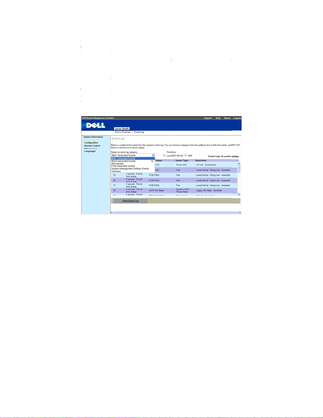
vent Log
he System E
anaged syst
ontroller (B
nformation a
ype and a sho
Select
Server
nformation.
he list can b
ategories, B
enerated Ev
select. Subseq
ent Log (SEL
m. The SEL i
C) or BIOS o
out system ev
t description.
ealth
in me
sorted by
C Generated
nts, System
ent selects Ti
sele
page display
generated by
the manage
nts: event ID,
u bar. Click
cting any eve
vents, BIOS
anagement So
e Zone. Ther
system event
he Baseboard
system. The
time stamp, s
E
ent Log
t log categor
enerated Eve
tware Events,
are two opti
that occur on
Management
EL lists the fo
nsor name, se
to vi
w specific ev
. There are si
ts, SMI Hand
and Unknow
ns, Local and
the
llowing
sor
nt
ler, FCB
you can
GMT.
lick
Clear E
ent Log
to C
ear the SEL.
U
ing the WEB UI
| 11
Page 12

A
WcTaT
r
C
l
n
e
s
n
m
y
d
e
c
m
r
i
o
m
w
i
d
a
e
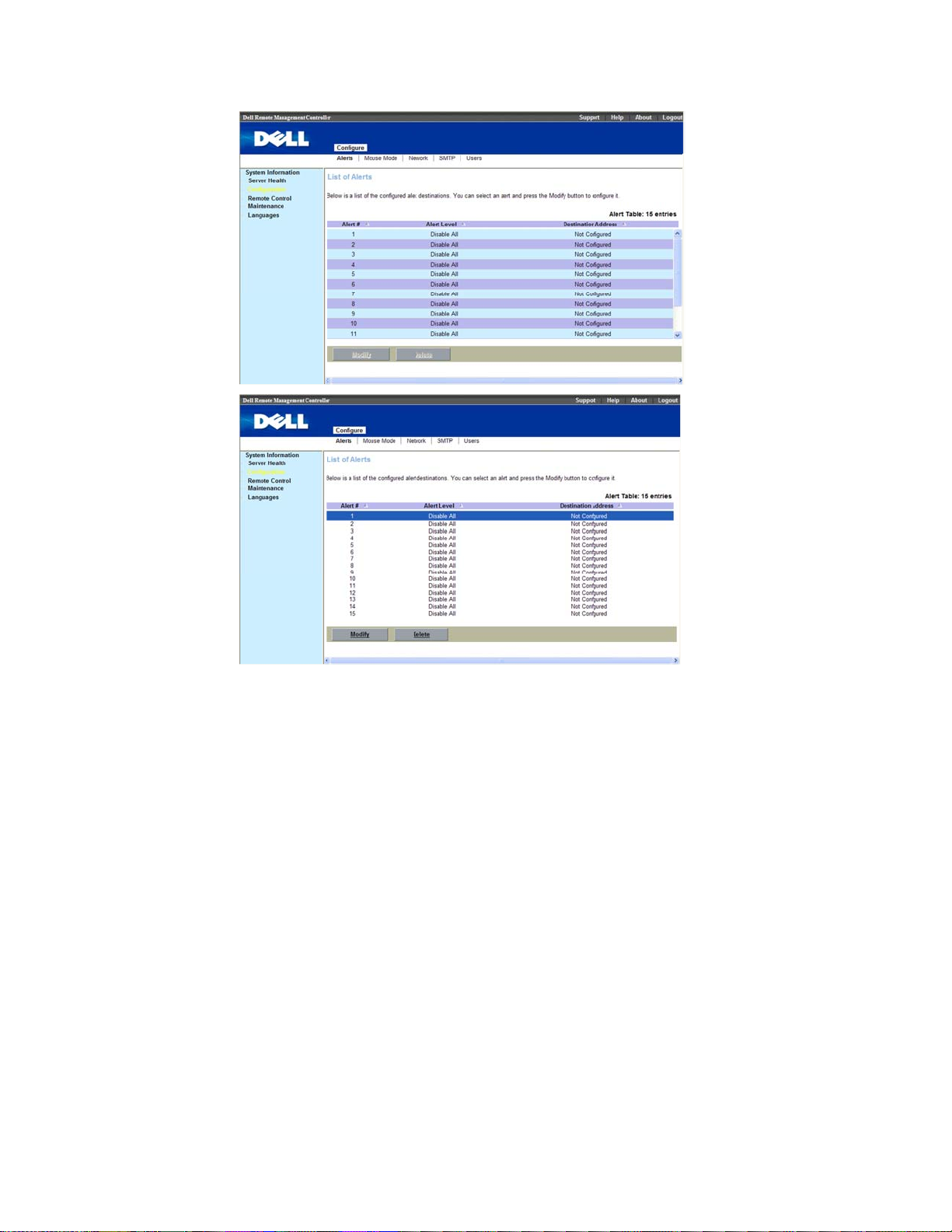
Configu
lerts
hen the BM
omponent fai
he
Alerts
ctivate the al
o set up a de
1
wi
Click a
ation
senses a plat
ure, an alert
dow enables
rts for each a
tination to rec
Alert Numb
form event, su
essage can be
ou to enter e
dress.
ive alerts, pe
er
, click
Mod
h as an envir
sent to one or
ail addresses,
form the follo
fy
.
nmental warn
ore email ad
IP addresses,
ing procedur
ng or a
resses.
nd to
Using the WEB UI
| 12
Page 13
Using the WEB UI | 13
Page 14
A
E
a
e
y
n
t
i
d
p
r
a
a
p
l
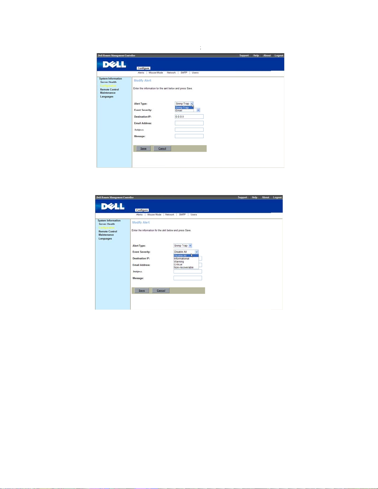
2
Select
lert Type
, th
re are two op
ions,
Snmp T
ap and Emai
.
3
Select
Inform
4
If your
Using the WEB UI
vent Severit
tional, Warni
Alert Type
| 14
, The five opt
g, Critical an
is
Snmp Trap, ty
ons available
Non-recover
e the destinat
re, Disable Al
ble.
ion IP.
l,
Page 15

b
o
h
j
s
e
a
a
5
If your
enter a
Alert Type
rief descripti
is
Email, enter t
n for the
e destination
Sub
ect
of the em
mail address,
il.
nd
6
Click
S
ave
.
U
ing the WEB UI
| 15
Page 16

M
I
m
ARN
D
t
e
m
A
t
s
t
e
s
w
O
I
K
m
c
ouse mode
t is an option
ode depends
bsolute
elative
mod
mod
o set up mous
on OS can ge
e for host’s sy
for host’s sys
e mode which
accurate mou
tem is Windo
em is Linux
will using in
e pointer.
s OS
S.
VM. Setting
ouse
etwork
Show the Re
HCP or ST
Using the WEB UI
ote Managem
TIC IP then cl
| 16
nt Controller
ck “
Save
”.
P address info
rmation. You
an set
Page 17

c
M
n
s
t
e
SMTP
Set E-mail (S
lick “
Save
TP) server IP address for se
”.
ding alert no
ification to us
r then
U
ing the WEB UI
| 17
Page 18

U
Tua
TTTUT
g
n
i
p
t
v
e
s
t
w
u
m
R
n
n
q
l
g
s
m
A
f
g
.
r
D
t
g
n
i
r
i
a
d
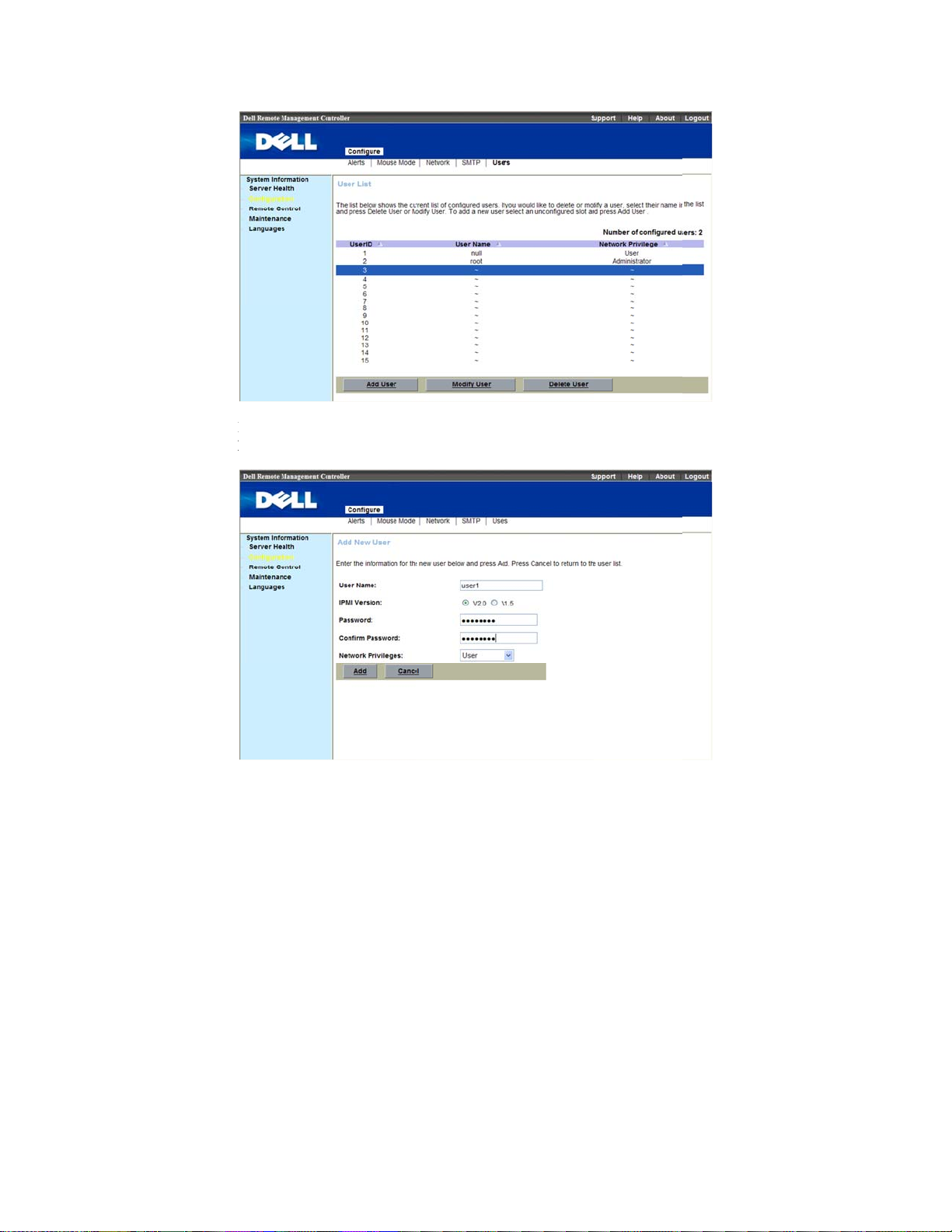
sers
he
Users pa
sers. You ca
ccessing priv
able 1-28 dis
able Error! No
e enables you
control user
leges.
lays the
text of specified
User
o view infor
ho can login
s
list for existi
style in docume
ation and con
emote Mana
g BMC users
t.-3. BMC Use
igure existing
ement Control
Information
BMC
ler and
BMC Informa
User ID
User Name
Network Pri
here are thre
ser.
o add new u
ion
ilege
operations in
er, click their
Description
Displays a se
Displays the
Displays the
the user is as
User, Custo
Users
page:
ser ID numb
uential user I
ogin name of
roup (privile
igned. (Admi
, or None).
dd User, Mod
r
, in the
Use
number.
he user.
e level) to wh
istrator, Oper
fy User and D
s
list. Click
A
ch
tor,
elete
d User
.
Using the WEB UI
| 18
Page 19
E
p
m
c
o
c
s
o
r
nter user na
rivileges, cli
e, IPMI versi
k
Add
.
n, password,
onfirm passw
rd and netwo
U
ing the WEB UI
k
| 19
Page 20

TCMpTUr
U
a
c
g
N
o
u
s
i
c
h
t
r
d
m
l
e
b
w
s
n
o
e
w
l
e
o change the
lick
Modify
odify user n
rivileges, cli
o delete new
ser
. A dialo
efresh page.
settings for a
ser
.
me, IPMI ver
k
Modify
user, click the
box appears
.
ser, click thei
ion, passwor
r
user ID nu
,
lick
yes
user ID num
, confirm pass
ber
to de
ete the user a
, in the
er
, in the
ord and net
U
ers
list. Click
d automatical
Us
rs
list.
ork
Delete
y
Using the WEB UI
OTE:
You must
therwise these op
| 20
ave Configure Us
ions are not availa
rs permission to c
le
nfigure a BMC us
r;
Page 21

PTC
T
C
o
n
s
e
m
y
w
d
y
i
l
-
o
e
n
s
t
n
t
s
r
o
a
n
o
n
y
w
w
Remote
ower Contr
his feature e
and reset
Select
Control Oper
able Error! No
the
Remot
ontrol
l
ables the adm
ystem remote
Control
ation
text of specified
in m
. Table 1
nistrator to
y.
enu bar. Click
4 list the pow
style in docume
p
wer on, powe
Power Contr
r control oper
t.-4. Power Co
off, power c
l.
Select a
tion;
trol Operation
Po
cle,
er
Options
Power Contro
Reset Syste
Power Off S
Immediate
Soft Shutdo
Orderly Shut
Power On S
Power Cycle
l Operation
stem –
n –
own
stem
System
Description
Reboots sy
boot).
Powers off
Shuts dow
Powers on
Powers off,
boot).
tem without p
he system.
system.
he system.
then power o
wering off (
system (cold
U
ing the WEB UI
arm
| 21
Page 22

CCTkocTta
n
m
r
R
h
a
c
N
hlaVNNcth
m
e
h
a
a
pa
e
m
e
e
s
m
8
c
f
c
y
e
u
t
a
s
e
t
e
s
d
w
t
p
r
e
t
s
n
c
C
s
y
n
n
d
e
5
o
e
o
u
lick
Perfor
Action
to en
ble the select
d
Power Con
rol Operatio
.
Console Redi
he
Console
eyboard on t
n a remote m
onsole redire
he most pow
o redirect the
bility to man
ot.
Using the WEB UI
ection
edirection
e local manag
naged system
tion sessions.
OTE:
Before you
ave the Java runti
ter installed on th
iewer is not install
OTE:
Sometime
OTE:
The recom
lient) is at least 12
e console in full s
inimum.
rful feature o
ost system’s
ge your host s
| 22
ge enables yo
ment station
. You can run
can use the conso
e environment in
host system. If th
d, you are promp
the Console is ref
ended display re
0 x 1024 pixels at
reen mode if your
your Remote
onsole. To re
stem as if it
to use the dis
o control the c
maximum of
le redirection featu
talled. This featur
BMC detects tha
ed to install it.
rred to as the Se
olution on the ma
60 Hz with 32 bit
monitor resolution
Management
irect the host
ere physicall
lay, mouse, a
orresponding
four simultan
e, your browser m
needs Java 1.5.1
the Java Video
sion Viewer.
agement station (
lor. You cannot vi
is less than this
ontroller is th
ystem’s cons
in front of yo
d
evices
ous
ust
or
r
ew
e ability
le is the
, but
Page 23

C
BII
T
r
e
S
S
m
i
g
i
o
e
e
t
s
M
o
s
E
L
o
Console Redi
efore you us
f the host’s O
f the host’s O
his menu ite
system.
1
Cl
ection Confi
Console Red
is Linux, ple
is Windows,
allows you t
ck
Console R
uration
rection, pleas
se change the
please change
start a Remo
direction
.
check your
Mouse mode
the
Mouse m
e Console ses
ouse mode
to
RELATIV
de
to
ABSO
ion with the h
.
E
UTE
st
U
ing the WEB UI
| 23
Page 24

a
2
Click
J
va Console
.
3
And cli
Using the WEB UI
Mouse
ck
| 24
item to
Sync Cursor
.
Page 25

B
Tmb
wTd
v
e
n
e
m
NdNCv
u
e
t
i
m
h
n
g
a
o
p
c
l
f
d
s
e
d
p
p
s
e
d
a
t
y
d
D
MC Virtual
he
Device
edia enables
e available o
ere present o
he
Device
rive, or ISO i
irtualized.
Media
m
nu allows yo
a floppy imag
the managed
n the local sys
m
nu in KVM d
age on
OTE:
You must
isconnect a drive.
OTE:
You can e
D/DVD drive/ima
irtualized at a time
to virtualize
, floppy drive
system's cons
em.
splays the flo
the
anagement
ave Access Virtua
able virtual media
e. Only one drive/i
A USB key/flash
diskette imag
or CD/DVD
le as if the flo
py image, flo
onsole that i
Media permission
or one floppy/driv
age for each me
rive is treated as
U
or drive. Vir
rive on your s
py image or
py drive, CD/
currently
to virtualize or
image and one
ia type can be
floppy drive.
ing the WEB UI
ual
stem to
rive
VD
| 25
Page 26

V
T
wtc
iMYcr
D
i
i
d
d
d
i
t
a
c
h
c
o
a
D
o
h
e
h
i
e
m
D
r
e
h
u
h
O
h
u
t
d
M
w
irtualizing
he
Device
cl
indow. To v
he table. The
heckbox. An
mage is adde
evices
ent displays t
rtualize a devi
evice maps t
then select th
to the list of
e list of devic
e, select the c
the server at t
e image file w
vailable devic
s available fo
eckbox in th
is point. To
th the dialog t
s.
mapping in t
Mapped
nmap, deselec
at is displaye
col
e main
mn of
the
. The
apping a V
ou can selec
heck box for
ead only whi
Using the WEB UI
rtual Media
a drive to bec
particular dri
h cannot be c
| 26
rive
me a virtual
ve. CD/DVD
anged.
edia drive by
rives and IS
selecting the
images are al
apped
ays
Page 27

U
T
d
c
r
e
t
N
sle
i
i
i
e
a
m
M
o
m
e
t
x
n
s
k
h
t
d
i
m
nmapping a
o unmap a vi
rive. Becaus
onfirm the ac
Virtual Med
tual media dr
some interact
ion before the
OTE:
The assign
pecial file (Red H
tter on this syste
a Drive
ve, select the
on might be g
drive is unm
d virtual drive lett
®
Enterprise Linu
(management co
apped
chec
ing on with t
apped.
r (Microsof
®
sole).
®
) may not be the
box for a part
e drive, you
Win
ows®) or device
same as the drive
U
ing the WEB UI
icular
ust
| 27
Page 28

B
T
t
MCV
T
M
e
n
l
e
t
t
m
s
d
R
o
n
n
i
i
i
i
d
u
o
e
o
e
e
e
e
e
u
s
s
b
R
e
n
s
e
MC KVM
he BMC KV
o provide acc
ouse, Optio
Control
tag, c
ideo
client main
ss to function
s, Device
ick
, an
Console
enu consists
available thr
Help
. To lau
edirection
.
of five menu
ugh the view
ch a KVM se
ptions, which
r:
Video, Key
ssion, select
are used
oard
,
emote
able Error! No
Dropdown M
Start Redirec
Stop Redirec
Restart
Full Screen
Exit
Using the WEB UI
text of specified
nu Items
ion
ion
| 28
style in docume
Description
This menu
Redirection
This menu
Redirection
This menu
Redirection
Redirection
This menu
Console Re
NOTE: Set yo
x 768 so that y
screen.
Exit consol
t.-5. BMC KVM
tem can be us
.
tem can be us
.
tem can be us
and then start
again.
tem can be us
irection in F
r client system’s
u can view the ho
redirection.
Video Menu It
d to begin Co
d to halt Cons
d to stop Con
Console
d to view the
ll Screen mod
creen resolution to
t system in true fu
ms
sole
ole
ole
.
1024
ll
Page 29

K
T
e
C
A
T
L
w
n
e
>
e
k
e
>
e
k
e
O
e
b
l
s
d
C
d
o
d
C
d
o
d
r
l
n
i
i
e
e
l
s
eyboard
able Error! No
Dropdown M
Hold Right
Hold Right
Hold Left C
Hold Left A
Left Windo
text of specified
nu Items
TRL Key
LT Key
RL Key
T Key
s Key
style in docume
Description
This menu it
side <CTRL
Redirection.
This menu it
side <ALT>
This menu it
side <CTRL
Redirection.
This menu it
side <ALT>
This menu it
side <WIND
Redirection s
e performed
Hold Down
Press and Re
t.-6. BMC KVM
m can be use
key when in
m can be use
ey when in C
m can be use
key when in
m can be use
ey when in C
m can be use
WS> key du
ssion. The fo
:
ease
Keyboard me
to act as the r
onsole
to act as the r
nsole Redirec
to act as the l
onsole
to act as the l
nsole Redirec
to access the
ing a Console
lowing action
U
ing the WEB UI
u items
ght-
ght-
tion.
ft-
ft-
tion.
eft-
can
| 29
Page 30

M
L
e
w
+
r
o
r
e
W
e
b
l
e
m
e
-
d
e
l
d
L
o
y
w
n
s
u
L
t
e
u
Dropdown M
Right Windo
ALT+CTRL
Full Keyboa
ouse
nu Items
s Key
DEL
d
Description
This menu it
right-side <
Redirection s
e performed
Hold Down
Press and Re
This menu it
depressed the
keys down si
that you are r
User can key
Ctrl+C
m can be use
INDOWS> k
ssion. The fo
:
ease
m can be use
<CTRL>, <A
ultaneously
directing.
in function ke
to access the
y during a Co
lowing action
to act as if yo
T> and <DE
n the host sys
. For exampl
sole
can
>
em
:
Sync Cursor f
Single Cursor:
SI 8708EM2
Using the WEB UI
r remote cont
To solve prob
WebBIOS.
| 30
ol mouse.
lem of remote
mouse can’t
ork correctly
nder
Page 31

O
B
V
D
T
e
s
e
R
e
u
u
n
M
s
p
c
m
e
n
Options
andwidth: H
ideo Setting
evice
able Error! No
Dropdown M
Redirect CD
lps in regulat
: Helps in adj
text of specified
nu Items
OM
d the network
st video resol
style in docume
Description
Enable you
the CD-RO
ROM drive
bandwidth.
tion.
t.-7. BMC KVM
to start or sto
drive. You
from client co
Device Menu t
the redirectio
an choose the
puter.
U
ing the WEB UI
ms
of
CD-
| 31
Page 32

Dropdown Menu Items Description
Redirect ISO Enable you to start or stop the redirection of
the ISO. You can choose the CD IMAGE file
from client computer.
Redirect Floppy / USB Enable you to start or stop the redirection of
the Floppy/USB drive. You can choose the
Floppy/USB drive from client computer.
Redirect Floppy Image Enable you to start or stop the redirection of
the floppy drive. You can choose the Floppy
IMAGE file from client computer.
Maintenance
Firmware Update
Use the Firmware Update feature to upgrade to the latest firmware version. The
following data is included in the BMC firmware package:
Compiled BMC firmware code and data
Web-based user interface, JPEG, and other user interface data files
Default configuration files
NOTE:
Updating the BMC Firmware
NOTE:
version and save it on your local system. During the process of firmware
update, the AC power of the managed system cannot be unplugged and the
Web GUI cannot be closed.
1
Select “
Using the WEB UI | 32
The firmware update retains the current BMC settings.
Before beginning the firmware update, download the latest firmware
Maintenance
” in menu bar. Click
Enter Update Mode
Page 33

e
i
x
\
a
o
l
o
tnum
U
a
p
p
r
d
i
a
a
o
r
e
a
s
n
o
a
u
o
e
e
u
a
s
2
Brows
3
4
file res
E
C:
Select t
Norm
N
va
F
wi
Click
to, or Type th
des.
ample:
<Product N
e
Update Ty
l
).
rmal:
idates the ta
rced:
hout validat
ber.
pload Firmw
An u
Force
e path on your
me>\KCSFl
e
as
Normal
date operati
get board, ta
update mak
ng target bo
re
.
system where
sh\<image_
or
Forced
(Th
n will occur
get product
s the BMC
rd, target pr
the firmware i
ame>
e default valu
nly when th
nd version n
pdate the im
duct and ver
mage
is
BMC
mber.
ge
ion
U
ing the WEB UI
| 33
Page 34

r
e
t
d
C
P
x
o
f
n
f
e
i
r
5
A wind
6
7
Compa
Select t
(The d
Click
ow, telling tha
e the uploade
e
Preserve
fault value is
S
art Upgrade
the firmware
image with e
onfiguration
reserve Con
.
image has bee
isting device
r Don’t Pres
iguration
).
verified, app
irmware vers
rve Configu
ears.
on.
ation
Using the WEB UI
| 34
Page 35

T
g
d
a
t
s
s
t
he update mi
8
The up
ht take sever
ate is comple
l minutes.
ed. Close the
ession and au
omatically log
U
ing the WEB UI
out.
| 35
Page 36

h
9
After t
e BMC resets, click
Log In to log in to the BMC again.
Using the WEB UI
| 36
Page 37

V
3
Sensors Threshold
Table Error! No text of specified style in document.-8. Sensors Threshold
Sensor
Number
Fan
01h
02h
03h
04h
oltage
14h PS 12V
15h PS 5V
16h
17h PS 3.3V
18h PS 1.2V Actual_Reading (Volts) = Raw_Data x 0.0087
Sensor
Name
FCB
FAN1
FCB
FAN2
FCB
FAN3
FCB
FAN4
Standby
3.3V
The Converting Formula
Upper nonrecoverable
Actual_Reading (RPM) = Raw_Data x 100
0xFF 0xFF 0xFF 0x00 0x0F 0x00
Actual_Reading (RPM) = Raw_Data x 100
0xFF 0xFF 0xFF 0x00 0x0F 0x00
Actual_Reading (RPM) = Raw_Data x 100
0xFF 0xFF 0xFF 0x00 0x0F 0x00
Actual_Reading (RPM) = Raw_Data x 100
0xFF 0xFF 0xFF 0x00 0x0F 0x00
Actual_Reading (Volts) = Raw_Data x 0.062
0xD8 0xD4 0xCF 0xAB 0xAF 0xB4
Actual_Reading (Volts) = Raw_Data x 0.026
0xD7 0xD3 0xCD 0xA9 0xAE 0xB3
Actual_Reading (Volts) = Raw_Data x 0.0172
0xD6 0xD3 0xCD 0xA9 0xAD 0xB3
Actual_Reading (Volts) = Raw_Data x 0.026
0xFF 0xFF 0xFF 0x00 0x00 0x00
Upper
critical
Upper
noncritical
Lower nonrecoverable
Lower
critical
Lower
noncritical
Sensors Threshold | 37
Page 38

Sensor
Number
Sensor
Name
The Converting Formula
Upper nonrecoverable
0x98 0x96 0x92 0x7D 0x7F 0x84
19h PS 1.1V
51h
52h
53h
54h
Temperature
VCORE
1
VCORE
2
VCORE
3
VCORE
4
MLB
21h
TEMP
1
MLB
22h
TEMP
2
MLB
23h
TEMP
3
MLB
24h
TEMP
4
25h
26h
NB1_T
EMP
NB2_T
EMP
Actual_Reading (Volts) = Raw_Data x 0.0087
0xFF 0xFF 0xFF 0x00 0x00 0x00
Actual_Reading (Volts) = Raw_Data x 0.0083
0x64 0x62 0x5F 0x00 0x00 0x00
Actual_Reading (Volts) = Raw_Data x 0.0116
0x70 0x6E 0x6B 0x00 0x00 0x00
Actual_Reading (Volts) = Raw_Data x 0.0083
0x64 0x62 0x5F 0x00 0x00 0x00
Actual_Reading (Volts) = Raw_Data x 0.0116
0x70 0x6E 0x6B 0x00 0x00 0x00
Actual_Reading (degrees C) = Raw_Data
0x55 0x50 0x4B 0x00 0x00 0x00
Actual_Reading (degrees C) = Raw_Data
0x55 0x50 0x4B 0x00 0x00 0x00
Actual_Reading (degrees C) = Raw_Data
0x55 0x50 0x4B 0x00 0x00 0x00
Actual_Reading (degrees C) = Raw_Data
0x55 0x50 0x4B 0x00 0x00 0x00
Actual_Reading (degrees C) = Raw_Data
0x77 0x75 0x73 0x00 0x00 0x00
Actual_Reading (degrees C) = Raw_Data
0x77 0x75 0x73 0x00 0x00 0x00
Upper
critical
Upper
noncritical
Lower nonrecoverable
Lower
critical
Lower
noncritical
Sensors Threshold | 38
Page 39

Sensor
Number
61h
62h
63h
64h
2Ah
E0h-FFh
Power Supply
Sensor
Name
CPU1_
Temp
CPU2_
Temp
CPU3_
Temp
CPU4_
Temp
FCB
Ambien
t1
DIMM_
A1 to
DIMM_
D8
The Converting Formula
Upper nonrecoverable
Actual_Reading (
Upper
critical
℃
Upper
noncritical
) = Raw_Data
Lower nonrecoverable
Lower
critical
Lower
noncritical
0x4E 0x4C 0x4B 0x00 0x00 0x00
℃
Actual_Reading (
) = Raw_Data
0x4E 0x4C 0x4B 0x00 0x00 0x00
℃
Actual_Reading (
) = Raw_Data
0x4E 0x4C 0x4B 0x00 0x00 0x00
℃
Actual_Reading (
) = Raw_Data
0x4E 0x4C 0x4B 0x00 0x00 0x00
Actual_Reading (degrees C) = Raw_Data (only support Sensor
Reading, threshold unsupport)
0xFF 0x32 0x00 0x00 0x00 0x00
℃
Actual_Reading (
0x63 0x61 0x5F
) = Raw_Data
0x00 0x00 0x00
A1h
A3h
A4h
MB_12
V_Curr
ent
PSU 1
POUT
PSU 2
POUT
Actual_Reading = Raw_Data
0xFF 0xFF 0xFF
0x00 0x00 0x00
Actual_Reading = Raw_Data
0xFF 0xFF 0xFF 0x00 0x00 0x00
Actual_Reading = Raw_Data
0xFF 0xFF 0xFF 0x00 0x00 0x00
Sensors Threshold | 39
Page 40

Events Table
Table Error! No text of specified style in document.-9. Threshold Sensors Event
4
Sensor
Number
01h FCB FAN1
02h FCB FAN2
03h FCB FAN3
04h FCB FAN4
21h MLB TEMP 1
22h MLB TEMP 2
23h MLB TEMP3
24h MLB TEMP4
25h NB1_TEMP
26h NB2_TEMP
61h CPU1_TEMP
62h CPU2_TEMP
63h CPU3_TEMP
64h CPU4_TEMP
E0h-E7h DIMM_A1-8
E8h-EFh DIMM_B1-8
F0h-F7h DIMM_C1-8
F8h-FFh DIMM_D1-8
Sensor Name Sensor Type Events
04h(Fan)
01h
(Temperature)
Lower Critical – going low
asserted
Lower Critical – going low
deasserted
Upper Non-critical – going
high asserted
Upper Non-critical – going
high deasserted
Upper Critical – going high
asserted
Upper Critical – going high
deasserted
Upper Non-recoverable –
going high asserted
Upper Non-recoverable –
going high deasserted
Events Table | 40
Page 41

Sensor
Number
2Ah
Sensor Name Sensor Type Events
FCB
Ambient1
14h PS 12V
15h PS 5V
16h STBY 3.3V
01h
(Temperature)
02h
(Voltage)
Upper Critical – going high
asserted
Upper Critical – going high
deasserted
Upper Non-recoverable –
going high asserted
Upper Non-recoverable –
going high deasserted
Upper Non-critical – going
high asserted
Upper Non-critical – going
high deasserted
Upper Critical – going high
asserted
Upper Critical – going high
deasserted
Upper Non-recoverable –
going high asserted
Upper Non-recoverable –
going high deasserted
Lower Non-critical – going
low asserted
Lower Non-critical – going
low deasserted
Lower Critical – going low
asserted
Lower Critical – going low
deasserted
Lower Non-recoverable –
going low asserted
Lower Non-recoverable –
going low deasserted
Events Table | 41
Page 42

Table Error! No text of specified style in document.-10. Non-threshold Sensors Event
Table
Sensor
Number
Sensor Name
Sensor
Type
SensorSpecific
Offset
Events
71h PEF Action 12h O4h PEF Action
23h 00h Timer expired, status only
01h Hard Reset
72h WatchDog2
02h Power Down
03h Power Cycle
08h Timer Interrupt
74h AC Pwr On 09h 04h AC lost deasserted
73h ACPI Pwr
State
22h 0Bh Legacy ON state
0Ch Legacy OFF state
41h CPU1Status
42h CPU2Status
43h CPU3Status
07h 01h Thermal Trip
44h CPU4Status
40h SEL Fullness 10h 02h Log Area Reset/Cleared
04h SEL Full
05h SEL Almost Full
A5h PCI Bus 13h 04h PCI PERR
05h PCI SERR
Events Table | 42
Page 43

Sensor
Number
Sensor Name
Sensor
Type
SensorSpecific
Offset
Events
60h Memory 0Ch 00h Correctable ECC/other
correctable memory error
01h Uncorrectable ECC/other
uncorrectable memory
error
05h Correctable ECC/other
correctable memory error
logging limit reached
75h Security 06h 05h Out-of-band Access
Password Violation
AAh PwrLimitAlert 07h 05h DCMI Power management
exception action
Events Table | 43
Page 44

/
5
IPMI 1.5 / 2.0 Command Support
List
Table Error! No text of specified style in document.-11. IPMI Device Global Commands
Command NetFn CMD O
Get Device ID App 01h M Yes
Cold Reset
Warm Reset
Get Self Test Results
Manufacture Test On
Set ACPI Power State
Get ACPI Power State
Get Device GUID
Broadcast Commands:
Broadcast ‘Get Device ID’ App 01h O No
Table Error! No text of specified style in document.-12. BMC Device and Messaging
Commands
Command NetFn CMD O/M Supported
Set BMC Global Enables App 2Eh M Yes
Get BMC Global Enables App 2Fh M Yes
Clear Message Buffer Flags App 30h M Yes
Get Message Buffer Flags App 31h M Yes
Enable Message Channel Receive App 32h O Yes
Get Message
App 02h O Yes
App 03h O No
App 04h M Yes
App 05h O Yes
App 06h O Yes
App 07h O Yes
App 08h O Yes
App 33h M Yes
M Supported
IPMI 1.5 / 2.0 Command Support List | 44
Page 45

Command NetFn CMD O/M Supported
Send Message
Read Event Message Buffer App 35h O Yes
Get BT Interface Capabilities App 36h O No
Get System GUID
Get Channel Authentication
Capabilities
Get Session Challenge
Activate Session Command App 3Ah O Yes
Set Session Privilege Level
Command
Close Session
Get Session Information App 3Dh O Yes
Get Authentication Code Command App 3Fh O Yes
Set Channel Access Commands App 40h O Yes
Get Channel Access Commands App 41h O Yes
Get Channel Info Command App 42h O Yes
Set User Access Commands App 43h O Yes
Get User Access Commands App 44h O Yes
Set User Name Commands App 45h O Yes
Get User Name Commands App 46h O Yes
Set User Password Commands App 47h O Yes
Active Payload Command App 48h O Yes
Deactivate Payload Command App 49h O Yes
Get Payload Activation Status App 4Ah O Yes
Get Payload Instance Info Command App 4Bh O Yes
Set User Payload Access App 4Ch O Yes
Get User Payload Access App 4Eh O Yes
Get Channel Payload Support App 4Fh O Yes
Get Channel Payload Version App 50h O Yes
App 34h M Yes
App 37h O Yes
App 38h O Yes
App 39h O Yes
App 3Bh O Yes
App 3Ch O Yes
IPMI 1.5 / 2.0 Command Support List | 45
Page 46

Command NetFn CMD O/M Supported
Master Write-Read I2C App 52h M Yes
Get Channel Cipher Suites App 54h O Yes
Suspend/Resume Payload Encryption App 55h O Yes
Set Channel Security Keys App 56h O Yes
Get System Interface Capabilities App 57h O Yes
Set System Info Parameters App 58h O Yes
Get System Info Parameters App 59h O Yes
Table Error! No text of specified style in document.-13. BMC Watchdog Timer
Commands
Command NetFn CMD O/M Supported
Reset Watchdog Timer
Set Watchdog Timer
Get Watchdog Timer
Table Error! No text of specified style in document.-14. Chassis Commands
Command NetFn CMD O/M Supported
Get Chassis Capabilities Chassis 00h M Yes
Get Chassis Status
Chassis Control
Chassis Reset
Chassis Identify
Set Chassis Capabilities Chassis 05h O No
Set Power Restore Policy Chassis 06h O Yes
Get System Reset Cause (Note:
RESTART CAUSE [3:0] AH=
SOFT RESET (E.G. CTRL-ALTDEL) -UNSUPPORT.
IPMI 1.5 / 2.0 Command Support List | 46
App 22h M Yes
App 24h M Yes
App 25h M Yes
Chassis 01h M Yes
Chassis 02h M Yes
Chassis 03h O No
Chassis 04h O Yes
Chassis 07h O Yes
Page 47

Set System Boot Options (Note:
PARAMETER #5 DATA3 [6:5]FIRMWARE VERBOSITY - BIOS
UNSUPPORT
PARAMETER #7 UNSUPPORT
Get System Boot Options (Note:
PARAMETER #7 UNSUPPORT
Set Front Panel Button Enable Chassis 0Ah O No
Set Power Cycle Interval Chassis 0Bh O Yes
Get POH Counter
Table Error! No text of specified style in document.-15. Event Commands
Command NetFn CMD O/M Supported
Set Event Receiver
Get Event Receiver
Platform Event
Table Error! No text of specified style in document.-16. SEL Commands
Command NetFn CMD O/M Supported
Get SEL Info
Get SEL Allocation Info Storage 41h O Yes
Reserve SEL
Get SEL Entry
Add SEL Entry
Partial Add SEL Entry
Delete SEL Entry
Clear SEL
Get SEL Time
Set SEL Time
Chassis 08h O Yes
Chassis 09h O Yes
Chassis 0Fh O Yes
S/E 00h O Yes
S/E 01h O Yes
S/E 02h M Yes
Storage 40h M Yes
Storage 42h O Yes
Storage 43h M Yes
Storage 44h M Yes
Storage 45h O No
Storage 46h O Yes
Storage 47h M Yes
Storage 48h M Yes
Storage 49h M Yes
IPMI 1.5 / 2.0 Command Support List | 47
Page 48

Get Auxiliary Log Status Storage 5Ah O No
Set Auxiliary Log Status Storage 5Bh O No
Get SEL Time UTC Offset Storage 5Ch O Yes
Set SEL Time UTC Offset Storage 5Dh O Yes
NOTE:
Table Error! No text of specified style in document.-17. SDR Repository Commands
Command NetFn CMD O/M Supported
Get SDR Repository Info Storage 20h M Yes
Get SDR Repository Allocation Info Storage 21h O Yes
Reserve SDR Repository Storage 22h M Yes
Get SDR
Add SDR
Partial ADD SDR
Delete SDR
Clear SDR Repository
Get SDR Repository Time Storage 28h O Yes
Set SDR Repository Time Storage 29h O No
Enter SDR Repository Update Mode Storage 2Ah O Yes
Exit SDR Repository Update Mode Storage 2Bh O Yes
Run Initialization Agent Storage 2Ch O Yes
Table Error! No text of specified style in document.-18. FRU Inventory Device
Commands
Support for Partial Add SEL is not required when Add SEL is
supported.
Storage 23h M Yes
Storage 24h M Yes
Storage 25h O Yes
Storage 26h O No
Storage 27h M Yes
Command NetFn CMD O/M Supported
Get FRU Inventory Area Info Storage 10h M Yes
Read FRU Inventory Data Storage 11h M Yes
IPMI 1.5 / 2.0 Command Support List | 48
Page 49

Write FRU Inventory Data Storage 12h M Yes
IPMI 1.5 / 2.0 Command Support List | 49
Page 50

Table Error! No text of specified style in document.-19. Sensory Device Commands
Command NetFn CMD O/M Supported
Get Device SDR Info
Get Device SDR
Reserve Device SDR Repository S/E 22h M No
Get Sensor Reading Factors S/E 23h M Yes
Set Sensor Hysteresis
Get Sensor Hysteresis
Set Sensor Threshold
Get Sensor Threshold
Set Sensor Event Enable S/E 28h M Yes
Get Sensor Event Enable S/E 29h M Yes
Re-arm Sensor Events
Get Sensor Event Status S/E 2Bh M No
Get Sensor Reading
Set Sensor Type
Get Sensor Type
Set Sensor Reading and Event Status S/E 2Fh O No
Set Sensor Reading and Event Status
(
Note:
ONLY FOR FAN DEVICES.)
Table Error! No text of specified style in document.-20. LAN Commands
Command NetFn CMD O/M Supported
S/E 20h M No
S/E 21h M No
S/E 24h M Yes
S/E 25h M Yes
S/E 26h M Yes
S/E 27h M Yes
S/E 2Ah M No
S/E 2Ch M Yes
S/E 2Dh M Yes
S/E 2Eh M No
S/E 30h O Yes
Set LAN Configuration Parameters
(
Note:
Parameter 9 and 25 are not support ed.)
Get LAN Configuration Parameters
(
Note:
Parameter 9 and 25 are not support ed.)
Suspend BMC ARP
Get IP/UDP/RMCP Statistics Transport 04h O No
IPMI 1.5 / 2.0 Command Support List | 50
Transport 01h M Yes
Transport 02h M Yes
Transport 03h O Yes
Page 51

Table Error! No text of specified style in document.-21. PEF/PET Alerting Commands
Command NetFn CMD O/M Supported
Get PEF Capabilities
Arm PEF Postpone Timer S/E 11h M Yes
Set PEF Configuration Parameters S/E 12h M Yes
Get PEF Configuration Parameters S/E 13h M Yes
Set Last Processed Event ID S/E 14h M Yes
Get Last Processed Event ID S/E 15h M Yes
Alert Immediate
PET Acknowledge
Table Error! No text of specified style in document.-22. SOL Commands
Command NetFn CMD O/M Supported
SOL Activating
Set SOL Configuration Parameters S/E 21h O Yes
Set SOL Configuration Parameters S/E 22h O Yes
S/E 10h M Yes
S/E 16h O Yes
S/E 17h O Yes
Transport 20h O Yes
IPMI 1.5 / 2.0 Command Support List | 51
Page 52

6
IPMI OEM Command List
Table Error! No text of specified style in document.-23. OEM1 Commands (NetFn 30H,
31H)
Command NetFN cmd Format
Reserved
Extended
Configuration
OEM1 01H
Request:
Response:
Byte 1 – completion code
Byte 2 - Reservation ID
IPMI OEM Command List | 52
Page 53

Command NetFN cmd Format
Get Extended
Configuration
OEM1 02H
Request:
Byte 1 - Reservation ID
Byte 2 - Configuration ID
Byte 3 - Attribute ID. 00h means read entire
configuration data.
Byte 4 - Index (used by table object only)
Byte 5 - Data Offset – LSB
Byte 6 - Data Offset – MSB
Byte 7 - Bytes to read. FFh means read entire
configuration or attribute.
Response:
Byte 1 – Completion code (01h:no more
data)
Byte 2 – Configuration ID
Byte 3 – Attribute ID
Byte 4 – Index (valid only for table object
only)
Byte 5 – Number of bytes returned, 1-based
Byte 6~N – Data
(Please check with table 1-25 Extended
Configuration)
IPMI OEM Command List | 53
Page 54

Command NetFN cmd Format
Set Extended
Configuration
OEM1 03H
Request:
Byte 1 - Reservation ID
Byte 2 - Configuration ID
Byte 3 - Attribute ID. 00h means read entire
configuration data.
Byte 4 - Index (used by table object only)
Byte 5 - Data Offset – LSB
Byte 6 - Data Offset – MSB
Byte 7 - In progress
[7:4] reserved
[3:0] in progress
0 – in progress
1 – last configuration data being transferred
in this request
Byte 8~N – Data to be written.
Response:
Byte 1 – Completion code (01h:no more
data)
(Please check with table 1-25 Extended
Configuration)
IPMI OEM Command List | 54
Page 55

Command NetFN cmd Format
Restore to
defaults
OEM1 04H
Request:
Byte 1 -Configuration to be restored to
defaults:
[7:5] 111b= Restore the remaining
parameters not included in below lists.
000b= Remaining parameters stay what it is.
All other values are reserved
[4] 1b= Restore PEFs to defaults
[3] 1b= Restore serial configuration
parameters to defaults
[2] 1b= Restore SOL configuration
parameters to defaults
[1] 1b= Restore LAN configuration
parameters to defaults
[0] 1b= Restore user accounts to defaults
Response:
Byte 1 –Completion Code
CCh = restore to one or more of the
configuration not supported.
Byte 2 – Task ID.
Use the Task ID to get the restore status. The
Task ID is automatically become invalid
after 120 seconds when the restore
requesting is completed. 00h reserved.
IPMI OEM Command List | 55
Page 56

Command NetFN cmd Format
Get Restore
Status
OEM1 05H
Request:
Byte 1 – Task ID
Task ID, the value returned by previous call
to Restore to Defaults command.
Response:
Byte 1 –Completion Code
Byte 2 –Default Restore Status:
00h: Restore in progress
SETSYSTEM
GUID
OEM1 B3H
01h: Restore completed
Request:
Byte 1 ~16 – System GUID
Response:
Byte 1 – completion code
Table Error! No text of specified style in document.-24. OEM2 Commands (NetFn 34H,
35h)
Command NetFN cmd Format
set web port
number
oem2 02H
Request:
Byte 1 – Https Port Number(Low Byte)
Byte 2 – Https Port Number(High Byte)
Byte 3 – Http Port Number(Low Byte)
Byte 4 – Http Port Number(High Byte)
Response:
Byte 1 – completion code
IPMI OEM Command List | 56
Page 57

get web port
number
get board id oem2 11H
Set asset tag OEM2 12h
Set LAN Source OEM2 13h
oem2 03H
Request:
Response:
Byte 1 – completion code
Byte 2 – Https Port Number(Low Byte)
Byte 3 – Https Port Number(High Byte)
Byte 4 – Http Port Number(Low Byte)
Byte 5 – Http Port Number(High Byte)
Request:
Response:
Byte 1 – completion code
Byte 2 – Board ID
01h ~ 04h
Request:
Byte 1 - Length
Byte 2~11 - Data (Max Set Asset Tag
Length - 0x0A )
Response:
Byte 1 - Completion Code
Byte 2 - Count Written
Request:
Byte1 – LAN Source
00h – Shared NIC
01h – Dedicated NIC
Response:
Byte 1 – completion code
Byte 2 – LAN Source Setting
IPMI OEM Command List | 57
Page 58

GET LAN
SOURCE
GET FCB FW
VERSION
SET FAN
CONTROL
GET FAN
CONTROL
OEM2 14h
oem2 16H
oem2 61H
oem2 62H
Request:
Response:
Byte 1 – completion code
Byte 2 – Current LAN Source
00h – Shared NIC
01h – Dedicated NIC
Request:
Response:
Byte 1 – completion code
Byte 2 – FCB Fw Major number
Byte 3 – FCB Fw Minor number
Request:
Byte 1 – Fan Control Setting
[7] – Enabled/Disabled FAN Control
0: Disabled(Default)
1: Enabled
[6:0] – Duty Cycle Setting. The rage is
from 0 to 100, others are reserved.
Response:
Byte 1 – completion code
Request:
Response:
Byte 1 – completion code
Byte 2 – Fan Control Setting
[7] – Enabled/Disabled FAN Control
0: Disabled(Default)
1: Enabled
[6:0] – Duty Cycle Setting. The rage is
from 0 to 100, others are reserved.
IPMI OEM Command List | 58
Page 59

SET FSC
TABLE
GET FSC
TABLE
oem2 63H
oem2 64H
Request:
Byte 1 – FSC Table Setting
Byte 1 – completion code
Byte 2 – FSC Table Setting
[7] – Enabled/Disabled FAN Table
0h: Disabled (Default)
1h: Enabled
[6:0] – Fan Table Setting(0-based)
80h: 1st FSC fan table (default:
13800RPM)
81h: 2nd FSC fan table (FACEBOOK)
82h: 3rd FSC fan table (Oscillation)
83h: 4th FSC fan table (Western Geco)
84h: 5th FSC fan table (Loki)
Response:
Byte 1 – completion code
Request:
Response:
Byte 1 – completion code
Byte 2 – FSC Table Setting
[7] – Enabled/Disabled FAN Table
0h: Disabled (Default)
1h: Enabled
[6:0] – Fan Table Setting(0-based)
80h: 1st FSC fan table (default: 138RPM)
81h: 2nd FSC fan table (FACEBOOK)
82h: 3rd FSC fan table (Oscillation)
83h: 4th FSC fan table (Western Geco)
84h: 5th FSC fan table (Loki)
IPMI OEM Command List | 59
Page 60

GET FCB SKU
INFO
OEM GET PIC
MODEL
Get PSU
Mismatch and
type
oem2 6aH
oem2 70H
OEM2 B3H
Request:
Response:
Byte 1 – completion code
Byte 2 – FCB SKU Information
Request:
Response:
Byte 1 – completion code
Byte 2 – PIC model
10h - PIC16
12h – PIC18
Request:
Response:
Byte 1 – completion code
Byte 2 – PSU mismatch
00h – Mismatch
01h – Match
Byte 3 – PSU type
[7:4] PSU2 type
01h – 470 Watt
02h – 750 Watt
03h – 1100 Watt
04h – 1400 Watt
[3:0] PSU1 type
01h – 470 Watt
02h – 750 Watt
03h – 1100 Watt
04h – 1400 Watt
IPMI OEM Command List | 60
Page 61

Extended Configurations
Table Error! No text of specified style in document.-25. Extended configurations
Extended Configurations
All strings are in P-String format.
Configuration ID = 02h, NIC
Attribute ID Size Description
NicSelection 1 1 Specifies the current mode
of operation for the BMC
network interface.
0: Shared NIC (default)
1: Dedicated NIC
SharedNICSelection 2 1 This parameter is only
valid when Attribute ID 1
NICSelection parameter is
set to 0h as Shared NIC.
0h: Reserved (Recommend
to set to 0h when
NICSelection is set to
Dedicated NIC.)
1h: NIC-1 (default)
2h: NIC-2
3h: NIC-3
4h: NIC-4
Note:
According to DCS I/O guide
line, RJ45 connectors s hould be
labeled starting from NIC-1. It also
requires that Dedicated BMC NI C
should always be the largest
number (last port number).
Therefore this Attribute ID
parameter only requires to su pport
the available Shared NIC numbers
according to the labeled numb ers,
regardless of the NC-SI topology
(i.e. Single Channel Dual Package
IPMI OEM Command List | 61
R/W
R/W
Page 62

or Dual Channel Single Packa ge).
When user attempts to set to a NIC
value that is not supported on t he
platform, a completion cod e CCh
should be returned to indicate an
invalid data.
Configuration ID = 03h, SOL
Attribute ID Size Description
SOL Idle Timeout 1 2 byte1:2 - Define the
inactivity timeout in
minutes, 1-based, LSByte
first. This parameter only
applies to the IPMI over
Telnet/SSH
2 1 0: Disabled (default)
Redirect Enable
Configuration ID = 04h, Security
LAN session with SOL
payload activated.
0h= session does not
timeout and close due to
inactivity.
Default = 01h
1: Enabled
R/W
R/W
Attribute ID Size Description
Service Disabled 1 1 Disable or enable services.
This attribute takes
precedence over the
individual feature
enabled/disabled. Once one
service has been disabled,
the BMC must not allow
user to enable the
R/W
corresponding feature and
D5h completion code must
be returned. For example, if
HTTP/HTTPS is disabled,
user must not abe able to
enable the Web Server
through Web Server
IPMI OEM Command List | 62
Page 63

Configuration
(Configuration ID 0Ch). In
other words, Web can only
be disabled or enabled
when HTTP/HTTPS is
enabled.
[0] - all services except
IPMI are disabled. This bit
takes precedence over other
bits. Default is 0.
[1] - KVM/Virtual Storage,
enabled by default.
[2] - HTTP/HTTPS,
enabled by default.
[3] - SSH/Telnet, disabled
by default.
Max Authentication
Failures
Lockout Window 3 2 Specifies the window, in
2 1 Specifies the maximum
number of allowed
authentication failures.
Setting this value to 0 will
disable the lockout feature.
Whenever this setting is
modified, the number of
authentication failure of
each enabled user must be
reset to 0.
When an account Is locked
out, the IPMI Messaging
must be disabled on the
LAN channel. See Get User
Access command.
Default = 00h (disable
Lockout feature)
second, during which if the
consecutive maximum
number of authentication
failures is reached, the
account should be disabled.
Setting this value to 0 will
disable the lockout feature.
R/W
R/W
IPMI OEM Command List | 63
Page 64

Whenever this setting is
modified, the number of
authentication failure of
each enabled user must be
reset to 0.
Default setting is 180
seconds.
Lockout Time 4 2 Specifies the time period an
account should be disabled
if the maximum number of
authentication failures is
reached. The unit is
seconds. Setting this value
to 0 will disable the lockout
feature. Whenever this
setting is modified, the
number of authentication
failures of each enabled
user must be reset to 0.
Default value is 3600 (1
hour).
Configuration ID = 05h, Account Status
R/W
Attribute ID Size Description
Number of User 1 1 Number of users created,
including enabled and
disabled users. The count
R
Does not include USER
ID1.
Number of Enabled
User
2 1 Number of enabled users.
R
User Name 3 1..17 Specify the user name in P-
String format. Indexed by
R I
user ID.
IPMI OEM Command List | 64
Page 65

Account Status 4 1 Status of the account. This
is the supplement to the
byte 3 of response data of
Get User Access
Indexed by user ID.
00h = status is unspecified
01h = user ID is enabled
via
Set User Password
02h = user ID is disabled
via
Set User Password
03h = user ID is lockout
Configuration ID = 06h, DNS
Attribute ID Size Description
DNS Dhcp Enable 1 1 Specifies that the DNS
server IP addresses should
be assigned from the
DHCP server.
0: FALSE (default)
1: TRUE.
DNS Server1 2 4 Specifies the IP address for
DNS server 1. This
parameter is read-only if
DNS Dhcp Enable
DHCP
are enabled.
DNS Server2 3 4 Specifies the IP address for
DNS server 2. This
parameter is read-only if
DNS Dhcp Enable
DHCP
are enabled.
DNS Register BMC 4 1 Enables registering the
BMC host name on the
DNS server
0: FALSE (default)
1: TRUE.
DNS BMC Host
Name
5 1..64 Specifies the DNS BMC
host name. This parameter
is read-only if
Register BMC
TRUE. At least one
command.
R I
R/W
R/W
and
R/W
and
R/W
DNS
R/W
is set to
IPMI OEM Command List | 65
Page 66

character must be
alphabetic.
The default name is bmc-
service_tag
service_tag
tag number of the Dell
server. For example: bmcXG3487A.
DNS Domain Name
Dhcp Enable
6 1 Specifies that the DNS
domain name should be
assigned from the DHCP
server.
0: FALSE (default)
1: TRUE.
DNS Domain Name 7 1.256 The DNS domain name
string. This parameter is
read-only if
Name Dhcp Enable
to TRUE.
Characters are restricted to
alphanumeric, '-' and '.'.
Default is “”
Configuration ID = 0Ch, WEB Server Configuration
, where
is the service
DNS Domain
is set
R/W
R/W
Attribute ID Size Description
Web Server
Enabled
1 1 Disable or enable the BMC
Web server.
0: FALSE
R/W
1: TRUE (default)
Max Web Sessions 2 1 The maximum number of
simultaneous sessions
allowed for this system.
R
This field is READ-ONLY.
Active Web
Sessions
3 1 The number of current
session for GUI on the
system. This field is
R
READ-ONLY.
Web Server
Timeout
IPMI OEM Command List | 66
4 4 The WEB communication
idle timeout, in seconds.
R/W
Page 67

Timeout range is 60 to
1920 seconds. A 0 specifies
disabling the timeout
feature. The default is 300.
HTTP Port Num 5 2 Specifies the port number
to use for HTTP
communication with the
BMC.
Default is 80.
HTTPS Port Num 6 2 Specifies the port number
to use for HTTPS
communication with the
BMC.
Default is 443.
Configuration ID = 0Eh, Firmware Log, indexed object
Attribute ID Size Description
R/W
R/W
Entity 1 1 Refer to Firmware
Information configuration.
Firmware Version 2 1..16 Refer to Firmware
Information configuration.
Branch 3 1..16 Refer to Firmware
Information configuration.
Build Information 4 1..16 Refer to Firmware
Information configuration.
R
R
R
R
Update Date / Time 5 3 Number of minutes from
0:00 hrs 1/1/08. LSbyte
R
first (little endian)
Configuration ID = 0Fh, Firmware Information, indexed object
Attribute ID Size Description
Name 1 1..16 Specifies BMC model
name, such as AST2050.
Description 2 1..256 A text description of the
type controller.
IPMI OEM Command List | 67
R
R
Page 68

Entity 3 1 Specifies the physical
controller the image is
associated with.
0: BMC
1: SYSTEM (BIOS)
2: PDB
3: FCB
Product Info 4 1..64 A text string that identifies
the product.
"Dell DCS Remote
Management Controller"
(default)
Firmware Version 5 1..16 A string containing the
BMC firmware version.
The firmware version is
reading from IPMI Get
Device ID command. The
format of BMC FW
Version string is
"<major>.<minor>", where
major is one character and
minor is two characters.
Branch 6 1..16 A string containing the
firmware branch
information.
Build Information 7 1..16 A string containing the
firmware build number
information. The string
format is YYMMDD.
User Default Setting 8 1 This attribute enables user
to customize various BMC
settings and store as user
default. It also allows user
to erase current settings and
restore back to previously
set user default settings.
User default settings
include all write-able
settings in Extended
Configuration Parameters,
IPMI User Account
IPMI OEM Command List | 68
R
R
R
R
R
W
Page 69

Settings, and IPMI LAN
Configuration Parameters.
0h – Set as User Default
1h – Restore User Default
Configuration ID = 10h, Firmware Update
Attribute ID Size Description
Remote Update
Enable
1 1 Allow firmware update via
TFTP server.
R/W
Protocol 2 1 Specified supported
protocols.
[7:3] - reserved
[2] - HTTP
R
[1] - FTP
[0] - TFTP
URI 3 1..256 The URI of the image file.
R/W
Connection Retry 4 1 Specify the number of
retries for connecting to
TFTP server. A zero value
means the BMC does not
R/W
attempt to retry connect to
TFTP server.
Retry Interval 5 1 Define the retry interval in
5 seconds increaments.
R/W
Delay Time 6 1 Define the delay time for
connecting to TFTP server.
The time is specified in
seconds.
00h: BMC connects to
R/W
TFTP server immediately.
FFh: random between 5
and 10 seconds.
IPMI OEM Command List | 69
Page 70

Configuration ID = 11h, Power Management
Attribute ID Size Description
Power
Management
Enable
1 1 Specify the use of power
management method.
Bit 7: Enable DPNM power
management
1b = enable DPNM
0b = disable DPNM
Bit 6:0: reserved
Power Staggering
AC Recovery
2 1 This parameter is only
effective if the Power Policy is
not set to always off.
0x00 : Immediate Power On
(No Delay) : Default
0x01 : Auto (Random), the
auto generated delay time must
be in the range of
Power On Delay
Minimum
and
Maximum Power On Delay
0x02 : User Defined, the user
defined delay time must be in
the range of
On Delay
Power On Delay
Minimum Power
and
Maximum
.
Power On Delay 3 2 Defines the time to delay
power on the system after AC
recovered.
Minimum Power
On Delay
4 2 Specifies the minimum power
on delay time when AC is
restored. This should not be
less than the time BMC startup
time.
Maximum Power
On Delay
5 2 Specifies the maximum power
on delay time when AC is
restored. The number must
large than
On Delay
Minimum Power
.
R/W
R/W
.
R/W
R
R/W
IPMI OEM Command List | 70
Page 71

Appendix
SSH/Telnet Enable and Disable
1
Reserved Extended Configuration (NetFn: 30H CMD:01H)
2
Set/Get Extended Configuration(NetFn: 30H CMD:03H/02H)
Configuration ID = 04h, Security
Attribute ID Size Description
Service
Disabled
Example:
Get SSH/Telnet enable status:
1 1 Disables or enables services. This
attribute takes precedence over the
individual feature enabled/disabled.
Once one service has been disabled, the
BMC must not allow users to enable the
corresponding feature and D5h
completion code must be returned. For
example, if HTTP/HTTPS is disabled,
user must not be able to enable the Web
Server through Web Server
Configuration (Configuration ID 0Ch).
In other words, Web can only be
disabled or enabled when
HTTP/HTTPS is enabled.
[0] - all services except IPMI are
disabled. This bit takes precedence over
other bits. Default is 0.
[1] - KVM/Virtual Storage, enabled by
default.
[2] - HTTP/HTTPS, enabled by default.
[3] - SSH/Telnet, disabled by default.
1
Reserved Extended Configuration
ipmitool raw 0x30 0x01
Response: 0x01 (Reservation ID)
R/W
Appendix | 71
Page 72

2
Get Extended Configuration
ipmitool raw 0x30 0x02 0x01 0x04 0x01 0x00 0x00 0x00 0xFF
Response: 0x04 0x01 0x00 0x01 0x08 (SSH/Telnet disabled)
Set SSH/Telnet Enable:
1
Reserved Extended Configuration
ipmitool raw 0x30 0x01
Response: 0x02 (Reservation ID)
2
Enable SSH/Telnet
ipmitool raw 0x30 0x03 0x02 0x04 0x01 0x00 0x00 0x00 0x01 0x00
(set SSH/Telnet enable)
Response: 0x01
SSH/Telnet Redirect Enable and Disable
1
Reserved Extended Configuration (NetFn: 30H CMD:01H)
2
Set/Get Extended Configuration(NetFn: 30H CMD:03H/02H)
Configuration ID = 03h, SOL
Attribute ID Size Description
Telnet/SSH
Redirect Enable
Example:
Get SSH/Telnet Redirect enable status:
1
Reserved Extended Configuration
ipmitool raw 0x30 0x01
Response: 0x01 (Reservation ID)
2
Get Extended Configuration
Ipmitool raw 0x30 0x02 0x01 0x03 0x02 0x00 0x00 0x00 0xFF
Response: 0x03 0x02 0x00 0x01 0x00 (SSH/Telnet SOL redirect
disabled)
Appendix 72
2 1 0: Disabled (default)
1: Enabled
R/W
Page 73

Set SSH/Telnet SOL Redirect enable:
1
Reserved Extended Configuration
ipmitool raw 0x30 0x01
Response: 0x02 (Reservation ID)
2
Enable SSH/Telnet SOL redirect.
ipmitool raw 0x30 0x03 0x02 0x03 0x02 0x00 0x00 0x00 0x01 0x01
(set 1 to enable)
Response: 0x01
VLAN ID
User can use LAN configuration command parameter 14H to Set or Get VLAN
ID. More VLAN information, please refer to “IPMI SPEC v2.0 errata revision
4”.
Commands NetFn CMD O/M Supported
Set LAN Configuration
Parameters
(
Note:
Parameter 9 and 25 are not
supported.)
Get LAN Configuration
Parameters
(
Note:
supported.
LAN configuration Parameter 14H:
Parameter # Parameter Data
802.1q VLAN ID
(12-bit)
Parameter 9 and 25 are not
)
14H data 1
Transport 01h M Yes
Transport 02h M Yes
[7:0] - Least significant 8-bits of the VLAN
ID. 00h if VLAN ID not used.
data 2
[7] - VLAN ID enable.
0b = disabled, 1b = enabled. If enabled, the
BMC will only accept packets for this
channel if they have 802.1q fields and their
Appendix | 73
Page 74

VLAN ID matches the VLAN ID value
given in this parameter.
[6:4] - reserved
[3:0] - most significant four bits of the
VLAN ID
Example:
1
Get LAN Configuration Parameter command:
ipmitool raw 0xC0 0x02 0x01 0x14 0x00 0x00
Response: 0x00 0x11 0x01 0x80 (VLAN Enable and VLAN ID: 1)
2
Set LAN Configuration Parameter command:
ipmitool raw 0xC0 0x01 0x01 0x14 0x01 0x80
Response: 0x00
BMC/BIOS Version Info
BMC Version Info
Get Device ID command can get BMC version Info in response date byte4, 5.
More detail about this command please refers to “IPMI SPEC v2.0 errata
revision 4” chapter 20.1.
Response Date Data field
Byte 1 Completion Code
Byte 2 Device ID.
Byte 3 Device Revision
[7] 1 = device provides Device SDRs
0 = device does not provide Device SDRs
[6:4] reserved. Return as 0.
[3:0] Device Revision, binary encoded.
Appendix 74
Page 75

B
BEGIR
0
0
0
0
w
e
w
c
M
w
e
1
:
r
c
c
r
2
2
e
t
t
o
n
w
A
s
n
e
0
yte 4
yte 5
…
xample:
et Device ID
pmitool raw
esponse: 0x
x6e 0x6d 0x
Firm
[7] D
firmw
Repos
[Firm
Repos
SDR
[6:0]
Firm
encod
…
command:
x06 0x01
0 0x25 0x01
0 0x00
are Revision
vice available
re, SDR
itory update o
are / SDR
itory updates
ommand and
ajor Firmwa
are Revision
d.
0
x01 0x00
0=normal op
self-initializa
an be differen
hecking the c
e Revision, bi
: Minor Firm
0x0
0xbf 0xa9 0x
ration, 1= dev
ion in progres
iated by issui
mpletion cod
ary encoded.
are Revision.
19 0x00 0x3b
ice
s.
g a Get
.]
BCD
x00
ppendix
| 75
Page 76

A
B
TBU
E
b
P
t
d
d
a
M
D
D
D
D
u
m
o
m
a
n
m
h
c
T
D
-
--0
0
0
0
000
0
o
6
5
R
t
M
M
t
o
t
IOS version
he BIOS ena
Info
les the syste
MC early in
ser can find
he BIOS versi
Byte Item
1-2 Recor
3 Recor
4-7 Timest
8-9 Gener
ID
Type
mp
tor ID
10 Event
11 Sensor
12 Sensor
Type
Number
13 Event
14 Event
15 Event
16 Event
xample:
1
Iss
2
ip
itool sel get 9
OST.
essage Form
irection/Eve
ata 1
ata 2
ata 3
e SEL list co
interface to t
n in event re
POST STAR
t Version
t Type
mand to find
e BMC and l
ord byte 15-1
Event
ata
x01 (BIOS)
x04 (IPMI 1.
xC1 (OEM
x81 (BIOS S
x70 (OEM)
xA0
x01 (BIOS
x01 (BIOS
post start Enti
gs this event t
as following
)
eserved)
art)
ajor Version)
inor Version)
y ID is 9
the
able:
BIOS versi
ppendix 76
n is V 1.1
 Loading...