

Page 1
PB-48 Patchbay
INTRODUCTION
UNDERSTANDING PATCHBAYS AND THE dbx PB-48
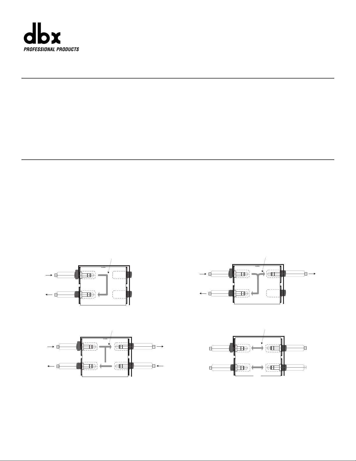
(1-A) Full-Normalled or Half-Normalled Patchbay (1-B) Half-Normalled [Mult-ed] Patchbay
(1-C) Half-Normalled Patchbay (1-D) De-Normalled Patchbay
[With Rear-Panel Normal Connection Broken]
Figure 1: Normalled, Half-Normalled and De-Normalled Patchbay Operation
2
The PB-48 is shipped from the factory with its circuit boards installed for
half-normalled patchbay operation. Normalled means that audio signal
automatically flows between a vertical pair of patchbay jacks without the
need for patchcords (see Figure 1-A). Normalled patchbays may be halfnormalled or full-normalled. In the half-normalled PB-48, each rear-panel
upper jack is respectively normalled to the jack directly below it as long
as nothing is plugged into the lower front-panel jack. Half-normalled
means that plugging into the upper front-panel jack does not break the
connection between the upper and lower rear-panel jacks, but splits the
signal to two destinations, while plugging into the lower front-panel jack
breaks the connection (see Figures 1-B and 1-C). Note: Afull-normalled
patch bay’s rear-panel connections are broken when plugging into either
front-panel jack.
A simple example of using half-normalled operation: connect a mixer ’s
monitor out to one of the PB-48’s rear-panel upper jacks, then connect
the rear-panel jack directly below it to a power amplifier. The “normalled”
signal will flow from the mixer monitor out to the power amplifier, and will
only be broken when a connection is made to the corresponding frontpanel lower jack.
Congratulations on purchasing the dbx PB-48 rackmountable patchbay.
The PB-48 features 48 front panel patchpoints and 48 rear panel patchpoints, from 24 user-adjustable board assemblies that can be configured
for Half-Normalled or De-Normalled patchbay operation without soldering or cutting wires. The PB-48 is a rugged, noise-free, patchbay
designed to serve all your patchbay needs, from providing clear and
easy access to your mixer and other studio gear, to reducing the wear
and tear on their jacks, to facilitating quick and precise re-routing of
devices within your studio setup. PB-48 patchbay jacks accept balanced
TRS or unbalanced TS standard audio 1/4” plugs.
We recommend that you take a moment and read through this instruction sheet as it provides information that will assist you in using your
patchbay to its fullest. Explanations of standard patchbay jargon, with
plenty of pictures, are included to help de-mystify common patchbay
points of entanglement and clear up any misunderstandings you might
have. Examples, suggestions and tips are provided as a starting point
only. Experiment with different setups, so that you find the setup that
best fits your system.
®
1
SIGNAL FLOW
SIGNAL FLOW
IN
OUT
BACK
FRONT
SOURCE
TO LOAD
IN
OUT
BACK
SOURCE
TO LOAD 1
FRONT
SIGNAL FLOW
FRONT
SOURCE 1
TO LOAD 2
IN
OUT
BACK
SIGNAL FLOW
FRONT
OUT
TO LOAD 1
IN
SOURCE
BACK
OUT
TO LOAD 2
Page 2
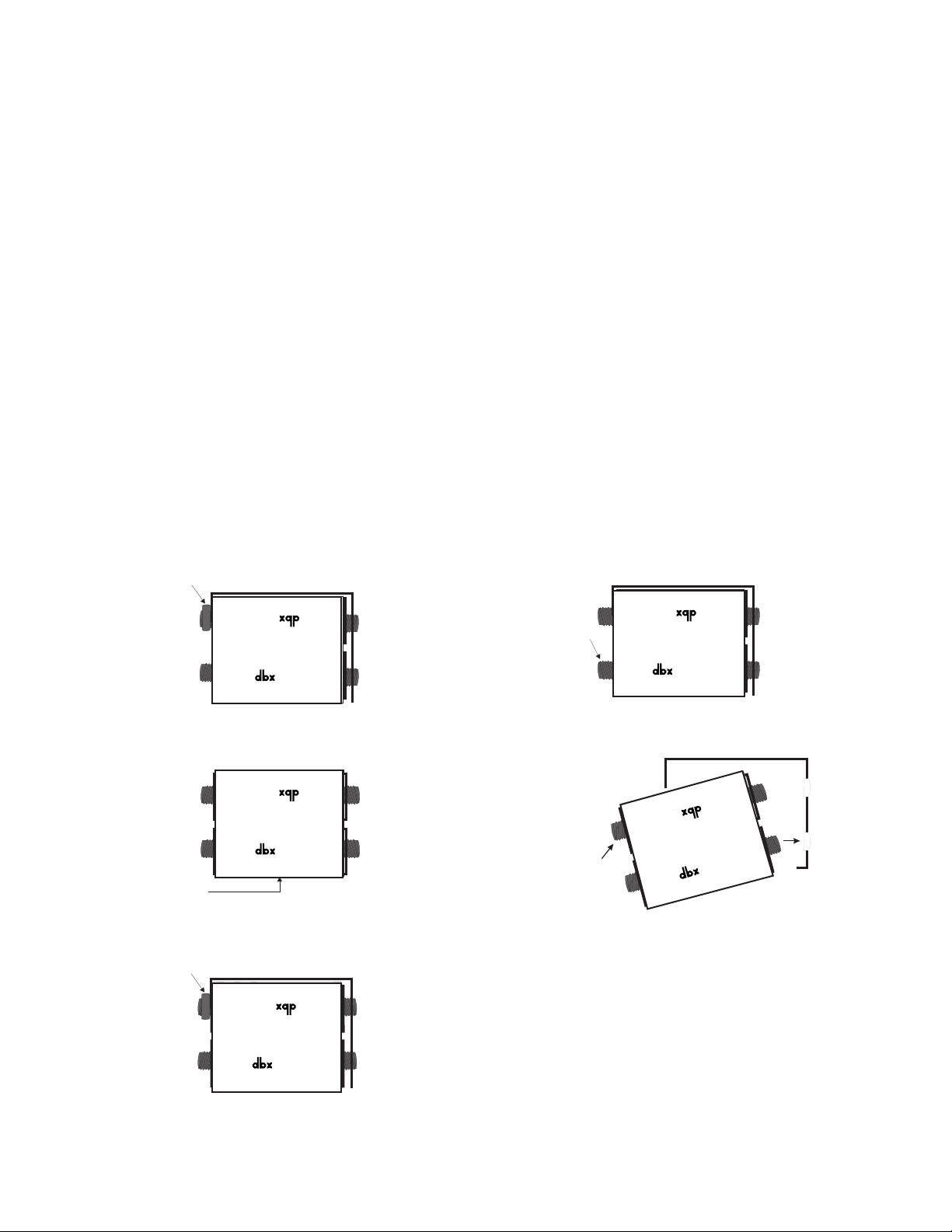
(2-A) Unscrew rear panel nut and save it. (2-B) Push down on rear lower jack, and snap board out
(2-C) Keeping circuit board component side facing you, (2-D) Angle board in (front lower jack to lower front hole), and
rotate the board 180˚. push rear upper jack (in and up) to snap board into place.
(2-E) Re-tighten upper jack with nut from step A.
Figure 2: De-Normalled Configuration Steps (to Re-Normalize, repeat steps)
The front-panel upper jacks in a half-normalled/normalled patchbay are
usually considered to be outputs because each front-panel upper jack is
wired directly to its corresponding rear-panel upper jack, where the audio
source is connected (see Figure 1-B). For example, in the half-normalled
situation, connecting from a front-panel upper jack output to the input of a
headphone amp allows you to “listen in” to the signal from the corresponding rear jack. This setup is sometimes called a Mult-ed patch,
because the patchbay simultaneously routes the rear-panel signal (i.e.,
signal fed to the rear upper jack) to multiple points: one output to the
rear-panel lower jack and one output at the front-panel upper jack. Apossible setup might have a mono mix sent to the rear upper jack, the routed
signal at the lower rear jack fed to the power amp, and the routed signal
at the front-panel upper jack connected to a tape recorder input for a
mono tape mix.
The front-panel lower jacks in a half-normalled/normalled patchbay are
called inputs because each front-panel lower jack is wired directly to its
corresponding rear-panel lower jack which is connected to an equipment
input. Plugging into a front-panel lower jack interrupts the signal fed from
the corresponding rear-panel upper jack and provides a new input source
to the rear-panel lower jack (see Figure 1-C). For example, inserting a
DAT recorder signal into the front-panel lower jack routes the tape signal
directly to the corresponding rear-panel lower jack. Note, however, that
the front-panel upper jack retains the signal from the rear-panel upper
jack.
The front-panel lower jack input can also be used to alter its corresponding rear-panel upper jack signal when the board assembly is correctly
patched to a signal processor (e.g., an equalizer, compressor, gate, etc.).
Start with a mixer and amp connected to one vertical pair of the patchbay’s rear-panel jacks, as described before. Then, connect the frontpanel upper patchbay jack (which has the mixer’s output signal) to the
processor’s input, and connect the processor’s output to the front-panel
lower jack input which feeds the amp.
To connect devices like effects or signal processors directly to the PB48’s rear panel jacks, so that they are accessible through a vertical pair
of front panel patchpoints, the PB-48 must be De-Normalized (see Figure
1-D for example and Figure 2 for customization instructions).
In a De-Normalled (or Non-Normalled) patchbay, each front panel jack
is routed directly and only to the corresponding rear-panel jack (i.e., first
upper front to first upper rear, first lower front to first lower rear, etc.). The
purpose for de-normalled patch points is convenience so that equipment
rear-panel jacks are easily accessible. De-normalled operation is useful
with effects devices or other input/output devices for which there is no
“normal” connection between it and other equipment. For example, a
compressor’s inputs and outputs may be patched into the insert point of
any mixer channel or may be used on the master outputs at mixdown
and, therefore, has no “normal” connection. Also, for consistency, the
usual patch bay setup connects outputs to rear-panel upper jacks and
inputs to rear-panel lower jacks, so normalling this vertical pair would
cause an effects device’s output to be connected directly back to its
input. This unintentional normalling is not only useless, but feedback from
output to input can cause the equipment to oscillate and emit a nasty
shriek.
Although a De-Normalled circuit board eliminates the opportunity to
“mult” outputs, the number of possible “straight” signal connections is
increased. For example, to provide access to all the inputs of a 16-channel mixer, connect the first eight pairs of the patchbay’s rear-panel jacks
respectively to the 16 mixer inputs. Now, plugging a synthesizer into one
of the front-panel patchpoints routes the synthesizer signal directly to the
corresponding mixer input. Note that all of this can be accomplished
using only 1/3 of the patchbay. The drawback, of course, is that any connection to a de-normalled patch point must be made with a patch cable.
2
®
D
N
®
®
N
D
®
D
N
®
D
N
®
®
D
N
®
®
®
N
D
®
®
N
D
®
Note that when a board assembly has been de-normalled,
a large “D: will be visible below the dbx logo at the bottom
of the board assembly. For boards that are in the half-normalled configuration, a large “N” (for normalled) will be visible below the dbx logo. These “D” and “N” indicators are
visible at the bottom of each board assembly even when
the boards are secured in the patchbay frame.
UNSCREW
PUSH
HERE
®
FRONT
FRONT
PUSH IN AND UP
BOARD AFTER 180 ROTATION
°
(logo on bottom)
TIGHTEN
FRONT
FRONT
Page 3
EXAMPLES OF PATCHBAY SETUPS
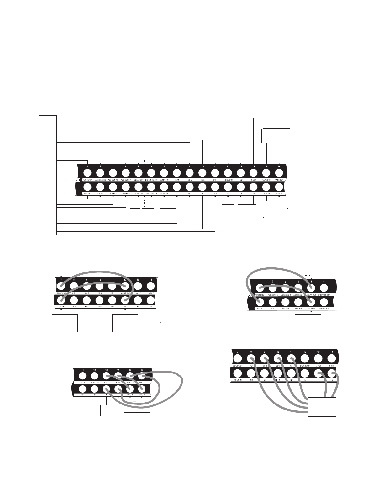
Figure 3: Possible Initial Patchbay Setup
(Examples of patchpoints for this setup are shown below)
(3-A) Patching ACompressor To A Monitor (Mono) Mix (3-B) Patching An Effects Device To A Mixer Aux Channel
(3-C) Patching a Tape Recorder To The Main Outs (3-D)Patching a Multitrack Tape Recorder Into The System
In this example, the PB-48 supports:
1 4-channel mixer: 4 inputs
4 direct outs
4 aux sends and returns
1 monitor (mono) output
L/R stereo outputs
2 effects devices (e.g., delay, enhancer)
1 signal processor (e.g., compressor)
1 2-track cassette deck
1 4-track recorder (in Figure 3-D)
It is common to set up your patchbay with some boards normalled and
others de-normalled, so that your front panel patchpoints are as flexible
as required and you maximize patchbay real estate as much as possible.
For example, to compress a mixer’s mono out signal, consider the following (as shown in Figure 3): keep one circuit board normalled, as shipped
(e.g., #12), and connect the mixer’s mono output to its rear upper jack,
then connect the power amp input to its rear lower jack; de-normalize a
different circuit board (e.g., #7) and add a compressor to this board by
connecting the compressor input to its rear lower jack and the compressor output to its rear upper jack. To compress the mono output via the
PB-48’s front panel patchpoints (Figure 3-A), connect the mono output to
the compressor input with a patch cable from the normalled front upper
jack to the de-normalled front lower jack, then connect the compressor
output to the power amp with a patch cable from the de-normalled front
upper jack to the normalled front lower jack. Other examples are shown
in Figures 3-B through 3-D. It should be noted that since this patch bay is
TRS, other applications may include using stereo unbalanced signals
(tip-left, ring-right, sleeve-ground) or unbalanced insert signals (tip-return,
ring-send, sleeve-ground for example) on a single “2-conductor plus
shield” cable.
3
2. ALL CONNECTIONS SHOWN ARE TO REAR OF PATCH BAY
Tape
Recorder
Out In Out In
L L R R
Tape
Recorder
Out In Out In
L L R R
OUT OUT
IN
IN 4-TRACK
IN RECORDER
IN
R
MAIN OUT
L
MONO OUT
4
DIRECT
3
OUTS
2
1
4
3
AUX
2
SENDS
1
MIXER
(4-CHANNEL)
RETURNS
INPUTS
1
AUX
2
3
4
NOTES: 1. D=DE-NORMALLED; N=NORMALLED
1
2
3
4
DDDDDDDDDDDDDDDDDDDDDDNNNNNNNNN
OUT IN OUT IN IN OUT
DELAY ENHANCER
2. ALL CONNECTIONS TO REAR OF PATCH BAY
COMPRESSOR
TAPE
RECORDER
OUT IN OUT IN
L R L R
N
IN ININ
POWER AMPMONITOR
AMP
TO SPEAKERS
TO SPEAKERS
DDDDDDDDDDNNNNN
N
ININ OUT
COMPRESSOR
MONITOR
AMP
TO SPEAKERS
TAPE
RECORDER
OUT IN OUT IN
L R L R
(OUTER PATCH CABLES
FOR PLAYBACK)
DDDDDDDDDDNNNNN
DDNNNNNNNNN
N
IN IN
POWER AMP
TO SPEAKERS
DDDDDDDDDDD
OUT IN
DELAY
IN
IN
DAT
IN
IN
D
OUT OUT
N
Page 4

PATCHBAY TIPS
WARRANTY
Limited Warranty
This warranty is valid only for the original purchaser. We warrant dbx products against defects in material or workmanship for a period of two years
from the date of original purchase for use, and agree to repair or, at our option, replace any defective item, except external power transformers, without
charge for either parts or labor.
IMPORTANT: This warranty does not cover damage resulting from accident, misuse or abuse, lack of reasonable care, the affixing of any attachment
not provided with the product, loss of parts, or connecting the product to any but the specified receptacles. This warranty is void unless service or
repairs are performed by an authorized service center. No responsibility is assumed for any special, incidental or consequential damages. However,
the limitation of any right or remedy shall not be effective where such is prohibited or restricted by law.
Simply take or ship your dbx product prepaid to our service department. Be sure to include your sales slip as proof of purchase date. (We will not
repair transit damage under the no-charge terms of this warranty.) dbx will pay return shipping.
NOTE: No other warranty, written or oral is authorized for dbx products.
This warranty gives you specific legal rights, and you may also have other rights which vary from state to state. Some states do not allow the exclusion of limitations of incidental or consequential damages or limitations on how long an implied warranty lasts, so the above exclusion and limitations
may not apply to you.
S
PECIFICATIONS
Patch Points: 48 (2 rows of 24)
Jacks: 1/4” phone, balanced or unbalanced, nickel-silver, self-cleaning contacts
Normalling: Half-normalled or de-normalled (user configurable)
Chassis Dimensions (H x W x D): 1.75” x 19” x 2.6” (44mm x 482mm x 68mm)
Module Dimensions (H x W x D): 1.4” x 0.6” x 2.6” (40mm x 18mm x 68mm)
Shipping Weight: 2.3 lb (1.1 kg)
This manual is part number 18-2128-B. © Copyright 1996 by dbx Professional Products.
8760 South Sandy Parkway
Sandy, Utah 84070
TEL: (801) 568-7660
FAX: (801) 568-7662
❒ Make sure you always label the front panel jacks, so you remember
how the patchbay is connected to your system. Use a colored pencil
that won’t rub off easily, but that can be erased if you make changes.
Furthermore, it might prove helpful to use one color for normalled patch
points and another color for de-normalled patch points. (Note: Use of
solvents could damage the front panel finish.)
❒ The PB-48’s jacks have pure nickel-silver, self-cleaning contacts
which will provide many years of use. Use only standard audio 1/4”
plugs. Other styles of plugs while appearing to fit, can in fact deform the
contacts.
❒ Keep cables to a minimum length. Generally, most professional equip-
ment will drive at least 50 feet of commonly used shielded cable without
audible signal loss. Note that the longer the cable run, the more the
quality of the cable becomes critical.
❒ Maintain a supply of patchcords of various cable lengths, so you can
make connections rapidly and effectively.
❒ When mounting the unit in a rack; do not wedge it between two other
units that are much deeper, as measured from front to back; for easy
access to rear-panel jacks.
❒ Set the patchbay as close to eye level as possible to complement the
patchbay’s ability to simplify your system connections. (Consider if your
eye level is usually from a sitting or standing position).
❒ Although a normalled circuit board can support two “straight” signal
lines, we recommend you de-normal the circuit board, for situations previously described, to reduce feedback or the chance of oscillations
through unintentional signal loops.
❒ Do not waste real estate. Set up your patchbay to meet as many of
your needs as possible, while providing the most flexibility. Remember,
de-normalled operation reduces the chance of feedback.
❒ Do not overpatch. If there is a simple route, take it. Even if it means
having to de-normal a patch. This feature is provided to serve long term
needs. Use it.
❒ Do not be afraid to change your patchbay setup. New connections
might serve you better. Chances are if you’re thinking about a change,
then the change has merit. If you are concerned about forgetting a previous setup, just jot it down clearly.
4
®
A Harman International Company
 Loading...