

Page 1
PRODUCT DATA SHEET
cy
ng)
ng
ACTUATOR
LA30
Features:
• 12/24V DC permanent magnet motor
• Max. thrust up to 6000 N (LA30LK)
• Stainless steel piston rod
• Elegant and compact construction with small
installation dimensions
• Protection class: IP51 / IP66
• Colour: black
• Speed max. 65 mm/s (LA30 S-motor with 12 mm
pitch)
• Low noise level
• Steel construction for all bearing parts
• Acme thread spindle for optimum efficiency
Options:
• Extra powerful motor (S-motor)
• L-motor for system actuator
• IP66 (by ordering LA30 with plastic housing)
• Double-acting brake - increased self-locking
ability (LA30 with 6 or 9 mm pitch + LA30 S-motor
with 6 or 9 mm pitch and LA30L) which ensures
that all these types are fully self-locking
• Potentiometer for positioning the actuator. 0-1 K
ohm, 0-5 K ohm or 0-10 K ohm
• Optical encoder for positioning the actuator. 10
pulses pr. spindle revolution
• Reed switch (only LA30 L-motor versions): 8 pulses
pr. spindle revolution
• Mechanical spline function. Safety feature by
using the mechnical spline, the actuator
can only push
• Safety nut (only in push)
• Terminal cover (only LA30 L-motor versions)
• Ball screw (K) (only LA30 L-motor versions)
• Ball screw and safety nut (KAS) (only LA30 L-motor
versions)
• Ball screw, safety nut and splines (KSM) (only LA30
L-motor versions)
Usage:
• Duty cycle: Max. 10% or 6 min/hour at continuous
use
• Ambient temperature +5° to +40°C
• Storage temperature -40° to +70°C
• Compatible with control boxes CB8, CB12, CB14,
CB18
• Should LA30 be used with a non LINAK control
unit, please ask the nearest Linak representative
for further details.
all
12 mm
-motor
nsures
r. 0-1 K
tor. 10
pulses
e by
LA30 is a powerful actuator yet small enough to
fit to most applications.
The actuator can be supplied with options such
as built-in potentiometer for servo operation or
an extra powerful motor for increased speed
and strength (S-motor).
In addition to industrial and agricultural applications, the actuator is also ideal for positioning
satellite dishes.
The system actuator LA30L (option) can be combined with LINAK control boxes and it is perfet
for a variety of furniture applications.
Page 2
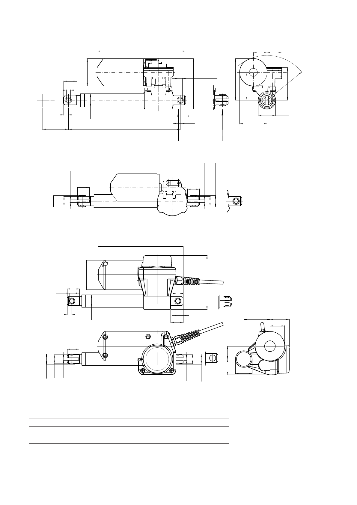
Dimensions:
203.5
31 34
115.5
13
Ø
+0.2
10.1
0
6.1
+0.2
0
95
02 = turned 90
0
-0.2
25.9
3
75
10
64
R
40Ø
63
o
LINAK A/S
LA30002A
63Ø
30
+0.2
Ø
10.1
0
11
30Ø
30
S
S+156
01 = standard
+0.2
0
6.1
28
0
-0.2
28
25.9
21.9Ø
204.5
21.9Ø
71Ø
30
10.1Ø
11
28
+0.2
-0.2
0
21.9Ø
6.1
0
25
LINAK A/S
LA30001B
30Ø
13
30
+0.2
0
6.1
129.5
10.1Ø
0
-0.2
21.9Ø
25
Installation dimension:
LA30 L-motor + LA30 + LA30 S-motor with 3 or 6 mm pitch S + 156 mm
LA30 with spline + LA30 S-motor with 9 mm pitch S + 167 mm
LA30 with brake + LA30 S-motor with 3 or 6 mm pitch with brake S + 189 mm
LA30 with ball screw and L-motor / LA30 ball screw and safety nut S + 194 mm
LA30 L-motor with brake + LA30 S-motor 9 or 12 mm pitch with brake S + 199 mm
LA30 L-motor with ball screw, safety nut and spline S + 251 mm
63
31
38
40
46.5
35.5
Page 3
LA30
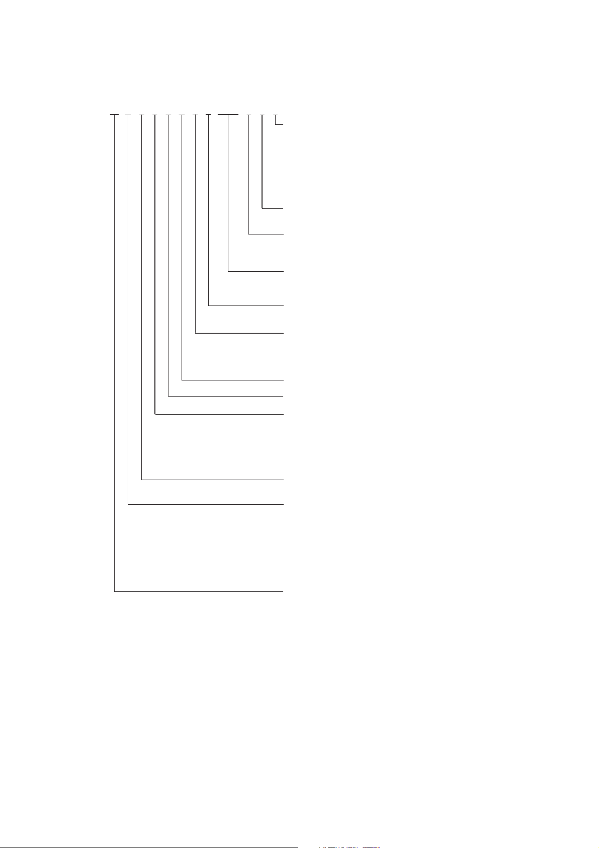
Ordering example:
30
1
1
-
0
0
0
5
0
0
2
0
0
0
Cables:
Protection class:
Motor:
Stroke length:
Install. dim.:
N = No cable when IP51 (except reed)
0 = Straight with jack plug 2300 mm
1 = Straight with jack plug 1050 mm
2 = Coiled with jack plug 400 mm
3 = Coiled with jack plug 200 mm
4 = Straight without plug 500 mm (Potentiometer)
5 = Straight without plug 1200 mm (with IP66 housing)
X = Other cable/length
0 = IP51
2 = IP66 with plastic house
0 = 24 V DC
1 = 24 V S-motor
2 = 12 V S-motor
XXX = mm
0 = Standard
X =Other installation dimension
4 = 24 V L-motor for LINAK control boxes
5 = 12 V motor
Max. with 3 & 6 mm pitch 400 mm
Max. with 9 & 12 mm pitch 500 mm
Min. 50 mm
7 = 36 V motor
Option:
Colour:
Option:
Option:
Back fixture:
Spindle type:
Actuator type:
0 = None
1 = Safety nut
2 = Steel spline
3 = Steel spline with safety nut
- = Black
0 = None
0 = None
P = Potentiometer 1 Kohm
L = Potentiometer 5 Kohm
T = Potentiometer 10 Kohm
R = Reedswitch
D = Optical encoder
1 = Standard (01)
2 = Turned 90
1 = 3 mm
2 = 6 mm
3 = 9 mm
4 = 4 mm
5 = 2.5 mm
6 = 2 mm
7 = 12 mm
K = Ball spindel
LA30
4 = Brake
5 = Brake with safety nut
o
(02)
(1-tread)
(2-tread)
(3-tread)
(2-tread)
(1-tread)
(1-tread)
(4-tread)
Old type no.
LA30.1
LA30.2
LA30.3
LA30.40
LA30.25
LA30.20
LA30.4
LA30K
Page 4

Speed and current graphs:
LA30 24V motor
8
7
6
5
4
3
Ampere
2
1
0
0 500 1000 1500 2000 2500 3000 3500
12mm
9mm
Load (N)
6mm
3mm
LA30 24V S-motor
12
10
8
6
Ampere
4
2
0
0 500 1000 1500 2000 2500 3000 3500
12mm 9mm
Load (N)
6mm
3mm
LA30 24V L-motor
5
4
3
2
Ampere
1
0
0 1000 2000 3000 4000 5000 6000 7000
9mm
12mm
6 mm
Load (N)
4mm
Ball screw
3mm
60
50
40
30
20
Speed mm/s
10
12mm
9mm pitch
6mm pitch
9mm
6mm
0
0 500 1000 1500 2000 2500 3000 3500
Load (N)
70
60
9mm pitch
12mm pitch
12mm
6mm pitch
50
40
30
20
Speed mm/s
10
9mm
6mm
3mm
0
0 500 1000 1500 2000 2500 3000 3500 4000
Load (N)
30
30
25
25
20
20
15
15
10
10
Speed mm/s
Speed (mm/s)
5
5
0
0
9mm pitch
12mm pitch
12mm
12mm
9mm
9mm
6mm
6mm
6mm pitch
4mm
Ball screw
3mm
3mm
0 1000 2000 3000 4000 5000
0 1000 2000 3000 4000 5000 6000 7000
Load (N)
Load (N)
3mm pitch
3mm
3mm pitch
3mm pitch
LA30 12V motor
16
14
12mm pitch
12
10
8
Amp.
6
4
2
0
0 500 1000 1500 2000 2500 3000 3500 4000
9mm pitch
Thrust (Nm)
6mm pitch
3mm pitch
LA30 12V S-motor
25
12mm pitch
20
15
Amp.
10
5
0
0 500 1000 1500 2000 2500 3000 3500 4000
9mm pitch
Thrust (Nm)
6mm pitch
3mm pitch
60
50
40
30
20
Speed mm/s
10
9mm pitch
12mm
6mm pitch
9mm
6mm
0
0 500 1000 1500 2000 2500 3000 3500
Load (N)
70
60
9mm pitch
12mm pitch
12mm
6mm pitch
50
40
30
20
Speed mm/s
10
9mm
6mm
3mm
0
0 500 1000 1500 2000 2500 3000 3500 4000
Load (N)
3mm pitch
3mm
3mm pitch
Page 5

Technical specifications:
New type Old Spindle Thrust *Self-lock Typical Stroke length Typical
type pitch max. max. With/ speed amp.
without 0/full at full
brake load load
(mm) (N) (N) (mm/s) (mm) 12V 24V
307xx0-4xxxx0/5xx LA30.4B 12 1000 1000/0 48/24 50 100 150 200 250 300 350 400 14 7
303xx0-4xxxx0/5xx LA30.3B 9 1500 1500/400 42/20 50 100 150 200 250 300 350 400 14 6.9
302xx0-4xxxx0/5xx LA30.2B 6 2000 2000/500 18.5/14 50 100 150 200 250 300 350 400 14 7
301xx0-xxxxx0/5xx LA30.1 3 3000 3000/3000 16/9 50 100 150 200 250 300 350 400 14 6.4
307xx0-4xxxx1/2xx LA30.7SB 12 1000 1000/0 65/35 50 100 150 200 250 300 350 400 20 10
303xx0-4xxxx1/2xx LA30.3SB 9 1800 1800/0 52/25 50 100 150 200 250 300 350 400 20 10
302xx0-4xxxx1/2xx LA30.2SB 6 2400 2400/500 34/20.3 50 100 150 200 250 300 350 400 18 9.1
301xx0-xxxxx1/2xx LA30.1S 3 3500 3500/3500 17/9.5 50 100 150 200 250 300 350 400 18 9.3
307xx0-4xxxx4xx LA30.4LB 12 1000 1000/0 26/20 50 100 150 200 250 300 350 400 - 2.5
303xx0-4xxxx4xx LA30.3LB 9 2000 2000/0 20/13 50 100 150 200 250 300 350 400 - 4.4
302xx0-4xxxx4xx LA30.2L 6 3000 3000/2000 13.8/7 50 100 150 200 250 300 350 400 - 4
301xx0-xxxxx4xx LA30.1L 3 4000 4000/4000 7/4.5 50 100 150 200 250 300 350 400 - 3.5
30Kxx0-0xxxx4xx LA30.LK 4 6000 6000/n/a 8.7/5.5 - - 150 200 250 300 350 400 - 4.7
30Kxx0-1xxxx4xx LA30.KAS 4 6000 6000/n/a 8.7/5.5 - - 150 200 250 300 350 400 - 4.7
30Kxxo-3xxxx4xx LA30.LKSM 4 6000 6000/n/a 8.7/5.5 - 100 150 200 250 300 350 400 - 4.7
The above measurements are made with the actuators connected to a stable power supply, LA30 L-motor versions with a CB12.
S = Strong motor
L = Slow motor
K = Ball screw
KAS = Ball screw, safety nut
KSM = Ball screw, safety nut, spline
All stroke lengths marked with background shading give full resolution with the standard potentiometer (1; 5 or 10 K ohm).
A potentiometer may be used with other stroke lengths but will not give full resolution.
LA30 Actuator with potentiometer
+
Black
Blue
Brown
Red /
Yellow
Green /
White
LA30 Actuator with optical encoder
Green
+
Yellow
Pulses
Black
Earth
Red
+5V DC
Optical encoder
Red / Yellow Green / White
+
+
Out going
In going
LA30 Actuator with reed ( only possible with 24V L-motor )
3.9 k
Brown
Black
+
+
Out going
In going
Pulse
Blue
Blue
Black
Brown
Please note that the voltage level og feedback signal depends on the actuator load.
Page 6

Thrust v’s Duty cycles for LA30 3 mm pitch Thrust v’s Average cycles for LA30 3 mm pitch
Duty Cycle v's Load - LA30 L-motor, 3 mm pitch (24 V)
4500
4000
3500
3000
2500
2000
Load (N)
1500
1000
500
0
0% 20% 40% 60% 80% 100%
Duty Cycle (%)
Duty Cycle v's Load - LA30 S-motor, 3 mm pitch (24 V)
4000
3500
3000
2500
2000
Load (N)
1500
1000
500
0
0% 30% 60% 90%
Duty Cycle (%)
Average Cycles v's Load - LA30 L-motor, 3 mm pitch
4500
4000
3500
3000
2500
2000
Load (N)
1500
1000
500
0
10 30 50 70 90 110
Average Cycles v's Load - LA30 S-motor, 3 mm pitch
4000
3500
3000
2500
2000
Load (N)
1500
1000
500
0
20 40 60 80 100 120 140
(24 V)
Average Cycles (X 1.000)
(24 V)
Average Cycles (X 1.000)
Thrust v’s Duty cycles for LA30 6 mm pitch Thrust v’s Average cycles for LA30 6 mm pitch
Duty Cycle versus Load - LA30.2L - 6 mm pitch (24 V)
3500
3000
2500
2000
1500
Load (N)
1000
500
0
0% 20% 40% 60% 80% 100%
Duty Cycle (%)
Duty Cycle versus Load - LA30.2S - 6 mm pitch (24 V)
3000
2500
2000
1500
Load (N)
1000
500
0
0% 20% 40% 60% 80% 100%
Duty Cycle (%)
Average Cycles versus Load - LA30.2L - 6 mm pitch (24 V)
4500
4000
3500
3000
2500
2000
Load (N)
1500
1000
500
0
20 40 60 80 100 120 140 160 180 200
Average Cycles (X 1.000)
Average Cycles versus Load - LA30.2S - 6 mm pitch (24 V)
4000
3500
3000
2500
2000
Load (N)
1500
1000
500
0
30 80 130 180 230
Average Cycles (X 1.000)
Page 7

Thrust v’s Duty cycles for LA30 9 mm pitch Thrust v’s Average cycles for LA30 9 mm pitch
Duty Cycle versus Load - LA30.3L - 9 mm pitch (24 V)
2500
2000
1500
Load (N)
1000
500
0
0% 20% 40% 60% 80% 100%
Duty Cycle (%)
Duty Cycle versus Load - LA30.3S - 9 mm pitch (24 V)
2000
1800
1600
1400
1200
1000
Load (N)
800
600
400
200
0
0% 20% 40% 60% 80% 100%
Duty Cycle (%)
Average Cycles versus Load - LA30.3L - 9 mm pitch (24 V)
2500
2000
1500
1000
Load (N)
500
0
30 80 130 180 230 280 330
Average Cycles (X 1.000)
Average Cycles versus Load - LA30.3S - 9 mm pitch (24 V)
2000
1800
1600
1400
1200
1000
Load (N)
800
600
400
200
0
60 110 160 210 260 310 360 410 460
Average Cycles (X 1.000)
Thrust v’s Duty cycles for LA30 12 mm pitch Thrust v’s Average cycles for LA30 12 mm pitch
Duty Cycle versus Load - LA30.4L - 12 mm pitch (24 V)
1200
1000
800
600
Load (N)
400
200
0
0% 20% 40% 60% 80% 100%
Duty Cycle (%)
Duty Cycle versus Load - LA30.4S - 12 mm pitch (24 V)
1200
1000
800
600
Load (N)
400
200
0
0% 20% 40% 60% 80% 100%
Duty Cycle (%)
Average Cycles versus Load - LA30.4L - 12 mm pitch (24 V)
1200
1000
800
600
Load (N)
400
200
0
45 145 245 345 445 545
Average Cycles (X 1.000)
Average Cycles versus Load - LA30.4S - 12 mm pitch (24 V)
1200
1000
800
600
Load (N)
400
200
0
75 175 275 375 475 575 675 775
Average Cycles (X 1.000)
Page 8

Accessories for LA30:
Control card
Limit Switch
The CS16 electronic limit switch is connected between the LINAK®
actuator and a non-LINAK power supply, where it cuts out the
current to the actuator in end position or if an obstacle is encountered. The PCB contains a variable current limit setting and is
available in different versions, depending on which actuator it is
to be used with.
Above mentioned guarantees the maintenance of the long life of
the LINAK actuator. The CS16 is an important component which
ensures a long life for the actuator.
There are two types of LINAK® limit switches, for LA30, LS and LSD.
The LSD type controls the stroke length of the actuator between
two fixed end positions by cutting off the current to the motor.
The LS type gives signal in two fixed end positions, but requires
a control unit to stop the actuator when the micro switches are
activated.
Bellows
• Give a better protection and therefore give a higher liftetime
of the actuator
• Protects inner tube against dust and dirt
• Can be used for actuators: LA30
• Does not change the IP rating
• Available in black colour
• Ask for special folder
Please contact your nearest LINAK dealer for further details or read more on www.linak.com.
It is the responsibility of the product user to determine the suitability
of LINAK A/S products for a specific application. LINAK will at point of
delivery replace/repair defective products covered by the warranty
if promptly returned to the factory. No liability is assumed beyond
such replacement/repair.
Specifications subject to change without prior notice.
Copyright © LINAK 07.01 MA M9-02-050-J . Chapter 5.7
 Loading...