

Page 1
Photocoupler
Signal transmission between circuits of different potentials and impedances.
Part Name: LA214
Features
‧
SOP package 4 Pin type in miniature design
‧600% minimum current transfer ratio
‧ 1500V rms Input/Output isolation
‧ AC input.
Applications
‧ Telephones
‧ Programmable controllers
‧ System appliances, measuring instruments.
‧
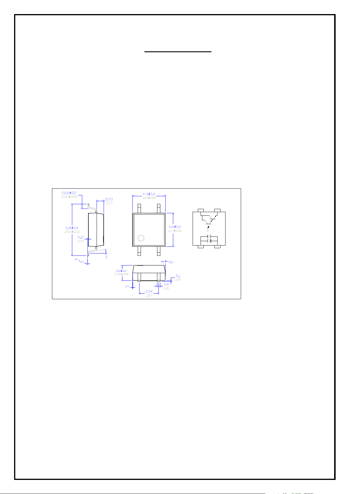
Dimensions(Unit: mm inch)
Letex
LA214
A
16
34
21
1. LED Anode, Cathode
2. LED Cathode, Anode
3. Emitter
4. Collector
34
1 2
- 1 - Letex Technology Corp.
Page 2
Photocoupler
(Ambient Temperature: 25
Reverse Voltage
Collector to Emitter Voltage
Emitter to Collector Voltage
Veco
I/O Breakdown Voltage
Vrms
Storage Temperature
Tstg
Operating Temperature
Soldering Temperature
(Ambient Temperature: 25
Forward Voltage
Input
C Breakdown Voltage
Veco
Output
Vce=20V, I
Current Transfer Ratio
Collector Saturation Voltage
Vce=5V, Ic=2mA,
Coupled
Part Name: LA214
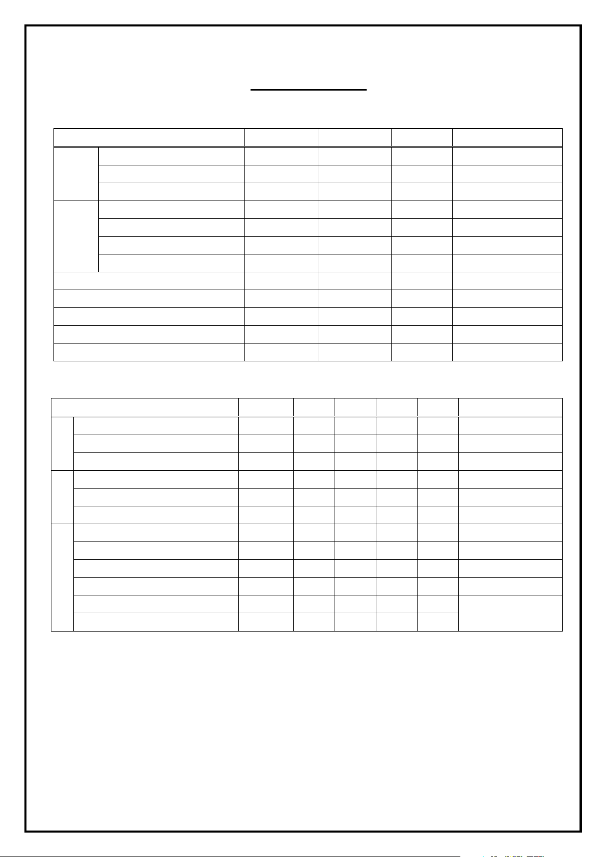
Absolute Maximum Ratings
Forward Current IF 50 mA
Input
Peak Forward Current IFP 1 A
Output
Collector Current Ic 50 mA
Power Dissipation Pc 150 mW
Power Dissipation PD 200 mW
Electrical Specifications
Item Symbol Rating Units Note
VR 5 V
Vceo 40 V Ic=1mA, IB=0
VI/O 1500
Top -55 to +100
TSol 260
Item Symbol MIN. TYP. MAX. Units Conditions
℃)
6 V IE=100µA, IB=0
-55 to +125
℃)
℃
℃
℃
RH=60%, 1min
10 seconds max.
Reverse Current IR - µA
Junction Capacitance Ct 30 pF V=0, f=1.0KHz
C-E Breakdown V oltage Vceo 35 V Ic=0.5mA
ECollector Dark Current Iceo 100 nA
Isolation Resistance RI/O 10
Isolation Capacitance CI/O 1.0 pF V=0, f=1.0MHz
Rise Time
Fall Time
VF 1.2 1.4 V IF= ± 20mA
6 V Ie=0.1mA
F=0
CTR 600 1600 7000
Vce(sat) 1 V IF=±20mA, Ic=1mA
9
tr
tf
300 µs
250 µs
﹪
IF= ± 1mA, Vce=5V
Ω
V=500V DC
RL=100Ω
- 2 - Letex Technology Corp.
Page 3
Photocoupler
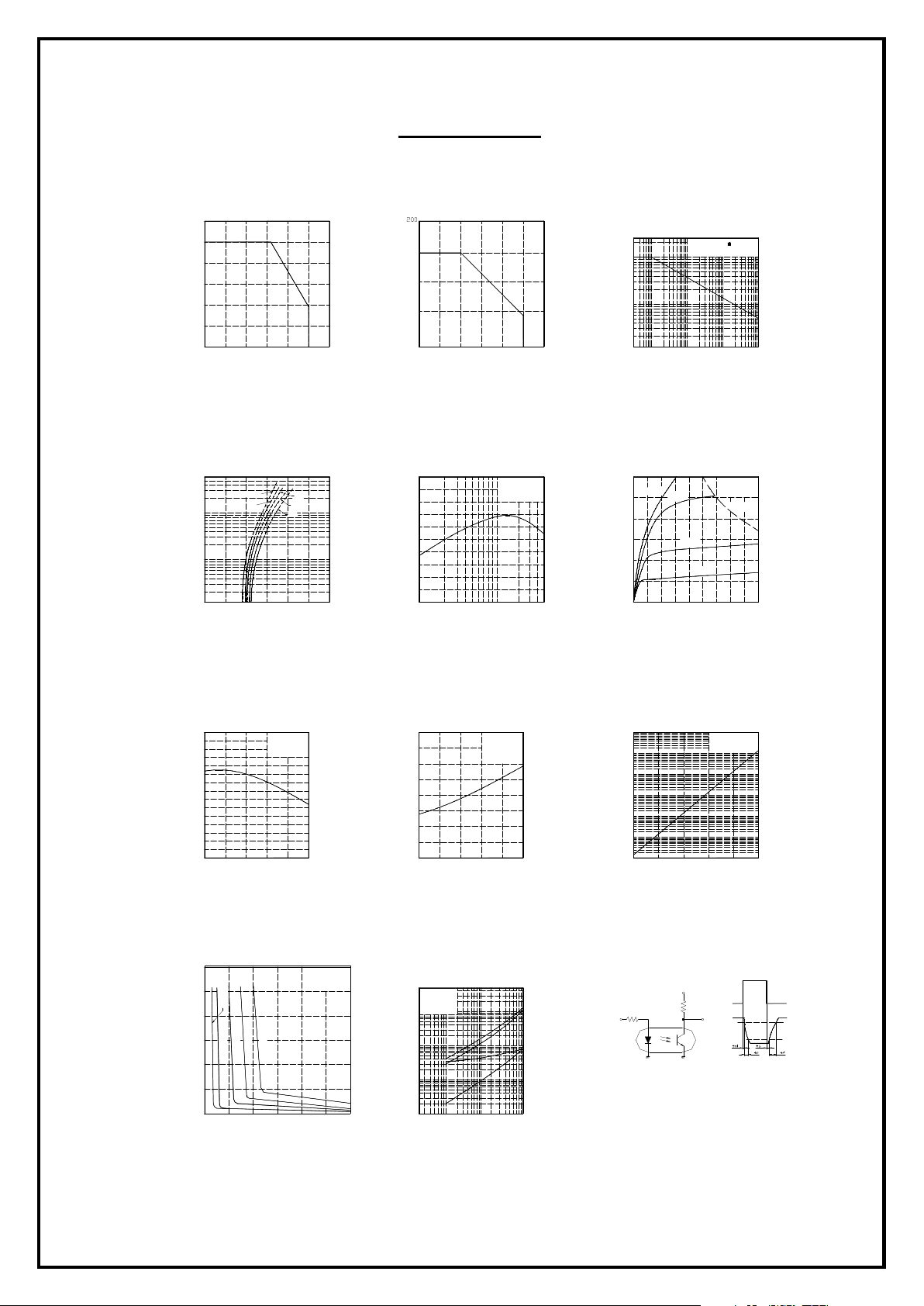
Reference Data
Collector-Emitter satureation voltage (V)
Forward current (mA)
Ambient temperature (
Ambient temperature (
Collector power dissipation (mW)
Peak forward current (
Forward current (mA)
Collector current (mA)
Collector-Emitter voltage (V)
Ambient temperature (
Collector-Emitter saturation voltage (V)
Ambient temperature (
Collector dark current (A)
Ambient temperature (
Load resistance (k
Forward current Vs.
Ambient temperature
60
50
40
30
20
Forward current (mA)
10
0
-25
0 25 100 125 0 25 125
Forward current Vs.
Forward voltage
500
200
100
50
20
10
Forward current (mA)
5
2
1
0
75 50 -25
℃
)
Ta = 75℃
Forward voltage (V)
25℃
50℃
0℃
25℃
3.0 2.5 1.0 0.5 1.5 2.0
Collector power dissipation Vs.
Ambient temperature
150
100
50
0
Current transfer ratio Vs.
Forward current
200
180
160
140
120
100
80
CTR (%)
60
40
20
1
1
2 5 10 20 50
75 50 100
℃
)
Vce = 5V
Ta = 25℃
Peak forward current Vs.
Duty ratio
2000
1000
mA)
500
200
100
50
20
10
-3 -210 -110 0
5 10 2 5 5 2 5 2
Collector current Vs.
Collector-Emitter voltage
30
IF = 30mA
25
20
15
10
5
0
0
1 2 3 4 5 6 7 8 9
20mA
Pulse width 100us
Ta = 25℃
Duty ratio
10mA
5mA
10
Ta = 25℃
Pc(Max)
Relative CTR Vs.
Ambient temperature
150
100
50
Relative CTR (%)
0
-25
0 25 100 50 75
Collector-Emitter saturation voltage Vs.
Forward current
1.2
1.0
Ic=0.5mA
0.8
0.6
1mA
0.4
0.2
0
10
0
IF = 5mA
Vce = 5V
℃
)
Ta = 25℃
7mA
5mA
3mA
20 30 40 50 60
IF = 20mA
Ic = 1mA
℃
Ω)
)
Collector-Emitter saturation voltage Vs.
Ambient temperature
0.16
0.14
0.12
0.10
0.08
0.06
0.04
0.02
0
-25
0 25 100 50 75
Response time Vs.
Load resistance
500
Vce = 2V
200
Ic = 2mA
Ta = 25℃
100
50
20
10
5
2
Response time (μs)
1
0.5
0.2
0.1
0.1 0.2 0.5 1 2 5 10
Collector dark current Vs.
Ambient temperature
-5
10
-6
10
-7
10
-8
10
-9
10
-10
10
-11
10
0 25 50 75 100-25
Vce = 20V
℃
)
Test circuit for resopnse time
Vcc
RD
Input
RL
Output
Input
Output
10%
90%
- 3 - Letex Technology Corp.
 Loading...