

Page 1

User guide T2365 T2380 Matrix printer
Page 2

Page 3

User guide Table of contents
Table of contents
Introduction 1
Printer features 1
Symbols used 1
About this manual 2
Printer at a glance 3
Printer in tractor mode 4
Paperway 5
Installation 7
Unpacking the printer 7
Placing your printer 8
Checking the printer voltage 9
Connecting the printer 9
Switching on the printer 10
Inserting the ribbon cassette 11
Installing the ribbon cassette the first time 11
Changing the ribbon cassette 17
Printer drivers 23
Installing a printer driver in Windows 95/98/ME 23
Installing a printer driver in Windows 2000/2003/XP 23
Installing a printer driver in Windows 7 25
Installing a printer driver in Windows Vista 26
Other operating systems 27
Changing printer settings 28
Form settings (Windows 2000/2003/XP/Vista/
Windows 7/2008) 28
Loading optional firmware 29
Troubleshooting 29
I
Page 4

Table of contents User guide
The control panel 31
The LC display 32
Online mode 33
Offline mode 33
Setup mode 34
Messages in the LC display 35
Key functions when turning on the printer 37
Paper handling 39
Loading paper 39
Paper transport 42
Moving the paper to the tear position 43
Removing paper 44
Settings 45
Setting the print head gap 45
Setting the tear position 46
Setting the first printing line (TOF) 47
Selecting character density and font 48
2T model 49
Introduction 49
Rear tractor paper path 49
Loading paper into the rear tractor 50
Paper guiding bracket 52
Selecting the rear tractor 52
The Menu 55
Programming via the control panel 55
Enabling access to menu mode 55
Calling up the menu 55
Menu configurations 56
Menu handling 57
Save settings 57
Selecting the LC display language 58
Terminating Setup mode 59
II
Page 5

User guide Table of contents
Menu structure 60
Menu parameters 61
Printing out menu configurations (Print) 61
Loading menu configurations (Menu) 61
Reset to default values (Reset) 62
Quietmode (Quietm.) 62
Selecting font (Font) 63
Setting character density (CPI) 64
Setting line spacing (LPI) 64
Skiping perforation (Skip) 65
Selecting start signal for escape sequence (ESCChar) 65
Selecting emulation (Emulate) 66
Bidirectional printing (Bidir) 66
Settings for interfaces (I/O) 67
Serial interface (Serial) 67
Data transmission rate (Baud) 67
Data format (Format) 68
Further Settings (Special) 69
Error handling (ErrMode) 69
Block end character (Blockend) 69
Signal feedback (Remote) 70
Transparence (Handthr) 70
Protocol (Protocol) 71
Signal Processing (DTR) 71
Selecting interface (Interf.) 72
Interface buffer (Buffer) 72
Ethernet interface (ETH-INT) 73
Setting IP address (IP Addr) 73
Setting Gateway address (Gateway) 74
Setting Subnet mask (Subnet) 74
IP address administration (IP Get M) 75
Banner page (Banner) 75
Ethernet speed (EthSpeed) 76
Selecting character set (CG-Tab) 77
IBM character set (CharSet) 77
National character set (Country) 78
Slashed zero (Sl.Zero) 78
Automatic carriage return (Auto-CR) 79
III
Page 6

Table of contents User guide
Automatic line feed (Auto-LF) 79
Menu lock (MenLock) 80
Language (Language) 80
Paper parameters (Paper) 81
Form length (Forml) 81
First printing position (FormAdj) 83
Printhead gap manually (Head) 83
View and tear position (AutoTear) 84
Line length (Width) 85
Barcode (Barcode) 85
Normal characters and barcode (Barmode) 86
Vertical position after oversized barcode (BarTop) 87
Vertical position after oversized character (LCPtop) 88
Form feed mode (FFmode) 88
Setting and activating options (PapOpt) 89
Activation of tractors (AutoTra) 89
Activation of automatic sheet feeder (AutoASF) 90
Setting the left margin (LeftMrg) 90
Setting the right margin (RightMrg) 91
Local copy (screen print) from a Coax or Coax/IPDS
(FFaftLC) 91
Enable/Disable paper handling features (Paphand) 92
Menu settings (example) 93
Advanced menu 95
Test functions 95
Printer self-test (Rolling ASCII) 96
Exiting Rolling ASCII test mode 97
Interface test (Hex-Dump) 98
Printout in Hex-Dump 98
Terminating Hex-Dump 99
Advanced settings 100
Automatic paper motion sensor (PMS) 102
Form length (Forml) 103
Automatic gap adjustment (AGA) 103
Paper handling (Paphand) 104
Increasing the printhead gap (Head up) 104
Paper width (Pagewid) 105
IV
Page 7

User guide Table of contents
Left-hand area (Leftzon) 105
Right-hand area (Rightzo) 106
Physical left margin (Physlm) 106
Bidirectional parallel interface (CX-bid) 107
Line wrap (Wrap) 107
Beep at paper end (Sound) 108
Deactivate single sheet feeder (Single) 108
Settings for paper with dark back (Pap.back) 109
Setting for printing copy paper (HvyForm) 109
Power save mode (Sleepmod) 110
Automatic paper width detection (APW) 110
Automatic detection of the top paper margin (AED) 111
Serial number (SerialN) 112
Asset number (AssetN) 112
Graphic print speed (GrSpeed) 113
Improvement of graphic and barcode print quality
(GrFreq) (T2365 only) 113
Ignore characters (Ignore) 114
Ignore character (IgnorChr) 114
Activate PJL language (Jobcntl) 115
Troubleshooting 117
General print problems 118
The display remains dark 118
The display is lit, but the printer does not print 118
Problems with the paper feed 119
Paper jam 119
Prints not or intermittent not with the internal
Ethernet interface (ETH-INT) 120
Problems with the print quality 121
Print is too pale 121
Smudged print 121
Prints undefined characters 121
The first line is not completely printed out at the top 121
Dots within characters are missing 121
Error messages via the display 122
Additional display messages 126
V
Page 8

Table of contents User guide
Care and maintenance 127
Replacing the fuse 127
Cleaning the housing 128
Cleaning the interior 128
Cleaning the platen 129
Ribbon 129
Cleaning the upper friction 130
Carriage shafts 130
Specifications 131
Printer specifications 131
Interface specifications 135
Paper specifications 136
Character sets 137
MTPL standard character set 138
MTPL, international substitution characters 139
OCR-A character set 140
OCR-B character set 141
Available character sets and fonts 142
Emulations 145
General 145
Escape sequences 145
What are escape sequences? 146
MTPL sequences 146
Control codes 146
The $$ procedure 146
Example: 146
How are escape sequences used? 147
MTPL 147
Example in BASIC 147
Example in Pascal 147
Printout 147
VI
List of available control codes 148
Genicom ANSI Emulation 158
PJL commands 160
Page 9

User guide Table of contents
Barcode 161
List of available barcodes 161
US Postnet barcode 162
Royal Mail Customer barcode 162
KIX barcode 163
USPS Intelligent Mail barcode 163
Large character printing 164
List of additional control codes 165
Interfaces 167
Parallel interface 168
Connector assignment 168
Ethernet interface 169
Hardware 169
Supported operating systems 169
Supported protocols 169
Designation of IP address 169
Configuration 169
Status 169
Management 169
Setup 169
Physical printer port in Ethernet with TCP/IP 170
Example of a printer connected to a computer in
an Ethernet 170
Example of several devices in an Ethernet 170
Optional serial interface V.24/RS232C 171
Connector assignment 171
Interface cable (serial interface) 172
Input signals 172
Output signals 172
Protocols 173
Memory mode XON/XOFF 173
Memory mode Robust XON/XOFF 173
Extended menu functions with the ENQ/STX and
ETX/ACK protocols selected 173
ENQ/STX protocol 174
ETX/ACK protocol 174
VII
Page 10

Table of contents User guide
Options and accessories 175
Options 175
Tractor 2, front 175
Autocut facility 175
Printer pedestal 175
ESD brush 175
Cable cover 175
Interface modules 176
Optional firmware 176
Accessories 177
Ribbon cassettes 177
Programming manuals 177
Index 179
VIII
Page 11

User guide Introduction
Introduction
Printer features Your printer has outstanding product features, such as a high print
speed, an excellent print quality, a high workload and low running
costs. Furthermore it withstands dusty, dirty and hostile environements.
For all these reasons it is a professional solution for many industrial
sectors.
Symbols used Important information is highlighted in this manual by two symbols.
CAUTION highlights information which must be observed in order to
STOP
prevent injuries to the user and damage to the printer.
NOTE highlights general or additional information about a specific
topic.
1
Page 12

Introduction User guide
About this manual The user guide contains a detailed description of the printer, its charac-
teristic features and additional information.
` Chapter 1 Printer at a glance
` Chapter 2 Installation
` Chapter 3 Inserting the ribbon cassette
tions for changing the ribbon cassette.
` Chapter 4 Printer drivers
ing the printer driver.
` Chapter 5 The control panel
` Chapter 6 Paper handling
paper to the tear-off position.
` Chapter 7 Settings
font, character density, print head distance, print line height and tearoff position.
` Chapter 8 2T model
only available and permanently installed in the 2T printer model.
` Chapter 9 The Menu
ling the printer via the control panel.
` Chapter 10 Advanced menu
other technical adjustments of the printer.
contains start-up instructions and points to note.
tells you how to adjust the basic settings such as
describes how to handle the rear tractor, which is
contains all the information necessary for control-
lists all the parts of the printer.
provides step-by-step instruc-
provides step-by-step instructions for install-
explains how to control printer operations.
tells you how to load, transport and move the
describes the possible test settings and
` Chapter 11 Troubleshooting
which do not require the intervention of qualified personnel.
` Chapter 12 Care and maintenance
of the printer.
` Appendix A Specifications
tions of your printer and the paper which should be used.
` Appendix B Character sets
` Appendix C Emulations
available programming sequences are listed.
` Appendix D Interfaces
` Appendix E Options and accessories
tions and accessories you can purchase for your printer.
provides instructions for rectifying faults
provides information on the upkeep
informs you about the technical specifica-
lists the available MTPL character sets.
deals with programming via the interface. The
explains the interfaces.
contains information about op-
2
Page 13
User guide Printer at a glance
1
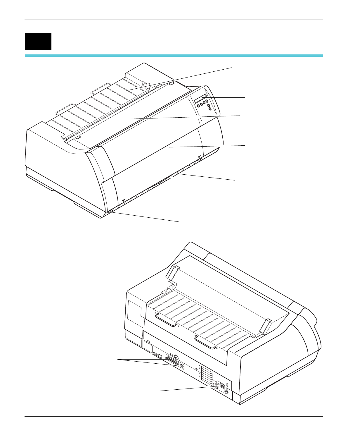
Printer at a glance
Rear cover
Control panel
Top cover
Front cover
Bottom cover
Interface connectors
Power cord connector and fuse
Power switch
3
Page 14
Printer at a glance User guide
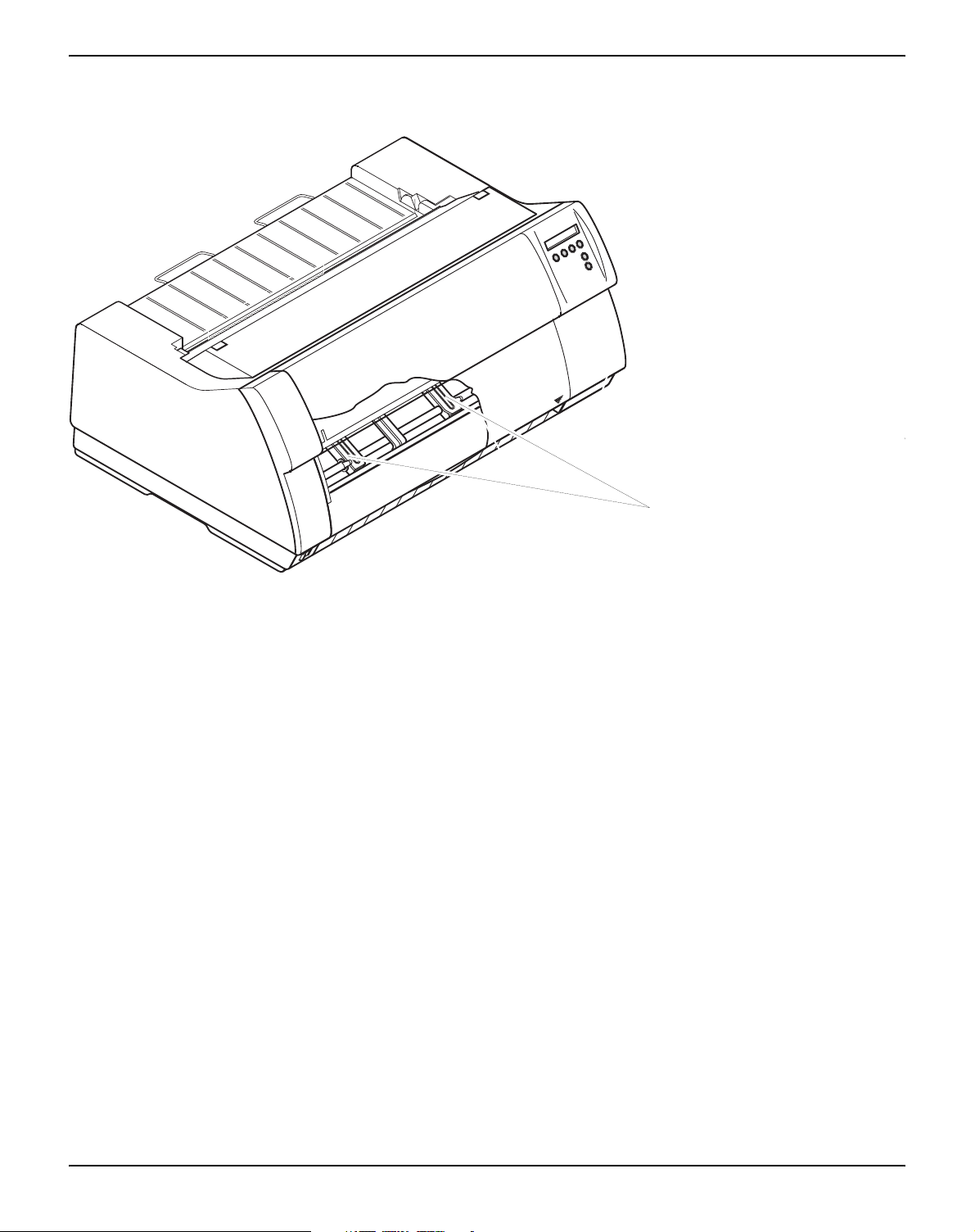
Printer in tractor mode
Tr ac to rs
4
Page 15
User guide Printer at a glance
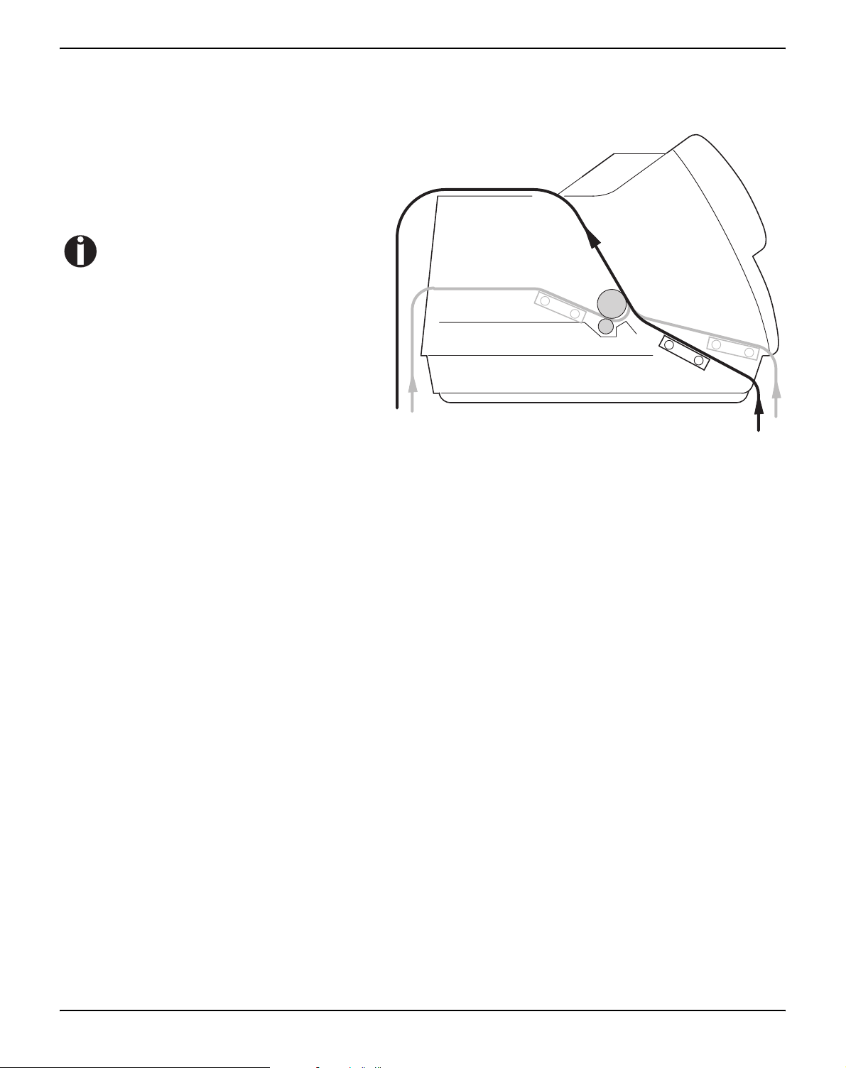
Paperway
Standard printer: Tractor 1
Options: Tractor 2
Tractor 3, only for
2T model, integrated
For additional paper options, please
contact your dealer.
Tractor 3
Tracto r 2
Tractor 1
5
Page 16

Page 17
User guide Installation
2
Installation
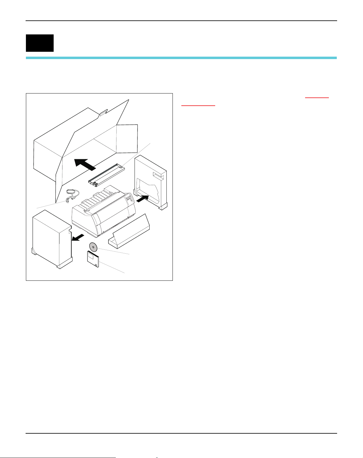
Unpacking the printer
e
f
Place your printer on a solid surface (see Placing
your printer, page 8).
Make sure that the “Up” symbols point in the correct
direction.
Open the packaging, take out the accessory cassette
and unpack it. Pull the printer out of the cardboard
box towards you and remove the remaining
packaging material.
Check the printer for any visible transport damage
and completeness. Apart from this CD-ROM (c) the
Quick start guide (d), the power cable (e) and the
ribbon (
If you find any transport damage or if any accessories
are missing, please contact your dealer.
f) must be included.
c
d
7
Page 18
Installation User guide
1
2
0
Placing your printer
Place the printer on a solid, flat, surface, ensuring
that the printer is positioned in such a way that it
can not topple, and that there is easy access to the
control panel and paper input devices. Also ensure that there is sufficient space for the printed
output.
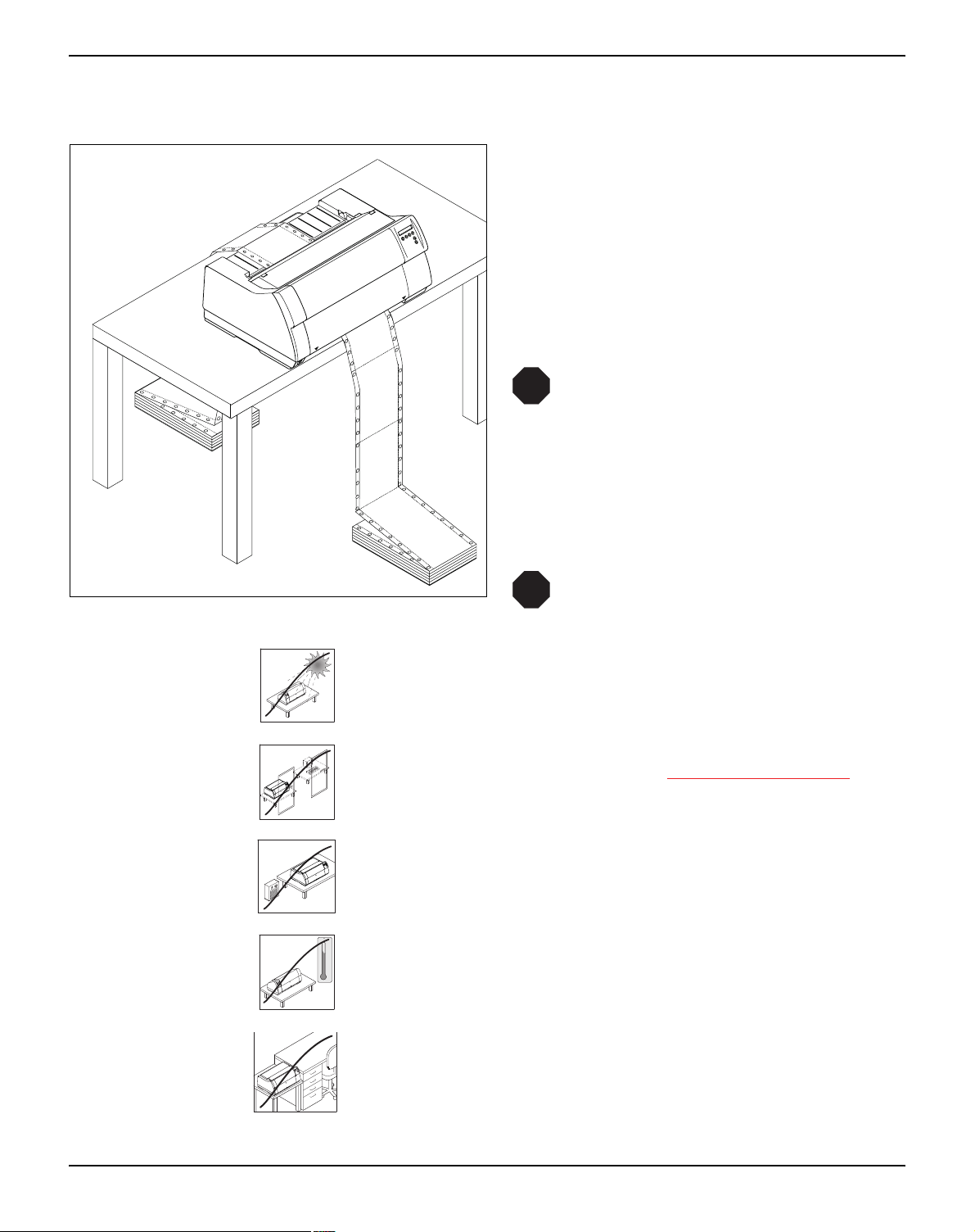
If you expect that frequent forward and reverse
feeds will occur, you should place the printer as
shown in the figure, if possible.
STOP
The power supply cable may be damaged if the paper edges constantly
chafe the insulating sheath. The user
must always ensure that there is sufficient distance between the power supply cable and the paper.
When selecting the printer location, observe the
following additional instructions:
STOP
Never place the printer in the vicinity of
inflammable gas or explosive substances.
Do not expose the printer to direct sunlight. If you cannot avoid placing the printer near a window, protect it from the sunlight with a curtain.
When connecting the computer with the printer, make sure not to exceed the permitted cable length (see Interface specifications
,
page 135).
Ensure sufficient distance between the printer and any heating radiators.
C
90
Avoid exposing the printer to extreme temperature or air humidity
80
70
60
50
40
30
20
10
fluctuations. Above all take care to avoid the influence of dust.
0
-10
It is recommended to install the printer in a place which is acoustically isolated from the workplace because of the noise it may
produce.
8
Page 19
User guide Installation
Checking the printer voltage
STOP
Make sure that the device has been set to the correct voltage (e.g.
230 V in Europe, 120 V in the USA). To do this, check the type plate
above the power inlet at the back of the printer. Contact your dealer
if the setting is incorrect.
Never switch on the printer if the voltage setting is incorrect,
since this may result in severe damage.
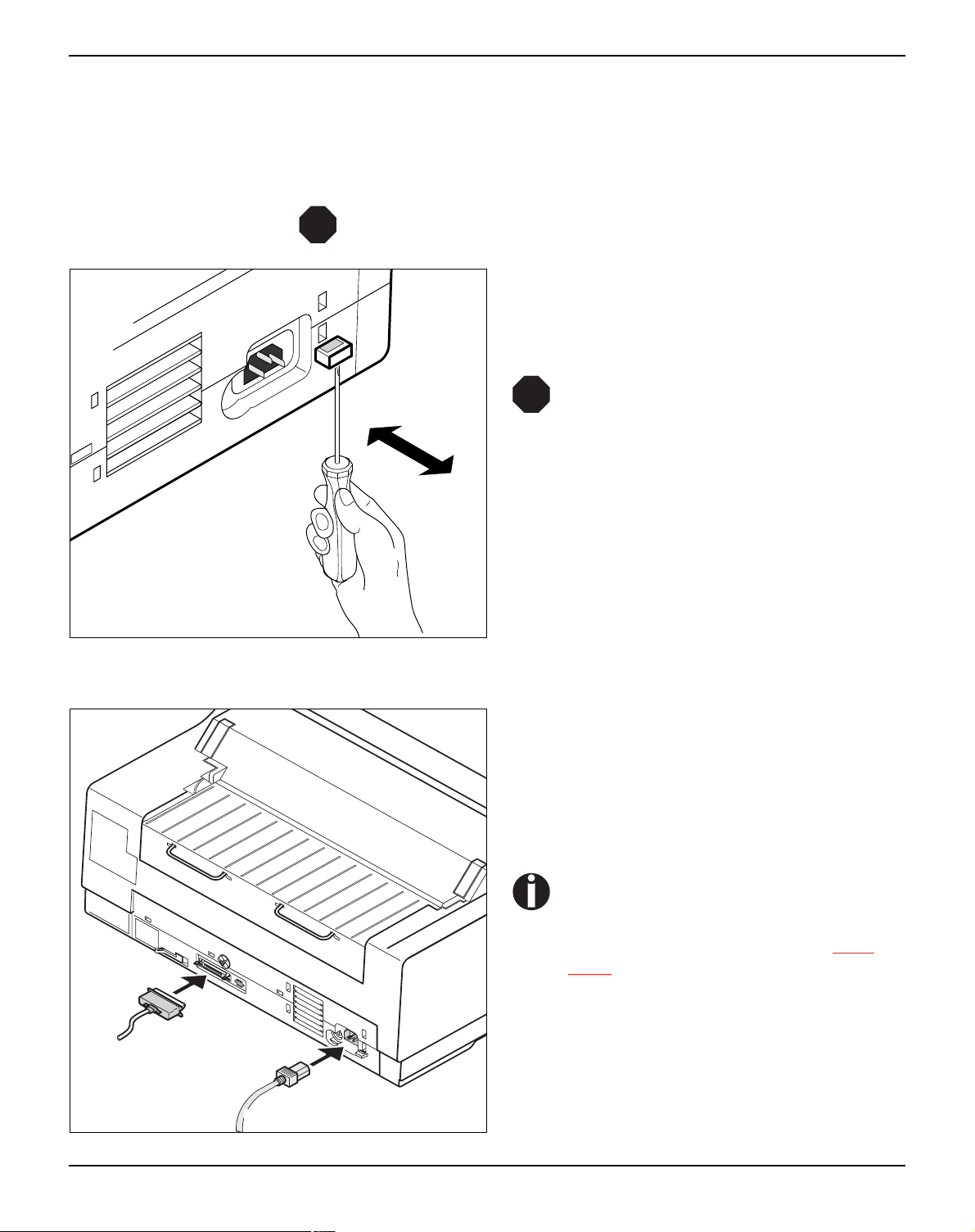
If the setting is incorrect, set the coloured switch at
the rear of the printer to the correct position, using
a pointed object (e.g. screwdriver, ball pen or
120V
tweezers).
STOP
Make sure that the printer is switched
off before setting the correct voltage;
otherwise severe damage may be
caused.
Connecting the printer
d
c
Connect the power cable c to the power inlet of
the printer. Connect the power cable plug to a
mains socket.
Make sure that the printer and the computer are
switched off and connect the data cable
tween the printer and the computer.
The printer by default is provided with a
parallel and an Ethernet interface. For
further information about the interfaces, refer to the section (see Inter-
faces, page 167).
d be-
9
Page 20
Installation User guide
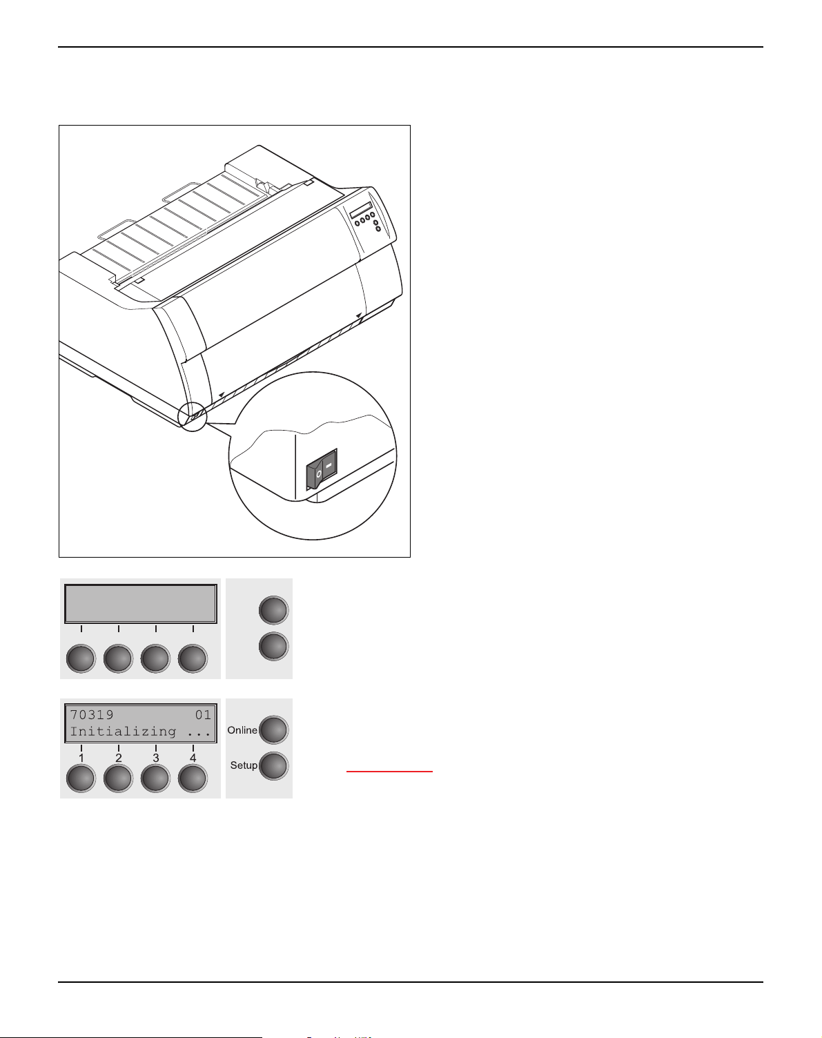
Switching on the printer
The power switch for switching on the printer is located at the bottom left at the front of the printer
when viewed from the front.
SDRAMTEST
20000 55AA ok
3
21
After switching on, the printer passes through a memory test during
Online
4
Setup
the initialization phase. In the display appears temporary the message "SDRAMTEST XXXXX XX ok".
If the memory test is successful finished, the firmware number appears in the display.
After finishing the initialization the printer switches to online mode
(see Online mode
, page 33).
10
Page 21
User guide Inserting the ribbon cassette
3
Inserting the ribbon cassette
Installing the ribbon cassette the first time
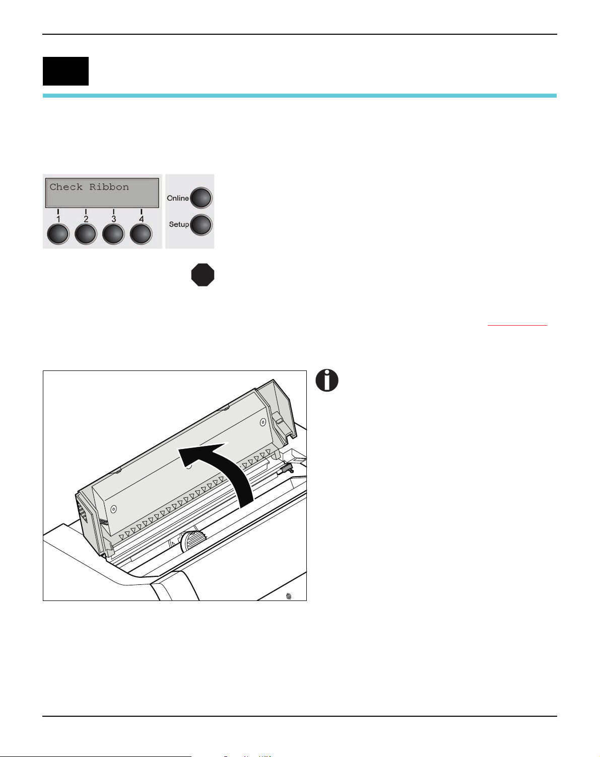
STOP
When delivered, no ribbon cassette is installed. When you switch on
the printer the first time, the printers display shows the message:
Now insert the supplied ribbon cassette.
During the process of initialization after powering on, the
printer checks if a ribbon cassette is installed. It also checks
during the execution of a print job the operativeness of the ribbon cassette. These functions mandatory require the use of
the manufacturers original ribbon cassettes (see Accessories
page 177). If other ribbon cassettes were used, the message
Check Ribbon appears in the display, it is impossible to print.
,
Before opening the cover, make sure
that the printer is switched on so that it
can execute automatic preparations for
ribbon changing (widening the print
head gap).
Open the printer top cover.
11
Page 22

Inserting the ribbon cassette User guide
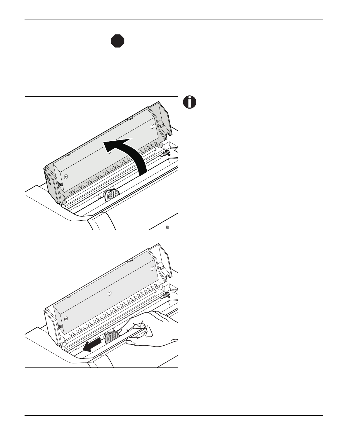
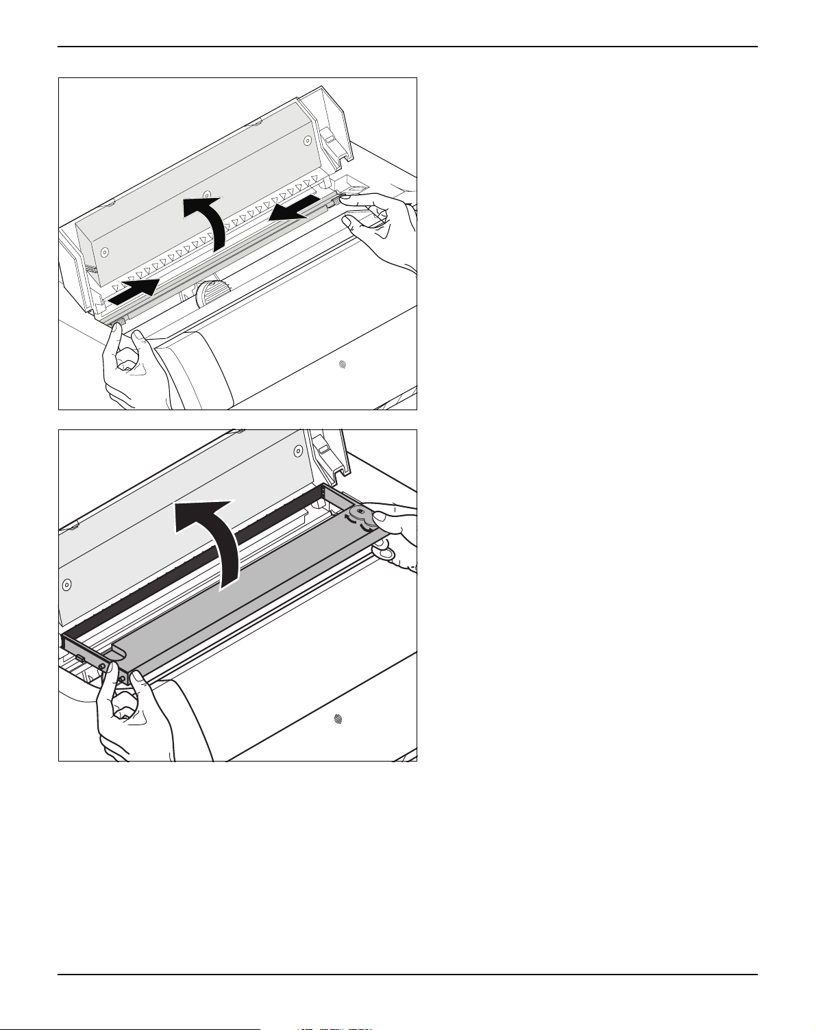
Cautiously slide the print head carriage to the left
stop (viewed from the printer front).
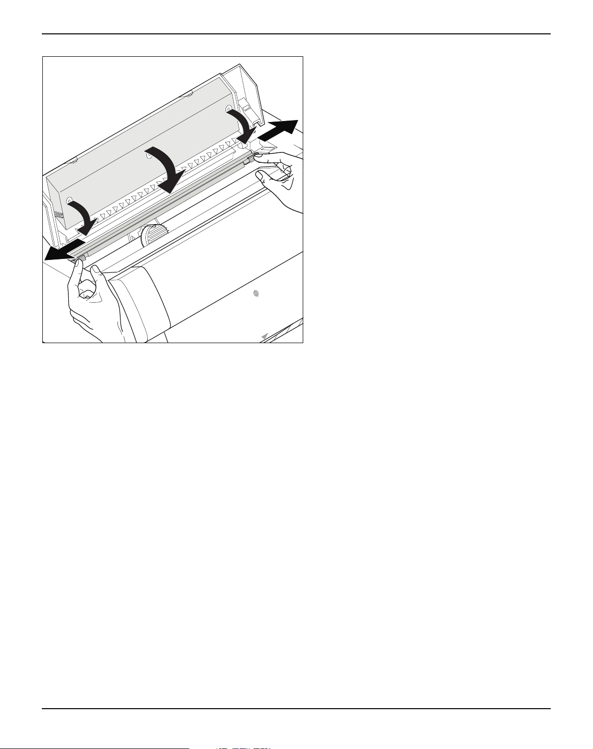
Move the coloured friction tabs to the left and right
(direction of the arrows) as shown in the figure and
raise the friction mechanism.
12
Page 23
User guide Inserting the ribbon cassette
A
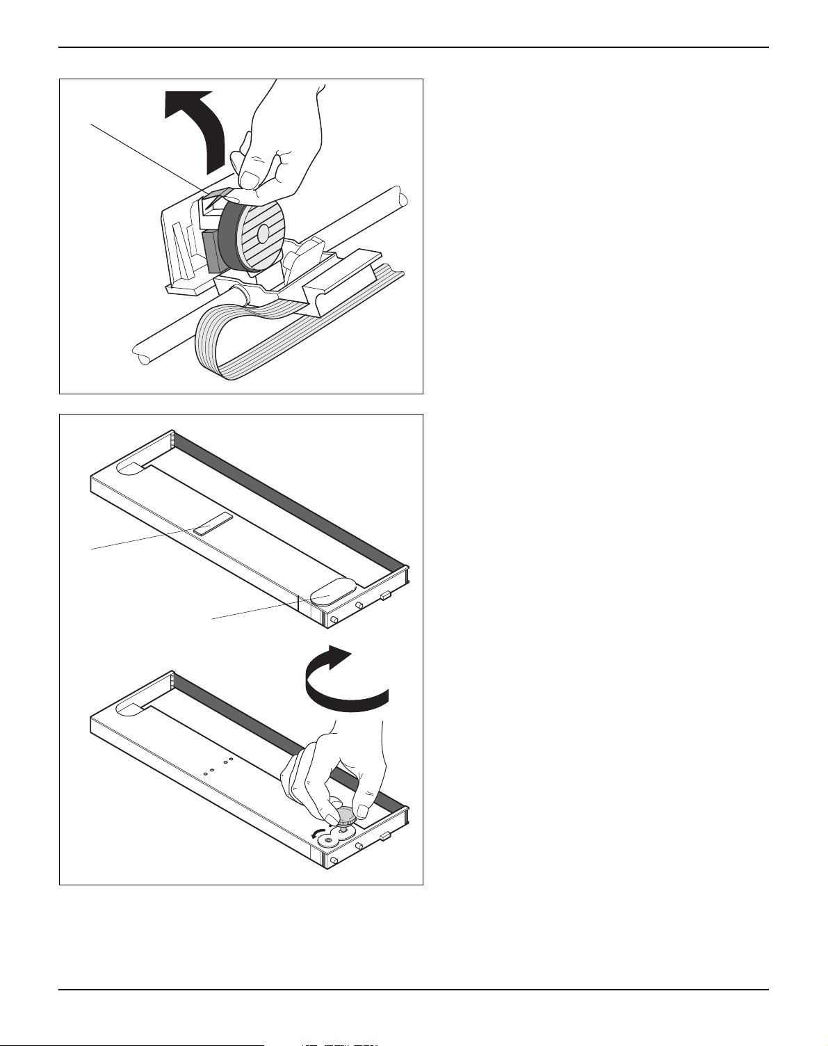
Raise the coloured insertion tongue A.
A
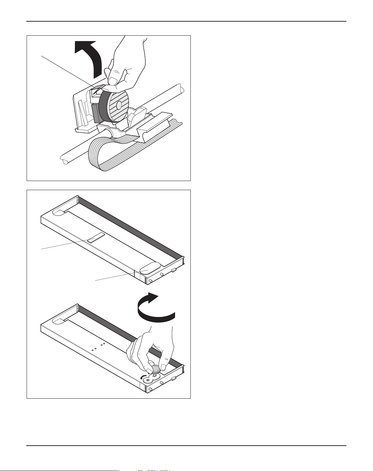
Remove the coloured protections A and B.
Insert the coloured ribbon tension knob into the
right-hand front location of the new ribbon cassette. Turn the knob in the direction of the arrow in
order to take up slack of the ribbon.
B
13
Page 24

Inserting the ribbon cassette User guide
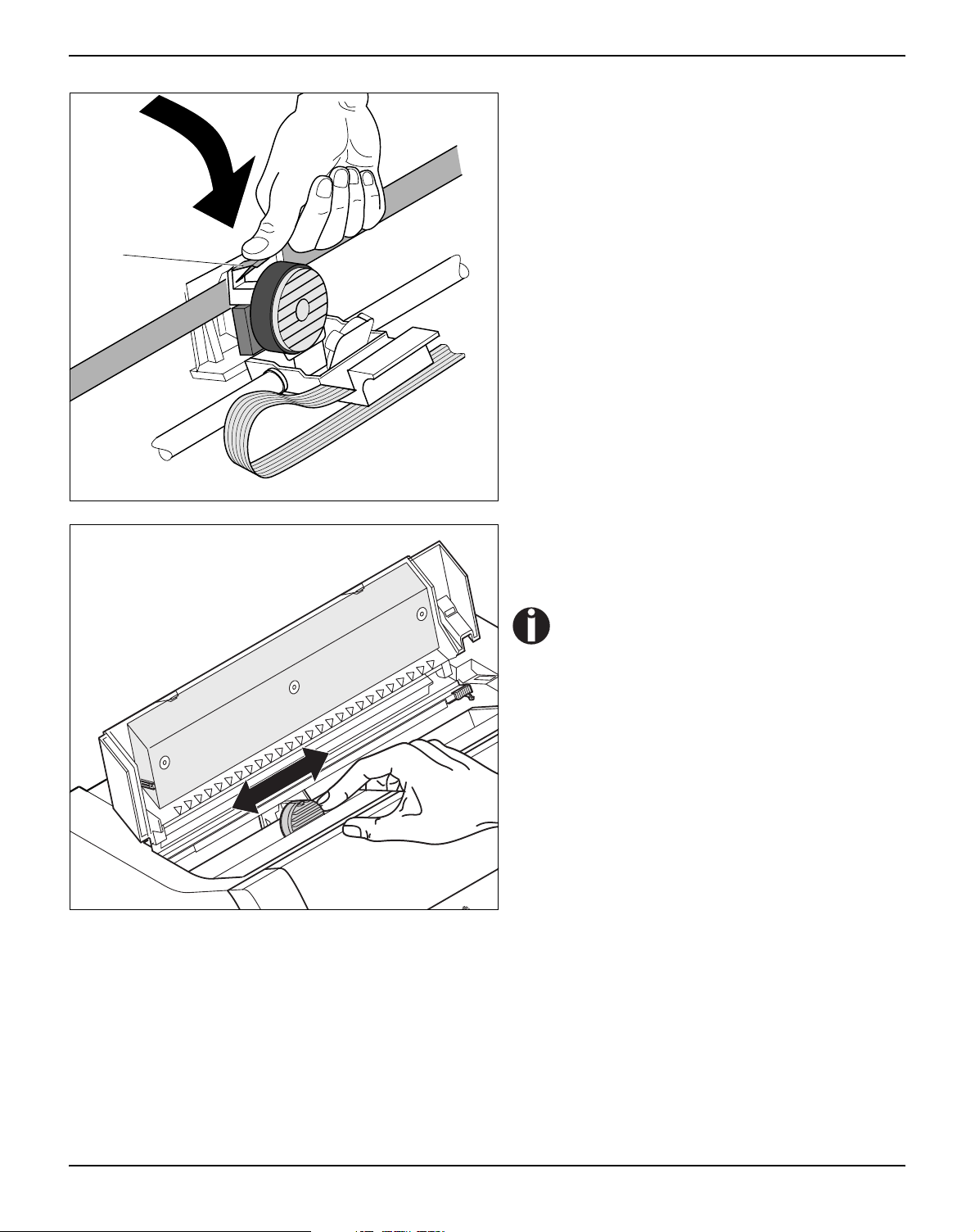
Slightly tilt the ribbon cassette forwards and thread
in the ribbon between the coloured insertion
tongue and the ribbon support (transparent plastic
plate).
Align and insert the cassette into the guides on the
left and right, then press down until it clicks into
place.
Insert the coloured tension knob into one of the
two locations.
Turn the tension knob in the direction of the arrow
to take up slack in the ribbon until it is seated correctly at the bottom in the ribbon support.
STOP
Remove the knob.
14
Page 25
User guide Inserting the ribbon cassette
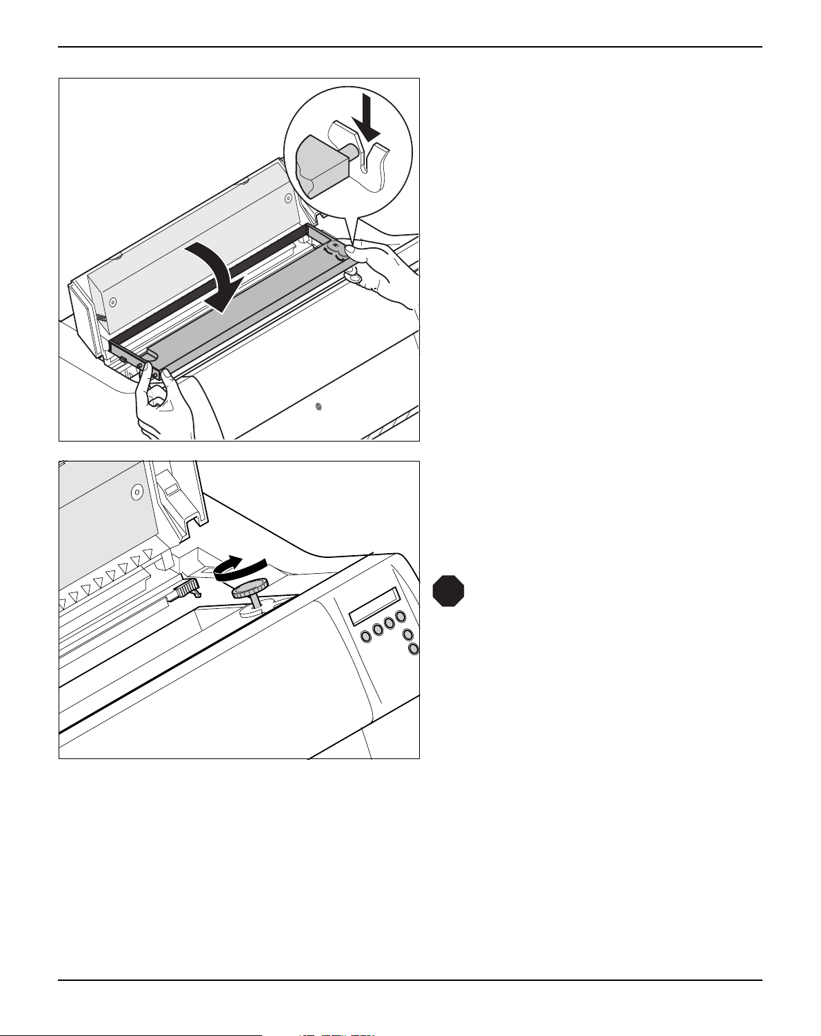
Press down the coloured insertion tongue A.
A
Move the print head carriage back and forth several times. If the ribbon is correctly seated, there
must be no perceptible resistance.
The ribbon should be transported during the travel from left to right. If this is
not the case, you should check that the
ribbon cassette is correctly inserted on
the right.
15
Page 26
Inserting the ribbon cassette User guide
Press the friction mechanism down until it clicks
into place.
Close the top cover.
16
Page 27
User guide Inserting the ribbon cassette
Changing the ribbon cassette
STOP
During the process of initialization after powering on, the
printer checks if a ribbon cassette is installed. It also checks
during the execution of a print job the operativeness of the ribbon cassette. These functions mandatory require the use of
the manufacturers original ribbon cassettes (see Accessories
page 177). If other ribbon cassettes were used, the message
Check Ribbon appears in the display, it is impossible to print.
Before opening the cover, make sure
that the printer is switched on so that it
can execute automatic preparations for
ribbon changing (widening the print
head gap).
Move the paper to the park position.
Open the printer top cover.
,
Cautiously slide the print head carriage to the left
stop (viewed from the printer front).
17
Page 28
Inserting the ribbon cassette User guide
Move the coloured friction tabs to the left and right
(direction of the arrows) as shown in the figure and
raise the friction mechanism.
Remove the used cassette.
18
Page 29
User guide Inserting the ribbon cassette
A
Raise the coloured insertion tongue A.
A
Remove the coloured protections A and B.
Insert the coloured ribbon tension knob into the
right-hand front location of the new ribbon cassette. Turn the knob in the direction of the arrow in
order to take up slack of the ribbon.
B
19
Page 30
Inserting the ribbon cassette User guide
Slightly tilt the ribbon cassette forwards and thread
in the ribbon between the coloured insertion
tongue and the ribbon support (transparent plastic
plate).
Align and insert the cassette into the guides on the
left and right, then press down until it clicks into
place.
Insert the coloured tension knob into one of the
two locations.
Turn the tension knob in the direction of the arrow
to take up slack in the ribbon until it is seated correctly at the bottom in the ribbon support.
STOP
Remove the knob.
20
Page 31

User guide Inserting the ribbon cassette
Press down the coloured insertion tongue A.
A
Move the print head carriage back and forth several times. If the ribbon is correctly seated, there
must be no perceptible resistance.
The ribbon should be transported during the travel from left to right. If this is
not the case, you should check that the
ribbon cassette is correctly inserted on
the right.
21
Page 32

Inserting the ribbon cassette User guide
Press the friction mechanism down until it clicks
into place.
Close the top cover.
22
Page 33

User guide Printer drivers
4
Printer drivers
You need to install a printer driver so that the printer can process the
data from your application programs.
An original driver offers the best conditions for optimal printing results. All available printer drivers can be found on the CD-ROM enclosed with the printer, as well as on our Internet
can also download updated versions as necessary.
Installing a printer driver in Windows 95/98/ME
In this operating system the compatible 2365 and 2380 driver
can be used.
Installing a printer driver in Windows 2000/2003/XP
The online CD-ROM contains printer drivers for the most common
Windows applications. To install the printer driver, proceed as follows.
site, from which you
1 Insert the supplied online CD-ROM in the CD-ROM drive.
2 Click on the Start button in the Windows taskbar.
3 Click on Printers and Faxes to open the printer folder.
4 Click on File and Add Printer in the menu bar.
5 Click on Next In the Printer Installation Wizard.
6 Specify whether you want to operate the printer as a Local Printer
or Network Printer by clicking on the relevant option, then press
Next.
For instructions on installing the printer as a network printer,
please consult the documentation supplied with your network
operating system and/or printer server, or contact the network
administrator.
To install a network printer, you will need Administrator rights.
If you are using the printer locally, you can continue installing the
driver in one of two possible ways:
` Manual installation of printer driver: in this case, continue with
Step 7.
` Automatic installation of printer driver via Plug & Play function: in this
case, continue with Step 12 once the printer installation wizard has
determined the printer, port and printer name.
23
Page 34

Printer drivers User guide
Then click on Next.
7 Select the port to which your printer is connected, then click on Next.
8 Click on Data Carrier, then click on Browse.
9 Select the CD-ROM drive and open the directory n:\driver (“n“
stands for the letter of your PC drive).
10 Open the folder 32Bit or 64Bit.
11 Select the printer type and then click on Next.
12 If required, edit the name of the default printer and specify whether
you wish to use the printer as a default printer by clicking on the relevant option. Then click on Next.
13 If you are using the printer as a network printer, you have the option
of sharing it with other network users. In this case you must enter an
access name which will be displayed to the other network users.
Then click on Next.
14 Specify whether you wish to print out a test page (recommended) by
selecting the relevant option and click on Finish. The printer driver
will now be installed.
24
Page 35

User guide Printer drivers
Installing a printer driver in Windows 7
The online CD-ROM contains printer drivers for the most common
Windows applications. To install the printer driver, proceed as follows.
1 Insert the supplied online CD-ROM in the CD-ROM drive.
2 Click on the Start button in the Windows taskbar.
3 Click on Devices and Printers to open the printer folder.
4 Click on Add a Printer in the menu bar.
5 Specify whether you want to operate the printer as a Local Printer
or Network, wireless or Bluetooth printer by clicking on the rele-
vant option, then press Next.
For instructions on installing the printer as a network printer,
please consult the documentation supplied with your network
operating system and/or printer server, or contact the network
administrator.
To install a network printer, you will need Administrator rights.
If you are using the printer locally, you can continue installing the
driver in one of two possible ways:
` Manual installation of printer driver: in this case, continue with
Step 6.
` Automatic installation of printer driver via Plug & Play function: in this
case, continue with Step 11 once the printer installation wizard has
determined the printer, port and printer name.
6 Select the port to which your printer is connected, then click on Next.
7 Click on Have Disk, then click on Browse.
8 Select the CD-ROM drive and open the directory n:\driver (“n“
stands for the letter of your PC drive).
9 Open the folder 32Bit or 64Bit.
10 Select the printer type and then click on Next.
11 If you are using the printer as a network printer, you have the option
of sharing it with other network users. In this case you must enter an
access name which will be displayed to the other network users.
Then click on Next.
12 If required, edit the name of the default printer and specify whether
you wish to use the printer as a default printer by clicking on the relevant option. Then click on Next.
13 Specify whether you wish to print out a test page (recommended) by
selecting the relevant option and click on Finish. The printer driver
will now be installed.
25
Page 36

Printer drivers User guide
Installing a printer driver in Windows Vista
The online CD-ROM contains printer drivers for the most common
Windows applications. To install the printer driver, proceed as follows.
1 Insert the supplied online CD-ROM in the CD-ROM drive.
2 Click on the Start button in the Windows taskbar.
3 Click on All Programs.
4 Click on Devices and Printers to open the printer folder.
5 Click on Printers in the menu window.
6 Click on Add a Printer in the menu bar.
7 Specify whether you want to operate the printer as a Local Printer
or Network, wireless or Bluetooth printer by clicking on the rele-
vant option, then press Next.
For instructions on installing the printer as a network printer,
please consult the documentation supplied with your network
operating system and/or printer server, or contact the network
administrator.
To install a network printer, you will need Administrator rights.
If you are using the printer locally, you can continue installing the
driver in one of two possible ways:
` Manual installation of printer driver: in this case, continue with
Step 8.
` Automatic installation of printer driver via Plug & Play function: in this
case, continue with Step 13 once the printer installation wizard has
determined the printer, port and printer name.
8 Select the port to which your printer is connected, then click on Next.
9 Click on Have Disk, then click on Browse.
10 Select the CD-ROM drive and open the directory n:\driver (“n“
stands for the letter of your PC drive).
11 Open the folder 32Bit or 64Bit.
12 Select the printer type and then click on Next.
13 If you are using the printer as a network printer, you have the option
of sharing it with other network users. In this case you must enter an
access name which will be displayed to the other network users.
Then click on Next.
14 If required, edit the name of the default printer and specify whether
you wish to use the printer as a default printer by clicking on the relevant option. Then click on Next.
26
Page 37

User guide Printer drivers
15 Specify whether you wish to print out a test page (recommended) by
selecting the relevant option and click on Finish. The printer driver
will now be installed.
Other operating systems
The printer can also be used with other operating systems such as
Linux or Unix. In this case, set the printer to one of the Epson emulations (LQ-2550/LQ-2170) or IBM emulations (Proprinter XL 24e/
Proprinter XL 24e + AGM) for which default drivers are available in
most operating systems.
27
Page 38

Printer drivers User guide
Changing printer settings
Form settings (Windows 2000/2003/XP/ Vista/Windows 7/2008)
You can make permanent changes to the printer settings using the
control panel of the printer (see The Menu
settings can also be entered in the operating system of your PC,
however.
1 Click on the Start button in the Windows taskbar.
2 Windows 95/98/ME: move the mouse to Settings and click on Print-
ers to open the printer folder.
Windows 2000/2003/XP: click on Printers and Faxes to open the
printer folder.
3 Move the mouse pointer to the appropriate printer symbol, press the
right mouse key and click on Properties.
Details of the settings available in this window can be found in the
Windows documentation or help pages.
Settings entered in the printer driver via Windows have priority
over settings entered via the printer menu. It is therefore possible that the former may overwrite the latter.
In contrast to Windows versions 95/98/ME, in which forms are defined in the printer driver itself, Windows versions 2000/2003/XP/
Vista/Windows 7/2008 have a central facility for managing form
properties and assign one paper feed only.
, page 55). Various printer
If you want to set up a form not included in the Windows default settings, proceed as follows.
You will need Administrator rights to define new forms.
1 Click on the Start button in the Windows taskbar.
2 Click on Printers and Faxes to open the printer folder.
3 In the menu bar, click on File and Server Properties.
4 In the window Printer Server Properties, click on Form if neces-
sary.
5 Either select an existing form from the Forms list or activate the op-
tion New Form.
6 Enter a form name and the desired values.
7 Click on Save to save the new form.
You can now assign this form to the paper feeds of your printer (see
Changing printer settings
The form cannot be assigned if its dimensions exceed the permissible paper sizes of the specified paper feed.
, page 28).
28
Page 39

User guide Printer drivers
Loading optional firmware
3
21
BOOT
21
4
3
4
Online
Setup
Online
Setup
STOP
If you download new firmware as described below, all menu
settings except the settings for the transmission speed of the
Ethernet interface and the IP address administration will be
overwritten. For this reason you should print a menu dump in
or to be able to reestablish the previous settings if necessary
(see Printing out menu configurations (Print)
, page 61).
To load new firmware, proceed as follows.
The most current version of the firmware can be downloaded
from our internet
page.
1 Switch off the printer. Connect your DOS PC (LPT1:) to the par-
allel port on the printer.
2 Press keys 1, 4 and Online. Hold the keys pressed.
3 Switch on your printer.
The printer is ready for the download when BOOT appears on its
display.
4 In Windows open the MS-DOS window.
5 Copy the file, e.g. DOWNLOAD.FDF, to your printer:
COPY /B X:\path\DOWNLOAD.FDF PRN
(X:\path stands for the drive and the directory in which the file is located.)
Download
firmware
3
21
Online
4
Setup
on the display during the download; alternatively, an error message
is displayed:
PRG = Firmware
GEN = Character set or font (character generator)
P+G = Firmware and character set
BOO = Firmware, character set and boot block
The number of the currently transferred data block (frame) is displayed in addition in the top line of the display on the right.
DOWNLOAD OK and BOOTAREA SKIPPED is displayed briefly
when the procedure has been completed successfully. The printer
then runs through its initialisation routine, after which it is ready for
use.
Troubleshooting It is necessary to repeat the entire procedure if an error occurs dur-
ing the download. This is indicated by a corresponding message on
the display. It may be that not all fault messages can be shown on
the display. In this case, the operating system of your PC displays
an error message such as “Write error on device”.
A progress indicator (bar) and DOWNLOAD FIRMWARE appears
29
Page 40

Page 41

User guide The control panel
5
The control panel
The control panel keys are used for controlling your work with the
printer. The control panel is located on the front right side of your
printer and consists of a two-line liquid crystal display and six keys.
The functions of the keys depend on the printer’s current mode (status). There are four basic modes.
` The Online mode is the printer’s normal operating mode. Data from
your computer can be received and printed.
` In the Offline mode the link between printer and computer is inter-
rupted, i.e. no data can be received and printed.
` In the Setup mode you can either select the printer menu or carry
out the so-called quick-switch function. The quick-switch option was
included so that you can change the most important parameters (for
example adjustments, character density, font, paper path, adjustments i.e. head gap) directly without having to enter them via the
menu. The settings for the parameters character density and font
are lost when the printer is switched off. They can be selected permanently in the menu mode of the printer.
` In the Menu mode further printer settings (line spacing, size of the
interface buffer etc.) can be altered and saved permanently.
31
Page 42

The control panel User guide
The LC display The LC display tells you all the important printer settings and informs
you which functions are currently assigned to which keys.
The upper line informs you that the printer is either in online or offline
mode (in the example below the printer is in the Online mode), and
the selected paperpath (below: Trac1 = Tractor 1 = tractor mode,
key 4 is currently activating the manual tear).
Example:
Key functions
Printer status
Online Trac1
Paper path
Tear
21
3
4
Online
Setup
32
Page 43

User guide The control panel
Online mode After switching on, the printer is automatically set to online mode.
Only in this mode can it receive data from the computer.
Online Trac1
Tear
3
21
4
Online
Setup
loaded, see Moving the paper to the tear position
If Load is displayed above this key, no paper is loaded in the
printer or the printer is in park position. In this case the display
switches between Online and Load paper fromTrac1. Press the
(page 43).
key to feed paper to the printing position.
` Setup key: Sets the printer to setup mode.
` Online key: Sets the printer to offline mode.
Offline mode Only in this mode is it possible to perform step, line, or form feeds
` Tear key (4): Activates the tear function when fanfold paper is
from the control panel, see Paper transport
data cannot be received.
` Park key (1): Clears the paper path with paper loaded and acti-
vates paper path quick selection.
` Key (2): Short keypress: Microstep forward. Long keypress:
Continuous paper feed.
` Key (3): Short keypress: Microstep reverse. Long keypress:
Continuous paper reverse feed up to the park position.
(page 42); however,
` Load key (4): Displays that no paper is loaded in the printer or the
printer is in park position. In this case the display switches between Online and Load paper fromTrac1.
If paper is loaded: Loads paper from the selected paper source;
the display changes to LF/FF
Short keypress: Line Feed (LF).
Long keypress: Form Feed (FF).
` Setup key: Sets the printer to setup mode.
` Online key: Sets the printer to online mode.
33
Page 44

The control panel User guide
Setup mode In this mode, the following settings are available:
Adjust Paperway
Menu Char
3
21
4
Online
Setup
` Setup key: Sets the printer to setup mode, in which the following
settings can be selected:
` Menu key (1): Other menu settings. Access may be disabled by
the manufacturer (see note below).
` Adjust key (2): Sets the Tear position, first printing line and print
head gap.
` Paperway key (3): Sets the Paper path.
` Char key (4): Sets the font and the number of characters per
inch.
Access to the other menu settings (Menu) may be disabled by
the manufacturer.
Proceed as follows to release this lock temporarily:
Hold depressed the Setup key or the Menu key (1) for five seconds.
Or:
1 Switch off the printer for approx. 5 seconds.
2 Switch the printer on again keeping the Setup key pressed.
For information on how to enable access permanently and
about the available settings, refer to the section Menu lock
(MenLock) (page 80) and Menu parameters (page 61).
34
Page 45

User guide The control panel
Messages in the LC display
If the printer detects an internal fault or user error or if it expects you
to do something, a message will appear in the LC display. It also displays the status during an operation (e.g. Initializing). Below you
will find a list of messages with brief descriptions of each message.
The messages are described in greater detail in the chapter Error
messages via the display (page 122).
Message Meaning
Eject error The printer cannot eject the paper/
advance it to park position.
Hardware Alarm Internal hardware error. Try power
cycling the printer. If the message
appears again, contact your dealer or
service technician.
Initializing This message appears during the
printer’s initializing phase after switching on the printer.
Load error The printer cannot draw in the loaded
paper.
Load paper from The printer has detected paper end
during operation/printer was switched
on with no paper loaded.
Loading default Factory defined parameters will be
reloaded in all available menus after
switching on the printer.
Out of paper The printer has detected paper end
during operation / printer was switched
on with no paper loaded.
Paperwidth error Print characters override the detected
right paper margin.
Parity error A parity error during data transmission
is indicated.
Park position Paper is not being fed into print posi-
tion.
Press any key The user is requested to press any
key.
PW sensor defect The automatic paper width detection
cannot detect the left paper margin.
Selftest After power-on, the printer executes a
short hardware self-test.
35
Page 46

The control panel User guide
Message Meaning
Tear Paper off The user is requested to tear off paper
which has been advanced to the tear
edge.
AED Error AED sensor cannot locate paper trans-
port holes (only if a cut device is
installed).
36
Page 47

User guide The control panel
Key functions when turning on the printer
If you keep one of the following keys pressed during power-on until
the printer has completed initialisation, the corresponding function is
activated:
` If you keep the Online key depressed while turning on the printer,
you enter the printer’s advanced menu mode. The advanced menu
mode is described in the section Advanced menu
manual.
` If you keep the Setup key depressed while turning on the printer,
you regain access to the printer menu if you had locked it before with
the help of the MenLock function. The MenLock function is de-
scribed in the section Menu lock (MenLock)
` If the four function and select keys (keys 1 to 4) are depressed si-
multaneously while turning on the power, all printer settings are reset to the default values, except the Forml (Form length) and Single
setting in advanced menu mode.
This causes all the user’s previous settings to be lost.
(page 95) of this
(page 80).
37
Page 48

Page 49

User guide Paper handling
6
Paper handling
This section describes how to load fanfold paper, transport paper
and move the paper to the tear position.
Loading paper Your printer can process fanfold paper. For informations on allow-
able paper formats, refer to the section Paper specifications
(page 136).
Only use dust-free or low-dust paper. Many paper qualities are
suitable for this printer. For more information, please refer to
the section Paper specifications
Open the front cover.
Remove the bottom cover A.
Open the right and left tractor flaps.
(page 136).
A
39
Page 50

Paper handling User guide
Release the coloured latch lever of the lefthand tractor and align the tractor so that the
first printing position on the paper matches the
X mark on the printer housing.
Lock the coloured lever again.
Place fanfold paper into the left-hand tractor.
Open the coloured latch lever of the right-hand
tractor and align it to the paper width.
Insert the fanfold paper into the right-hand tractor.
Make sure that it is inserted by the same length
as on the left-hand tractor in order to avoid any
paper jam.
Close the tractor flap and lock the tractor by
turning the tractor lever to the rear.
Do not tension the paper excessively
to avoid tearing the perforation holes;
do not allow excessive slack since in
this case the paper will bulge and
there may be problems in the feeding
process.
40
Page 51

User guide Paper handling
Make sure to align the paper stack in parallel
with the printer and that the paper flow is unobstructed.
90
Lower the front cover.
Switch the printer on. The active paper source (Tractor1) appears
in the display. The display alternates between…
and …
The paper is automatically loaded when the printer is in online mode
and receives data from the computer.
Press the Load (4) key only to load paper before starting the
printout. However it is recommended to let the receiving data
load the paper.
41
Page 52

Paper handling User guide
Paper transport Loaded paper can be transported in the printer in several ways.
Offline Trac1
Park LF/FF
3
21
4
Online
Setup
Make sure that the printer is in offline mode; press the Online key,
if necessary.
` Key Park (1)
If fanfold paper is loaded in the printer, it is fed to the park position
or the tear position.
` Key (2)
Short keypress: Paper is transported upwards step by step.
Long keypress: Continuous transport upwards.
` Key (3)
Short keypress: Paper is transported downwards step by step.
Long keypress: Continuous transport downwards.
` LF/FF key (4):
Short keypress: Line Feed (LF) is executed.
Long keypress: Form Feed (FF) is executed.
The maximum value of the paper return feed is 22 inches.
42
Page 53

User guide Paper handling
Moving the paper to the tear position
Online Trac1
Tear
3
21
Tear position
Trac1
3
21
Online Tear
Exit
3
21
Online
4
Setup
Online
4
Setup
Online
4
Setup
You can use the Tear key to move the paper to the tear position. The
tear edge is located at the front side of the paper output opening.
Make sure that the printer is in online mode. If necessary, press the
Online key.
Press the Tear (4) key. The printer moves the perforation edge of
the fanfold paper to the tear edge. The tear edge is located at the
front side of the paper output opening (see below).
The display alternates between…
and…
A
Online Tear
Exit
3
21
4
Online
Setup
Tear off paper at the tear edge A.
Make sure you tear the paper off
straight, otherwise a paper jam may
occur.
After having torn off the paper, press the Exit (4) key. The printer re-
turns the paper to the first printing position.
If a print job is active, the printer returns the paper automatically to
the next printing position.
43
Page 54

Paper handling User guide
Removing paper Never use force to remove the paper from the printer. Other-
STOP
wise the mechanical components may be damaged.
Make sure that the printer is in offline mode; press the Online key,
if necessary.
Press the Park (1) key. If fanfold paper is loaded in the printer, it is
fed to the tear position. The text Tear paper off appears in the dis-
play.
Now remove the paper from the tractor. Then press any key.
44
Page 55

User guide Settings
7
Settings
Setting the print head gap
Adjust Paperway
Menu Char
3
21
TOF
Head Tear
Online
4
Setup
Online
This section describes how to set the tear position, the first printing
line, the print head gap as well as the font and the character density.
The printer features automatic print head gap adjustment to the
thickness of the paper used. In setup mode, you can enter a correction value to modify the head gap determined automatically. This
correction is useful for modifying the appearance of the type face.
The AGA (automatic gap adjustment) function must be set to
On. For more detailed information, refer to the section Automa-
tic gap adjustment (AGA) (page 103).
Press the Setup key. The printer changes to setup mode.
Press the Adjust (2) key.
Press the Head (1) key.
3
21
Head= 0 *
Set < > Exit
21
4
3
4
Setup
Online
Setup
Use the < (2) or > (3) key to set the range within which the automatic
gap adjustment is to be corrected. You can select values in the
range from -10 to +10.
Confirm the input by pressing the Set (1) key.
Press the Setup key. The printer returns to the initial status.
Negative values decrease the print head gap, positive values
increase it. Changing the automatically determined value may
have a strong effect on the printing quality.
The setting made will be retained after switching off the
printer.
If the printout shows signs of smudging, we recommend that
you increase the print head gap up to +10 (if AGA is on, see
Automatic gap adjustment (AGA)
(page 103)) and use a less
smooth type of paper.
45
Page 56

Settings User guide
Setting the tear position
Adjust Paperway
Menu Char
3
21
TOF
Head Tear
21
TearAdj= 00/72"*
Set < > Exit
21
4
3
4
3
4
Online
Setup
Online
Setup
Online
Setup
If the tear position of the paper is not aligned with the tear edge of
the printer, you can adjust it. Inserted paper needs to be torn off if
necessary and retracted to park position.
Press the Setup key. The printer changes to setup mode.
Press the Adjust (2) key.
Press the Tear (4) key.
Press the < (2) or > (3) key to move the perforation to the desired
position. Confirm the input by pressing the Set (1) key. Confirm the
input again by pressing the Setup key. The printer is reset to the initial status.
The correction made – a maximum of approx. 1" (2.5 cm) in
each direction – will be retained after switching the printer off.
It can be set separately for each paper path.
Make sure that the set form length corresponds to the actual
length of the forms you are using.
46
Page 57

User guide Settings
Setting the first printing line (TOF)
Adjust Paperway
Menu Char
3
21
TOF
Head Tear
3
21
B
A
Online
4
Setup
Online
4
Setup
You can use the TOF function for setting the position of the first printing line for each paper source and each menu individually.
Before using the TOF function, you should first set the tear
position; see Setting the tear position
(page 46).
Press the Setup key. The printer changes to setup mode.
Press the Adjust (2) key.
Press the TOF (3) key.
The paper is fed to the position where the bottom edge of the first printing line A is aligned
with the tear edge B of the printer. The factory
setting for the first printing position (TOF) is
12/ 72" (4,23 mm/1/6 inch). This is equivalent to
the second line from the top.
Computerdrucker
FormAdj= 12/72"*
Set < > Exit
3
21
4
Online
Setup
Press the < (2) or > (3) key to move the first printing line to the desired position. You can set values from 0 to 220/72" for fanfold paper.
Confirm the input by pressing the Set (1) key. Press the Setup key.
The printer returns to the initial status.
The selection made will be retained after switching off the
printer.
47
Page 58

Settings User guide
Selecting character density and font
Adjust Paperway
Menu Char
3
21
Font CPI
3
21
10 CPI *
Set < > Exit
3
21
Online
4
Setup
Online
4
Setup
Online
4
Setup
You can use the CPI (Character Per Inch) key in setup mode to se-
lect the number of characters per inch to be printed. You can use the
Font key to select resident fonts.
Press the Setup key, then the Char (4) key.
Press the CPI (3) or Font (2) key (in our example, press CPI).
Use the < (2) or > (3) key to set the desired character density. Confirm the selection by pressing the Set (1) key.
You can cancel the selection and leave the setting unchanged by
pressing the Exit (4) key.
ROMAN NLQ
Set < > Exit
3
21
4
Adjust Paperway
Menu Char
3
21
4
Online
Setup
Online
Setup
If you pressed the Font (2) key, use the < (2) or > (3) key to select
the desired font. Confirm the selection by pressing the Set (1) key.
You can cancel the selection and leave the setting unchanged by
pressing the Exit (4) key.
Press the Setup key. The printer returns to the initial status.
It is also possible to press the Online key. The printer then changes
directly to online mode.
The selection made will not be retained after switching off the
printer. For more details on how to set the character density
and fonts permanently, please refer to the chapter Setting cha-
racter density (CPI) (page 64) and Selecting font (Font) (page 63).
48
Page 59

User guide 2T model
8
2T model
Introduction This section describes how to handle the rear tractor (paper feed
from the rear), which is only available and permanently installed in
the 2T printer model in addition to the primary tractor (paper feed
from the front).
The Paperway parameter group in the menu of the 2T model differs
from the one of the standard printer as follows:
Standard printer 2T printer
Paperway
Tractor1 (standard, front)
Tractor2 (optional, front)
The permanently installed rear tractor is identified as “Trac3”
in the menu. “Trac2“ in the menu refers to the optional tractor
which can be installed both on the standard printer and the 2T
model. The optional tractor 2 can be installed by the user.
Paperway
Tractor1 (standard, front)
Tractor2 (optional, front)
Tractor3 (standard, rear)
Rear tractor paper path
Tractor 3
Tracto r 2
Tractor 1
For information on the printable length and width of the forms
and other specifications, refer to Paper specifications
The 2T model cannot accommodate an additional automatic
single sheet feeder, which is available for some printer models.
, page 136.
49
Page 60

2T model User guide
Loading paper into the rear tractor
To place fanfold paper into the rear tractor, proceed as follows.
Raise the rear cover vertically and remove it.
Open both the right-hand and left-hand tractor
flaps.
50
Release the coloured latch lever of the lefthand tractor and align the tractor in such a way
that the first printing position on the paper
matches the X mark on the printer housing.
Then fix the coloured lever again. Insert fanfold
paper into the left-hand tractor.
Page 61

User guide 2T model
Release the coloured latch lever of the righthand tractor and align it to the paper width. Insert the fanfold paper into the right-hand tractor. Make sure that the paper form is inserted
straight in order to avoid any paper jam. Close
the tractor flap and lock the tractor by turning
the lever towards the rear.
Do not tension the paper excessively
to avoid tearing the perforation holes;
do not allow excessive slack since in
this case the paper will bulge and
there may be problems in the feeding
process.
Make sure to align the paper stack in parallel
with the printer and that the paper flow is unobstructed.
Reinsert the rear cover vertically and lower it towards the rear.
Slide the cover towards the rear to the stop; this
will leave a slot for the paper.
Switch the printer on. It will perform a self-test
and then go to online mode.
Paper may remain inserted in the front and rear tractors at the
same time. This is made possible by moving the paper in the
inactive tractor automatically to the parking position whenever
changing the paper path.
The active paper source appears in the display. By default, this is
the paper path with the front tractor.
Paper will be loaded automatically when the printer is in online mode
and receives data from the computer.
Press the Load key (4) to load paper before starting the printout.
51
Page 62

2T model User guide
Paper guiding bracket
Selecting the rear tractor
STOP
Important: It is absolutely necessary to mount the paper guiding bracket when using the rear tractor. It serves to protect the
mains and interface cables from being damaged by the paper
in the rear tractor.
Hook the paper guiding bracket at the bottom of
the printer as shown in the figure and then raise
it until it clicks into place by exerting gentle
pressure.
The rear tractor can be selected either from an application program,
the paper path quick selection or via the setup menu. This chapter
describes the paper path quick selection; for information on how to
make the setting in the Setup menu, refer to Setup mode.
Load paper from
Trac3
3
21
4
Online
Setup
Make sure that the printer is in offline mode; press the Online key,
if necessary.
Press the Park key (1). If fanfold paper is loaded in the printer, it is
transported to the tear position. Tear paper will be displayed. Then
press any key.
Press the Trac3 (4) key to select the rear tractor.
If you do not make a selection within 5 seconds, the
menu is closed.
The printer returns to offline mode.
The display alternates between the basic menu and:
52
Page 63

User guide 2T model
Online Trac3
Load
3
21
4
Online
Setup
Press the Online key to select the printer. When the printer receives
data from the computer, the fanfold paper will be loaded automatically.
To load the paper before starting the printout, press the Load
key (4).
The fanfold paper can be kept in the inactive tractor when
changing the paper path. The printer will move it automatically
to the park position.
Note that the Tr ac tor paper path settings can be selected separately for each tractor in the Paperway parameter group of the
setup menu.
Settings:
– Form length
– First printing line
– Print head gap setting (only for printers with the AGA
automatic gap adjustment deactivated).
If there is any problem with paper loading or paper transport, proceed as described in the chapter Troubleshooting
(page 117).
53
Page 64

Page 65

User guide The Menu
9
The Menu
Programming via the control panel
Apart from being able to control your printer via the applications software you use, you can also program the printer directly. There are
two programming options you can use:
` Programming via the control panel.
` Programming via the interface using Escape sequences or control
codes.
Settings made by escape sequences have priority over settings made in menu mode; therefore they will override these.
Informations on Escape sequences can be found in
Appendix C, Emulations
Programming via the interface gives you far greater freedom for designing your printed pages, however, it is also a more sophisticated
method and requires some experience with programming languages and printer control systems.
All programming via the interface is lost after you turn off the printer,
whereas the programming carried out using the control panel, is
saved and stored even after you turn off the printer.
(page 145).
Enabling access to menu mode
The menu can be locked by default to protect it from accidental or
unauthorised access.
Proceed as follows to release this lock temporarily:
Hold the Setup key or the Menu key (1) depressed for five seconds.
Or:
1 Switch off the printer for approx. 5 seconds.
2 Switch the printer on again keeping the Setup key pressed.
For information on how to enable access permanently and
about the available settings, refer to the section Menu lock
(MenLock) (page 80).
Calling up the menu You can access the menu in the following way:
Adjust Paperway
Menu Char
3
21
4
Online
Setup
Press the Setup key. The printer switches to Setup mode. (The Setup mode can be selected both in the Online and Offline mode.)
To access the printer menu, press the key directly underneath the
word Menu (1).
55
Page 66

The Menu User guide
Menu configurations Every printer is shipped with factory default settings. Basic settings
such as emulation, character size, form length etc., which many applications make use of, are set. At the end of this chapter you will find
a menu printout (page 93
tings.
Your printer allows you to set and use five independent menu configurations. If one of your applications for example requires an IBM
printer while another program works better with an EPSON printer,
you can set an IBM emulation configuration with the desired settings, and set the second configuration as an EPSON emulation.
The active menu is always the one you used last. When you switch
on the printer for the very first time, menu no. 1 is loaded. Menu no.
1 only remains active until you load another menu. The last active
menu is stored even after the printer is switched off and is reloaded
automatically when the printer is switched on again.
For example, to change from menu no. 1 to menu no. 3:
) which shows you the printer’s default set-
Online Trac1
Tear
3
21
4
Adjust Paperway
Menu Char
3
21
4
Print Menu
Back Next
3
21
4
Load Menu=1 *
Set < > Exit
3
21
4
Online
Setup
Online
Setup
Online
Setup
Online
Setup
Press Setup key.
Press Menu (1) key.
Press Menu (3) key.
Now the following message appears in the LC display:
Now press the < (2) or > (3) key repeatedly until Load Menu=3 ap-
pears.
Then select menu no. 3 as the current setting using the Set key (1).
The currently active setting is marked with an asterisk (
).
*
56
If changing menues it is possible that the printer initializes due
to different emulation settings.
Page 67

User guide The Menu
Menu handling You can navigate in the current menu using the four function and se-
lection keys arranged below the LC display field. Each function and
parameter displayed in the LCD is executed or selected by the corresponding key below, respectively. Usually two parameter groups
are combined at one level. In the following example, these are the
LPI and Skip parameter groups.
If you do not wish to change one of the two parameters you can either press the Next key (to access the two following parameter
groups in the menu), or you can press the Back key (to access the
two previous parameter groups in the menu).
If you want to change a setting, (e.g. the line density), then press the
LPI key (LPI = lines per inch) to access the actual parameter level.
The currently valid setting is marked by a
the current setting is 6 lpi). With the < and > keys you can view the
other parameters available for this setting.
Example:
back to the previous
parameter groups
6 LPI *
Set < > Exit
LPI Skip
Back Next
Skip = 0.0 Inch *
Set < > Exit
(in the example below
*
on to the next
parameter groups
Save settings Once the desired parameter is displayed on the LC display, you can
save it by pressing the Set key. The parameter is then set and the
printer automatically displays the parameter groups again. With the
Exit key you can leave the sublevel without saving your changes.
57
Page 68

The Menu User guide
Selecting the LC display language
Online Trac1
Tear
3
21
Adjust Paperway
Menu Char
3
21
Online
4
Setup
Online
4
Setup
This section describes how to make settings in the menu, using the
selection of the national language as an example.
In this user guide all LC display messages are shown in English language. Your printer offers also the possibility to show the display
messages in German, French, Italian, Spanish or Turkish language.
This example shows how to change from the English language to
the German language. The same procedure applies to the other languages (French, Italian, Spanish or Turkish).
Select the Setup mode by pressing the Setup key.
Press the Menu key (1).
Setup mode and Menu mode may be disabled. Hold
down the Setup key while switching on the printer to
enable menu mode. If you want to enable access to this
mode permanently, you need to change the appropriate
setting in the menu; see Menu lock (MenLock)
(page 80).
Print Menu
Back Next
3
21
4
MenLock Language
Back Next
3
21
4
English *
Set < > Exit
3
21
4
Online
Setup
Online
Setup
Online
Setup
Press the Next key (4) several times until the display indicates Language.
Press the Language key (3).
The display now changes to Parameter mode and indicates English
in the top line.
The lower line displays Set and Exit. The two arrows < (2) and > (3)
represent the symbols for parameter selection (“<” indicates descending and “>” ascending). Press the < (2) or > (3) key until the
desired language is displayed, in our example German.
58
Page 69

User guide The Menu
German *
Set < > Exit
3
21
4
Online
Setup
verifies this action.
You can exit Parameter mode without saving a setting by pressing
the Exit key (4), the old setting is retained.
After saving your setting (Set), the display in our example indicates
the following text:
Ges.Men Sprache
Save your selection by pressing the Set key (1). An acoustic signal
Rück Vor
3
21
Online
4
Setup
This setting is retained even after switching off your printer.
Terminating Setup mode Press either the Setup key to change into Offline mode or the On-
line key to change to Online mode.
59
Page 70

The Menu User guide
Menu structure The menu structure of your printer may be slightly different from the
example shown here, depending on the printer software.
MENU
Next
Back
Reset
Font
LPI
ESCChar
Bidir
MenuPrint
Quietm.
CPI
Skip
Emulate
I/OInterf.
1)
Serial
Interf. Buffer
ETH-INT
FFaftLC
LeftMrg
FFmode
BarTop
Barcode
Paper
Single
Paphand
RightMrg
PapOpt
7)
LCPtop
7)
Barmode
Width
AutoTear
5)
Trac1
4)
3)
Language
ASF-2
Trac3
Auto-LF
Special
1) 6)
Baud
Protocol
1)
Format
1)
CG-Tab CharSet
Country Sl.Zero
1) only with optional serial interface
2) only 2T model
3) only with optional tractor
4) only with optional ASF (automatic single sheet feeder) which is available for some printer models
5) The Single menu option does not apply to this printer
6) only if ENQ/STX, ETX/ACK or ACK/NAK protocol is selected
7) only effective in Genicom ANSI emulation
DTR
1)
1)
ASF-1
Trac2
MenLock
Auto-CR
4)
2)
60
Page 71

User guide The Menu
Menu parameters The following section introduces and explains all the possible menu
settings.
Online Trac1
Tear
3
21
Online
4
Adjust Paperway
Menu Char
3
21
Online
4
Printing out menu configurations (Print)
Print Menu
Back Next
3
21
Online
4
Setup
Setup
Setup
Press Setup key.
Press Menu (1) key.
Setup mode and Menu mode may be disabled. Hold
down the Setup key while switching on the printer to
enable menu mode. If you want to enable access to this
mode permanently, you need to change the appropriate
setting in the menu; see Menu lock (MenLock)
(page 80).
Prints the menu configurations using the active paper feed; see
Menu settings (example)
(page 93).
Press Print (2) key, to start the printout.
Loading menu configurations (Menu)
Print Menu
Back Next
3
21
Load Menu=1 *
Set < > Exit
3
21
Online
4
Setup
Online
4
Setup
A menu is loaded, you can choose between five menus; see Menu
handling (page 57).
Press Menu (3) key.
Use the < (2) or > (3) key to select the desired setting.
Setting Options: Load Menu=1/2/3/4/5
Default Setting: Load Menu=1
Confirm the setting by pressing the Set key (1). Press the Next key
(4) to access the next group of parameters.
61
Page 72

The Menu User guide
Reset to default values (Reset)
Reset Quietm.
Back Next
3
21
Reset Menu1
No Yes
3
21
Online
4
Setup
Online
4
Setup
STOP
The current menu returns to the default values (factory settings).
Press Reset (2) key.
Press the No (1) or Yes (2) key to select the desired setting.
All manually altered settings in the current menu are lost when
it is reset to the default settings.
We therefore recommend that you print out the menu first.
Confirm the setting by pressing the Set key (1).
Quietmode (Quietm.) Switches between normal and quiet mode printing. For all printing
modes, the print-out is made with the bidirectional method in quiet
mode printing. In the first step the first row of pins is activated, during
the second step the second row is used.
Reset Quietm.
Back Next
3
21
4
Quietm. = Off *
Setze< > Exit
3
21
4
Online
Setup
Online
Setup
STOP
Press Quietm. (3) key.
Use the < (2) or > (3) key to select the desired setting.
Setting Options: Quietm. = On/Off
Default Setting: Off
Please note that the activation of Quietmode decreases the
throughput.
Confirm the setting by pressing the Set key (1). Press the Next key
(4) to access the next group of parameters.
62
Page 73

User guide The Menu
Selecting font (Font) This parameter selects the character style and its quality perma-
nently.
Font CPI
Back Next
3
21
4
Draft *
Set < > Exit
3
21
4
Online
Setup
Online
Setup
Press Font (2) key.
Use the < (2) or > (3) key to select the desired setting.
Setting Options: see table below
Default Setting: Draft
Character styles marked with an
I(for example Courier I LQ) are
IBM compatible fonts.
Fonts with the identifier PS in their name are proportional fonts
which use only the space actually required for the character width.
Example:
Roman NLQ:
Roman PS NLQ:
The abbreviation NLQ stands for Near Letter print quality, which
means that the printer works faster but with a slightly lower resolution. LQ stands for Letter Quality, which means that the resolution is
higher at the expense of a slightly slower speed.
Available fonts
HIGH SPEED
DRAFT*
DRAFT COPY
ROMAN NLQ
ROMAN LQ
ROMAN PS NLQ
ROMAN PS LQ
SANS SERIF NLQ
SANS SERIF LQ
S SERIF PS NLQ
S SERIF PS LQ
* scalable fonts (LQ2170 emulation)
COURIER LQ
COURIER NLQ
PRESTIGE NLQ
PRESTIGE LQ
SCRIPT NLQ
SCRIPT LQ
OCRB NLQ
OCRB LQ
OCRA NLQ
OCRA LQ
COURIER I NLQ
COURIER I LQ
COUR I PS NLQ
COUR I PS LQ
ORATOR NLQ
ORATOR LQ
GOTHIC NLQ
GOTHIC LQ
SOUVENIR NLQ
SOUVENIR LQ
ROMAN/T NLQ*
ROMAN/T LQ *
SANS SERIF/H NLQ*
SANS SERIF/H LQ*
Confirm the setting by pressing the Set key (1).
63
Page 74

The Menu User guide
Setting character density (CPI)
Font CPI
Back Next
3
21
10 CPI *
Set < > Exit
3
21
Online
4
Setup
Online
4
Setup
Sets the characters per inch (character pitch). The higher the parameter the smaller the character spacing.
Press CPI (3) key.
Use the < (2) or > (3) key to select the desired setting.
Setting Options: 5 CPI, 6 CPI, 7.5 CPI, 8.6 CPI, 10 CPI,
12 CPI, 13.3 CPI, 15 CPI, 17.1 CPI, 20 CPI
Default Setting: 10 CPI
Confirm the setting by pressing the Set key (1). Press the Next key
(4) to access the next group of parameters.
Setting line spacing (LPI) Sets the lines per inch (line density). The higher the parameter the
smaller the line spacing (random LPI can be selected via the ESC
sequences).
LPI Skip
Back Next
3
21
4
6 LPI *
Set < > Exit
3
21
4
Online
Setup
Online
Setup
Press LPI (2) key.
Use the < (2) or > (3) key to select the desired setting.
Setting Options: 2 LPI, 3 LPI, 4 LPI, 6 LPI, 8 LPI, 12 LPI
Default Setting: 6 LPI
Confirm the setting by pressing the Set key (1).
64
Page 75

User guide The Menu
Skiping perforation (Skip) Skips the perforation; 7 different values (in inches) can be defined.
LPI Skip
Back Next
3
21
Online
4
Setup
Skip= 0.0 Inch *
Set < > Exit
3
21
Online
4
Setup
Selecting start signal for escape sequence (ESCChar)
ESCChar Emulate
Back Next
Online
Press Skip (3) key.
Use the < (2) or > (3) key to select the desired setting.
Setting Options: 0.0 to 3.5 Inch in steps of 0.5 inch
Default Setting: 0.0 Inch
Confirm the setting by pressing the Set key (1). Press the Next key
(4) to access the next group of parameters.
Selects the start signal for control sequences. Setting ESC: Only
character Escape can be used. Setting ESC+$$: Character Escape
or alternatively two $ characters ($$) can be used. For more information see the section The $$ procedure
(page 146).
Press ESCChar (2) key.
3
21
4
ESCChar=ESC *
Set < > Exit
3
21
4
Setup
Online
Setup
Use the < (2) or > (3) key to select the desired setting.
Setting Options: ESC/ESC+$$
Default Setting: ESC
Confirm the setting by pressing the Set key (1).
65
Page 76

The Menu User guide
Selecting emulation (Emulate)
ESCChar Emulate
Back Next
3
21
Epson LQ-2550 *
Set < > Exit
21
4
3
4
Online
Setup
Online
Setup
Selects the emulation. When a printer understands the control set
written for another printer type, it is said to emulate the other printer.
MTPL is also active in IBM or Epson emulation mode.
Press Emulate (3) key.
Use the < (2) or > (3) key to select the desired setting.
Setting Options: Epson LQ-2550, Epson LQ-2170,
IBM Propr. XL24, IBM ProXL24+AGM,
MTPL, Genicom ANSI
Default Setting: Epson LQ-2550
You are using a sophisticated product. However you may find
additional or different emulations in this section depending on
the loaded firmware.
Bidirectional printing (Bidir)
Bidir I/O
Back Next
3
21
Bidir=On *
Set < > Exit
3
21
Online
4
Setup
Online
4
Setup
If the printer is switched to online mode after changing the emulation, it performs a reset.
Confirm the setting by pressing the Set key (1). Press the Next key
(4) to access the next group of parameters.
Setting On: Printer prints in both directions (bidirectional).
Setting Off: Printer prints only in one direction (from left to right).
Press Bidir (2) key.
Use the < (2) or > (3) key to select the desired setting.
Setting Options: On/Off
Default Setting: On
Confirm the setting by pressing the Set key (1).
66
The setting On will not be overwritten by ESC sequences.
Page 77

User guide The Menu
Settings for interfaces (I/O) In this parameter group, you can choose various settings for the
printer interfaces. See also Interfaces
(page 167).
Bidir I/O
Back Next
3
21
4
Online
Setup
Press I/O (3) key.
Serial interface (Serial) This parameter group only is valid, if an optional serial interface
module is installed.
To ensure the proper functioning of serial data transfers, the serial settings of the printer and computer
(host) must coincide.
Depending on your printer model the serial interface is
already installed or it is available as an option.
Serial Interf.
Back Next
3
21
4
STOP
Press Serial (2) key.
Online
Setup
Data transmission rate (Baud) Selects the data transmission rate (baud rate) (baud = bit per
second).
Baud Format
Back Next
3
21
4
Baud= 9600 *
Set < > Exit
3
21
4
Online
Setup
Online
Setup
Press Baud (2) key.
Use the < (2) or > (3) key to select the desired setting.
Setting Options: 600, 1200, 2400, 4800, 9600, 19200
Default Setting: 9600
Printer and computer must have the same baud rate.
Confirm the setting by pressing the Set key (1).
67
Page 78

The Menu User guide
Data format (Format) This parameter serves to define the number of data bits, the parity
check for received data bytes and the number of stop bits per data
byte.
Baud Format
Back Next
3
21
4
8bit No 1Stop*
Set < > Exit
3
21
4
Online
Setup
Online
Setup
Press Format (3) key.
Use the < (2) or > (3) key to select the desired setting.
Setting Options: see table below
Default Setting: 8 Bit No 1 Stop
1 number of data bits 2 parity test 3 number of stop bits
7 Bit No 2 Stop
7 Bit Even 1 Stop
7 Bit Odd 1 Stop
7 Bit Even 2 Stop
7 Bit Odd 2 Stop
7 Bit Mark 1 Stop
7 Bit Spc 1 Stop
7 Bit Mark 2 Stop
7 Bit Spc 2 Stop
8 Bit No 1 Stop
8 Bit No 2 Stop
8 Bit Even 1 Stop
8 Bit Odd 1 Stop
8 Bit Mark 1 Stop
8 Bit Spc 1 Stop
1 Sets the number of data bits: You can select 7 or 8.
2 The parity test for received data bytes can be selected. NO cau-
ses transmission in both directions without parity bit. If EVEN or
ODD is selected, the bytes are checked if they have even or odd
parity. The selection of MARK or SPACE causes a data byte
transmission with parity bit, but without checking the received data. Transmission data with parity bit is always marked with 1
(MARK) or 0 (SPACE).
3 Selects one or two stop bits per data byte.
Confirm the setting by pressing the Set key (1). Press the Next key
(4) to access the next group of parameters.
68
Page 79

User guide The Menu
Further Settings (Special) This parameter subgroup only appears if the serial port is used and
the ENQ/STX, ETX/ACK or ACK/NAK protocol is activated.
Special Protocol
Back Next
3
21
4
Online
Setup
Press Special (2) key.
Error handling (ErrMode) On replaces the incorrect character with ?, Off deletes the entire
block.
ErrMode Blockend
Back Next
3
21
4
ErrMode=Off *
Set < > Exit
3
21
4
Online
Setup
Online
Setup
Press ErrMode (2) key.
Use the < (2) or > (3) key to select the desired setting.
Setting Options: On/Off
Default Setting: Off
Confirm the setting by pressing the Set key (1).
Block end character (Blockend) End-of-block character definition; On: LF, FF, CR, VT, ETX, DEL;
Off: ETX, DEL.
ErrMode Blockend
Back Next
3
21
4
Online
Setup
Press Blockend (3) key.
Use the < (2) or > (3) key to select the desired setting.
Blockend=Off *
Set < > Exit
3
21
4
Online
Setup
Setting Options: On/Off
Default Setting: Off
Confirm the setting by pressing the Set key (1). Press the Next key
(4) to access the next group of parameters.
69
Page 80

The Menu User guide
Signal feedback (Remote) Signal feedback; On = RDY/BUSY available, Off = No RDY/BUSY
control.
Remote Handthr
Back Next
3
21
4
Remote=Off *
Set < > Exit
3
21
4
Online
Setup
Online
Setup
Press Remote (2) key.
Use the < (2) or > (3) key to select the desired setting.
Setting Options: On/Off
Default Setting: Off
Confirm the setting by pressing the Set key (1).
Transparence (Handthr) Affects the transparence of control sequences and block acknowl-
edgement, depending on the selected protocol.
Remote Handthr
Back Next
3
21
4
Online
Setup
Press Handthr (3) key.
Handthr=Off *
Set < > Exit
3
21
4
Online
Setup
Use the < (2) or > (3) key to select the desired setting.
Setting Options: On/Off
Default Setting: Off
Confirm the setting by pressing the Set key (1). Press the Next key
(4) to leave the parameter subgroup Special.
70
Page 81

User guide The Menu
Protocol (Protocol) This parameter serves to select the type of protocol, i.e. a certain set
of rules and procedures for ensuring error-free data exchanges between computer and printer.
Special Protocol
Back Next
3
21
4
Online
Setup
Press Protocol (3) key.
Use the < (2) or > (3) key to select the desired setting.
XON/XOFF *
Set < > Exit
3
21
4
Online
Setup
Setting Options: XON/XOFF, Robust XON/XOFF,
ENQ/STX, ETX/ACK, ACK/NAK
Default Setting: XON/XOFF
Confirm the setting by pressing the Set key (1). Press the Next key
(4) to access the next group of parameters.
Signal Processing (DTR) Defines the conductor to which the DTR signal is connected
(DTR = Data Terminal Ready).
DTR
Back Next
Online
Press DTR (2) key.
3
21
4
DTR=DTR *
Set < > Exit
3
21
4
Setup
Online
Setup
Use the < (2) or > (3) key to select the desired setting.
Setting Options: DTR/READY
Default Setting: DTR
DTR=DTR: DTR signal is assigned to DTR line.
DTR=READY: READY signal is assigned to DTR line.
DTR = Pin 20 on 25-pin female RS232 connector.
DTR = Pin 4 on 9-pin female RS232 connector.
Confirm the setting by pressing the Set key (1). Press the Next key
(4) to access the next group of parameters.
71
Page 82

The Menu User guide
Selecting interface (Interf.) Selects the interface. Printer is configured either for parallel, Ether-
net or optional serial connection or in automatic change for the parallel or the optional serial interface (Shared).
Serial Interf.
Back Next
3
21
4
Interf.= Share*
Set < > Exit
3
21
4
Online
Setup
Online
Setup
Press Interf. (3) key.
Use the < (2) or > (3) key to select the desired setting.
Setting Options: Share, Parallel, Serial
Default Setting: Share
Interf.=Share: Printer switches automatically between parallel, eth-
ernet and optional serial interface.
Interf.=Parallel: Printer using parallel interface only.
Interf.=Serial: Printer using serial interface only.
Confirm the setting by pressing the Set key (1). Press the Next key
(4) to access the next group of parameters.
Interface buffer (Buffer) Selects the size of the interface buffer.
Buffer
Back Next
3
21
4
Buffer=128 KB *
Set < > Exit
3
21
4
Online
Setup
Online
Setup
Press Buffer (2) key.
Use the < (2) or > (3) key to select the desired setting.
Setting Options: 0 – 128 KB
Default Setting: 128 KB
If buffer = 0 KB and the serial interface is selected, or if
the setting “Share” is active, the actual buffer size will
be 512 bytes.
Confirm the setting by pressing the Set key (1). Press the Next key
(4) to leave the parameter group Interf.. Press the Next key (4)
again to access the next group of parameters.
72
Page 83

User guide The Menu
Ethernet interface (ETH-INT)
ETH-INT
Back Next
3
21
4
Online
Setup
In this parameter group you can choose settings for the internal
Ethernet interface.
Press ETH-INT (2) key.
If an optional Ethernet print server (modular or pocket) is
installed, ETH-EXT can be set via key 3.
Setting IP address (IP Addr) Input of the IP address of the printer.
IP Addr Gateway
Back Next
3
21
4
OCTET 1 OCTET 2
Back Next
3
21
4
Online
Setup
Online
Setup
Press IP Addr (2) key.
This menu level offers the possibility to set the IP address, which is
divided into four digit groups (octet 1 to 4). You can activate octet 3
and 4 by pressing the Next (2) key.
Press OCTET 1 (2) key.
OCTET 1= 0 *
Set < > Exit
3
21
4
Online
Setup
Use the < (2) or > (3) key to select the desired digit.
Setting Options: 0 to 255
Default Setting: 0
Confirm the setting by pressing the Set key (1).
Set the remaining three digit groups in the same way.
73
Page 84

The Menu User guide
Setting Gateway address (Gateway)
IP Addr Gateway
Back Next
3
21
Online
4
Setup
OCTET 1 OCTET 2
Back Next
3
21
Online
4
Setup
OCTET 1= 0 *
Set < > Exit
3
21
Online
4
Setup
Input of the Gateway address of the printer.
Press Gateway (3) key.
This menu level offers the possibility to set the IP address, which is
divided into four digit groups (octet 1 to 4). You can activate octet 3
and 4 by pressing the Next (2) key.
Press OCTET 1 (2) key.
Use the < (2) or > (3) key to select the desired digit.
Setting Options: 0 to 255
Default Setting: 0
Confirm the setting by pressing the Set key (1).
Set the remaining three digit groups in the same way.
Press the Next key (4) to access the next group of parameters.
Setting Subnet mask (Subnet) Input of the Subnet mask address of the printer.
Subnet IP Get M
Back Next
3
21
4
OCTET 1 OCTET 2
Back Next
3
21
4
OCTET 1= 0 *
Set < > Exit
3
21
4
Online
Setup
Online
Setup
Online
Setup
Press Subnet (2) key.
This menu level offers the possibility to set the IP address, which is
divided into four digit groups (octet 1 to 4). You can activate octet 3
and 4 by pressing the Next (2) key.
Press OCTET 1 (2) key.
Use the < (2) or > (3) key to select the desired digit.
Setting Options: 0 to 255
Default Setting: 0
Confirm the setting by pressing the Set key (1).
74
Set the remaining three digit groups in the same way.
Page 85

User guide The Menu
IP address administration (IP Get M)
Subnet IP Get M
Back Next
3
21
Online
4
Setup
IP Get M=DHCP *
Set < > Exit
3
21
Online
4
Setup
Selects the way of administrating the IP address.
Press IP Get M (3) key.
Use the < (2) or > (3) key to select the desired setting.
Setting Options: Static, DHCP, BOOTP
Default Setting: DHCP
Confirm the setting by pressing the Set key (1).
The setting Static is the precondition that the values entered in
the parameter IP Addr become valid (see Setting IP address (IP
Addr) (page 73). For further informations, refer to the Web
Panel Manual on the Online-CD-ROM.
Press the Next key (4) to access the next group of parameters.
Banner page (Banner) Specifies whether a banner page is to be printed out, when using the
LPD/LPR protocol.
Press Banner (2) key.
Banner=No *
Set < > Exit
3
21
4
Online
Setup
Use the < (2) or > (3) key to select the desired setting.
Setting Options: Yes/No
Default Setting: No
Yes: When using the LPD/LPR protocol a banner page will be prin-
ted out in front of every print job, containing the file name and the
print queue name. The width of the banner page is 8".
Confirm the setting by pressing the Set key (1).
75
Page 86

The Menu User guide
Ethernet speed (EthSpeed) Specifies the transmission speed of the Ethernet interface.
Press EthSpeed (3) key.
Setting Options: Auto-Sense, 10Mbit Half, 10Mbit Full,
100Mbit Half, 100Mbit Full
Default Setting: Auto-Sense
Auto-Sense: The transmission speed is detected automatically.
10Mbit Half: Sets the transmission speed to 10 MBit half duplex per
second.
10Mbit Full: Sets the transmission speed to 10 MBit full duplex per
second.
100Mbit Half: Sets the transmission speed to 100 MBit half duplex
per second.
100Mbit Full: Sets the transmission speed to 100 MBit full duplex
per second.
It is recommended that the ethernet interface transmission
speed setting of the printer and the connected transmission
device coincide. The printout of the current menu settings
contains the ethernet link status (item EthConnected).
Confirm the setting by pressing the Set key (1).
Press the Next key (4) to leave the parameter group Interf.. Press
the Next key (4) again to access the next group of parameters.
76
Page 87

User guide The Menu
Selecting character set (CG-Tab)
Only available for Epson LQ 2550/LQ2170 emulation. Either the Epson character set Italics or the IBM graphics character set or a DLL
(download) character set, as defined before, can be activated in the
code range from hex. A0 to hex. FE.
CG-Tab Charset
Back Next
3
21
4
Online
Setup
Press CG-Tab (2) key.
Use the < (2) or > (3) key to select the desired setting.
CG-Tab=Graphic *
Set < > Exit
3
21
4
Online
Setup
Setting Options: Graphic, DLL, Italic
Default Setting: Graphic
Confirm the setting by pressing the Set key (1).
IBM character set (CharSet) Selects the IBM standard characters or the extended IBM charac-
ters.
CG-Tab CharSet
Back Next
3
21
4
Extended *
Set < > Exit
3
21
4
Online
Setup
Online
Setup
Press CharSet (3) key.
Use the < (2) or > (3) key to select the desired setting.
Setting Options: Standard/Extended
Default Setting: Extended
Confirm the setting by pressing the Set key (1). Press the Next key
(4) to access the next group of parameters.
77
Page 88

The Menu User guide
National character set (Country)
Selects the national character set. These character sets can be
used according to the selected emulation.
The character sets are not necessarily available for all fonts; see
Country Sl.Zero
Back Next
3
21
4
also Available character sets and fonts
Press Country (2) key.
Online
Setup
(page 142).
Use the < (2) or > (3) key to select the desired setting.
E-US ASCII *
Set < > Exit
3
21
4
Online
Setup
Setting Options: See Available character sets and fonts
Default Setting: E-US ASCII
(page 142)
Confirm the setting by pressing the Set key (1).
Slashed zero (Sl.Zero) Selects if normal zero (0) or the slashed zero (Ø) is printed.
Country Sl.Zero
Back Next
3
21
4
Sl.Zero=Off *
Set < > Exit
3
21
4
Online
Setup
Online
Setup
Press Sl.Zero (3) key.
Use the < (2) or > (3) key to select the desired setting.
Setting Options: Off/On
Default Setting: Off
Confirm the setting by pressing the Set key (1). Press the Next key
(4) to access the next group of parameters.
78
Page 89

User guide The Menu
Automatic carriage return (Auto-CR)
Auto-CR Auto-LF
Back Next
3
21
Online
4
Setup
Auto-CR=On *
Set < > Exit
3
21
Online
4
Setup
Automatic line feed (Auto-LF)
Auto-CR Auto-LF
Back Next
Online
Switches the automatic carriage return on or off after receiving the
signal LF (lne feed).
Press Auto-CR (2) key.
Use the < (2) or > (3) key to select the desired setting.
Setting Options: Off/On
Default Setting: On
Confirm the setting by pressing the Set key (1).
Switches the automatic line feed (LF) on or off after receiving the
signal CR (carriage return).
Press Auto-LF (3) key.
3
21
4
Auto-LF=On *
Set < > Exit
3
21
4
Setup
Online
Setup
Use the < (2) or > (3) key to select the desired setting.
Setting Options: Off/On
Default Setting: Off
Confirm the setting by pressing the Set key (1). Press the Next key
(4) to access the next group of parameters.
79
Page 90

The Menu User guide
Menu lock (MenLock) With MenLock = Off, all functions and settings are accessible with-
out restriction in Online, Offline and Setup mode.
If MenLock = Menu is activated, all functions and settings are still
accessible in Online and Offline mode, however, in Setup mode you
can only access the parameter groups Adjust (setting the print head
gap [Head], top of form [TOF] and tear position [Tear]), Paperway
(setting the paper path), Font (setting the font) and the character
spacing (CPI), while access to Menu mode (Menu key) is disabled.
If you select MenLock = All, you can access the Online/Offline,
Load/Park, Paper and Paper Feed (LineFeed/Form Feed, / )
functions in Online and Offline mode while Setup mode is disabled.
In this case, the Setup menu can only be called up by holding the
key Setup while switching on the printer.
MenLock Language
Back Next
3
21
4
Online
Setup
Press MenLock (2) key.
Use the < (2) or > (3) key to select the desired setting.
MenLock=Menu *
Set < > Exit
3
21
4
Online
Setup
Setting Options: Off, Menu, All
Default Setting: Menu
Confirm the setting by pressing the Set key (1).
Language (Language) The menu can be shown in six languages on the LC display.
MenLock Language
Back Next
3
21
4
Online
Setup
Press Language (3) key.
English *
Set < > Exit
3
21
80
Use the < (2) or > (3) key to select the desired setting.
Online
4
Setup
Setting Options: English, German, French, Italian, Spanish,
Turkish
Default Setting: English
Confirm the setting by pressing the Set key (1). Press the Next key
(4) to access the next group of parameters.
Page 91

User guide The Menu
Paper parameters (Paper) Selects the paper parameters Formlen (form length), FormAdj (first
printing position) and Head (printhead gap, only if AGA=Off) sepa-
rately for each paper source in the current menu.
Non-installed and with the parameter PapOpt activated options cannot be selected.
Paper AutoTear
Back Next
3
21
4
Press Paper (2) key.
Online
Setup
You can now choose between the following paper options:
` Tractor 1
` ASF-F (Single sheet feeder front, option)
` ASF-1/2 (Single sheet feeder rear, option)
` Tractor 2 (front, option)
The Single menu option does not apply to this printer
The single sheet feeders front (ASF-F) and rear (ASF-1/2 with
two bins) are available as options for some printer models
only.
Select the desired paperway, in our example Trac1 (2). Press
Next (4) key, to proceed to the installed optional paperways.
Form length (Forml) You can define the form length in one of two ways: via the number
of lines or via standard formats (e.g. DIN A4).
Forml FormAdj
Back Next
3
21
4
Lines Standard
Back Next
3
21
4
Online
Setup
Online
Setup
Press Forml (2) key.
If you wish to define the form length via a line format, press Line (2)
key.
81
Page 92

The Menu User guide
6 LPI =72 *
Set < > Exit
3
21
4
Lines Standard
Back Next
3
21
4
Fanfold 12" *
Set < > Exit
3
21
4
Online
Setup
Online
Setup
Online
Setup
Use the < (2) or > (3) key to select the desired setting.
Setting Options: 6 to 144
Default Setting: 72
Sets the form length via line formats. Please note that the adjust-
ment in Lines depends on the selected LPI. For example 8 LPI at a
selected line number of 96 lines results in a formlength of 12 inches
(96 lines/[8lines/inch]) = 12 inches). The selectable range is between 3 and 21 inches, i.e. for 2 LPI from 6 to 42 lines and for 12 LPI
from 24 to 262 lines.
If the form length is set it will not be changed by changing the LPI
later on.
Confirm the setting by pressing the Set key (1).
If you wish to define the form length via standard formats, press
Standard (3) key.
Use the < (2) or > (3) key to select the desired setting.
Setting Options: Fanfold 12", DIN A3, DIN A4, DIN A5, DIN B5,
DIN B6, Exective 10.5", Letter 11", Legal 14",
No Format
Default Setting: Fanfold 12"
Selects the form length by standard formats. Using Standard, differ-
ent paper formats can be selected directly, e.g. DIN A4, Legal, Letter.
The LC display indicates No Format if a value is selected by the
Line function or ESC sequences, which does not correspond to a
standard format.
Confirm the setting by pressing the Set key (1).
82
Page 93

User guide The Menu
First printing position (FormAdj) Sets the first print position of a form in n/72 inch, separately adjust-
able for each paper path.
The settings made here reduce the height of the printable area.
Forml FormAdj
Back Next
3
21
FormAdj= 12/72 *
4
"
Set < > Exit
Online
Setup
Online
Press FormAdj (3) key.
Use the < (2) or > (3) key to select the desired setting.
Setting Options: 0/72" to 220/72"
Default Setting: 12/72"
3
21
4
Setup
Confirm the setting by pressing the Set key (1). Press the Next key
(4) to access the next group of parameters.
An alternative notation for FormAdj is TOF (Top Of Form).
Printhead gap manually (Head) This parameter is ignored if the automatic gap adjustment (AGA) is
activated; see Automatic gap adjustment (AGA)
(page 103).
Adjusts the printhead gap manually; separately adjustable for each
paper path.
Head
Back Next
Online
Press Head (2) key.
3
21
4
Head= 18 *
Set < > Exit
3
21
4
Setup
Online
Setup
Use the < (2) or > (3) key to select the desired setting.
Setting Options: 0 to 100
Default Setting: 18
Select the Head = 18 parameter for normal paper. Use a greater dis-
tance for thicker paper.
Recommended values for the print head gap:
thin thick
18 26 34 42 50 58
If you change this value, this may affect the print quality.
If the printout shows signs of smudging, we recommend that
you increase the print head gap.
Confirm the setting by pressing the Set key (1). Press the Next key
(4) to access the next group of parameters.
83
Page 94

The Menu User guide
View and tear position (AutoTear)
Paper AutoTear
Back Next
3
21
ViewTear=Off *
Set < > Exit
3
21
Online
4
Setup
Online
4
Setup
The auto tear function or the auto view function can be selected as
desired.
When auto view is switched on, the last printed text is visible. As
soon as data is received the paper moves to the “normal” print position. After printing the printer waits for the given interval to bring the
paper once more to the auto view position.
The paper is in the tear off position when auto tear is switched on,
the perforation of the paper is positioned at the tear off edge of the
printer. If data is received, the paper returns to the normal print position. After printing, the printer waits for the given interval to bring
the paper once more to the tear off position. If the tear off edge does
is not aligned with the perforation of the paper then this can be corrected.
Press AutoTear (3) key.
Use the < (2) or > (3) key to select the desired setting.
Setting Options: ViewTear=Off,
View=1s/3s/6s
Tear=1s/3s/6s
Tear at TOF
Default Setting: ViewTear=Off
If the parameter View Tear = Off is set, the paper can still be
brought into a View or Tear position via a specific sequence (see
page 153
) or the Tear key.
If the parameter Tear at TOF is set, the paper perforation is automatically positioned at the tear off edge as long as the current print
position TOF is activated. Feeding takes place after approx. 1.5 seconds (hold time). If any data is received during this period of time the
paper is not positioned at the tear off edge. With this function it must
be noted that the printer may only be switched off when the print position is at TOF.
Confirm the setting by pressing the Set key (1). Press the Next key
(4) to access the next group of parameters.
84
Page 95

User guide The Menu
Line length (Width) Selects the line length in inches. With the setting of 8 Inch, the print-
er operates like a printer with a width of only 8 inches.
Width
Back Next
3
21
4
Width=13.6Inch *
Set < > Exit
3
21
4
Online
Setup
Online
Setup
Press Width (2) key.
Use the < (2) or > (3) key to select the desired setting.
Setting Options: 8 Inch, 13.2 Inch, 13.6 Inch
Default Setting: 13.6 Inch
Confirm the setting by pressing the Set key (1). Press the Next key
(4) to access the next group of parameters.
Barcode (Barcode) With this function selected it is posible to print different barcodes and
LCP (Large Character Printing).
Barcode Barmode
Back Next
Online
Press Barcode (2) key.
3
21
4
Barcode=Off *
Set < > Exit
3
21
4
Setup
Online
Setup
Use the < (2) or > (3) key to select the desired setting.
Setting Options: On/Off
Default Setting: Off
The definition and activation is performed by special sequences
through the interface. Since this selection is possible for all emulations it must be noted that conflicts in sequence conformity with the
selected emulation may occur. For this reason the barcode function
can also be switched on and off by MTPL sequences. (The possible
barcodes, LCP characters and the operation of these functions are
described in the Barcode Programmer’s Application Manual
).
Confirm the setting by pressing the Set key (1).
85
Page 96

The Menu User guide
Normal characters and barcode (Barmode)
Barcode Barmode
Back Next
3
21
Unsecured *
Set < > Exit
3
21
Online
4
Setup
Online
4
Setup
Allows printing of normal characters on the left and right of the barcode.
Press Barmode (3) key.
Use the < (2) or > (3) key to select the desired setting.
Setting Options: Secured/Unsecured
Default Setting: Unsecured
In
secured
mode, the space which the barcode characters require is
“protected”. In each line, other barcode or normal characters can also
be printed. These additional characters are printed in the line currently
being printed and and in the subsequent lines, without affecting the
barcode which is already being printed. Consequently, normal characters can be printed in every line to the right or left of the barcode.
In
unsecured
mode, the required paper transport for printing barcodes
and LCP is carried out automatically, it is not possible to print more
than one line of normal characters in the barcode line. All characters in
the mixed line are printed such that their bottom edges are in a straight
line. This function may be switched on and off by sequences.
This function can be activated/deactivated by sequences.
Confirm the setting by pressing the Set key (1). Press the Next key
(4) to access the next group of parameters.
86
Page 97

User guide The Menu
Vertical position after oversized barcode (BarTop)
This paramater controls the vertical position of characters with standard height which follow oversized characters.
This function is only effective in Genicom ANSI emulation.
Press BarTop (2) key.
Use the < (2) or > (3) key to select the desired setting.
Setting Options: Off/On
Default Setting: Off
If this option is disabled (Off), then the printer advances paper 1/8
inch when exiting oversized characters. This characteristic is retained for compatibility with older products.
If the option is enabled (On), then the current vertical position following the printing of an oversized character will be the top of the oversized character cell. If the next object on the page is located below
this point, then the printer uses vertical logic seeking to economize
on paper movement.
Confirm the setting by pressing the Set key (1).
87
Page 98

The Menu User guide
Vertical position after oversized character (LCPtop)
This paramater controls the vertical position of characters with standard height which follow oversized characters.
This function is only effective in Genicom ANSI emulation.
Press LCPtop (3) key.
Use the < (2) or > (3) key to select the desired setting.
Setting Options: Off/On
Default Setting: Off
If this option is disabled (Off), then the printer advances paper 1/8
inch when exiting oversized characters. This characteristic is retained for compatibility with older products.
If the option is enabled (On), then the current vertical position following the printing of an oversized character will be the top of the oversized character cell. If the next object on the page is located below
this point, then the printer uses vertical logic seeking to economize
on paper movement.
Confirm the setting by pressing the Set key (1). Press the Next key
(4) to access the next group of parameters.
Form feed mode (FFmode) Specifies whether a form feed is to be performed when the paper
reaches the top print line.
FFmode PapOpt
Back Next
3
21
4
FFmode=Off *
Set < > Exit
3
21
4
Online
Setup
Online
Setup
Press FFmode (2) key.
Use the < (2) or > (3) key to select the desired setting.
Setting Options: On/Off
Default Setting: Off
FFmode = On: If the paper is positioned in the first printing line
(TOF), form feeds will be ignored.
FFmode = Off: Form feed will be performed in all cases.
Confirm the setting by pressing the Set key (1).
88
Page 99

User guide The Menu
Setting and activating options (PapOpt)
For setting the optional automatic sheet feeders (ASFs) and optional
tractors; see Paperway
(page 5). Also regulates the activation of
ASFs and/or optional tractors.
FFmode PapOpt
Back Next
3
21
4
Online
Setup
Press PapOpt (3) key.
Activation of tractors (AutoTra) This parameter only appears if at least one optional tractor is in-
stalled. It regulates the activation of tractors when there is no more
paper left in one of them.
AutoTra AutoASF
Back Next
3
21
4
AutoTra=Off *
Set < > Exit
3
21
4
Online
Setup
Online
Setup
Press AutoTra (2) key.
Use the < (2) or > (3) key to select the desired setting.
Setting Options: Off/T1=T2/T1=T2=T3
Default Setting: Off
If an optional tractor is not installed, Off is displayed (factory de-
fault). If an optional tractor is installed and the Off parameter is activated, only the selected tractor is supported (either via the menu or
an ESC sequence). If the selected tractor is out of paper, printing
stops.
If an optional tractor is installed and you select T1=T2 (standard
printer) or T1=T2=T3 (2T model), the printer will load paper from the
other tractor if the selected one is empty.
For the 2T model, the selection priority is T2–T3–T1, i.e. if the selected T2 is out of paper, the printer will first try to load paper from
T3, then from T1. If the selected T3 is empty, the printer will first address T1, then T2. If T1 is selected and empty, first T2, then T3 will
be addressed.
Confirm the setting by pressing the Set key (1).
89
Page 100

The Menu User guide
Activation of automatic sheet feeder (AutoASF)
AutoTra AutoASF
Back Next
3
21
Online
4
Setup
AutoASF=Off *
Set < > Exit
3
21
Online
4
Setup
This parameter only appears if an optional automatic sheet feeder is
installed. This feature is only available for the option ASF-R. It regulates the activation of automatic sheet feeders when there is no
more paper left in one of them.
The single sheet feeders front (ASF-F) and rear (ASF-1/2, two
bins) are available as options for some printer models only.
Press AutoASF (3) key.
Use the < (2) or > (3) key to select the desired setting.
Setting Options: Off/On
Default Setting: Off
If an ASF is installed and the Off parameter is activated, only the se-
lected source is supported (either via the menu or an ESC sequence). If the selected paper source is empty, printing stops.
If an ASF is installed and you select On, the printer will load paper
from the other source if the selected one is empty.
Setting the left margin (LeftMrg)
LeftMrg RightMrg
Back Next
3
21
LeftMrg=0/10 *
Set < > Exit
3
21
Online
4
Setup
Online
4
Setup
Confirm the setting by pressing the Set key (1). Press the Next key
(4) to access the next group of parameters.
The left print margin can be set to a fixed value.
Press LeftMrg (2) key.
Use the < (2) or > (3) key to select the desired setting.
Setting Options: 0–134/10“
Default Setting: 0/10“
The value may not exceed the RightMrg value.
Confirm the setting by pressing the Set key (1).
90
 Loading...