


Programmer’s Manual |
DMX® Emulation |
for 7106, 7206 and 7010 Series |
|
|
|
|
|
|
|
The Programmer's Manual is designed for the following printers: 7106, 7206, 7206-300 and 7010 Series
Copyright © August 2010, DASCOM Europe GmbH

Chapter 1
Command Interpreter
and Command System
1.1 |
Outline |
1-2 |
1.2 |
Outline of Command System |
1-2 |
1.3 |
Outline of Interpreter |
1-4 |
1.4 |
Outline of Label Format Data |
1-5 |
1.5 |
Outline of Label Printing Method |
1-7 |
1.6 |
Control Code Specification |
1-8 |
|
1.6.1 System Level Immediate Execution Commands |
1-9 |
|
1.6.2 System Level Occasional Execution Commands |
1-14 |
|
1.6.3 Label Format Commands |
1-51 |
1-1
1.1Outline
Generally, when labels of graphics and bar codes are printed by a line printer, print data is converted into bit map data in the computer and transmitted to the printer for printing. In this process the host computer has to generate the bit map data and send it to the printer, this reduces throughput leading to slow printing and host computer operation.
This printer incorporate many functions such as a variety of fonts, bar code generators, and graphic commands along with high speed processing, so high-quality labels can be printed easily at high speeds when simple commands are transmitted from the host computer. The computer processing in generating labels is reduced enabling it to undertake more processing.
1.2Outline of Command System
Commands for this printer consist of a string of ASCII characters and end with a "CR" (decimal: 13, hex: 0D). Generally, commands are classified into two types, that is, system level commands and label format commands.
System level commands are used in system level operations, including printer output, sensor selection and memory maintenance. Label format commands are used in the definition of printing contents such as character data, bar code data, printing speed, and print density.
System level commands start with ASCII "SOH" ($01) or ASCII "STX" ($02).
Commands that start with “SOH” are requested for the real-time execution. When received, they are executed immediately even during printing. Commands that start with “STX” enter the buffer area and are executed in the order of data reception.
Label format commands follow the system level commands' "STX" + "L" and end with a "CR."
(For details, see 1.3 Outline of Interpreter and 1.4 Outline of Label Format Data.)
1-2

Fig. 1 Command summary
System level commands Start with "SOH" or "STX" and end with a “CR”
Commands which start with "SOH"
Executed as soon as they are received
(For example: printing halt, output of printer status, etc.)
Commands which start with "STX"
Executed in order after they are received into the reception buffer
(For example: sensor switching, memory card maintenance, etc.)
"STX" + "L" |
↓ ↑ |
"E" (with printing) |
"X" (without printing)
Label format commands |
Print parameter control |
|
|
End with a "CR" |
Character data definition commands |
|
|
|
Bar code definition commands |
|
|
|
Graphic commands |
|
|
|
Other commands |
|
|
1-3
1.3Outline of Interpreter
Two types of interpreters are used for this printer; system level and label format interpreters. When power is turned on, the system level interpreter is selected and the data received is processed in the system level interpreter and system level commands are executed.
Changing to the label format interpreter to start generating label data is executed with system level commands. When the system level interpreter receives the system level command "STX" + "L," it changes to the label format interpreter. The commands after this are regarded as label format commands and label format starts.
The label format interpreter does not need headers such as "SOH" and "STX." The data for printing data format is delimited by a "CR" and then transmitted.
The label format command “E” or “X” executes changing to the system level interpreter from the label format interpreter. When label format ends with "E," defined data is printed and the system level interpreter is started. When label format ends with "X," the system level interpreter is started without printing.
1-4

1.4Outline of Label Format Data
This printer prints label format data by using memory space of the following size.
|
Model |
area |
7206 7106 |
|
7010 |
|
|
Reception buffer area [bytes] |
16K |
|
|
Field register data area [bytes] |
20K |
|
400 |
Number of maximum print fields |
|
|
1K |
Global register area [bytes] |
|
|
|
Bit map area [bytes] |
1892K |
|
|
Maximum page length [inches] |
32 |
|
|
1Reception buffer area
The reception buffer area is a ring data buffer area (software FIFO)
under software control. Basically, all commands and data transmitted from the host computer are buffered once into this area and then executed in the order of buffering to complete communications from the host computer in the shortest possible time. However, some system level commands (such as those starting with "SOH" for print halt) which require real-time execution are executed immediately after being received.
2Field register area
A string of character data and bar code data is regarded as one field that includes information such as type, print position, and size. The field register area is an area that encloses the label format field. The label format interpreter analyzes the format data received, stores it once, and then generates a bit map. If there are any problems in the data received, the data that is being analyzed is discarded without
being stored in the field register area. The field data is given a control number for every field (1, 2, · · 400) when the data is stored. This printer has a field register area of 20,000 characters and can print a maximum of 400 different types of field data per label.
3Global register area
The global register area is an area which stores field data that is repeatedly used. A part of the data (character string and bar code
data) in the field register is stored in the global register area and used as requested. The data stored in the global register area is given a control number starting with A (A, B, ----- , P). The data set in the global register is stored while formatting for one label is performed (until the label format interpreter returns control to the system level interpreter) so it can be reused for data definition within the same label.
1-5
4 Bit map area
The bit map area is a buffering area for output data. The data in this area is generated by a rasterizer according to the data in the field data area and corresponds to individual dots that are generated on the label during printing. The data of the bit map area is printed on the label with high quality and at high speed by means of the printer control program and exclusive thermal control circuit.
1-6
1.5Outline of Label Printing Method
This printer has two label printing methods, one is that all label format data received is printed, and the other is that format data which has been received beforehand, is printed or partially modified and printed.
1All data received method
ASCII code "STX" + "L" sets the printer to label format mode. The printer clears the field register area and control is transferred from the system level interpreter to the label format interpreter. At this time, use of label format commands is enabled.
Printing data such as characters, bar codes and graphics is transmitted. Each data set has a special field structure that includes information such as print position and size. The label format interpreter, stored in the field register area checks the printing data received, and generation of bit map data is then started. Powerful commands such as specification of the number of copies, characters strings and automatic increasing or decreasing of bar code data are included in the label format commands. In addition, the format data stored in the global register area can be read out and used.
After completing label formatting, an ASCII "E" is transmitted. The printer prints the labels specified by the data in the field register area and control is then returned from the label format interpreter to the system level interpreter.
2Using formatted data
In this mode, fixed format labels are printed. While label data formatting is completed, an ASCII "X" is transmitted instead of "E." The printer forms the field register area and completes formatting without printing and control is returned to the system level command processor. From this point on, the system level command processor allows the printer to print fixed format labels by using the format data in the field register area.
If ASCII "STX" + "G" is transmitted to the system level command processor, the labels are printed according to the contents of the specified field register.
In addition, change of data and number of copies is provided. (Only data can be changed. Format information such as print position and size cannot be changed.) Printing with the "STX" + "G" command can be performed repeatedly.
1-7
1.6Control Code Specification
1Outline
This printer is connected to the computer via a serial interface and prints characters and bar codes at the requested print position on the label.
The printer has a data area of 20,000 characters. This character data can be stored in up to 400 different fields in single buffer mode (200 different fields in double buffer mode) Each field stores attributes such as print position, rotation angle, font specification, and expansion factor (called attribute information). Machine control commands for print density or printing speed setting are used in addition to printing data control commands.
Basically, this printer prints labels by means of bi-directional communications with the computer via the serial interface. The printer not only prints data, but also transmits information such as label and printer settings to the computer. The computer and printer communicate so that the printer can receive correct data from the computer and perform optimum printing.
Also, the printer has the parallel interface (centronics) as a standard but in this case bi-directional communications are not used, so data cannot be transmitted from the printer.
1-8
1.6.1System Level Immediate Execution Commands
These commands are executed as soon as the printer receives them. They begin with "SOH," i.e. [01].
Command reset |
[01] # |
Printer status transmission request |
[01] A |
(8-byte packet) |
|
Pause |
[01] B |
Stop/cancel |
[01] C |
SOH command shutdown |
[01] D |
Transmission of number of remaining sheets to be issued |
[01] E |
Printer status transmission request (1-byte packet) |
[01] F |
Error status transmission request |
[01] | |
(4-byte packet) |
|
1-9

Command reset
Code |
[01] # |
Function Initialized equivalent to power is turned on. Buffer and on-board memory contents are initialized. Command setting for previous commands is initialized.
Transmission (XOFF) T (XON)
data
R (XON) for hardware reset.
Caution Since printer executes reset immediately after receiving this command, it clears un-printed data in the reception buffer. When using this command, you are recommended to check printing completion first, then send this command. This command will let the printer off, thus ensure the printer is ready mode state before sending this command.
Printer status transmission request (8-byte packet)
Code |
[01] A |
Function If this command is received, printer will send data on current printer status to the computer with the following 8 ASCII characters.
1 |
Command interpreter in action |
Y or N |
2 |
Paper end |
Y or N |
3 |
Ribbon end |
Y or N |
4 |
Batch processing (printing) |
Y or N |
5 |
Printing |
Y or N |
6 |
Pause |
Y or N |
7 |
Waiting for peeling |
Y or N |
8 |
Spare |
N (always) |
After sending 8 ASCII characters, code [0D] hex is added. Y and N each is hex digit and [59] hex and [4E] hex.
Caution Printer sends data on printer status to the computer as soon as it receives this command (in a period of approx. 150ms - 250ms). Therefore, the computer must be ready to receive data from the printer immediately after receiving this command.
1-10

Printer status
Relationship between command interpreter, batch processing and printing
Normal label printing puts the printer in the above status. The printer, however, operates with a double buffer, so if the next printing data is received during batch processing, both interpreter operation and batch processing (printing) may be performed simultaneously.
Difference between batch processing and printing
As shown in the diagram, printing start and stop may be repeated within a single cycle of batch processing. Therefore, use the operations properly (peeling, auto-cutter, etc.) as required.
Pause
Code |
[01] B |
Function Printing temporarily stops and resumes. Toggles printer pause on and off. Pause on and off by using this command is performed in the same way as operated from the control panel. Pause on from the control panel can change to pause off with this command.
Stop/cancel
Code |
[01] C |
Function Printing stops. Performed in the same way as operated from the Stop key on the control panel. With this command, printer stops on completion of the current printing label and will clear data in the reception buffer.
SOH command shutdown
Code |
[01] D |
Function After receiving this command, printer ignores immediate execution commands starting with control code [01] even if those commands are received.
To send nothing for five seconds can automatically cancel the setting.
1-11

Transmission of number of remaining sheets to be issued
Code |
[01] E |
Function If this command is received, printer will send data on the number of remaining sheets to be issued for the current printing to the computer with 4 ASCII characters.
The [0D] hex code is added to the end of the 4-digit transmission data.
Caution Printer sends data on the number of remaining sheets to be issued to the computer as soon as it receives this command (in a period of approx. 150ms - 250ms). Therefore, the computer must be ready to receive data from the printer immediately after receiving this command.
Printer status transmission request (1-byte packet)
Code
Function
Caution
[01] F
If this command is received, printer will send 1-byte packet data on current printer status to the computer. The contents of 1-byte packet data transmitting from the printer are as follows:
Bit |
Description |
YES |
|
NO |
1 |
Command interpreter in action |
1 |
or |
0 |
2 |
Paper end |
1 |
or |
0 |
3 |
Ribbon end |
1 |
or |
0 |
4 |
Batch processing (printing) |
1 |
or |
0 |
5 |
Printing |
1 |
or |
0 |
6 |
Pause |
1 |
or |
0 |
7 |
Waiting for peeling |
1 |
or |
0 |
8 |
Spare |
|
|
0 |
(always)
The [0D] hex code is added to the end of transmission data.
Printer sends data on printer status to the computer as soon as it receives this command. Therefore, the computer must be ready to receive data from the printer immediately after receiving this command.
1-12

Error status transmission request (4-byte packet)
Code |
[01] I |
Function After receiving this command, printer sends 4-byte data on current conditions inside the printer to the host PC. Shown below are contents of the 4-byte data to be sent from the printer.
Byte |
Bit |
Description |
YES |
|
NO |
1 |
1 |
Battery exhaustion (Unsupported) |
1 |
or |
0 |
|
2 |
Head at low temperature (Unsupported) |
1 |
or |
0 |
|
3 |
Main PCB at low temperature (Unsupported) |
1 |
or |
0 |
|
4 |
Wear and tear on a head |
1 |
or |
0 |
|
5 |
Spare |
0 (always) |
||
|
6 |
Pause |
1 |
or |
0 |
|
7 |
Fixed |
1 (always) |
||
|
8 |
Fixed |
0 (always) |
||
2 |
1 |
Spare |
0 (always) |
||
|
2 |
Head overheat |
1 |
or |
0 |
|
3 |
Spare |
0 (always) |
||
|
4 |
Spare |
0 (always) |
||
|
5 |
Mechanism is exposed. |
1 |
or |
0 |
|
6 |
Paper end |
1 |
or |
0 |
|
7 |
Fixed |
1 (always) |
||
|
8 |
Fixed |
0 (always) |
||
3 |
1 |
Paper out |
1 |
or |
0 |
|
2 |
Ribbon end |
1 |
or |
0 |
|
3 |
Overheating of Main PCB (Unsupported) |
1 |
or |
0 |
|
4 |
Spare |
0 (always) |
||
|
5 |
Abnormality in option boards (Unsupported) |
1 |
or |
0 |
|
6 |
Abnormality in auto cutter |
1 |
or |
0 |
|
7 |
Fixed |
1 (always) |
||
|
8 |
Fixed |
0 (always) |
||
4 |
1 |
Fan motor stop (Unsupported) |
1 |
or |
0 |
|
2 |
Spare |
0 (always) |
||
|
3 |
Spare |
0 (always) |
||
|
4 |
Spare |
0 (always) |
||
|
5 |
Spare |
0 (always) |
||
|
6 |
Error is occurring. |
1 |
or |
0 |
|
7 |
Fixed |
1 (always) |
||
|
8 |
Fixed |
0 (always) |
||
The [0D] hex code is added to the end of transmission data.
Caution |
Printer sends data on printer status to the computer as soon as it receives this |
|
command. Therefore, the computer must be ready to receive data from the |
|
printer immediately after receiving this command. |
1-13

1.6.2System Level Occasional Execution Commands
These commands are executed as soon as the printer receives them. They begin with "STX," i.e. [02].
Setting date and time |
[02] A |
Setting feedback character transmission validness |
[02] a |
Date and time transmission request |
[02] B |
Setting paper length for continuous paper |
[02] c |
Setting two-page edit mode (double buffer) |
[02] d |
Changing number of prints for edited format |
[02] E |
Setting edge sensor selection |
[02] e |
Label one sheet feed |
[02] F |
Setting peeling (cutting) position |
[02] f |
Printing edited or formerly-printed format |
[02] G |
Graphics data block input command |
[02] I |
TrueType fonts downloading command |
[02] i |
Pause per label printing |
[02] J |
Extension system command (printer settings) |
[02] KD |
Extension system command (setting peeling or cutting position) |
[02] Kf |
Setting Y-code-transmission-to-serial-port request |
[02] k |
Specifying printing contents setting start |
[02] L |
Setting maximum label length |
[02] M |
Changing units from inch to metric system |
[02] m |
Changing units from metric to inch system |
[02] n |
Setting printing position |
[02] O |
Paper cut |
[02] o |
Setting dump mode start |
[02] P |
Pause in occasional execution |
[02] p |
Clearing all memory module contents |
[02] Q |
Clearing memory module contents |
[02] q |
Setting reflective paper sensor selection |
[02] r |
Setting paper feed speed |
[02] S |
Setting one-page edit mode (single buffer) |
[02] s |
1-14
Printing quality test pattern |
[02] T |
Rewriting specified format register contents |
[02] U |
Setting memory switch contents |
[02] V |
Printer version number transmission request |
[02] v |
Information-in-memory-module transmission request |
[02] W |
Testing flash memory |
[02] w |
Default module selection |
[02] X |
Clearing memory module contents (in file units) |
[02] x |
TrueType fonts Symbol Set Selection |
[02] y |
Printing printer status |
[02] Z |
Select Command Set |
[02][1B] G |
Setting printing methods |
[02][1B] M |
Head disconnection detection |
[02][1B] T |
Setting ejection (tear-off) |
[02][1B] t |
Setting label width |
[02][1B] w |
1-15

Setting date and time
Code
Setting
Function Example Input data
[02] A, w, mm, dd, yyyy, hh, MM, j j j |
|
|
||||
w |
Sun. 0 |
Mon. 1 |
Tues. 2 |
Weds. 3 |
Thurs. 4 |
|
|
Fri. 5 |
|
Sat. 6 |
|
|
|
mm |
Month |
01 - 12 |
|
|
|
|
dd |
Day |
01 - 31 |
|
|
|
|
yyyy |
Year |
4 digits |
|
|
|
|
hh |
Hour (24-hour display) |
|
|
|
||
MM |
Minute |
00 - 59 |
|
|
|
|
j j j |
Spare |
000 fixed |
|
|
|
|
Sets date and time on the calendar stored in the printer.
Input data below represents 15:30 Saturday 7 July 2001.
[02]A6070720011530000
Setting feedback character transmission validness
Code
Function
Caution
[02] a
With this command, printer transmits [1E] every one label printing to the computer and on completion of one batch printing, [1F] is transmitted to the computer.
After one label printing |
[1E] |
On completion of one batch printing |
[1F] |
When receiving invalid label format command |
[07] |
The [0D] hex code is not added to the end of the transmission data.
1-16

Date and time transmission request
Code
Data format
Function
Example
Reception data
[02] B |
|
|
|
|
|
|
w, mm, dd, yyyy, hh, MM, j j j |
|
|
|
|||
w |
Sun. 0 |
Mon. 1 |
Tues. 2 |
Weds. 3 |
Thurs. 4 |
|
|
Fri. 5 |
|
Sat. 6 |
|
|
|
mm |
Month |
01 - 12 |
|
|
|
|
dd |
Day |
01 - 31 |
|
|
|
|
yyyy |
Year |
4 digits |
|
|
|
|
hh |
Hour (24-hour display) |
|
|
|
||
MM |
Minute |
00 - 59 |
|
|
|
|
j j j Total number of days from the 1st of January
Data on the contents of the calendar (date and time) stored in the printer is transmitted to the computer. Data format transmitted from the printer is described below. The [0D] hex code is added to the end of the transmission data.
Reception data below represents 15:30 Saturday 7 July 2001, which is transmitted from the printer.
6070720011530188[0D]
Direction of feed
Paper length
2.5 in |
(c0250) |
4 901234 567894
1-17

Setting paper length for continuous paper
Code |
[02] c nnnn |
|
|
Unit |
0.01 inch |
|
|
Setting |
nnnn 4-digit data |
Initialization value: 0000 |
|
|
Inch system |
0001 – 9999 |
(0.01 – 99.99 inches) |
|
Metric system |
0001 – 9999 |
(0.1 – 999.9 mm) |
Function
Example
Input data
Sets label length for continuous paper. Length of label format is specified with this command. Label is cut in the length with this setting when using auto-cutter. When using label paper, 0000 must be set.
Example of input data below represents paper length of 2.5-inch setting.
[02] n |
Sets units to inch system |
[02] c 0250 |
Sets paper length to 2.5 inches |
|
for continuous paper |
[02] L |
Starts label format mode |
D11 |
Sets pixel size |
1F3306000500050490123456789 |
Sets EAN13 bar code for data |
|
"490123456789" |
E |
Ends label format mode and |
|
prints |
Direction of feed
Paper length
2.5 in |
(c0250) |
4 901234 567894
1-18
Setting two-page edit mode (double buffer)
Code |
[02] d |
Function |
After receiving this command, printer divides the internal edit |
|
buffer into 2 pages and enters the high-speed edit mode. |
|
In the high-speed edit mode, editing the next page in advance while |
|
the current page is being printed increases printing speed. |
Caution |
The printer automatically judges whether the double buffer is needed |
|
or not, and the mode is switched accordingly, so this command does |
|
not need to be particularly specified. Maximum printing length per |
|
page is 40 inches, independently of the division. |
|
Internal edit buffer |
|
|
|
|
|
|
|
|
|
|
|
|
|
|
|
|
|
|
|
|
|
|
|
|
|
Two-page mode |
|
Direction of feed |
ABCD |
|
|
|
2nd page |
|
||||||||||||||||||||
|
|
|
|
|
|
|
|
|
|
|
|
|
|
|
|
|
|
|
|
|
|
|
|
|||
|
|
|
|
|
|
|
|
|
|
|
|
|
|
|
|
|
|
|
|
|
|
|
|
|
|
|
|
|
|
|
|
|
|
|
|
|
|
|
|
|
|
|
|
|
|
|
|
|
|
|
|
1st page |
|
|
|
|
|
|
|
|
|
|
|
|
|
|
|
|
|
|
|
|
|
|
|
|
|
|
|
|
|
|
|
|
|
|
|
|
|
|
|
|
|
|
|
|
|
|
|
|
|
|
|
|
|
|
|
|
|
|
|
|
|
|
|
|
|
|
|
|
|
|
|
|
|
|
|
|
|
|
|
In two-page mode, |
||
|
|
|
|
|
|
|
|
|
|
|
|
|
|
|
|
|
|
|
|
|
|
|
|
data on next page is edited |
||
|
|
|
|
|
|
|
|
|
|
|
|
|
|
|
|
|
|
|
|
|
|
|
|
while printing 1s t page |
||
|
|
4 |
901234 |
567894 |
||||||||||||||||||||||
|
|
|
|
|
|
|
||||||||||||||||||||
|
|
|
|
|
|
|
|
|
|
|
|
|
|
|
|
|
|
|
|
|
|
|
|
|
|
|
One-page mode
1st page
In one-page mode,
next data is not processed, until printing is completed
1-19
Changing number of prints for edited format
Code
Setting
Function
Example
Input data
Direction of feed
[02] E nnnn
nnnn 4-digit numeric 0001 - 9999
Specifies changing of number of prints for formatted or formerly printed label format.
Input data below represents that after ending label format printing data "ABC" one sheet, the number of prints is set to 3 by using this command and printing is executed with [02] G command. (In this case, the number of prints is one plus three.)
[02] n |
Sets units to inch system |
[02] L |
Starts label format mode |
D22 |
Sets pixel size |
190001001000050ABC |
Sets character data "ABC" with smooth |
|
font 48pt |
E |
Ends label format mode and prints |
[02] E0003 |
Sets 3-sheet printing for edited format |
[02] G |
Executes 3-sheet printing for edited |
|
format |
ABC |
|
After changing number of prints to 3, |
|
|
three sheets are printed with |
"G" |
|
|
|
||
ABC
ABC |
One sheet is printed with "E" |
ABC
1-20
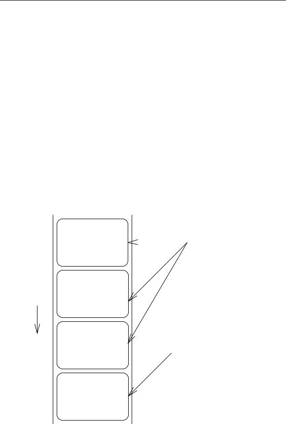
Setting edge sensor selection
Code |
[02] e |
Function |
Changes paper position detection sensor to transparent-type. |
|
Used for detecting paper gap between label papers, die-cut paper, |
|
notch hole for tag paper, etc. This setting is used as default. |
Caution |
If not detected properly, check the sensor position. |
Example |
Paper gap between label papers and notch holes for tag paper in Fig |
|
below is detected. |
Label paper gap |
Tag paper notch holes |
ABCDEF |
|
|
No 0001 |
|
ABCDEF |
|
No 0002 |
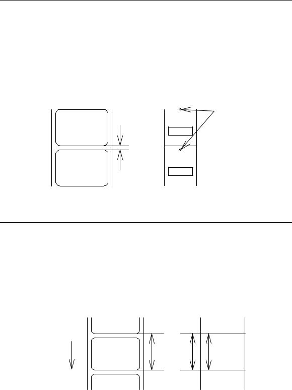
Label one sheet feed
Code |
[02] F |
Function Feeds label one sheet. The amount of feed is the length from the bottom of the label paper to the next bottom of the label paper. When using continuous paper, feeds paper the length currently set ([02] c nnnn).
Performed in the same way as operated from the Feed key on the control panel.
Label paper
Direction of feed
Amount of feed
Continuous paper
Paper length
[02] cnnnn
1-21

Setting peeling (cutting) position
Code
Units
Setting
Function
Caution
[02] f nnn
0.01 inch (0.1mm)
nnn 3-digit data
Initial value and its set range vary depending on the command setting.
|
|
|
|
Inch system |
|
|
Metric system |
|
||
|
|
|
Initial |
Minimum |
Max |
Initial |
|
Minimum |
|
Max |
|
|
|
value |
value |
value |
value |
|
value |
|
value |
|
|
|
|
|
|
|
|
|
|
|
|
|
|
|
|
|
|
|
|
|
|
|
DMI / DMW |
|
|
|
|
|
|
|
|
|
|
Normal |
|
000 |
000 |
200 |
000 |
|
000 |
|
508 |
|
|
|
|
|
|
|
|
|
|
|
|
Cutter |
|
100 |
000 |
200 |
254 |
|
000 |
|
508 |
|
|
|
|
|
|
|
|
|
|
|
|
Peel |
|
050 |
000 |
150 |
127 |
|
000 |
|
381 |
|
|
|
|
|
|
|
|
|
|
|
|
Tear Off |
|
070 |
000 |
170 |
178 |
|
000 |
|
432 |
|
|
|
|
|
|
|
|
|
|
|
|
DM4 / DM8 |
|
|
|
|
|
|
|
|
|
|
Normal |
|
220 |
220 |
420 |
559 |
|
559 |
|
1067* |
|
|
|
|
|
|
|
|
|
|
|
|
Cutter |
|
340 |
240 |
440 |
864 |
|
610 |
|
1118* |
|
|
|
|
|
|
|
|
|
|
|
|
Peel |
|
270 |
220 |
370 |
686 |
|
559 |
|
940 |
|
|
|
|
|
|
|
|
|
|
|
|
Tear Off |
|
290 |
220 |
390 |
737 |
|
559 |
|
991 |
|
|
|
|
|
|
|
|
|
|
|
|
DPP |
|
|
|
|
|
|
|
|
|
|
Normal |
|
110 |
110 |
310 |
279 |
|
279 |
|
787 |
|
|
|
|
|
|
|
|
|
|
|
|
Cutter |
|
230 |
130 |
330 |
584 |
|
330 |
|
838 |
|
|
|
|
|
|
|
|
|
|
|
|
Peel |
|
146 |
96 |
246 |
371 |
|
244 |
|
625 |
|
|
|
|
|
|
|
|
|
|
|
|
Tear Off |
|
166 |
96 |
266 |
422 |
|
244 |
|
676 |
|
|
|
|
|
|
|
|
|
|
|
|
*In setting 4-digit value, use [02] Kf command. |
|
|
|
|
|||||
With the setting above, the distance between paper sensor and cutter or peeler can be specified.
When nnn is small, the amount of feed is small, so printed label will be cut.
When nnn is appropriate, the label is fed the required amount, then cut at the paper gap.
When nnn is large, the amount of feed is large, so the next printing label will be cut.
If value out of range is specified, the command parameter will be ignored.
If optional functions such as cutter, peeler and ejection are turned on from the control panel, their initialization values will be set automatically. These initialization values, however, vary depending on the specifications of each option. For details, see the instruction manuals of each option.
Once this command was set, auto-setting function is stopped due to priority for user's specification. Do not set this command if not necessary.
1-22

Figure
Cutter Ejection Peeler Print head
Paper sensor
A |
B |
C |
Note: Peeler option is not available for CLP-8301
Printing edited or formerly-printed format
Code
Function
Caution
Example
Input data
[02] G
Prints label data for former printing or formatting.
This command is effective only when label data for former printing or formatting is left in the internal memory. If power is turned off or reset is performed, data in the internal memory will be cleared, so this command will not be effective.
Input data below represents that after ending label format printing data "ABC" one sheet, printing for the same data is executed again with this command [02] G.
[02] n |
Sets units to inch system |
[02] L |
Starts label format mode |
D22 |
Sets pixel size |
190001001000050ABC |
Sets character data "ABC" with smooth |
|
font 48pt |
E |
Ends label format mode and prints |
[02] G |
Executes 1-sheet printing for edited |
|
format |
1-23
Graphics data block input command
Code |
[02] I m a f name, data |
|
Transmission |
m |
Storing memory module specification |
data
Allocation of modules varies with command settings. Refer to the table below.
Function
Caution
Allocation of module
on-board S D-RAM
on-board flash memory
PCMCIA Card (option)
Current memory module
Command Set
DMI / DMW |
DM4 / DM8 |
DPP |
D |
A |
B |
G |
B |
A |
E or F |
E or F |
E or F |
on-board |
on-board |
on-board |
SD-RAM |
SD-RAM |
SD-RAM |
|
|
|
fGraphics data format
F 7-bit image loading file
I 8-bit image format (image saved in reverse) i 8-bit image format (image saved in normal) B 8-bit BMP format (saved in normal)
b 8-bit BMP format (saved in reverse) P 8-bit PCX format (saved in normal) p 8-bit PCX format (saved in reverse)
Note: For graphics data format, refer to input data examples.
name |
File name for graphics data (up to 16 characters ending |
|
with CR) |
data |
Graphics data for each format |
Stores specified format data in the specified memory module.
In the 8-bit BMP format and PCX format, data in colors other than black-and-white (two colors) cannot be used. Color or gray-scale data must be converted to black-and-white before use.
If the same file name as that of the current file is used for storing its data in the memory module, the contents of the current file will be replaced by the new image file. (Note: Working memory space is required for new image file.) Therefore, if overwrite is repeated, the data will not be stored due to lack of memory capacity. In this case, packing the data with command [02] z may store the data in the memory module.
1-24
7-bit image loading file format
7-bit image data uses ASCII format data. In this example, 7-bit image data with the file name of “MARK7” is stored in the memory card and printed out. Value of inside [ ] is shown in hex format.
[02]IBFMARK7 --------------- |
Graphics data input command |
8006000041040000 ---------- |
After this, 7-bit image data follows |
80060000C30C0000 |
Top data “80” is a starting code for image data |
8006000186180000 |
Next data “06” following “80” is the number of data in |
800600030C300000 |
horizontal direction |
800600071C700000 |
|
8006000618600000 |
|
8006000618600000 |
|
8006000618600000 |
|
8006000618600000 |
|
800600030C300000 |
|
800600030C300000 |
|
8006000186180000 |
|
80060001C71C0000 |
|
80060000C30C0000 |
|
80060000C30C0000 |
|
80060000C30C0000 |
|
80060030C30CC000 |
|
800600F18618F000 |
|
800603E186187C00 |
|
800607830C301E00 |
|
8006070F3CF00E00 |
|
80060E1E79E00700 |
|
80060C3861800300 |
|
80061C0000000380 |
|
80061C0000000380 |
|
80060C0000000300 |
|
80060E0000000700 |
|
8006070000000E00 |
|
8006078000001E00 |
|
800603E000007C00 |
|
800601F80001F800 |
|
800600FC0007F000 |
|
8006003F803FC000 |
|
8006000FFFFF0000 |
|
80060003FFFC0000 |
|
800600007FE00000 |
|
FFFF ------------------------------------ |
Graphics data ending code |
[02] m |
|
[02] M1500 ---------------------------- |
Sets maximum label length |
[02] L ------------------------------------ |
Starts label format |
D22 |
|
1Y1100001000500MARK7 -------- |
Develops “ MARK7” graphics data to specified position |
E ----------------------------------------- |
Starts printing |
1-25
8-bit image format
8-bit image data uses ASCII format data. In this example, 8-bit image data with the file name of “MARK8” is stored in the memory card and printed out. Value of inside [ ] is shown in hex format. (Note: Data below is described in hex.)
[01][44][0D]--------------------------- |
Stops immediate execution command |
|
|||||
|
|
|
|
(Required only for 8-bit image data) |
|||
[02][49][42][69][4D][41][52][4B][38][0D]----------- |
Graphics |
┐ |
|
||||
[00][01][00][08][00][01][00][02][00][7F][00][7F][00][E0][00][24]---------- |
|
||||||
[80][06][00][00][41][04][00][00] |
|
|
|
|
|
Data on header is fixed except |
|
|
|
|
|
|
|||
[80][06][00][00][C3][0C][00][00] |
|
|
|
|
|
||
|
|
|
|
|
for |
the last 2 bytes, i.e., “00” |
|
[80][06][00][01][86][18][00][00] |
|
|
|
|
|
||
|
|
|
|
|
“24”(36 lines in this example) |
||
[80][06][00][03][0C][30][00][00] |
|
|
|
|
|
||
|
|
|
|
|
|
|
|
[80][06][00][07][1C][70][00][00] |
|
|
|
|
|
|
|
|
|
|
|
|
|
|
|
[80][06][00][06][18][60][00][00] |
|
After this, 8-bit image data follows |
|
||||
[80][06][00][06][18][60][00][00] |
|
|
|||||
|
Top |
data “80” |
is a starting |
code |
for |
||
[80][06][00][06][18][60][00][00] |
|
image data |
|
|
|
||
[80][06][00][06][18][60][00][00] |
|
|
|
|
|||
|
Next |
data “06” |
following “80” is |
the |
|||
[80][06][00][03][0C][30][00][00] |
|
||||||
|
number of data in horizontal direction |
||||||
[80][06][00][03][0C][30][00][00] |
|
||||||
|
|
|
|
|
|
|
|
[80][06][00][01][86][18][00][00] |
|
|
|
|
|
|
|
[80][06][00][01][C7][1C][00][00] |
|
|
|
|
|
|
|
[80][06][00][00][C3][0C][00][00] |
|
|
|
|
|
|
|
[80][06][00][00][C3][0C][00][00] |
|
|
|
|
|
|
|
[80][06][00][00][C3][0C][00][00] |
|
|
|
|
|
|
|
[80][06][00][30][C3][0C][C0][00] |
|
|
|
|
|
|
|
[80][06][00][F1][86][18][F0][00] |
|
|
|
|
|
|
|
[80][06][03][E1][86][18][7C][00] |
|
|
|
|
|
|
|
[80][06][07][83][0C][30][1E][00] |
|
|
|
|
|
|
|
[80][06][07][0F][3C][F0][0E][00] |
|
|
|
|
|
|
|
[80][06][0E][1E][79][E0][07][00] |
|
|
|
|
|
|
|
[80][06][0C][38][61][80][03][00] |
|
|
|
|
|
|
|
[80][06][1C][00][00][00][03][80] |
|
|
|
|
|
|
|
[80][06][1C][00][00][00][03][80] |
|
|
|
|
|
|
|
[80][06][0C][00][00][00][03][00] |
|
|
|
|
|
|
|
[80][06][0E][00][00][00][07][00] |
|
|
|
|
|
|
|
[80][06][07][00][00][00][0E][00] |
|
|
|
|
|
|
|
[80][06][07][80][00][00][1E][00] |
|
|
|
|
|
|
|
[80][06][03][E0][00][00][7C][00] |
|
|
|
|
|
|
|
[80][06][01][F8][00][01][F8][00] |
|
|
|
|
|
|
|
[80][06][00][FC][00][07][F0][00] |
|
|
|
|
|
|
|
[80][06][00][3F][80][3F][C0][00] |
|
|
|
|
|
|
|
[80][06][00][0F][FF][FF][00][00] |
|
|
|
|
|
|
|
[80][06][00][03][FF][FC][00][00] |
|
|
|
|
|
|
|
[80][06][00][00][7F][E0][00][00] |
|
|
|
|
|
|
|
[46][46][46][46] ------------------------- |
Graphics data ending code |
|
|
||||
[02] m [0D] |
|
|
|
|
|
|
|
[02] M1500 [0D]------------------------- |
Sets maximum label length |
|
|
||||
[02] L [0D] ------------------------------- |
Starts label format |
|
|
||||
1Y1100001000500MARK8[0D] ----- |
Develops “ MARK8” graphics data to specified position |
||||||
E [0D] ------------------------------------- |
Starts printing |
|
|
|
|||
1-26

Download of TrueType Font
Code
Transmission data
[02] i m T nn name <CR> xxxxxxxx data…
m Storing memory module specification
Allocation of modules varies with command settings. Refer to the table below.
Allocation of module
on-board S D-RAM
on-board flash memory
PCMCIA Card (option)
Current memory module
Command Set
DMI / DMW |
DM4 / DM8 |
DPP |
|
|
|
D |
A |
B |
|
|
|
G |
B |
A |
|
|
|
E or F |
E or F |
E or F |
|
|
|
on-board |
on-board |
on-board |
SD-RAM |
SD-RAM |
SD-RAM |
T T fixed (TrueType)
Function
Caution
Example
Input data
nn Two-digit font ID
Valid values: 50 – 59, 5A – 5Z, 5a – 5z,
60 – 69, 6A – 6Z, 6a – 6z,
:
90 –99, 9A – 9Z, 9a – 9z
name Font name (Max. 16 characters followed by CR code to end)
xxxxxxxx TrueType font data size, number of bytes assigned by 8 digits hexadecimal characters.
data |
TrueType font data |
Stores specified font data in the specified memory module.
File will be overwritten when the font data is stored in the memory module using the same name of the existing file. Therefore, free space for the file to write new data will be necessary.
The following command line shows the command to download 34754 bytes of TrueType font file, named “Tree Frog”, with the font ID 52 into the memory module B:
[02] iCT52TreeFrog<CR>000087C2 data…
1-27

Pause per label printing
Code |
[02] J |
Function Performs pause each time label is printed one sheet. Used when label peeling detection sensor is not mounted on the printer incorporating peeling function. Pause is cancelled by pressing Pause key on the control panel.
Caution |
To clear this function, reset the printer. |
1-28
 Loading...