

Page 1

User guide T2150 T2250 Matrix printer
Page 2

Page 3

User guide Table of contents
Table of contents
Introduction 1
Printer features 1
Symbols used 1
Printer at a glance 2
Printer in tractor mode 3
Printer in single-sheet mode 3
Paperway 4
Installation 5
Unpacking the printer 5
Placing your printer 6
Checking the printer voltage 7
Connecting the printer 8
Switching on the printer 9
The control panel 10
The LC display 11
Online mode 12
Offline mode 12
Setup mode 13
Messages in the LC display 14
Key functions when turning on the printer 15
Changing the ribbon cassette 16
Printer drivers 19
Installing a printer driver in Windows 95/98/ME 19
Installing a printer driver in Windows 2000/2003/XP 19
Installing a printer driver in Windows 7 21
Installing a printer driver in Windows Vista 22
Other operating systems 23
Changing printer settings 24
Form settings (Windows 2000/2003/XP/Vista/Windows 7) 24
Loading optional firmware 25
Troubleshooting 25
I
Page 4

Table of contents User guide
Paper handling 27
Changing the paper type 27
Changing the paper type in the setup menu 28
Selecting character density and font 29
Loading paper 30
Fanfold paper 30
Single sheets 34
Paper transport 36
Moving the paper to the tear position 37
Removing paper 37
Settings 38
Setting the print head gap 38
Setting the tear position 39
Setting the first printing line (TOF) 40
The Menu 41
Programming via the control panel 41
Enabling access to menu mode 41
Calling up the menu 41
Menu configurations 42
Menu handling 43
Save settings 43
Selecting the LC display language 44
Terminating Setup mode 45
Menu structure 46
Menu parameters 47
Printing out menu configurations (Print) 47
Loading menu configurations (Menu) 47
Reset to default values (Reset) 48
Quietmode (Quietm.) 48
48
Selecting font (Font) 49
Setting character density (CPI) 50
Setting line spacing (LPI) 50
Skiping perforation (Skip) 51
Selecting start signal for escape sequence (ESCChar) 51
Selecting emulation (Emulate) 52
II
Page 5

User guide Table of contents
Bidirectional printing (Bidir) 52
Settings for interfaces (I/O) 53
Serial interface (Serial) 53
Data transmssion rate (Baud) 53
Data format (Format) 54
Further Settings (Special) 55
Error handling (ErrMode) 55
Block end character (Blockend) 55
Signal feedback (Remote) 56
Transparence (Handthr) 56
Protocol (Protocol) 57
Signal Processing (DTR) 57
Selecting interface (Interf.) 58
Interface buffer (Buffer) 58
Ethernet interface
(ETH-EXT) option 59
Selecting character set
(CG-Tab) 59
IBM character set (CharSet) 59
National character set (Country) 60
Slashed zero
(Sl.Zero) 60
Automatic carriage return (Auto-CR) 61
Automatic line feed
(Auto-LF) 61
Menu lock (MenLock) 62
Language (Language) 62
Paper parameters (Paper) 63
Form length (Forml) 63
First printing position (FormAdj) 65
Printhead gap manually (Head) 66
View and tear position (AutoTear) 67
Line length (Width) 68
Barcode (Barcode) 68
Normal characters and barcode (Barmode) 69
Form feed mode (FFmode) 70
Setting and activating options (PapOpt) 71
Activation of tractors (AutoTra) 71
Activation of automatic sheet feeder (AutoASF) 72
Setting the left margin (LeftMrg) 72
Setting the right margin (RightMrg) 73
III
Page 6

Table of contents User guide
Local copy (screen print) from a Coax or Coax/IPDS
(FFaftLC) 73
Enable/Disable Paper Handling Features (Paphand) 74
Menu settings (example) 75
Advanced menu 77
Test functions 77
Printer self-test (Rolling ASCII) 78
Exiting Rolling ASCII test mode 79
Interface test
(Hex-Dump) 80
Printout in Hex-Dump 80
Terminating Hex-Dump 81
Advanced settings 82
Form length (Forml) 84
Automatic gap adjustment (AGA) 85
Paper handling (Paphand) 85
Increasing the printhead gap (Head up) 86
Paper width (Pagewid) 86
Left-hand area (Leftzon) 87
Right-hand area (Rightzo) 87
Physical left margin (Physlm) 88
Bidirectional parallel interface (CX-bid) 88
Line wrap (Wrap) 89
Beep at paper end (Sound) 89
Deactivate single sheet feeder (Single) 90
Settings for paper with dark back (Pap.back) 90
Setting for printing copy paper (HvyForm) 91
Power save mode (Sleepmod) 91
Serial number (SerialN) 92
Asset number (AssetN) 92
Graphic Print Speed (GrSpeed) 93
Improvement of graphic and barcode print quality (GrFreq) 93
Activate PJL langugage (Jobcntl) 94
Increased print speed for 17.1 and 20 cpi (HS-Draft) 94
IV
Troubleshooting 95
General print problems 96
The display remains dark 96
The display is lit, but the printer does not print 96
Problems with the paper feed 97
Page 7

User guide Table of contents
Paper jam (fanfold paper) 97
Paper jam (single sheets) 98
Paper does not move to tear off position 98
Problems with the print quality 99
Print is too pale 99
Smudged print 99
Prints undefined characters 99
The first line is not completely printed out at the top 99
Dots within characters are missing 99
Error messages via the display 100
Additional display messages 103
Care and maintenance 105
Replacing the fuse 105
Cleaning the housing 106
Cleaning the interior 106
Cleaning the platen 107
Ribbon 107
Cleaning the upper friction 108
Carriage shafts 108
Specifications 109
Printer specifications 109
Interface specifications 113
Paper specifications 114
Character sets 117
MTPL standard character set 118
MTPL, international substitution characters 119
OCR-A character set 120
OCR-B character set 121
Available character sets and fonts 122
Emulations 125
General 125
Escape sequences 125
What are escape sequences? 126
MTPL sequences 126
V
Page 8

Table of contents User guide
Control codes 126
The $$ procedure 126
Example: 126
How are escape sequences used? 127
MTPL 127
Example in BASIC 127
Example in Pascal 127
Printout 127
List of available control codes 128
PJL commands 138
Barcode 139
List of available barcodes 139
US Postnet barcode 140
Royal Mail Customer barcode 140
KIX barcode 141
USPS Intelligent Mail barcode 141
LC printing 142
List of additional control codes 143
Interfaces 145
Parallel interface 146
Connector assignment 146
Serial interface V.24/RS232C 147
Connector assignment 147
Interface cable (serial interface) 148
Input signals 148
Output signals 148
Protocols 149
Memory mode XON/XOFF 149
Memory mode Robust XON/XOFF 149
Extended menu functions with the ENQ/STX and
ETX/ACK protocols selected 149
ENQ/STX protocol 150
ETX/ACK protocol 150
Options and accessories 151
Options 151
Automatic cut sheet feeder, front (ASF-F) 151
Automatic cut sheet feeder, rear (ASF-R) 151
Tractor 2, front 151
VI
Page 9

User guide Table of contents
Tractor 3, rear 151
Serial interface adapter 151
Optional paper support 151
Pocket Ethernet interface 151
Serial interface RS232/TTY 151
Others 151
Accessories 152
Ribbon cassettes 152
Programmer’s application manuals 152
Index 153
VII
Page 10

Page 11

User guide Introduction
Introduction
Printer features Your printer has outstanding product features, e.g. high printing speed
and print quality plus flexible paper management, making it a highly
professional solution for many industrial sectors – particularly those
which use continuous paper and generate large volumes of print on a
daily basis.
Symbols used Important information is highlighted in this manual by two symbols.
CAUTION highlights information which must be observed in order to
STOP
prevent injuries to the user and damage to the printer.
NOTE highlights general or additional information about a specific
topic.
1
Page 12
Printer at a glance User guide
1
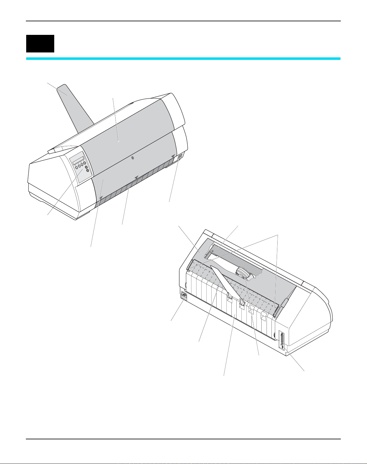
Paper support
Control panel
Printer at a glance
Front cover
nepootl
lup
Bottom cover
nepootllup
Power switch
Top cover
Ribbon cassette
Latches
Single sheet feeder closed
Power inlet and
fuse
Tear edge
Rear cover
Print head
Interface connector
2
Page 13
User guide Printer at a glance
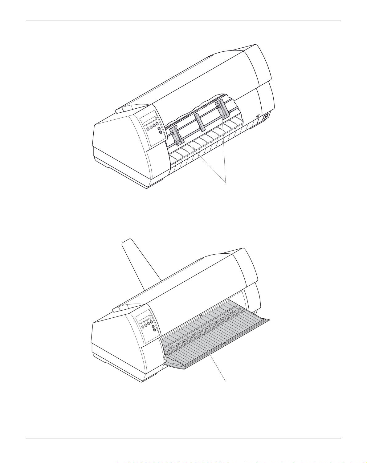
Printer in tractor mode
nepo
o
tllu
p
Tractor 1
Printer in single-sheet mode
Single sheet feeder open
3
Page 14
Printer at a glance User guide
T
r
a
c
t
o
r
3
T
r
a
c
t
o
r
1
T
ra
c
to
r 2
Single sheet
A
S
F
-
F
A
S
F
-
R
Paperway
` Fanfold paper mode
Standard printer: Tractor 1
Single sheet
Options: Tractor 2
Tractor 3
F
-
F
S
A
A
S
F
-
R
T
r
3
r
o
t
c
a
r
T
a
c
t
o
r
1
Single sheet
T
ra
c
to
r 2
If you install the ASF-Ffeeder, the
paper sources Trac2 and Single are
omitted.
ASF-F
ASF-R
Tractor 2 and tractor 3: option, modular
4
Page 15
User guide Installation
2
Installation
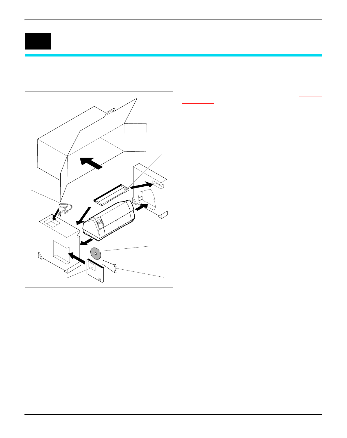
Unpacking the printer
➂
➃
Place your printer on a solid surface (see Placing
your printer, page 6).
Make sure that the “Up” symbols point in the correct direction.
Open the packaging, take out the accessory cassette and unpack it. Pull the printer out of the cardboard box towards you and remove the remaining
packaging material.
Check the printer for any visible transport damage
and completeness. Apart from this CD-ROM (
the Quick start guide (
the ribbon (
included.
If you find any transport damage or if any accessories are missing, please contact your dealer.
f) and the paper support (g) must be
d), the power cable (e),
c)
➁
➀
➄
5
Page 16
Installation User guide
C
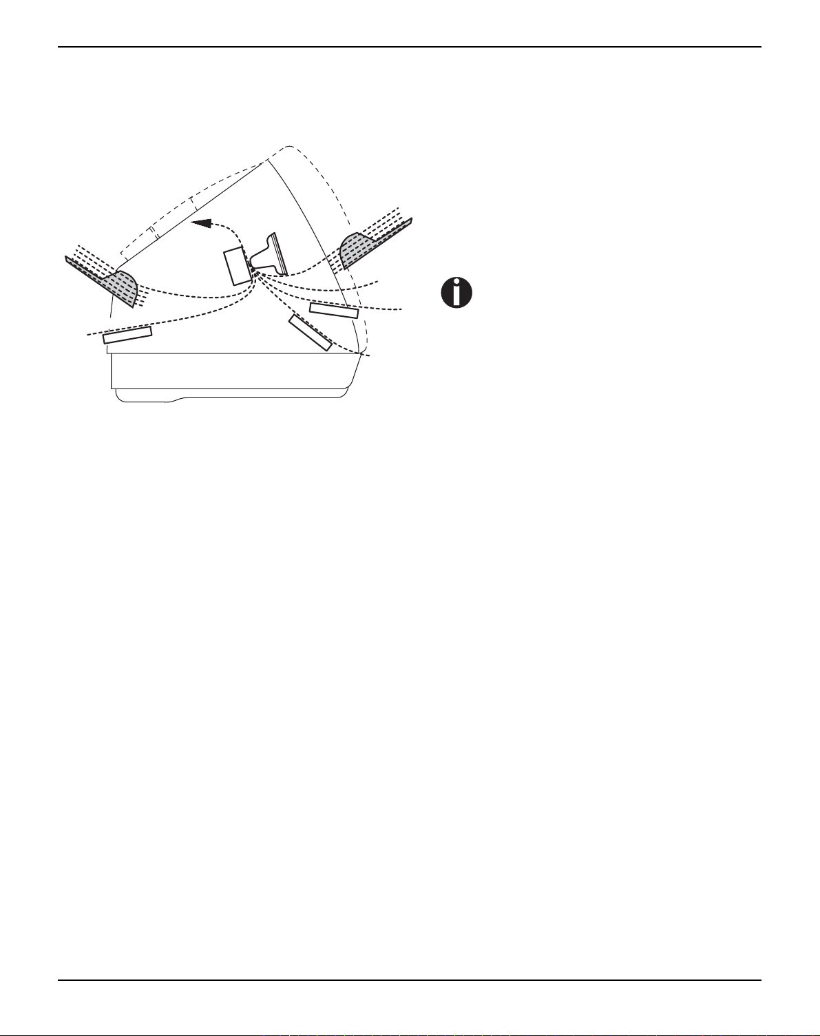
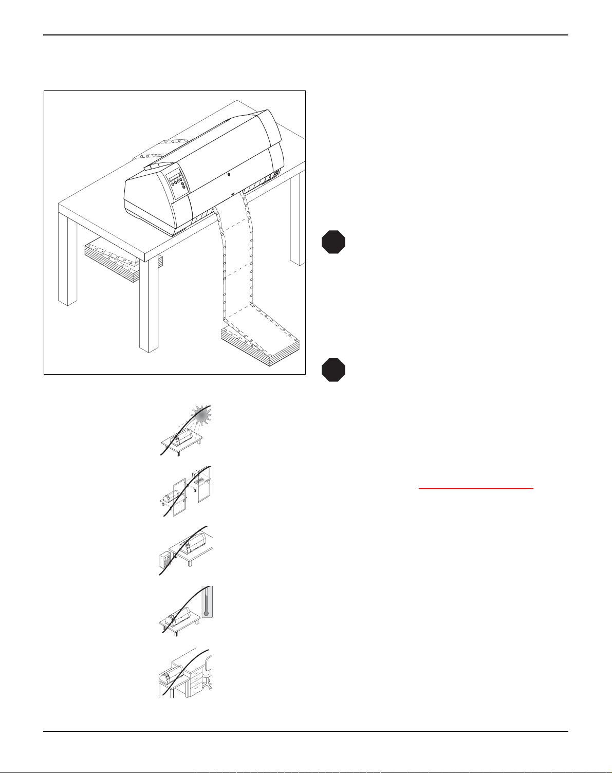
Placing your printer
Place the printer on a solid, flat, surface, ensuring
that the printer is positioned in such a way that it
can not topple, and that there is easy access to the
control panel and paper input devices. Also ensure that there is sufficient space for the printed output.
If you expect that frequent forward and reverse
feeds will occur, you should place the printer as
shown in the figure, if possible.
STOP
The power supply cable may be damaged if the paper edges constantly chafe
the insulating sheath. The user must
always ensure that there is sufficient
distance between the power supply
cable and the paper.
When selecting the printer location, observe the
following additional instructions:
STOP
Never place the printer in the vicinity of
inflammable gas or explosive substances.
Do not expose the printer to direct sunlight. If you cannot avoid placing the printer near a window, protect it from the sunlight with a curtain.
When connecting the computer with the printer, make sure not to exceed the permitted cable length (see Interface specifications
,
page 113).
Ensure sufficient distance between the printer and any heating radiators.
2
1
0
90
80
Avoid exposing the printer to extreme temperature or air humidity
70
60
50
40
30
20
10
fluctuations. Above all take care to avoid the influence of dust.
0
-10
It is recommended to install the printer in a place which is acoustically isolated from the workplace because of the noise it may
produce.
6
Page 17
User guide Installation
V
V
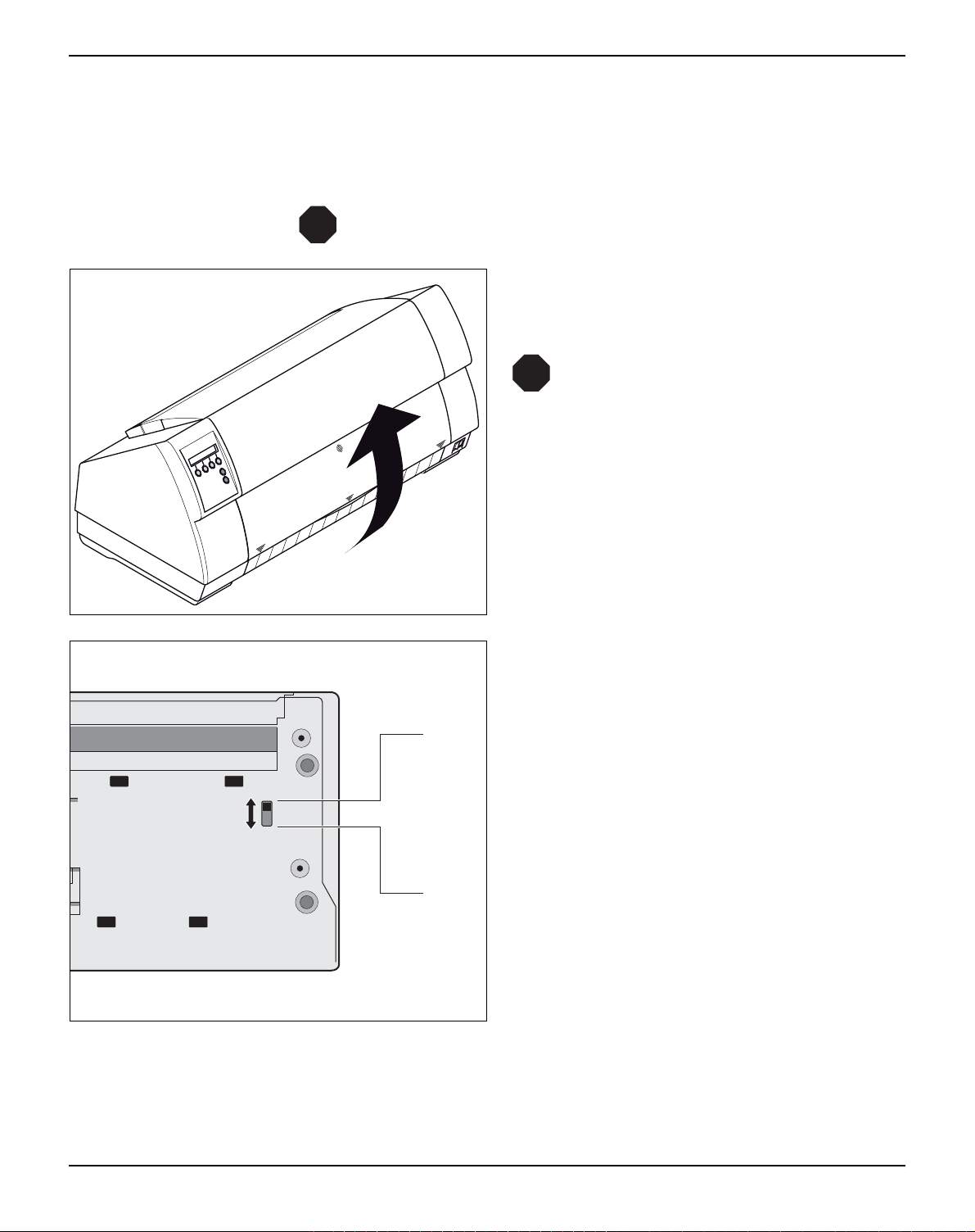
Checking the printer voltage
ne
poo
t
llup
STOP
Make sure that the device has been set to the correct voltage (e.g.
230 V in Europe, 120 V in the USA). To do this, check the type plate
above the power inlet at the back of the printer. Contact your dealer
if the setting is incorrect.
Never switch on the printer if the voltage setting is incorrect,
since this may result in severe damage.
You can set the printer to the correct mains voltage yourself. To do this, cautiously tilt the printer to
the rear.
STOP
nepootllup
Make sure that the fixing clips of the
parallel connection are not bent.
Front side of the printer
Rear side of the printer
Use a suitable object (e.g. a screwdriver, but
never a pencil) to set the slide switch on the left at
the bottom of the printer to the correct voltage.
120
230
7
Page 18
Installation User guide
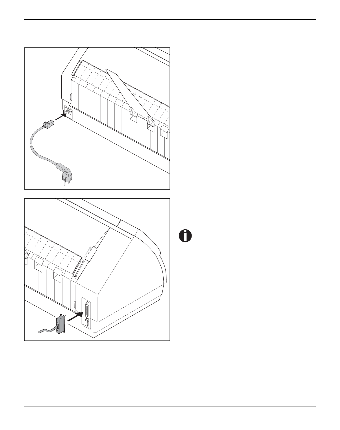
Connecting the printer
Connect the power cable to the power inlet of the
printer. Connect the power cable plug to a mains
socket.
Make sure that the printer and the computer are
switched off and connect the data cable between
the printer and the computer.
The printer by default is provided with a
parallel interface. For further information about the interfaces, refer to the
section Interfaces
, page 145.
8
Page 19
User guide Installation
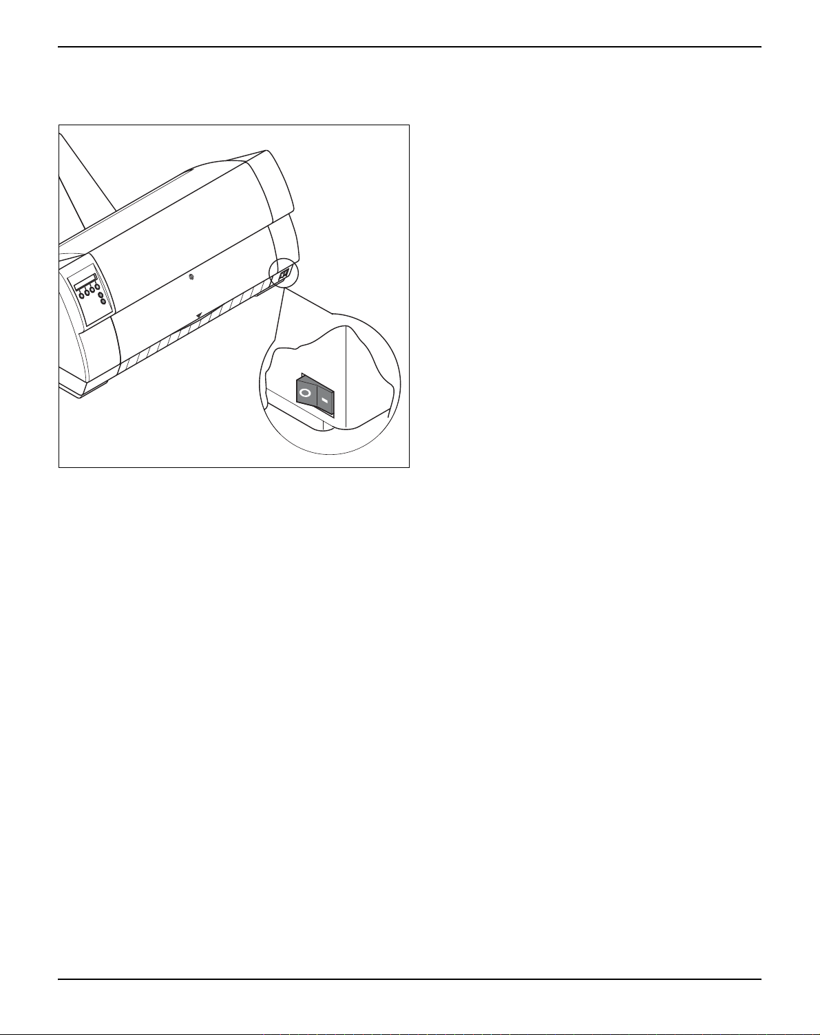
Switching on the printer
The power switch for switching on the printer is located at the bottom right at the front of the printer
when viewed from the front.
9
Page 20

The control panel User guide
3
The control panel
The control panel keys are used for controlling your work with the
printer. The control panel is located on the front right side of your
printer and consists of a two-line LC display and six keys.
The functions of the keys depend on the printer’s current mode (status). There are four basic modes.
` The Online mode is the printer’s normal operating mode. Data from
your computer can be received and printed.
` In the Offline mode the link between printer and computer is inter-
rupted, i.e. no data can be received and printed.
` In the Setup mode you can either select the printer menu or carry
out the so-called quick-switch function. The quick-switch option was
included so that you can change the most important parameters (for
example adjustments, character density, font, paper path, adjustments i.e. head gap) directly without having to enter them via the
menu. The settings for the parameters character density and font
are lost when the printer is switched off. They can be selected permanently in the menu mode of the printer.
` In the Menu mode further printer settings (line spacing, size of the
interface buffer etc.) can be altered and saved permanently.
10
Page 21
User guide The control panel
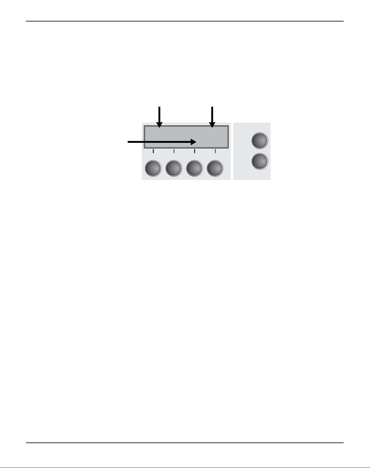
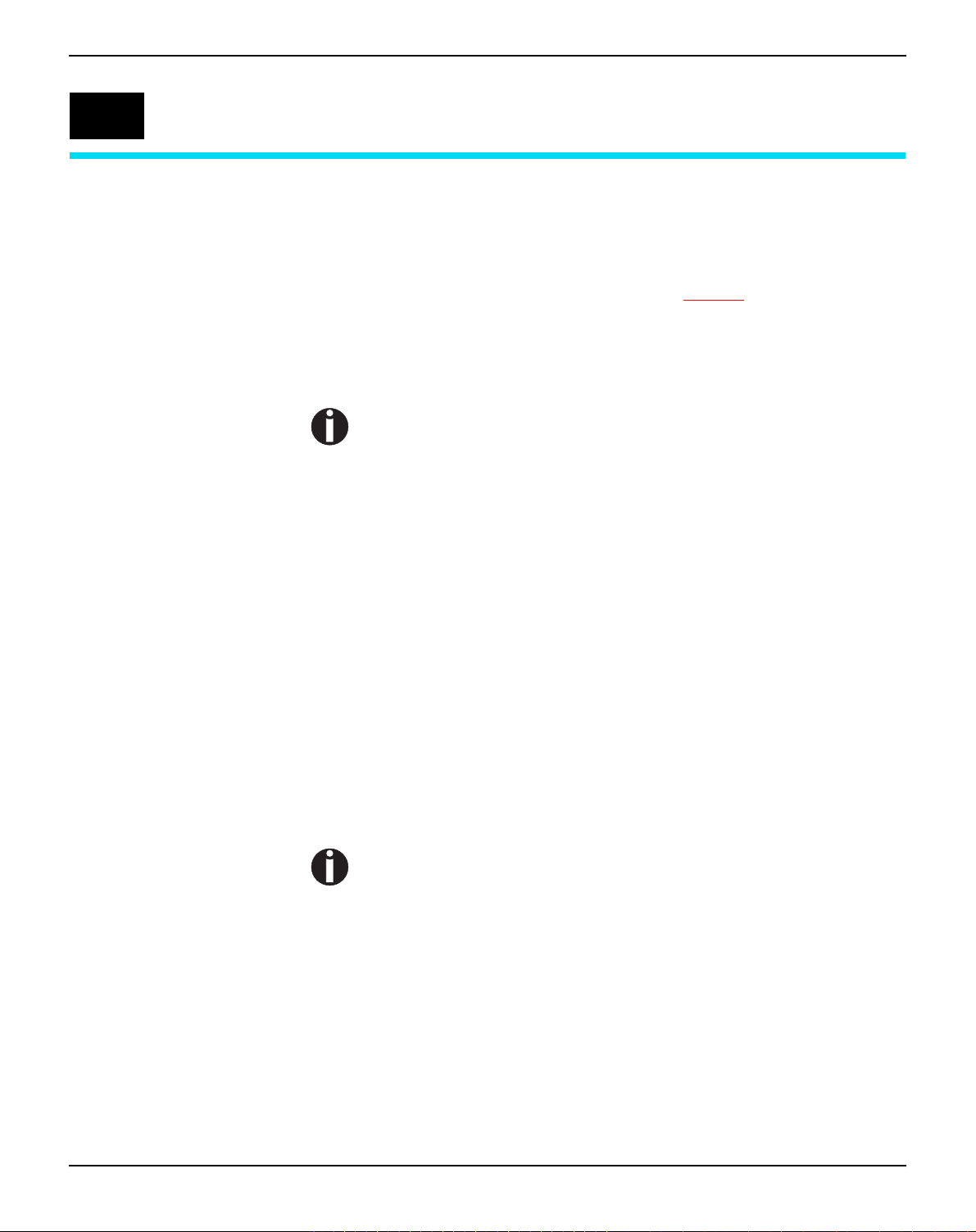
The LC display The LC display tells you all the important printer settings and informs
you which functions are currently assigned to which keys.
The upper line informs you that the printer is either in online or offline
mode (in the example below the printer is in the Online mode), and
the selected paperpath (below: Tractor1 = tractor mode).
Example:
Key functions
Printer status
Online Tractor1
Paper path
Tear
21
3
4
Online
Setup
11
Page 22
The control panel User guide
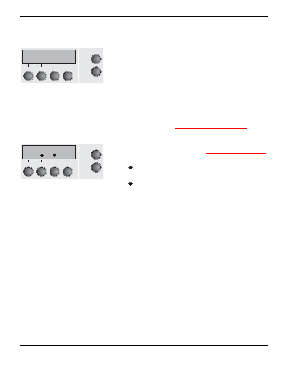
Online mode After switching on, the printer is automatically set to online mode.
Only in this mode can it receive data from the computer.
Online Tractor1
Tear
3
21
4
Online
Setup
loaded, see (see
If Load is displayed above this key, no paper is loaded in the prin-
ter or the printer is in park position. In this case the display switches between Online and Park Position. Press the key to feed
Moving the paper to the tear position, page 37).
paper to the printing position.
` Setup key: Sets the printer to setup mode.
` Online key: Sets the printer to offline mode.
Offline mode Only in this mode is it possible to perform step, line, or form feeds
` Tear key (4): Activates the tear function when fanfold paper is
Paper transport, page 36); howe-
Changing the paper
Offline Tractor1
Park Load
21
Load
3
4
Online
Setup
from the control panel, see (see
ver, data cannot be received.
` Park key (1): Clears the paper path with paper loaded and acti-
vates paper path quick selection, see (see
type, page 27).
` Key (2): Short keypress: Microstep forward. Long keypress:
Continuous paper feed.
` Key (3): Short keypress: Microstep reverse. Long keypress:
Continuous paper reverse feed up to the park position.
` Load key (4): If no paper is loaded, see above.
If paper is loaded: Loads paper from the selected paper source;
the display changes to LF/FF
Short keypress: Line Feed (LF).
Long keypress: Form Feed (FF).
` Setup key: Sets the printer to setup mode.
` Online key: Sets the printer to online mode.
12
Page 23
User guide The control panel
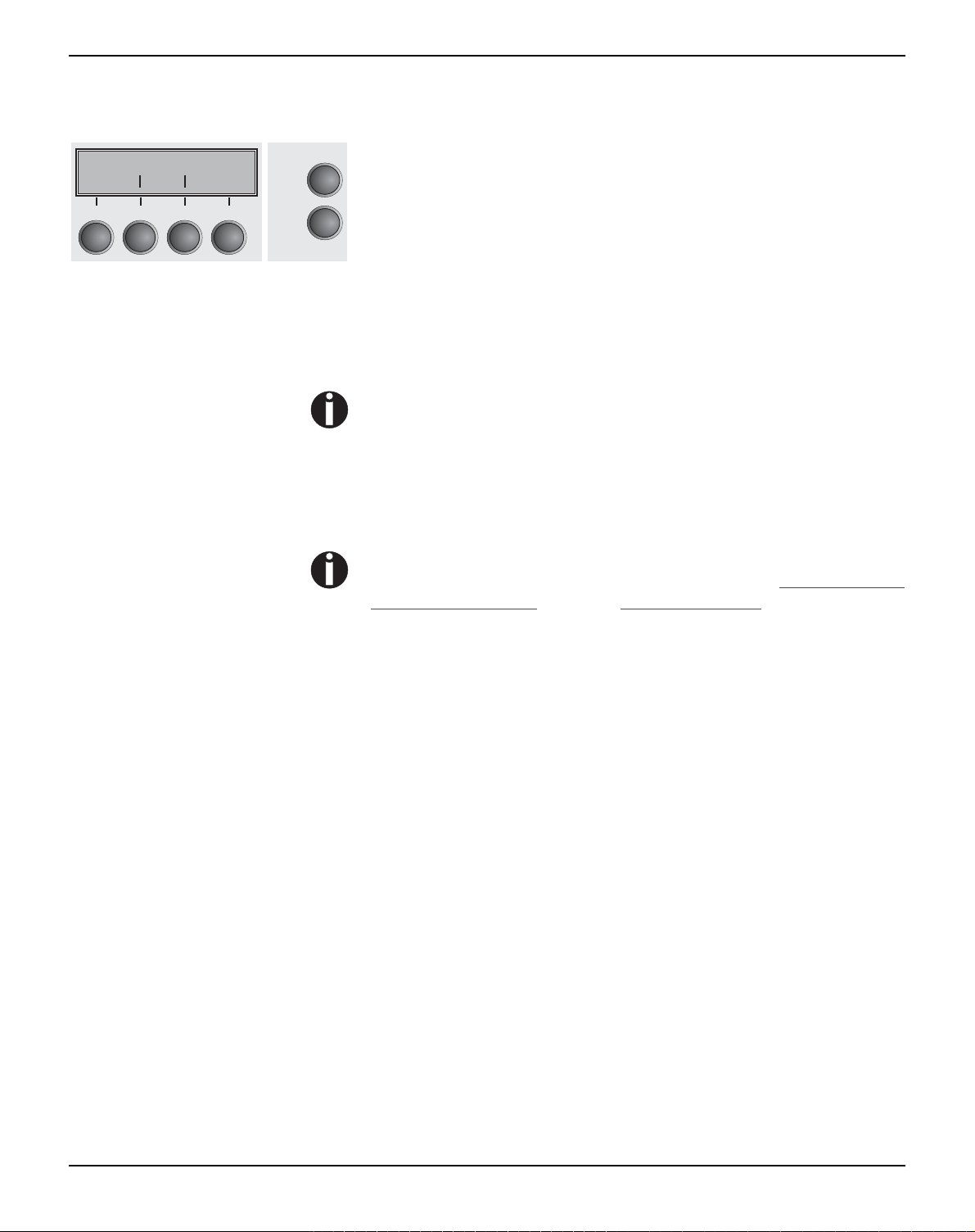
Setup mode In this mode, the following settings are available:
Adjust Paperway
Menu Char
3
21
4
Online
Setup
` Setup key: Sets the printer to setup mode, in which the following
settings can be selected:
` Menu key (1): Other menu settings. Acces may be disabled by
the manufacturer (see note below).
` Adjust key (2): Sets the Tear position, first printing line and print
head gap.
` Paperway key (3): Sets the Paper path.
` Char key (4): Sets the font and the number of characters per
inch.
Access to the other menu settings (Menu) may be disabled by
the manufacturer.
Proceed as follows to release this lock temporarily.
1 Switch off the printer for approx. 5 seconds.
2 Switch the printer on again keeping the Setup key pressed.
For information on how to enable access permanently and
about the available settings, refer to the section (see
Menu lock
(MenLock), page 62) and (see Menu parameters, page 47).
13
Page 24
The control panel User guide
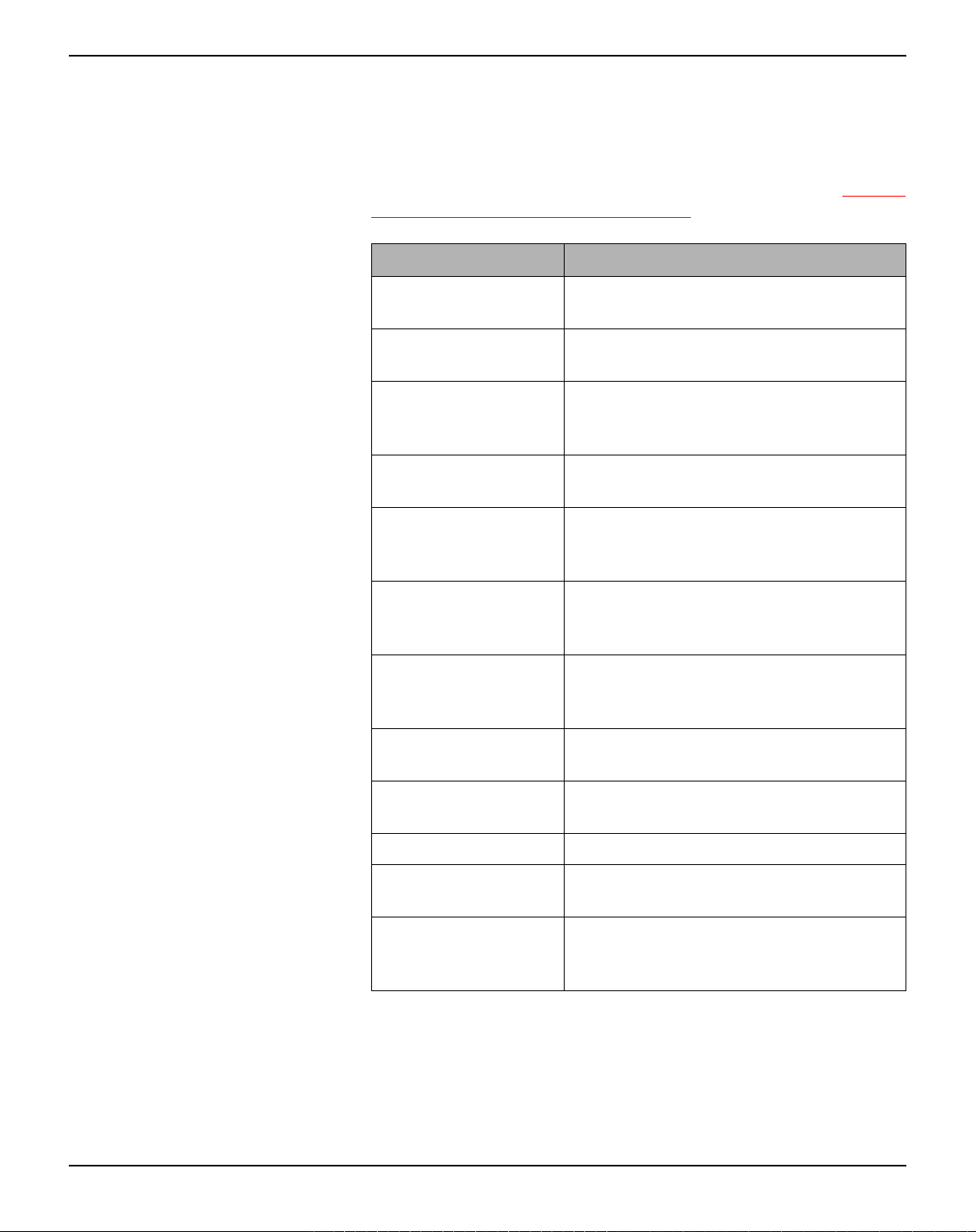
Messages in the LC display
If the printer detects an internal fault or user error or if it expects you
to do something, a message will appear in the LC display. It also displays the status during an operation (e.g. Initializing). Below you
will find a list of messages with brief descriptions of each message.
The messages are described in greater detail in the chapter (see
ror messages via the display, page 100).
Message Meaning
Eject error The printer cannot eject the paper/
advance it to park position.
Hardware Alarm Internal hardware error, contact your dea-
ler or service technician.
Initializing This message appears during the prin-
ter’s initializing phase after switching on
the printer.
Load error The printer cannot draw in the loaded
paper.
Load paper from The printer has detected paper end
during operation/printer was switched on
with no paper loaded.
Er-
Loading default Factory defined parameters will be
reloaded in all available menues after
switching on the printer.
Out of paper The printer has detected paper end
during operation / printer was switched on
with no paper loaded.
Parity error A parity error during data transmission is
indicated.
Park position Printer was switched on with no paper
loaded.
Press any key The user is requested to press any key.
Selftest After power-on, the printer executes a
short hardware self-test.
Tear Paper off The user is requested to tear off paper
which has been advanced to the tear
edge.
14
Page 25
User guide The control panel
Key functions when turning on the printer
If you keep one of the following keys pressed during power-on until
the printer has completed initialisation, the corresponding function is
activated:
` If you keep the Online key depressed while turning on the printer,
you enter the printer’s advanced menu mode. The advanced menu
mode is described in the section (see
this manual.
` If you keep the Setup key depressed while turning on the printer,
you regain access to the printer menu if you had locked it before with
the help of the MenLock function. The MenLock function is described in the section (see
` If the four function and select keys (keys 1 to 4) are depressed si-
multaneously while turning on the power, all printer settings are reset to the default values, except the Forml (Form length) and Single
setting in advanced menu mode.
This causes all the user’s previous settings to be lost.
Menu lock (MenLock), page 62).
Advanced menu, page 77) of
15
Page 26
Changing the ribbon cassette User guide
4
Changing the ribbon cassette
The ribbon consists of a dense synthetic fabric saturated with ink.
When printing, the needles hit the ribbon and transfer the ink particles on to the paper. After printing several million characters, the ink
is consumed and the fabric worn out.
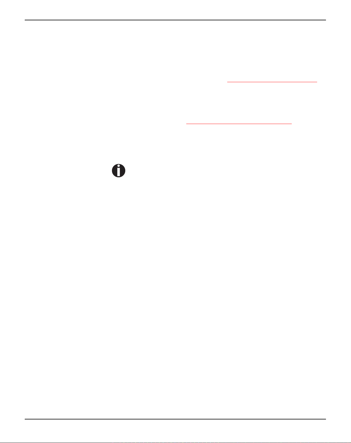
Remove all the paper from the printer and make
sure that the printer is switched off before opening
the cover.
Press the two slide latches, raise the top cover to
an angle of 90 degrees relative to the top cover of
the printer and remove it.
Cautiously slide the print head carriage to the left
stop (viewed from the printer front).
STOP
The print head becomes hot during
printing. You should therefore let it
cool down for some time before touching it.
16
Page 27
User guide Changing the ribbon cassette
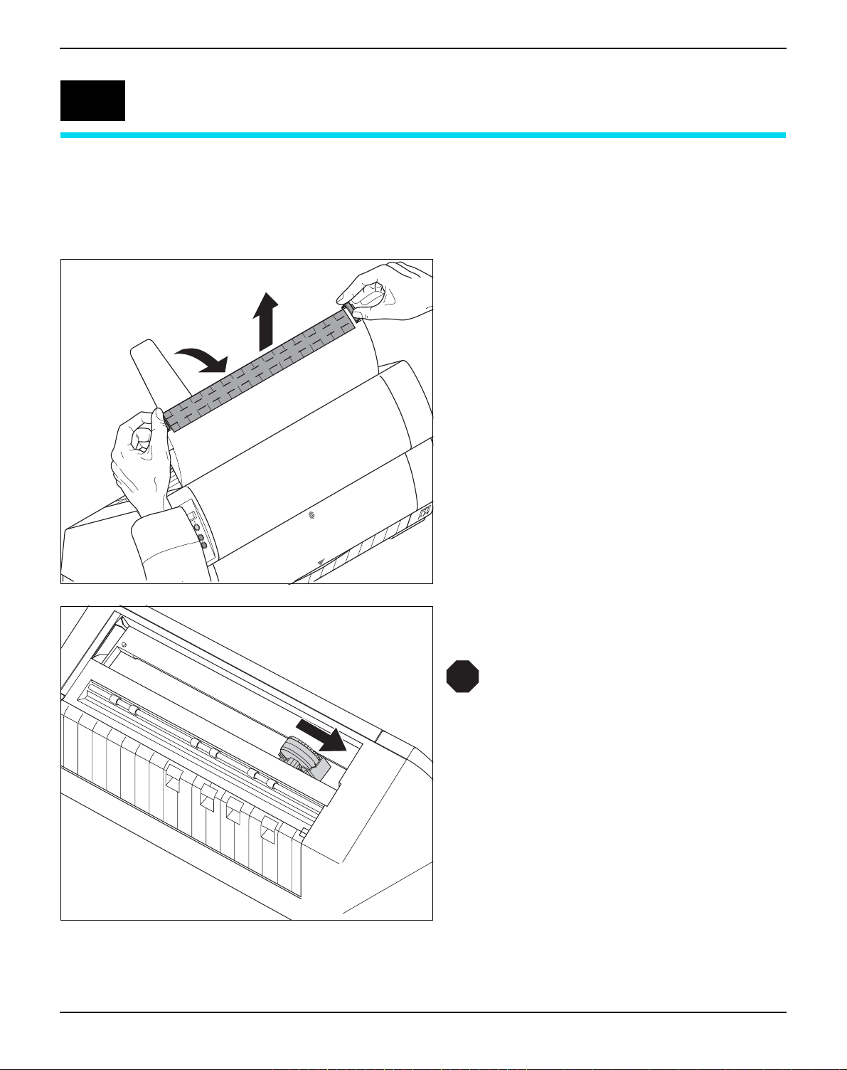
Raise the printer bar cover.
Remove the used cassette.
We recommend use of genuine ribbon
cassettes only.
Turn the coloured ribbon feed knob at the right of
the new ribbon cassette in the direction of the arrow in order to take up slack of the ribbon.
17
Page 28
Changing the ribbon cassette User guide
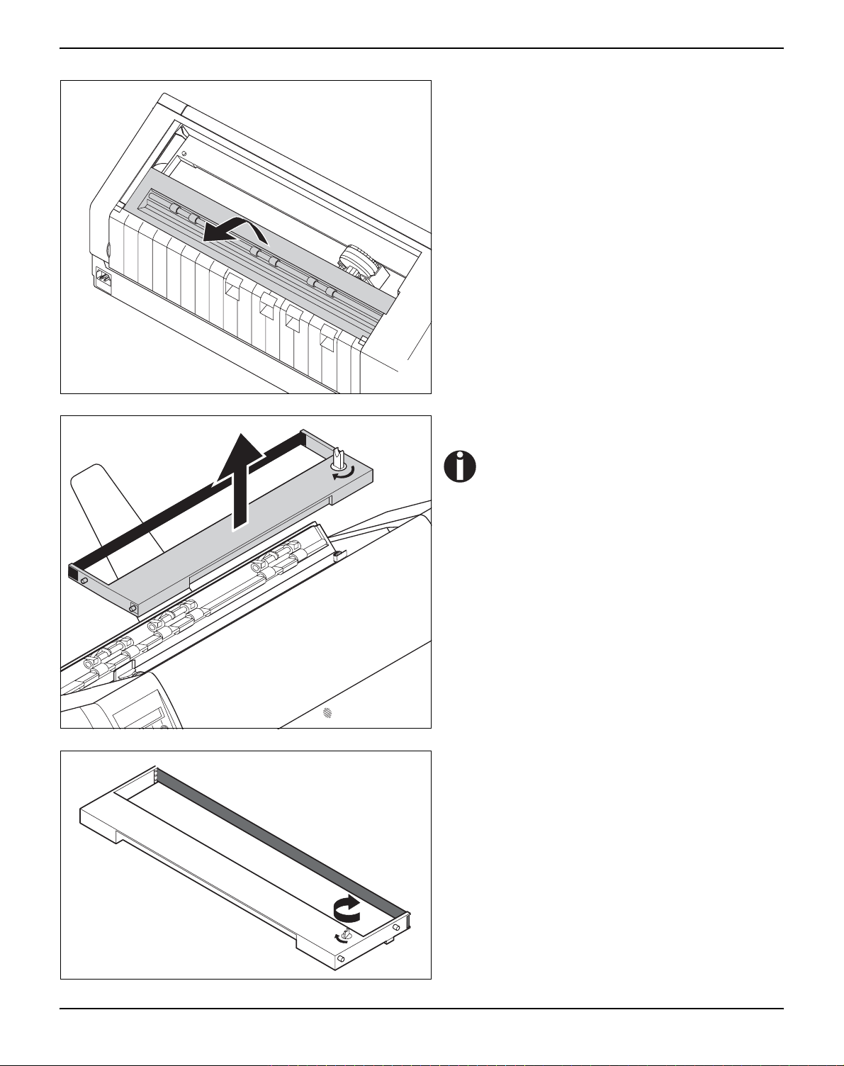
Slightly tilt the ribbon cassette forwards in such a
way that it is parallel to the housing top and thread
in the ribbon in front of the print head. Locate the
two projections in the left and right guide rails of
the printer and gently press down on both sides
until it clicks into place. In this way, the cartridge is
automatically positioned correctly.
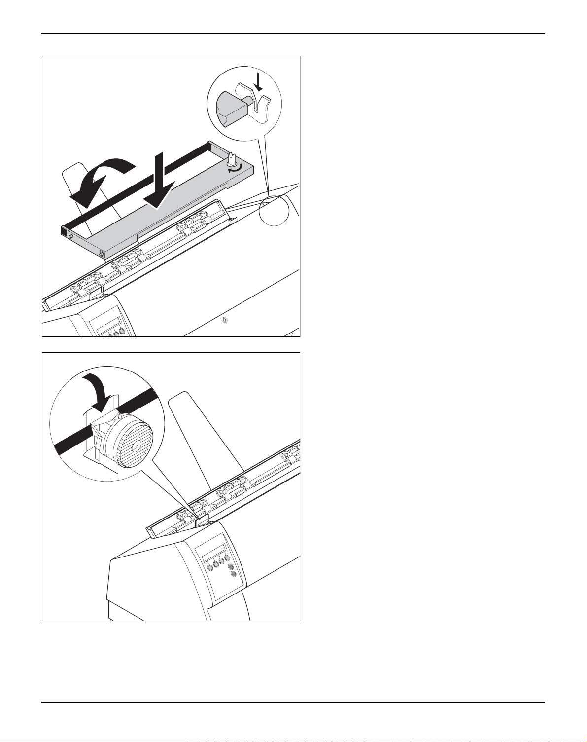
Use the knob on the right side of the cassette to
take up slack of the ribbon again. Thereby the ribbon will slide over the plastic noses on the left and
right of the print head into the correct positon.
Press the printer bar cover down until it clicks into
place, remount the top cover, making sure that the
projections on the cover are inserted correctly into
the recesses of the printer housing, and close it.
18
Page 29
User guide Printer drivers
5
Printer drivers
You need to install a printer driver so that the printer can process the
data from your application programs.
An original driver offers the best conditions for optimal printing results. All available printer drivers can be found on the CD-ROM enclosed with the printer, as well as on our Internet
can also download updated versions as necessary.
Installing a printer driver in Windows 95/98/ME
In this operating system the compatible 2150 and 2250 driver
can be used.
Installing a printer driver in Windows 2000/2003/XP
The online CD-ROM contains printer drivers for the most common
Windows applications. To install the printer driver, proceed as follows.
site, from which you
1 Insert the supplied online CD-ROM in the CD-ROM drive.
2 Click on the Start button in the Windows taskbar.
3 Click on Printers and Faxes to open the printer folder.
4 Click on File and Add Printer in the menu bar.
5 Click on Next In the Printer Installation Wizard.
6 Specify whether you want to operate the printer as a Local Printer
or Network Printer by clicking on the relevant option, then press
Next.
For instructions on installing the printer as a network printer,
please consult the documentation supplied with your network
operating system and/or printer server, or contact the network
administrator.
To install a network printer, you will need Administrator rights.
If you are using the printer locally, you can continue installing the
driver in one of two possible ways:
` Manual installation of printer driver: in this case, continue with
Step 7.
` Automatic installation of printer driver via Plug & Play function: in this
case, continue with Step 12 once the printer installation wizard has
determined the printer, port and printer name.
19
Page 30

Printer drivers User guide
Then click on Next.
7 Select the port to which your printer is connected, then click on Next.
8 Click on Data Carrier, then click on Browse.
9 Select the CD-ROM drive and open the directory n:\driver (“n“
stands for the letter of your PC drive).
10 Open the folder 32Bit or 64Bit.
11 Select the printer type. Click on Next.
12 If required, edit the name of the default printer and specify whether
you wish to use the printer as a default printer by clicking on the relevant option. Then click on Next.
13 If you are using the printer as a network printer, you have the option
of sharing it with other network users. In this case you must enter an
access name which will be displayed to the other network users.
Then click on Next.
14 Specify whether you wish to print out a test page (recommended) by
selecting the relevant option and click on Finish. The printer driver
will now be installed.
20
Page 31

User guide Printer drivers
Installing a printer driver in Windows 7
The online CD-ROM contains printer drivers for the most common
Windows applications. To install the printer driver, proceed as follows.
1 Insert the supplied online CD-ROM in the CD-ROM drive.
2 Click on the Start button in the Windows taskbar.
3 Click on Devices and Printers to open the printer folder.
4 Click on Add a Printer in the menu bar.
5 Specify whether you want to operate the printer as a Local Printer
or Network, wireless or Bluetooth printer by clicking on the rele-
vant option, then press Next.
For instructions on installing the printer as a network printer,
please consult the documentation supplied with your network
operating system and/or printer server, or contact the network
administrator.
To install a network printer, you will need Administrator rights.
If you are using the printer locally, you can continue installing the
driver in one of two possible ways:
` Manual installation of printer driver: in this case, continue with
Step 6.
` Automatic installation of printer driver via Plug & Play function: in this
case, continue with Step 11 once the printer installation wizard has
determined the printer, port and printer name.
6 Select the port to which your printer is connected, then click on Next.
7 Click on Have Disk, then click on Browse.
8 Select the CD-ROM drive and open the directory n:\driver (“n“
stands for the letter of your PC drive).
9 Open the folder 32Bit or 64Bit,
10 Select the printer type. Click on Next.
11 If you are using the printer as a network printer, you have the option
of sharing it with other network users. In this case you must enter an
access name which will be displayed to the other network users.
Then click on Next.
12 If required, edit the name of the default printer and specify whether
you wish to use the printer as a default printer by clicking on the relevant option. Then click on Next.
13 Specify whether you wish to print out a test page (recommended) by
selecting the relevant option and click on Finish. The printer driver
will now be installed.
21
Page 32

Printer drivers User guide
Installing a printer driver in Windows Vista
The online CD-ROM contains printer drivers for the most common
Windows applications. To install the printer driver, proceed as follows.
1 Insert the supplied online CD-ROM in the CD-ROM drive.
2 Click on the Start button in the Windows taskbar.
3 Click on All Programs.
4 Click on Devices and Printers to open the printer folder.
5 Click on Printers in the menu window.
6 Click on Add a Printer in the menu bar.
7 Specify whether you want to operate the printer as a Local Printer
or Network, wireless or Bluetooth printer by clicking on the rele-
vant option, then press Next.
For instructions on installing the printer as a network printer,
please consult the documentation supplied with your network
operating system and/or printer server, or contact the network
administrator.
To install a network printer, you will need Administrator rights.
If you are using the printer locally, you can continue installing the
driver in one of two possible ways:
` Manual installation of printer driver: in this case, continue with
Step 8.
` Automatic installation of printer driver via Plug & Play function: in this
case, continue with Step 13 once the printer installation wizard has
determined the printer, port and printer name.
8 Select the port to which your printer is connected, then click on Next.
9 Click on Have Disk, then click on Browse.
10 Select the CD-ROM drive and open the directory n:\driver (“n“
stands for the letter of your PC drive).
11 Open the folder 32Bit or 64Bit,
12 Select the printer type. Click on Next.
13 If you are using the printer as a network printer, you have the option
of sharing it with other network users. In this case you must enter an
access name which will be displayed to the other network users.
Then click on Next.
14 If required, edit the name of the default printer and specify whether
you wish to use the printer as a default printer by clicking on the relevant option. Then click on Next.
22
Page 33

User guide Printer drivers
15 Specify whether you wish to print out a test page (recommended) by
selecting the relevant option and click on Finish. The printer driver
will now be installed.
Other operating systems
The printer can also be used with other operating systems such as
Linux or Unix. In this case, set the printer to one of the Epson emulations (LQ-2550/LQ-2170) or IBM emulations (Proprinter XL 24e/
Proprinter XL 24e + AGM) for which default drivers are available in
most operating systems.
23
Page 34

Printer drivers User guide
Changing printer settings
Form settings (Windows 2000/2003/XP/ Vista/Windows 7)
You can make permanent changes to the printer settings using the
control panel of the printer (see The Menu
settings can also be entered in the operating system of your PC,
however.
1 Click on the Start button in the Windows taskbar.
2 Windows 95/98/ME: move the mouse to Settings and click on Prin-
ters to open the printer folder.
Windows 2000/2003/XP: click on Printers and Faxes to open the
printer folder.
3 Move the mouse pointer to the appropriate printer symbol, press the
right mouse key and click on Properties.
Details of the settings available in this window can be found in the
Windows documentation or help pages.
Settings entered in the printer driver via Windows have priority
over settings entered via the printer menu. It is therefore possible that the former may overwrite the latter.
In contrast to Windows versions 95/98/ME, in which forms are defined in the printer driver itself, Windows versions 2000/2003/XP/
Vista/Windows 7 have a central facility for managing form properties
and assign one paper feed only.
, page 41). Various printer
If you want to set up a form not included in the Windows default settings, proceed as follows.
You will need Administrator rights to define new forms.
1 Click on the Start button in the Windows taskbar.
2 Click on Printers and Faxes to open the printer folder.
3 In the menu bar, click on File and Server Properties.
4 In the window Printer Server Properties, click on Form if necessa-
ry.
5 Either select an existing form from the Forms list or activate the op-
tion New Form.
6 Enter a form name and the desired values.
7 Click on Save to save the new form.
You can now assign this form to the paper feeds of your printer (see
above).
The form cannot be assigned if its dimensions exceed the permissible paper sizes of the specified paper feed.
24
Page 35

User guide Printer drivers
Loading optional firmware
3
21
BOOT
21
4
3
4
Online
Setup
Online
Setup
STOP
If you download new firmware as described below, all menu
settings will be overwritten. For this reason you should print a
menu dump in orto be able to reestablish the previous settings
if necessary (see Printing out menu configurations (Print)
,
page 47).
To load new firmware, proceed as follows.
The most current version of the firmware can be downloaded
from our internet
page.
1 Switch off the printer. Connect your DOS PC (LPT1:) to the par-
allel port on the printer.
2 Press keys 1, 4 and Online. Hold the keys pressed.
3 Switch on your printer.
The printer is ready for the download when BOOT appears on its
display.
4 In Windows open the MS-DOS window.
5 Copy the file, e.g. DOWNLOAD.FDF, to your printer:
COPY /B X:\path\DOWNLOAD.FDF PRN
(X:\path stands for the drive and the directory in which the file is located.)
Download
firmware
21
Online
3
4
Setup
on the display during the download; alternatively, an error message
is displayed:
PRG = Firmware
GEN = Character set or font (character generator)
P+G = Firmware and character set
BOO = Firmware, character set and boot block
The number of the currently transferred data block (frame) is displayed in addition in the top line of the display on the right.
DOWNLOAD OK and BOOTAREA SKIPPED is displayed briefly
when the procedure has been completed successfully. The printer
then runs through its initialisation routine, after which it is ready for
use. Repeated separate loading of firmware and character generators is possible.
Troubleshooting It is necessary to repeat the entire procedure if an error occurs dur-
ing the download. This is indicated by a corresponding message on
the display. It may be that not all fault messages can be shown on
the display. In this case, the operating system of your PC displays
an error message such as “Write error on device”.
A progress indicator (bar) and DOWNLOAD FIRMWARE appears
25
Page 36

Page 37

User guide Paper handling
Single Tractor1
Online
Setup
ASF-R Next
2
1
3
4
6
Paper handling
Changing the paper type
Offline Tractor1
Park Load
3
21
Online
4
Setup
This section describes how to set the paper type, load fanfold paper
and single sheets, transport paper and move the paper to the tear
position.
You can change the paper type either from an application program,
by means of the paper path quick selection feature or in the Setup
menu. In this section, the quick selection feature is described; for detailed information on how to make this setting via the Setup menu,
refer to the section The Menu
(page 41).
Make sure that the printer is in offline mode; press the Online key,
if necessary.
Press the Park (1) key. If fanfold paper is loaded in the printer, it is
fed to the tear position. The text Tear paper off appears in the dis-
play.
After having torn off the paper, press any key. If a single sheet is
loaded in the printer, it is ejected.
Single Tractor1
ASF-R Next
1
4
3
2
Load paper from
Single
3
21
4
Online Single
Load
3
21
4
Online
Setup
Online
Setup
Online
Setup
Use one of the marked keys to select the desired paper path, for example, Single (2).
The display shown here may vary depending on which
paper options you have installed.
If you do not make a selection within 5 seconds, the
menu is closed.
The printer returns to offline mode. The display alternates between
the basic menu and the menu in the following figure:
Insert a single sheet (for the procedure, see Loading paper
(page 30).
Press the Online key to set the printer to ready status. When the
printer receives data from the computer, the single sheet is automatically loaded. Press the Load (4) key to load the single sheet before
starting the printout.
27
Page 38

Paper handling User guide
Changing the paper type in the setup menu
If you wish to change the paper type in the setup menu, proceed as
follows.
` Press the Setup key followed by Next (4) and Paperway (3).
` Select the desired paper type with the key < (2) or > (3).
` Press the Set (1) key to confirm your selection.
28
Page 39

User guide Paper handling
Selecting character density and font
Adjust Paperway
Menu Char
3
21
Adjust Paperway
Menu Char
3
21
10 CPI *
Set < > Exit
3
21
Online
4
Setup
Online
4
Setup
Online
4
Setup
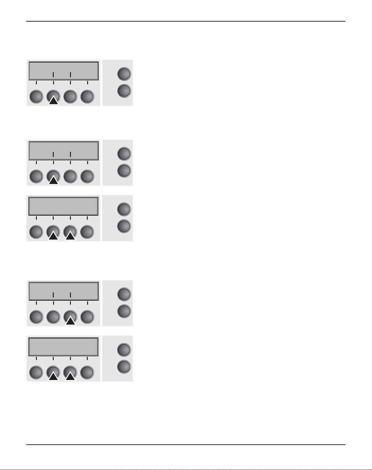
You can use the CPI (Character Per Inch) key in setup mode to sel-
ect the number of characters per inch to be printed. You can use the
Font key to select resident fonts.
Press the Setup key, then the Char (4) key.
Press the CPI (4) or Font (1) key (in our example, press CPI).
Use the < (2) or > (3) key to set the desired character density. Confirm the selection by pressing the Set (1) key.
You can cancel the selection and leave the setting unchanged by
pressing the Exit (4) key.
ROMAN NLQ
Set < > Exit
3
21
4
Adjust Paperway
Menu Char
3
21
4
Online
Setup
Online
Setup
If you pressed the Font (1) key, use the < (2) or > (3) key to select
the desired font. Confirm the selection by pressing the Set (1) key.
You can cancel the selection and leave the setting unchanged by
pressing the Exit (4) key.
Press the Setup key. The printer returns to the initial status.
It is also possible to press the Online key. The printer then changes
directly to online mode.
The selection made will not be retained after switching off the
printer. For more details on how to set the character density
and fonts permanently, please refer to the chapter Setting cha-
racter density (CPI) (page 50) and Selecting font (Font) (page 49).
29
Page 40

Paper handling User guide
Loading paper Your printer can process both fanfold paper and single sheets. For
informations on allowable paper formats, refer to the section Paper
specifications (page 114).
Only use dust-free or low-dust paper. Many paper qualities are
suitable for this printer. For more information, please refer to
Fanfold paper
the section Paper specifications
Remove the paper support for single sheets.
Make sure that the printer is set for fanfold paper printing. If necessary, change the paper
type (see Changing the paper type
nep
o
otllu
p
(page 114).
(page 27).
nepootllup
Open the right and left tractor flaps.
You may also want to remove the bottom cover
in order to facilitate loading the fanfold paper.
However, you can also feed paper to the tractor
with the bottom cover mounted.
30
Page 41

User guide Paper handling
Insert fanfold paper into the left-hand tractor.
Make sure that at least three paper transport
holes are positioned on the tractor pins.
Close the tractor flap.
Open the coloured latch lever and align the
tractor so that the first printing position on the
paper matches the X mark on the printer hou-
sing.
Lock the lever again.
Align the right-hand tractor to the width of the
paper and insert the paper.
Make sure that it is inserted by the
same length as on the left-hand
tractor in order to avoid any paper
jam.
31
Page 42

Paper handling User guide
Close the tractor flap and slide the tractor to the
right until the paper is slightly tensioned.
Do not tension the paper excessively to avoid
tearing the perforation holes; do not allow excessive slack since in this case the paper will
bulge and there may be problems in the feeding
process.
32
Then lock the tractor.
Page 43

User guide Paper handling
Make sure that the paper stack is aligned in
parallel to the printer and that the paper supply
cannot be obstructed.
Online Tractor1
Load
3
21
4
Online
Setup
Lower the front cover.
Switch the printer on. The active paper source (Tractor1) appears
in the display. The paper is automatically loaded when the printer is
in online mode and receives data from the computer.
Press the Load (4) key only to load paper before starting the
printout.
33
Page 44

Paper handling User guide
Single sheets
If required, install the paper support. Make sure
that the printer is set to single sheet mode. If
necessary, change the paper type, see
Changing the paper type
Press the latch at the middle of the front cover.
The single sheet input tray opens downwards.
(page 27).
Align the left paper guide with the mark on the
left of the single sheet input tray marking the
first printing position.
Adjust the right paper guide to the width of the
paper used.
34
Page 45

User guide Paper handling
Online
Setup
2
1
3
4
Insert the single sheet into the input tray as far
as possible.
Online Single
Load
3
2
1
Press the Online key to set the printer to ready status. The sheet is
Online
4
Setup
automatically loaded when the printer is in online mode and receives
data from the computer.
Press the Load (4) key only to load paper before starting the
printout.
35
Page 46

Paper handling User guide
Paper transport Loaded paper (fanfold paper/single sheets) can be transported in
the printer in several ways.
Offline Tractor1
Park LF/FF
3
21
4
Online
Setup
Make sure that the printer is in offline mode; press the Online key,
if necessary.
` Key Park (1)
If fanfold paper is loaded in the printer, it is fed to the park position
or the tear position. If a single sheet is loaded, it is ejected.
` Key (2)
Short keypress: Paper is transported upwards step by step.
Long keypress: Continuous transport upwards.
` Key (3)
Short keypress: Paper is transported downwards step by step.
Long keypress: Continuous transport downwards.
` LF/FF key (4):
Short keypress: Line Feed (LF) is executed.
Long keypress: Form Feed (FF) is executed.
The maximum value of the paper return feed is 22 inches.
36
Page 47

User guide Paper handling
Moving the paper to the tear position
Online Tractor1
Tear
3
21
Tear position
Tractor1
3
21
Online Tear
Exit
3
21
Online
4
Setup
Online
4
Setup
Online
4
Setup
You can use the Tear key to move the paper to the tear position.
The tear edge is located at the front side of the paper output opening
(see Printer at a glance
(page 2).
Make sure that the printer is in online mode. If necessary, press the
Online key.
Press the Tear (4) key. The printer moves the perforation edge of
the fanfold paper to the tear edge.
The display alternates between…
and…
After having torn off the paper, press the Exit key. The printer re-
turns the paper to the printing position.
If a print job is active, the printer returns the paper automatically to
the printing position.
Make sure you tear the paper off straight, otherwise a paper
jam may occur.
Removing paper Never use force to remove the paper from the printer. Other-
STOP
wise the mechanical components may be damaged.
Make sure that the printer is in offline mode; press the Online key,
Offline Tractor1
Park Load
3
21
4
Online
Setup
if necessary.
Press the Park (1) key. If fanfold paper is loaded in the printer, it is
fed to the tear position. The text Tear paper off appears in the display.
Now remove the paper from the tractor. Then press any key. If a single sheet is loaded in the printer, it is ejected.
37
Page 48

Settings User guide
7
Settings
Setting the print head gap
Adjust Paperway
Menu Char
3
21
TOF
Head Tear
Online
4
Setup
Online
This section describes how to set the print head gap, the tear position and the first printing line.
The printer features automatic print head gap adjustment to the
thickness of the paper used. In setup mode, you can enter a correction value to modify the head gap determined automatically. This
correction is useful for modifying the appearance of the type face.
The AGA (automatic gap adjustment) function must be set to
On. For more detailed information, refer to the section Automa-
tic gap adjustment (AGA) (page 85).
Press the Setup key. The printer changes to setup mode.
Press the Adjust (2) key.
Press the Head (1) key.
3
21
Head= 0 *
Set < > Exit
21
4
3
4
Setup
Online
Setup
Use the < (2) or > (3) key to set the range within which the automatic
gap adjustment is to be corrected. You can select values in the range from -10 to +10.
Confirm the input by pressing the Set (1) key.
Press the Setup key. The printer returns to the initial status.
Negative values decrease the print head gap, positive values
increase it. Changing the automatically determined value may
have a strong effect on the printing quality.
The setting made will be retained after switching off the
printer.
38
Page 49

User guide Settings
Setting the tear position
Adjust Paperway
Menu Char
3
21
TOF
Head Tear
21
TearAdj= 00/72"*
Set < > Exit
21
4
3
4
3
4
Online
Setup
Online
Setup
Online
Setup
If the tear position of the paper is not aligned with the tear edge of
the printer, you can adjust it. Inserted paper needs to be torn off if
necessary and retracted to park position.
Press the Setup key. The printer changes to setup mode.
Press the Adjust (2) key.
Press the Tear (4) key.
The tear edge is located at the front side of the paper output opening
(see Printer at a glance
(page 2).
Press the < (2) or > (3) key to move the perforation to the desired
position. Confirm the input by pressing the Set (1) key. Confirm the
input again by pressing the Setup key. The printer is reset to the initial status.
The correction made – a maximum of approx. 1" (2.5 cm) in
each direction – will be retained after switching the printer off.
It can be set separately for each paper path.
Make sure that the set form length corresponds to the actual
length of the forms you are using.
39
Page 50

Settings User guide
First
Readjusted
12/72"
0–220/72"
Setting the first printing line (TOF)
Adjust Paperway
Menu Char
3
21
TOF
Head Tear
3
21
First printing line, default
0–220/72"
Readjusted rst printing line
Online
4
Setup
Online
4
Setup
You can use the TOF function for setting the position of the first printing line for each paper source and each menu individually.
Before using the TOF function (if fanfold paper is used), you
should first set the tear position; see Setting the tear position
(page 39).
Press the Setup key. The printer changes to setup mode.
Press the Adjust (2) key.
Press the TOF (3) key.
The paper is fed to the position where the bottom edge of the first printing line is aligned with
12/72"
the tear edge of the printer. The factory setting
for the first printing position (TOF) is 12/ 72"
(4,23 mm). This is equivalent to the second line
from the top.
FormAdj= 12/72"*
Set < > Exit
3
21
40
Press the < (2) or > (3) key to move the first printing line to the desi-
Online
4
Setup
red position. You can set values from 0 to 220/72" for fanfold paper
or for single sheets.
Confirm the input by pressing the Set (1) key. Press the Setup key.
The printer returns to the initial status.
The selection made will be retained after switching off the
printer.
Page 51

User guide The Menu
8
The Menu
Programming via the control panel
Apart from being able to control your printer via the applications software you use, you can also program the printer directly. There are
two programming options you can use:
` Programming via the control panel.
` Programming via the interface using Escape sequences or control
codes.
Settings made by escape sequences have priority over settings made in menu mode; therefore they will override these.
Informations on Escape sequences can be found in
Appendix C, Emulations
Programming via the interface gives you far greater freedom for designing your printed pages, however, it is also a more sophisticated
method and requires some experience with programming languages and printer control systems.
All programming via the interface is lost after you turn off the printer,
whereas the programming carried out using the control panel, is
saved and stored even after you turn off the printer.
(page 125).
Enabling access to menu mode
The menu can be locked by default to protect it from accidental or
unauthorised access.
Proceed as follows to release this lock temporarily.
1 Switch off the printer for approx. 5 seconds.
2 Switch the printer on again keeping the Setup key pressed.
For information on how to enable access permanently and
about the available settings, refer to the section Menu lock
(MenLock) (page 62).
Calling up the menu You can access the menu in the following way:
Adjust Paperway
Menu Char
3
21
4
Online
Setup
Press the Setup key. The printer switches to Setup mode. (The Setup mode can be selected both in the Online and Offline mode.)
To access the printer menu, press the key directly underneath the
word Menu (1).
41
Page 52

The Menu User guide
Menu configurations Every printer is shipped with factory default settings. Basic settings
such as emulation, character size, form length etc., which many applications make use of, are set. At the end of this chapter you will find
a menu printout (page 75
tings.
Your printer allows you to set and use five independent menu configurations. If one of your applications for example requires an IBM
printer while another program works better with an EPSON printer,
you can set an IBM emulation configuration with the desired settings, and set the second configuration as an EPSON emulation.
The active menu is always the one you used last. When you switch
on the printer for the very first time, menu no. 1 is loaded. Menu no.
1 only remains active until you load another menu. The last active
menu is stored even after the printer is switched off and is reloaded
automatically when the printer is switched on again.
For example, to change from menu no. 1 to menu no. 3:
) which shows you the printer’s default set-
Online Tractor1
Tear
3
21
4
Adjust Paperway
Menu Char
3
21
4
Print Menu
Back Next
3
21
4
Load Menu=1 *
Set Exit
3
21
4
Online
Setup
Online
Setup
Online
Setup
Online
Setup
Press Setup key.
Press Menu (1) key.
Press Menu (3) key.
Now the following message appears in the LC display:
Now press the < (2) or > (3) key repeatedly until Load Menu=3 ap-
pears.
Then select menu no. 3 as the current setting using the Set key (1).
The currently active setting is marked with an asterisk (
).
*
42
If changing menues it is possible that the printer initializes due
to different emulation settings.
Page 53

User guide The Menu
Menu handling You can navigate in the current menu using the four function and se-
lection keys arranged below the LC display field. Each function and
parameter displayed in the LCD is executed or selected by the corresponding key below, respectively. Usually two parameter groups
are combined at one level. In the following example, these are the
LPI and Skip parameter groups.
If you do not wish to change one of the two parameters you can either press the Next key (to access the two following parameter
groups in the menu), or you can press the Back key (to access the
two previous parameter groups in the menu).
If you want to change a setting, (e.g. the line density), then press the
LPI key (LPI = lines per inch) to access the actual parameter level.
The currently valid setting is marked by a
the current setting is 6 lpi). With the < and > keys you can view the
other parameters available for this setting.
Example:
back to the previous
parameter groups
6 LPI *
Set <>Exit
LPI Skip
Back Next
Skip = 0.0 Inch*
Set <>Exit
(in the example below
*
on to the next
parameter groups
Save settings Once the desired parameter is displayed on the LC display, you can
save it by pressing the Set key. The parameter is then set and the
printer automatically displays the parameter groups again. With the
Exit key you can leave the sublevel without saving your changes.
43
Page 54

The Menu User guide
Selecting the LC display language
Online Tractor1
Tear
3
21
Adjust Paperway
Menu Char
3
21
Online
4
Setup
Online
4
Setup
This section describes how to make settings in the menu, using the
selection of the national language as an example.
In this user guide all LC display messages are shown in english language. Your printer offers also the possibility to show the display
messages in German, French, Italian, Spanish or Turkish language.
This example shows how to change from the English language to
the German language. The same procedure applies to the other languages (French, Italian, Spanish and Turkish).
Select the Setup mode by pressing the Setup key.
Press the Menu key (1).
Setup mode and Menu mode may be disabled. Hold
down the Setup key while switching on the printer to
enable menu mode. If you want to enable access to this
mode permanently, you need to change the appropriate
setting in the menu; see Menu lock (MenLock)
(page 62).
Print Menu
Back Next
3
21
4
MenLock Language
Back Next
3
21
4
English *
Set < > Exit
3
21
4
Online
Setup
Online
Setup
Online
Setup
Press the Next key (4) several times until the display indicates Lan-
guage.
Press the Language key (3).
The display now changes to Parameter mode and indicates English
in the top line.
The lower line displays Set and Exit. The two arrows < (2) and > (3)
represent the symbols for parameter selection (“<” indicates descending and “>” ascending). Press the < (2) or > (3) key until the
desired language is displayed, in our example German.
44
Page 55

User guide The Menu
German *
Set < > Exit
3
21
4
Online
Setup
verifies this action.
You can exit Parameter mode without saving a setting by pressing
the Exit key (4), the old setting is retained.
After saving your setting (Set), the display in our example indicates
the following text:
Ges.Men Sprache
Save your selection by pressing the Set key (1). An acoustic signal
Rück Vor
3
21
Online
4
Setup
This setting is retained even after switching off your printer.
Terminating Setup mode Press either the Setup key to change into Offline mode or the On-
line key to change to Online mode.
45
Page 56

The Menu User guide
Menu structure The menu structure of your printer may be slightly different from the
example shown here, depending on the printer software.
MENU
Next
Back
Reset
Font
LPI
ESCChar
Bidir
MenuPrint
Quietm.
CPI
Skip
Emulate
I/OInterf.
Serial
Interf. Buffer
FFaftLC
LeftMrg
FFmode
Barcode
Paper
Single
ASF-R
4)
3)
Paphand
RightMrg
PapOpt
Barmode
Width
AutoTear
Trac1
ASF-F
3)
Baud Format
1)
Special
Protocol
DTR
CG-Tab CharSet
1) only if ENQ/STX, ETX/ACK or ACK/NAK protocol is selected
2) only with optional tractor
3) only with optional ASF (automatic single sheet feeder)
4) not installed on some models
Trac2
MenLock
Auto-CR
Country
2)
2)
Trac3
Language
Auto-LF
Sl.Zero
46
Page 57

User guide The Menu
Menu parameters The following section introduces and explains all the possible menu
settings.
Online Tractor1
Tear
3
21
Online
4
Setup
Adjust Paperway
Menu Char
3
21
Online
4
Setup
Printing out menu configurations (Print)
Print Menu
Back Next
3
21
Online
4
Setup
Press Setup key.
Press Menu (1) key.
Setup mode and Menu mode may be disabled. Hold
down the Setup key while switching on the printer to
enable menu mode. If you want to enable access to this
mode permanently, you need to change the appropriate
setting in the menu; see Menu lock (MenLock)
(page 62).
Prints the menu configurations using the active paper feed; see
Menu settings (example)
(page 75).
Press Print (2) key, to start the printout.
Loading menu configurations (Menu)
Print Menu
Back Next
3
21
LoadMenu=1 *
Set <>Exit
3
21
Online
4
Setup
Online
4
Setup
A menu is loaded, you can choose between five menus; see Menu
handling (page 43).
Press Menu (3) key.
Use the < (2) or > (3) key to select the desired setting.
Setting Options: Load Menu=1/2/3/4/5
Default Setting: Load Menu=1
Confirm the setting by pressing the Set key (1). Press the Next key
(4) to access the next group of parameters.
47
Page 58

The Menu User guide
Reset to default values (Reset)
Reset Quietm.
Back Next
3
21
Reset Menu1
No Yes
3
21
Online
4
Setup
Online
4
Setup
STOP
The current menu returns to the default values (factory settings).
Press Reset (2) key.
Press the No (1) or Yes (2) key to select the desired setting.
All manually altered settings in the current menu are lost when
it is reset to the default settings.
We therefore recommend that you print out the menu first.
Confirm the setting by pressing the Set key (1).
Quietmode (Quietm.) Switches between normal and quiet mode printing. For all printing
modes, the print-out is made with the bidirectional method in quiet
mode printing. In the first step the first row of pins is activated, during
the second step the second row is used.
Reset Quietm.
Back Next
3
21
4
Quietm. = Off *
Setze<>Exit
3
21
4
Online
Setup
Online
Setup
Press Quietm. (3) key.
Use the < (2) or > (3) key to select the desired setting.
Setting Options: Quietm. = On/Off
Default Setting: Off
Confirm the setting by pressing the Set key (1). Press the Next key
(4) to access the next group of parameters.
Please note that the activation of Quietmode decreases the
throughput.
48
Page 59

User guide The Menu
Selecting font (Font) This parameter selects the character style and its quality perma-
nently.
Font CPI
Back Next
3
21
4
Draft *
Set <>Exit
3
21
4
Online
Setup
Online
Setup
Press Font (2) key.
Use the < (2) or > (3) key to select the desired setting.
Setting Options: see table below
Default Setting: Draft
Character styles marked with an
I (for example Courier I LQ) are
IBM compatible fonts.
Fonts with the identifier PS in their name are proportional fonts
which use only the space actually required for the character width.
Example:
Roman NLQ:
Roman PS NLQ:
The abbreviation NLQ stands for Near Letter print quality, which
means that the printer works faster but with a slightly lower resolution. LQ stands for Letter Quality, which means that the resolution is
higher at the expense of a slightly slower speed.
Available fonts
HIGH SPEED
DRAFT*
DRAFT COPY
ROMAN NLQ
ROMAN LQ
ROMAN PS NLQ
ROMAN PS LQ
SANS SERIF NLQ
SANS SERIF LQ
S SERIF PS NLQ
S SERIF PS LQ
* scalable fonts (LQ2170 emulation)
PRESTIGE LQ
SCRIPT NLQ
SCRIPT LQ
COURIER NLQ
COURIER LQ
OCRB NLQ
OCRB LQ
OCRA NLQ
OCRA LQ
COURIER I NLQ
PRESTIGE NLQ
COURIER I LQ
COUR I PS NLQ
COUR I PS LQ
LQ ORATOR
NLQ ORATOR
LQ GOTHIC NLQ
GOTHIC LQ
ROMAN/T NLQ*
ROMAN/T LQ *
SANS SERIF/H NLQ*
SANS SERIF/H LQ*
Confirm the setting by pressing the Set key (1).
49
Page 60

The Menu User guide
Setting character density (CPI)
Font CPI
Back Next
3
21
10 CPI *
Set <>Exit
3
21
Online
4
Setup
Online
4
Setup
Sets the characters per inch (character pitch). The higher the parameter the smaller the character spacing.
Press CPI (3) key.
Use the < (2) or > (3) key to select the desired setting.
Setting Options: 5 CPI, 6 CPI, 7.5 CPI, 8.6 CPI, 10 CPI,
12 CPI, 15 CPI, 17.1 CPI, 20 CPI
Default Setting: 10 CPI
Confirm the setting by pressing the Set key (1). Press the Next key
(4) to access the next group of parameters.
Setting line spacing (LPI) Sets the lines per inch (line density). The higher the parameter the
smaller the line spacing (random LPI can be selected via the ESC
sequences).
LPI Skip
Back Next
3
21
4
6 LPI *
Set <>Exit
3
21
4
Online
Setup
Online
Setup
Press LPI (2) key.
Use the < (2) or > (3) key to select the desired setting.
Setting Options: 2 LPI, 3 LPI, 4 LPI, 6 LPI*, 8 LPI, 12 LPI
Default Setting: 6 LPI
Confirm the setting by pressing the Set key (1).
50
Page 61

User guide The Menu
Skiping perforation (Skip) Skips the perforation; 7 different values (in inches) can be defined.
LPI Skip
Back Next
3
21
Online
4
Setup
Skip= 0.0 Inch*
Set <>Exit
3
21
Online
4
Setup
Selecting start signal for escape sequence (ESCChar)
ESCChar Emulate
Back Next
Online
Press Skip (3) key.
Use the < (2) or > (3) key to select the desired setting.
Setting Options: 0.0 to 3.5 Inch in steps of 0.5 inch
Default Setting: 0.0 Inch
Confirm the setting by pressing the Set key (1). Press the Next key
(4) to access the next group of parameters.
Selects the start signal for control sequences. Setting ESC: Only
character Escape can be used. Setting ESC+$$: Character Escape
or alternatively two $ characters ($$) can be used. For more information see the section The $$ procedure
(page 126).
Press ESCChar (2) key.
3
21
4
Setup
ESCChar=ESC*
Set <>Exit
3
21
Online
4
Setup
Use the < (2) or > (3) key to select the desired setting.
Setting Options: ESC/ESC+$$
Default Setting: ESC
Confirm the setting by pressing the Set key (1).
51
Page 62

The Menu User guide
Selecting emulation (Emulate)
ESCChar Emulate
Back Next
3
21
EpsonLQ-2550 *
Set <>Exit
21
4
3
4
Online
Setup
Online
Setup
Selects the emulation. When a printer understands the control set
written for another printer type, it is said to emulate the other printer.
MTPL is also active in IBM or Epson emulation mode.
Press Emulate (3) key.
Use the < (2) or > (3) key to select the desired setting.
Setting Options: Epson LQ-2550, Epson LQ-2170,
IBM Propr. XL24, IBM ProXL24+AGM,
MTPL
Default Setting: Epson LQ-2550
If the printer is switched to online mode after changing the emulation, it performs a reset.
Confirm the setting by pressing the Set key (1). Press the Next key
(4) to access the next group of parameters.
Bidirectional printing (Bidir)
Bidir I/O
Back Next
3
21
Bidir=On *
Set <>Exit
3
21
Online
4
Setup
Online
4
Setup
Setting On: Printer prints in both directions (bidirectional).
Setting Off: Printer prints only in one direction (from left to right).
Press Bidir (2) key.
Use the < (2) or > (3) key to select the desired setting.
Setting Options: On/Off
Default Setting: On
Confirm the setting by pressing the Set key (1).
The setting On will not be overwritten by ESC sequences.
52
Page 63

User guide The Menu
Settings for interfaces (I/O) In this parameter group, you can choose various settings for the
printer interfaces. See also Interfaces
(page 145).
Bidir I/O
Back Next
3
21
4
Online
Setup
Press I/O (3) key.
Serial interface (Serial) This parameter group only is valid, if an optional serial interface
module is installed.
STOP
Serial Interf.
Back Next
3
21
4
Online
Setup
Press Serial (2) key.
Data transmission rate (Baud) Selects the data transmission rate (baud rate) (baud = bit per sec-
ond).
To ensure the proper functioning of serial data transfers, the serial settings of the printer and computer
(host) must coincide.
Baud Format
Back Next
3
21
4
Baud= 9600 *
Set <>Exit
3
21
4
Online
Setup
Online
Setup
Press Baud (2) key.
Use the < (2) or > (3) key to select the desired setting.
Setting Options: 600, 1200, 2400, 4800, 9600, 19200
Default Setting: 9600
Printer and computer must have the same baud rate.
Confirm the setting by pressing the Set key (1).
53
Page 64

The Menu User guide
Data format (Format) This parameter serves to define the number of data bits, the parity
check for received data bytes and the number of stop bits per data
byte.
Baud Format
Back Next
3
21
4
8bit No 1Stop*
Set <>Exit
3
21
4
Online
Setup
Online
Setup
Press Format (3) key.
Use the < (2) or > (3) key to select the desired setting.
Setting Options: see table below
Default Setting: 8 Bit No 1 Stop
1 number of data bits 2 parity test 3 number of stop bits
7 Bit No 2 Stop
7 Bit Even 1 Stop
7 Bit Odd 1 Stop
7 Bit Even 2 Stop
7 Bit Odd 2 Stop
7 Bit Mark 1 Stop
7 Bit Spc 1 Stop
7 Bit Mark 2 Stop
7 Bit Spc 2 Stop
8 Bit No 1 Stop
8 Bit No 2 Stop
8 Bit Even 1 Stop
8 Bit Odd 1 Stop
8 Bit Mark 1 Stop
8 Bit Spc 1 Stop
1 Sets the number of data bits: You can select 7 or 8.
2 The parity test for received data bytes can be selected. NO cau-
ses transmission in both directions without parity bit. If EVEN or
ODD is selected, the bytes are checked if they have even or odd
parity. The selection of MARK or SPACE causes a data byte
transmission with parity bit, but without checking the received data. Transmission data with parity bit is always marked with 1
(MARK) or 0 (SPACE).
3 Selects one or two stop bits per data byte.
Confirm the setting by pressing the Set key (1). Press the Next key
(4) to access the next group of parameters.
54
Page 65
User guide The Menu
Further Settings (Special) This parameter subgroup only appears if the serial port is used and
the ENQ/STX, ETX/ACK or ACK/NAK protocol is activated.
Special Protocol
Back Next
3
21
4
Online
Setup
Press Special (2) key.
Error handling (ErrMode) On replaces the incorrect character with ?, Off deletes the entire
block.
ErrMode Blockend
Back Next
3
21
4
ErrMode=Off *
Set <>Exit
3
21
4
Online
Setup
Online
Setup
Press ErrMode (2) key.
Use the < (2) or > (3) key to select the desired setting.
Setting Options: On/Off
Default Setting: Off
Confirm the setting by pressing the Set key (1).
Block end character (Blockend) End-of-block character definition; On: LF, FF, CR, VT, ETX, DEL;
Off: ETX, DEL.
ErrMode Blockend
Back Next
3
21
4
Online
Setup
Press Blockend (3) key.
Use the < (2) or > (3) key to select the desired setting.
Blockend=Off *
Set <>Exit
3
21
4
Online
Setup
Setting Options: On/Off
Default Setting: Off
Confirm the setting by pressing the Set key (1). Press the Next key
(4) to access the next group of parameters.
55
Page 66

The Menu User guide
Signal feedback (Remote) Signal feedback; On = RDY/BUSY available, Off = No RDY/BUSY
control.
Remote Handthr
Back Next
3
21
4
Remote=Off *
Set <>Exit
3
21
4
Online
Setup
Online
Setup
Press Remote (2) key.
Use the < (2) or > (3) key to select the desired setting.
Setting Options: On/Off
Default Setting: Off
Confirm the setting by pressing the Set key (1).
Transparence (Handthr) Affects the transparence of control sequences and block acknowl-
edgement, depending on the selected protocol.
Remote Handthr
Back Next
3
21
4
Online
Setup
Press Handthr (3) key.
Handthr=Off *
Set <>Exit
3
21
4
Online
Setup
Use the < (2) or > (3) key to select the desired setting.
Setting Options: On/Off
Default Setting: Off
Confirm the setting by pressing the Set key (1). Press the Next key
(4) to leave the parameter subgroup Special.
56
Page 67

User guide The Menu
Protocol (Protocol) This parameter serves to select the type of protocol, i.e. a certain set
of rules and procedures for ensuring error-free data exchanges between computer and printer.
Special Protocol
Back Next
3
21
4
Online
Setup
Press Protocol (3) key.
Use the < (2) or > (3) key to select the desired setting.
XON/XOFF *
Set <>Exit
3
21
4
Online
Setup
Setting Options: XON/XOFF, Robust XON/XOFF,
ENQ/STX, ETX/ACK, ACK/NAK
Default Setting: XON/XOFF
Confirm the setting by pressing the Set key (1). Press the Next key
(4) to access the next group of parameters.
Signal Processing (DTR) Defines the conductor to which the DTR signal is connected
(DTR = Data Terminal Ready).
DTR
Back Next
Online
Press DTR (2) key.
3
21
4
DTR=DTR *
Set <>Exit
3
21
4
Setup
Online
Setup
Use the < (2) or > (3) key to select the desired setting.
Setting Options: DTR/READY
Default Setting: DTR
DTR=DTR: DTR signal is assigned to DTR line.
DTR=READY: READY signal is assigned to DTR line.
DTR = Pin 20 on 25-pin female RS232 connector.
DTR = Pin 4 on 9-pin female RS232 connector.
Confirm the setting by pressing the Set key (1). Press the Next key
(4) to access the next group of parameters.
57
Page 68

The Menu User guide
Selecting interface (Interf.) Selects the interface. Printer is configured either for parallel, Ether-
net or optional serial connection or in automatic change for the parallel or the optional serial interface (Shared).
Serial Interf.
Back Next
3
21
4
Interf.= Share*
Set <>Exit
3
21
4
Online
Setup
Online
Setup
Press Interf. (3) key.
Use the < (2) or > (3) key to select the desired setting.
Setting Options: Share, Parallel, Serial
Default Setting: Share
Interf.=Share: Printer switches automatically between parallel and
optional serial interface.
Interf.=Parallel: Printer using parallel interface.
Interf.=Serial: Printer using serial interface.
Confirm the setting by pressing the Set key (1). Press the Next key
(4) to access the next group of parameters.
Interface buffer (Buffer) Selects the size of the interface buffer.
Buffer
Back Next
3
21
4
Buffer=128 KB *
Set <>Exit
3
21
4
Online
Setup
Online
Setup
Press Buffer (2) key.
Use the < (2) or > (3) key to select the desired setting.
Setting Options: 0 – 128 KB
Default Setting: 128 KB
If buffer = 0 KB and the serial interface is selected, or if
the setting “Share” is active, the actual buffer size will
be 512 bytes.
Confirm the setting by pressing the Set key (1). Press the Next key
(4) to leave the parameter group Interf.. Press the Next key (4)
again to access the next group of parameters.
58
Page 69

User guide The Menu
Ethernet interface (ETH-EXT) option
ETH-EXT
Back Next
3
21
Online
4
Setup
Selecting character set (CG-Tab)
CG-TabCharset
Back Next
3
21
Online
4
Setup
In this parameter group you can choose settings for the optional external Pocket Ethernet interface.
Press ETH-EXT (3) key.
For more informations refer to the Installation CD-ROM
of the interface.
Only available for Epson LQ 2550/LQ2170 emulation. Either the Epson character set Italics or the IBM graphics character set or a DLL
(download) character set, as defined before, can be activated in the
code range from hex. A0 to hex. FE.
Press CG-Tab (2) key.
CG-Tab=Graphic *
Use the < (2) or > (3) key to select the desired setting.
Set <>Exit
3
21
4
Online
Setup
Setting Options: Graphic, DLL, Italic
Default Setting: Graphic
Confirm the setting by pressing the Set key (1).
IBM character set (CharSet) Selects the IBM standard characters or the extended IBM charac-
ters.
CG-TabCharSet
Back Next
3
21
Online
4
Setup
Extended*
Set <>Exit
3
21
Online
4
Setup
Press CharSet (3) key.
Use the < (2) or > (3) key to select the desired setting.
Setting Options: Standard/Extended
Default Setting: Extended
Confirm the setting by pressing the Set key (1). Press the Next key
(4) to access the next group of parameters.
59
Page 70

The Menu User guide
National character set (Country)
Country Sl.Zero
Back Next
3
21
Online
4
Setup
E-USASCII *
Set <>Exit
3
21
Online
4
Setup
Slashed zero (Sl.Zero)
Selects the national character set. These character sets can be
used according to the selected emulation.
The character sets are not necessarily available for all fonts; see
also Available character sets and fonts
(page 122).
Press Country (2) key.
Use the < (2) or > (3) key to select the desired setting.
Setting Options: See Available character sets and fonts
(page 122)
Default Setting: E-US ASCII
Confirm the setting by pressing the Set key (1).
Selects if normal zero (0) or the slashed zero (Ø) is printed.
Country Sl.Zero
Back Next
3
21
4
Sl.Zero=Off *
Set <>Exit
3
21
4
Online
Setup
Online
Setup
Press Sl.Zero (3) key.
Use the < (2) or > (3) key to select the desired setting.
Setting Options: Off/On
Default Setting: Off
Confirm the setting by pressing the Set key (1). Press the Next key
(4) to access the next group of parameters.
60
Page 71

User guide The Menu
Automatic carriage return (Auto-CR)
Auto-CRAuto-LF
Back Next
3
21
Online
4
Setup
Auto-CR=On *
Set <>Exit
3
21
Online
4
Setup
Automatic line feed (Auto-LF)
Auto-CRAuto-LF
Back Next
Online
Switches the automatic carriage return on or off after receiving the
signal LF (lne feed).
Press Auto-CR (2) key.
Use the < (2) or > (3) key to select the desired setting.
Setting Options: Off/On
Default Setting: On
Confirm the setting by pressing the Set key (1).
Switches the automatic line feed (LF) on or off after receiving the
signal CR (carriage return).
Press Auto-LF (3) key.
3
21
4
Auto-LF=On *
Set <>Exit
3
21
4
Setup
Online
Setup
Use the < (2) or > (3) key to select the desired setting.
Setting Options: Off/On
Default Setting: Off
Confirm the setting by pressing the Set key (1). Press the Next key
(4) to access the next group of parameters.
61
Page 72

The Menu User guide
Menu lock (MenLock) With MenLock = Off, all functions and settings are accessible with-
out restriction in Online, Offline and Setup mode.
If MenLock = Menu is activated, all functions and settings are still
accessible in Online and Offline mode, however, in Setup mode you
can only access the parameter groups Adjust (setting the print head
gap [Head], top of form [TOF] and tear position [Tear]), Paperway
(setting the paper path), Font (setting the font) and the character
spacing (CPI), while access to Menu mode (Menu key) is disabled.
If you select MenLock = All, you can access the Online/Offline,
Load/Park, Paper and Paper Feed (LineFeed/Form Feed, / )
functions in Online and Offline mode while Setup mode is disabled.
In this case, the Setup menu can only be called up by holding the
key Setup while switching on the printer.
MenLockLanguage
Back Next
3
21
4
Online
Setup
Press MenLock (2) key.
Use the < (2) or > (3) key to select the desired setting.
MenLock=Menu *
Set <>Exit
3
21
4
Online
Setup
Setting Options: Off, Menu, All
Default Setting: Menu
Confirm the setting by pressing the Set key (1).
Language (Language) The menu can be shown in six languages on the LC display.
MenLockLanguage
Back Next
3
21
4
Online
Setup
Press Language (3) key.
English *
Set <>Exit
3
21
62
Use the < (2) or > (3) key to select the desired setting.
Online
4
Setup
Setting Options: English, German, French, Italian, Spanish,
Turkish
Default Setting: English
Confirm the setting by pressing the Set key (1). Press the Next key
(4) to access the next group of parameters.
Page 73

User guide The Menu
Paper parameters (Paper) Selects the paper parameters Formlen (form length), FormAdj (first
printing position) and Head (printhead gap, only if AGA=Off) sepa-
rately for each paper source in the current menu.
Non-installed and with the parameter PapOpt activated options cannot be selected.
Paper AutoTear
Back Next
3
21
4
Single Trac1
Back Next
3
21
4
Online
Setup
Online
Setup
Press Paper (2) key.
You can now choose between the following paper options:
` Single
` Tractor 1
` ASF-F (Single sheet feeder front, option)
` ASF-R (Single sheet feeder rear, option)
` Tractor 2 (front, option)
` Tractor 3 (rear, option)
Select the desired paperway, in our example Single (2). Press Next
(4) key, to proceed to the installed optional paperways.
Form length (Forml) You can define the form length in one of two ways: via the number
of lines or via standard formats (e.g. DIN A4).
Forml FormAdj
Back Next
3
21
4
Lines Standard
Back Next
3
21
4
Online
Setup
Online
Setup
Press Forml (2) key.
If you wish to define the form length via a line format, press Line (2)
key.
63
Page 74

The Menu User guide
6 LPI =72 *
Set <>Exit
3
21
4
Lines Standard
Back Next
3
21
4
No Format *
Set <>Exit
3
21
4
Online
Setup
Online
Setup
Online
Setup
Use the < (2) or > (3) key to select the desired setting.
Setting Options: 6 bis 144
Default Setting: 72
Sets the form length via line formats. Please note that the adjustment in Lines depends on the selected LPI. For example 8 LPI at a
selected line number of 96 lines results in a formlength of 12 inches
(96 lines/[8lines/inch]) = 12 inches). The selectable range is between 3 and 21 inches, i.e. for 2 LPI from 6 to 42 lines and for 12 LPI
from 24 to 262 lines.
If the form length is set it will not be changed by changing the LPI
later on.
Confirm the setting by pressing the Set key (1).
If you wish to define the form length via standard formats, press
Standard (3) key.
Use the < (2) or > (3) key to select the desired setting.
Setting Options: DIN A3, DIN A4, DIN A5, DIN B5, DIN B6,
Exective 10.5", Letter 11", Legal 14", No Format
Default Setting: No Format
Selects the form length by standard formats. Using Standard, different paper formats can be selected directly, e.g. DIN A4, Legal, Letter.
The LC display indicates No format if a value is selected by the Line
function or ESC sequences, which does not correspond to a standard format.
Confirm the setting by pressing the Set key (1).
64
Page 75

User guide The Menu
First printing position (FormAdj) Sets the first print position of a form in n/72 inch, separately adjust-
able for each paper path.
The settings made here reduce the height of the printable area.
Forml FormAdj
Back Next
3
21
FormAdj= 12/72 *
4
"
Set <>Exit
3
21
4
Online
Setup
Online
Setup
Press FormAdj (3) key.
Use the < (2) or > (3) key to select the desired setting.
Setting Options: 0/72" bis 220/72"
Default Setting: 12/72"
Confirm the setting by pressing the Set key (1). Press the Next key
(4) to access the next group of parameters.
An alternative notation for FormAdj is TOF (Top Of Form).
65
Page 76

The Menu User guide
Printhead gap manually (Head) This parameter is ignored if the automatic gap adjustment (AGA) is
activated; see Automatic gap adjustment (AGA)
(page 85).
Adjusts the printhead gap manually; separately adjustable for each
paper path.
Head
Back Next
3
21
4
Head= 18 *
Set <>Exit
3
21
4
Online
Setup
Online
Setup
Press Head (2) key.
Use the < (2) or > (3) key to select the desired setting.
Setting Options: 0 to 100
Default Setting: 18
Select the Head = 18 parameter for normal paper. Use a greater distance for thicker paper.
Recommended values for the print head gap:
thin thick
18 26 34 42 50 58
If you change this value, this may affect the print quality.
If the printout shows signs of smudging, we recommend that
you increase the print head gap.
Confirm the setting by pressing the Set key (1). Press the Next key
(4) to access the next group of parameters.
66
Page 77
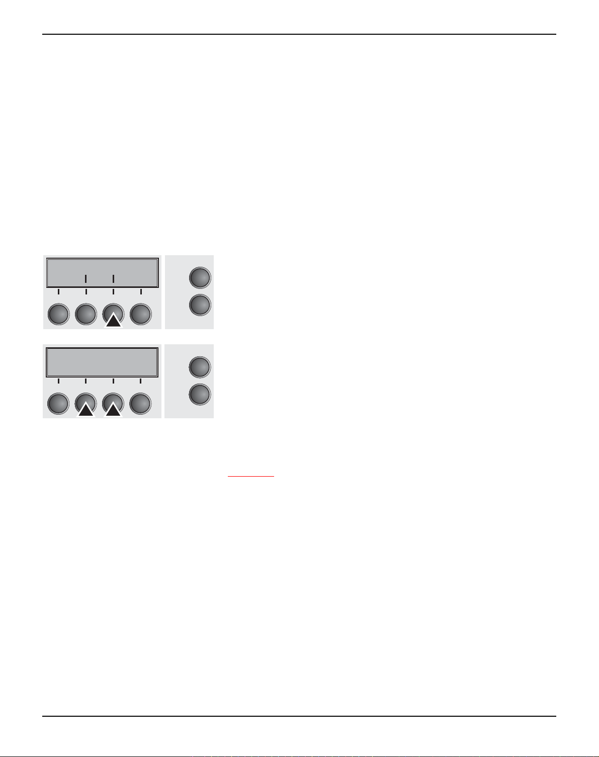
User guide The Menu
View and tear position (AutoTear)
Paper AutoTear
Back Next
3
21
ViewTear=Off *
Set <>Exit
3
21
Online
4
Setup
Online
4
Setup
The auto tear function or the auto view function can be selected as
desired.
When auto view is switched on, the last printed text is visible. As
soon as data is received the paper moves to the “normal” print position. After printing the printer waits for the given interval to bring the
paper once more to the auto view position.
The paper is in the tear off position when auto tear is switched on,
the perforation of the paper is positioned at the tear off edge of the
printer. If data is received, the paper returns to the normal print position. After printing, the printer waits for the given interval to bring
the paper once more to the tear off position. If the tear off edge does
is not aligned with the perforation of the paper then this can be corrected.
Press AutoTear (3) key.
Use the < (2) or > (3) key to select the desired setting.
Setting Options: ViewTear=Off,
View=1s/3s/6s
Tear=1s/3s/6s
Tear at TOF
Default Setting: ViewTear=Off
If the parameter View Tear = Off is set, the paper can still be
brought into a View or Tear position via a specific sequence (see
page 133
) or the Tear key.
If the parameter Tear at TOF is set, the paper perforation is automatically positioned at the tear off edge as long as the current print
position TOF is activated. Feeding takes place after approx. 1.5 seconds (hold time). If any data is received during this period of time the
paper is not positioned at the tear off edge. With this function it must
be noted that the printer may only be switched off when the print position is at TOF.
Confirm the setting by pressing the Set key (1). Press the Next key
(4) to access the next group of parameters.
67
Page 78

The Menu User guide
Line length (Width) Selects the line length in inches. With the setting of 8 Inch, the print-
er operates like a printer with a width of only 8 inches.
Width
Back Next
3
21
4
Width=13.6Inch*
Set <>Exit
3
21
4
Online
Setup
Online
Setup
Press Width (2) key.
Use the < (2) or > (3) key to select the desired setting.
Setting Options: 8 Inch, 13.2 Inch, 13.6 Inch
Default Setting: 8 Inch (narrow printer)
13.6 Inch (wide printer)
Confirm the setting by pressing the Set key (1). Press the Next key
(4) to access the next group of parameters.
Barcode (Barcode) With this function selected it is posible to print different barcodes and
LCP (Large Character Printing).
Barcode Barmode
Back Next
Online
Press Barcode (2) key.
3
21
4
Barcode=Off *
Set <>Exit
3
21
4
Setup
Online
Setup
Use the < (2) or > (3) key to select the desired setting.
Setting Options: On/Off
Default Setting: Off
The definition and activation is performed by special sequences
through the interface. Since this selection is possible for all emulations it must be noted that conflicts in sequence conformity with the
selected emulation may occur. For this reason the barcode function
can also be switched on and off by MTPL sequences. (The possible
barcodes, LCP characters and the operation of these functions are
described in the Barcode Programmer’s Application Manual
).
Confirm the setting by pressing the Set key (1).
68
Page 79

User guide The Menu
Normal characters and barcode (Barmode)
Barcode Barmode
Back Next
3
21
Secured*
Set <>Exit
3
21
Online
4
Setup
Online
4
Setup
Allows printing of normal characters on the left and right of the barcode.
Press Barmode (3) key.
Use the < (2) or > (3) key to select the desired setting.
Setting Options: Secured/Unsecured
Default Setting: Unsecured
In secured mode, the space which the barcode characters require
is “protected”. In each line, other barcode or normal characters can
also be printed. These additional characters are printed in the line
currently being printed and and in the subsequent lines, without affecting the barcode which is already being printed. Consequently,
normal characters can be printed in every line to the right or left of
the barcode.
In unsecured mode, the required paper transport for printing barcodes and LCP is carried out automatically, it is not possible to print
more than one line of normal characters in the barcode line. All characters in the mixed line are printed such that their bottom edges are
in a straight line. This function may be switched on and off by sequences.
This function can be activated/deactivated by sequences.
Confirm the setting by pressing the Set key (1). Press the Next key
(4) to access the next group of parameters.
69
Page 80

The Menu User guide
Form feed mode (FFmode) Specifies whether a form feed is to be performed when the paper
reaches the top print line.
FFmode PapOpt
Back Next
3
21
4
FFmode=Off *
Set <>Exit
3
21
4
Online
Setup
Online
Setup
Press FFmode (2) key.
Use the < (2) or > (3) key to select the desired setting.
Setting Options: On/Off
Default Setting: Off
FFmode = On: If the paper is positioned in the first printing line
(TOF), form feeds will be ignored.
FFmode = Off: Form feed will be performed in all cases.
Confirm the setting by pressing the Set key (1).
70
Page 81

User guide The Menu
Setting and activating options (PapOpt)
For setting the optional automatic sheet feeders (ASFs) and optional
tractors; see Paperway
(page 4). Also regulates the activation of
ASFs and/or optional tractors.
FFmode PapOpt
Back Next
3
21
4
Online
Setup
Press PapOpt (3) key.
Activation of tractors (AutoTra) This parameter only appears if at least one optional tractor is in-
stalled. It regulates the activation of tractors when there is no more
paper left in one of them.
AutoTraAutoASF
Back Next
3
21
4
AutoTra=Off *
Set <>Exit
3
21
4
Online
Setup
Online
Setup
Press AutoTra (2) key.
Use the < (2) or > (3) key to select the desired setting.
Setting Options: Off/T1=T2
Default Setting: Off
If an optional tractor is not installed, Off is displayed (factory default). If an optional tractor is installed and the Off parameter is activated, only the selected tractor is supported (either via the menu or
an ESC sequence). If the selected tractor is out of paper, printing
stops.
If an optional tractor is installed and you select T1=T2, the printer will
load paper from the other tractor if the selected one is empty.
Confirm the setting by pressing the Set key (1).
71
Page 82

The Menu User guide
Activation of automatic sheet feeder (AutoASF)
AutoTraAutoASF
Back Next
3
21
Online
4
Setup
AutoASF=Off *
Set <>Exit
3
21
Online
4
Setup
This parameter only appears if an optional automatic sheet feeder is
installed. This feature is only available for the option
ASF-R. It regulates the activation of automatic sheet feeders when
there is no more paper left in one of them.
Press AutoASF (3) key.
Use the < (2) or > (3) key to select the desired setting.
Setting Options: Off/On
Default Setting: Off
If an ASF is installed and the Off parameter is activated, only the se-
lected source is supported (either via the menu or an ESC sequence). If the selected paper source is empty, printing stops.
If an ASF is installed and you select On, the printer will load paper
from the other source if the selected one is empty.
Confirm the setting by pressing the Set key (1). Press the Next key
(4) to access the next group of parameters.
Setting the left margin (LeftMrg)
LeftMrg RightMrg
Back Next
3
21
LeftMrg=0/10 *
Set < > Exit
3
21
Online
4
Setup
Online
4
Setup
The left print margin can be set to a fixed value.
Press LeftMrg (2) key.
Use the < (2) or > (3) key to select the desired setting.
Setting Options: 0–78/10“ (narrow printer)
0–134/10“ (wide printer)
Default Setting: 0/10“
The value may not exceed the RightMrg value.
Confirm the setting by pressing the Set key (1).
72
Page 83

User guide The Menu
Setting the right margin (RightMrg)
LeftMrg RightMrg
Back Next
3
21
Online
4
Setup
RightMrg=136/10*
Set < > Exit
3
21
Online
4
Setup
Local copy (screen print) from a Coax or Coax/IPDS (FFaftLC)
The right print margin can be set to a fixed value.
Press RightMrg (3) key.
Use the < (2) or > (3) key to select the desired setting.
Setting Options: 2–80/10“ (narrow printer)
2–136/10“ (wide printer)
Default Setting: 80/10“ or 136/10“
The value may not fall below the LeftMrg value.
Confirm the setting by pressing the Set key (1). Press the Next key
(4) to access the next group of parameters.
This is a feature of the IBM compatible Coax/Twinax and IPDS Interface (option). Local Copy is a Screen Print from an AS400 or
Mainframe. This is to ensure maximum compatibility.
FFaftLC Paphand
Back Next
3
21
4
FFaftLC=ON *
Set < > Exit
3
21
4
Online
Setup
Online
Setup
Press FFaftLC (2) key.
Use the < (2) or > (3) key to select the desired setting.
Setting Options: Off/On
Default Setting: On
Confirm the setting by pressing the Set key (1).
73
Page 84

The Menu User guide
Enable/Disable Paper Handling Features (Paphand)
FFaftLC Paphand
Back Next
3
21
Paphand=ON *
Set < > Exit
3
21
Online
4
Setup
Online
4
Setup
In the advanced menu, Paper handling (Paphand), are several possibilities to improve the paper handling of the printer even with critical paper and forms. This menu parameter enables or disables the
set features in the current active menu.
Press Paphand (3) key.
Use the < (2) or > (3) key to select the desired setting.
Setting Options: Off/On
Default Setting: On
Confirm the setting by pressing the Set key (1).
74
Page 85

User guide The Menu
Menu settings (example)
75
Page 86

The Menu User guide
76
Page 87
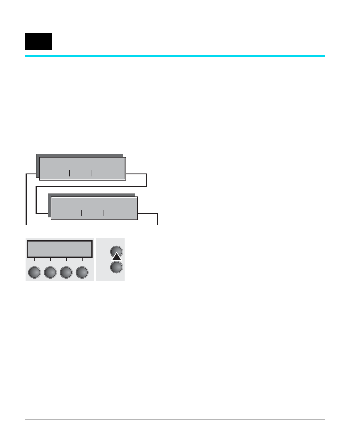
User guide Advanced menu
9
Advanced menu
The advanced menu consists of test functions and advanced settings.
Test functions Various tests to check proper operation of the printer are available
at any time. With these tests it is possible to check the print quality,
proper operation of the printhead and the mechanics, as well as efficient data transmission from the computer to the printer.
The extended menu contains three test functions (ASCII 80,
ASCII 136 (only wide printer), H-Dump).
ASCII80 ASCII136
W ASCII test with 80 or 136 characters per line.
Back Next
H-Dump
W Interface test (H-Dump)
Back Next
Testmode
Initializing ...
3
21
4
Online
Setup
Enter advanced menu mode by pressing the key Online while
switching on the printer.
The display shows Test mode for approx. 1 second and then automatically changes to display ASCII 80 ASCII 136.
77
Page 88

Advanced menu User guide
Printer self-test (Rolling ASCII)
Testmode
Initializing ...
3
21
ASCII80 ASCII136
Back Next
3
21
Adjust Paperway
Menu Char
3
21
To check operational readiness, your printer contains a self-test routine which allows testing of the printer configuration, the print quality
and correct operation of your printer.
Before performing a self-test, your printer must be switched off. En-
Online
4
Setup
sure that paper is inserted. Keep the key Online pressed while
switching on the printer, until Testmode appears on the display.
Press the soft key for the ASCII 80 format (corresponds to Legal
Online
4
Setup
Portrait) or for ASCII 136 (Double or Legal Landscape). The display
will indicate Test mode Off.
Press the Online key, to start the test.
It is also possible to change to Setup mode when you are in Rolling
Online
4
Setup
test mode if you want to change the configuration for the test printout.
To do this, press the key Setup. The printer then changes to Setup
mode and the first of the main levels is then displayed.
Program your printer in the usual way for the test printout to change
the parameters. See section Programming via the control panel
(page 41).
Some changes in menu mode may cOffe the printer to rOnitialize; in
this case the Rolling ASCII test is aborted.
By pressing the key Setup you exit Setup mode and the printer
once again returns to Rolling ASCII test mode test mode.
Testmode Off is displayed. Press the key Online, the test printout
starts.
The self-test can be interrupted by pressing the key Online which
will stop printing and put the printer into Offline status.
Before you begin printing, you can adjust the paper for the printout
with soft keys
and .
78
Page 89

User guide Advanced menu
Example of an ASCII test printout
If you selected a proportional font (PS font) , the printed length
of the lines varies.
This test can also be used to determine and set the optimal
printhead gap (see the section Setting the print head gap
(page 38).
Exiting Rolling ASCII test mode The self-Rolling ASCII test mode test mode can only be terminated
by switching off your printer. For this operation the printer must be
Offline.
If you want to stop the test printout before switching off the
printer, press the key Online.
79
Page 90

Advanced menu User guide
Interface test (Hex-Dump)
With the interface test (Hex-Dump/H-Dump) you can test data transmission from the computer to the printer. During this test, the data
from the computer is printed out in two columns. The text in the left
column is printed in hexadecimal format and in the right column in
ASCII format.
Printout in Hex-Dump Put the printer into advanced menu mode by pressing the key On-
line while switching on the printer.
Press the key Online until Test mode is shown on the display.
The display shows Test mode for approx. 1 second and then automatically changes to display ASCII 80 ASCII 136 (only wide printer).
Press the key Next (4), the display shows the next menu level.
ASCII80 ASCII136
Back Next
3
21
Online
4
Setup
If you press the key H-Dump (2) you select the H-Dump mode and
H-Dump
Back Next
Online
Offline H-Dump is shown on the display.
3
21
4
Offline H-Dump
Park LF/FF
3
21
4
Setup
Online
Setup
Put the printer into Online H-Dump mode by pressing the key On-
line. The printer is now ready to receive data from the computer and
to print it out in hexadecimal format. The printed data can now be analyzed and evaluated.
Example of a Hex-Dump printout
80
After the transmission you must switch the printer to Offline.
Any remaining data left in the interface buffer is then printed.
Page 91

User guide Advanced menu
Terminating Hex-Dump Hex-Dump mode can only be terminated by switching off the printer.
If you want to stop the Hex-Dump printout before switching off
the printer, press the key Online and then the key LF/FF (4)
once.
81
Page 92

Advanced menu User guide
Advanced settings In the advanced menu, there are other settings available besides the
test functions.
` With the function PMS you have the possibility of activating the au-
tomatic paper motion sensor (PMS) in case of a paper jam.
` With the functon Forml you can adjust the form length.
` The function AGA switches the automatic printhead gap function on
or off.
` You can also select adjustments which facilitate handling paper
which may cOffe problems in printing due to its structure (Paphand).
` The CX-bid menu option controls the bidirectionality of the parallel
interface.
` With the function Wrap, you can set line wrap and with the function
Sound beep at paper end.
` The Single menu option can be used to deactivate the single sheet
func-tion (for printers without single sheet feeder).
` The function Pap.back allows printing on paper with a dark back.
` You can use the HvyForm function to set the print head to print the
same line twice at double strike force in order to ensure that copy
paper produces optimum results even if it has a faint copying effect.
` If the parameter Sleepmod is activated, the printer switches to en-
ergy-saving mode after 30 seconds of inactivity.
` With the SerialN function you have the possibility to change the se-
rial number of the printer.
` With the AssetN function you have the possibility to change the as-
set number of the printer.
` The GrSpeed function allows improved graphic speed.
` The function GrFreq has an effect on graphic and barcode print. A
lower print speed may affect the printout quality positive.
` With Jobcntl you can activate the PJL functionality. Therefore a
TallyCom III Ethernet Interface (or compatible) must be installed.
` HS-Draft allows a higher print speed for 17.1 and 20 cpi with a lower
print density.
82
Page 93

User guide Advanced menu
H-Dump
Back Next
Forml AGA
Back Next
Paphand CX-bid
Back Next
Wrap Sound
Back Next
Single Pap.back
Back Next
W Interface test
W Setting default form length and the Automatic Gap Adjustment
for the print head
W Settings to facilitate handling paper of poor quality and the
parallel interface
W Setting line wrap and sound when paper empty
W Single does not apply to this printer
Setting for printing on paper with dark back
Einzel Pap.art
Back
Back Next
HvyForm
SleepMod
Back Next
SerialN AssetN
Back Next
GrSpeed GrFreq
Back Next
Jobcntl Hs-Draft
Back Next
W To print copy paper
W Energy save mode
W Changing serial number and asset
number of the printer
W Allowas improved graphic speed
Improves the graphic and barcode
print quality
W Activates the PJL functionality
Increases the print speed for
17.1 and 20 cpi
83
Page 94

Advanced menu User guide
Enter Extended menu mode by pressing the key Online while
switching on the printer.
Testmode
Initializing ...
3
21
4
Online
Setup
matically changes to display ASCII 80 ASCII 136 (only wide printer).
Form length (Forml) The Formlen function allows you to set the basic form length to
meet your requirements. 11 inches are usual in the USA, as opposed to 12 inches in Europe.
The display shows Test mode for approx. 1 second and then auto-
Formlen AGA
Back Next
3
21
4
Formlen=12" *
Set < > Exit
3
21
4
Online
Setup
Online
Setup
Select the Forml menu (2).
Setting options: 12 oder 11 Inch
Default setting: 12 inches for 220–240 V printers
11 inches for 120 V printers
The value defined here is set in all five menus and for all paper
paths. The setting made here is not changed by loading the default
(factory) settings by pressing all four function keys; see section Key
functions when turning on the printer (page 15).
Confirm the setting by pressing the Set (1) key.
84
Page 95

User guide Advanced menu
Automatic gap adjustment (AGA)
Formlen AGA
Back Next
3
21
AGA=always*
Set <>Exit
3
21
Online
4
Setup
Online
4
Setup
This function allows you to switch the Automatic Gap Adjustment
(AGA) off or on.
Select the AGA menu (3).
Setting options: Off/once/always
Default setting: always
AGA=always: The printer checks the paper thickness:
– after power-on
– in single-sheet mode: every sheet
– in fanfold paper mode: each time the paper path is changed and
atpaper end.
AGA=once: The printer checks the paper thickness only once afterpower-on for each selected paper path and after paper end.
AGA=Off: selects manual gap adjustment; the value can be set for
eachpaper source and each of the 3 menus available.
Confirm the setting by pressing the Set (1) key. The printer automatically leaves test mode and assumes online mode.
Paper handling (Paphand) The Paphand group of menus improves the possibilities for the trou-
blefree printing of paper with properties likely to cOffe problems
(perforations etc.) or paper of poor finish.
Put the printer into Test mode by pressing the key Online while
switching on the printer. The display shows ASCII80 ASCII136.
Change to the parameter group Formlen AGA by pressing the key
Next three times.
Paphand CX-bid
Back Next
3
21
4
Head up Pagewid
Back Next
3
21
4
Online
Setup
Online
Setup
Select the Paphand menu (2).
Select the Head up menu (2).
85
Page 96

Advanced menu User guide
Increasing the printhead gap
(Head up)
Head up=Off *
Set < > Exit
3
21
1
2
3
Online
4
Setup
5
4
With this function you can increase the printhead gap before and after the perforation of the form.
Setting options: On/Off
Default setting: Off
If the parameter is set to On, the printhead gap increases during
form feed and line feed four lines before and after the perforation on
the form (= protected zone). The printhead gap is always increased
during form feeding past the perforation even when feeding takes
place outside the protected zone.
2
Printing is possible in the protected area.
6
Confirm the setting by pressing the Set (1) key.
1 Top edge of form 4 Form separation perforation
2 Paper transport strip 5 Protected zone
3 Bottom edge of form 6 Transport holes
Paper width (Pagewid) This parameter determines the actual paper width.
Select the Pagewid menu (3)
HeadupPagewid
Back Next
3
21
Online
4
Setup
Setting options: From 20 to 80 in 1/10 inch steps (narrow printer)
Pagewid=136/10"*
Set <>Exit
3
21
4
Online
Setup
Default setting: 80 or 136/10 inch
From 20 to 136 in 1/10 inch steps (wide printer)
(80/136 characters at 10 characters/inch)
If Head up = On, the printhead moves to the calculated centre of the
paper during the time the paper is moving in the protected zone. If
Rightzo = On (see below), the printhead moves out of the perforation zone on the right as long as the paper is bOng transported.
Set the printing width rather than the actual paper width.
Confirm your settings with the Set key (1) and press the Next key (4)
to access the next group of parameters.
86
Page 97

User guide Advanced menu
Left-hand area (Leftzon) If the parameter is On, the printhead moves out of the perforation
zone (area) on the left as long as the paper is bOng transported. The
Pagewid setting has no influence (see above).
Leftzon Rightzo
Select the Leftzon menu (2) (stands for left zone).
Back Next
3
21
Online
4
Setup
Setting options: On/Off
Leftzon=Off *
Set < > Exit
3
21
4
Online
Setup
Default setting: Off
Confirm your settings with the Set key (1).
Right-hand area (Rightzo) If the parameter is On, the print head travels from the right-hand per-
foration area towards the centre of the paper while the paper is moving. The Pagewid option must be correctly set in this case, see
Paper width (Pagewid)
(page 86).
Select the Rightzo menu (3).
Leftzon Rightzo
Back Next
3
21
Online
4
Setup
Rightzo=Off *
Set < > Exit
3
21
4
Online
Setup
Setting options: On/Off
Default setting: Off
If this parameter is On, the print head carriage travels to
the centre of the form while the paper is loaded.
Confirm your setting with the Set key (1) and press the Next key (4)
to access the next group of parameters.
87
Page 98

Advanced menu User guide
Physical left margin (Physlm)
Physlm
Back Next
3
21
4
Physlm= 0/10" *
Set < > Exit
3
21
4
Online
Setup
Online
Setup
Select the Physlm menu (2).
Setting options: 0 to 30 in 1/10 inch steps
Default setting: 0/10 Inch
Permanent (physical) setting of the left margin. This parameter cannot be changed by emulation-dependent margin settings. Margin
setting values entered by ESC sequences are added to the Physlm.
Note that this value is subtracted from the maximum printing
width of 8 Inches (narrow printer) or 13.6 inches (wide printer).
Confirm the setting by pressing the Set (1) key.
All parameters described in the Paphand group may also be
defined via an ESC sequence (see Emulations
Programmer’s Application Manual
).
(page 125) or
Press the Next key (4) to access the next group of parameters.
Bidirectional parallel interface (CX-bid)
Paphand CX-bid
Back Next
3
21
4
CX-bid=On *
Set < > Exit
3
21
4
Online
Setup
Online
Setup
Select the CX-bid menu (3).
Setting options: On/Off
Default setting: On
CX-bid = ON sets the parallel interface of the printer to bidirectional
mode (IEEE 1284, Nibble mode), e.g. for Windows Plug & Play.
CX-bid = OFF sets the interface to compatibility mode in order to ensure reliable operation with special external boxes.
Confirm the setting by pressing the Set (1) key. Change to the next
parameter group with the Next key (4).
88
Page 99

User guide Advanced menu
Line wrap (Wrap)
Wrap Sound
Back Next
3
21
Online
4
Setup
Wrap=On *
Set < > Exit
3
21
Online
4
Setup
Beep at paper end (Sound)
Wrap Sound
Back Next
Online
Select the Wrap menu (2).
Setting options: On/Off
Default setting: On
Wrap = On: If more characters than can be printed are transmitted
per line, the characters which cannot be printed on this line are printed at the beginning of next line.
Wrap = Off: If more characters than can be printed are transmitted
per line, the characters which cannot be printed on this line are cut
off.
Confirm the setting by pressing the Set (1) key.
Select the Sound menu (3).
3
21
4
Sound=On *
Set < > Exit
3
21
4
Setup
Online
Setup
Setting options: On/Off
Default setting: On
When Sound = On, a beep is generated every second to notify that
paper is empty.
Confirm the setting by pressing the Set (1) key. Change to the next
parameter group with the Next key (4).
89
Page 100

Advanced menu User guide
Deactivate single sheet feeder (Single)
Single Pap.back
Back Next
3
21
Single=Off *
Set <>Exit
3
21
Online
4
Setup
Online
4
Setup
Some printer models are designed for fanfold paper operation only
and therefore do not feature a single sheet feeder. To prevent erroneous selection of the single sheet paper source, all sequences referring to the single sheet feeder can be deactivated by setting the
Single menu option to Off.
Select the Single menu (2).
Setting options: On/Off
Default setting: Off
Single = On is the default setting for printer models with single sheet
function.
Single = Off must be selected for printer models without single
sheet function.
This setting is not reset by loading the default factory settings.
Confirm the setting by pressing the Set (1) key.
Settings for paper with dark back (Pap.back)
Single Pap.back
Back Next
3
21
4
Pap.back=normal*
Set < > Exit
3
21
4
Online
Setup
Online
Setup
Select the Pap.back (3) menu.
Setting options: normal/dark
Default setting: normal
Pap.back = normal is the standard for normal paper.
Pap.back = dark can be set to process paper with a grey back.
Paper with a completely black back side cannot be used if the
ink is carbon-based. However, the printer can handle anilinebased black paper (undefined colors).
Confirm the setting by pressing the Set (1) key. Change to the next
parameter group with the Next key (4).
90
 Loading...