

Page 1

TallyCom™ III
2440/2540
Print Server
Quick Installation Guide
D10586-01
English
DASCOM Europe GmbH
Heuweg 3
D-89079 Ulm
Germany
www.dascom.com
E-mail: support.de@dascom.com or
support.gb@dascom.com
Page 2

Unpacking the interface
Open the cardboard box and take out the content.
Check the interface module for any visible transport
damage and missing items.
The following items should be included:
• This installation guide
• The interface module
• The online CD-ROM (Ethernet only)
If you find any transport damage or if any accessories
are missing, please contact your
dealer.
Installation of the interface
Make sure that the printer has been switched off
and the power cord has been removed from the
printer.
Before you touch the interface module, be sure to
touch a non-coated metal surface (e.g. a
radiator).
Page 3
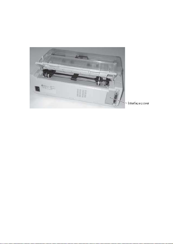
The interface connection for the optional interface is
located at the rear of the printer, on the left side (seen
from the printers front).
It is protected by a cover.
1 Use a screwdriver to remove the two screws of the
interface cover.
2 Remove the cover. You can now see the interface
socket and two guides (bottom, top) A.
Page 4

3 Take the interface module and make sure that the
two screw openings are pointing to the right. Slide
the interface module into the guides and push it
carefully into the printer until the connector of the
interface module is properly seated into the socket.
Fasten the interface module with the two screws to the
printer. The left example shows the RS232C interface,
the right example the Ethernet interface.
4 Connect the interface cable to the printer and the
computer.
Page 5

Ethernet interface
The Ethernet interface affords the printer to
connect to local area networks.
Its attributes are:
Hardware LAN/Ethernet: RJ45, Ethernet
Supported
operating
systems
Supported
protocols
Set-up Web browser (HTTP/HTML),
Management Web browser (HTTP/HTML),
Cable length 100 m max. (Cat 5e)
100BaseTX with 100 Mbps
(IEEE802.3u), 10Base-T with 10
Mbps (IEEE802.3) Speed:
10/100 Half/Full Duplex
Windows: Vista, Server 2003,
XP, 2000, NT, ME, 98, 95 Unix:
BSD, System V, HP-UX, AIX
Linux: SUSE, Red Hat
Printing: TCP/IP, LPR/LPD, Raw
Port 9100, FTP, IPP, NetBIOS,
AppleTalk (EtherTalk) Booting:
BOOTP, DHCP, RARP, Auto-IP
Configuration: HTTP, TCP/IP,
FTP, WINS, DNS Status: SNMP,
TCP/IP, PING, SMTP
PrintGuide™ (TCP/IP), ARP,
RARP, FTP, ASCII file download,
DHCP, BOOTP, WINS, DNS
PrintGuide™ (TCP/IP), HP
WebJetAdmin or other SNMP
management tool, E-mail
notification using SMTP, File
based using FTP
Page 6

For more information on Ethernet interface
specifications, refer to the User Guide on the Online
CD-ROM delivered with the Ethernet interface.
Page 7

IP address
The IP address, subnet mask and gateway address can be set
in the menu of the printer via the control panel.
Printer LEDs
The LEDs of the Ethernet signal different modes.
• Yellow only: The LED will blink once every second
until an IP address is assigned. The LE D blinks faster or
lights constantly, if there is an error. If this is the case,
check cables and restart the TallyCom III™.
• Green only: TallyCom III™ is receiving data from the
network.
• Yellow and Green: Lights up shortly at power on.
Blinks when resetting to factory default.
Reset the Ethernet interface
To clear all settings to factory default you must ensure that
TallyCom III™ is powered on and hold the TEST button down
until the LEDs blink (~ 8 seconds).
Printing test page
Ensure that the printer is powered on. Press the TEST button
down for about 1 second.
Printer starts to print the print server’s test
page.
Page 8

NOTE:
This equipment has been tested and found to comply with the limits
for a Class B digital device, pursuant to part 15 of the FCC Rules.
These limits are designed to provide reasonable protection against
harmful interference in a residential installation.
This equipment generates, uses and can radiate radio frequency
energy and, if not installed and used in accordance with the
instructions, may cause harmful interference to radio Communications.
However, there is no guarantee that interferenc e will not occur in a
particular installation. If this equipment does cause harmful
interference to radio or television reception, which can be dete rmined
by turning the equipment off and on, the user is e ncouraged to try to
correct the interference by one or more of the following measures:
- Reorient or relocate the receiv ing antenna.
- Increase the separation between the equipment and receiver.
- Connect the equipment into an outlet on a circuit different from that
to which the receiver is connected.
- Consult the dealer or an experienced radio/TV technician for help.
CAUTION:
Changes or modifications not expressly approved by Dascom could
void the user's authority to operate this equipment according to part
15 of the FCC rules.
CE conformance
This product has been developed and produced in accordance with the
EMC directive and the Low Voltage directive and therefore carries the
CE mark.
Company and product names mentioned in this guide are trademarks
or registered trademarks of their respective owners.
© October 2009 Dascom 396957a
 Loading...