


User Guide T5040 Flatbed Printer

TRADEMARK ACKNOWLEDGEMENTS
• Centronics is a trademark of Centronics Data Computer Corporation.
• PCL and PCL6 are trademarks of Hewlett-Packard Company.
• IBM and IBM PC are trademarks of International Business Machines Corporation.
• Apple, AppleTalk, TrueType, Laser Writer and Macintosh are trade-marks of Apple Computer, Inc.
• Microsoft, Windows, Windows 9x, Windows ME, Windows 2000, Windows NT, Windows XP and MSDOS are registered trademarks of Microsoft Corporation.
• PostScript is a trademark of Adobe Systems Inc.
• All other brand or product names are trademarks of their respective companies or organizations.

User Guide Table of contents
Table of contents
Introduction 1
Printer features 1
Interfaces 1
Emulations 1
Symbols used 1
About this manual 2
1
Printer at a glance 3
View from the front 3
View with cover opened 3
View from the rear 4
2
Installation 5
Unpacking the printer 5
Placing your printer 6
Checking the printer voltage 8
Connecting the printer 8
Switching on the printer 10
3
Printer drivers and firmware 11
Printer drivers 11
Installing a printer driver in Windows 95/98/ME 11
Installing a printer driver in Windows 2000/
2003/XP 11
Installing a printer driver in Windows 7 13
Installing a printer driver in Windows Vista 14
Other operating systems 15
Changing printer settings 15
Form settings (Windows 2000/2003/XP/Vista/
Windows 7/2008) 16
Loading firmware 17
I

Table of contents User Guide
Interface 17
Serial interface 17
Parallel interface 18
USB interface (Windows2000/XP) 18
Downloading firmware to the printer 18
4
Control panel 19
Display, indicators and keys 20
Status indicators 21
Status indicator variations 21
Ready indicator (STOP LED) 22
Paper indicator (PAPER LED) 23
USER1 and USER2 indicators 24
Key functions during operation 25
STOP/EJECT key 25
USER1 and USER2 key 26
Key functions when powering on 27
STOP/EJECT key 27
USER2 key 27
USER1 key 28
Key functions in menu mode 29
USER1 key 29
USER2 key 29
STOP/EJECT key 29
5
Print media 31
Inserting a document 31
Inserting a passbook 32
Removing media 34
6
Changing the ribbon cassette 35
Removing the ribbon cassette 35
Inserting the ribbon cassette 37
7
Replacing the print head 41
Removing the print head 41
Inserting new print head 44
II

User Guide Table of contents
8
Menu 47
Programming using the control panel 47
Calling up the menu 48
Menu configurations (USER1/USER2) 48
Menu handling 49
Key functions 49
USER1 key 49
USER2 key 49
STOP/EJECT key 50
Setting parameters (principle) 51
Terminating menu mode 52
Selecting the LC display language 53
Printing out the status page 55
Power on + USER2 key 55
Print out status page in menu mode 56
Status page (example) 58
Menu parameters 59
Test function 65
Hex Dump 65
Activating Hex Dump 65
Exiting the test mode 66
Test printout Hex Dump (Example) 66
9
Troubleshooting 67
General print problems 68
The display remains dark 68
The display is lit, but the printer does
not print 68
Problems with paper feed 69
Problems with the print quality 70
Print is faulty 70
Print is too pale 70
Smudged print 70
Dots within characters are missing 70
Prints undefined characters 70
Error messages and warnings 71
Unrecoverable errors 72
Recoverable errors 73
III

Table of contents User Guide
Print Head Hot Error 73
Ribbon Cassette Error 73
Paper Length Error 73
Framing Error (Serial I/F) 74
Parity Error (Serial I/F) 74
Overrun Error (Serial I/F) 74
Cover Open Error 74
Cover Open Error 74
Warnings 75
Data in Buffer 75
Remove Paper 75
Clearing paper jams 76
10
Care and maintenance 79
Cleaning the housing 79
Cleaning the interior 79
Cleaning the MSR-H magnetic stripe 80
Transport of the printer 82
Preparations for transport 82
Shipping the printer 82
A
Specifications 83
Printer specifications 83
Paper specifications 87
Interface specifications 89
B
Character sets 91
OCR-A character set 92
Epson character sets 93
Italic 93
Graphic1 93
Graphic2 94
IV
IBM code pages 95
Code page 437 95
Code page 850 95
Code page 860 96
Code page 863 96

User Guide Table of contents
Code page 865 97
Code page 851 97
Code page 852 98
Code page 853 98
Code page 855 99
Code page 857 99
Code page 866 100
Code page 869 100
Code page USSR Gost 101
Code page 864 101
Code page 437G 102
Code page 920 (equivalent to ISO 8859-9) 102
Code page 858 103
Code page 923 (equivalent to ISO 8859-15) 103
ISO code pages 104
ISO 8859-2 104
ISO 8859-5 104
ISO 8859-7 105
ISO 8859-8 105
Available code pages and fonts 106
C
Emulations 109
Escape sequences 109
What are escape sequences? 110
Control codes 110
How are escape sequences used? 110
List of available control codes 111
PR2 mode 111
PR50 mode 114
PR2845 mode 117
IBM mode 120
Epson mode 123
D
Interfaces 127
Interface settings for User 1 and USER2 127
Parallel interface 128
Connector assignment 128
Nibble Mode 128
ECP mode 129
V

Table of contents User Guide
Serial interface RS232C 130
Connector assignment 130
Serial attachment characteristics 131
Data rates 131
Supported protocols 131
Data Transfer 131
Parity 131
Handshake 132
Ready/Busy (Hardware Handshake) 132
XON/XOFF (Software Handshake) 132
Configuring the serial interface of the PC 133
DOS mode/Command line 133
Windows 95/98 133
Windows 2000/XP 133
USB interface 134
E
Consumables and accessories 135
Consumables 135
Accessories 135
VI

User Guide Introduction
Introduction
Printer features This printer is a document printer for printing manually inserted docu-
ments as well as passbooks (vertical and horizontal fold passbooks).
Manual insertion of the documents is supported by an automatic document alignment function.
The printer has a high processing speed and compact design. The
24-needle print head guarantees excellent print quality.
Different factory installed models can be delivered: MSR (magnetic
stripe read/writer), scanner and second serial interface.
Interfaces The basic printer model is provided with three interfaces: serial
(RS-232C), parallel (IEEE1284) and USB 2.0 (Full speed). A special
printer version has a second serial (RS-232C) interface.
Emulations As standard, the printer is delivered with three emulations: EPSON
ESC/P, IBM 4722 + PP XL24e, Olivetti PR2e, PR50 and PR2845.
Symbols used Important information is highlighted in this manual by two symbols.
STOP
CAUTION highlights information which must be observed in order to
prevent injuries to the user and damage to the printer.
NOTE highlights general or additional information about a specific topic.
1

Introduction User Guide
About this manual This user guide contains a detailed description of the printer, its
characteristic features and additional information.
` Chapter 1 Printer at a glance lists all the parts of the printer.
` Chapter 2 Installation contains start-up instructions and points to no-
te.
` Chapter 3 Printer drivers and firmware provides instructions for in-
stalling the printer driver.
` Chapter 4 Control panel explains how to control printer operations.
` Chapter 5 Print media tells you how to load, transport and eject
media.
` Chapter 6 Changing the ribbon cassette explains how to remove and
install a ribbon cassette.
` Chapter 7 Replacing the print head explains how to remove and
install a print head.
` Chapter 8 Menu contains all the information necessary for con-
trolling the printer via the control panel.
` Chapter 9 Troubleshooting provides instructions for rectifying faults
which do not require the intervention of qualified personnel.
` Chapter 10 Care and maintenance provides information on the up-
keep of the printer and contains important information in case the
printer has to be transported.
` Appendix A Specifications informs you about the technical specifi-
cations of your printer and the paper which should be used.
` Appendix B Character sets lists the available character sets.
` Appendix C Emulations deals with programming via the interface.
` Appendix D Interfaces explains the interfaces.
` Appendix E Consumables and accessories contains information
about consumables and accessories which can be purchased for
your printer.
2
User Guide Printer at a glance
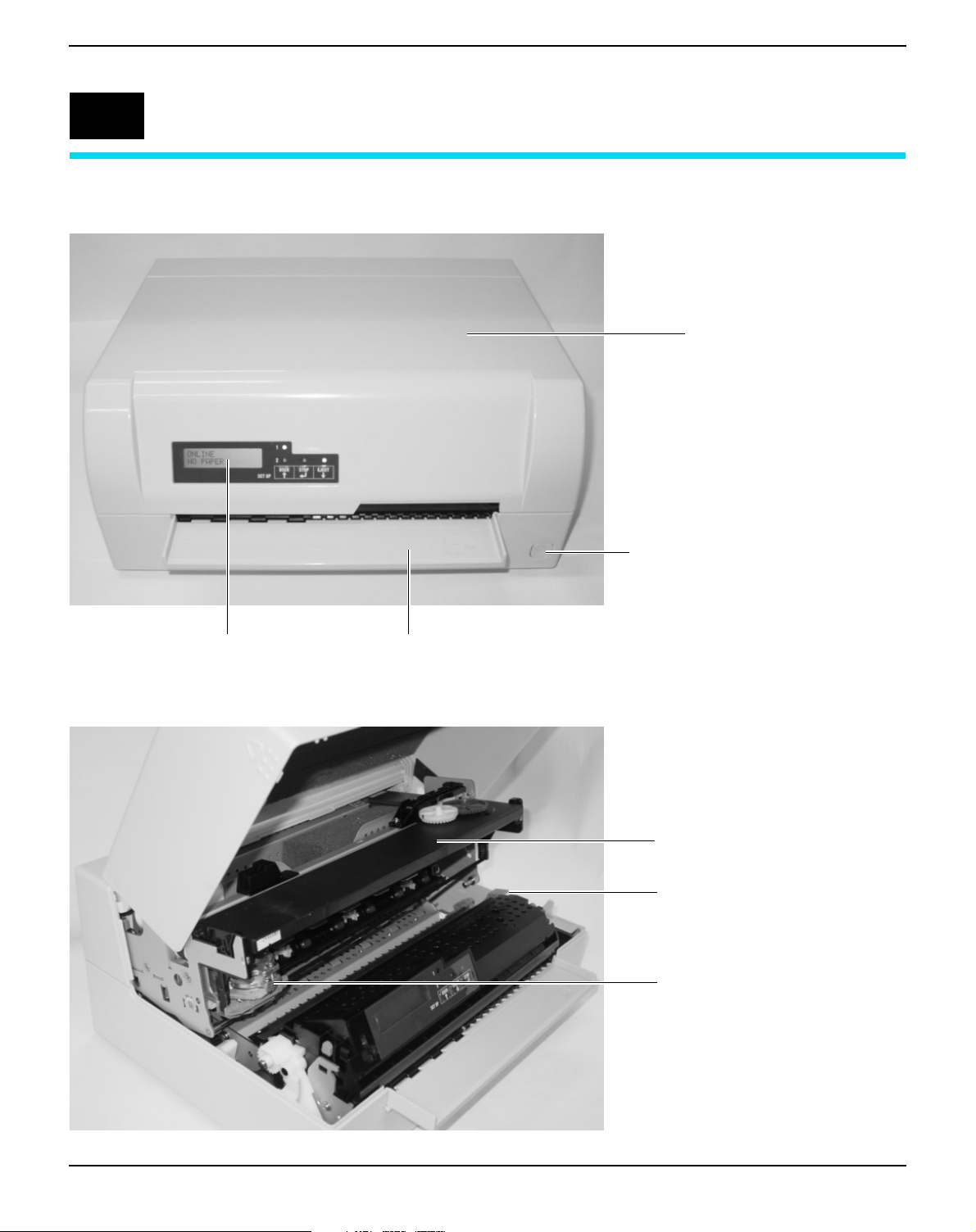
1
Printer at a glance
View from the front
Cover
Power switch (On/Off)
Control panel Paper tray
View with cover opened
Ribbon cassette
Release lever
Print head
3
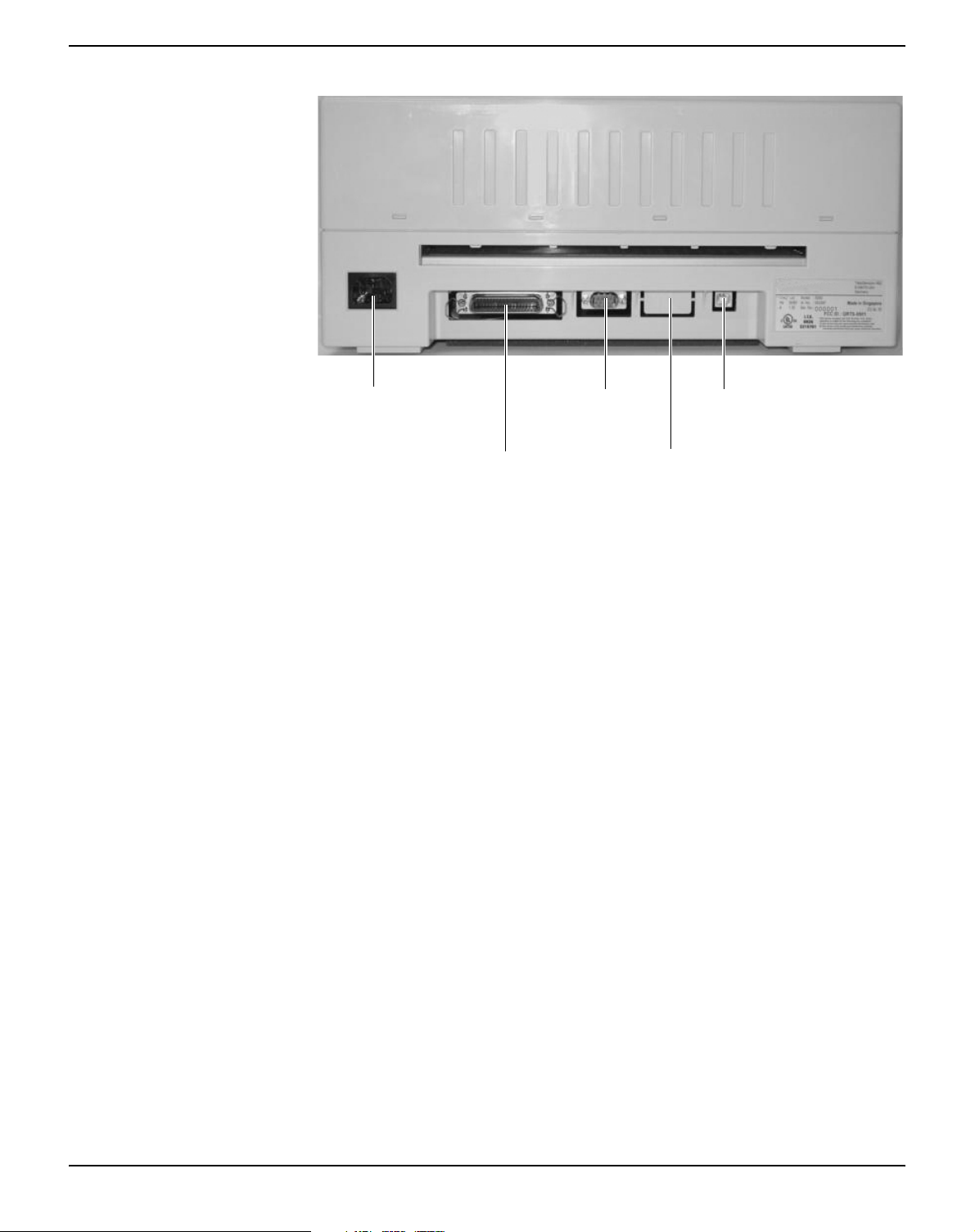
Printer at a glance User Guide
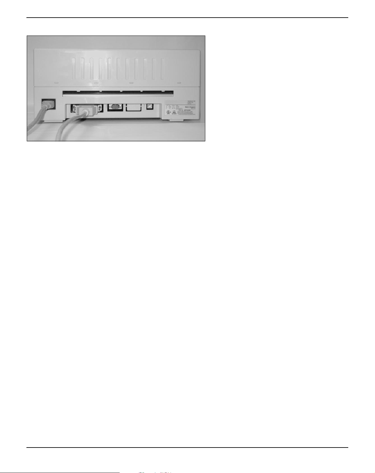
View from the rear
Power
inlet
Parallel
interface
1st Serial
interface
2nd Serial
interface
(special version)
USB
interface
4

User Guide Installation
2
Installation
Unpacking the printer Place your packaged printer on a solid base.
Make sure that the “Up” symbols is pointing up.
Open the packaging, lift the printer out of the cardboard box and remove the remaining packaging material.
Check the printer for any visible transport damage and missing items.
The following items should be enclosed:
` The Quick start guide (QSG)
` This CD-ROM (at the back of the Quick start guide)
` The power cable
` The ribbon cartridge
If you find any transport damage or if any accessories are missing, please contact your dealer.
5
Installation User Guide
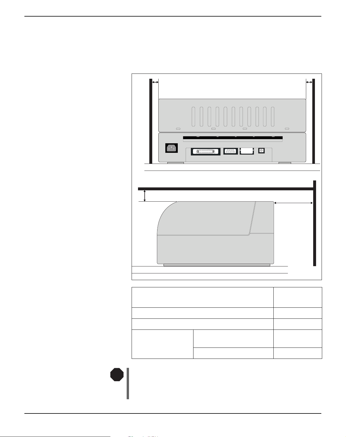
Placing your printer Place the printer on a solid, flat, surface, ensuring that the printer is po-
sitioned in such a way that it can not topple, and that there is easy access
to the control panel and paper input tray. Also ensure there is sufficient
space for the printed output.
min. 1 cm min. 1 cm
min. 2 cm
min. 10 cm
Location
Left and right side of the printer 1 cm
Top of the printer 2 cm
Rear of the printer to ensure sufficient
ventilation
to print on a DIN A4 sheet 12 cm
Minimum
space
10 cm
STOP
The power supply cable may be damaged if the paper edges constantly chafe the insulating sheath. The user must always ensure
that there is sufficient distance between the power supply cable
and the paper.
6

User Guide Installation
When selecting the printer location, observe the following additional
instructions:
STOP
Never place the printer in the vicinity of inflammable gas or
explosive substances.
` Protect the printer from shock, impact and vibration.
` Be sure to connect the printer to a socket with the correct mains
voltage.
` Do not expose the printer to direct sunlight. If you cannot avoid pla-
cing the printer near a window, protect it from the sunlight with a
curtain.
` When connecting the computer with the printer, make sure not to
exceed the permitted cable length (see
Interface specifications,
page 89).
` Ensure sufficient distance between the printer and any heating
radiators.
` Avoid exposing the printer to extreme temperature or air humidity
fluctuations. Take care to avoid the influence of dust.
` Always disconnect the system from the mains before opening the
device to perform maintenance work or remedy errors.
7
Installation User Guide
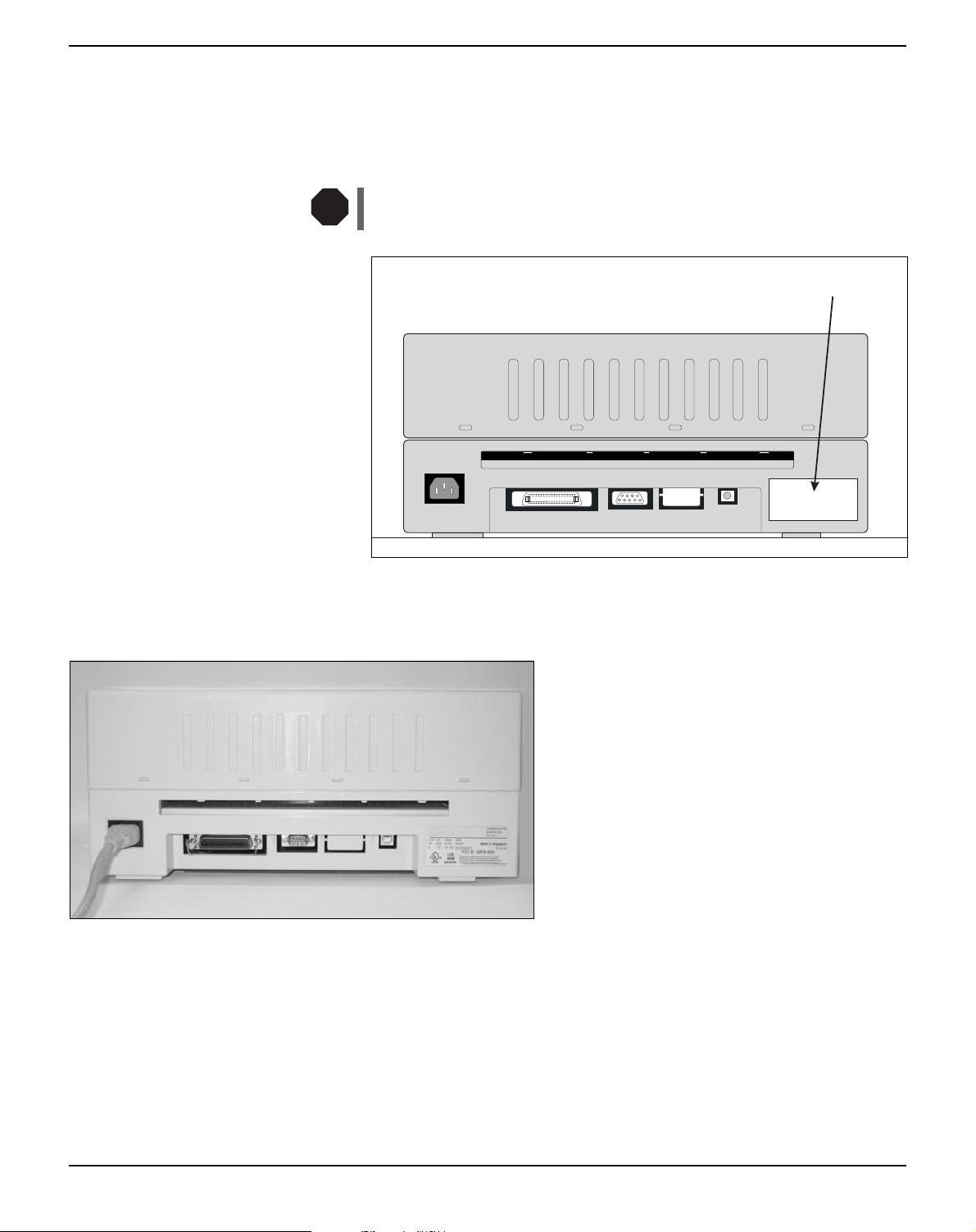
Checking the printer voltage
STOP
Make sure that the device has been set to the correct voltage (e.g. 230 V
in Europe, 120 V in the USA). To do this, check the type plate at the
back of the printer. Contact your dealer if the setting is incorrect.
Never switch on the printer if the voltage setting is incorrect,
since this may result in severe damage to the printer.
Type plate
Connecting the printer
Connect the power cable to the power inlet of
the printer. Connect the power cable plug to a
mains socket.
8
User Guide Installation
Make sure that the printer and the computer
are switched off and connect the data cable
between the printer and the computer. This
example shows a 36-pin centronics parallel
cable.
9
Installation User Guide
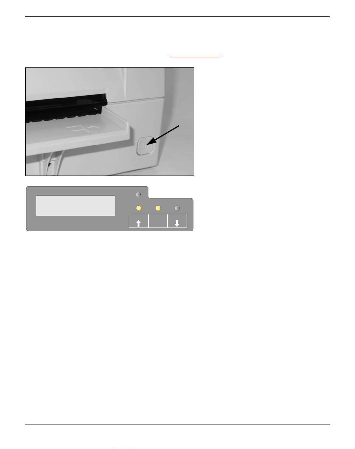
Switching on the printer
ONLINE
NO PAPER
P APER
SETUP
Before switching the printer on, make sure that it is connected correctly
and that you have followed all the safety and installation instructions
(see section Placing your printer, page 6).
Press the power switch which is located at the
front bottom right of the printer to switch on
the printer.
The printer initializes.
When initialization is completed, the Ready indicator and the USER1 indicator light up. The
message ONLINE NO PAPER appears on
USER1
STOP
/EJECT
USER2
the LCD. The printer is in the online status
and ready to accept data from the system. You
can now insert a document or passbook.
10
User Guide Printer drivers and firmware
3
Printer drivers and firmware
Printer drivers You must install a printer driver so that the printer can process the data
from your application programs.
An original driver offers the best conditions for optimal printing results. All available Windows printer drivers can be found on the CD-ROM
en-closed with the printer, and also from our Internet site, from which
you can download updated versions as required.
The use of any Windows printer driver from the CD-ROM requires
that the printer is set to Epson emulation (see Menu parameters,
page 59 and chapter Emulations, page 109).
Installing a printer driver in Windows 95/98/ME
In this operating system the compatible 5040 driver can be used.
Installing a printer driver in Windows 2000/2003/XP
The online CD-ROM contains printer drivers for the most common
Windows applications. To install the printer driver, proceed as follows.
1.
Insert the supplied online CD-ROM in the CD-ROM drive.
2.
Click on the Start button in the Windows taskbar.
3.
Click on Printers and Faxes to open the printer folder.
4.
Click on File and Add Printer in the menu bar.
5.
Click on Next In the Printer Installation Wizard.
6.
Specify whether you want to operate the printer as a Local Printer
or Network Printer by clicking on the relevant option, then press
Next.
For instructions on installing the printer as a network printer,
please consult the documentation supplied with your network
operating system and/or printer server, or contact the network
administrator.
To install a network printer, you will need Administrator rights.
If you are using the printer locally, you can continue installing the driver
11

Printer drivers and firmware User Guide
in one of two possible ways:
` Manual installation of printer driver: in this case, continue with
Step 7.
` Automatic installation of printer driver via Plug & Play function: in
this case, continue with Step 12 once the printer installation wizard
has determined the printer, port and printer name.
Then click on Next.
7.
Select the port to which your printer is connected, then click on
Next.
8.
Click on Data Carrier, then click on Browse.
9.
Select the CD-ROM drive and open the directory n:\driver (“n“
stands for the letter of your PC drive).
10.
Open the folder 32Bit or 64Bit.
11.
Select the printer type and then click on Next.
12.
If required, edit the name of the default printer and specify whether you wish to use the printer as a default printer by clicking on
the relevant option. Then click on Next.
13.
If you are using the printer as a network printer, you have the
option of sharing it with other network users. In this case you must
enter an access name which will be displayed to the other network
users.
Then click on Next.
14.
Specify whether you wish to print out a test page (recommended)
by selecting the relevant option and click on Finish. The printer
driver will now be installed.
12

User Guide Printer drivers and firmware
Installing a printer driver in Windows 7
The online CD-ROM contains printer drivers for the most common
Windows applications. To install the printer driver, proceed as follows.
1.
Insert the supplied online CD-ROM in the CD-ROM drive.
2.
Click on the Start button in the Windows taskbar.
3.
Click on Devices and Printers to open the printer folder.
4.
Click on Add a Printer in the menu bar.
5.
Specify whether you want to operate the printer as a Local Printer
or Network, wireless or Bluetooth printer by clicking on the
relevant option, then press Next.
For instructions on installing the printer as a network printer,
please consult the documentation supplied with your network
operating system and/or printer server, or contact the network
administrator.
To install a network printer, you will need Administrator rights.
If you are using the printer locally, you can continue installing the driver
in one of two possible ways:
` Manual installation of printer driver: in this case, continue with
Step 6.
` Automatic installation of printer driver via Plug & Play function: in
this case, continue with Step 11 once the printer installation wizard
has determined the printer, port and printer name.
6.
Select the port to which your printer is connected, then click on
Next.
7.
Click on Have Disk, then click on Browse.
8.
Select the CD-ROM drive and open the directory n:\driver (“n“
stands for the letter of your PC drive).
9.
Open the folder 32Bit or 64Bit.
10.
Select the printer type and then click on Next.
11.
If you are using the printer as a network printer, you have the
option of sharing it with other network users. In this case you must
enter an access name which will be displayed to the other network
users.
Then click on Next.
12.
If required, edit the name of the default printer and specify whether you wish to use the printer as a default printer by clicking on
13

Printer drivers and firmware User Guide
the relevant option. Then click on Next.
13.
Specify whether you wish to print out a test page (recommended)
by selecting the relevant option and click on Finish. The printer
driver will now be installed.
Installing a printer driver in Windows Vista
The online CD-ROM contains printer drivers for the most common
Windows applications. To install the printer driver, proceed as follows.
1.
Insert the supplied online CD-ROM in the CD-ROM drive.
2.
Click on the Start button in the Windows taskbar.
3.
Click on All Programs.
4.
Click on Devices and Printers to open the printer folder.
5.
Click on Printers in the menu window.
6.
Click on Add a Printer in the menu bar.
7.
Specify whether you want to operate the printer as a Local Printer
or Network, wireless or Bluetooth printer by clicking on the
relevant option, then press Next.
For instructions on installing the printer as a network printer,
please consult the documentation supplied with your network
operating system and/or printer server, or contact the network
administrator.
To install a network printer, you will need Administrator rights.
If you are using the printer locally, you can continue installing the driver
in one of two possible ways:
` Manual installation of printer driver: in this case, continue with
Step 8.
` Automatic installation of printer driver via Plug & Play function: in
this case, continue with Step 13 once the printer installation wizard
has determined the printer, port and printer name.
8.
Select the port to which your printer is connected, then click on
Next.
9.
Click on Have Disk, then click on Browse.
14
10.
Select the CD-ROM drive and open the directory n:\driver (“n“
stands for the letter of your PC drive).
11.
Open the folder 32Bit or 64Bit.
12.
Select the printer type and then click on Next.

User Guide Printer drivers and firmware
13.
If you are using the printer as a network printer, you have the
option of sharing it with other network users. In this case you must
enter an access name which will be displayed to the other network
users.
Then click on Next.
14.
If required, edit the name of the default printer and specify whether you wish to use the printer as a default printer by clicking on
the relevant option. Then click on Next.
15.
Specify whether you wish to print out a test page (recommended)
by selecting the relevant option and click on Finish. The printer
driver will now be installed.
Other operating systems The printer can also be used with other operating systems such as Linux
or Unix. In this case, set the printer to the EPSON or IBM Proprinter
emulation for which default drivers are available in most operating
systems.
Changing printer settings You can make permanent changes to the printer settings using the con-
trol panel of the printer (see chapter Menu, page 47). Various printer
settings can also be entered in the operating system of your PC,
however.
1.
Click on the Start button in the Windows taskbar.
2.
Windows 95/98: move the mouse to Settings and click on Printers
to open the printer folder.
Windows 2000/XP: click on Printers and Faxes to open the prin-
ter folder.
3.
Move the mouse pointer to the appropriate printer symbol, press
the right mouse key and click on Properties.
Details of the settings available in this window can be found in the Windows documentation or help pages.
Settings entered in the printer driver via Windows have priority
over settings entered via the printer menu.
15
Printer drivers and firmware User Guide
Form settings (Windows 2000/2003/XP/ Vista/Windows 7/2008)
In contrast to Windows versions 95/98, in which forms are defined in
the printer driver itself, Windows versions 2000/2003/XP/Vista/Windows 7/2008 have a central facility for managing form properties and
assign one paper feed only.
If you want to set up a form not included in the Windows default settings, proceed as follows.
You will need Administrator rights to define new forms.
1.
Click on the Start button in the Windows taskbar.
2.
Click on Printers and Faxes to open the printer folder.
3.
In the menu bar, click on File and Server Properties.
4.
In the window Printer Server Properties, click on Form if necessary.
5.
Either select an existing form from the Forms list or activate the
option New Form.
6.
Enter a form name and the desired values.
7.
Click on Save to save the new form.
You can now assign this form to the paper feeds of your printer (see
Changing printer settings, page 15).
The form cannot be assigned if its dimensions exceed the permissible paper sizes of the specified paper feed.
16

User Guide Printer drivers and firmware
Loading firmware The most current version of the firmware can be downloaded from our
Internet site. There you will find also additional informations regarding
the firmware and printer upgrades. Make sure that the download consists of the following files:
` Standard Model PB Flash VX.XX.exe: the memory writer (flash)
` BL_XXXX.IPL: Bootblock of the printer
` FWXXXX.mfw: Main firmware of the printer
` PBCGXXXX.BIN: Character generator (EU/US)
You can select the standard character generator (CG) or four
optional character generators. Every optional CG provides the
standard fonts and one additional font:
Standard CG Optional CG 1 Optional CG 2 Optional CG 3 Optional CG 4
PBCGSTD.BIN
DraftDraftDraftDraftDraft
Draft Banking
Roman Roman Roman Roman Roman
Courier Courier Courier Courier Courier
Sans Serif Sans Serif Sans Serif Sans Serif Sans Serif
Gothic Gothic Gothic Gothic Gothic
OCR-A OCR-A OCR-A OCR-A OCR-A
OCR-B OCR-B OCR-B OCR-B OCR-B
– Prestige Elite Script Orator Bold
PBCGPE.BIN PBCGSC.BIN PBCGOR.BIN PBCGBO.BIN
Draft Banking
Draft Banking
Draft Banking
Draft Banking
Interface You can use the serial, the parallel or the USB interface to download
the firmware to the printer.
Make sure that the selected interface is not connected to another
printer.
Serial interface Make sure that the serial interface is selected in the printers menu for
USER1 and that the settings for Baudrate and Protocol on printer and
PC are identical.
17

Printer drivers and firmware User Guide
Parallel interface Make sure that the parallel interface is selected in the printers menu for
USER1, that in the PCs BIOS the parallel port is set to ECP and that
the parallel cable meets the IEEE1284 standard.
USB interface (Windows2000/ XP)
Downloading firmware to the printer
Make sure that the USB interface is selected in the printers menu for
USER1, that a printer driver has been installed and the printer is defined as default printer.
To load new firmware to the printer, proceed as follows. As mentioned
before it is important that no other device (printer) is set to the interface you want to use for the download.
Click therefore Start > Control Panel > Printers and Faxes and
check that no printer is set to the port you want to use. E.g. if you want
to use the serial interface RS232 no printer may have connected to the
COM1 port.
1.
Browse to the folder where the firmware files are stored.
2.
Double-click the Standard Model PB Flash VX.XX.exe file.
3.
On the Memory Writer screen select the interface (in our example
serial port).
4.
Make sure that the settings for port, baudrate, parity bit and stop
bit are correct.
5.
Select IPL FIRMWARE from Download Type.
6.
Click Browse and select the BL_XXXX.IPL file.
7.
Click FLASH NOW; the download process starts.
When the download process is finished, the printer performs an initialization
8.
Repeat step 5 to 7 for the FWXXX.mfw file and the
PBCGXXXX.BIN file.
18

User Guide Control panel
4
Control panel
The control panel allows the user to set some functions in the printer
and set up the basic printer parameters on installation. The control panel is located on the front right side of your printer and consists of a
two-line LC display with 2 x 16 digits, three keys for controlling the
printer functions and four LED indicators displaying the status of the
printer.
The functions of the keys depend on the printer’s current mode (status). There are three basic modes.
` The Online mode is the printer’s normal operating mode. Data from
your computer can be received and printed.
` In the Offline (STOP) mode the link between printer and computer
is interrupted, i.e. no data can be received and printed.
` In the Menu mode printer settings (line spacing, size of the inter-
face buffer etc.) can be changed and saved permanently.
19
Control panel User Guide
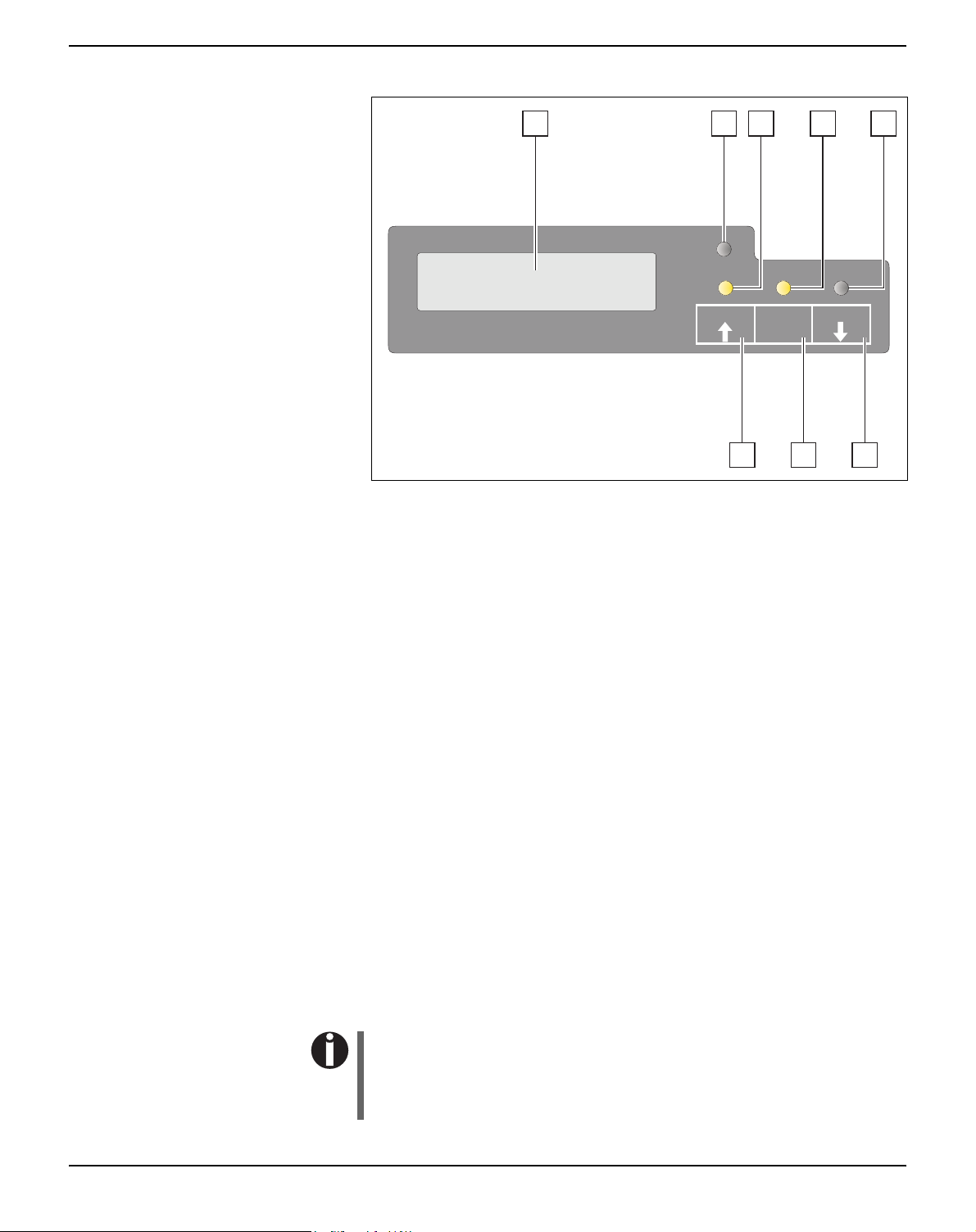
Display, indicators and keys
1 2 3 4 5
P APER
ONLINE
NO PAPER
USER2
678
SETUP
USER1
STOP
/EJECT
1
LCD display: Displays the internal printer status, operating
instructions and error messages.
2
Paper LED: Indicates whether paper is loaded; on = paper is
inserted, off = no paper inserted; blinking = indicates that data has
been sent to the printer.
3
USER1 LED: Blinks if the printer is receiving data via the first
interface, lights if a job is printed (see below).
4
Ready LED: Indicates Offline or Online status; on = online,
off = offline; blinking = indicates that an error has occured, the
cause of the error is indicated in the display.
5
USER2 LED: Blinks if the printer is receiving data via the second
interface, lights if a job is printed (see below).
6
USER2 key: Activated by application only; the functionality of the
key depends on the emulation and the application used (see also
USER2 LED).
7
STOP/EJECT key: Sets the printer to Online/Offline mode (see
also Ready LED); ejects inserted paper (see also Paper LED).
8
USER1 key: Activated by application only; the functionality of the
key depends on the emulation and the application used (see also
USER1 LED).
20
Please be aware that some emulations and applications may use
the LEDs and keys in an entirely different way defined by the
emulation and/or host software and outside the definitions contained in this document.
User Guide Control panel
Status indicators
Status indicator variations
This section defines the status of the control panel. The LED lights
will be on, off or blinking coupled with messages from the LCD. In this
way the printer reports its current status.
Read
Paper
y
off off — — STOP
off off on — LOAD
off off — on LOAD
USER1USER
2
LCD Indicated Printer Status
Offline, no paper loaded
NO
PAPER
Offline, printer waiting for
PAPER
PAPER
paper as it has received
data from the host
(if data + Print Start com-
mand are transferred from
Host)*
Offline, printer waiting for
paper as it has received
data from the host
(If data + Print Start com-
mand are transferred
from Host)*
on off on — LOAD
PAPER
on off — on LOAD
PAPER
on on — — ONLINE
PAPER
on off — — ONLINE
NO
PAPER
blink blink — — xxxxx
xxxxx
— — on off Printer is under USER1 con-
— — off on Printer is under USER2 con-
* applies to EPSON/IBM emulation only
Online, paper required
(If data + Print Start com-
mand are transferred from
Host)*
Online, paper required
(If data + Print Start com-
mand are transferred
from Host)*
Online, paper is loaded
Online, no paper is loaded
Error. The cause of the
error is displayed on the
LCD
trol
trol
21
Control panel User Guide
Ready indicator (STOP LED)
Ready indicator (STOP LED) not lit:
P APER
` The printer is in the stop status (Offline) and will not receive data
from the system.
SETUP
P APER
SETUP
P APER
SETUP
USER1
USER1
USER1
STOP
/EJECT
STOP
/EJECT
STOP
/EJECT
USER2
Ready indicator (STOP LED) lit:
` The printer is switched on in the online status. It is ready to receive
data from the system.
USER2
Ready (STOP LED) and Paper indicators (PAPER LED) blink:
` The printer is not ready. A device error has occurred. Any data
transferred from the system is deleted. The cause of the error is indicated on the LCD.
USER2
22

User Guide Control panel
Paper indicator (PAPER LED)
Paper indicator (PAPER LED) does not light:
P APER
` No paper is inserted in the printer.
SETUP
P APER
SETUP
P APER
SETUP
P APER
SETUP
USER1
USER1
USER1
USER1
STOP
/EJECT
STOP
/EJECT
STOP
/EJECT
STOP
/EJECT
USER2
Paper indicator (PAPER LED) lights:
` Paper is inserted in the printer.
USER2
Paper indicator (PAPER LED) blinks:
` Paper required: The system has transferred data to the printer but
there is no document or passbook inserted into the document
support.
USER2
Ready (STOP LED) and Paper (EJECT LED) indicators blink:
` The printer is not ready. A device error has occurred. Any data
transferred from the system is deleted. The cause of the error is indicated on the LCD. If paper is loaded, it will be ejected.
USER2
23

Control panel User Guide
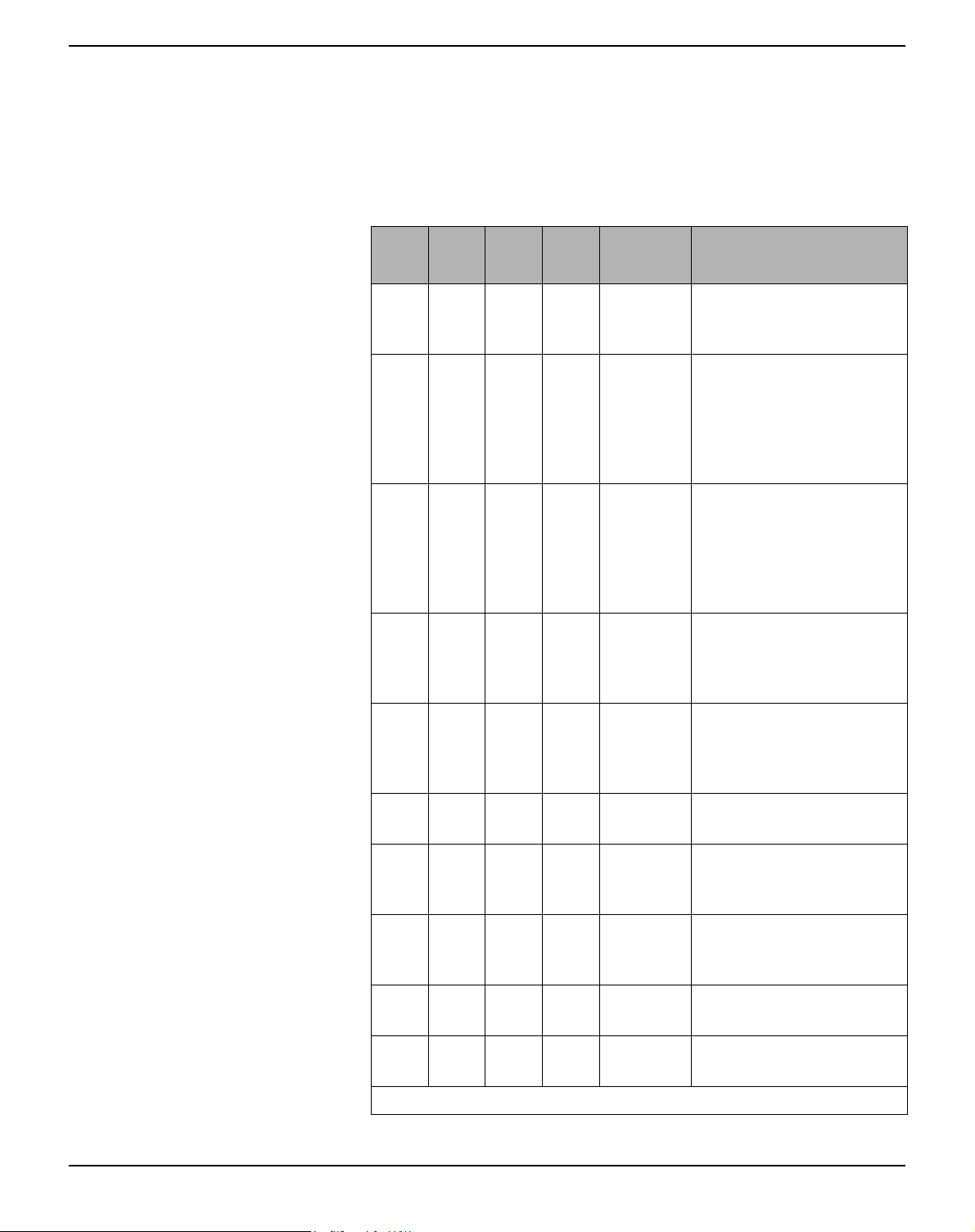
USER1 and USER2 indicators The USER1 and USER2 LEDs are normally under the control of the
application. They are available to indicate to the user that the appropriate interface is active. Normally in Olivetti, IBM or Epson (Auto)emulations, with dual host connections they will indicate that a job
is available for the interface associated with the USER. In Epson Emulation (Manual mode) they are lit under the control of the printer to indicate the availability of a job for process: the job can be released by
inserting paper and pressing the associated key.
However please be aware that some applications may uses the LEDs
and keys in an entirely different way defined by the host software and
outside the definitions contained in this document.
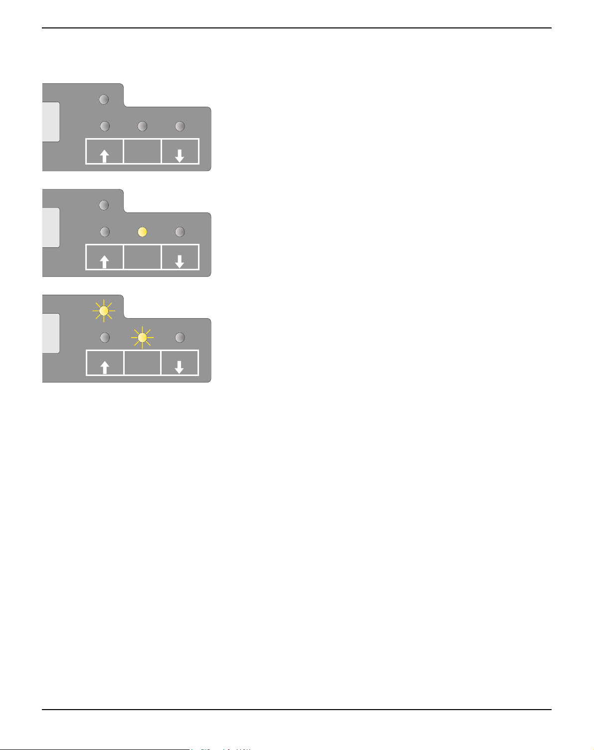
The USER1 or USER2 indicator blinks:
P APER
` USER1 (interface 1) or USER2 (interface 2) receives data.
SETUP
P APER
SETUP
USER1
USER1
STOP
/EJECT
STOP
/EJECT
USER2
The USER1 or USER2 indicator lights:
` USER1 (interface 1) or USER2 (interface 2) processes data.
USER2
24

User Guide Control panel
Key functions during operation
STOP/EJECT key
With the Ready indicator lit, the printer is rea-
ONLINE
NO PAPER
STOP
NO PAPER
P APER
SETUP
P APER
SETUP
USER1
USER1
STOP
/EJECT
STOP
/EJECT
USER2
USER2
dy to recieve data from the host. You can
switch the printer from online to offline by
pressing the STOP/EJECT key.
When the Ready indicator is not lit, the printer
is Offline and will not receive data. Press the
STOP/EJECT key to switch the printer Online. Alternatively if paper is still in the printer
when in the Off-lLine condition, the paper
will be ejected.
ONLINE
PAPER
DATA
NO PAPER
XXXXX
XXXXX
P APER
SETUP
P APER
SETUP
P APER
SETUP
USER1
USER1
USER1
STOP
/EJECT
STOP
/EJECT
STOP
/EJECT
USER2
USER2
USER2
If paper is loaded when the printer is online
(Ready and Paper indicator lit), by pressing the
STOP/EJECT key, the document will be
ejected, the LCD displays REMOVE
PAPER. The printer remains online.
When the printer is online and the Paper indicator is off and there is data in the printer buffer, the LCD displays DATA/NO PAPER.
You can switch the printer from online to offline by pressing the STOP/EJECT key.
When the Ready and Paper indicators blink,
an error has occured. Annotate the displayed
message in the LCD display. By pressing the
STOP/EJECT key, paper will be ejected if
loaded.
If the error message doesn’t disappear after
pressing STOP/EJECT key, power the printer off and on again. If the error consists, contact your customer support.
25

Control panel User Guide
USER1 and USER2 key
The USER1 and USER2 keys are by default
ONLINE
PAPER
P APER
SETUP
USER1
STOP
/EJECT
USER2
inactive. They must be activated via an application. The functionality of the keys then depend on the selected emulation and the
sequences sent to the printer.
For more information on emulations and sequences please refer
to the programmer’s application manual.
26

User Guide Control panel
Key functions when powering on
STOP/EJECT key
Powering on the printer whilst holding the
STOP/EJECT key will activate “Hex
Dump” mode. Keep the STOP pressed until
PAPER
SETUP
USER1
STOP
/EJECT
USER2
the message Hex Dump NO PAPER appears on the LCD display.
Refer to the section Hex Dump, page 65, for a
description of how to activate/deactivate and
perform the test printout.
USER2 key
PAPER
USER1
STOP
SETUP
/EJECT
USER2
Powering on the printer whilst holding the
USER2 key, and subsequently loading paper
on instructions from the LCD panel will allow
you to make a status print. This is a print of all
the parameter settings. Keep the USER2 key
pressed until the message Print StatusPage
Load Paper appears on the LCD display.
Refer to the section
status page, page 55, for further details on the
Printing out the
status page.
27

Control panel User Guide
USER1 key
Powering on the printer whilst holding the
USER1 key will allow you to enter menu mode. Keep the USER key pressed until the mes-
PAPER
SETUP
USER1
STOP
/EJECT
USER2
sage MENU USER appears on the LCD
display.
Refer to the section Menu parameters, page 59,
for further details on the menu mode.
28

User Guide Control panel
Key functions in menu mode
USER1 key
MENU
COMMON
USER2 key
MENU
COMMON
P APER
SETUP
P APER
SETUP
In menu mode the control panel keys have the following functions
The USER1 key is used to go to the next parameter group or next parameter on the same
menu level (symbolized by an arrow pointing
USER1
STOP
/EJECT
USER2
upwards).
It is also used to change parameter settings.
For further details refer to the section Menu
handling, page 49.
The USER2 key is used to go to the next parameter group or next parameter on the same
menu level (symbolized by an arrow pointing
USER1
STOP
/EJECT
USER2
downwards).
It is also used to change parameter settings.
For further details refer to the section
handling, page 49.
Menu
STOP/EJECT key In menu mode the STOP/EJECT key has the following functions:
The STOP/EJECT key is used to select the
next menu level (e.g. MENU USER > De-
fault Set User 1), to open a parameter item
for changing and to confirm changed parameter items.
For further details refer to the section
handling, page 49.
Menu
MENU
COMMON
P APER
SETUP
P APER
USER1
STOP
/EJECT
USER2
Default Set
Menu1 *
SETUP
USER1
/EJECT
STOP
USER2
29


User Guide Print media
5
Print media
Inserting a document Before inserting a document make sure that the printer is switched on
and the the message ONLINE NO PAPER is displayed in the LCD
(see Switching on the printer, page 10).
Insert the document in such a way that the
right paper edge is positioned inside the area
between the left side of the symbol and the
right edge of the document support, so that
the document alignment can grasp it securely.
This is especially important for documents
that are narrower than a A4 sheet.
Place right edge of
document inside
this area
Then push the document towards the stop
into the document chute.
When the document is drawn in, the message
ONLINE PAPER appears in the LCD.
When printing is completed, the document is
transported out of the printer and released for
removal. The message ONLINE NO PA-
PER appears on the LCD again.
31

Print media User Guide
Inserting a passbook Before processing a new vertical-fold or horizontal-fold passbook, you
should eliminate the stiffness of the fold by proceeding as follows.
Open the passbook on the page that you want
to print. Bend the fold backwards extremely
hard.
Stroke along the fold of the passbook with
both thumbs and index fingers and slightly
bend the passbook outwards. To print a new
passbook, repeat this procedure several times.
STOP
If the passbook has a magnetic
stripe, take care not to crease or
damage it in any way.
32

User Guide Print media
The bulge of the opened passbook should be
as flat as possible to ensure trouble-free transportation into the paper.
Place the passbook on the right-hand side of
the document support with the page to be
printed facing up. The passbook must be entered into the opening of the chute. Once in
the chute the printer mechanism will take the
book. At this point you may release the book,
as the printer will align it against it's right stop
position and load it into the printer.
ONLINE
PAPER
P APER
SETUP
USER1
STOP
/EJECT
USER2
If the automatic document alignment cannot properly grasp stiff
or bent passbooks, you should
place the passbook manually at
the edge of the right side of the
document support and insert it.
When the passbook is inserted, the message
ONLINE PAPER is displayed on the LCD.
STOP
Do not use passbooks that are
outside of the specifications
listed in the section Paper specifi-
cations, page 87. The passbooks
and the print head may be
damaged.
33

Print media User Guide
After the passbook is printed, it should be automatically ejected from the printer and released for removal. If the passbook has not
successfully ejected from the printer, press the
STOP key to to take the printer to STOP
(Offline) mode: press the STOP key again to
eject the passbook.
P APER
pears on the LCD again.
ONLINE
NO PAPER
The message ONLINE NO PAPER ap-
USER1
SETUP
/EJECT
Removing media Paper can be ejected from STOP/Offline mode by pressing the
STOP/EJECT key.
If the printer is Online, you must first first press the STOP/EJECT
key to take the printer to STOP/Off line mode. Then press STOP/
EJECT key again. The LCD displays the message:
P APER
STOP
USER2
You can now remove the media from the
paper tray.
REMOVE
PAPER
STOP
USER2
SETUP
USER1
/EJECT
34
If a paper jam occurs please refer to the section
jams, page 76.
Clearing paper

User Guide Changing the ribbon cassette
6
Changing the ribbon cassette
Make sure that the printer is switched off before replacing the ribbon
cassette.
STOP
The print head may be hot if the printer has been printing for a
long time. Wait until it cools to a temperature safe for handling.
Removing the ribbon cassette
Open the top cover by grasping it at the right
and left-hand sides and swing upward until it
clicks into position.
Press the green release lever in the printing
mechanism. This will swing the printing mechanism backwards.
35

Changing the ribbon cassette User Guide
Remove the colored ribbon guide from the
print head by pulling it downwards.
Raise the front end of the ribbon cassette on
both sides. Take the ribbon cassette out of the
printer.
Ensure proper disposal of used
ribbon cassettes in accordance
with the applicable national laws
and regulations.
36

User Guide Changing the ribbon cassette
Inserting the ribbon cassette
Take the new ribbon cassette from the packaging and remove the transportation lock which fixes the ribbon guide to the cassette.
First insert the new ribbon cassette by hooking it into the rear slots of its mountings.
Push the front of the cassette into its mounting so that it clicks into position.
Please do not press the center of
the ribbon cassette as this will
deform the ribbon cassette and
will cause operation problems.
37

Changing the ribbon cassette User Guide
Pull the ribbon guide under the print head.
Tighten the ribbon by turning the tension gear
in the direction of the arrow (see image below).
Press the ribbon guide onto the print head
from underneath until you hear it click into
place.
Check if the ribbon is transported correctly by
turning the tension gear in the direction of the
arrow.
38

User Guide Changing the ribbon cassette
Close the main frame by pressing the colored
section in the middle of the frame as shown
and ensure both left and right hand sides of
the frames are fully latched.
Close the cover. The printer is now ready to
operate and to be switched on again.
We recommend to check the
printer's operation after replacing
the ribbon cassette by performing a printout of the parameter
settings (see section Printing out
the status page, page 55).
39


User Guide Replacing the print head
7
Replacing the print head
STOP
Removing the print head
As the print head has a very long life, under normal circumstances it rarely needs replacing.
Always take care not to print over the edge or on a fold or perforation, as this can damage the needles of the print head.
Damage of the needles will lead to a bad print image.
Should the print head be defective, you can replace it. Proceed as described below.
Be sure to switch the printer off before you replace the print head.
Open the top cover by grasping it at the right
and left-hand side and swing it upward until it
clicks into position.
41

Replacing the print head User Guide
Press the green release lever for the printing
mechanism. This swings the printing mechanism backwards.
STOP
If the printer has been printing
for a long time, the print head
can be hot. Wait until it has cooled to a temperature suitable for
handling.
Move the print head to center of the carriage
to allow enough room to remove the ribbon
guide from the print head.
Remove the colored ribbon guide from the
print head by pulling it downwards.
42

User Guide Replacing the print head
Remove the two outside located screws A
from the print head.
Disconnect the two flexible cables B from the
print head.
B
A
Now remove the print head from its mounting
by easing it forward.
Ensure proper disposal of the
print head in accordance with the
applicable national laws and
regulations.
43

Replacing the print head User Guide
Inserting new print head
Ease the new print head down into the
mounting.
Set the print head onto the center of area A.
A
B
Fasten the two screws A.
Connect the flexible cables B to each connector. Make sure to push them fully into the connectors; do not kink the cables.
A
44

User Guide Replacing the print head
Pull the ribbon guide under the print head.
Tighten the ribbon by turning the tension gear
in the direction of the arrow (see image below).
Press the ribbon guide onto the print head
from underneath until you hear it click into
place.
Ensure that the ribbon material is moving correctly by turning the tension gear in the direction of the arrow.
45

Replacing the print head User Guide
Close the main frame by pressing the colored
section in the middle of the frame as shown
and ensure both left and right hand sides of
the frames are fully latched.
Close the cover. The printer is now ready for
operation and can be switched on again.
We recommend to check the
printer's operation after replacing
the print head by performing a
printout of the parameter settings
(see section Printing out the
status page, page 55).
46

User Guide Menu
8
Menu
Programming using the control panel
As well as being able to control your printer via your applications software you use, you can also program the printer directly. There are two
programming options you can use:
` Programming via the control panel.
` Programming via the interface using Escape sequences or control
codes.
Settings made by escape sequences have priority over settings made in
menu mode; therefore they will override these. Informations on Escape
sequences can be found in Appendix C, Emulations, page 109.
Programming via the interface gives you far greater freedom for designing your printed pages, however, it is also a more sophisticated method and requires some experience with programming languages and
printer control systems.
All programming via the interface is lost after you turn off the printer,
whereas the programming using the control panel, is saved and stored
even after you turn off the printer.
47

Menu User Guide
Calling up the menu You can access the menu in the following way:
Ensure the printer is powered off.
Power on the printer whilst holding the
PAPER
USER1 key.
SETUP
USER1
STOP
/EJECT
USER2
MENU
COMMON
SETUP
Menu configurations (USER1/USER2)
P APER
The printer initialises and the LCD displays
the message:
USER1
/EJECT
STOP
USER2
Every printer is shipped with factory default settings. Basic settings
such as emulation, character pitch, form length etc., which many applications make use of, are set. At the end of this chapter you will find a
menu printout (status page) (
Status page (example), page 58) which
shows the printer’s default settings.
48
Your printer allows you to set and use two independent menu configurations (USER1 and USER2). If one of your applications for example
requires an IBM printer while another program demands an EPSON
printer, you can set an IBM emulation configuration with the desired
settings, and set the second configuration as an EPSON emulation.

User Guide Menu
Menu handling
Key functions You can navigate in the current menu using the three keys of the con-
trol panel.
USER1 key In menu mode the USER1 key has the following functions:
Press the USER1 key to return to the previous parameter group or parameter on the same menu level.
The USER1 key is also used for changing parameter settings (see also STOP/EJECT key,
MENU
COMMON
P APER
SETUP
USER1
STOP
/EJECT
USER2
page 50).
If this key is pressed when the first parameter
group or parameter of the respective menu level is active, the following message appears on
the LCD display:
Pressing the USER1 key again will open the
last parameter group or parameter of the same
menu level.
By pressing the STOP/EJECT key you will
return to the previous menu layer (see also
STOP/EJECT key, page 50).
Return to
Prev. Layer
P APER
SETUP
USER1
STOP
/EJECT
USER2
USER2 key In menu mode the USER2 key has the following functions:
MENU
COMMON
P APER
SETUP
USER1
STOP
/EJECT
USER2
Press the USER2 key to select the next parameter group or parameter on the same menu level.
The USER2 key is also used to change
parameter settings (see also STOP/EJECT key,
page 50).
If this key is pressed when the last parameter
group or parameter of the respective menu level is active, the following message appears on
the LCD display:
49

Menu User Guide
Pressing the USER2 key again will open the
first parameter group or parameter of the
same menu level.
By pressing the STOP/EJECT key you will
return to the previous menu layer (see also
STOP/EJECT key, page 50).
Return to
Prev. Layer
P APER
SETUP
USER1
STOP
/EJECT
USER2
STOP/EJECT key In menu mode the STOP/EJECT key has the following functions:
If pressed in a main menu level the next menu
level is selected (e.g. MENU USER >
Default Set USER1).
If pressed when a changeable parameter item
is on the display, an asterisk appears on the
display; you can now change this item now by
pressing the USER1 or the USER2 key.
MENU
COMMON
Default Set
Menu1 *
P APER
SETUP
P APER
SETUP
USER1
USER1
STOP
/EJECT
STOP
/EJECT
USER2
USER2
Default Set
Menu2 Accepted
P APER
SETUP
USER1
STOP
/EJECT
USER2
If pressed after you have changed a parameter
item the new value is confirmed. The LCD
displays the message Accepted after the parameter item is changed.
50

User Guide Menu
Setting parameters (principle)
P APER
USER1 USER2STOP
SETUP
/EJECT
Before you begin setting the parameters, you should check which parameters your system requires. Furthermore it is recommended to print
out the status page which contains the actual valid parameter values
(see Printing out the status page, page 55).
The initial values, which are activated after switching on or after error
correction, are determined using the adjustable printer parameters. In
many cases these parameters are overwritten by means of a system application.
Changed parameter settings are stored when the settings menu is exited
and retain their values when the printer is switched off.
Make sure that the printer is in menu mode (see section Calling up the
menu, page 48).
Press the USER2 key to select next main menu or press the USER1
key to select a previous main menu.
P APER
SETUP
P APER
SETUP
P APER
SETUP
Press the STOP/EJECT key to enter to the Parameter select mode.
The LCD displays the respective parameter and MENU.
USER1 USER2STOP
/EJECT
Press the USER2 key to select a next parameter or press the USER1
key to select a previous parameter.
USER1 USER2STOP
/EJECT
Press the STOP/EJECT key to enter the MENU setting mode.
USER1 USER2STOP
/EJECT
51

Menu User Guide
P APER
USER1 USER2STOP
SETUP
P APER
USER1 USER2STOP
SETUP
/EJECT
/EJECT
Terminating menu mode
P APER
USER1 USER2STOP
SETUP
/EJECT
Press the USER2 key to select a next parameter value or press the
USER1 key to select a previous parameter value.
Press STOP/EJECT key to save a parameter value. In the second line
of the LCD display the message Accepted appears. Press STOP/
EJECT key again to confirm the setting.
Repeatedly press the USER2 key or the USER1 key until the LCD
displays the message:
Return to
Prev. Layer
P APER
USER1 USER2STOP
SETUP
/EJECT
MENU
Exit
P APER
SETUP
P APER
SETUP
Press the STOP/EJECT key.
USER1 USER2STOP
/EJECT
Repeatedly press the USER2 key or the USER1 key until the LCD
displays the message:
Press the STOP/EJECT key. Menu mode is
terminated and the printer initializes.
USER1 USER2STOP
/EJECT
52

User Guide Menu
Selecting the LC display language
P APER
MENU
COMMON
SETUP
P APER
Default Set
Menu1
SETUP
This section describes how to make settings in the menu, using the selection of the national language as an example.
This example shows how to change from the English language to the
German language. The same procedure applies to the other languages
(French, Italian, Spanish and Turkish).
Make sure that the printer is in menu mode (see section Calling up the
menu, page 48).
Press the STOP/EJECT key.
USER1 USER2STOP
/EJECT
Press the USER2 key several times, until in
the LCD display appears:
USER1 USER2STOP
/EJECT
Language
English
SETUP
Language
English *
SETUP
Language
German
SETUP
P APER
USER1 USER2STOP
P APER
USER1 USER2STOP
P APER
USER1 USER2STOP
Press the STOP/EJECT key. An asterisk appears in the display.
/EJECT
Press the USER2 key.
/EJECT
Press the STOP/EJECT key.
In the LCD display appears:
/EJECT
53

Menu User Guide
Sprache
Deutsch akzept.
Zuruck zur
vorh. Ebene
Zuruck zur
vorh. Ebene
P APER
SETUP
P APER
SETUP
P APER
SETUP
USER1 USER2STOP
/EJECT
USER1 USER2STOP
/EJECT
USER1 USER2STOP
/EJECT
Press the STOP/EJECT key to confirm the
selection.
The printer switch to german language immediately.
To change other parameter items in this menu
level, use the USER1 or USER2 keys to navigate to the respective items.
To navigate to the previous menu level, press
the USER1 key repeatedly until the message
Zurück zur vorh. Ebene (Return to Prev.
Layer) appears in the LCD display.
Press the STOP/EJECT key.
The LCD displays:
MENU
ALLGEMEINES
MENU
Beenden
P APER
SETUP
P APER
SETUP
Press the USER1 key.
USER1 USER2STOP
/EJECT
Press the STOP/EJECT key. Menu mode is
terminated and the printer initializes.
USER1 USER2STOP
/EJECT
54

User Guide Menu
Printing out the status page
Power on + USER2 key
PAPER
SETUP
USER1
STOP
/EJECT
USER2
The printer has a function that allows you to printout the current parameter settings.
There are two ways to print out the parameter settings.
` Power on + USER2 key
` Selection of “Test Print Status Page” in menu mode
Power the printer off.
Press and hold the USER2 key while switching on the printer.
Print StatusPage
Load Paper
Print StatusPage
Printing...
Print StatusPage
Completed
P APER
SETUP
P APER
SETUP
P APER
SETUP
USER1 USER2STOP
/EJECT
USER1 USER2STOP
/EJECT
USER1 USER2STOP
/EJECT
The LCD displays Print StatusPage Load
Paper. Release the USER2 key.
Insert the paper in the printer. The LCD displays Print StatusPage Printing... and the
the status page is printed.
The paper will eject once printing is complete.
While printing, you can use the STOP/
EJECT key to cancel the printing. Paper will
be ejected.
When the test printout is aborted or completed, LCD will display Print StatusPage Com-
pleted.
The Print setting mode will end automatically
and a Power ON reset will be performed.
55

Menu User Guide
Print out status page in menu mode
Power the printer off.
Press and hold the USER1 key while swit-
PAPER
ching on the printer.
SETUP
USER1
STOP
/EJECT
USER2
MENU
COMMON
MENU
Print StatusPage
P APER
SETUP
P APER
SETUP
USER1
USER1 USER2STOP
STOP
/EJECT
/EJECT
Press the USER1 key twice. The following
message appears in the LCD display:
USER2
Press the STOP/EJECT key.
Print StatusPage
Load Paper
Print StatusPage
Printing...
56
P APER
SETUP
P APER
SETUP
Insert the paper in the printer. The LCD displays Print StatusPage Printing... and the
status page is printed.
USER1 USER2STOP
/EJECT
The paper will be ejected once printing is complete.
USER1 USER2STOP
/EJECT

User Guide Menu
Print StatusPage
Completed
P APER
SETUP
When the test printout is aborted or completed, LCD will display Print StatusPage Com-
pleted.
USER1 USER2STOP
/EJECT
If you want to terminate Setup Mode after the printout of the status page, hold the STOP/EJECT key pressed for three seconds after Print
StatusPage Completed is displayed. Setup mode will be ended and a
reset will be performed.
Press the STOP/EJECT key to return to
menu mode.
57

Menu User Guide
Status page (example)
58

User Guide Menu
Menu parameters The following section introduces and explains all the possible menu
settings. The default setting is marked by an asterisk (*)
Parameter group Parameter Possible settings Description
MENU
COMMON
Default Set Off *
All
Menu 1
Menu 2
Copy Menu Menu1 to Menu2 *
Menu2 to Menu1
Change Menu Menu1 *
Menu2
Language English *
German
French
Spanish
Italian
Tu r ki s h
Share User Auto *
Manual
1)
Sets all parameters to the default settings.
Menu 1 sets all parameters of Menu 1 to the
default settings.
Menu 2 sets all parameters of Menu 2 to the
default settings.
Copies the settings of Menu 1 to Menu 2 and
vice versa.
Defines if the parameter settings of Menu 1 or
of Menu 2 are changed.
Selects the display language.
Selects the method to share this printer with
multiple users.
Auto: Printer handles print jobs for USER1 and
USER2 automatically.
Manual: After receiving a print job for USER1
or USER2 the respective USER1 or USER2
key must be pressed to start the printout.
Time to Idle 1 sec *
MENU
CHARACTER
1) Only in Epson and IBM emulation
2) Only if MSR-H is installed
3) Only for printer model with second serial interface
Character Pitch 10 CPI *
10 sec
30 sec
60 sec
12 CPI
15 CPI
17 CPI
20 CPI
24 CPI
Proportional
Selects the time in seconds to return to idle
state after completion of all jobs and ejecting
paper in order to change to another user in
case of Auto mode.
NOTE: This parameter is only displayed if
under Share User the setting Auto has been
selected.
Sets the characters per inch (character pitch).
The higher the parameter the smaller the character spacing.
If Proportional is selected, only the actually
required space for the character width is used.
59

Menu User Guide
Parameter group Parameter Possible settings Description
Font Draft *
Draft Banking
Courier
Roman
Sans Serif
Gothic
OCR-A
OCR-B
Code Page 437*, 850, 860, 863,
865, 851, 852, 853,
855, 857, 866, 869,
USSR Gost, 864,
437G, 920 (8859-9),
858, 923 (8859-15),
ISO 8859-2 East
Europe, ISO 8859-5
Cyrillic, ISO 8859-7
Greece, ISO 8859-8
Hebrew, 1250 Windows Latin2, 1251
Windows Cyrillic,
1252 Windows
Latin1, 1253 Windows Greek, 1254
Windows Latin5,
1255 Windows
Hebrew, 1256 Windows Arabic, 1257
Windows Baltic Rim
This parameter selects the character style.
The fonts available depend on the installed
character generator. For more information on
character generators, refer to Loading firm-
ware, page 17
Selects the character set. Character sets can
be used according to the selected emulation.
The character sets are not necessarily available for all fonts; see also Available code pages
and fonts, page 106.
MENU
PAPER FORMAT
1) Only in Epson and IBM emulation
2) Only if MSR-H is installed
3) Only for printer model with second serial interface
Line space 1/5
Form length
1)
60
1/6 *
1/8
6 Lines
I
68 Lines *
I
90 Lines
A4
Sets the line density in lines per inch.
1/6 = 6 lines per inch
Sets the form length either via line formats or
the standard format A4.
Please note that the adjustment in lines
depends on the selected line space (see
above). For example 6 LPI at a selected line
number of 90 lines results in a formlength of 15
inches (90 lines/[6lines/inch] = 15 inches).

User Guide Menu
Parameter group Parameter Possible settings Description
Top of form pos. 0/60
I
10/60 *
I
60/60
Bottom edge
Line width 80 @ 10 cpi
Left edge 10/90“ *
Reference edge Left *
Continuous Print Off *OnSelects the handling of paper when the vertical
1)
0/60 *
30/60
1)
90 @ 10 cpi
94 @ 10 cpi
I
90/90“
Right
Sets the position of the first printing line. The
factory setting for the first printing position is
10/60" (4,23 mm). This is equivalent to the
second line from the top.
Sets the distance between last printing line
and bottom edge.
*
Sets the line length; unit is number of characters at a character density of 10 cpi.
If 80 is chosen in Olivetti emulation, 90 is used
for the line length instead of 80.
Sets the left margin; unit is n/90 inch.
Sets the horizontal leading edge.
Left: the left edge of the character matrix is aligned to the the left edge of the document.
Right: the right edge of the character matrix is
aligned to the right edge of the document.
position exceeds the form length.
MENU
CONTROL
1) Only in Epson and IBM emulation
2) Only if MSR-H is installed
3) Only for printer model with second serial interface
Media Cut Sheet *
Impact 1, 2, 3, 4, 5, 6*, 7, 8 Selects the impact strength of the print head
Speed Auto *
Low noise Off *OnSwitches the low noise function on and off.
H. Binding
V. B i nd i ng
Normal
High
Specifies the media type.
Select H. Binding if you want to print
passbooks with horizontal binding, V. Binding
for passbooks with vertical binding.
Cut Sheet: 400 cps max
H. Binding: 300 cps max
V. Binding: 300 cps max
for printing on cut sheets. This ensures that
single or copy paper produces optimum
results.
6: for single-ply paper.
7: for 2- or 3-ply paper
8: for 4-ply paper and above
Auto: depends on the settings of MEDIA
Normal: 300 cps
High: 400 cps
61

Menu User Guide
Parameter group Parameter Possible settings Description
MENU
DATA
Paper ejection drop *
Selects the paper position after paper ejection.
hold
Message display Off *OnSelects displaying messages on or off in Oli-
vetti, EPSON and IBM 4722 emulation.
NOTE: These messages will not be displayed
if IBM Proprinter XL is selected as Emulation
Ty pe .
MSR-H Standard
2)
IBM * (Olivetti)
DIN/ISO * (Epson)
Selects the MSR-H (magnetic stripe reader)
standards.
ANSI
2)
MSR-H Duplicate
Off *OnSelects if the MSR block will be duplicated or
not.
CR Code CR=CR *
CR=CR+LF
Defines the action prompted by a carriage
return.
CR=CR: carriage return only
CR=CR+LF: carriage return and a line feed.
LF Code LF=LF *
LF=CR+LF
Defines the action prompted by a line feed.
LF=LF: line feed only
LF=CR+LF: carriage return and line feed.
Zero Normal *
Slashed
Selects if normal zero (0) or the slashed zero
(Ø) is printed.
MENU
Type RS232_1
INTERFACES
Menu, interfaces
If RS232_1 is selected
Baud rate 4800
Data bits 7
Stop bits 1 *2Selects if one or two stop bits are used per
Parity Even
1) Only in Epson and IBM emulation
2) Only if MSR-H is installed
3) Only for printer model with second serial interface
Selects the interface. Printer can be configured
Parallel
USB
RS232_2
3)
either for serial, parallel or USB connection.
Two interfaces can be used at the same time,
one assigned to USER1 and one to USER2.
Selects the data transmission rate (baud rate)
9600 *
(baud = bit per second).
19200
38400
Selects the number of data bits per data byte.
8*
data byte.
The parity test for received data bytes can be
Odd
None *
selected. None causes transmission in both
directions without parity bit. If Even or Odd is
selected, the bytes are checked to ensure they
have even or odd parity.
62

User Guide Menu
Parameter group Parameter Possible settings Description
Protocol Ready/Busy *
Xon/Xoff
Selects the type of protocol, i.e. a certain set of
rules and procedures for ensuring error-free
data exchanges between computer and prin-
ter. Details of the available protocols can be
found in the section Serial attachment
characteristics, page 131.
CTS Valid *
Sets the signal CTS (Clear To Send) on or off.
Invalid
If Parallel is selected
Parallel Bidir On *
Off
Sets the bidirectional data transfer
(IEEE1284): if set to on ECP is supported, if off
Nibble mode only is supported.
If RS232_2 is selected
Baud rate 2 4800
3)
9600
Selects the data transmission rate (baud rate)
(baud = bit per second).
19200 *
38400
Data bits 2 7
Selects the number of data bits per data byte.
8*
Stop bits 2 1 *2Selects if one or two stop bits are used per
data byte.
Parity 2 Even
Protocol 2 Ready/Busy *
CTS 2 Valid *
MENU
Emulation type Epson * (USER1)
EMULATION
T5023 Compatible No *
1) Only in Epson and IBM emulation
2) Only if MSR-H is installed
3) Only for printer model with second serial interface
Odd
None *
Xon/Xoff
Invalid
IBM Proprinter XL
Olivetti * (USER2)
IBM 4722
Ye s
The parity test for received data bytes can be
selected. None causes transmission in both
directions without parity bit. If Even or Odd is
selected, the bytes are checked to ensure they
have even or odd parity.
Selects the type of protocol, i.e. a certain set of
rules and procedures for ensuring error-free
data exchanges between computer and prin-
ter. Details of the available protocols can be
found in the section Supported protocols
,
page 131.
Sets the signal CTS (Clear To Send) on or off.
Selects the emulation for the printer. For fur-
ther details refer to chapter Emulations
,
page 109
Selects if the printer is compatible to the T5023
printer or not.
63

Menu User Guide
Parameter group Parameter Possible settings Description
MENU
Epson
MENU
IBM
MENU
Olivetti
Emulation type US-ASCII *
France
Germany
Great Britain
Selects the national character set in Epson
emulation. The character sets are not neces-
sarily available for all fonts; see also section
Available code pages and fonts
, page 106.
Denmark 1
Sweden
Italy
Spain 1
Japan
Norway
Denmark 2
Spain 2
Latin America
Character Table Italic
Graphic1 *
Graphic2
Only available for Epson emulation. Either the
Epson character set Italics or the IBM graphics
character set 1 or 2 can be activated in the
code range from hex. A0 to hex. FE.
Character set Set1 *
Set2
Selects the character set with standard charac-
ters or extended characters in IBM emulation.
AGM mode Off *OnActivates or deactivates the AGM (Alternative
Graphics Mode) mode in IBM emulation.
Sub Emulation PR2 *
Selects the Olivetti sub emulation.
PR50
PR2845
Vertical resol. 1/240 *
MENU
— — Prints out a list of alle current parameter
Print StatusPage
MENU
— — Terminates the menu mode.
Exit
1) Only in Epson and IBM emulation
2) Only if MSR-H is installed
3) Only for printer model with second serial interface
Selects the vertical resolution (line spacing)
1/216
settings.
64

User Guide Menu
Test function
Hex Dump With the interface mode (Hex-Dump/H-Dump) you can diagnose data
transmission from the computer to the printer. In this special mode, the
data from the computer is printed out in two columns. The text in the
left column is printed in hexadecimal format and in the right column in
ASCII format. This can be used to diagnose print problems.
Some applications require status response from the printer. In
such case Hex Dump is ineffective for diagnosing problems. In
these cases contact your customer support or dealer for assistance.
Activating Hex Dump
Switch off the printer.
Keep the STOP/EJECT key pressed and
PAPER
SETUP
USER1
STOP
/EJECT
USER2
power the printer on by pressing the ON/
OFF key. Keep the STOP/EJECT key pressed until Hex Dump NO PAPER appears
on the LCD display.
Hex Dump
NO PAPER
Hex Dump
Printing...
P APER
SETUP
P APER
SETUP
USER1
USER1
STOP
/EJECT
STOP
/EJECT
Insert a sheet of paper. The sheet is drawn in.
Send the test file from your PC to the printer.
USER2
The message Hex Dump Printing... is displayed and data is printed. USER1 and
USER „ keys are invalid during printing.
USER2
After printing is complete, press the STOP/
EJECT key to print all remaining data in the
line buffer.
You can use the STOP/EJECT key to interrupt the test printout.
65

Menu User Guide
If the printer receives data when there is no
paper in the printer, the message will be changed to Hex Dump Load Paper.
Hex Dump
Load Paper
P APER
SETUP
USER1
STOP
/EJECT
USER2
Exiting the test mode You can only exit the test mode by switching off the printer.
Test printout Hex Dump
Address
a ASCII data
Hex dat
(Example)
0000 00 01 02 03 04 05....0C 0D 0E 0F ................
0010 10 11 12 13 14 15....1C 1D 1E 1F ................
0020 20 21 22 23 24 25....2C 2D 2E 2F !"#$%&'()*+,-./
0030 30 31 32 33 34 35....3C 3D 3E 3F 0123456789:;<=>?
0040 40 41 42 43 44 45....4C 4D 4E 4F @ABCDEFGHIJKLMNO
0050 50 51 52 53 54 55....5C 5D 5E 5F PQRSTUVWXYZ[\]^_
66

User Guide Troubleshooting
9
Troubleshooting
Many of the faults and problems which may occur while using the printer are minor problems which you can solve yourself. The following
chapter should help you to distinguish between a simple operating error
and a major malfunction.
This chapter provides information on the rectification of faults without
the assistance of specially trained personnel. Follow the advice and tips
in this chapter if your printer is not working correctly.
STOP
Repairs should only be performed by authorised service
personnel.
67

Troubleshooting User Guide
General print problems
Problem Corrective action
The display remains dark
The printer is switched on, but nothing
happens (nothing is displayed, no
noise).
The display is lit, but the printer does not print
Switch off the printer and proceed as follows:
1.
Check that the power plug is correctly connected to the socket
on the printer.
2.
Check that the power plug is seated properly in the wall socket.
3.
Switch on the printer again. If the printer is now connected correctly, the printer initializes and text is shown on the display.
If these steps do not eliminate the fault:
` Replace the power cord and repeat step 3.
` Check that power flows at the socket e.g. using a desk lamp, if
necessary use a different socket and repeat step 3.
` Contact your dealer if the printer cannot be powered up.
STOP
1.
Do not attempt to dismantle the printer. You might suffer an electric shock.
Check that the printer is Online. If the displays shows Stop,
then press the STOP/EJECT key. Try to print again.
2.
Check the connection from the printer to the computer (interface cable):
` Check that the interface cable is properly connected to the com-
puter and to the printer.
68
` Check that it is the correct interface cable for your printer. Infor-
mation on the interface is located in the section
printer, page 8, and in chapter Interfaces, page 127.
Connecting the
` Check that the printer is properly adapted to the computer (con-
figured). Refer to section
rameter set in the menu under
Control panel, page 19. Check the pa-
INTERFACES, page 62, and if
necessary correct it.
3.
Check whether the printer is working properly. To do this, print
out a copy of the menu; see
Printing out the status page,
page 55.
4.
Check that the top cover is closed.
5.
Check that paper is inserted and loaded. Refer to the chapter
Print media, page 31.

User Guide Troubleshooting
Problem Corrective action
1.
Problems with paper feed
Paper will not load or feed
Check that the correct media type is selected in the menu, if
necessary select the correct media type. See section
Media,
page 61.
2.
Check if the right edge of the document is positioned inside the
area between the left side of the symbol and the right edge of
the document support. See section
Inserting a document,
page 31.
3.
Make sure that the paper meets the paper specifications. See
section
Paper specifications, page 87.
69

Troubleshooting User Guide
Problems with the print quality
Problem Corrective action
Print is faulty
Print is too pale
Smudged print
Dots within characters are missing
The inserted document is too thick. Use a document with the correct
thickness. Refer to the section Paper specifications
chapter Print media
The ribbon exhausted or the ribbon cassette is not correctly fitted. Refer
to the chapter Changing the ribbon cassette
The ribbon is damaged (e.g. frayed). Change the ribbon as described in
the chapter Changing the ribbon cassette
1.
Check whether the ribbon is damaged. To do so check the rib-
, page 31.
, page 35.
, page 35.
, page 87 and the
bon cassettes functionality by turning the green tension gear in
direction of the arrow on the cassette; check if the ribbon itself
is torn or has holes etc. If necessary replace the ribbon cassette; see the chapter
2.
Check whether the print head is damaged. To do so print out a
status page (see
Changing the ribbon cassette, page 35.
Printing out the status page, page 55) and
check if under the lines representing the software versions all
24 lines are present. Every line represents one of the 24 needles of the print head. If not so, replace the print head; see the
chapter
Replacing the print head, page 41.
Prints undefined characters
70
We recommend to use genuine ribbon cassettes only.
In case of a damaged print head, please contact your
dealer.
1.
Check that the interface plug is correctly connected to the computer and to the printer.
2.
Check that the proper emulation and the correct character set
is selected in the menu; see section
Epson, page 64, IBM, page 64 and Olivetti, page 64.
3.
Check the length of the interface cable; see the chapter
Interfaces, page 127.
Emulation type, page 63,

User Guide Troubleshooting
Error messages and warnings
Malfunctions are differentiated as warnings and errors. For a warning a
message only appears on the LCD briefly.
As soon as the control logic of the printer detects an error, it aborts the
printout and the Ready and the Paper indicators on the control panel
starts to blink. An error message is issued on the LCD. The cause of
this malfunction and the possible troubleshooting actions are listed in
the following table.
Press the STOP/EJECT key or close the cover after eliminating the
problem. The message STOP NO PAPER appears on the LCD.
When you press the STOP/EJECT key again, the printer is switched to
Online. The Ready indicator lights up and the message ONLINE NO
PAPER appear on the LCD. The printer is ready to accept data from
the system.
If our suggestions on the next pages are not sufficient to eliminate the problem, you should call the Customer Service.
When reporting a problem to Customer Service you must specify
the Serial number and the model type of the printer. Hold a status page with the current parameter settings in readiness.
You can read this on the type plate on the rear of the printer. The serial
number is also printed out with the status page (top right).
All the functions of the printer are controlled by the system via the interface. You can check the printer functions by printing the current listings of setups.
71

Troubleshooting User Guide
Unrecoverable errors The following errors are unrecoverable by the user. If displayed in the
LCD display, power the printer off and on again.
` CAM Error
` Carrier Error
` RAM Error
` ROM Error
` EPROM Error
` CG Error
` MSR-H Error
` Key Scan Error
If the error message appears again after you have repeatedly
powered the printer off and on, contact your dealer or customer
service.
72

User Guide Troubleshooting
Recoverable errors
Message Condition Corrective action
Print Head Hot Error
Ribbon Cassette Error
The print head is too hot.
Either the ribbon cassette is not installed
correctly, the ribbon is not functioning correctly or you are using a ribbon cassette of
a different manufacturer.
` Power the printer off, open the cover
and wait a few minutes. Then power
the printer on again.
` Check if the ribbon cassette is in-
stalled correctly (see section
Changing the ribbon cassette,
page 35).
` Check the function of the ribbon
cassette. To do this, turn the green
tension gear of the ribbon cassette
in the direction of the arrow. Check
if the ribbon itself will be moved.
Paper Length Error
Epson/IBM emulation: When printout is
going across the bottom edge of a paper.
Olivetti emulation: when printout will
exceed the selected page length. (In case
of Epson/IBM emulation paper will be ejected, if printout exceeds the page length.)
` Ensure that the green gear on the
ribbon is correctly engaging with the
white gear mechanism on the printer. Reseat the ribbon is necessary
` Only use original ribbon cassettes of
the manufacturer.
` When Reset Error Command or
General Reset Command (PR2) is
received, if there is no paper in the
printer, the error message is canceled, and it is in an online state.
` If STOP Key is pressed, if there is
no paper in the printer, it is in an
offline (STOP) state, and the error
message is canceled.
` May be resolved by switching pa-
rameter "Continuous print" to "on" in
the menu. See chapter 8, parameter
“Continuous Print” on page 61.
73

Troubleshooting User Guide
Message Condition Corrective action
Framing Error (Serial I/F)
Parity Error (Serial I/F)
Overrun Error (Serial I/F)
Cover Open Error
The Stop bit is not detected by the serial
interface.
“?” is printed instead of the received data
until the error is canceled.
The setting of Parity of the Host PC differs
from the Parity setting of the serial interface of the printer.
“?” is printed instead of the received data
until the error is canceled.
The data sent by the serial interface
exceed the currently prepared Overrun
Buffer; the signal sent by the printer to the
Host PC will be ignored.
“?” is printed instead of the received data
until the error is canceled.
Olivetti emulation: the printer receives
printing data, printing start, bit image or
vertical position change command while
the cover is open.
` If STOP/EJECT key is pressed, the
error message is canceled and the
printer is in offline (STOP) state.
` Make sure the Baud rate, data bits
and stop bits of the printer match the
PC communications port settings.
` If STOP/EJECT key is pressed, the
error message is canceled and the
printer is in offline (STOP) state.
` Make the Parity settings of Host PC
and printer compatible.
` If STOP/EJECT key is pressed, the
error message is canceled and the
printer is in offline (STOP) state.
` Check the protocol and/or the hand-
shake of the serial connection.
` When Reset Error Command or
General Reset Command (PR2) is
received, if the cover is closed, the
error message is canceled, and it is
in an online state.
Cover Open Error
Epson/IBM emulation: If the cover is ope-
ned during the printing process, the printout will stop and the LCD displays Cover
Open. After closing the cover the message is deleted and the printer will continue the print-out.
If paper is inserted in the printer without
any print data and the cover is opened, the
paper is ejected, the LCD displays the
message Remove Paper.
` If STOP Key is pressed, if the cover
is closed, the printer is in an online
state, and the error message is canceled.
` If the cover is closed, the printer is
shifted to online state.
` If the cover is opened during other
errors (e.g. Paper Jam Error, Paper
Length Error) occur, the LCD message will not be changed. However,
if the cover is closed in that error
state, those errors will be canceled.
74

User Guide Troubleshooting
Warnings
Message Condition Corrective action
Data in Buffer
Remove Paper
USER1 or USER2 key is pressed in
online state and there is data in the print
buffer.
The paper detection sensor detects a
paper after paper ejection was performed.
` When the above-mentioned condi-
tion occurs, LCD Message is displayed "Warning Data in buffer" for
3 second and it returns to the original state.Therefore, the function of
pressed key is not performed.
` When the ejected paper will be re-
moved, the message disappears.
75

Troubleshooting User Guide
Clearing paper jams If a document which was fed into the printer is not automatically ejec-
ted or ejected after pressing the STOP/EJECT key on the control panel after its processing, a paper jam has occurred inside the printer and
is displayd in the LCD display. The paper jam must be cleared manually.
STOP
The print head may be hot if the printer has been printing for a
long time. Wait until it has cooled down so that you are not in
danger of being burnt.
Open the cover by grasping it at the right and
left-hand side and swing it upwards until it
clicks into position.
76
Press the green release lever for the printing
mechanism. This swings the printing mechanism backwards.

User Guide Troubleshooting
Press the two green release levers on both sides of the panel and lift the panel up. Then remove the jammed paper by pulling it in
direction of the arrow out of the printer.
Close the main frame by pressing the colored
section in the middle of the frame as shown by
the white arrow and ensure both left and right
hand sides of the frames are fully latched.
Close the cover. The printer is now ready to
operate and to be switched on again.
We recommend to check the
printer's operation by performing
a printout of the parameter settings (see section Printing out the
status page, page 55).
77


User Guide Care and maintenance
10
Care and maintenance
The printer is designed to operate with minimal maintenance. It is advisable to clean the inside of the printer from time to time with a vacuum cleaner.
STOP
Before cleaning, turn off the printer, wait 5 to 10 seconds and
disconnect the power cable.
Do not oil or grease the printer, especially the sliderails and
shafts.
Cleaning the housing Clean the printer housing with mild detergent (use a dishwashing liquid,
if necessary, or a plastic cleaning agent) and a soft lint-free cloth.
Take care not to pour any liquid into the ventilation slots of the
housing.
STOP
Do not use abrasive cleaners. Never use solvents or alcohol.
Cleaning the interior Switch the printer off before you start cleaning the interior and remove
the mains plug for your own safety.
Proceed as follows to remove any paper dust that has accumulated in
the printer:
1.
Open the printer and remove the ribbon cassette (see the section
Removing the ribbon cassette, page 35).
2.
Push the print head completely aside so that the area below can
also be cleaned.
3.
Use a special vacuum cleaner, which is also used for cleaning optical equipment, or a soft brush to remove the paper dust.
STOPSTOP
Never use any chemical liquids to clean the platen or the rollers.
4.
Re-insert the ribbon cassette after completing the cleaning and
close the printer (see the section Inserting the ribbon cassette,
page 37).
5.
Connect the printer by inserting the power plug into the wall sokket.
79

Care and maintenance User Guide
Cleaning the MSR-H magnetic stripe
PAPER
SETUP
USER1
STOP
/EJECT
USER2
MSR-H Cleaning
Load Paper
P APER
SETUP
If your printer has an MSR magnetic stripe reader, the MSR read/write
head can be cleaned with a special cleaning sheet as follows.
Press the USER1 and USER2 key and keep
the key pressed while switching on the printer.
The message MSR-H Cleaning Load paper
appears on the LCD display.
USER1 USER2STOP
/EJECT
MSR-H Cleaning
Cleaning...
P APER
SETUP
Insert the special MSR-H cleaning sheet at the
right side of the printer.
The cleaning routine starts at once.
The message MSR-H Cleaning Cleaning…
appears on the LCD.
USER1 USER2STOP
/EJECT
80

User Guide Care and maintenance
MSR-H Cleaning
OK
MSR-H Cleaning
Error
PAPER
USER1
STOP
USER2
SETUP
/EJECT
P APER
SETUP
P APER
SETUP
USER1 USER2STOP
/EJECT
USER1 USER2STOP
/EJECT
After finishing the cleaning process the LCD
displays the Message MSR-H Cleaning OK.
You can repeat the cleaning routine by pressing the STOP/EJECT key.
If an error occurs during the cleaning process,
the LCD displays the message MSR-H Cle-
aning Error after the cleaning action has
ended.
Switch the printer off and on again in order to
set the printer in the normal operating mode.
The cleaning sheet can be used several times.
81

Care and maintenance User Guide
Transport of the printer
Preparations for transport
STOP
If you intend to transport the printer over a short distance only, ensure
that it has been switched off correctly.
Never remove the mains plug when you can still hear mechanical noise.
Make sure that the printer is transported horizontally. Don’t tilt the
printer nor put it upside down. Keep the packaging for future transportation.
Shipping the printer When shipping the printer, the printer and its accessories must be pro-
perly packed. If your carton or packing material is lost, contact your
dealer or service representative.
Properly packing the printer requires all the original packing
materials.
1.
Turn off the power switches of the printer and the host computer.
Disconnect the power cord from the printer.
2.
Disconnect the interface cable.
3.
Remove the ribbon cassette (refer to section Removing the ribbon
cassette, page 35).
4.
Pack the printer and accessories in the shipping carton (refer to
section Unpacking the printer, page 5).
82

User Guide Specifications
A
Specifications
Printer specifications
Printer system
Print speed
Draft (High Speed)
Draft (Normal)
Serial impact matrix printer
Printhead with 24 needles
Diameter 0.23 mm
CPI CPS
10 400
12 480
15 600
16.6 400
17.1 342
20 400
CPI CPS
10 300
12 360
15 400
16.6 200
17.1 228
20 266
Letter Quality
(High Speed)
Letter Quality
(Normal)
Tab speed
Print width
Character pitch
CPI CPS
10 133
12 160
15 200
16.6 200
17.1 228
20 266
CPI CPS
10 100
12 120
15 150
16.6 150
17.1 171
20 171
10 IPS (Inches Per Second) max.
194 characters/line at 10 cpi
112 characters/line at 12 cpi
141 characters/line at 15 cpi
10, 12, 15, 17.1, 20 and 24
(16.6 only for PR2)
83

Specifications User Guide
Fonts
Standard CG
Optional CGs
Draft Draft
Draft Banking
LQ Courier
Roman
Sans Serif
Script
OCR-B
Bold
Gothic
Orator
1)
OCR-A
Prestige Elite
1) If OCR-A font is selected, the code page
will automatically select DIN as code page.
Emulations
Resolution
Print attributes in all character
pitches
Line spacing
Nominal voltage
Epson ESC/P (T5023, HPR4915)
IBM 4722 (including Proprinter
XL24E)
Olivetti PR2E, PR50, PR2845
Horizontal120 to 360 dpi
Vertical 180 dpi
Emphasized
Super/Subscript
Italic
Double-strike
Double-width
Double-height
Underline
Overscore
5 / 6 / 8 lpi
Optional in microsteps
n/60 inches n = 0 to 127
n/180 inches n = 0 to 255
n/360 inches n = 0 to 255
120 V ± 10%,
230 V ± 10%
84
Line frequency
Network form
Rated current intake
50/60 Hz ± 3%
For use in power distribution systems
with neutral and protective earth
conductors (TN)
Operation (maximum):
US: 1.30 A; EU: 0.59 A
Standby:
US: 0.11 A; EU: 0.072 A

User Guide Specifications
Apparent power consumption
Noise
Sound output level
Sound pressure level
Paper feed
MTBF
(Mean Time Between Failures)
Dimensions
Weight
Service life
Print head
Ribbon
Environmental requirements
Standards
Operation (maximum):
US: 89.7 VA; EU: 93.6 VA
Standby:
US: 8.8 VA; EU: 11.4 VA
L
: 7.1 dB in operation
WAd
L
: 55 dB in operation
pAm
Friction feed
10,000 power on hours at 25% DC
(duty cycle)
Height: 168 mm
Width: 378 mm
Depth: 280 mm
Standard = 9.10 kg, MSR-H = 9.95 kg
300 million dots/pin (normal copy
mode)
10 million characters in DRAFT10 cpi
EN60068-2-1 +A2: 1994
(IEC 68-2-1 +A1/A2), Group A
EN60068-2-2 +A2: 1994
(IEC 68-2-2 +A2), Group B
EN60068-2-3: 1969, Group Ca
Operation
Temperature
Relative Humidity
Idle
Temperature
Relative Humidity
Storage
Temperature
Relative Humidity
Transport
Temperature
Relative Humidity
10 to 40
10 to 90 %
5 to 45
5 to 95 %
0 to 60
5 to 95 %
-5 to 60
5 to 95 %
°C
°C
°C
°C
85

Specifications User Guide
Approvals
DIN EN 60 950 / VDE 0805, TUV (EN
60950) / Certified CE Mark, UL 60950
3rd Edition / C-UL (CSA C22.2 No
60950-00) new reversion, IEC 609501, EN 55022:1998 (Class B), EN
55024: 1998, FCC PT 15B : 2000
(Class B), EN61000-3-2:2000,
EN61000-3-3:1995
86

User Guide Specifications
Paper specifications
Single and multi-copy sheet
Paper width
Paper length
Paper weight
Paper thickness
Number of copies
Passbook
Paper width
Paper length
Corner radius
Cover thickness
70 to 240 mm
70 to 500 mm
Single sheet:
Multi sheet:
Single sheet:
Multi sheet:
Original + four copies (Copy mode)
Open book 105 to 235 mm
Open book 140 to 210 mm
0 to 10 mm
0.2 to 0.5 mm
60 to 160 g/m
80 to 260 g/m
0.08 to 0.5 mm
0.08 to 0.5 mm
(Horizontal stitch type)
105 to 235 mm
(Vertical stitch type)
(Horizontal stitch type)
125 to 210 mm
(Vertical stitch type)
2
2
Passbook thickness
Thickness difference
Paper weight
Book condition
Multi-copy sheets
2.0 mm max. (one cover + inner page)
1.4 mm max.
75 to 120 g/m
Recommend to be flattened carefully before
insertion.
Sets of forms may be used only if the top edge is
bound. The binding edge should be as soft as possible. A wavy binding edge may hamper the smooth
feeding of these sets. Multi-part forms have to be
inserted with the glued top facing down. Multi-part
forms should be tested for suitability.
2
87

Specifications User Guide
Paper quality
Passbooks
Light pulp paper of medium fine quality, paper bearing the quality mark SM Post and photocopy paper
are suitable for use.
Unsuitable are: satin-finish or coated papers, imitation art papers, and embossed papers.
Since paper as natural material reacts strongly to
environmental influences (e.g. humidity, temperature), the place of storage should be selected carefully. We recommend that this kind of paper should
be tested extensively before larger quantities are
acquired.
Should papers with a dark reverse side be used,
these should also be tested for their functionality.
Please pay attention to the use of infrared reflecting
colors, when acquiring these papers.
Passbooks shall be free of any metallic parts such
as staples or metal clips.
Adhesion of any form of stamps or seals is prohibited, as the reliability will be impaired.
Passbooks should not have any pages of a smaller
size than the cover pages.
Passbooks should have no tears, creases, folds or
loose stitched.
Level the pages before use at the time when you
open a folded passbook. Warp of pages will degrade
the reliability.
When you open a folded passbook, curve forms
where the pages are bound in the center of the
passbook. If the curved part is too large, such
passbooks may be not used.
88

User Guide Specifications
Interface specifications
Parallel interface bidirectional
Type of data transmission 8-bit parallel interface (Centronics compatible)
IEEE-1284; Nibble and ECP mode
Transmission rate Max. 30 KHz
Signal status Low: 0.0 V to +0.4 V
High: +2.4 V to +5.0 V
Connection cable Material: AWG 28 at least
Length: up to 2.0 m
Twisted-pair cable with double-shield,
acc. IEEE Std 1284 – 1294
Voltage supply of external
devices on pin 18
Interface connections Printer side: Amphenol 57-40360, 36-pin
Capacity of data buffer 32 KB max.
Serial interface RS232C interface
Synchronization Asynchronous
Transmission rate 4,800 bauds to 38,400 bauds
Signal status OFF = Mark = log.1 = –3 V to –15 V
Connection cable Length up to 15 m
Interface connections ITT Cannon connector, series DB-9m S
Transmission protocol XON/XOFF, READY/BUSY
U = +5 V ±10%
I = 0.5 A
Cable side: Amphenol 57-30360, 25-pin
ON = Space = log. 0 = +3 V to +15 V
max
(or compatible)
(or compatible)
Capacity of data buffer 32 KB max.
USB interface USB 2.0 Full mode (12 MHz)
89


User Guide Character sets
B
Character sets
This chapter shows the character sets and contains a list of all available
character sets which can be selected via control panel or by escape sequences.
The following example shows you how to find the hexadecimal value
for a character from the symbol set tables.
hex
01234
dec
NUL SP
0
1
2
3
016324864
117334965
218345066
319355167
ASCII “B” = hex.42 = dec 66
The fonts available depend on the installed character generator.
For more information on character generators, refer to Loading
firmware, page 17
91

Character sets User Guide
OCR-A character set
92
 Loading...