

Page 1

User Guide MIP480 Mobile Impact Printer
Page 2

FCC Compliance Statement
This device complies with Part 15 of the FCC Rules. Operation is subject to the following two
conditions:
(1) This device may not cause harmful interference, and
(2) This device must accept any interference received, including interference that may
cause undesired operation.
Canadian Compliance Statement
This digital apparatus is in conformity with standard NMB-003 of Canada.
Cet appareil numérique est conforme à la norme NMB-003 du Canada.
Radio and Television Interference
When installed at a certain location, the machine may cause interference with radio and television reception. If you notice flickering or distorted images or noises on your audio-visual units,
your machine maybe causing radio interference.
Switch it off, and if the interference disappears, the machine is the cause of radio interference.
Perform the following procedure until the interference is corrected.
• Move the machine and the TV and/or radio away from each other.
• Reposition or reorient the machine and TV and/or radio.
Unplug the machine, TV and/or radio, and re-plug them into outlets that operate on different circuits.
Reorient the TV and/or radio antennas and cables until the interference stops. For an
out-door antenna, ask your local electrician for support.
• Use coaxial cable antennas.
FCC warning: Changes or modifications not expressly approved by the party responsible
for compliance could void the user’s authority to operate the equipment.
Notes
1. The use of a non-shielded parallel interface cable with the referenced device is prohibited.
The length of the parallel interface cable must be 3 meters (10 feet) or less. The length of
the serial interface cable must be 600 meters (1970 feet) or less.
2. The length of the power cord must be 3 meters (10 feet) or less.
Notice to Canadian Users
This digital apparatus does not exceed the class B limits for radio noise emissions from digital
apparatus set out in the Radio Interference Regulations of the Canadian Department of Communications.
This equipment is in the 2nd class category (information equipment to be used in a residential
area or an adjacent area thereto) and conforms to the standards set by the Voluntary Control
Council for Interference by Information Technology Equipment aimed at preventing radio interference in such residential area.
When used near a radio or TV receiver, it may become the cause of radio interference. Read
the instructions for correct handling.
Page 3

Table of Contents
Introduction 1-1
Features 1-2
Options 1-2
Paper Handling 2-1
Getting to Know the Printer’s Major Parts and the Control Panel 2-1
Operations of the Control Panel 2-4
Basic States of the Printer 2-4
Selecting Paper 2-7
Paper Specifications 2-7
Paper Size 2-7
Paper Thickness and Number of Copies 2-7
Overview of Paper Operations 2-8
Levers and keys used for Paper Handling 2-9
Adjusting for Paper Thickness 2-10
Using Continuous Forms 2-11
Positioning the Paper Stack 2-11
Loading Continuous Forms (Push Tractor) 2-12
Unloading Continuous Forms 2-14
Recovering from an Unexpected Unloading Operation 2-14
Automatic-Tear-Off Advancing 2-14
Manual Tear-Off Advancing 2-14
Using Single Sheets 2-16
Loading a Single Sheet of Paper 2-16
Ejecting Single Sheets 2-17
Feeding and Positioning Paper 2-18
Print Area Definition 2-18
Form Feed 2-19
Switching Paper Types 2-20
Switching from Continuous Forms to Single Sheets 2-20
Switching from Single Sheets to Continuous Forms 2-21
Tips on Paper Handling 2-21
General Tips 2-21
Multipart Forms 2-21
i
Page 4

Table of Contents
Printing 3-1
Using Special Mode 4-1
Using the Control Panel 3-1
Starting or Stopping Printing 3-2
Starting Printing 3-2
Stopping and Viewing Printing 3-2
Resuming Printing 3-2
Resuming from a Paper-Out 3-2
Removing Printed Pages 3-3
Removing Single Sheets 3-3
Sleep Mode 3-4
Entering Sleep Mode 3-4
Leaving Sleep Mode 3-4
Special Mode Functions 4-1
Entering Special Mode 4-2
Set-Up Mode Function 4-3
How Set-Up Works 4-3
Entering the Set-Up Mode 4-4
Overview of the Set-Up Mode 4-5
Options with Pre-determined Values 4-7
Options with Undetermined Values 4-8
Points to Remember 4-10
Macro Options and Values 4-11
INSTALL Options and Values 4-16
Safe Panel 4-18
Recalling Factory Settings 4-18
Exiting and Saving 4-19
Using the Diagnostic Functions 4-20
Print Configuration Function 4-20
Printing Test Function 4-22
Hex Dump Mode 4-23
Printing Alignment Adjustment 4-24
Top Adjustment Function 4-26
Setting of The First Dot Position on The Left Side Function 4-28
Changing Menu Access Options 4-30
MENU ACCESS Option and Values 4-30
Setting Setup Mode to Default Value (Standard) 4-31
Setting Setup Mode to Default Value (6820 Mode) 4-31
Set-Up Mode Quick Reference 4-32
ii
Page 5

Table of Contents
Maintenance 5-1
Cleaning 5-1
Cleaning and Vacuuming the Printer 5-1
Cleaning the Paper Bail Rollers 5-2
Cleaning the Print Head 5-3
Replacing the Ribbon Cartridge 5-4
Removing the Ribbon Cartridge 5-4
Installing the Ribbon 5-5
Replacing the Print Head 5-6
Trouble-Shooting 6-1
Solving problems 6-1
Print Quality Problems and Solutions 6-2
Paper Handling Problems and Solutions 6-3
Operating Problems and Solutions 6-4
Printer Failures 6-5
Diagnostic Functions 6-5
Checking Vertical Alignment 6-5
Supplies and Options A-1
Supplies A-1
Options A-1
Printer and Paper Specifications B-1
Printer Specifications B-1
Physical Specifications B-1
Functional Specifications B-3
Performance Specifications B-6
Paper Specifications B-7
Print Area B-7
Paper Thickness B-9
Command Sets C-1
Interface Information D-1
Removing the Connectivity Cover D-1
Serial Interface D-2
Serial Options D-3
Buffer Control D-4
iii
Page 6

Table of Contents
Character Sets E-1
USB Interface (Universal Serial Bus) D-5
Features D-5
Bluetooth Wireless Interface D-6
IEEE 802.11B/G Wireless Interface (Option) D-6
Common to IBM Proprinter Emulation and Epson-EP2 Emulation E-1
Code Page 437 E-2
Code Page 437 Greek E-2
Code Page 850 E-3
Code Page 851 E-3
Code Page 852 E-4
Code Page 853 E-4
Code Page 855 E-5
Code Page 857 E-5
Code Page 858 E-6
Code Page 860 E-6
Code Page 863 E-7
Code Page 864 E-7
Code Page 865 E-8
Code Page 866 E-8
Code Page 869 E-9
Code Page 920 E-9
Code Page 923 E-10
Code Page USSR GOST E-10
IBM Proprinter Emulation E-11
IBM Set 1 and 2 E-11
IBM Set 1 E-11
IBM Set 2 E-11
Epson-EP2 Emulation E-12
National Character Sets E-12
Common Characters E-12
National Characters E-13
iv
Page 7
1
Introduction
Congratulations on purchasing the Tally Mobile Impact Printer 480 (MIP480). This printer is an
80 column, 24 wire, serial dot matrix printer specifically designed as a robust output device for
use in vehicular applications. This compact, versatile printer offers maximum compatibility with
today’s software packages and personal computers. The 24-wire print head provides crisp,
clear printing of invoices and documents. This printer is also easy to install and use.
Mobile Impact Printer 480
1-1
Page 8

Introduction
Features
Key printer features and options are listed in the next two sections.
• Software compatibility. This printer operates with IBM Proprinter XL24E and Epson-EP2
emulations.
• Various character sets. For IBM Mode: IBM Set 1 and Set 2. For EPSON Mode: 15 National
Character Sets.
• Multiple fonts. The printer has thirteen resident fonts: Draft, Roman, Sans Serif, Courier,
Bold, Prestige, Script, Orator, Gothic, OCR-A, OCR-B, Sans Serif H and Roman T. Two scalable fonts – Roman and Sans Serif.
• High-speed printing. At 10 cpi, print speed ranges from 400 cps for high-speed draft quality
to 133 cps for letter quality.
• 64K bytes of input buffer. 64K bytes are available for storing input data and downloading
custom fonts.
• Simple switching of paper types. The ability to “park” continuous forms to switch between
continuous forms and single sheets.
• Two positions capability. The printer may be mounted vertically on a panel or seat back in
a standard transportation vehicle, or horizontally on the passenger seat or other location.
The push tractor feeds the continuous forms.
• Automatic tear-off advancing. With factory settings of the Set-Up mode, continuous forms’
perforations are automatically advanced up to the tear bar at the end of each job so that
forms can be torn off.
• Auto viewing. Paper (continuous forms or single sheets) is automatically advanced at the
end of each printing so that the last printed line can be read.
• Maintenance-free. The printer only requires periodic cleaning and changing of the ribbon
cartridge.
Options
Printer configurations are available with:
• 802.11B Wireless Ethernet.
1-2
Page 9

2
Paper Handling
This chapter explains how your printer handles paper. Topics covered are:
• Getting to know the printer’s major parts and the control panel
• Selecting paper
• Overview of paper operations
• Adjusting for paper thickness
• Using single sheets
• Using continuous forms
• Feeding and positioning paper
• Switching paper types
Tips for paper handling are given at the end of this chapter. Check that section if you are
using multipart forms, invoices, envelopes, or labels.
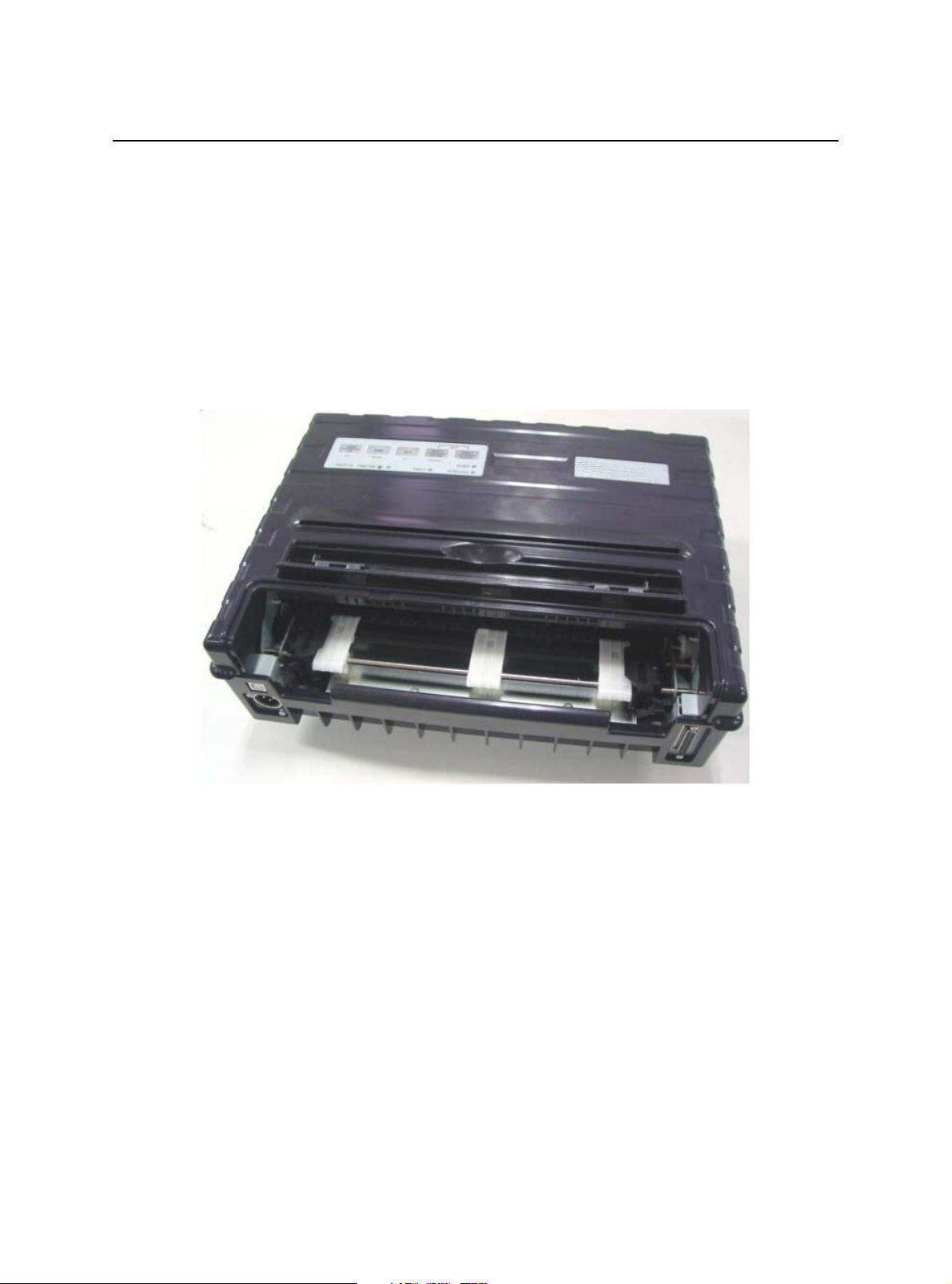
Getting to Know the Printer’s Major Parts and the Control Panel
This section describes the major parts and controls of the printer and operations of the
control panel. Take a moment to become familiar with the printer.
2-1
Page 10
Paper Handling
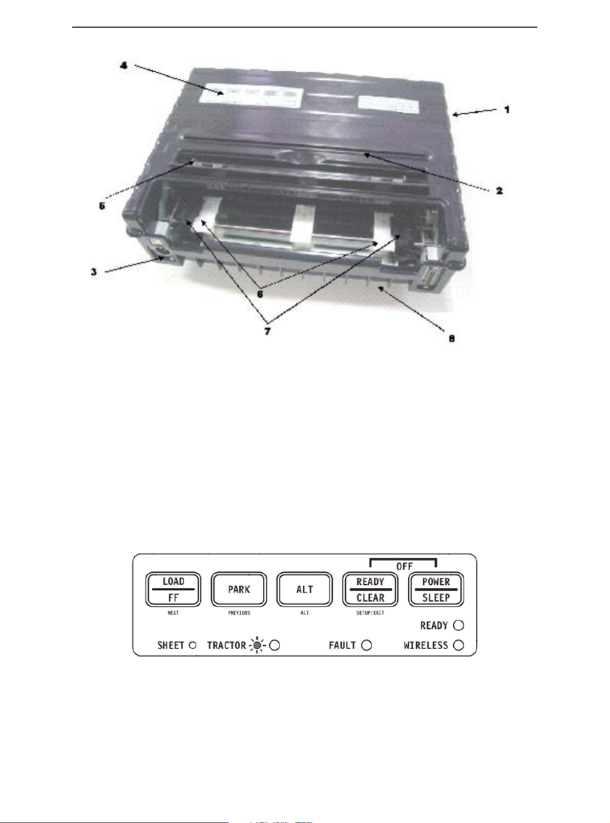
Front View
1 Top Cover
2 Cut Sheet Edge
3 Power Supply Connector (to connect to the vehicle battery)
4 Control Panel (to load and feed paper, select print features, or change the printer’s
optional settings)
5 Single Sheet Edge Guides (to adjust location of single sheets)
6 Easy Load Platforms
7 Tractor Doors (to hold and feed continuous forms)
8 Front/Bottom
2-2
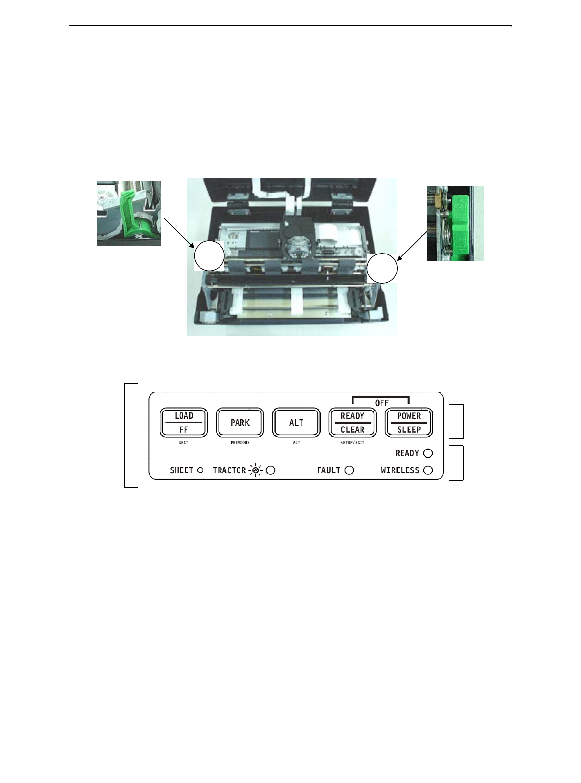
Control Panel
Page 11
Front Rear
Paper Handling
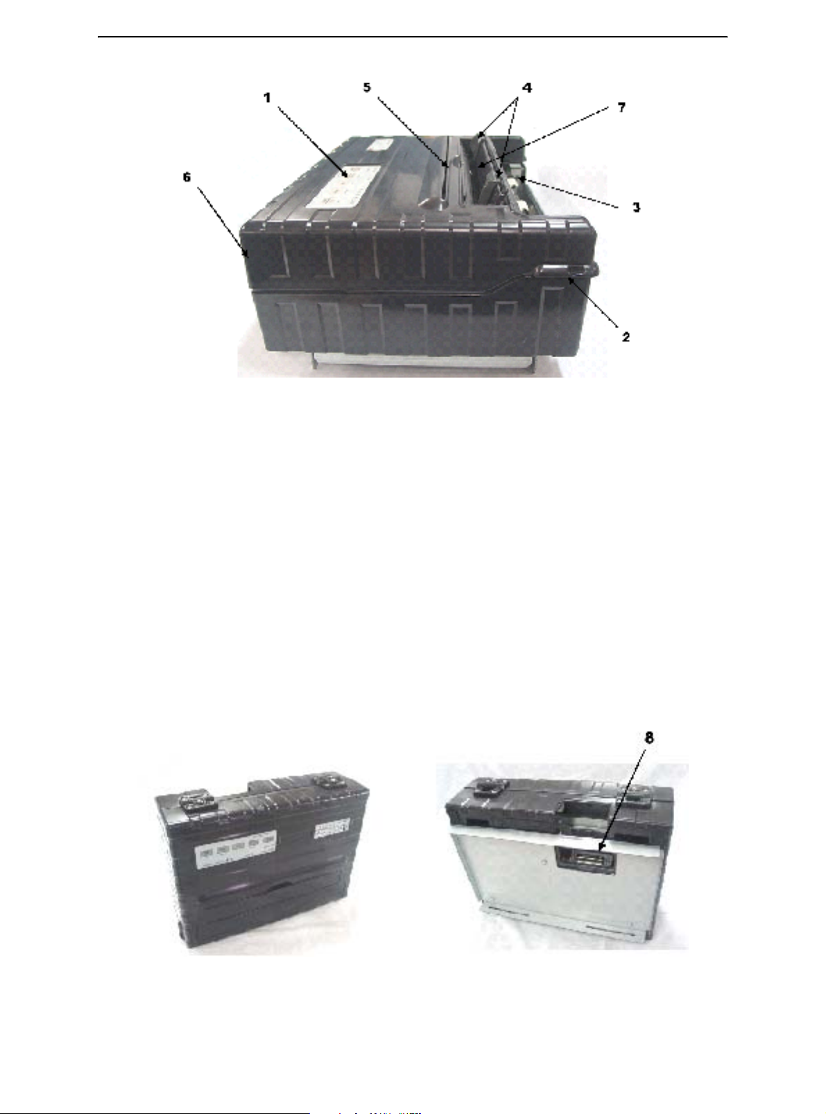
Left Side View
1 Power Switch
2 Cover Latch (to secure top cover)
3 Forms Tractors (to hold and feed continuous forms)
4 Paper Guides (to guide single sheets)
5 Paper Exit Slot and Tear Edge
6 Top Cover – Rear
7 Single Sheet Tray (Shown in down Position)
Bottom View
8 Interface Connectors (or Wireless Adapters if installed)
Vertical Position Bottom View
2-3
Page 12
Paper Handling
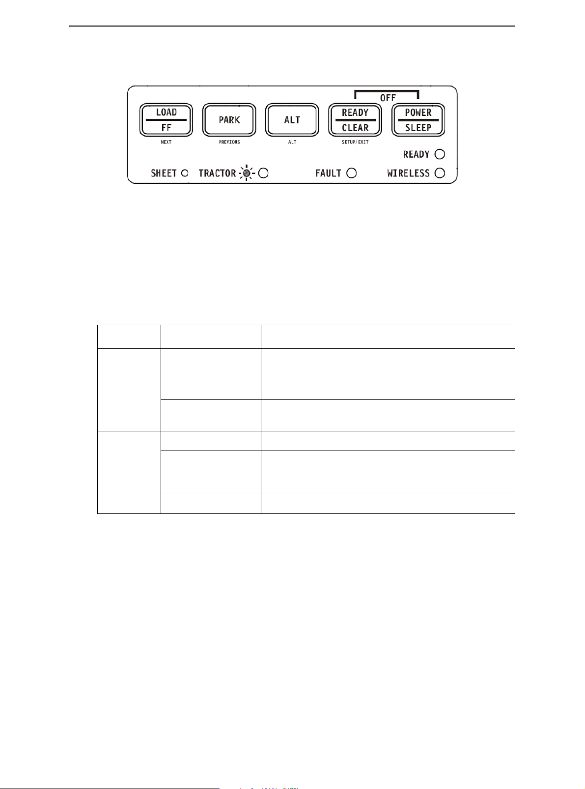
Operations of the Control Panel
This section summarizes status indications and operations of the control panel in Normal
mode. For details on Set-Up mode, see Chapter 4, “Using Set-Up Mode.”
Normal mode operation includes everyday operations, such as paper handling, font
selection, macro selection, and protocol selection. The first table lists basic states represented by the Ready and Fault indicators. The second table lists Normal mode operations and required user response. Operations are listed by functions.
Basic States of the Printer
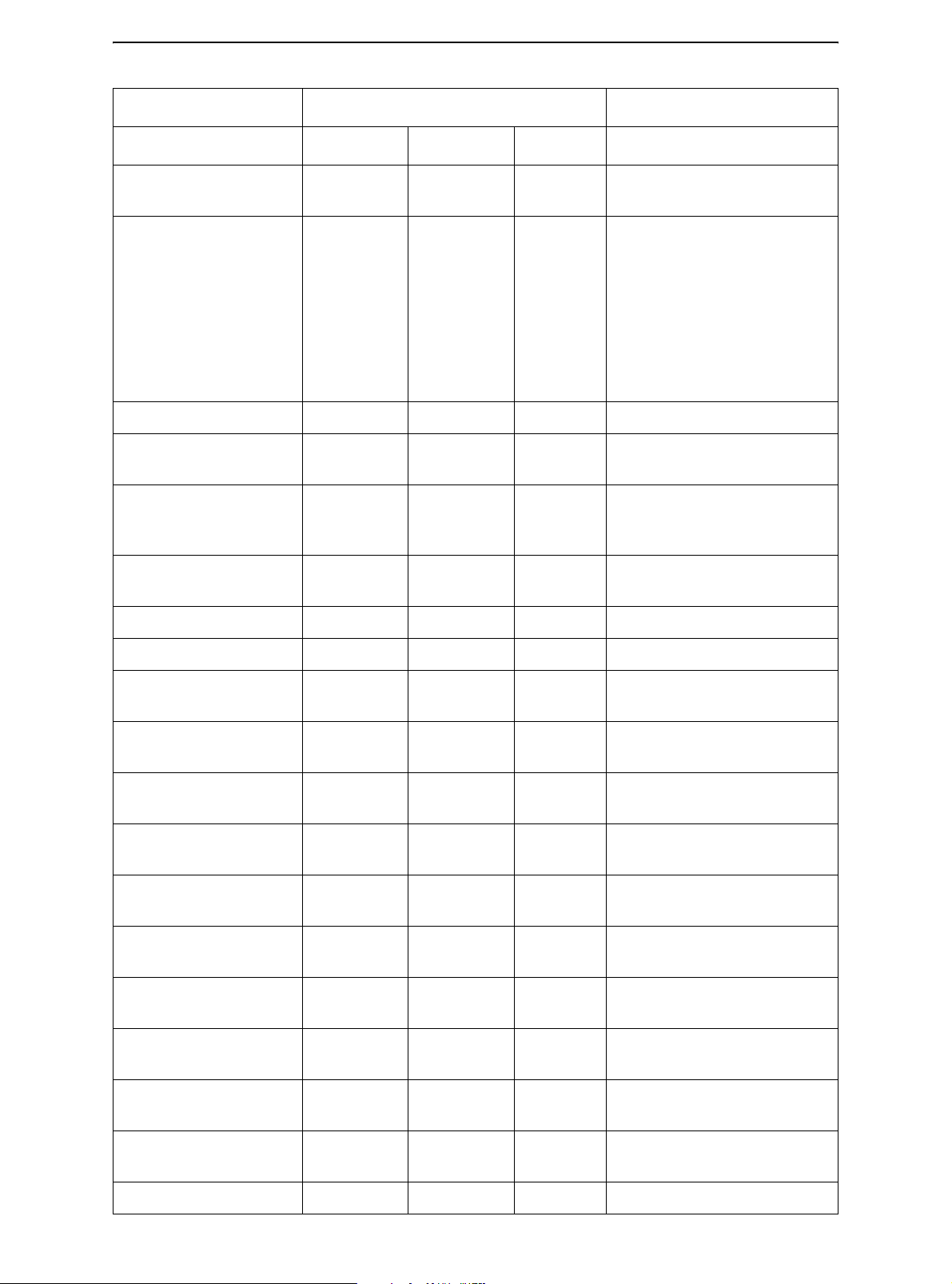
Indicator Status Printer Status
Ready On The printer is ready for printing or the printer is receiving
or printing data.
Blinking The printer is not ready and holds printing data.
Off The printer is not ready and it does not hold printing
data.
Fault On The printer is out of paper.
Blinking slowly The printer has detected an operational error: paper
jam, interface error, carriage error, paper unloading
error, etc.
Blinking fast The printer detected diagnostic errors at power-up.
2-4
Page 13
Paper Handling
Operation Required Conditions
Ready Printing
Load continuous forms
— Not printing On Press FF/LOAD.
*1
*2
Fault
Required Action
paper
Load single sheet paper — Not printing On Paper is automatically
detected and advanced (autoloading) when it is first
inserted. In this mode, if the
FF key is pushed, the inserted
sheet will be ejected from the
printer and the Fault LED will
light, indicating paper out
condition.
Feed paper a page — Not printing Off Press FF/LOAD.
Advance perforation to
— Not printing Off Press READY.
tearbar
Eject single-sheet
paper
— Not printing Off Press FF/LOAD. The Fault
LED will light, indicating a
paper out condition.
Unload continuous-
— Not printing Off Press Park.
forms paper
Pause printing On Printing Off Press READY
Resume printing Blinking Not printing Off Press READY
Resume printing after a
Off Not printing On Clear error and press READY.
fault
Resume printing after
Off Not printing On Load paper.
paper out
Place printer in Ready
Off Not printing Off Press READY
state
Place printer in pause
On — Off Press READY
state
Enter Normal mode N/A N/A N/A Turn power on without press-
ing any keys
Enter Sleep mode N/A Not printing N/A Press POWER/SLEEP for five
seconds
Leave Sleep mode N/A Not printing N/A Press POWER/SLEEP for
one second
Printing test N/A N/A N/A Turn power on while pressing
FF/LOAD key.
Use the adjustment
Off — Off Press ALT-NEXT.
temporarily
Use the adjustment
Off — Off Press SETUP/EXIT.
permanently
Clear the adjustment Off — Off Press ALT-PREVIOUS.
2-5
Page 14
Paper Handling
Operation Required Conditions
Ready Printing
*1
*2
Fault
Required Action
Enter Set-Up mode N/A N/A N/A Turn power on while pressing
SETUP/EXIT.
Move cursor to select a
Set-Up Function or
Off Not printing Off Press NEXT or PREVIOUS
key.
Value
Move cursor to select a
Set-Up Option
Select a Set-Up Function or Value
Select a Set-Up Value
Off Not printing Off Press NEXT or PREVIOUS
key.
Off Not printing Off Press ALT-NEXT or ALT-
PREVIOUS key.
Off Not printing Off Press SETUP/EXIT.
and move cursor to
SAVE&EXIT
Clear software-detected
— — Blinking Press SETUP/EXIT
errors
Initialize the printer — — — Turn power off and on again.
*1 In Normal mode operation, all keys except READY are inactive in the Busy state in which the printer is receiving or printing
data.
*2 Not printing includes the following situations: the printer is ready and awaiting data, or the READY key is pressed and the
printer is awaiting data, or the READY key is pressed during printing.
2-6
Page 15
Paper Handling
Selecting Paper
The printer can handle either single sheets or continuous forms. Single sheets, also
called cut sheets, include envelopes and non-continuous, multipart forms. Continuous
forms include labels and multipart forms fed into the printer using the forms tractors.
For best results, use paper that meets the specifications listed in the following table. (See
Appendix B, “Printer and Paper Specifications,” for detailed specifications.) If you are
unsure of the suitability of a particular type of paper, try testing the paper or consult your
dealer.
Paper Specifications
Paper Size
Parameter Fixed Unit Portable Unit
Width -- Cut Sheet 102 to 267 mm 102 to 248 mm
Width -- Fan-Fold 102 to 216 mm 102 to 216 mm
Length 102 mm or greater 102 to 279 mm
Thickness Up to 0.35 mm Up to 0.35 mm
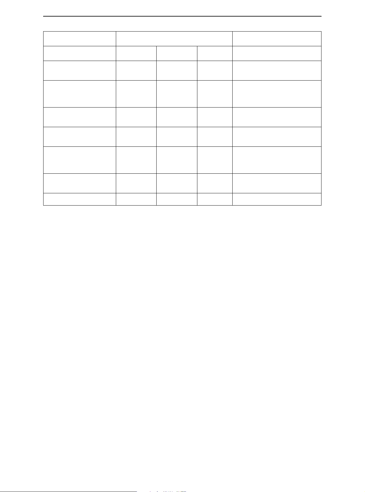
Paper Thickness and Number of Copies
Description
Thickness 0.35 mm (0.014 in) maximum total thickness.
Copies 1 to 3 copies, including the original. For carbon-inter-
leaved paper, the carbon counts as a copy.
2-7
Page 16
Paper Handling
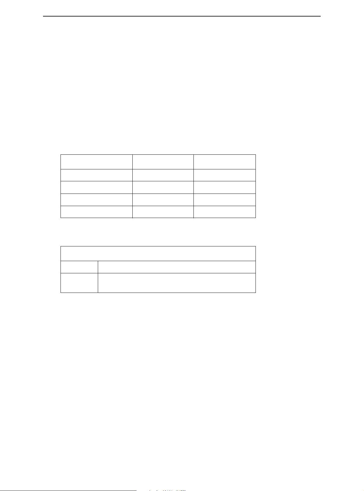
Overview of Paper Operations
The following levers and keys are used in paper handling. Lift the cover to locate these
levers inside the printer.
• Print Gap lever on the left side under the cover
• Paper Select lever on the right side under the cover
The following figure shows the location of each lever, indicators, and keys:
Print Gap Lever
Paper Select
Lever
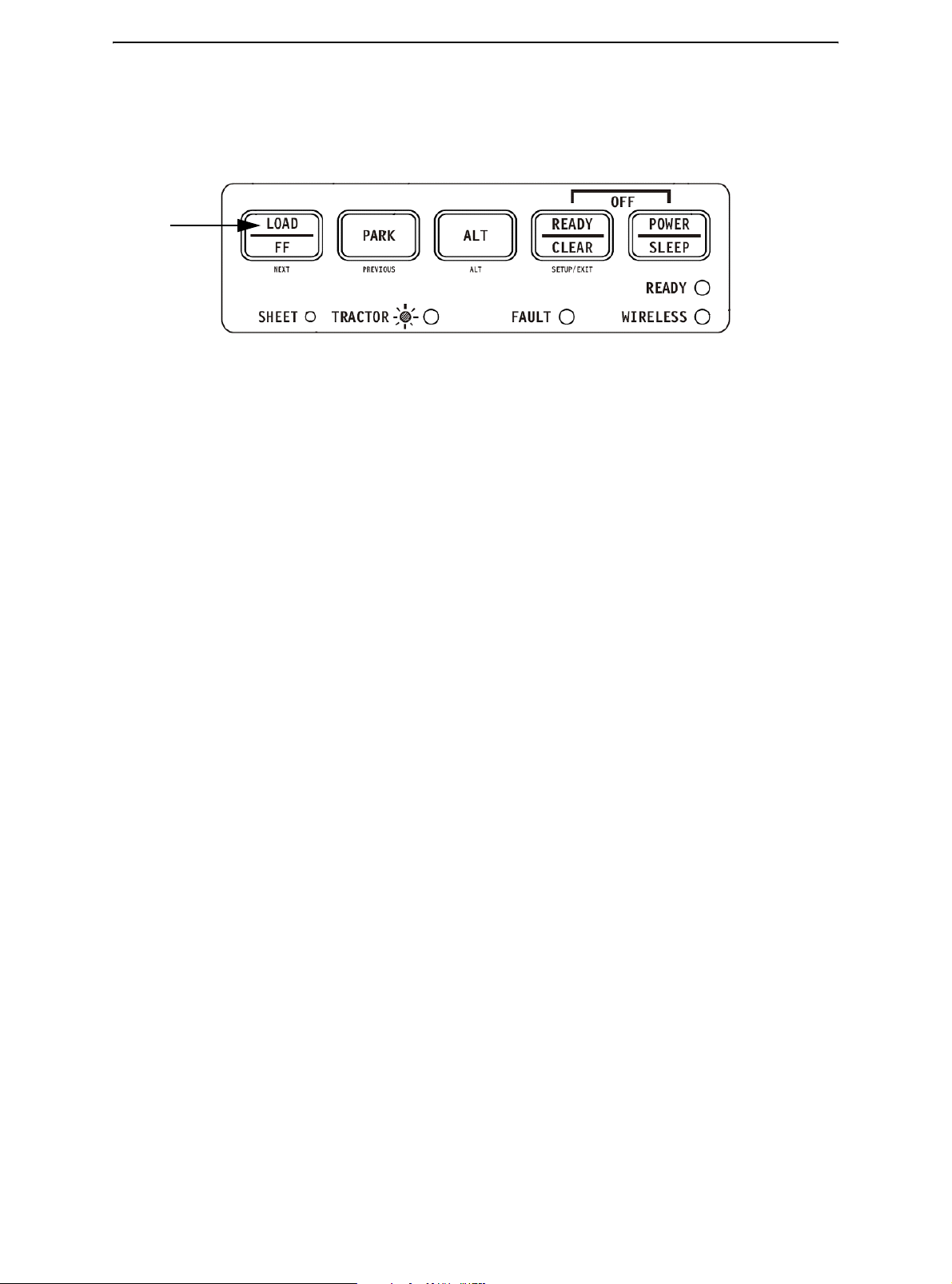
• All keys on the control panel for primary and alternative functions are labeled below
and above respectively.
Control
Panel
Printer Controls and keys
Control
keys
Indicator
Lights
2-8
Page 17
Paper Handling
The following table summarizes the use of levers and keys in paper handling. More
detailed information is provided later in this chapter.
CAUTION: To load or feed paper, the printer must be:
• In the Ready state but not receiving or printing data
• In the Pause state
Levers and keys used for Paper Handling
Lever/key Purpose Action
FF/LOAD Form Feed Press FF/LOAD to execute a form
feed. Continuous forms are fed
forward by one page. Single sheets
are ejected.
Load paper Press FF/LOAD to feed paper to the
top of form position.
PARK Unload forms Press PARK to retract continuous
forms to the “park position.”
SETUP/EXIT + ALT Enter Top-of-Form (TOF)
Adjustment mode
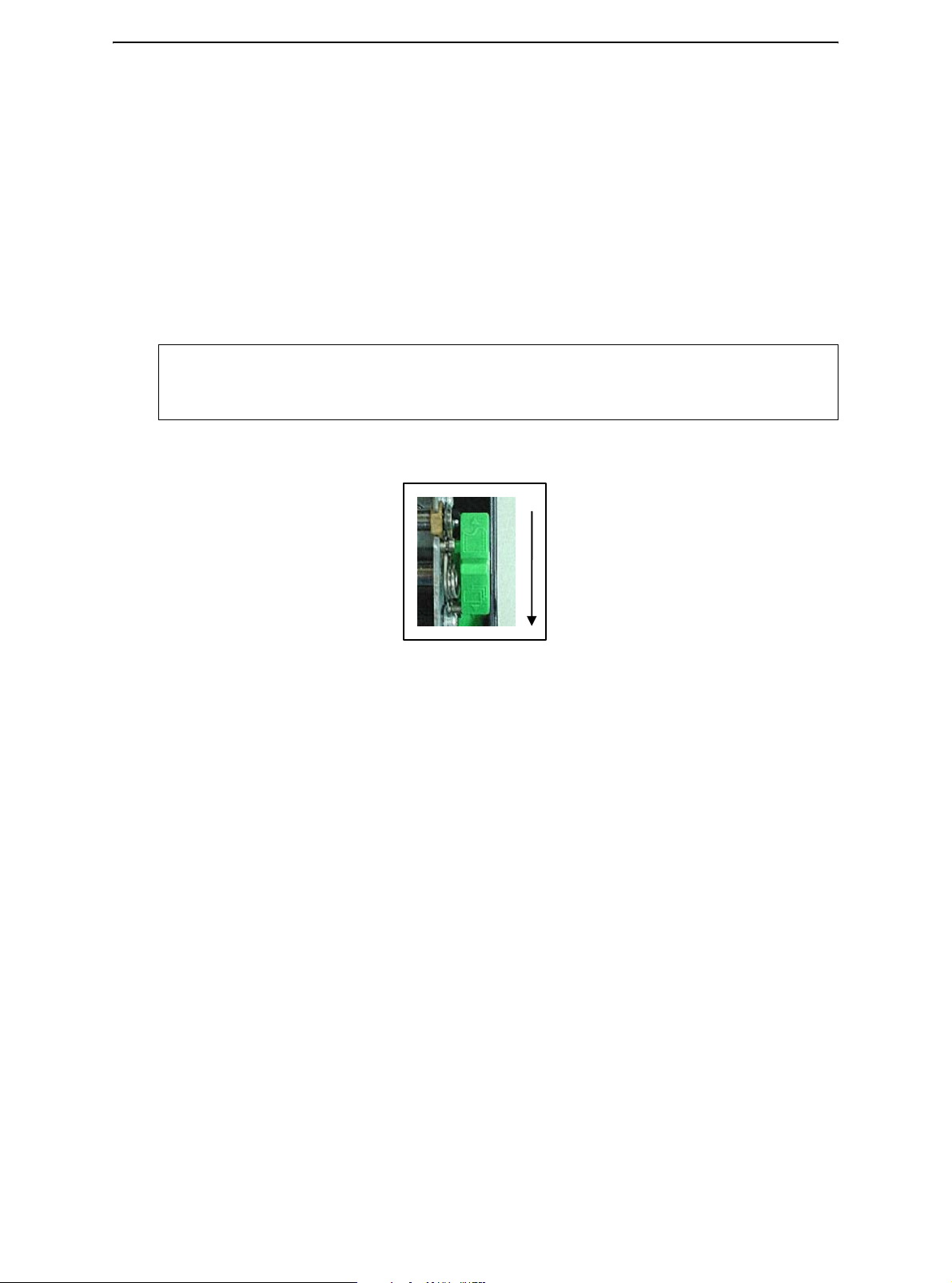
Paper select lever * Select paper path Move the paper select lever back-
Press SETUP/EXIT and ALT at the
same time to enter TOF Adjustment
mode where the paper loading position can be adjusted. See Top-ofForm Adjustment later in this chapter.
ward for continuous sheets. Move the
paper select lever forward for single
forms.
* The following graphics are engraved on the casing.
Continuous Forms Single Sheet
2-9
Page 18
Paper Handling
Adjusting for Paper Thickness
The printer can handle paper with different thicknesses, including multipart forms with up
to four parts (original plus three copies). For details on paper thickness specifications,
see Appendix B “Printer and Paper Specifications.”
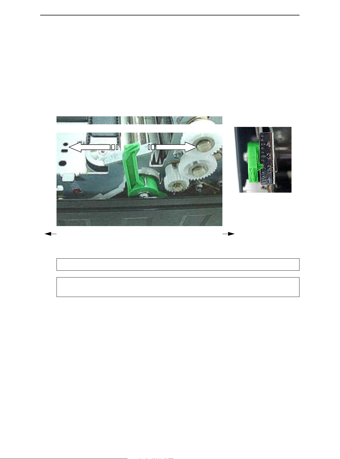
The Print Gap lever, located on the left under the cover, allows you to adjust for different
paper thicknesses. Be sure to adjust the Print Gap lever whenever you change the
number of copies being printed.
The print gap lever has twelve settings.
Moving the Print Gap lever to front of printer reduces the Print Gap.
Thicker Form Print Gap Lever Thinner Form
Rear of Printer Left Side View Front of Printer
Larger Print Gap
Smaller Print Gap
Adjusting the Print Gap Lever
Important: Open Print Gap lever to maximum to replace ribbon.
CAUTION: If printing smears, the ribbon misfeeds, or the paper jams, move the lever
one position wider.
2-10
Page 19
Paper Handling
Using Continuous Forms
Continuous forms paper, fanfolded at the horizontal perforations, is ideal for printing
rough drafts, long files, forms and invoices. The paper is fed into the printer using the
forms tractor unit. The Push tractor is at the front/bottom of the printer. The paper is
loaded and adjusted via keys. The forms may be advanced to tear off position by operator
or automatically through a timeout.
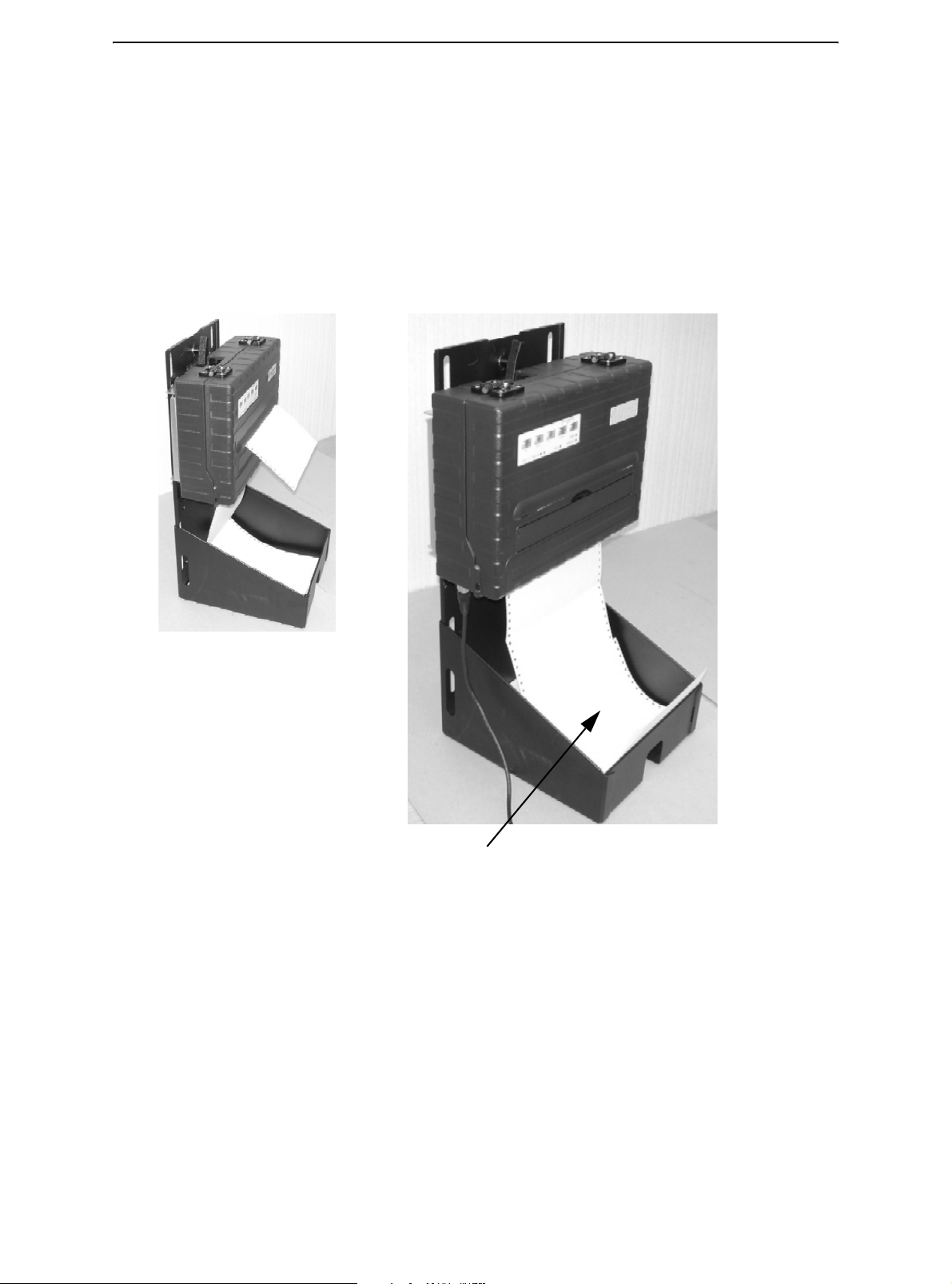
Positioning the Paper Stack
Place the stack of continuous forms paper as shown in the picture below.
Side View
Continuous Form Paper Stack
2-11
Page 20
Paper Handling
Loading Continuous Forms (Push Tractor)
This section explains how to use continuous forms with a push tractor at rear (or bottom,
depending on printer orientation). Paper is loaded and adjusted via keys. Forms may be
advanced to tear off feature by operator or by host.
To load continuous forms paper:
1 Make sure that the printer is turned on. Remove any single-sheet paper from the
printer.
2 If necessary, readjust the Print Gap lever for continuous forms. (See the section
“Adjusting for Paper Thickness” earlier in this chapter.)
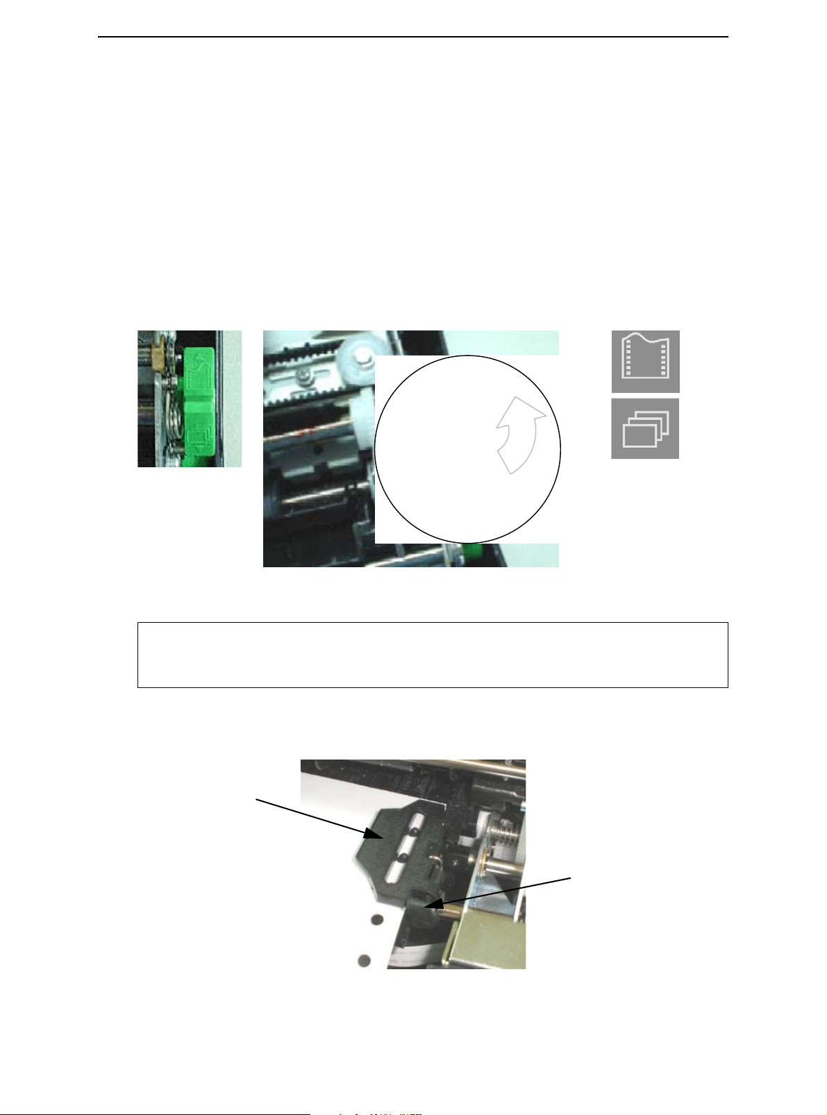
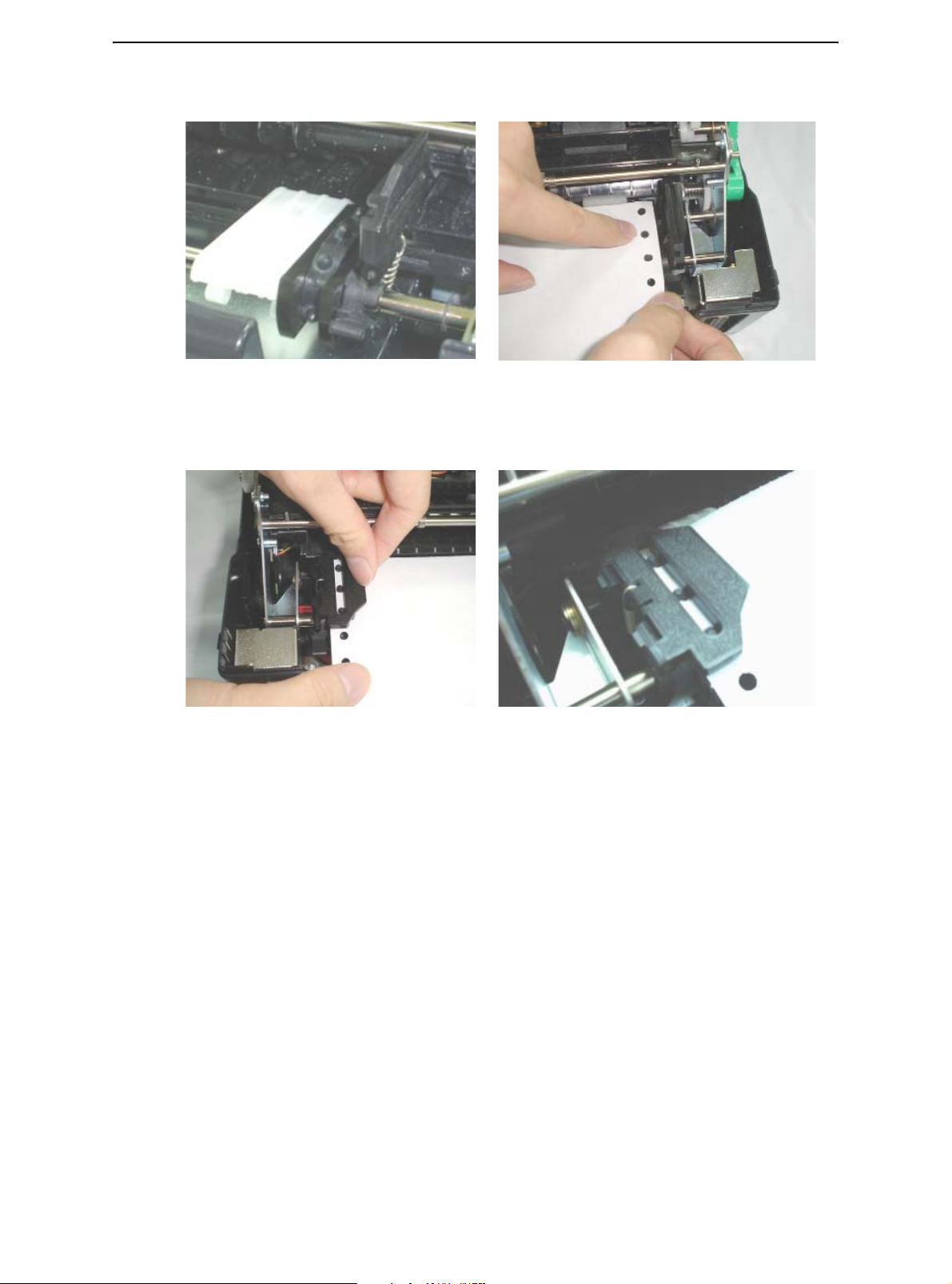
3 Move the paper select lever backward to Continuous Paper position.
Rear of Printer
Paper Select Lever
Front of Printer
Continuous
Single Sheet
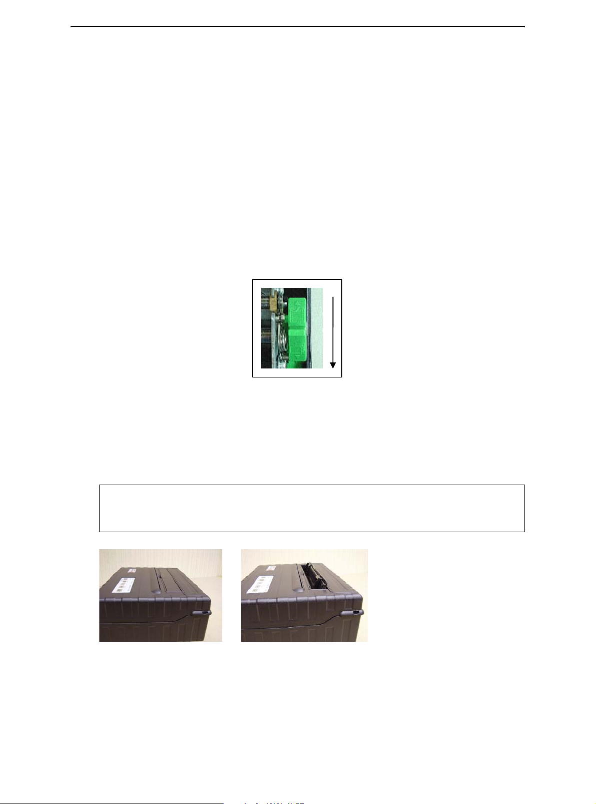
NOTE: For improved viewing of tractors, you may move the Paper Support to the full-
up (Position 3) position. After loading the paper, move it back to the full-down
(Position 1) position.
4 Release the tractor locking levers by pulling them up. Once the right forms tractor is
positioned, lock it by pushing down its locking lever.
2-12
Tractor Door
Tractor Locking Lever
Page 21
Paper Handling
5 Raise the tractor doors and fit the first two paper feed holes onto the right tractor pins.
6 Holding paper against the Easy-Load Platform, fit the paper into the tractor. Close the
tractor Door. Repeat the procedure for the left tractor and adjust the left forms tractor
to accommodate the width of the form.
7 Move the left tractor to make the paper flat. Do not stretch the paper too taut. Push
the left locking lever down to secure the tractor in place.
8 Press the FF/LOAD key to advance the paper to the top-of-form position from which
printing can start. The printer is automatically placed in the Ready State.
9 Press the READY key to place the printer on line. Print a sample page and check the
page margins. Make the following adjustments, as necessary:
• Horizontal alignment. Move the forms tractors as required with paper parked.
• Top-of-form setting. Use the printer Set-Up mode (see Chapter 4, “using the Set-
Up Mode”).
• Margin settings. Use your software or the printer Set-Up mode (see Chapter 4,
“using Set-Up Mode”).
2-13
Page 22

Paper Handling
Unloading Continuous Forms
To unload continuous forms:
1 Make sure that the Paper Select lever is set to the continuous forms position.
2 Press the PARK key. The continuous forms paper is retracted to the park position. If
the paper cannot be retracted in one operation, continue to press the PARK key until
the paper is parked.
NOTE: The printer can retract continuous forms-paper by a recommended maximum
of 25.4 cm (11 inches) per operation
3 To remove the paper, raise the Tractor Doors and lift out the paper.
Recovering from an Unexpected Unloading Operation
If you have accidentally pressed the PARK key, you can cancel this operation in two ways
only if this unexpected operation was unsuccessful (the paper was not actually parked,
and the Fault indicator is blinking).
• Press the READY key. The printer switches to the Ready state and the paper moves
according to the setting of the Set-Up option.
• Press the FF/LOAD key. The paper moves back to the place it was positioned before
you pressed the PARK key.
Automatic-Tear-Off Advancing
Your printer has a tear bar that allows you to tear off printed pages without wasting paper.
The tear bar is at the rear edge of the paper exit slot.
Your printer is factory-set for automatic tear-off. When a printing job ends (including a
form feed command), the bottom perforation of the last printed page is automatically positioned in front of the tear bar. The printed page may now be pulled against the tear bar
of the tope cover. You can change the positioning delay from one to five seconds, using
the Set-Up mode.
Manual Tear-Off Advancing
If you have set the TEAR option of the INSTALL function to MANUAL, tear off the paper
by:
1 Press the READY to put the printer in pause mode. The printer will position the paper
perforation in front of the tear bar.
CAUTION: If the paper perforation is not positioned in front of the tear bar, the length
of your paper may not be specified correctly in your software or the SetUp mode. Check that the paper length is specified correctly. For information on specifying page length using the Set-Up mode, see Chapter 4,
“Using Set-Up Mode.”
2-14
Page 23
Paper Handling
2 Tear the paper off at the perforation by pulling the paper to the rear, against the tear
edge.
Tearing Off Continuous Forms
2-15
Page 24
Paper Handling
Using Single Sheets
This section describes how to load paper in the Single Sheet Paper Tray. The Single
Sheet Paper Tray allows paper to be loaded manually, one sheet at a time.
Loading a Single Sheet of Paper
To load a sheet of paper using the Single sheet Paper Tray:
1 Make sure that the printer is turned on. Check that tractor-fed continuous forms are
retracted to the park position. (For details, see the section, “Unloading Continuous
Forms,” later in this chapter.)
2 If necessary, reset the Print Gap lever. (See the section, “Adjusting for Paper Thick-
ness,” earlier in this chapter.)
3 Move the Paper Select lever toward front of printer. (This lever is at the right under
the cover.)
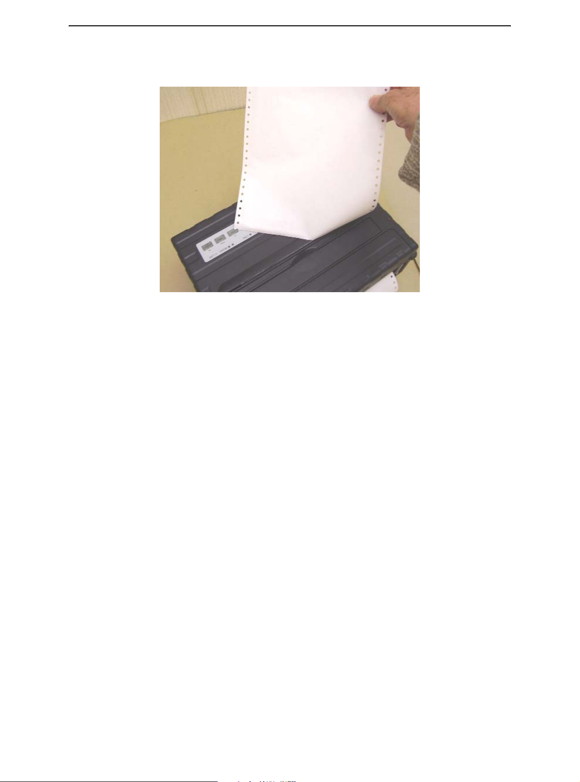
4 Raise the Single Sheet Paper Tray until it locks in Paper Support Position 2.
5 Line up the right sliding edge guide with the notch on the Paper Support. Adjust the
left sliding edge guide to the width of the paper. Insert the sheet into the raised Paper
Support. Make sure that the bottom edge of the paper engages snugly with the platen.
The paper will automatically advance to the top-of-form position if the Single Sheet
Load option of the Set-Up mode is set to Automatic.
NOTE: The factory setting for the Single Sheet Load option is automatic loading after
paper detection. If you set this option to manual, you will have to press FF/
LOAD to feed the paper.
Paper Support Position 1
Operating and tear-off
using continuous forms
Paper Support Position 2
Loading Single Sheets
6 Place the printer in the Ready state. Print a sample page and check the page margins.
Make the following adjustments, as necessary:
• Horizontal alignment. Readjust the paper guides if required.
2-16
Page 25

Paper Handling
• Top-of-form setting. Use the printer Set-Up mode (see Chapter 4, “Using Set-Up
Mode,”).
• Margin settings. Use your software or the printer Set-Up mode (see Chapter 4,
“Using Set-Up Mode”).
Ejecting Single Sheets
If you print using software which inserts a form feed at the end of each page, each sheet
is ejected automatically upon the completion of the page printing. To manually eject
sheets of paper:
• Press the FF key to execute a forward form feed.
NOTE: If the printing job does not include a form feed command, the paper is auto-
matically fed so that you can see the last printed line.
2-17
Page 26

Paper Handling
Feeding and Positioning Paper
Print Area Definition
•
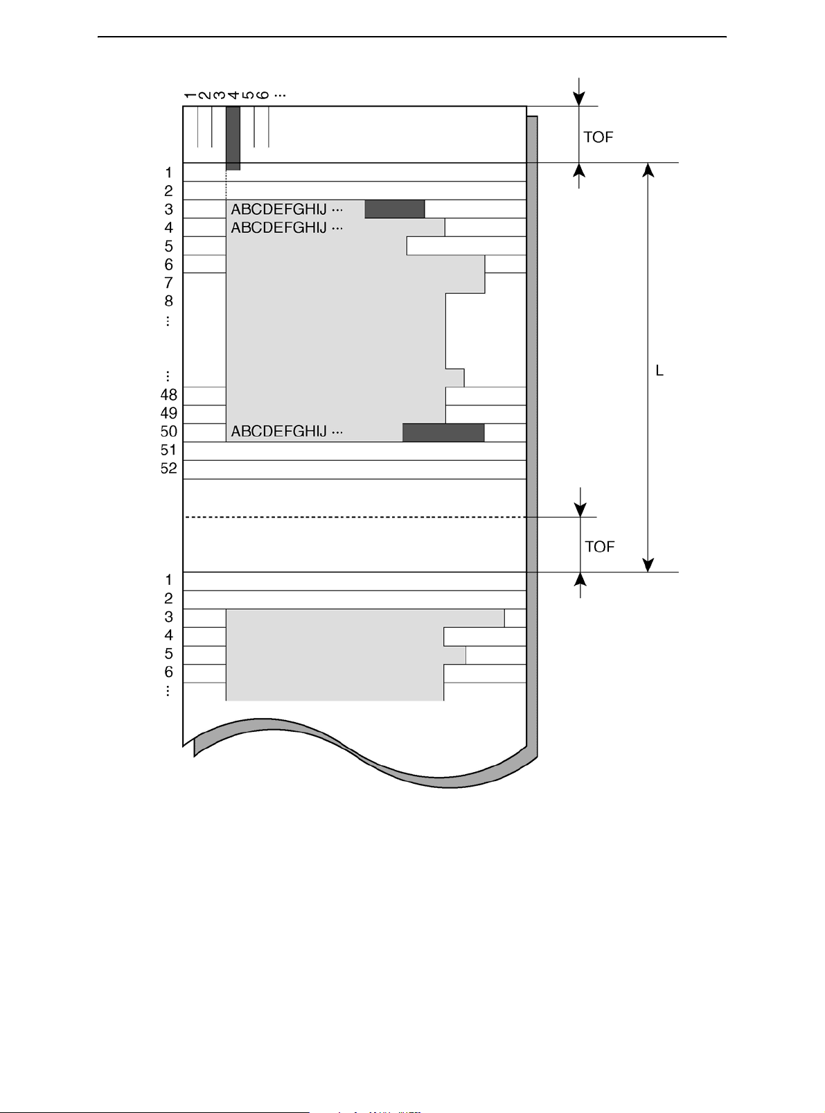
Top-of-Form: This value defines the distance between the edge of the paper and the
place where you allow the printing to begin (position of line number 1). You can adjust
this distance according to the condition of your paper (for example, pre-printed forms).
When you load the paper, the printer feeds the paper to this position, waiting for printing commands.
• Form Length: Set the corresponding Set-Up option (FORM LENGTH) according to the
actual physical page length (distance between two perforations for continuous forms).
This will allow the printer to know exactly where the print head is and to position it at
the same position when a form feed occurs.
• Top line: This is the line where the printing actually starts. To define a top margin,
select the number of this line within Set-Up mode (TOP MRGN option). Example: In
the following picture, TOP MRGN option is set to 3.
• Bottom line: This is the line where the printing actually stops. To define a bottom
margin, select the number of this line within Set-Up mode (BOTTOM MRG option).
Example: In the following picture, BOTTOM MRG option is set to 50.
• Left column: This is the column where the printing actually starts. To define a left
margin, select the number of this column within Set-Up mode (LEFT MARGN option).
Example: In the following picture, LEFT MARGN option is set to 4.
• Print area: Print area defined by the corresponding Set-Up options: Form Length, Top-
of-Form, Top Margin, and Bottom Margin.
• Paper perforation: The perforation defines the physical page length.
2-18
Page 27
Paper Handling
Print Area Definition
Form Feed
Use the form feed function to move paper forward. This function is valid whenever the
printer is not receiving or printing data and has no fault. Pressing the FF/LOAD key feeds
the paper to the next Top-of-form position.
2-19
Page 28
Paper Handling
Switching Paper Types
If you have more than one type of job, it is often necessary to switch between continuous
forms and single sheets. This section explains how to switch between paper types. It is
not necessary to remove the continuous forms paper from the printer.
Switching from Continuous Forms to Single Sheets
To switch from continuous forms to single sheets:
1 Tear off your printed pages.
2 Retract the forms paper to the park position by pressing the Park key. The Fault indi-
cator turns on.
CAUTION: Retracting many pages by using the Park key without tearing off may
cause paper jams. To avoid damage to your printed pages, be sure to tear
off the printed pages before retracting the continuous forms paper.
3 Move the Paper Select lever to the single sheet position.
4 Raise the Paper tray support and guide to tray position 2. (For details, see the section,
“Using Single Sheets,” earlier in this chapter.) Put a sheet of paper on the Paper
support and guide with its bottom edge aligned with the platen. The paper is automatically detected and advanced (if the Single Sheet Load Option is set to automatic)
when it is first inserted to the top-of-form position. In this mode, if the FF/LOAD key is
pushed, the inserted sheet will be ejected from the printer and the Fault LED will light,
indicating a paper out condition.
You are now ready to print using single sheets.
2-20
Page 29
Paper Handling
Switching from Single Sheets to Continuous Forms
To switch from single sheets to continuous forms:
1 If a sheet of paper is loaded, remove the paper by pressing the FF/LOAD key.
2 Move the Paper Select lever to the continuous forms position.
3 Press the FF/LOAD key. The continuous forms paper advances from the park posi-
tion to the top-of-form position.
You are now ready to print using continuous forms paper.
Tips on Paper Handling
General Tips
•
Use high-quality paper. Do not use paper that is wrinkled or curled at the edges.
• Do not use paper with staples or metal parts.
• Do not use paper with unpredictable variations in thickness, such as paper with partial
multilayers, paper with embossed printing.
• Store paper in a clean, dry environment.
Multipart Forms
•
Avoid using carbon-interleaved single sheets if possible. Printing tends to become
misaligned on the bottom sheet.
• Set the paper thickness lever to best accommodate the multipart form thickness.
2-21
Page 30

Page 31

3
Printing
This chapter describes the following typical printing operations:
• Starting, stopping, or resuming printing and viewing last printed lines
• Removing printed pages
The PARK, LOAD and the READY keys are used for these operations, which are described in detail in this section. For a summary of the operation of these keys, see the section, “Getting to Know the Printer’s Major Parts and the Control Panel,” in Chapter 2,
“Paper Handling.”
Instructions for loading and handling paper are also given in Chapter 2, “Paper Handling.”
This chapter also describes how to set the printer into the sleep mode.
Using the Control Panel
Some print features can be selected from the control panel. These features are, two predetermined sets (macros) of print features, and two emulations.
Printer Control Panel
3-1
Page 32

Printing
Starting or Stopping Printing
Starting Printing
Before you start to print, make sure that paper is loaded. Also, verify that the Print Gap
lever is set to the appropriate position.
To start printing, make sure that the Ready indicator is lit (the printer is ready). If not so,
press the READY key to place the printer in the Ready state. Start your print job.
Stopping and Viewing Printing
To stop printing, press the READY key to place the printer in the Pause state. The printer
stops after printing the current and next lines. You can also use your software to stop printing, but there will be a slight delay before printing stops. After the printer enters the Pause state, it still receives data until the print buffer becomes full of new data.
CAUTION: The data in the print buffer will be lost if you turn the printer off.
When the printer stops printing, the paper is advanced to the viewing position so that you
can view the last printed lines. This function is valid for single sheets and continuous
forms in push-tractor feed mode.
Resuming Printing
To resume printing, press the READY key again. If the paper is advanced for viewing, it
is backed up to the previous position before printing. To cancel printing, use the cancel
commands provided by your software or computer. To clear the print buffer, turn the printer off.
CAUTION: Any data sent to the print buffer before you canceled printing will be lost.
Resuming from a Paper-Out
The printer can “sense” when paper runs out. The printer stops printing and lights the
Fault indicator. To resume printing when paper runs out, follow the procedures described
below:
1 Install paper on the forms tractor unit or on the cut sheet stand as described in Chap-
ter 2, “Paper Handling.”
2 To load the first sheet of paper, press the FF/LOAD key for continuous forms. Single
sheets are automatically loaded unless you change the factory default setting. The
Fault indicator will turn off and the printer resumes printing.
3-2
Page 33

Removing Printed Pages
This section describes the best methods for removing single sheets or continuous forms
paper after printing.
Removing Single Sheets
When you print using software, the printer automatically ejects each sheet of paper when
the end of the printed page is reached. To eject sheets manually:
• Press the FF/Load key to execute a form feed.
NOTE: Proper use of the Tear-off function requires the paper be positioned at Top of
Form either by software command (form Feed) or by pressing the FF/Load
key.
If you have set the TEAR option to MANUAL, use the READY key to control the Tear-Off
function.
NOTE: See the section “Tearing Off Continuous Forms” in Chapter 2, “Paper
Handling”.
Printing
3-3
Page 34

Printing
Sleep Mode
The printer has a power saving feature (Sleep Mode). If the printer is in sleep mode state,
the power consumption is lowered to 2W instead of 7W in normal mode. This feature is
usefull if you want to save energy of the car battery.
If the printer receives data while in sleep mode, it automatically is set to normal mode and
ready to print.
NOTE: If any interface is connected to the parallel port of the printer, this interface will
be turned off while entering the power saving condition.
Entering Sleep Mode
To enter the Sleep Mode:
• Press and hold depressed the POWER/SLEEP key for five seconds to enter Sleep
Mode.
NOTE: You can adjust the duration of time after which the printer automatically enters
Sleep Mode in Set-Up mode via the option <PWRDWNHRS>. See the section
“INSTALL Options and Values” in Chapter 4, “Using Special Mode”.
While in sleep mode, the READY LED blinks slowly (all 5 seconds), all other LEDs of the
control panel are off.
Leaving Sleep Mode
To leave the Sleep Mode:
• Press the POWER/SLEEP key for one second to leave Sleep Mode or send data to
the serial, USB or internal Bluetooth module.
3-4
Page 35

4
Using Special Mode
Your Mobile Printer has two operation modes:
• The Normal mode is used for daily operations like paper handling and printing as ex-
plained in Chapter 2, “Paper Handling," and Chapter 3, “Printing.”
• The Special mode is used to change the printer settings.
The following table summarizes the purpose of each function.
Special Mode Functions
Function Purpose
Setup Mode Change the Printer setting
Print Configuration Print the Printer Configuration
To check your settings by printing a list of all the printer’s currently selected values.
Printing Test Run the printing test
Hex Dump Mode Hex-dump allows you to determine whether the computer is
sending the correct commands to the printer
Printing Alignment Adjustment
Top of Form Adjustment Perform adjustment of Top of Form
Setting of The First Dot Position on The Left Side
Menu-Access Restricts access to Set-Up functions from the control panel
Setting Setup Mode to
Default Value (Standard)
Setting Setup Mode to
Default Value (6820)
Perform adjustment Bi-directional alignment
Change the left margin fine adjustment
Resets factory settings in MACRO and INSTALL for standard
Resets factory settings in MACRO and INSTALL for 6820
4-1
Page 36

Using Special Mode
Entering Special Mode
To enter Special mode:
1 Make sure that the tractors are loaded with continuous feed paper and that the paper
select lever is set backward.
2 Turn the printer off.
3 Turn the printer back on while pressing each keys.
Function
Setup Mode
Print Configuration
Printing Test
Hex Dump Mode
Printing Alignment Adjustment
Top Adjustment
Setting of The First Dot Position on The Left
Side
Menu-Access
Setting Setup Mode to Default Value (Standard)
Setting Setup Mode to Default Value (6820)
Load/
FF
Park Alt
Ready/
Clear
•
•
•
••
••
•
•••
•••
••
••
4-2
Page 37

Using Special Mode
Set-Up Mode Function
The Set-Up mode allows you:
• To define a user environment, Macro, which is a printer operating environment for your
application software. The printer operating environment includes the emulation, font,
horizontal and vertical pitches, page length and margins, line mode, and printing direction. It also includes emulation dependent options like the character set.
• To define general installation parameters related to the integration in your environment
(e.g., menu language, tear-off control, auto-load control, and interface).
• To recall all the factory settings (including the user environment and installation param-
eters).
• To define what kind of settings modifications are allowed to avoid accidentally chang-
ing of Set-Up values.
NOTE: You may want to use the flowchart at the end of this chapter for quick refer-
ence. The flowchart lists all printer Set-Up functions, options, and values.
How Set-Up Works
The Set-Up mode consists of Set-Up functions which correspond to the printer settings
described in the previous page. Each function generally has many options which correspond to the print features to be changed. Each option includes many parameters values
to be selected. All the Set-Up functions, options, and values are printed in a logical sequence on the paper when you enter the Set-Up mode, including the usage of keys. You
can perform all the Set-Up operations by using keys on the control panel in the following
order:
• Navigating through the option menu structure.
• Selecting a new value for an option.
• Saving your new printer configuration (permanently or temporarily).
4-3
Page 38

Using Special Mode
Entering the Set-Up Mode
To enter the Set-Up mode:
1 Make sure that the tractors are loaded with continuous feed paper and that the paper
select lever is set backward.
2 Turn the printer off.
3 Turn the printer back on while pressing the READY key.
Buttons Set-Up Action
NEXT Move cursor Down to the next Function or Value
PREVIOUS Move cursor Up to the next Function or Value
ALT-NEXT Select the Option or Value and Move cursor Right
1
ALT-PREVIOUS Select the Option or Value and Move cursor Left
SETUP/EXIT Select the Option or value and Move to SAVE&EXIT
FUNCTIONS
2
MACRO
The initial printout contains a header, help menu 1, and <FUNCTIONS> menu 2. The
header tells you that the printer is in the Set-Up mode. The help menu provides a quick
summary of how to use keys in the Set-Up mode.
The <FUNCTIONS> menu 2 is started from MACRO.
4-4
Page 39

Using Special Mode
Overview of the Set-Up Mode
Your Mobile Printer has five functions menu in setup mode.
When you press the NEXT KEY or PREVIOUS KEY, the following next or previous
<FUNCTIONS> menu is printed:
<FUNCTIONS>
MACRO
INSTALL
SAFE PANEL
RCALL-FACT
SAVE&EXIT
The following table summarizes the purpose of each function.
Set-Up Mode Functions
Function Description
MACRO Assigns print features to MACRO
INSTALL Changes the Set-Up menu language, computer interface, and
paper feed control options
SAFE PANEL READY, PARK and LOAD require the ALT key to be used as a two
key operation for these functions
RCALL-FACT Resets factory settings in MACRO and INSTALL
SAVE&EXIT Exits the Set-Up mode and saves any changes made in the Set-Up
mode
4-5
Page 40

Using Special Mode
To select a function from the <FUNCTIONS> menu:
1 Repeatedly press the NEXT key or the PREVIOUS key to position the function you
require.
2 Press the ALT-NEXT key or the ALT-PREVIOUS key to select the function. The print-
er prints the first option. The MACRO, INSTALL and SAFE PANEL functions contain
options that have selectable values. The other functions have neither options nor values. Repeatedly press the NEXT key or the PREVIOUS key to position the option you
require.
The first four Macro options are shown below.
<FUNCTIONS>
MACRO
<EMULATIONS>
<EMUL SERIAL>
<EMUL USB>
<EMUL WIRELESS>
3 Press the ALT-NEXT key or the ALT-PREVIOUS key to select the option. The printer
prints the first value. Repeatedly press the NEXT key or the PREVIOUS key to position the value you require.
The EMUL WIRELESS values are shown below.
<FUNCTIONS>
MACRO
<EMULATION>
<EMUL SERIAL>
<EMUL USB>
<EMUL WIRELESS>
EPSON-EP2
IBM2390+
4-6
Page 41

Using Special Mode
Options with Pre-determined Values
For some options, you can choose among a limited set of pre-determined values. To select such a value:
1 Repeatedly press the NEXT key or the PREVIOUS key to position the value you re-
quire.
2 Press the ALT-PREVIOUS key to select the value. The printer prints the current op-
tion.
3 After selecting the desired values, press the SETUP/EXIT key to reprint the <FUNC-
TIONS> SAVE&EXIT.
Example: Changing the Vertical Pitch
To become familiar with the Set-Up mode, try the following example. This example shows
how to change the vertical pitch in Macro from 6 lines per inch to 8 lines per inch.
1 Enter the Set-Up mode.
Turn the printer off and back on while pressing the READY key.
2 Select the Macro function.
Wait for the printer to stop printing and press the ALT-NEXT key to select the Macro
function and print the <EMULATION> option.
3 Print the menu of the vertical pitch option.
Since you only want to change the vertical pitch, press the NEXT key repeatedly until
the <VERT PITCH> option is printed. Press the ALT-NEXT key to select the <VERT
PITCH> option and print its values.
4 Change the vertical pitch from 6 to 8 lines per inch.
Press the NEXT key once to position the 8 LPI. Press the ALT-PREVIOUS key to select 8 LPI. The option < VERT PITCH > is printed.
5 Exit the Macro function.
Since you do not want to make any other changes in MACRO, press the SETUP/EXIT
key. The <FUNCTIONS> SAVE&EXIT is reprinted.
6 Exit the Set-Up mode, saving the new vertical pitch.
Press the SETUP/EXIT key or the ALT-NEXT key or the ALT-PREVIOUS key to save
8 lines per inch as the new power-on default in Macro , and then exit Macro.
Press the SETUP/EXIT key again then the printer exits the Set-Up mode and returns
to the Ready state. These settings remain in effect until the next time they are
changed.
4-7
Page 42

Using Special Mode
Options with Undetermined Values
For some options, you can choose among a continuous range of many values. These options are identified as follows
• <XXX-No of INCH>, which means the unit of the range is the Inch.
• <XXX-No of COLM>, which means the unit of the range is the Column.
• <XXX-No of LINE>, which means the unit of the range is the Line.
Example: Changing the Left Margin
This example shows how to change the left margin in Macro from column 1 to column 20.
1 Enter the Set-Up mode.
Turn the printer off and back on while pressing the READY key.
2 Select the Macro function.
Wait for the printer to stop printing. Then press the ALT-NEXT key to select the Macro
function options.
3 Print the menu of the left margin option.
Since you only want to change the left margin, press the NEXT key or the PREVIOUS
key until the <LEFT MARGN> option is printed. Press the ALT-NEXT key to select the
< LEFT MARGN > option and print its values.
4 Change the left margin from column 1 to column 20.
Press the NEXT key nineteen times. When the key is released, the new value is printed next to the current value. If the new value is not 20 COL, repeat this operation. If
it is 20 COL, press the ALT-NEXT key to select 20 COL. 20 COL is underlined, and
the next option value is printed.
5 Exit the Macro function.
Since you do not want to make any other changes in MACRO, press the SETUP/EXIT
key. The <FUNCTIONS> SAVE&EXIT menu is then reprinted.
6 Exit the Set-Up mode, saving the new left margin.
Press the SETUP/EXIT key or the ALT-NEXT key or the ALT-PREVIOUS key to save
20 columns as the new power-on default in Macro and exit Macro.
Press the SETUP/EXIT key again then the printer exits the Set-Up mode and returns
to the Ready state. These settings remain in effect until the next time they are
changed.
The chart on the next page summarizes how to select options such as emulation and font
and how to use the functions that do not have options.
4-8
Page 43

Enter Set-Up mode:
Turn power on with READY pressed
Printer prints help men u an d
<FUNCTIONS> menu
Select functions
Using Special Mode
One of the following functions is selected
MACRO and INSTALL
SAFE PANEL
RECALL FACTORY
DEFAULTS
SAVE&EXIT
Press SAVE&EXIT, ALT-
NEXT, or ALT-PREVIOUS
Press READY or
ALT-PREVIOUS
Select values
Printer saves ch ang e s and
exits Set-Up mode.
4-9
Page 44

Using Special Mode
Points to Remember
•
We recommend that you use continuous forms paper for printing in the Set-Up mode
because the output will exceed a single page. To load paper, use the FF/Load key.
• Whenever you enter the Set-Up mode, short help menus are printed at the top of the
page. Use the help menus for quick reference while in the Set-Up mode.
• When printing the option for each function, you can move either forward or backward
in the option list. To move forward (print the next option), press the NEXT key. To move
backward (print the previous option), press the PREVIOUS key.
• While in the <FUNCTIONS> menu or when selecting a function that contains options
and selectable values, press the SETUP/EXIT key to reprint the <FUNCTIONS> menu
SAVE&EXIT.
4-10
Page 45

Using Special Mode
Macro Options and Values
•
Values in bold are the factory settings.
• Some settings are overridden by commands from the computer.
• Options that differ by emulation are described at the end of the table.
MACRO Options Description
<EMULATION> Select the same emulation as that selected by your soft-
ware.
EPSON-EP2 Epson printers using the EP2 emulation
IBM 2390+ IBM 2390+ printers
6820 6820 mode (Standard model doesn’t support this func-
tions)
PORT DEPEND The printer selects emulation according to the active inter-
face (such as serial, USB). See the next options.
<EMUL SERIAL> Select an emulation for the Serial interface. This is invalid
and skipped when PORT DEPEND is not selected for the
<EMULATION> option.
Epson-EP2 EP2 (factory setting)
IBM 2390+ IBM Proprinter 2390+ printers
6820 Not valid in Standard model
<EMUL USB> Select an emulation for USB interface. This is invalid and
skipped when PORT DEPEND is not selected for the
<EMULATION> option.
Epson-EP2 EP2 (factory setting)
IBM 2390+ IBM Proprinter 2390+ printers
6820 Not valid in Standard model
<EMUL WIRELESS> Select an emulation for the Wireless interface. This is
invalid and skipped when PORT DEPEND is not selected
for the <EMULATION> option.
Epson-EP2 EP2 (factory setting)
IBM 2390+ IBM Proprinter 2390+ printers
6820 Not valid in Standard model
<EMUL BLUETOOTH> Select an emulation for the Bluetooth interface. This is
invalid and skipped when PORT DEPEND is not selected
for the <EMULATION> option.
Epson-EP2 EP2 (factory setting)
IBM 2390+ IBM Proprinter 2390+ printers
6820 Not valid in Standard model
<FONT> Select a font to be active when the power is turned on. For
fixed-spaced fonts, be sure to change the horizontal pitch
as well.
DRAFT Draft font (lower resolution than letter quality, 3 times the
speed of letter quality)
COURIER Courier font
4-11
Page 46

Using Special Mode
MACRO Options Description
ROMAN ROMAN font
SANS SERIF Sans Serif font
SCRIPT Script font
BOLD Bold font
GOTHIC Gothic font
PRESTIGE Prestige font
ORATOR ORATOR font
OCR-A OCR A font
OCR-B OCR B font
<HORIZONTAL PITCH>## CPI 10,12, 15, 17, 20 or 24
<VERTICAL PITCH>## LPI 1,2, 3, 4, 5, 6, 7, 8, or 12
## LPCM 1, 2, or 4
(characters per horizontal inch)
(lines per vertical inch)
(lines per centimeter)
<FORM LENGH> Specify the length of the page in inches or by the number
of lines per page.
## INCHES 3, 3.5, 4, 5.5, 6, 7, 8, 8.5, 11 (Letter size), 11 2/3 (A4 size),
12, 14, or 15
No of LINE 1 to 126 (66)
Number of lines per page
<LEFT MARGN> Specify the left margin by the number of the left column
(see “Print Area Definition” in Chapter 2, “Paper Handling.”
No of COLM 1 to 256
Number of the left column
<TOP OF FORM> Specify the top of form in 1/60 inches. See “Print Area Def-
inition” in Chapter 2, “Paper Handling.”
## /60 IN 0 to 99
Number of 1/60 inches
<IGNORE FF> Specify whether to ignore a form feed when the current
position is at the top of a form.
NO
YES
<TOP MRGIN> Specify the number of the top line. See “Print Area Defini-
Always perform a commanded form feed.
Ignore the form feed when at the top of a form.
tion” in Chapter 2, “Paper Handling.”
4-12
## LINES 1 to 126 (66)
<BOTTOM MRG> Specify the number of the bottom line. See “Print Area Def-
inition” in Chapter 2, “Paper Handling.”
## LINES 1 to 256 (66)
Number of the bottom line
Page 47

Using Special Mode
MACRO Options Description
<LINE MODE> Specify the effect of CR (Carriage Return) and LF (Line
Feed) codes.
CR=CR
CR=LF+CR
LF=LF
LF=LF+CR
CR=CR: No line feed is added to a carriage return
CR=LF+CR: A line feed is added to each carriage return.
LF=LF: No carriage return is added to a line feed.
LF=LF+CR: A carriage return is added to each line feed.
4-13
Page 48

Using Special Mode
MACRO Options Description
<PRINT DIR>
UNIDIR Unidirectional printing. Unidirectional printing is used for
BIDIR Bi-directional printing. The printer prints in either direction
printing that needs precise vertical alignment. Unidirectional printing is slower than bi-directional printing.
while seeking the next print direction for a shorter print
time. The unidirectional command is ignored.
SOFT CONTROL
(Software Control)
=IBM&EPSON========= The following are the Set-Up options for the IBM and
<CODE PAGE> Selects the character set. Character sets can be used
Code Page 437, 850, 860, 863, 865, 851, 852, 853, 855, 857, 866,
=IBM DEFLTS========= The following are the Set-Up options for the IBM Proprinter
<IBM SET 1/2> Specify a character set of the IBM Proprinter 2390+.
IBM SET 1 IBM character set 1
IBM SET 2 IBM character set 2
<IBM DBL HIGH> Specify whether the character height is doubled. If speci-
NO Standard character height
YES Double character height
<IBM AGM> Specify whether the Alternate Graphics Mode (AGM) is
The print direction follows a command from the computer.
If no command is sent, print direction is bi-directional.
EPSON emulation only.
according to the selected emulation.
869, USSR GOST, 864, 437G, 920, 858, 923
2390+ emulation only.
fied, change the vertical pitch also.
used; in other words, is the printer compatible with the IBM
Graphics printers?
4-14
NO The base of line spacing is 1/72 inch or 1/216 inch.
YES The base of line spacing is 1/60 inch or 1/180 inch.
=EPSON DFLTS========= The following are the Set-Up options for the Epson-EP2
emulation only.
<E-CHR SET> Select a national character set.
USA American English
FRANCE French
GERMANY German
UK British English
DENMARK1 Danish 1
SWEDEN Swedish
ITALY Italian
SPAIN1 Spanish 1
JAPAN Japanese
NORWAY Norwegian
Page 49

MACRO Options Description
DENMARK2 Danish 2
SPAIN2 Spanish 2
LATIN AM Latin American
< 6820 SEQ > Select Parser control
NO Disable 6820 control sequences
YES Enable 6820 control sequences
< 6820 PROT > Select Protocol mode
NO Disable the 6820 protocol
YES Enable the 6820 protocol
Using Special Mode
4-15
Page 50

Using Special Mode
INSTALL Options and Values
•
Overprinted values are the factory settings.
INSTALL Options Values Description
<LANGUAGE> Specify a language to be used to print the
ENGLISH English
DEUTSCH German
ESPANOL Spanish
FRANCAIS French
ITALIANO Italian
<TEAR> Specify the (auto) start timing of tear off feed-
AUTO 1 SEC 1 second after data stops from the computer
Set-Up menu functions and options.
ing.
AUTO 2 SEC 2 seconds after data stops from the computer
AUTO 3 SEC 3 seconds after data stops from the computer
AUTO 4 SEC 4 seconds after data stops from the computer
AUTO 5 SEC 5 seconds after data stops from the computer
MANUAL Feed the paper for tear-off when the READY
key is pressed changing to pause mode.
NO TEAR Tear off feeding is inhibited under any condi-
tions.
<S-SHEET LD> Specify the (auto) start timing of single sheet
loading.
AUTO 1 SEC 1 second after a single sheet is set on the
platen
AUTO 2 SEC 2 seconds after a single sheet is set on the
platen
AUTO 3 SEC 3 seconds after a single sheet is set on the
platen
AUTO 4 SEC 4 seconds after a single sheet is set on the
platen
4-16
AUTO 5 SEC 5 seconds after a single sheet is set on the
platen
MANUAL Load a single sheet when the FF/Load key is
pressed.
<BUFFER> Assign buffer memory as the input buffer.
2 KBYTE 2K bytes
8 KBYTE 8K bytes
16 KBYTE 16K bytes
Page 51

Using Special Mode
INSTALL Options Values Description
32 KBYTE 32K bytes
64 KBYTE 64K bytes
NOTE: The larger the input buffer selected,
the smaller the download buffer becomes.
Even with 64K bytes of input buffer, a minimal
download buffer is provided. If you need a
larger capacity for downloading fonts, reduce
the input buffer.
<I/F TYPE> Select the type of interface to the computer.
AUTO Both interfaces are ready for communication.
The printer communicates with the interface
from which it first receives data. The interface
is active until the input buffer becomes empty.
SERIAL RS-232 Serial interface
USB USB interface
WIRELESS Wireless interface
BLUETOOTH Bluetooth interface
<BAUD RATE> The baud rate is in bps (bits per second).
Select the same baud rate as that used by
your computer or modem.
4800 BPS 4800 Bits Per Second
9600 BPS 9600 Bits Per Second
19200 BPS 19200 Bits Per Second
38400 BPS 38400 Bits Per Second
<PARITY> Parity setting
Select the same word parity setting that is
used by your computer or modem.
NONE None causes transmission in both directions
without parity bit
ODD The bytes are checked to ensure they have
odd parity.
EVEN The bytes are checked to ensure they have
even parity.
<DATA BIT> Word Length setting
Select the same word length setting that is
used by your computer or modem.
8 BIT 8 Data bits per data byte
7 BIT 7 Data bits per data byte
4-17
Page 52

Using Special Mode
INSTALL Options Values Description
<STOP BIT> Word Length setting
<BUFFER CTL> The ready/busy control method.
<DISC FAULT> Disconnect on a fault condition
Select the same word length setting that is
used by your computer or modem.
1 BIT 1 Stop bit per data byte
2 BIT 2 Stop bits per data byte
DTR Hardware control via the DTR lead.
XON/XOFF Data control using DC1 and DC3 control
characters.
6820 PROT For 6820 emulation
NO Do not disconnect.
DROP DTR DTR will change to inactive state.
PULSE DTR DTR will pulse to inactive and then back to
the normal active state.
<PWRDWNHRS> Sets time after which Sleep Mode is automat-
ically activated
0 Disables Sleep Mode
1-96 Hours after which Sleep Mode is automati-
cally activated
Safe Panel
•
If the value of safe panel is “YES”, READY, PARK and LOAD require the ALT key to
be used as a two key operation for these functions in Normal Operation Mode of
printer.
• If the value of safe panel is “NO”, READY, PARK and LOAD key are operated as Nor-
mal Operation Mode, ALT key is not required.
Recalling Factory Settings
Factory settings are those settings pre-selected at the factory. To recall (reset) the factory
settings, select the RCALL-FACT function and press the ALT-NEXT key or the ALT-PREVIOUS key.
Options under the MACRO, INSTALL, and Adjustment functions are all initialized to the
factory settings.
4-18
Page 53

Using Special Mode
Exiting and Saving
This section describes how to exit the Set-Up mode while saving any changes you have
made.
To exit the Set-Up mode with the settings saved, first select the SAVE&EXIT function and
then press the ALT-NEXT key or the ALT-PREVIOUS key.
Any settings changed while in the Set-Up mode are saved as the new power-on defaults
for the printer. The new defaults remain active until you change them again.
4-19
Page 54

Using Special Mode
Using the Diagnostic Functions
Print Configuration Function
This function prints a list of all the printer’s currently selected values. This function is useful for checking the printer settings when you first enter the Set-Up mode or just before
you exit.
1 To enter the Printer Configuration mode:
a) Make sure that the tractors are loaded with continuous feed paper and that the
paper select lever is set backward.
b) Turn the printer off.
c) Turn the printer back on while pressing the ALT key.
2 The printer starts to print a list of the currently selected values. The pre-selected fac-
tory settings are shown on the opposite page.
3 To exit the Printer Configuration mode: After the printer finishes printing the list of
values, press the SETUP/EXIT key.
4-20
Page 55

Pr i nt er Conf i gur at i on
Using Special Mode
xxxxxxxxx
F/ W Ver si on V1. 00
I PL Ver si on V1. 03
CG Ver si on V1. 01
1 2 3 4 5 6 7 8 9 0 1 2 3 4 5 6 7 8 9 0 1 2 3 4
MACRO
Opt i ons Val ue
---------------------------EMUL AT I ON EPSON- EP2
EMUL SERI AL EPSON- EP2
EMUL USB EPSON- EP2
EMUL WI RELESS EPSON- EP2
EMUL B L UE T OOTH EPSON- EP2
FONT DRA F T
HORZ PITCH 10 CPI
VERT PI TCH 6 L PI
FORM LENGTH 11 I NCHES
LEFT MARGN 1 COL
TOP OF FORM 0 /60 IN
IGNORE F F YES
TOP MARGI N 1 LI NES
BOTTOM MARGIN 66 LINES
CR CODE CR= CR
LF CODE L F = L F + CR
PRI NT DI R SOFT CONT RL
<IBM&EPSON>
CODE PA GE CP 437
<IBM DEFL TS>
I-SET 1/2 IBM SET 1
I - DB L HI GH NO
IBM AGM NO
< EPSON DE F L T S>
E- CHR SE T USA
Opt i ons Val ue
---------------------------LANGUAGE ENGLI SH
TEAR AUTO 1 SEC
S- SHEET L D AUTO 1 SEC
BUFFER 6 4 KBYT E
I/F TYPE AUTO
BAUD RATE 9600 BPS
PARI T Y NONE
DATA BIT 8 BIT
STOP BI T 1
BUFFER CTL DTR
DI SC FAUL T NO
PWRDWNHRS 1 6
HOUR(S)
SAF E PANEL
Opt i ons Val ue
---------------------------SAFE PANEL NO
MENU- A CCE S
Opt i ons Val ue
---------------------------ME NU- A CCE S AL L F UNC
I NSTAL L
4-21
Page 56

Using Special Mode
Printing Test Function
The printing test function prints test pages independently of your computer to check printing operations and quality. It does not check the interface between the computer and the
printer.
The printing test prints all of the characters available in the ASCII character set.
1 To enter the Printing Test mode:
a) Make sure that the tractors are loaded with continuous feed paper and that the paper select lever is set backward.
b) Turn the printer off.
c) Turn the printer back on while pressing the “LOAD/FF” key.
NOTE: Do not press any keys alone or in combination, except for pressing the LOAD
key alone when turning the printer on, to avoid initiating unexpected tests not
permitted for the user.
2 The printer starts to print rolling ASCII data as shown below.
3 To exit the Printer Configuration mode:
Printing Test mode is continues until power OFF.
_!"#$%&'()*+,-./0123456789:;<=>?@ABCDEFGHIJKLMNOPQRSTUVWXYZ[
!"#$%&'()*+,-./0123456789:;<=>?@ABCDEFGHIJKLMNOPQRSTUVWXYZ[\
"#$%&'()*+,-./0123456789:;<=>?@ABCDEFGHIJKLMNOPQRSTUVWXYZ[\]
#$%&'()*+,-./0123456789:;<=>?@ABCDEFGHIJKLMNOPQRSTUVWXYZ[\]^
$%&'()*+,-./0123456789:;<=>?@ABCDEFGHIJKLMNOPQRSTUVWXYZ[\]^_
%&'()*+,-./0123456789:;<=>?@ABCDEFGHIJKLMNOPQRSTUVWXYZ[\]^_`
&'()*+,-./0123456789:;<=>?@ABCDEFGHIJKLMNOPQRSTUVWXYZ[\]^_`a
'()*+,-./0123456789:;<=>?@ABCDEFGHIJKLMNOPQRSTUVWXYZ[\]^_`ab
()*+,-./0123456789:;<=>?@ABCDEFGHIJKLMNOPQRSTUVWXYZ[\]^_`abc
)*+,-./0123456789:;<=>?@ABCDEFGHIJKLMNOPQRSTUVWXYZ[\]^_`abcd
4-22
Page 57

Using Special Mode
Hex Dump Mode
The Hex Dump mode prints data and commands in hexadecimal characters and abbreviated control codes. The ASCII characters are used for printing. No characters are printed for hexadecimal codes 80 to FF. The Hex Dump mode is useful for checking whether
your computer is sending the correct commands to the printer and whether the printer is
executing the commands correctly. It is also useful for debugging software programs.
1 To enter the Printing Test mode:
a) Make sure that the tractors are loaded with continuous feed paper and that the paper select lever is set backward.
b) Turn the printer off.
c) Turn the printer back on while simultaneously pressing the “READY/CLEAR” +
“ALT” keys.
NOTE: Do not press any keys alone or in combination, except for pressing the
READY and ALT keys simultaneously, when turning the printer on, to avoid initiating unexpected tests not permitted for the user.
2 Print the Hex Dump:
a) To start Hex Dump printing, send your file or program to the printer. The printer
goes online and prints the Hex Dump.
b) Press the READY key to pause and resume printing in Hex Dump mode. To
resume Hex Dump printing, press the READY key again.
c) To print another Hex Dump, send another file to the printer.
3 Exit the Hex Dump mode:
Turn the printer off to exit the Hex Dump mode.
Address Hex data ASCII
0000 00 01 02 03 04 05 . . . . 0C 0D 0E 0F ................
0010 10 11 12 13 14 15 . . . . 1C 1D 1E 1F ................
0020 20 21 22 23 24 25 . . . . 2C 2D 2E 2F !"#$%&'()*+,-./
0030 30 31 32 33 34 35 . . . . 3C 3D 3E 3F 0123456789:;<=>?
0040 40 41 42 43 44 45 . . . . 4C 4D 4E 4F @ABCDEFGHIJKLMNO
0050 50 51 52 53 54 55 . . . . 5C 5D 5E 5F PQRSTUVWXYZ[\]^_
4-23
Page 58

Using Special Mode
H
Printing Alignment Adjustment
This function adjusts the alignment of bi-directional printing.
In bidirectional printing, characters that are printed from left to right tend to misalign with
characters printed from right to left as shown below:
HHHHHHHHHHHHHHHHHHHHHHHHHHHHHHHHHHHHHHHHHHHHHHHHHHH
HHHHHHHHHHHHHHHHHHHHHHHHHHHHHHHHHHHHHHHHHHHHH
The vertical alignment function corrects the vertical character displacement that sometimes occurs with bidirectional printing and results in a poor appearance, especially in
printing tables. This function is defined as one of the power-on initiated test functions. If
you notice misaligned printing, use this function to check and correct the vertical print
alignment.
1 To enter the Printing Alignment Adjustment Function:
a) Make sure that the tractors are loaded with continuous feed paper and that the paper select lever is set backward.
b) Turn the printer off.
c) Turn the printer back on while simultaneously pressing the “READY/CLEAR” +
“LOAD/FF” keys.
HHHHH
NOTE: Do not press any keys alone or in combination, except for pressing the
READY and LOAD keys simultaneously, when turning the printer on, to avoid
initiating unexpected tests not permitted for the user.
2 Adjust the vertical print alignment at High Speed.
After Paper is loaded, the format of adjustment for Bi-directional Alignment of High
Speed is printed and the paper will automatically advance for viewing after the printing is complete. The message of ”Bi-Dir Align Adjust1 = xx” is printed.
㪟㫀㪾㪿㩷㪪㫇㪼㪼㪻㩷
㪇㪈㩷
䌈䌈䌈䌈䌈䌈䌈䌈䌈䌈䌈䌈䌈䌈䌈䌈䌈䌈䌈䌈䌈䌈䌈䌈䌈䌈䌈䌈䌈䌈䌈䌈䌈䌈䌈䌈䌈㪟㪟㪟㪟㪟㪟㪟㪟㪟㪟㪟䌈䌈䌈
䌈䌈䌈䌈䌈䌈䌈䌈䌈䌈䌈䌈䌈䌈䌈䌈䌈䌈䌈䌈䌈䌈䌈䌈䌈䌈䌈䌈䌈䌈䌈䌈䌈䌈䌈㪟㪟㪟㪟㪟㪟㪟㪟㪟㪟㪟䌈䌈䌈䌈䌈
䌈䌈䌈䌈䌈䌈䌈䌈䌈䌈䌈䌈䌈䌈䌈䌈䌈䌈䌈䌈䌈䌈䌈䌈䌈䌈䌈䌈䌈䌈䌈䌈䌈䌈䌈䌈䌈㪟㪟㪟㪟㪟㪟㪟㪟㪟㪟㪟䌈䌈䌈
䌈䌈䌈䌈䌈䌈䌈䌈䌈䌈䌈䌈䌈䌈䌈䌈䌈䌈䌈䌈䌈䌈䌈䌈䌈䌈䌈䌈䌈䌈䌈䌈䌈䌈䌈䌈㪟㪟㪟㪟㪟㪟㪟㪟㪟㪟㪟䌈䌈䌈䌈
㪇㪏㩷
䌈䌈䌈䌈䌈䌈䌈䌈䌈䌈䌈䌈䌈䌈䌈䌈䌈䌈䌈䌈䌈䌈䌈䌈䌈㪟㪟㪟㪟㪟㪟㪟㪟㪟㪟㪟䌈䌈䌈䌈䌈䌈䌈䌈䌈䌈䌈䌈䌈䌈䌈㩷
䌈䌈䌈䌈䌈䌈䌈䌈䌈䌈䌈䌈䌈䌈䌈䌈䌈䌈䌈䌈䌈䌈䌈䌈䌈䌈䌈䌈䌈䌈䌈㪟㪟㪟㪟㪟㪟㪟㪟㪟㪟㪟䌈䌈䌈䌈䌈䌈䌈䌈䌈
䌈䌈䌈䌈䌈䌈䌈䌈䌈䌈䌈䌈䌈䌈䌈䌈䌈䌈䌈䌈䌈䌈䌈䌈䌈䌈䌈䌈䌈䌈䌈㪟㪟㪟㪟㪟㪟㪟㪟㪟㪟㪟䌈䌈䌈䌈䌈䌈䌈䌈䌈
䌈䌈䌈䌈䌈䌈䌈䌈䌈䌈䌈䌈䌈䌈䌈䌈䌈䌈䌈䌈䌈䌈䌈䌈䌈䌈䌈䌈䌈䌈䌈䌈䌈㪟㪟㪟㪟㪟㪟㪟㪟㪟㪟㪟䌈䌈䌈䌈䌈䌈䌈
㪈㪌㩷
䌈䌈䌈䌈䌈䌈䌈䌈䌈䌈䌈䌈䌈䌈䌈䌈䌈䌈䌈䌈䌈䌈䌈䌈䌈䌈䌈䌈䌈䌈䌈䌈䌈䌈㪟㪟㪟㪟㪟㪟㪟㪟㪟㪟㪟䌈䌈䌈䌈䌈䌈
䌈䌈䌈䌈䌈䌈䌈䌈䌈䌈䌈䌈䌈䌈䌈䌈䌈䌈䌈䌈䌈䌈䌈䌈䌈䌈䌈䌈䌈䌈䌈䌈䌈䌈䌈䌈㪟㪟㪟㪟㪟㪟㪟㪟㪟㪟㪟䌈䌈䌈䌈
䌈䌈䌈䌈䌈䌈䌈䌈䌈䌈䌈䌈䌈䌈䌈䌈䌈䌈䌈䌈䌈䌈䌈䌈䌈䌈䌈䌈䌈䌈䌈䌈䌈䌈㪟㪟㪟㪟㪟㪟㪟㪟㪟㪟㪟䌈䌈䌈䌈䌈䌈
䌈䌈䌈䌈䌈䌈䌈䌈䌈䌈䌈䌈䌈䌈䌈䌈䌈䌈䌈䌈䌈䌈䌈䌈䌈䌈䌈䌈䌈䌈䌈䌈䌈䌈䌈䌈䌈䌈㪟㪟㪟㪟㪟㪟㪟㪟㪟㪟㪟䌈䌈
Align Adjust 1 = 08
An adjustment value is chosen using the NEXT and PREVIOUS keys. The adjustment range is "01-15", and the center value is "08". By pressing SETUP/EXIT Key,
the adjustment value for High Speed is determined and the adjustment value for High
Speed is saved.
4-24
Page 59

Using Special Mode
3 Adjust the vertical print alignment at Low Speed.
Adjustment of Bi-directional Alignment for Low Speed is performed immediately, after
the adjustment value for High Speed is saved. After Paper is loaded, the format of
adjustment for Bi-directional Alignment of Low Speed is printed and the paper will automatically advance for viewing after the printing is complete. The message of ”Bi-Dir
Align Adjust 2 = xx” is printed.
㪣㫆㫎㩷㪪㫇㪼㪼㪻㩷
㪇㪈㩷
䌈䌈䌈䌈䌈䌈䌈䌈䌈䌈䌈䌈䌈䌈䌈䌈䌈䌈䌈䌈䌈䌈䌈䌈䌈䌈䌈䌈䌈䌈䌈䌈䌈䌈䌈䌈䌈㪟㪟㪟㪟㪟㪟㪟㪟㪟㪟㪟䌈䌈䌈
䌈䌈䌈䌈䌈䌈䌈䌈䌈䌈䌈䌈䌈䌈䌈䌈䌈䌈䌈䌈䌈䌈䌈䌈䌈䌈䌈䌈䌈䌈䌈䌈䌈䌈䌈㪟㪟㪟㪟㪟㪟㪟㪟㪟㪟㪟䌈䌈䌈䌈䌈
䌈䌈䌈䌈䌈䌈䌈䌈䌈䌈䌈䌈䌈䌈䌈䌈䌈䌈䌈䌈䌈䌈䌈䌈䌈䌈䌈䌈䌈䌈䌈䌈䌈䌈䌈䌈䌈㪟㪟㪟㪟㪟㪟㪟㪟㪟㪟㪟䌈䌈䌈
䌈䌈䌈䌈䌈䌈䌈䌈䌈䌈䌈䌈䌈䌈䌈䌈䌈䌈䌈䌈䌈䌈䌈䌈䌈䌈䌈䌈䌈䌈䌈䌈䌈䌈䌈䌈㪟㪟㪟㪟㪟㪟㪟㪟㪟㪟㪟䌈䌈䌈䌈
㪇㪏㩷
䌈䌈䌈䌈䌈䌈䌈䌈䌈䌈䌈䌈䌈䌈䌈䌈䌈䌈䌈䌈䌈䌈䌈䌈䌈㪟㪟㪟㪟㪟㪟㪟㪟㪟㪟㪟䌈䌈䌈䌈䌈䌈䌈䌈䌈䌈䌈䌈䌈䌈䌈㩷
䌈䌈䌈䌈䌈䌈䌈䌈䌈䌈䌈䌈䌈䌈䌈䌈䌈䌈䌈䌈䌈䌈䌈䌈䌈䌈䌈䌈䌈䌈䌈㪟㪟㪟㪟㪟㪟㪟㪟㪟㪟㪟䌈䌈䌈䌈䌈䌈䌈䌈䌈
䌈䌈䌈䌈䌈䌈䌈䌈䌈䌈䌈䌈䌈䌈䌈䌈䌈䌈䌈䌈䌈䌈䌈䌈䌈䌈䌈䌈䌈䌈䌈㪟㪟㪟㪟㪟㪟㪟㪟㪟㪟㪟䌈䌈䌈䌈䌈䌈䌈䌈䌈
䌈䌈䌈䌈䌈䌈䌈䌈䌈䌈䌈䌈䌈䌈䌈䌈䌈䌈䌈䌈䌈䌈䌈䌈䌈䌈䌈䌈䌈䌈䌈䌈䌈㪟㪟㪟㪟㪟㪟㪟㪟㪟㪟㪟䌈䌈䌈䌈䌈䌈䌈
㪈㪌㩷
䌈䌈䌈䌈䌈䌈䌈䌈䌈䌈䌈䌈䌈䌈䌈䌈䌈䌈䌈䌈䌈䌈䌈䌈䌈䌈䌈䌈䌈䌈䌈䌈䌈䌈㪟㪟㪟㪟㪟㪟㪟㪟㪟㪟㪟䌈䌈䌈䌈䌈䌈
䌈䌈䌈䌈䌈䌈䌈䌈䌈䌈䌈䌈䌈䌈䌈䌈䌈䌈䌈䌈䌈䌈䌈䌈䌈䌈䌈䌈䌈䌈䌈䌈䌈䌈䌈䌈㪟㪟㪟㪟㪟㪟㪟㪟㪟㪟㪟䌈䌈䌈䌈
䌈䌈䌈䌈䌈䌈䌈䌈䌈䌈䌈䌈䌈䌈䌈䌈䌈䌈䌈䌈䌈䌈䌈䌈䌈䌈䌈䌈䌈䌈䌈䌈䌈䌈㪟㪟㪟㪟㪟㪟㪟㪟㪟㪟㪟䌈䌈䌈䌈䌈䌈
䌈䌈䌈䌈䌈䌈䌈䌈䌈䌈䌈䌈䌈䌈䌈䌈䌈䌈䌈䌈䌈䌈䌈䌈䌈䌈䌈䌈䌈䌈䌈䌈䌈䌈䌈䌈䌈䌈㪟㪟㪟㪟㪟㪟㪟㪟㪟㪟㪟䌈䌈
Align Adjust 2 = 08
An adjustment value is chosen using NEXT and PREVIOUS keys. The adjustment
range is "01-15", and the center value is "08". By pressing SETUP/EXIT Key, the adjustment value for High Speed is determined and the adjustment value for Low Speed
is saved.
4 Printing new settings of alignment and Exit the vertical alignment function.
Press the SETUP/EXIT key to save the new vertical alignment settings. The new adjustment values for Bi-directional Alignment are printed after both High Speed and
Low Speed are saved; the paper is automatically advanced for viewing after the printing is completed, then exit the vertical alignment function.
Align Adjust 1 = xx
Align Adjust 2 = xx
NOTE: To exit the vertical alignment function without saving changes, turn the printer
off.
4-25
Page 60

Using Special Mode
Top Adjustment Function
Print positions often change gradually when you use the printer over long periods of time.
The ADJUST function allows you to adjust these positions by fine-tuning the Top-of-Form
origin.
1 To enter Top Adjustment Function:
a) Make sure that the tractors are loaded with continuous feed paper and that the paper select lever is set backward.
b) Turn the printer off.
c) Turn the printer back on while pressing the “PARK” key.
NOTE: Do not press any keys alone or in combination, except for pressing the PARK
key alone when turning the printer on, to avoid initiating unexpected tests not
permitted for the user.
2 To set Top Adjustment value:
a) The format of adjustment Loading Position is printed as below, 15 patterns of
adjustment Loading Position are printed.
10/60 inch
b) The format of Loading Position is printed and the paper is automatically advanced
for viewing after the printing is complete. The message of ”Loading Position
Pos = xx” is printed.
c) Use the NEXT and PREVIOUS key to choose the new top position. The adjustment
range is "01-15", and the center value is "08". It is possible to set different values
for Tractor and Manual.
3 Printing new value:
By pressing SETUP/EXIT Key, the adjustment value for Loading Position is determined and the adjustment value for Loading Position is saved.
01 02 03 04 05 06 07 08 09 10 11 12 13
Loading Position = xx
4-26
Page 61

Using Special Mode
The new adjustment values for Loading Position is printed. The paper is automatically
advanced for viewing after the printing is complete. After ejecting a form, the message” Loading Position = xx” is printed.
Loading Position = xx
Loading Position = yy
NOTE: ”yy” is new adjustment value.
4 Exit the Top Adjustment mode:
Turn the printer off to exit the Top Adjustment mode.
4-27
Page 62

Using Special Mode
Setting of The First Dot Position on The Left Side Function
Print positions often change gradually when you use the printer over long periods of time.
This ADJUST function allows you to adjust these positions by fine-tuning the Left Margin
origin.
1 To enter Adjustment Function:
a) Make sure that the tractors are loaded with continuous feed paper and that the paper select lever is set backward.
b) Turn the printer off.
c) Turn the printer back on while simultaneously pressing the READY/CLEAR + ALT
+ LOAD/FF keys.
NOTE: Do not press any keys alone or in combination, except for pressing the
“READY/CLEAR” + “ALT” + “LOAD/FF” keys simultaneously, when turning the
printer on, to avoid initiating unexpected tests not permitted for the user.
2 To set Adjustment value:
a) The format of adjustment of setting of the first dot Position on the left side is printed
as below, 15 patterns of adjustment Position are printed.
10/60
inch
01H
02H
03H
04H
05H
06H
07H
08H
09H
10H
11H
12H
13H
14H
15H
st
1 Print Position = xx
b) After the format of setting of the first dot Position on the left side is printed, the paper is automatically advanced for viewing after the printing is complete. The message
of ”1st Print Position Pos = xx” is printed.
c) Use the NEXT and PREVIOUS keys to choose the new first dot position on the left
side. The adjustment range is "01-15", and the center value is "08".
It is possible to set different values for Tractor and Manual
4-28
Page 63

Using Special Mode
3 Printing new value:
By pressing SETUP/EXIT Key, the adjustment value for the first dot position on the
left side is determined and the adjustment value is saved. The new adjustment value
of the first dot position on the left side is printed. The paper is automatically advanced
for viewing after the printing is complete. After ejecting a form, the message” 1
Position = xx” is printed.
st
1 Print Position = xx
st
1 Print Position = yy
NOTE: ”yy” is new adjustment value.
st
Print
4 Exit the setting of the first dot position on the left side mode.
Turn the printer off to exit this mode.
4-29
Page 64

Using Special Mode
Changing Menu Access Options
You can restrict the access to the Set-Up functions to avoid accidentally changing the
Set-Up options.
MENU ACCESS Option and Values
•
Overprinted values are the factory settings.
MENU ACCESS
Options
<MENU-ACCES> Specify the type of access to the Set-Up functions
Values Description
from the control panel or from the <FUNCTIONS>
menu.
ALL FUNC All functions are accessible.
MACRO ONLY Only MACRO functions are accessible from the
<FUNCTIONS> menu.
NO ACCESS Set-Up mode is inaccessible.
SAFE PANEL READY, PARK and LOAD require the ALT key to be
used as a two key operation for these functions.
NOTE: You can return to the All Functions Accessible mode by turning the printer on while pressing
the ALT, PARK and LOAD keys at the same time.
The printer enters the Set-Up mode with this operation.
1 To enter Menu Access mode:
a) Make sure that the tractors are loaded with continuous feed paper and that the paper select lever is set backward.
b) Turn the printer off.
c) Turn the printer back on while simultaneously pressing the “LOAD/FF” + “PARK” +
“ALT” keys.
NOTE: Do not press any keys alone or in combination, except for pressing the LOAD,
PARK and ALT keys simultaneously, when turning the printer on, to avoid initiating unexpected tests not permitted for the user.
2 To change Menu Access Option and values:
a) Press the NEXT( LOAD/FF) key to move to next option;
b) Press the PREVIOUS( PARK) key to move to previous option;
c) Press the ALT-NEXT keys to select the Option or value and move down;
d) Press the ALT-PREVIOUS keys to select the Option or value and move up;
e) Press SETUP/EXIT key to save the value and move to SAVE&EXIT menu.
3 Exit the Menu Access mode:
Turn the printer off to exit the Menu Access mode.
4-30
Page 65

Using Special Mode
Setting Setup Mode to Default Value (Standard)
This function can initialize the printer to Standard default.
1 To enter setting setup mode to default value (standard):
a) Turn the printer off.
b) Turn the printer back on while simultaneously pressing the “PARK” + “READY/
CLEAR” keys.
NOTE: Do not press any keys alone or in combination, except for pressing the PARK
and READY/CLEAR keys simultaneously, when turning the printer on, to avoid
initiating unexpected tests not permitted for the user.
2 Exit the setting setup mode to default value (standard):
After the setting completes, the printer will automatically restart in the power-up state.
Setting Setup Mode to Default Value (6820 Mode)
This function can initialize the printer to 6820 mode default.
1 To enter setting setup mode to default value (6820 mode):
a) Turn the printer off.
b) Turn the printer back on while simultaneously pressing the “PARK” + “ALT” keys.
NOTE: Do not press any keys alone or in combination, except for pressing the PARK
and ALT keys simultaneously, when turning the printer on, to avoid initiating
unexpected tests not permitted for the user.
2 Exit the setting setup mode to default value (6820 mode):
After the setting completes, the printer will automatically restart in the power-up state.
4-31
Page 66

Using Special Mode
Set-Up Mode Quick Reference
The following flowchart shows how the Set-Up mode is organized.
NOTE: Asterisks (*) indicate factory settings.
SET-UP MODE
MACRO
EMULATION
EPSON EP2 *
IBM PPX24
RESERVED
HORIZ PITCH
10 CPI *
12 CPI
13.2 CPI
15 CPI
16.5 CPI
17 CPI
18 CPI
20 CPI
TOP OF FRM-No of INCH
0 /60 IN *
1 /60 IN
.
.
99/60 IN
EMUL SERL
VERT PITCH
2 LPI
3 LPI
4 LPI
6 LPI *
8 LPI
1 LPCM
2 LPCM
4 LPCM
EPSON EP2 *
FORM LENGTH
3 INCHES
3.5 INCHES
4 INCHES
5.5 INCHES
6 INCHES
7 INCHES
8 INCHES
8.5 INCHES
11 INCHES *
11 2/3 INCH
12 INCHES
14 INCHES
15 INCHES
No of LINE
IGNORE FF
NO
YES
EMUL PARL
EPSON EP2 *
FONT
LEFT MARGN-No of COLM
1 COL *
2 COL
.
.
255 COL
TOP MRGN -No of LINE
1 LINES *
.
.
256 LINES
DRAFT *
HSDRAFT
HI-IMPACT
PICA
COURIER
PRESTIGE
COMPRESSED
BOLDFACE
TIMELESS
NINBUS-SAN
OCR A
4-32
BOTTOM MRG-No of LINE
PRINT DIR
1 LINES
.
66 LINES
*
.
256 LINES
UNIDIR
BIDIR
SOFT CNTRL *
LINE MODE
LF=LFCR=CR *
LF=LF+CR
CR=LF+CR
LFCR=LF+CR
IBM DEFLTS===========
<I-SET ½>
<I-DBL HIGT>
<IBMAGM>
PAPER SRC
TRACTOR *
MANUAL
RESVD 1
RESVD 2
RESVD 1/2
EPSON DFLT==========
<E-CHR SET>
<6820 SEQ>
<6820 PROT>
Page 67

SET-UP MODE
Using Special Mode
PRINT ADJUST TESTS RCALL-FACT MENU-ACCES SAVE&EXIT
BUFFER: 2 KBYTE
8 KBYTE
16 KBYTE
32 KBYTE
64 KBYTE *
INSTALL
LANGUAGE: ENGLISH *
DEUTSCH
ESPANOL
FRANCAIS
ITALIANO
NETWORK
NETWORK: IP --- LSB to MSB
NETMASK --- LSB to MSB
I/F TYPE: PARALLEL
SERIAL
AUTO *
GATEWAY --- LSB to MSB
TEAR: AUTO 1 SEC *
AUTO 2 SEC
AUTO 3 SEC
AUTO 4 SEC
AUTO 5 SEC
MANUAL
NO TEAR
PRINT-T
HEX-DUMP
SERIAL-T
PARALLEL-T
FANFOLD ADJ: -10/60 IN
:
:
0 /60 IN *
10/60 IN
S-SHEET LD: AUTO 1 SEC *
AUTO 2 SEC
AUTO 3 SEC
AUTO 4 SEC
AUTO 5 SEC
AUTO SW: 2 SEC *
4 SEC
:
18 SEC
20 SEC
MANUAL
:
0 /60 IN *
:
10/60 IN
ERROR BEEP: ONE *
CONTINUOUS
BAUD RATE: 600 BPS
1200 BPS
2400 BPS
4800 BPS
9600 BPS *
19200 BPS
OFF
ALL FUNC *
MACRO ONLY
NO ACCESS
SAFE PANEL
RSVD1 MNUAL ADJ: -10/60 IN
RSVD2
BIT&PARITY: 7 EVEN
7 ODD
7 SPACE
7 MARK
8 EVEN
8 ODD
8 NONE *
BUFFER CTL: DTR
XON/XOFF *
I-SET 1 / 2: IBM SET 1 *
IBM SET 2
(IBM DEFLTS)
PWRDNHRS: 0 Disable
1-96 Enable/Set
DISC FAULT: NO *
DROP DTR
PULSE DTR
I-DBL HIGT: NO *
YES
(IBM DEFLTS)
DEFLT SET: CP 210 CP DHN ELOT928
CP 220 TURKEY LTN POLISH
CP 437 * ECMA 94 LITHUANY 1
CP 850 ISO LATIN 1 LITHUANY 2
CP 851 ISO LATIN 2 MIK
CP 852 HUNGARY MACEDONIAN
CP 857 SLOVENY
CP 858 ISO LATIN9
CP 860 POLAND
CP 862 MAZOWIA
CP 863 KAMENIC
CP 865 CYRILLIC
CP 866 ELOT927
(IBM & EPSON)
IBM AGM: NO *
YES
(IBM DEFLTS)
E-CHR SET: USA * JAPAN
FRANCE NORWAY
GERMANY DENMARK
UK SPAIN 2
DENMARK 1 LATIN AM
SWEDEN KOREA
ITALY LEGAL
SPAIN 1
(EPSON DFLT)
4-33
Page 68

Using Special Mode
SET-UP MODE
PRINT ADJUST TESTS RCALL-FACT MENU-ACCES SAVE&EXIT
BUFFER: 2 KBYTE
8 KBYTE
16 KBYTE
32 KBYTE
64 KBYTE *
INSTALL
LANGUAGE: ENGLISH *
DEUTSCH
ESPANOL
FRANCAIS
ITALIANO
NETWORK
NETWORK: IP --- LSB to MSB
NETMASK --- LSB to MSB
I/F TYPE: PARALLEL
SERIAL
AUTO *
GATEWAY --- LSB to MSB
TEAR: AUTO 1 SEC *
AUTO 2 SEC
AUTO 3 SEC
AUTO 4 SEC
AUTO 5 SEC
MANUAL
NO TEAR
PRINT-T
HEX-DUMP
SERIAL-T
PARALLEL-T
FANFOLD ADJ: -10/60 IN
:
:
0 /60 IN *
10/60 IN
S-SHEET LD: AUTO 1 SEC *
AUTO 2 SEC
AUTO 3 SEC
AUTO 4 SEC
AUTO 5 SEC
AUTO SW: 2 SEC *
4 SEC
:
18 SEC
20 SEC
MANUAL
:
0 /60 IN *
:
10/60 IN
ERROR BEEP: ONE *
CONTINUOUS
BAUD RATE: 600 BPS
1200 BPS
2400 BPS
4800 BPS
9600 BPS *
19200 BPS
OFF
ALL FUNC *
MACRO ONLY
NO ACCESS
SAFE PANEL
RSVD1 MNUAL ADJ: -10/60 IN
RSVD2
BIT&PARITY: 7 EVEN
7 ODD
7 SPACE
7 MARK
8 EVEN
8 ODD
8 NONE *
BUFFER CTL: DTR
XON/XOFF *
I-SET 1 / 2: IBM SET 1 *
IBM SET 2
(IBM DEFLTS)
PWRDNHRS: 0 Disable
1-96 Enable/Set
DISC FAULT: NO *
DROP DTR
PULSE DTR
I-DBL HIGT: NO *
YES
(IBM DEFLTS)
DEFLT SET: CP 210 CP DHN ELOT928
CP 220 TURKEY LTN POLISH
CP 437 * ECMA 94 LITHUANY 1
CP 850 ISO LATIN 1 LITHUANY 2
CP 851 ISO LATIN 2 MIK
CP 852 HUNGARY MACEDONIAN
CP 857 SLOVENY
CP 858 ISO LATIN9
CP 860 POLAND
CP 862 MAZOWIA
CP 863 KAMENIC
CP 865 CYRILLIC
CP 866 ELOT927
(IBM & EPSON)
IBM AGM: NO *
YES
(IBM DEFLTS)
E-CHR SET: USA * JAPAN
FRANCE NORWAY
GERMANY DENMARK
UK SPAIN 2
DENMARK 1 LATIN AM
SWEDEN KOREA
ITALY LEGAL
SPAIN 1
(EPSON DFLT)
4-34
Page 69

Maintenance
Your printer requires very little care. Occasional cleaning and replacement of the ribbon
cartridge are all that is required.
Lubrication of the printer is not usually necessary. If the print head carriage does not
move smoothly back and forth, clean the printer in the manner described in this chapter.
If the problem continues, contact your dealer to determine whether lubrication may be
necessary.
Cleaning
The front and back covers and the acoustic cover of the printer help protect it against
dust, dirt, and other contaminants. However, paper produces small particles that accumulate inside the printer. This section explains how to clean and vacuum the printer and
how to clean the paper bail rollers.
5
It is easier to clean the printer when the cover is open.
Cleaning and Vacuuming the Printer
If the print head carriage does not move smoothly back and forth or paper particles have
accumulated in the printer, clean the printer.
WAR NING:To avoid any possibility of injury, before cleaning the printer, turn off the
power to both the printer and the computer, and unplug the printer.
To clean and vacuum the printer:
1 Remove any paper from the printer. Make sure that the power is off, and then discon-
nect the printer power cord.
2 Using a soft vacuum brush, vacuum the exterior of the printer. Also vacuum the cut
sheet edge
3 Use a soft, damp cloth to wipe the exterior of the printer, including the cover. A mild
detergent may be used.
WAR NING:Do not use solvents, kerosene, or abrasive cleaning materials that may
damage the printer.
5-1
Page 70

Maintenance
4 Open the cover of the printer and remove the ribbon cartridge. Using a soft vacuum
brush, gently vacuum the platen, the print head carriage and shaft, and surrounding
areas. You can easily slide the print head to the left or right when the power is off. Be
careful not to press too hard on the flat ribbon cable that extends from the print head
carriage.
Print Head Cable
Printer Interior
5 Re-install the ribbon cartridge.
6 Open the cover; vacuum the inside of the cover, the bail rollers, the single sheet entry,
the form tractors and the surrounding areas.
Cleaning the Paper Bail Rollers
Clean the platen and paper bail rollers once a month or when stains or smudges appear
on the paper. Use water as appropriate.
WAR NING:Do not use alcohol to clean the platen. Alcohol may cause the rubber to
harden.
To clean the the bail rollers:
1 Apply a small amount of water to a soft cloth. Avoid spilling water inside the printer.
2 Place the cloth against the rollers and manually rotate the rollers.
3 To dry the rollers, place a dry cloth against the platen and manually rotate the rollers.
5-2
Page 71

Maintenance
Cleaning the Print Head
If the paper is smudged or stained by ink, clean the nose of the print head with a dry cloth.
For removing and installing the print head, see the section "Replacing the Print Head" in
this section.
5-3
Page 72

Maintenance
Replacing the Ribbon Cartridge
If printing is too light because of ribbon wear, replace the ribbon cartridge. Appendix A
lists the order number for the ribbon cartridge.
The replacement is almost the same as the installation except that it involves removing
the old ribbon cartridge and removing the new ribbon cartridge from the carton.
Removing the Ribbon Cartridge
To remove the ribbon cartridge:
1 Turn off the printer.
2 Open the top cover. For easy removal, slide the print head carriage between the sec-
ond and the third bail rollers (from left to right).
WAR NING:The print head may be hot if you have been printing recently.
3 Move the print gap lever to the rear.
4 To remove the ribbon cartridge, press the ribbon release levers located on the sides
of the cartridge and carefully lift the cartridge out of the printer.
5-4
Page 73

Maintenance
Installing the Ribbon
1 Open print-gap lever fully open. To remove the old ribbon, squeeze both of the rib-
bon's tabs and lift the ribbon straight out of its carriage. Be careful of the print head
during this operation.
2 When placing the new ribbon cartridge on the carriage, make sure that the thin ribbon
does not become bunched or folded at the print head. Readjust the print gap to
achieve good print quality.
3 Use the printing test function to check printing. See "Printing Test Function" in
chapter 4 "Using Special Mode".
5-5
Page 74

Maintenance
Replacing the Print Head
If a specific dot is not printed for all characters, replace the print head.
WAR NING:The print head may be hot if you have been printing recently.
To remove the print head:
1 Turn off the printer.
2 Open the cover and remove the ribbon cartridge.
3 Remove the two screws A from the print head.
4 Lift the print head and disconnect the flexible cables.
WAR NING:Be careful because the printhead cables can easily be damaged.
NOTE: A technician should preferably handle this procedure.
A
Removing the Print Head
To install the print head:
1 Connect the flexible cables to each connector. Make sure to push them fully into the
connectors; do not kink the cables.
WAR NING:Be careful because the printhead cables can easily be damaged.
2 Ease the new print head down into the mounting. Fasten the two screws A.
3 Install the ribbon cartridge.
A
5-6
Page 75

Trouble-Shooting
Your printer is extremely reliable, but occasional problems may occur. You can solve
many of these problems yourself, using this chapter. If you encounter problems that you
cannot resolve, contact your dealer for assistance.
This chapter is organized as follows:
• Solving problems
• Diagnostic functions
Solving problems
The tables in this section describe common printer problems and their solutions. The following types of problems are considered:
6
• Print quality problems
• Paper handling problems
• Operating problems
• Printer failure
6-1
Page 76

Trouble-Shooting
Print Quality Problems and Solutions
Poor print quality or other printing problems are often caused by incorrect printer set-up
or incorrect software settings. A gradual decrease in print quality usually indicates a worn
ribbon. The following table identifies common print quality problems and suggests
solutions.
Problem Solution
Printing is too light or too dark. Make sure that the ribbon cartridge is properly installed
and that the ribbon feeds smoothly.
Make sure that the Print Gap lever is set for the thickness
of your paper. See Chapter 2, Paper Handling
Check ribbon wear. Replace the ribbon if necessary.
Smears and stains appear on
the page.
Printing is erratic or the wrong
characters are printed. Many “?”
or unexpected characters are
printed.
Printing is vertically misaligned
(jagged).
The top margin is wrong. The top margin is the sum of the printer’s top-of-form set-
Make sure that the Print Gap lever is set for the thickness
of your paper. See “Adjusting for Paper Thickness” in
Chapter 2, Paper Handling.
Check ribbon wear. Replace the ribbon if necessary.
Check whether the tip of the print head is dirty. Clean the
head with a soft cloth if necessary. The print head should
be changed by a technician.
Make sure that the interface cable is securely connected
to both the printer and computer.
Make sure that the printer Emulation selected in your software is the same as the Emulation selected on the printer.
Use the printer's vertical alignment function to check the
vertical print alignment. If necessary, adjust the print alignment. See the section, “Checking Vertical Alignment” in
this chapter.
ting, the software-specified top margin, and the printer’s
TOP-MRGN setting. Proceed as follows:
• Make sure that the top-of-form setting is correct. The
factory default is 0 mm (0 inch).
• Check the software-specified top margin. Refer to your
software documentation.
• Check the printer’s TOP-MRGN setting. See Chapter 4,
Set-Up Mode.
6-2
Lines are double spaced instead
of single spaced.
The printer overprints on the
same line
The next print line starts where
the previous line ended instead
of at the left margin.
The printer overprints on the
same line while the next print
line starts where the previous
line ended instead of at the left
margin.
Change the LINE MODE setting in the printer Set-Up
mode to CR=LF+CR. See “Changing Macro Options” in
Chapter 4, Set-Up Mode.
Change the LINE MODE setting in the printer Set-Up
mode to CR=LF+CR. See “Changing Macro Options” in
Chapter 4, Set-Up Mode.
Change the LINE MODE setting in the printer Set-Up
mode to LF=LF+CR. See the section, “Changing Macro
Options” in Chapter 4, Set-Up Mode.
Change the LINE MODE setting in the printer Set-Up
mode to CR=LF+CR and LF=LF+CR. See the section,
“Changing Macro Options” in Chapter 4, Set-Up Mode.
Page 77

Trouble-Shooting
Paper Handling Problems and Solutions
The following table describes common paper handling problems and suggests solutions.
See Chapter 2, “Paper Handling” for detailed procedures on loading and using paper.
Problem Solution
Paper cannot be loaded or fed. Make sure that the Print Gap select lever located on the
Paper jams while loading. Turn off the printer and remove the jammed paper.
top left of the printer is set correctly. Move the lever to
the rear for continuous forms or to the front for single
sheets.
Make sure that the paper covers the paper-out sensor,
(i.e., the left paper edge is within 52 mm for single
sheets or 41 mm for continuous forms from the left edge
of the platen.) This problem cannot occur if you use the
forms tractor unit or insert a single sheet with its right
edge in contact with the right paper guide.
Remove any obstructions from the paper path.
Make sure that the Print Gap lever is set for the thickness of your paper. See “Adjusting for Paper Thickness”
in Chapter 2, Paper Handling.
Make sure that the paper is not folded, creased, or torn.
Make sure that the left and right tractors are set so that
the continuous forms are stretched taut. See “Using
Continuous Forms” in Chapter 2, Paper Handling.
Paper jams while printing. Turn off the printer and remove the jammed paper.
Remove any obstructions from the paper path.
Make sure that the Print Gap lever is set for the thickness of your paper. See the table, “Adjusting for Paper
Thickness” in Chapter 2, Paper Handling.
For continuous forms, make sure that the incoming and
outgoing paper stacks are correctly placed. Paper
should feed straight. See “Positioning the Paper Stack”
in Chapter 2, Paper Handling.
Paper slips off the forms tractors or
the perforated holes of the paper
tear during printing.
Make sure that the forms tractors are positioned correctly for the width of your paper and that the perforated
holes of the paper fit directly over the tractor pins. See
“Using Continuous Forms” in Chapter 2, Paper Handling.
6-3
Page 78

Trouble-Shooting
Operating Problems and Solutions
The following table identifies common operating problems and suggests solutions. If you
cannot resolve a problem, contact your dealer.
Problem Solution
The power does not turn
on.
The printer is on but it will
not print.
Make sure that the power cord is securely connected to both
the printer and the battery. Make sure that the power outlet is
functional.
Turn the power off. Wait a minute and then turn the printer on
again. If the printer still has no power, contact your dealer.
Make sure that the Ready indicator is lit. See “Operation of the
Control Panel” in Chapter 2, "Paper Handling".
If you use the interface cable make sure it is securely connected to both the printer and the computer. Make sure that the
blue tooth is securely set.
If the Fault indicator is lit, load the paper. See Chapter 2, “Paper
Handling”.
Run the printer printing test. If the printing test executes normally, the problem is caused by the interface, the computer,
incorrect printer settings, or incorrect software settings.
Make sure that the printer Emulation selected in your software
is the same as the Emulation selected on the printer.
6-4
Page 79

Trouble-Shooting
H
Printer Failures
A user cannot generally resolve a problem involving defective printer hardware. On detecting a fatal error, the printer will:
• Stop printing
• Turn the Ready indicator off
• Blink the Paper Out indicator
The following errors cause the printer to turn off the power:
• Print head error
• Space motor error (print head carriage motor)
• Line feed motor error
• +34 V overvoltage error
No error condition is displayed if any of these errors occurs.
Turn the printer power switch on, then rerun the same job to check if the error was transient. If the error recurs, contact your dealer.
Diagnostic Functions
The printer diagnostic functions are print-test and hex-dump.
• Print-test tells you whether the printer hardware is functioning correctly. It prints the
print-test pattern. If the printer hardware is functional, any problems you are having are
probably caused by incorrect printer settings, incorrect software settings, the interface,
or the computer.
• Hex-dump allows you to determine whether the computer is sending the correct com-
mands to the printer, and whether the printer is executing the commands correctly.
This function is useful to programmers or others who understand how to interpret hex
dumps.
For details on using these functions, all of which are available in the printer Special mode,
see “Using the Diagnostic Functions” in Chapter 4, "Using Special-Up Mode".
Checking Vertical Alignment
In bidirectional printing, characters are printed from left to right tend to misalign with characters printed from right to left as shown below:
HHHHHHHHHHHHHHHHHHHHHHHHHHHHHHHHHHHHHHHHHHHHHHHHHHH
HHHHHHHHHHHHHHHHHHHHHHHHHHHHHHHHHHHHHHHHHHHHH
HHHHH
The vertical alignment function corrects the vertical character displacement that sometimes occurs with bidirectional printing and results in a poor appearance especially in
printing tables. This function is defined as one of the power-on initiated test functions. If
you notice misaligned printing, start this function to check and correct the vertical print
alignment.
Make sure that continuous forms paper or single sheet paper is loaded in the printer. If
possible, use forms at least 216 mm (8.5 inches) wide. Then proceed as follows:
6-5
Page 80

Trouble-Shooting
1 Start the vertical alignment test.
Turn the printer on while pressing the READY and LOAD keys until the printer initialized. The printer prints the rows of “H” character with high speed (Draft Quality) and
low speed (Letter Quality).
NOTE: Do not press any keys alone or in combination, except for pressing the
READY and LOAD keys simultaneously, when turning the printer on, to avoid
initiating unexpected tests not permitted for the user.
2 Adjust the vertical print alignment at High Speed.
After Paper is loaded, the format of adjustment for Bi-directional Alignment of High
Speed is printed and the paper will automatically advance for viewing after the printing is complete. The message of ”Bi-Dir Align Adjust1 = xx” is printed.
㪟㫀㪾㪿㩷㪪㫇㪼㪼㪻㩷
㪇㪈㩷
䌈䌈䌈䌈䌈䌈䌈䌈䌈䌈䌈䌈䌈䌈䌈䌈䌈䌈䌈䌈䌈䌈䌈䌈䌈䌈䌈䌈䌈䌈䌈䌈䌈䌈䌈䌈䌈㪟㪟㪟㪟㪟㪟㪟㪟㪟㪟㪟䌈䌈䌈
䌈䌈䌈䌈䌈䌈䌈䌈䌈䌈䌈䌈䌈䌈䌈䌈䌈䌈䌈䌈䌈䌈䌈䌈䌈䌈䌈䌈䌈䌈䌈䌈䌈䌈䌈㪟㪟㪟㪟㪟㪟㪟㪟㪟㪟㪟䌈䌈䌈䌈䌈
䌈䌈䌈䌈䌈䌈䌈䌈䌈䌈䌈䌈䌈䌈䌈䌈䌈䌈䌈䌈䌈䌈䌈䌈䌈䌈䌈䌈䌈䌈䌈䌈䌈䌈䌈䌈䌈㪟㪟㪟㪟㪟㪟㪟㪟㪟㪟㪟䌈䌈䌈
䌈䌈䌈䌈䌈䌈䌈䌈䌈䌈䌈䌈䌈䌈䌈䌈䌈䌈䌈䌈䌈䌈䌈䌈䌈䌈䌈䌈䌈䌈䌈䌈䌈䌈䌈䌈㪟㪟㪟㪟㪟㪟㪟㪟㪟㪟㪟䌈䌈䌈䌈
㪇㪏㩷
䌈䌈䌈䌈䌈䌈䌈䌈䌈䌈䌈䌈䌈䌈䌈䌈䌈䌈䌈䌈䌈䌈䌈䌈䌈㪟㪟㪟㪟㪟㪟㪟㪟㪟㪟㪟䌈䌈䌈䌈䌈䌈䌈䌈䌈䌈䌈䌈䌈䌈䌈㩷
䌈䌈䌈䌈䌈䌈䌈䌈䌈䌈䌈䌈䌈䌈䌈䌈䌈䌈䌈䌈䌈䌈䌈䌈䌈䌈䌈䌈䌈䌈䌈㪟㪟㪟㪟㪟㪟㪟㪟㪟㪟㪟䌈䌈䌈䌈䌈䌈䌈䌈䌈
䌈䌈䌈䌈䌈䌈䌈䌈䌈䌈䌈䌈䌈䌈䌈䌈䌈䌈䌈䌈䌈䌈䌈䌈䌈䌈䌈䌈䌈䌈䌈㪟㪟㪟㪟㪟㪟㪟㪟㪟㪟㪟䌈䌈䌈䌈䌈䌈䌈䌈䌈
䌈䌈䌈䌈䌈䌈䌈䌈䌈䌈䌈䌈䌈䌈䌈䌈䌈䌈䌈䌈䌈䌈䌈䌈䌈䌈䌈䌈䌈䌈䌈䌈䌈㪟㪟㪟㪟㪟㪟㪟㪟㪟㪟㪟䌈䌈䌈䌈䌈䌈䌈
㪈㪌㩷
䌈䌈䌈䌈䌈䌈䌈䌈䌈䌈䌈䌈䌈䌈䌈䌈䌈䌈䌈䌈䌈䌈䌈䌈䌈䌈䌈䌈䌈䌈䌈䌈䌈䌈㪟㪟㪟㪟㪟㪟㪟㪟㪟㪟㪟䌈䌈䌈䌈䌈䌈
䌈䌈䌈䌈䌈䌈䌈䌈䌈䌈䌈䌈䌈䌈䌈䌈䌈䌈䌈䌈䌈䌈䌈䌈䌈䌈䌈䌈䌈䌈䌈䌈䌈䌈䌈䌈㪟㪟㪟㪟㪟㪟㪟㪟㪟㪟㪟䌈䌈䌈䌈
䌈䌈䌈䌈䌈䌈䌈䌈䌈䌈䌈䌈䌈䌈䌈䌈䌈䌈䌈䌈䌈䌈䌈䌈䌈䌈䌈䌈䌈䌈䌈䌈䌈䌈㪟㪟㪟㪟㪟㪟㪟㪟㪟㪟㪟䌈䌈䌈䌈䌈䌈
䌈䌈䌈䌈䌈䌈䌈䌈䌈䌈䌈䌈䌈䌈䌈䌈䌈䌈䌈䌈䌈䌈䌈䌈䌈䌈䌈䌈䌈䌈䌈䌈䌈䌈䌈䌈䌈䌈㪟㪟㪟㪟㪟㪟㪟㪟㪟㪟㪟䌈䌈
Align Adjust 1 = 08
An adjustment value is chosen using NEXT and PREVIOUS key. The adjustment
range is "01-15", and the center value is "08". By pressing SETUP/EXIT Key, the adjustment value for High Speed is determined and the adjustment value for High
Speed is saved.
6-6
Page 81

Trouble-Shooting
3 Adjust the vertical print alignment at Low Speed.
Adjustment Bi-directional Alignment for Low Speed is performed immediately, after
the adjustment value for High Speed is saved.
After Paper is loaded, the format of adjustment for Bi-directional Alignment of Low
Speed is printed and the paper will automatically advance for viewing after the printing is complete. The message of ”Bi-Dir Align Adjust 2 = xx” is printed.
㪣㫆㫎㩷㪪㫇㪼㪼㪻㩷
㪇㪈㩷
䌈䌈䌈䌈䌈䌈䌈䌈䌈䌈䌈䌈䌈䌈䌈䌈䌈䌈䌈䌈䌈䌈䌈䌈䌈䌈䌈䌈䌈䌈䌈䌈䌈䌈䌈䌈䌈㪟㪟㪟㪟㪟㪟㪟㪟㪟㪟㪟䌈䌈䌈
䌈䌈䌈䌈䌈䌈䌈䌈䌈䌈䌈䌈䌈䌈䌈䌈䌈䌈䌈䌈䌈䌈䌈䌈䌈䌈䌈䌈䌈䌈䌈䌈䌈䌈䌈㪟㪟㪟㪟㪟㪟㪟㪟㪟㪟㪟䌈䌈䌈䌈䌈
䌈䌈䌈䌈䌈䌈䌈䌈䌈䌈䌈䌈䌈䌈䌈䌈䌈䌈䌈䌈䌈䌈䌈䌈䌈䌈䌈䌈䌈䌈䌈䌈䌈䌈䌈䌈䌈㪟㪟㪟㪟㪟㪟㪟㪟㪟㪟㪟䌈䌈䌈
䌈䌈䌈䌈䌈䌈䌈䌈䌈䌈䌈䌈䌈䌈䌈䌈䌈䌈䌈䌈䌈䌈䌈䌈䌈䌈䌈䌈䌈䌈䌈䌈䌈䌈䌈䌈㪟㪟㪟㪟㪟㪟㪟㪟㪟㪟㪟䌈䌈䌈䌈
㪇㪏㩷
䌈䌈䌈䌈䌈䌈䌈䌈䌈䌈䌈䌈䌈䌈䌈䌈䌈䌈䌈䌈䌈䌈䌈䌈䌈㪟㪟㪟㪟㪟㪟㪟㪟㪟㪟㪟䌈䌈䌈䌈䌈䌈䌈䌈䌈䌈䌈䌈䌈䌈䌈㩷
䌈䌈䌈䌈䌈䌈䌈䌈䌈䌈䌈䌈䌈䌈䌈䌈䌈䌈䌈䌈䌈䌈䌈䌈䌈䌈䌈䌈䌈䌈䌈㪟㪟㪟㪟㪟㪟㪟㪟㪟㪟㪟䌈䌈䌈䌈䌈䌈䌈䌈䌈
䌈䌈䌈䌈䌈䌈䌈䌈䌈䌈䌈䌈䌈䌈䌈䌈䌈䌈䌈䌈䌈䌈䌈䌈䌈䌈䌈䌈䌈䌈䌈㪟㪟㪟㪟㪟㪟㪟㪟㪟㪟㪟䌈䌈䌈䌈䌈䌈䌈䌈䌈
䌈䌈䌈䌈䌈䌈䌈䌈䌈䌈䌈䌈䌈䌈䌈䌈䌈䌈䌈䌈䌈䌈䌈䌈䌈䌈䌈䌈䌈䌈䌈䌈䌈㪟㪟㪟㪟㪟㪟㪟㪟㪟㪟㪟䌈䌈䌈䌈䌈䌈䌈
㪈㪌㩷
䌈䌈䌈䌈䌈䌈䌈䌈䌈䌈䌈䌈䌈䌈䌈䌈䌈䌈䌈䌈䌈䌈䌈䌈䌈䌈䌈䌈䌈䌈䌈䌈䌈䌈㪟㪟㪟㪟㪟㪟㪟㪟㪟㪟㪟䌈䌈䌈䌈䌈䌈
䌈䌈䌈䌈䌈䌈䌈䌈䌈䌈䌈䌈䌈䌈䌈䌈䌈䌈䌈䌈䌈䌈䌈䌈䌈䌈䌈䌈䌈䌈䌈䌈䌈䌈䌈䌈㪟㪟㪟㪟㪟㪟㪟㪟㪟㪟㪟䌈䌈䌈䌈
䌈䌈䌈䌈䌈䌈䌈䌈䌈䌈䌈䌈䌈䌈䌈䌈䌈䌈䌈䌈䌈䌈䌈䌈䌈䌈䌈䌈䌈䌈䌈䌈䌈䌈㪟㪟㪟㪟㪟㪟㪟㪟㪟㪟㪟䌈䌈䌈䌈䌈䌈
䌈䌈䌈䌈䌈䌈䌈䌈䌈䌈䌈䌈䌈䌈䌈䌈䌈䌈䌈䌈䌈䌈䌈䌈䌈䌈䌈䌈䌈䌈䌈䌈䌈䌈䌈䌈䌈䌈㪟㪟㪟㪟㪟㪟㪟㪟㪟㪟㪟䌈䌈
Align Adjust 2 = 08
An adjustment value is chosen using NEXT and PREVIOUS keys. The adjustment
range is "01-15", and the center value is "08". By pressing SETUP/EXIT Key, the adjustment value for High Speed is determined and the adjustment value for Low Speed
is saved.
4 Printing new settings of alignment and Exit the vertical alignment function.
Press the SETUP/EXIT key to save the new vertical alignment settings. The new adjustment values of Bi-directional Alignment are printed after both High Speed and Low
Speed are saved; the paper is automatically advanced for viewing after the printing is
completed, then exit the vertical alignment function.
Align Adjust 1 = xx
Align Adjust 2 = xx
NOTE: To exit the vertical alignment function without saving changes, turn the printer
off.
6-7
Page 82

Page 83

Supplies and Options
This appendix lists the accessories and options available for the printer. Contact your
dealer for information on ordering any of these items.
The installation of options allows you to expand the capabilities of your printer.
Supplies
Supply Order Number
Black Ribbon Cartridge MIP480-KA
A
Options
Options Order Number Description
Seat strap option 1A4296K01 For use with the BEVL03 stands when required.
Hardware kit for stand
mounting
Vertical Telescoping BCVL03 864 to 1372 mm 34" to 54", adjustable in height.
Vertical Printer Stand BEVL03 610 mm (24"), with paper box.
Vertical Printer Stand BUVL03 915 mm (36"), order also kit 1A4299K01 for
Horizontal Printer
Stand
110V to 12V Power
Converter
220V to 12V Power
Converter
1A4299K01 Consists of appropriate bolts, nuts and spacers
for most applications.
mounting.
BSVL02 For shelves, or other truck/van locations where a
horizontal mounting is required.
MPCONV01 Only needed when running the printer from a
110V wall outlet – not needed when using
vehicle power.
MPCONV02 Only needed when running the printer from a
220V wall outlet – not needed when using
vehicle power.
12/24 VDC Cable MPFB06 Car connection cable for 12/24 VDC.
WLAN print server on request LAN wireless print server
Bluetooth adapter on request Bluetooth wireless interface
A-1
Page 84

Page 85

Printer and Paper Specifications
This appendix provides the physical, functional, and performance specifications for your
mobile printer. It also contains detailed paper specifications.
Printer Specifications
Physical Specifications
Dimensions (vertical orientation) Height: 320 mm
Width: 360 mm
Depth: 130 mm
Enclosure is injection molded plastic with hinged cover for
access to paper loading, print head and ribbon replacement.
Enclosure provides edge for paper to tear off.
B
Color Night Sky Grey
Weight Not to exceed 5.0 kg
Power requirements Automotive, 12 VDC/24VDC
(10.5 – 28 VDC)
110/220 VAC as option
Power consumption Not to exceed 150 Watts
Interface and connectivity USB2.0 full speed, RS232
and Blue Tooth Class 2 ver1.2 (Standard)
IEEE 802.11b (Option)
Data buffer size 64K bytes
Operating environment
Storage
Shock, Vibration, Acceleration Units may be vertically mounted using shock mounts to a
Vibration resistance (as tested)
Operating
Non-Operating
-4 ºF +140 ºF (-20 ºC to + 60ºC)
30% – 80% Relative Humidity, no condensation
-22 ºF to +149 ºF (-30 ºC to + 65 ºC)
10% – 90% Relative Humidity, no condensation
bracket installed in a vehicle; operated horizontally while
located on a passenger seat in a vehicle, or operated in office
environments.
Acceleration 0.5G
Frequency 5 to 60HZ
Sweep Time 2 min/Cycle
Acceleration 1.5G RMS
Frequency 5 to 60HZ
Sweep Time 20 min/Cycle
B-1
Page 86

Printer and Paper Specifications
Impact Resistance
Operating
Non-operating
3G (print quality not guaranteed)
10 G
Dust Proof, Corrosion Resistance
Ingress Protection (IP) rating IP22.
No special protection against fluids or immersion.
B-2
Page 87

Printer and Paper Specifications
Functional Specifications
Print method Impact dot matrix with a 0.23 mm (0.009 in), 24-wire head
Print direction Bidirectional logic-seeking
Character density Horizontal X vertical
Letter (10 cpi): 36 X 24 dots
Letter (12 cpi): 30 X 24 dots
Draft: 12 X 24 dots
Paper handling
Single Forms
With the Paper Path Select Lever in the Single Sheet position,
single sheets or forms may be used. The printer automatically
senses that paper has been manually inserted. When paper is
detected, the printer will advance the form to the first print line.
Continuous forms
Paper type 1-to 4-part side-glued or paper-stapled fanfolded continuous
Paper size
Continuous
Cut sheets
Paper thickness Up to 0.35 mm (0.014 inch)
Paper length
By software
By control panel
Number of copies Up to 4, including the original
With the Paper Path Lever set to the Continuous Form position,
continuous forms may be printed. Paper is loaded and
adjusted via keys. Forms may be advanced to tear off feature
by operator or by host. Continuous forms are parked while single sheets are used.
forms or single page top-glued forms.
Width: 102–216 mm (4–10.5 in)
Length: 102 mm (4 in) or greater
Width: 102–267 mm (4–10.5 in)
Length: 102 mm (4 in) or greater
Programmable in one line or inch increments
3, 3.5, 4, 5.5, 6, 7, 8, 8.5, 11 (Letter), 11 2/3 (A4), 12, 14, or 15
inches (Default is 11 inches.)
1 to 126 lines
Command sets (emulations) Epson-EP2
IBM Proprinter XL24E (2390+)
Intermec 6820
B-3
Page 88

Printer and Paper Specifications
Character sets
IBM Code Page
19 character sets
CP 437 (USA)
CP 437 (Greek)
CP 850 (Multilingual)
CP 851 (Greek)
CP 852 (East Europe)
CP 853 (Turkish)
CP 855 (Cyrillic)
CP 857 (Turkish)
CP 858 (Multilingual)
CP 860 (Portugal)
CP 862 (Israel)
CP 863 (Canada)
CP 864 (Arabic)
CP 865 (Norway)
CP 866 (Cyrillic)
CP 869 (Greek)
CP 920 (Latin-5)
CP 923 (Latin-9)
USSR GOST
EPSON
Fonts Resident 13 fonts available
Line spacing 2, 3, 4, 6, 8, or 12 lines per inch
Character pitch 10, 12, 15, 17.1 or 20 characters per inch
15 character sets
USA
France
Germany
UK
Denmark 1
Sweden
Italy
Spain 1
Japan
Norway
Denmark 2
Spain 2
Latin America
Korea
Legal
Draft, Roman, Sans Serif, Courier, Bold, Prestige Elite, Script,
Orator, Gothic, OCR A, OCR B, Roman T and Sans Serif H
(1, 2, or 4 lines per centimeter).
Characters per line 10 cpi: 80 cpl
12 cpi: 96 cpl
15 cpi: 120 cpl
17.1 cpi: 136 cpl
20 cpi: 160 cpl
cpl = characters per line
B-4
Page 89

Barcodes
IBM
EPSON
Printer and Paper Specifications
9 Barcodes available: UPC/A, UPC/E, EAN8, EAN13,
CODE39, CODE128, CODABAR (NW7), INTERLEAVED 2 of
5, INDUSTRIAL 2 of 5
7 Barcodes available: UPC/A, UPC/E, EAN8, EAN13,
CODE39, CODE128, INDUSTRIAL 2 of 5
B-5
Page 90

Printer and Paper Specifications
Performance Specifications
Print speed 10 cpi 12 cpi
Draft: 400 cps 480 cps
Letter: 133 cps 160 cps
cpi = characters per inch
cps = characters per second
Line feed speed 60 ms per line at 6 lines per inch
Form feed speed 7 inches per second
Pages per Hours ECMA 132 Letter Test Pattern
Draft Quality 321 pph
Letter Quality 172 pph
Ribbon service life 4 million characters
Printer Life 5 million lines or five years
Print Head Life 300 million impacts
MTBF 15,000 hours
(50 hr/week power-on, 5% power on print duty cycle)
MTTR 0.5 hours
Certification
Safety
RFI regulation
Regulation
UL/C-UL 60950-1 United States/Canada
IEC60950-1 International
Regulation
Class B of FCC United States
Par t 15B
CE mark European Union
Country
Country
B-6
Page 91

Paper Specifications
Print Area
Printer and Paper Specifications
Print Area for Continuous Forms
Wc 102 to 267 mm (4 to 10.5 in)
Lc 5.08 to 25.4 mm (0.2 to 1 in)
B-7
Page 92
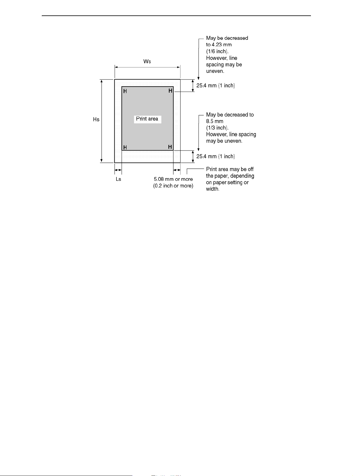
Printer and Paper Specifications
Print Area for Single Sheets
Ws 102 to 267 mm (4 to 10.5 in)
Hs 76 to 364 mm (3 to 14.3 in)
Ls 5.08 to 32 mm (0.2 to 1.26 in)
B-8
Page 93

Printer and Paper Specifications
Paper Thickness
Paper thickness is given by the weight of the paper in either grams per square meter (g/
m2) or in pounds per bond (lbs/bond). The following table shows the allowable paper
thickness for one-part paper or for each sheet of multipart paper. The total thickness must
not exceed 0.35 mm (0.014 inch).
The weight of carbonless or carbon-backed paper may vary, depending on the paper
manufacturer. When using paper of borderline thickness, test the paper before running a
job.
Type of Paper Number of Parts Thickness
One-Part Carbonless Single
Two-Part Carbonless Top
Bottom
Three-Part Carbonless Top
Middle
Bottom
Four-Part Carbonless Top
Middle
Middle
Bottom
Two-Part Carbon-Backed Top
Bottom
Three-Part Carbon-Backed Top
47–81 g/m
40–64 g/m
40–81 g/m
40–64 g/m
40–64 g/m
40–81 g/m
40–64 g/m
40–64 g/m
40–64 g/m
40–81 g/m
40–64 g/m
40–81 g/m
40–64 g/m
2
(12–22 lbs/bond)
2
(11–17 lbs/bond)
2
(11–22 lbs/bond)
2
(11–17 lbs/bond)
2
(11–17 lbs/bond)
2
(11–22 lbs/bond)
2
(11–17 lbs/bond)
2
(11–17 lbs/bond)
2
(11–17 lbs/bond)
2
(11–22 lbs/bond)
2
(11–17 lbs/bond)
2
(11–22 lbs/bond)
2
(11–17 lbs/bond)
Middle
Bottom
Four-Part Carbon-Backed Top
Middle
Middle
Bottom
40–64 g/m
40–81 g/m
40–64 g/m
40–64 g/m
40–64 g/m
40–81 g/m
2
(11–17 lbs/bond)
2
(11–22 lbs/bond)
2
(11–17 lbs/bond)
2
(11–17 lbs/bond)
2
(11–17 lbs/bond)
2
(11–22 lbs/bond)
Carbon-backed: Do not use in high humidity environments.
Carbon-interleaved: Avoid using single sheets format in carbon-interleaved.
B-9
Page 94

Printer and Paper Specifications
Type of Paper Number of Parts Thickness
Two-Part Carbon-Interleaved Top
Carbon Counted as one sheet
Bottom
Three-Part Carbon-Backed Top
Carbon Counted as one sheet
Middle
Carbon Counted as one sheet
Bottom
40–64 g/m
40–81 g/m
40–64 g/m
40–64 g/m
40–81 g/m
2
(11–17 lbs/bond)
2
(11–22 lbs/bond)
2
(11–17 lbs/bond)
2
(11–17 lbs/bond)
2
(11–22 lbs/bond)
B-10
Page 95

Command Sets
This appendix describes printer commands and their parameters.
This printer has the following two resident command sets (Emulations):
• IBM Proprinter XL24E (2390+)
• Epson-EP2
Select the same Emulation on the printer and in your software.
C
C-1
Page 96

Command Sets
IBM 2390+ Emulation Quick Reference Guide
This section describes the printer commands for the IBM 2390+ Emulation. Asterisks in the
“Function” column indicate extended commands that are not supported by the original printer.
Function Command
Print Mode Control
Double-strike (bold) printing on ESC G
Double-strike (bold) printing off ESC H
Emphasized (shaded) printing on ESC E
Emphasized (shaded) printing off ESC F
Single-line double-width characters on SO or ESC SO
Single-line double-width characters off DC4
Double-width characters on/off ESC W (n)
(on: n = 1, off: n = 0)
Double-height/double-width characters ESC [ @ (n1) (n2) (m1) ... (m4)
n1 = 4, n2 = 0, m1 = 0, m2 = 0
m3 controls character height and line spacing:
m
0 Unchanged Unchanged
1 Normal Unchanged
2 Double Unchanged
16 Unchanged Single
17 Normal Single
18 Double Single
32 Unchanged Double
33 Normal Double
34 Double Double
m4 controls character width:
m4 Width
0 Unchanged
1 Normal
2 Double
Condensed characters on SI or ESC SI
Subscript or superscript printing on ESC S (n)
(subscript: n = 1, superscript: n = 0)
Subscript and superscript printing off ESC T
Underline on/off (on: n = 1, off: n = 0) ESC - (n)
Overline on/off (on: n = 1, off: n = 0) ESC (n)
Height Spacing
3
C-2
Page 97

Function Command
Score select ESC [ - (n1) (n2) (m1) (m2)
n1 = 2, n2 = 0
m1 selects score location:
Command Sets
m
0 Underscore
1 Strikethrough
2 Overscore
1
Score location
m2 selects score type:
m2 Score type
0 Cancel
1 Single
2 Double
C-3
Page 98

Command Sets
Function Command
Horizontal Control
Space SP
Backspace BS
Carriage return CR
Select 10cpi DC2 :
Elite characters on ESC :
Proportionally spaced characters on/off ESC P (n)
(on: n = 1, off: n = 0)
Vertical Control
Line feed LF
Form feed FF
Advance paper n/216 inch (1 ≤ n ≤ 255) ESC J (n)
Advance paper n/180 inch (in AG mode) ESC J (n)
(1 ≤ n ≤ 255)
Set line spacing to 1/8 lines ESC 0
Set line spacing to 7/72 inch ESC 1
Set line spacing to n/216 inch ESC 3 (n)
(0 ≤ n ≤ 255)
Set line spacing to n/180 inch (in AG mode) ESC 3 (n)
(0 ≤ n ≤ 255)
Preset line spacing to n/72 inch ESC A (n)
(1 ≤ n ≤ 255)
Preset line spacing to n/60 inch (in AG mode) ESC A (n)
(1 ≤ n ≤ 255)
Set line spacing to 1/6 inch or to the value ESC 2
preset by line spacing command ESC A (n)
Change graphics line spacing base to ESC [ \ (m1) (m2) (t1) ... (t4)
1/216 or 1/180 inch (for ESC J and ESC 3)
m1 = 4, m2 = 0
0 ≤ t1 ≤ 255, 0 ≤ t2 ≤ 255, t3 = 0
t4 = 180 or 216
Reverse line feed ESC ]
Tabulation
Horizontal tab execution HT
Set horizontal tabs ESC D (n1) ... (nk) NUL
The values of n1to nk in this command are the
ASCII values of the print columns (at the current character
width) at which tabs are to be set.
(1 ≤ n ≤ 255) (1 ≤ k ≤ 28)
Clear all horizontal tabs ESC D NUL
Move print position right by n/120 inch ESC d (n1) (n2)
(0 ≤ n1, n2 ≤ 255) (n = n1 + n2 X 256)
C-4
Page 99

Command Sets
Function Command
Vertical tab execution VT
Set vertical tabs ESC B (n1) ... (nk) NUL
The values of n1to nk in this command are the ASCII values of
the lines (at the current line spacing) at which tabs are to be
set.
(1 ≤ n ≤ 255) (1 ≤ k ≤ 64)
Clear all vertical tabs ESC B NUL
Reset tabs to default values ESC R
Page Formatting
Set left margin at column n and right ESC X (n) (m)
margin at column m (0 ≤ n, m ≤ 255)
Set perforation skip by n lines ESC N (n)
(1 ≤ n ≤ 255)
Perforation skip off ESC O
Set page length to n lines (1 ≤ n ≤ 255) ESC C (n)
Set page length to n inches (1 ≤ n ≤ 22) ESC C NUL (n)
Set top of form ESC 4
Character Set Control
Select character set 1 ESC 7
Select character set 2 ESC 6
Print n1 + n2 X 256 characters from all-character set ESC \ (n1) (n2) (chars.)
(chars.: codes of characters to print,
0 ≤ chars. ≤ 255)
Print a character from all-character set ESC ^ (char.)
(char.: a code of character to print,
0 ≤ char. ≤ 255)
C-5
Page 100

Command Sets
Function Command
Select code page table ESC [ T (n1) (n2) 0 0 (c1) (c2)
(0 ≤ n1, n2 ≤ 255) (n = n1 + n2 X 256)
c1, c2: Decimal (n1 = 4, n2 = 0)
c1 c2 Code page ID
0 0 Ignore command
1 181 Code page 437
3 82 Code page 850
3 83 Code page 851
3 84 Code page 852
3 87 Code page 855
3 89 Code page 857
3 90 Code page 858**
3 92 Code page 860
3 94 Code page 862
3 95 Code page 863
3 96 Code page 864
3 97 Code page 865
3 98 Code page 866
3 101 Code page 869
3 152 Code page 920
3 155 Code page 923**
40 197 Code page 437G
42 101 Code page 853
42 114 Code page USSR GOST
**Code page contains Euro currency symbol
Clear input buffer CAN
Select printer DC1
Deselect printer (ignore input) ESC Q #
ESC Q $
C-6
 Loading...