

Page 1

User guide LA48N LA48W Matrix printer
Page 2

TRADEMARK ACKNOWLEDGEMENTS
• Centronics is a trademark of Centronics Data Computer Corporation.
• IBM and IBM PC are trademarks of International Business Machines Corporation.
• Microsoft, Windows, Windows 95, Windows 98, Windows ME, Windows 2000, Windows 2003 Server, Windows XP
and Windows Vista are registered trademarks of Microsoft Corporation.
• PostScript is a trademark of Adobe Systems Inc.
• DEC is a trademark of Digital Equipment Corporation
• Epson is a registered trademark of Seiko Epson Corporation
• All other brand or product names are trademarks of their respective companies or organizations.
Page 3

Table of contents
Table of contents
Introduction 1-1
1
Features 1-1
Consumables 1-2
2 Setting up the printer 2-1
Selecting a location 2-1
Unpacking the printer 2-2
Assembling the printer 2-4
Installing the Cut Sheet Stand 2-4
Installing the Ribbon Cartridge 2-5
Getting acquainted with your printer 2-8
Connecting the power cord 2-9
Connecting the printer to your computer 2-11
Selecting a Parallel Interface Cable 2-11
Selecting a Serial Interface Cable 2-11
Selecting a USB Cable 2-12
Connecting the Interface Cable 2-12
Removing the shutter 2-14
Attaching the shutter 2-14
Selecting an emulation 2-15
Operations of the control panel 2-18
Control panel indicators and buttons 2-18
Basic states of the printer 2-18
Control Panel Operations 2-20
Printer Acoustical Feedbacks 2-22
I
Page 4

Table of contents
3 Paper Handling 3-1
Selecting Paper 3-2
Paper Specifications 3-2
Paper Size 3-2
Paper Thickness and Number of Copies 3-2
Overview of Paper Operations 3-3
Levers and Buttons Used for Paper Handling 3-4
Adjusting for Paper Thickness 3-6
Paper Thickness Lever Positions 3-7
Using Single Sheets 3-8
Loading a Single Sheet of Paper 3-8
Ejecting Single Sheets 3-10
Using Continuous Forms 3-11
Positioning the Paper Stack 3-11
Good placement 3-11
Bad placement 3-11
Loading Continuous Forms 3-12
Adjusting the left margin 3-13
Adjusting the Tear-off position 3-15
Adjustment procedure 3-15
Unloading Continuous Forms 3-16
Installing the Tractor Unit 3-16
Tearing Off Continuous Forms 3-17
Feeding and Positioning Paper 3-18
Print Area Definition 3-18
Line Feed/Form Feed 3-20
Top-of-Form Adjustment 3-20
Switching Paper Types 3-22
Switching from Continuous Forms to Single Sheets
(Push-Feed Mode) 3-22
II
Page 5

Table of contents
Switching from Single Sheets to Continuous Forms
(Push-Feed Mode) 3-22
Tips on Paper Handling 3-23
General Tips 3-23
Multipart Forms 3-23
Envelopes 3-23
Labels 3-23
4 Printing 4-1
Selecting Print Features 4-1
Using Commercial Software 4-1
Using the Control Panel 4-2
Macrol selection 4-2
Macro 1 and Macro 2 Settings 4-3
Installation Settings 4-5
Adjustments Settings 4-5
Menu Access Settings 4-5
Changing the Protocol 4-6
Starting or Stopping Printing 4-8
Starting Printing 4-8
Stopping and Viewing Printing 4-8
Resuming Printing 4-8
Resuming from a Paper-Out 4-8
Removing Printed Pages 4-10
Removing Single Sheets 4-10
Removing Continuous Forms 4-10
5 Using Set-Up Mode 5-1
What is Set-Up Mode for? 5-1
How Set-Up Works 5-2
Entering the Set-Up Mode 5-2
III
Page 6

Table of contents
Overview of the Set-Up Mode 5-4
Set-Up Mode Functions 5-4
Example: Changing the Vertical Pitch 5-5
Options with Undetermined Values 5-7
Range Management for a Wide Range of
Values 5-7
Example: Changing the Left Margin 5-7
Options with Both Pre-determined and
Undetermined Values 5-8
Points to Remember 5-11
Printing the Printer Configuration 5-12
Deciding Which Options to Change 5-14
Required Options 5-14
Changing Macro 1 and Macro 2 Options 5-15
Macro 1 and Macro 2 Options and
Values 5-16
Changing Install Options 5-25
Install Options and Values 5-26
Adjusting Top-of-Form Origin 5-30
Adjust Options and Values 5-30
Changing Menu Access Options 5-31
Menu Access Option and Values 5-32
Save Settings and Exit Set-up mode 5-33
Recall Factory Settings 5-33
Using the Diagnostic Functions 5-34
Printing Test 5-34
Hex Dump Mode 5-35
Set-Up Mode Quick Reference 5-37
6 Maintenance 6-1
Cleaning 6-1
Cleaning and Vacuuming the Printer 6-1
Cleaning the Platen 6-2
IV
Page 7

Table of contents
Replacing the ribbon 6-3
Replacing the Print Head 6-7
7 Trouble-Shooting 7-1
Solving Problems 7-1
Print Quality Problems 7-1
Paper Handling Problems and Solutions 7-4
Operating Problems and Solutions 7-6
Printer Failures 7-7
Diagnostic Functions 7-8
Checking Vertical Alignment 7-8
A Supplies A-1
Supplies A-1
B Printer and Paper Specifications B-1
Physical Specifications B-1
Functional Specifications B-2
Performance Specifications B-4
Certification B-4
Paper Specifications B-5
Print Area B-5
Paper Thickness B-7
V
Page 8

Table of contents
C Command Sets C-1
DEC PPL2 Quick Reference Guide C-2
IBM Proprinter X24E and XL24E Quick Reference
Guide C-22
Epson ESC/P2 Quick Reference Guide C-27
D Interface Information D-1
Parallel Interface D-1
Serial Interface D-4
USB Interface D-7
E Character Sets E-1
DEC PPL2 Protocol E-1
Common to IBM Proprinter X24 and XL24E Protocol
and EpsonESC/P2 Protocol E-19
IBM Proprinter X24E and XL24E Protocol E-25
Epson ESC/P2 Protocol E-26
F Resident Fonts F-1
VI
Page 9
Introduction
1
Introduction
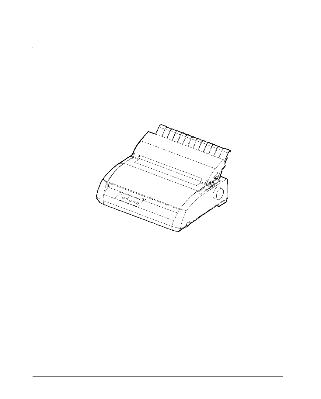
Congratulations on purchasing a LA48N/LA48W printer. This printer is a compact,
versatile printer that offers maximum compatibility with today’s software packages
and personal computers. The 24-wire print head provides crisp, clear printing for
business, office, and home environments. This printer is also easy to install and use.
Features
Key printer features and options are listed in the next two sections.
Software compatibility. This printer operates with the DEC PPL2, IBM XL24E,
Various character sets. For the DEC PPL2 protocol, 31 character sets (twenty-
Multiple fonts. The printer has 12 resident fonts: Draft, High speed Draft, High
Matrix Printer LA48N
and EPSON ESC/P2 command sets.
five 94-character sets and six 96-character sets) are available. For IBM Proprinter
X24E and XL24E protocol, set 1, set 2, and 30 default sets (code pages and specific character sets) are available. For Epson ESC/P2 protocol, 15 national character sets and 30 default sets (code pages and specific character sets) are available.
impact Font, Courier 10, Pica 10, Prestige 12, Compressed, Boldface PS, Timeless Normal, Nimbus Sans Normal, OCR-A, OCR-B.
1-1
Page 10

Introduction
High-speed printing. At 10 cpi, print speed ranges from 113 cps for letter quality
to 400 cps (80-column printer) or 448cps (136-column printer) for high-speed
draft quality.
Large print buffer. 64 Kbytes are available in total for storing input data and
downloading fonts. A large input data buffer allows you to send files to the printer and return quickly to work in your application. A large download buffer allows
you to use custom fonts.
80-column or 136-column print line. 80-column printers are the most suitable
for printing in landscape mode using letter or A4 size paper.136-column printers
are the most suitable for printing in landscpe mode using legal or standardsize
computer forms.
Simple switching of paper types. The ability to "park" continuous forms makes
it easy to switch between continuous forms and single sheets.
Auto tear-off. Continuous forms are fed automatically up to the tear-off position
at the end of each job.
Maintenance-free. The printer only requires periodic cleaning and changing of
the ribbon cartridge.
Consumables
For details, see Appendix A, “Supplies”.
1-2
Page 11

Setting up the printer
2
Setting up the printer
Your new printer is easy to install and set up. This chapter tells you how to set up the
printerand start printing right away. If this is your first printer, you should read the
entire chapter before attempting to use the printer. In this chapter, you will learn how
to:
Unpack, assemble, and select a good location for the printer
Identify the printer’s major parts
Connect the power cord and the interface cable
Test the printer before connecting it to your computer
Select an emulation and print a sample page using your software
If you have a problem while setting up the printer, review the section “Solving Problems” in Chapter 7. If the problem persists, contact your dealer or service.
Selecting a location
This printer is suitable for most business, office, and home environments. To obtain
peak performance from the printer, select a location that meets the following guidelines:
3 Place the printer on a sturdy, level surface.
3 Place the printer near a well-grounded AC power outlet.
3 Ensure easy access to the front and rear of the printer by leaving several inches of
space around the printer. Do not block the air vents on the front, left, and right sides
of the printer.
3 Do not place the printer in direct sunlight or near heaters.
3 Make sure that the room is well-ventilated and free from excessive dust.
3 Do not expose the printer to extremes of temperature and humidity.
3 Use only the power cord supplied with the printer or recommended by your dealer.
Do not use an extension cord.
3 Do not plug the printer into a power outlet that is shared with heavy industrial equip-
ment, such as motors, or appliances, such as copiers or coffee makers. Such equipment often emits electrical noise or causes power degradation.
2-1
Page 12
Setting up the printer
Unpacking the printer
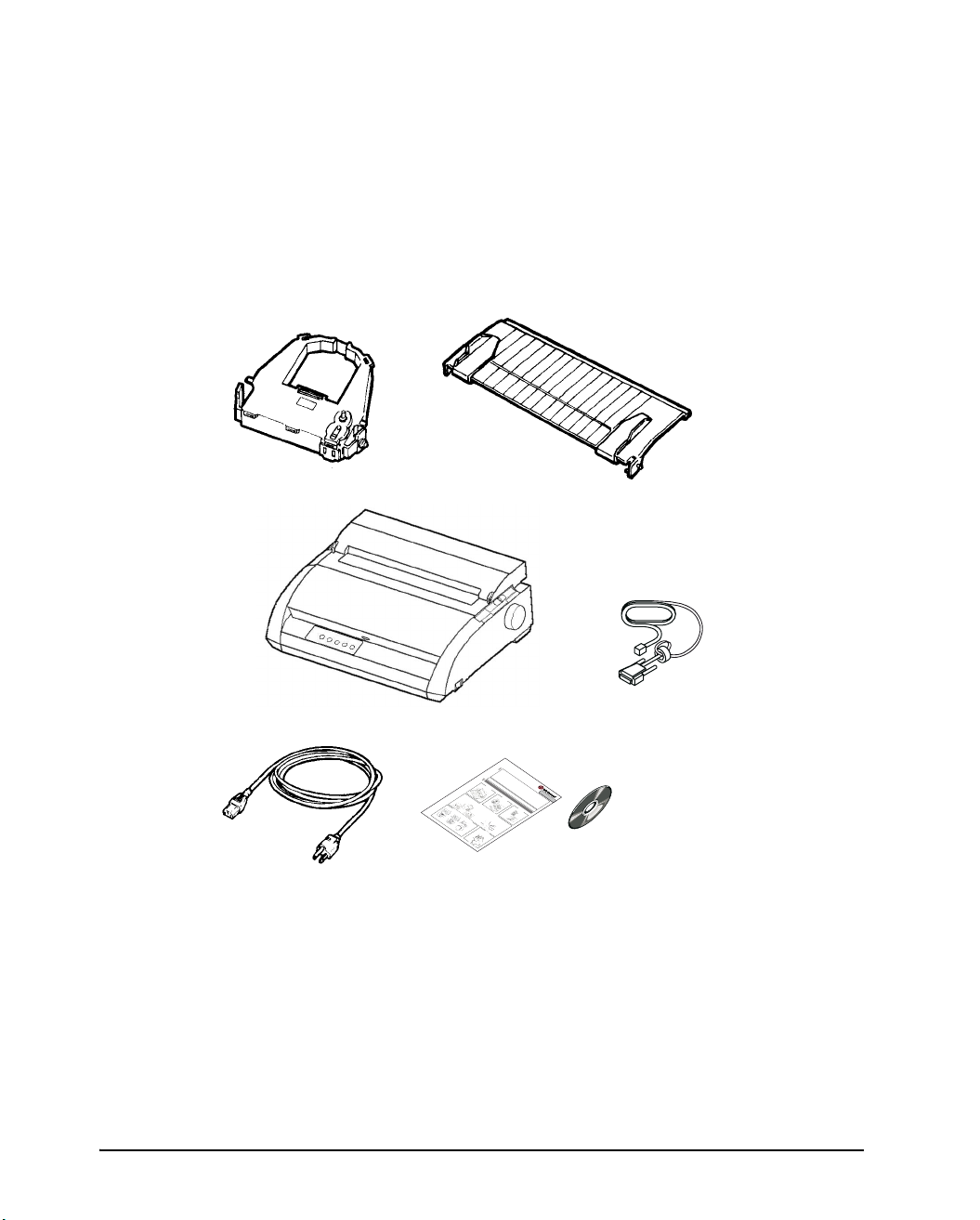
Unpack the printer as follows:
1. Open the carton and remove the printer and its components. Make sure that you
have all of the items shown below. Note that the power cord supplied depends
on the printer model (100-120 or 220-240 VAC power supply).
Ribbon cartridge
(Black)
Power cord
Cut sheet stand
Printer
Quick Start Guide
and CD-ROM
Quick Star
t G
Saf
For d
et
ship
uid
yGuid
Ke
e
tai
pe
ep thisU
led in
dw
!
P
e
eli
!
i
th
K
fo
! Veri
nes
e
your p
r
e
serG
m
p
htecal
ation, refer to t
e
a
!Protect t
rp
fy th
ni
p
rinter
u
t
lll
i
ir
ide
q
n
e pr
et
ire
n
diu
r
i
. Be sure
n
ot
o
op
a
n
h
P
ht
pl
er sourc
eprin
a
e
leaseconfirmtha
ac
he U
Blac
yawas
os
aw
f
e
l
te
di
to
w
ser Guide
sll
kribb
rfr
re
e volt
hich
us
co
r
Sett
om
htmor
a
k
e
d the
is
p
age
o
ecaf
.te
s
.
n
hock, im
easi
nir
Opent
safet
o
car
et
be
ing u
f
r
ly
.
t
for
t
he
tridg
the
accessible at all ti
y gu
e pl
pa
h
print
O
ecar
e
ct
foll
idelines in the
ugg
pen
p
theshipping
(1),
er.
a
o
nd vib
in
to
wi
the
gth
Powercor
nandremovetheprint
n
gthi
Cardbo
r
frontcoveran
e
ati
o
ng
1-1
n.
r
ard
s
est
d(1),M
areenclosedi
rai
nt
dr
car
M
emove
J
dboar
interfac
e
Fron
r
n
a
d.
th
ndi
t
p
eshipp
cove
e
t
adap
scom
r
ing
ter(1)
Releas
pone
Ins
Inthegray
car
rol
tall
,
nts.
ton
CD-ROM
ethe
le
Mountin
in
:
rfrom
R
g
Pri
emov
thecutshee
ribboncartridg
nte
r
1-2
i
bbon
g pins
th
r
(1),
eth
eLOC
thi
r
e
el
tape
eas
tsta
K
positio
e
efrom
s
Rol
nd.
tabson
sec
le
r
C
Releas
tab
s
e
1-5
Conn
C
e
n
tro
n
ic
s p
a
ra
l
lel
C
e
n
tron
ics
p
a
ra
l
lel +
R
S
-2
3
2
C
C
entron
ic
s
p
a
ra
llel +
uri
n
ut
it
ngt
t
spack
o
she
1-4
th
the
esi
h
et stand
etractorunit.
F
Insta
ag
de,a
RE
ean
Mov
E
n
posi
dslid
d
lling the Ri
e
push
thepaperthic
tion
e
the
Ribb
.
o
Tur
n
fee
A
bbon
n
l
ignthe
the
pr
d knob
i
he
n
knob
t
e
car
ad
ect
Cartr
re
pri
(Mak
tridge
an
j
clo
ecti
ing
nthea
d
ckwis
idge
on
esur
t
hepri
the
against
cover.Thr
d
e
e
posi
int
Pap
ntguide,
tha
t
theprinteruntil
e
io
erfac
tth
rthi
n
eribbo
ea
wit
ckne
t
d
ht
he
e
Print
th
Ribbon
ss l
hedo
nge
cable
R
e
P
n
ib
head
rin
P
r
ever
b
feedknob
ibb
rin
o
tg
nt
cartridge
n
t
t
u
l
h
o
c
i
y
mar
t
id
artr
e
n
a
clicksinto
e
pres
d
b
i
d
e
k
g
t
e
(gree
wee
sdo
i
s
faci
n
wno
n
t
plac
)
h
n
on
ep
gu
D
nt
ot
e.
the
rin
pwar
m
heribb
ar
Dot
t
k(g
R
i
d.)
mark (gree
b
r
Rib
e
b
en
o
on
P
n
)
bon
rin
tg
T
u
i
p
id
n)
Pl
o
e
Print
f
u
cor
p
g
rin
on
on
guid
Tip of pr
di
t
h
eendo
e
nt
therea
a
e
d
ot
U
1-6
int
SB
h
e
hea
ro
f
powe
thepower
d
fthe
r
Pow
connector
pri
e
n
rco
ter
.
rd
N
379839a-E
MMJ Interface adapter
The User Guid
mes.
Use
r
Gu
e i
s provid
i
de b
efore us
ed as
oD!
s
not
! Kee
u
LA48N / LA48W
n
l
an
in
i
g
e
g
xp
p t
Adobe
this prod
th
pa
.
ose t
he p
ere
d
owe
h
g
Acroba
e p
uct
r cord
rinter to h
orfe
.
m
tPDF fi
d
cle
a
m
a
a
igh temp
g
r of the
le
ni
g
o
n the
(1)
pap
era
peht
CD
o
,
tur
e
Cu
r
ew
s
pa
es
t
Quick
cr
shee
o
th to
or dire
r
d
s
a
tstan
ni
Start
v
ct
oid the
us
l
ta
d(1),
Guid
oi
.n
e(1)
13
knes
s
lev
er
to
D.
2-2
Checking items received
2. Carefully examine each item for damage. Report any problems to your dealer or
shipping agent.
3. Place the printer where you plan to use it.
4. Remove the tapes securing the front cover, ejection cover, and back cover. Open
the front cover and remove the shipping restraint cardboard that holds the print
Page 13
Setting up the printer
head carriage in place (shown below).
Front cover
Cardboard
Removing the shipping restraint cardboard
5. Store the original shipping carton and packaging materials for future use. For
example, the original packaging is ideal for use when you move or ship your
printer to another location.
NOTE: The interface cable is not included with the printer. You must purchase it
separately. Connection of the interface cable is described later in this chapter.
2-3
Page 14
Setting up the printer
Assembling the printer
This section explains how to install the cut sheet stand and ribbon cartridge.
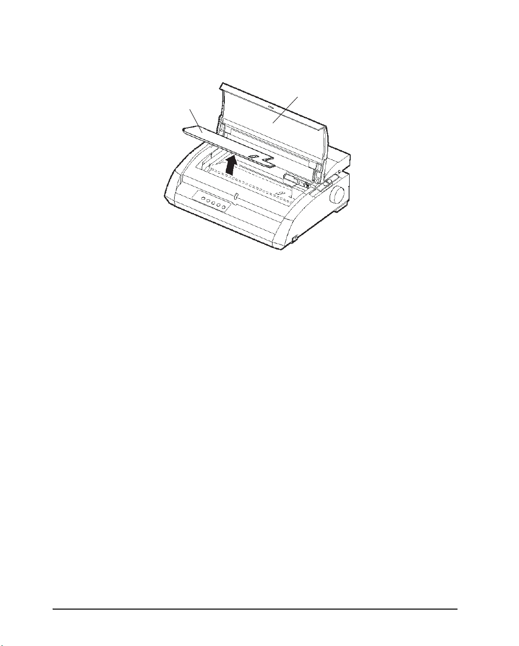
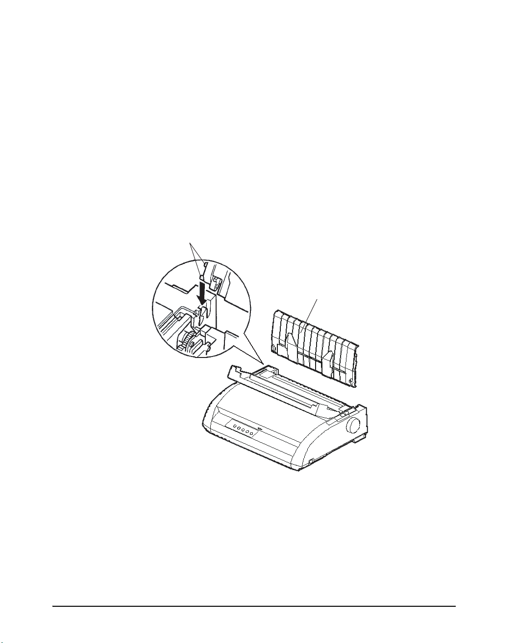
Installing the Cut Sheet Stand
The cut sheet stand enables smooth feeding of both single sheets and continu-ous
forms. Install the cut sheet stand as described below:
1. Referring to the following figure, locate the two grooved notches on the top of
the printer, behind the top cover. Note that each notch has a front groove and a
rear groove.
2. Locate the two mounting pins on each side of the cut sheet stand.
Mounting pins
Cut sheet stand
2-4
Installing the cut sheet stand
3. Hold the cut sheet stand at an angle over the top of the printer. Slide the mount-
ing pins into the long, front grooves of the notches. This is the cut sheet stand's
up position, used for printing single sheets.
To rotate the cut sheet stand to its down position, grasp it at the sides and lift it up
until the two upper mounting pins clear the front notches. Rotate the cut sheet
stand backward to place the upper mounting pins in the rear grooves.
Page 15
Setting up the printer
r
Installing the Ribbon Cartridge
The printer uses a black ribbon cartridge. To install the ribbon cartridge:
1. Turn the printer off. Open the front cover of the printer. For easy installation,
slide the print head carriage to the middle.
2. The paper thickness lever, located on the right of the printer, has nine positions.
Before you install the ribbon cartridge, move this lever to D.
Paper thickness leve
Move to D.
Preparing to install the ribbon
2-5
Page 16
Setting up the printer
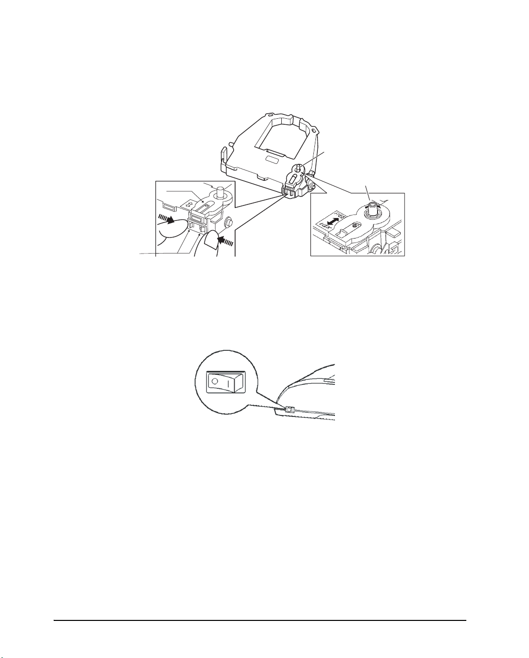
3. Using the procedure below, release the roller from the LOCK position and turn
the ribbon feed knob clockwise to take up any ribbon slack. Push in the gray ribbon release tabs on the side of the ribbon cartridge to release them, and slide the
roller from the LOCK position to the FREE position.
Release tabs
CAUTION:Do not turn the ribbon feed knob in counterclockwise direction.
Ribbon feed knob
Turn the knob clockwise
Roller
Preparing the ribbon cartridge
4. Verify that the power to the printer is off (make sure that the circle mark on the
power switch is pressed).
Verify that the printer is switched off
5. Move the paper thickness lever to the D position.
6. Open the front cover.
2-6
Page 17
Setting up the printer
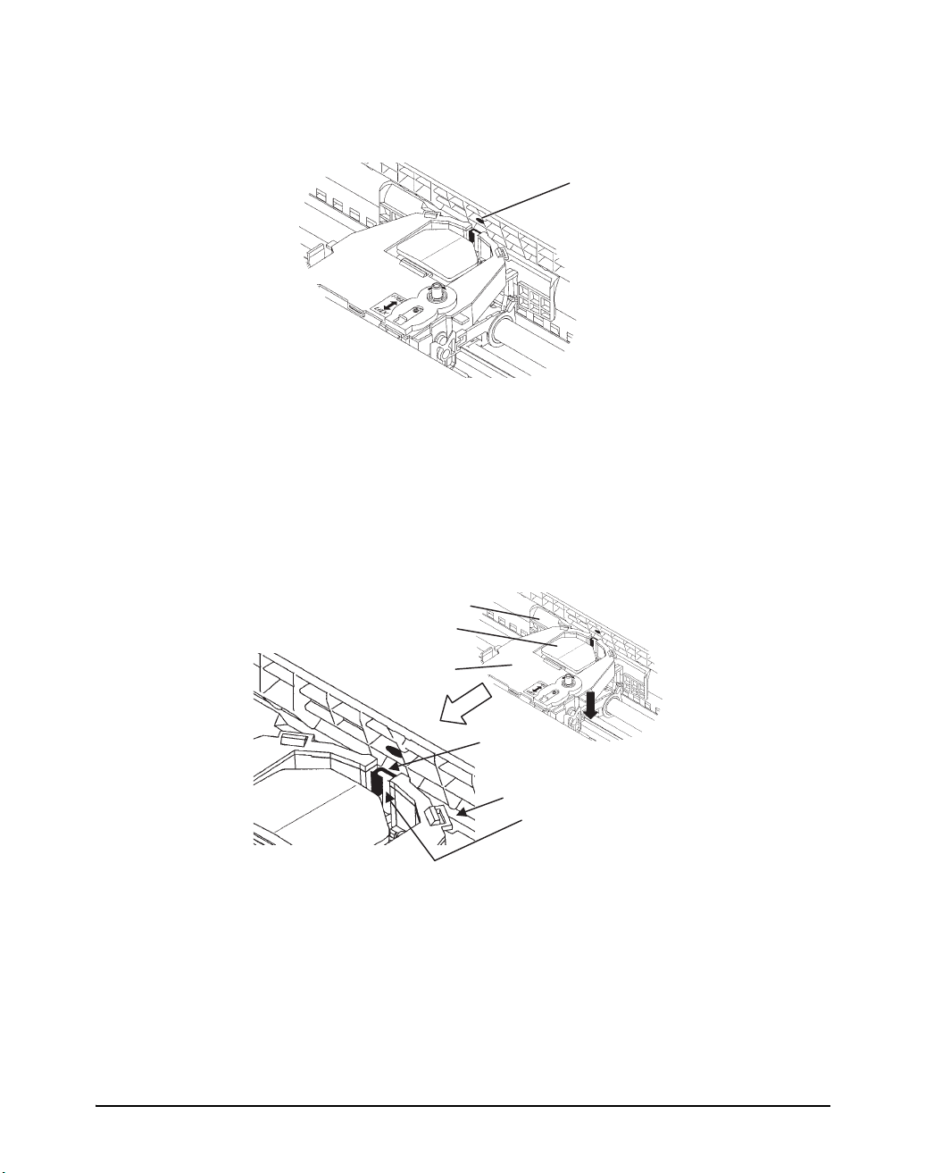
7. Align the print head position with the dot mark (green) on the printer ejection
cover.
Dot mark (green)
WARNING: Avoid touching the print head while using or immediately after using
the printer, as doing so may lead to burns. Wait until the print head
cools down before touching it.
8. Thread the ribbon between the print head and the print guide, then gently press
down on the ribbon cartridge against the printer until it clicks into place.
(Make sure that the ribbon feed knob is facing upward.)
Print guide
Print head
Ribbon cartridge
Ribbon
Print guide
Tip of print head
9. Turn the ribbon feed knob clockwise to take up any ribbon slack.
10.After the ribbon cartridge has been installed in the printer, adjust the paper thick-
ness lever to match the thickness of the paper and the number of sheets of paper
to be used.
For information about the paper thickness lever, see the section entitled “Adjusting for Paper Thickness” in Chapter 3.
2-7
Page 18
Setting up the printer
Getting acquainted with your printer
Now that your printer is assembled, take a moment to become familiar with its major
parts.
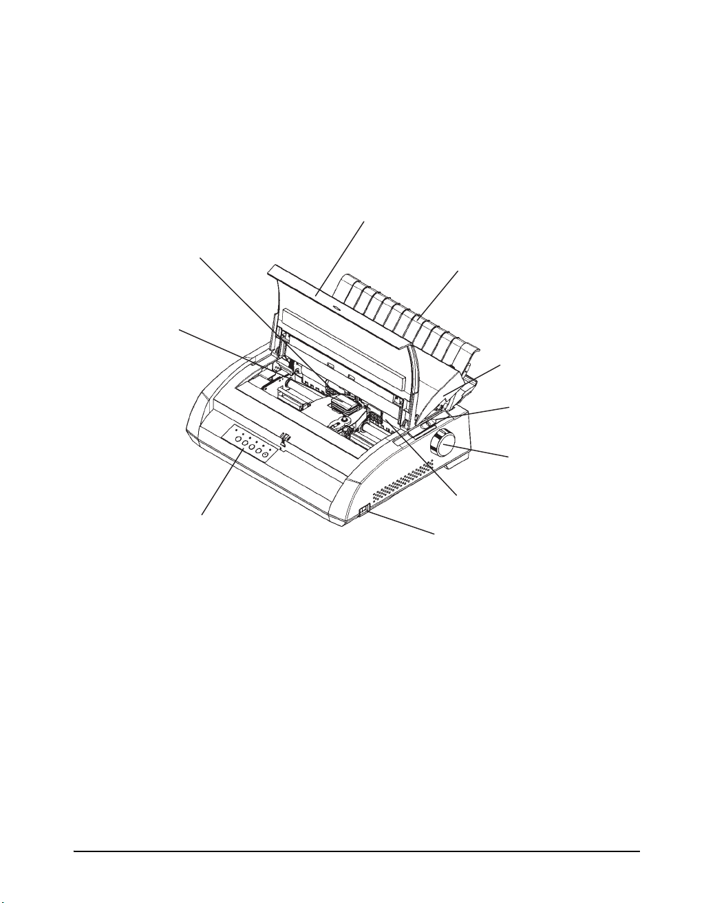
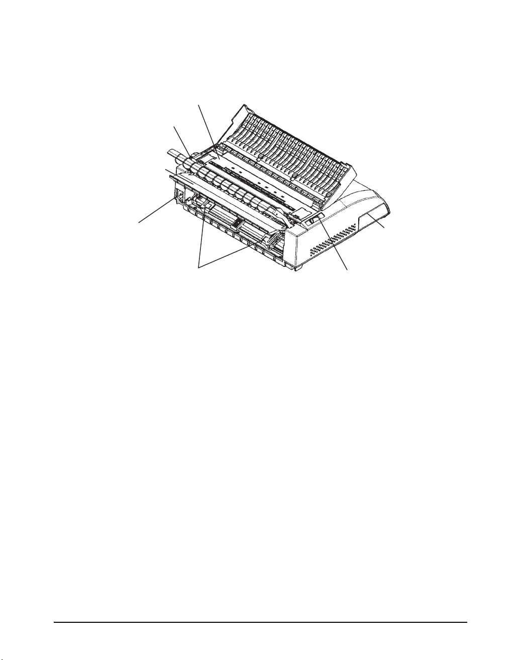
Looking at the printer from the front right side, you can see the parts of the printer
shown in the figure below.
Front cover
Print guide
Print head
Cut sheet stand
Acoustic cover
Paper thickness lever
Platen knob
Platen
Control panel
Printer components (front and right)
Powerswitch
The printer control panel has the buttons and indicators used to load and feed paper
(see Chapter 3, “Paper Handling”) and select print features (see Chapter 4, “Printing”). The control panel also allows you to change the printer’s optional settings (see
Chapter 5, “Using Set-Up Mode”).
2-8
Page 19
Setting up the printer
r
Looking at the printer from the back with the cut sheet stand and back cover removed, you can see the following parts of the printer:
Ejection cover
Paper guide
Back cover
Power
connector
Forms tractors
Printer components (rear)
Paper select lever
Interface
connecto
Connecting the power cord
Before you plug in the printer:
3 Make sure that the printer power is switched off. The side marked “1” on the power
switch should be raised.
3 Make sure that the power outlet is properly grounded.
3 Make sure that you use the power cord shipped with the printer. This cord is de-
signed to minimize radio frequency interference.
To plug in the power cord:
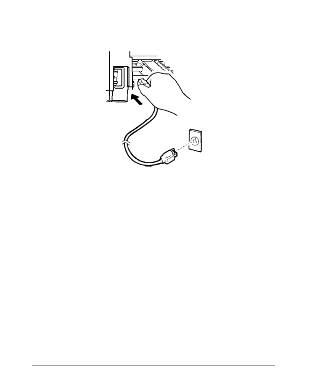
1. Plug one end of the power cord into the power connector on the rear of the
printer.
2-9
Page 20
Setting up the printer
2. Plug the other end of the power cord into the power outlet.
Connecting the power cord
3. Make sure that the power cord is securely connected.
4. Turn on the power by pressing the side marked “I” on the power switch. Within
a few seconds, the POWER indicator on the printer control panel will light, the
print head will move to its home position, and the ONLINE indicator will light
(green).
NOTE: If no forms are loaded, the printer may beep and the grenn FAULT indicator
may light and the ONLINE indicator will not light if the paper select lever is
set backward to the continuous forms position. Move the paper select lever
forward to the single sheet position (as described in the next section). The
FAULT indicator will go out. This condition is a result of the factory default
settings and poses no problem.
2-10
Page 21

Connecting the printer to your computer
Your printer supports one of the following interface options:
Centronics parallel interface only
Centronics parallel interface and RS-232C serial interface
Centronics parallel interface and USB interface
The RS-232 serial interface is a factory-installed option for a Centronics parallel interface model. Installation of the serial option provides a dual interface feature enabling the connection of either interface but inhibiting the operation of both
interfaces at the same time.
The parallel interface connector has wire clips. The serial interface connector has
tapped holes. Cables for these interfaces are available from dealers, cable manufacturers, and other suppliers.
The LAN adapter is a user installable option. For details, refer to the Manual that
comes with the LAN card.
NOTE: If a LAN interface card is installed, the Centronics parallel interface is not
available.
Setting up the printer
For detailed interface specifications, see Appendix D.
Selecting a Parallel Interface Cable
For the parallel interface, use a cable that meets the following specifications:
3 At the printer end, use a shielded male Centronics connector, such as an Amphenol
DDK 57FE-30360 or its equivalent. To prevent RFI (radio frequency interference),
the connector cover must be connected to the cable shield.
3 At the computer end, most computers (including IBM PCs) require a male DB-25P
connector. Some computers, however, require a Centronics connector. To determine the type of connector your computer uses, refer to your computer user manual.
3 Make sure that the cable length does not exceed 3 meters (10 feet).
Selecting a Serial Interface Cable
For the serial interface, use a cable that meets the following specifications:
3 At the printer end, use a 25-pin male connector, such as a Cannon DB-25P or its
equivalent.
3 To determine the type of connector your computer requires, refer to your computer
user manual or ask your dealer.
3 The cable length can be up to 15 meters (50 feet). This type of length is required in
many networking and shared-printer configurations.
2-11
Page 22
Setting up the printer
Selecting a USB Cable
3 When the USB interface is used to connect to the host computer, the parallel interface
and the serial interface (factory add-on option) cannot be connected simultaneously.
3 The USB interface does not guarantee all connections of USB-supported devices.
Connecting the Interface Cable
To connect the interface cable:
1. Turn off both the printer and the computer.
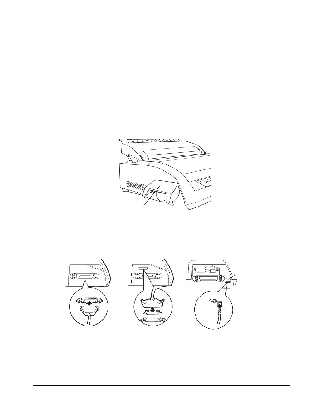
2. Pull the shutter on the left side of the printer upward as far as it will go.
Shutter
Opening the shutter
3. Attach the interface cable to the connector. Do not connect more than one inter-
face cable type to the printer at the same time.
Centronics parallel Centronics parallel + USBCentronics parallel + RS-232C
Connecting the interface cable
2-12
Page 23

Setting up the printer
4. To secure a parallel interface cable, flip the fastener clips located on the printer
into the notches on the cable connector. To secure a serial interface cable,
tighten the screws in the cable connector.
5. Attach the other end of the interface cable to your computer. Gently pull on the
cable to verify that it is secure.
6. Close the shutter.
NOTE: When use of the shutter is not required, remove it by using the following pro-
cedure.
2-13
Page 24
Setting up the printer
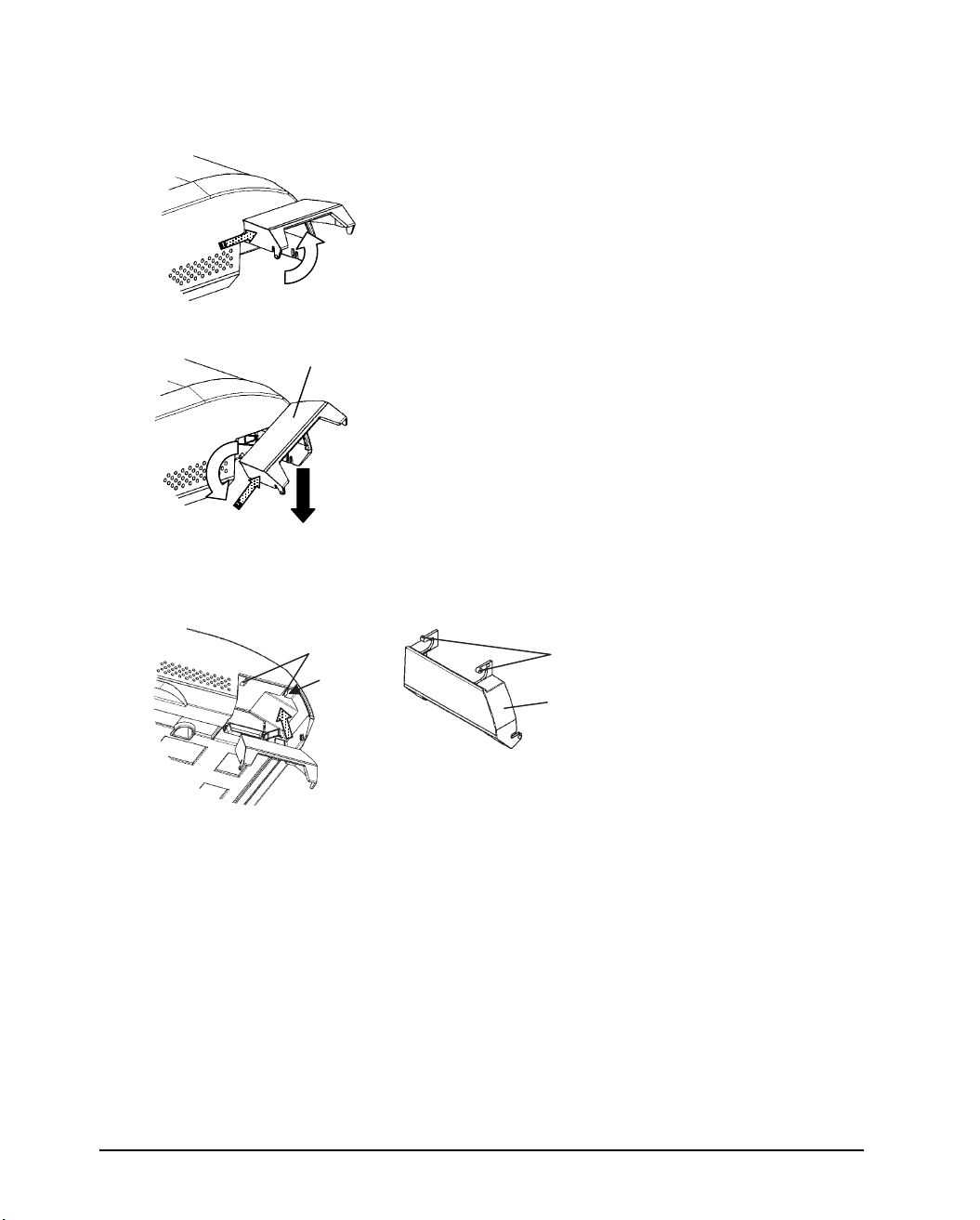
Removing the shutter
1. Open the shutter.
Shutter
Attaching the shutter
Mounting slots
(a)
2. Gently push the back end of the
shutter toward the front of the
printer.
3. While holding the shutter in the
position described in step 2, rotate
it in the manner shown in the
Ta bs
Shutter
2-14
5. Tilt the shutter and pass the shutter
tabs through the mounting slots,
starting with the slot on side (a)
shown in the figure on the left. The
order in which the shutter tabs are
CAUTION:Take care not to use excessive force when pushing the back of the shutter
toward the front of the printer. Otherwise, the shutter tabs may be damaged.
To reattach the shutter, tilt the shutter and insert one of its convex parts
into the installation hole of the printer, and then insert the other part in
the other hole. After inserting both convex parts, lower and push the
shutter in to its original position.
Page 25

Selecting an emulation
Before printing with your software, verify that the correct emulation is selected on
your printer. This section describes the available emulations and their selection.
An emulation is a set of commands used by your software to communicate with the
printer. There are many different emulations available for printers. Each emulation
has unique features and capabilities. This printer offers three resident emulations:
DEC PPL2
IBM Proprinter XL24E
EPSON ESC/P2
The printer’s preselected factory setting for the emulation settings is port dependant
(PORT DEPND), which means that for every interface a different emulation is set.
The default setting for the serial interface is DEC PPL2, for the parallel interface EPSON ESC/P2 and for the USB interface EPSON ESC/P2.
It is also the possibility to select an Autosening setting, which detects the correct emulation setting automatically.
Setting up the printer
Resident emulations are stored in the printer’s permanent memory.
Here are some points to help you determine which emulation to select:
3 Determine which emulations your software supports. (Refer to your software docu-
mentation.) Since most software programs support this printer, try to run a program
with the factory default emulation first. Try this emulation even if you are not sure
of which emulation to choose. See Chapter 5, “Using Set-Up Mode”, for detailed information about how your printer communicates with your software.
3 If you are using more than one software package, determine which emulation is sup-
ported by the software you use most frequently. Select that emulation.
3 If your software supports more than one emulation, select the DEC PPL2 emulation
if possible. This emulation has the greatest capabilities.
3 If you want to use an emulation that is not supported by your software, contact your
software manufacturer or printer dealer and ask whether support is available. You
may be able to obtain a printer driver that is not shipped with the original software
package.
2-15
Page 26
Setting up the printer
To select an emulation, proceed as follows:
1. Switch off the printer.
2. Make sure that paper is loaded (continuous paper or single form).
3. Remove the acoustic cover in order to see the printed text.
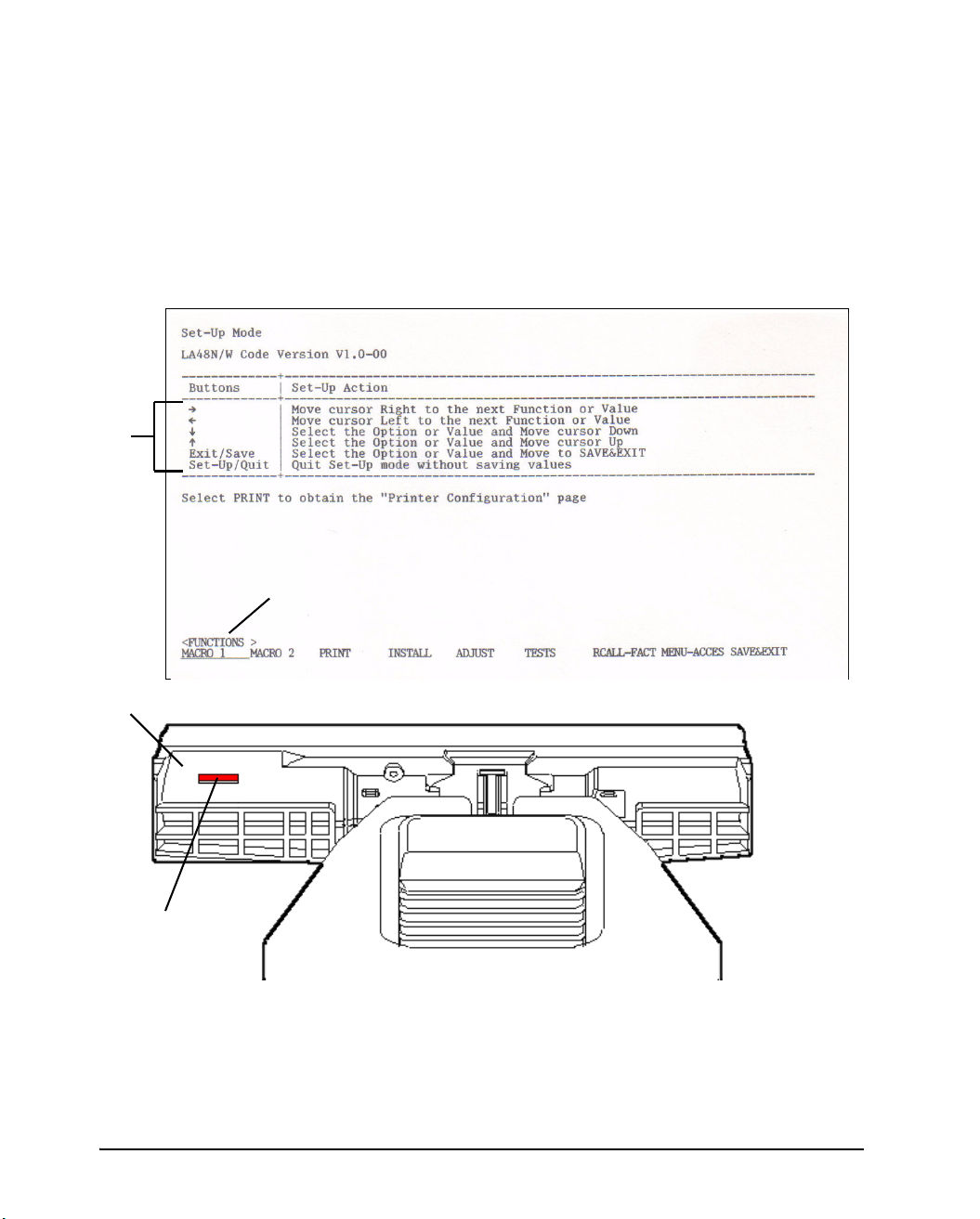
4. Hold the Setup/Quit buttons depressed and switch the printer on. After initializ-
ing the printer enters the setup mode and prints the following information:
1
2
4
MACRO 1
3
2-16
Page 27

Setting up the printer
The initial printout contains a header, help menu 1, and <FUNCTIONS> menu 2.
The header tells you that the printer is in the Set-Up mode. The help menu provides
a quick summary of how to use buttons in the Set-Up mode.
The <FUNCTIONS> menu
Generally speaking, the red cursor
2 lists all of the functions available in the Set-Up mode.
3 on the plastic print guide 4 indicates the function
or value to be selected. When entering the Set-Up mode, the red cursor is initially
positioned under MACRO 1.
5. Press the button to select the Macro 1 function and print the <PROTOCOL>
option and its values.
6. Repeatedly press the button or the button to position the red cursor on the
plastic print guide under the emulation you require.
7. Press the Exit/Save button to select the emulation and exit Set-Up mode.
2-17
Page 28
Setting up the printer
Operations of the control panel
This section summarizes status indications and operations of the control panel in
Normal mode. For details on Set-Up mode, see Chapter 5, “Using Set-Up Mode”.
Normal mode operation includes everyday operations, such as paper handling, macro
selection, and protocol selection. The first table lists basic states represented by the
Ready and Fault indicators. The second table lists Normal mode operations and required user response. Operations are listed by functions.
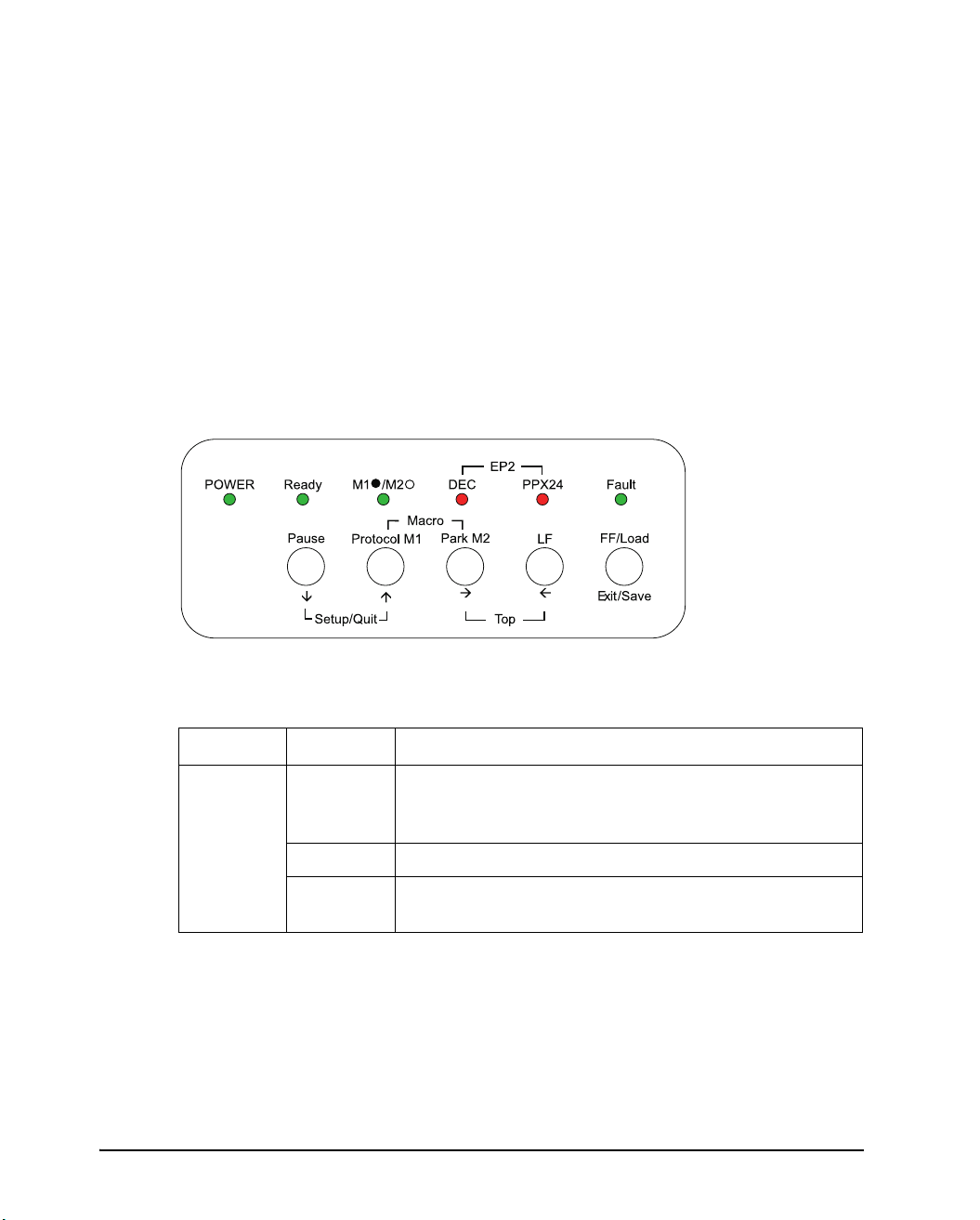
Control panel indicators and buttons
The control panel indicators display the state of the printer and the control panel buttons control the work with the printer.
Basic states of the printer
Indicator Status Printer status
Ready On The printer is ready for printing
Blinking The printer is not ready and holds printing data.
Off The printer is not ready and it does not hold printing
2-18
or
The printer is receiving or printing data.
data.
Page 29
Indicator Status Printer status
Fault On The printer is out of paper.
Setting up the printer
Blinking
fast
It is blinking at a 0.5 second period when paper jam,
carriage error, communication error, buffer overflow is
detected, or when the Automatic Sheet Feeder must be
active but paper can not be ejected after 22 inches
feeding, or when parking is not successful after 20
inches reverse feeding.
Blinking
slowly
When the paper source in a present MACRO setting
and Setting of Paper Select Lever are different, five seconds are blinked for warning.
Macro On Shows that Macro 1 is selected.
Off Shows that Macro 2 is selected.
Protocol Two indicators are available to indicate the currently
selected protocol:
DEC On The DEC ANSI protocol is active.
PPX24 On The IBM Proprinter X24E/XL24E protocol is active.
DEC +
PPX24
On The Epson ESC/P2 protocol is active.
Blinking Port dependent
2-19
Page 30
Setting up the printer
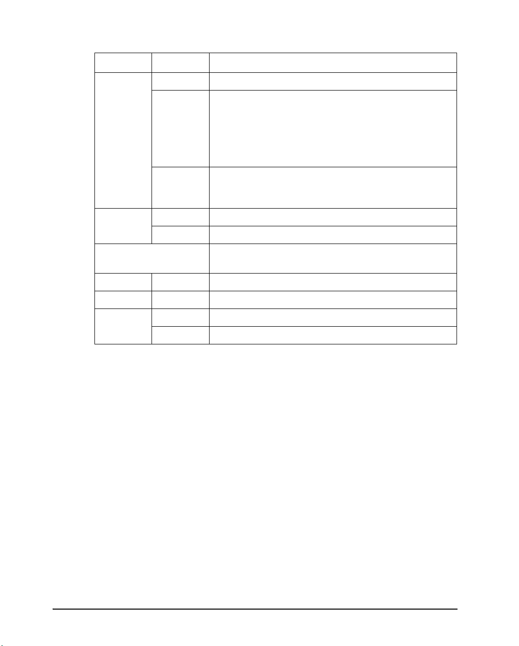
Control Panel Operations
—: This operation has no connection with this condition.
N/A: The condition does not apply because this operation is executed before poweringon.
1
2
Fault
Required Action
Operation
Load continuous forms
Required Conditions
Ready Printing
— Not printing On Press FF/Load.
paper
Load single sheet paper — Not printing On Press FF/Load if single
sheetload is switched from
AUTOto MANUAL in Set-Up
mode.
Feed paper a page — Not printing Off Press FF/Load.
Feed paper a line — Not printing Off Press LF.
Advance perforation to
tear bar
— Not printing Off Press Pause if the TEARop-
tion is switched from
AUTOto MANUAL in Set-Up
mode,or press FF/Load.
Advance paper for
viewing
— Not printing Off Press Pause if the TEARop-
tion is switched from
AUTOto MANUAL in Set-Up
mode.
Return paper to previous
position
— Not printing Off Press Pause if the TEARop-
tion is switched from
AUTOto MANUAL in Set-Up
mode,or press FF/Load.
2-20
Eject single-sheet paper — Not printing Off Press FF/Load or Park or
turnthe printer off and on
again.
Unload continuous-
3
forms
— Not printing Off Press Park.
Pause printing On Printing Off Press Pause.
Resume printing Blinking Not printing Off Press Pause.
Resume printing after a
fault
Off Not printing On Clear error and press
Pause.
Page 31

Setting up the printer
Required Conditions
Operation
Resume printing after
paper-out
Place printer in Ready
state
Place printer in pause
state
Enter Normal mode N/A N/A N/A Turn power on without
Continuous Test Print N/A N/A N/A Turn power on while press-
Enter Macro selection
mode
Select Macro 1
Select Macro 2
Switch the protocol
Enter Top-of-Form
Adjustment mode
4
4
4
Ready Printing
Off Not printing On Load paper.
Off Not printing Off Press Pause.
On — Off Press Pause.
— Not printing Off Press Protocol.
— Not printing Off Press LF button and FF/
1
2
Fault
Off
Off
Off
Required Action
pressing any buttons
ing FF/Load.
Press Protocol(M1) and
Park(M2).
Press M1
Press M2.
Load button.
Move paper by
1/60inch
Use the adjustment
temporarily
Use the adjustment
permanently
Clear the adjustment Off — Off Press Top buttons.
Enter Set-Up mode N/A N/A N/A Hold the Setup/Quit buttons
Move cursor to select
a Set-Up Function or
Value
Move cursor to select
a Set-Up Option
Select a Set-Up
Function or Value
Off — Off Press
Off — Off Press Set-Up/Quit.
Off — Off Press Exit/Save.
Off Not printing Off Press
Off Not printing Off Press
Off Not printing Off Press
or button.
depressed and switch the
printer on.
or button.
or button.
or button.
2-21
Page 32

Setting up the printer
1
2
Fault
Required Action
Operation
Select a Set-Up
Required Conditions
Ready Printing
Off Not printing Off Press Exit/Save.
Value and move cursor to SAVE&EXIT
Quit Set-Up mode
Off Not printing Off Press Set-Up/Quit.
without saving values
Clear software-detected
errors
— — Blink-
ing
Press Pause.
Initialize the printer — — — Turn power off and on
again.
1 In Normal mode operation, all buttons except Pause are inactive in the Busy state in which the printer
isreceiving or printing data.
2 Not printing includes the following situations: the printer is ready and awaiting data, or the Pause button
ispressed and the printer is awaiting data, or the Pause button is pressed during printing.
3 This operation is available in the rear-feeding push-tractor mode.
4 Switching is not done if the printer is holding printing data.
Printer Acoustical Feedbacks
2-22
Except for paper handling and when the factory setting for beep is not changed, the
printer beeps in the following ways when you press a control panel button, as follows.
A short beep indicates that the printer accepts your pressing or specification.
A longer beep indicates that your specification is invalid.
In a certain mode, a middle long beep indicates that the specified mode becomes
activeand a short beep indicates the end of the mode.
When the Fault indicator lights, the printer also makes a longer beep.
Page 33

Paper Handling
3
Paper Handling
This chapter explains how your printer uses paper. Topics covered are:
Selecting paper
Overview of paper operations
Adjusting for paper thickness
Using single sheets
Using continuous forms (push-tractor feed and pull-tractor feed)
Feeding and positioning paper
Switching paper types
Tips for paper handling are given at the end of this chapter. Check that section if you
are using multipart forms, envelopes, or labels.
3-1
Page 34

Paper Handling
Selecting Paper
The printer can handle either single sheets or continuous forms. Single sheets, also
called cut sheets, include envelopes and noncontinuous, multipart forms. Continuous forms include labels and multipart forms fed into the printer using the forms tractors.
For best results, use paper that meets the specifications listed in the following table.
(See Appendix B, “Printer and Paper Specifications” for detailed specifications.) If
you are unsure of the suitability of a particular type of paper, try testing the paper or
consult your dealer.
Paper Specifications
Paper Size
LA48N LA48W
Continuous forms Width 102 to 267 mm
(4 to 10.5 in)
Length 102 mm (4 in) or greater 102 mm (4 in) or greater
Cut sheets Width 102 to 267 mm
(4 to 10.5 in)
Length 76 to 364 mm
(3 to 14.3 in)
102 to 420 mm
(4 to 16.5 in)
102 to 420 mm
(4 to 16.5 in)
76 to 420 mm
(3 to 16.5 in)
Paper Thickness and Number of Copies
Description
Thickness 0.35 mm (0.014 in) maximum total thickness.
Copies 1 to 5 copies, including the original.
For carbon-interleaved paper, the carbon counts as a copy.
3-2
Page 35

Overview of Paper Operations
The following levers and buttons are used in paper handling:
Paper select lever 1 at the top left corner of the printer
Paper thickness lever 2 at the top right corner of the printer
All buttons 5 on the control panel 3 (Primary and alternative functions are labelled
respectively above and under each button.)
The following figure shows the location of each lever, indicators, and buttons:
1 Paper select lever
Paper Handling
2 Paper thickness lever
3 Control panel
4 Indicators
5 Buttons
Printer Levers and Buttons
3-3
Page 36

Paper Handling
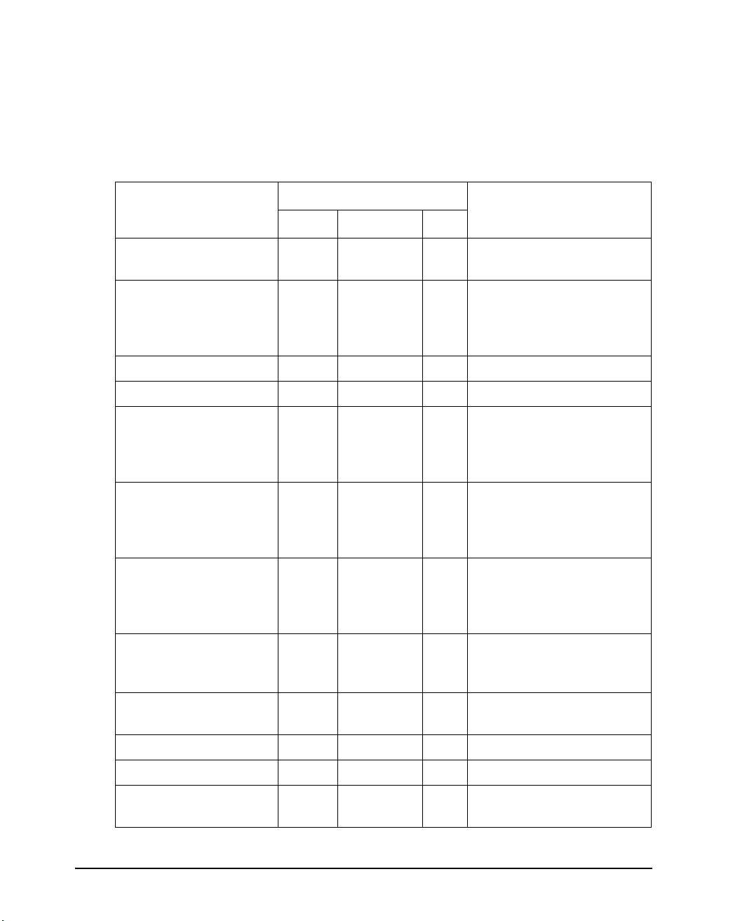
The following table summarizes the use of levers and buttons in paper handling.
More detailed information is provided later in this chapter.
CAUTION: To load or feed paper, the printer must be:
– In the Ready state but not receiving or printing data
– In the Pause state
Levers and Buttons Used for Paper Handling
Lever/Button Purpose Action
FF/LOAD Form feed
Load paper
LF Line feed Press LF to feed paper forward by
Park Unload forms Press Park to retract continuous
LF + FF/LOAD Enter Top-of-Form (TOF)
Adjustment mode
Exit/Save Save TOF value Press Exit/Save to permanently store
Increase TOF value by
1/60 inch
Decrease TOF value by
1/60 inch
Press FF/Load to execute a form
feed. Continuous forms are fed forward by one page. Single sheets are
ejected.
Press FF/Load to feed paper to the
top of form position.
one line.
forms to the “park position.”
Press LF and FF/LOAD buttons at
the same time to enter TOF Adjustment mode where the paper loading
position can be adjusted.
Press the button to feed paper forward by 1/60 inch in TOF Adjustment
mode.
Press the button to feed paper
backward by
1/60 inch in TOF Adjustment mode.
the TOF position adjusted by the
button and the
Adjustment mode.
button in TOF
3-4
Top Clear TOF adjustment Press the Top buttons at the same
time to clear the adjusted value and
return to the initial state.
Page 37

Lever/Button Purpose Action
Paper Handling
Pause Advance forms to the tear
bar when forms are at the
Top-of-Form (TOF) position.
Press Pause to advance the forms
perforation to the tear bar. Tear off
the forms, then press Pause again to
return theforms to the previous position.
Paper select
lever*
Select paper path Move the paper select lever forward
for single sheets.
Move the paper select lever backward for continuous forms.
Paper thickness lever
Adjust for paper thickness
or number of copies
Select the number corresponding to
the number of copies (including the
original). Vary the setting upward or
downward (including A to D) to optimize printing. Select D when replacing ribbon or clearing a paper jam.
* The following graphics are engraved on the casing.
Continuous forms
Cut sheets
3-5
Page 38

Paper Handling
Adjusting for Paper Thickness
The printer can handle paper with different thicknesses, including multipart forms
with up to five parts (original plus four copies). For details on paper thickness specifications, see Appendix B, “Printer and Paper Specifications”.
The paper thickness lever, located at the top right corner of the printer, allows you to
adjust for different paper thicknesses. Be sure to adjust the paper thickness lever
whenever you change the number of copies being printed.
The paper thickness lever has nine settings: 1 to 5 and A to D. Use the following
table to determine the appropriate setting for your paper; then, move the paper thickness lever to the appropriate position.
3-6
Paper thickness lever
Adjusting the Paper Thickness Lever
Page 39

Paper Thickness Lever Positions
Paper Handling
Number of Copies
(Including the Original)
1 copy 1
2 copies 2
3 copies 3
4 copies 4
5 copies 5
Ribbon replacement D
Position
For carbon-interleaved paper, the carbon counts as one copy.
Vary the position upward or downward (including A to D) to optimize printing. Select D when replacing a ribbon or clearing a paper jam. For labels and envelopes, use
the trial-and-error approachto determine a satisfactory position.
CAUTION: If printing is poor, the ribbon misfeeds, or the paper jams, move the lever
one position higher.
3-7
Page 40

Paper Handling
Using Single Sheets
This section describes how to load paper in the cut sheet stand. The cut sheet stand
allows paper to be loaded manually, one sheet at a time.
Loading a Single Sheet of Paper
To load a sheet of paper into the cut sheet stand:
1. Make sure that the printer is turned on. Check that rear-fed continuous forms are
retracted to the park position. (For details, see the section “Unloading Continuous Forms” later in this chapter.)
2. If necessary, reset the paper thickness lever. (See the section “Adjusting for
Paper Thickness” earlier in this chapter.)
3. Move the paper select lever forward. (This lever is at the top left part of the
printer.)
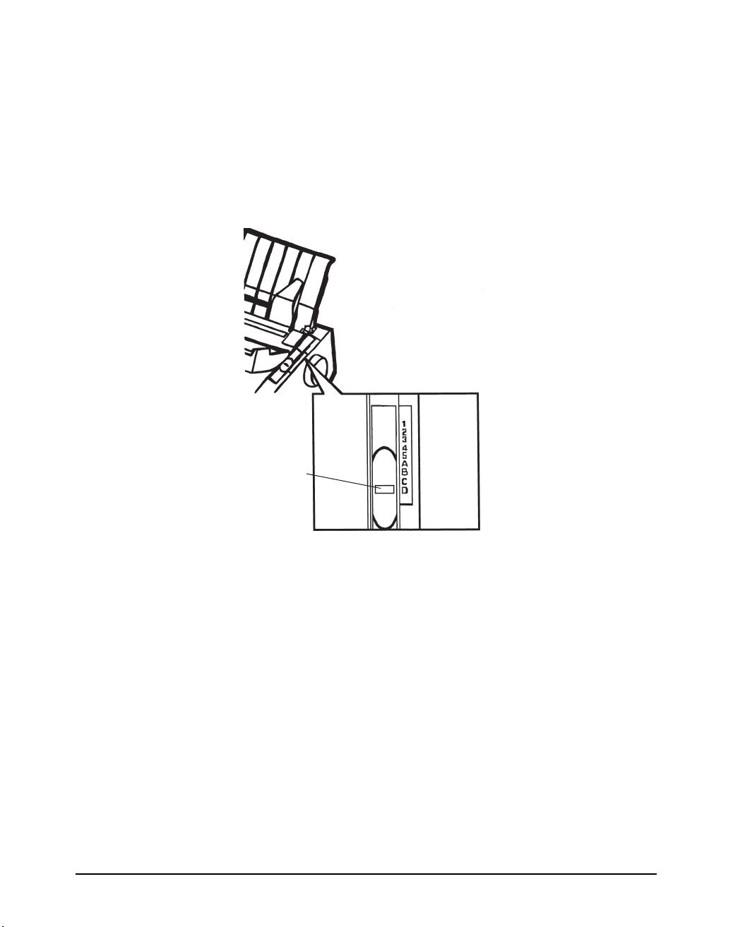
4. Raise the cut sheet stand. Position the left paper guide in accordance with the
Note below. Note that the movable range of the paper guide is limited.
NOTE: Below the left paper guide, the cut sheet stand has a scale graduated in units
of 0.1 inch. When the left paper guide is positioned all the way to the right,
the left margin is 5 mm (0.2 inch). To help align paper, also use the inchbased ruler on the top cover of the printer. The gradations on the ruler are
for 10 columns per inch.
Left margin
(minimum)
Preparing to load a sheet of paper
3-8
Page 41

Paper Handling
5. Adjust the right paper guide to the width of paper. Insert the paper into the cut
sheet stand. Make sure that the bottom edge of the paper engages snugly with
the platen. Thepaper will automatically advance to the top-of-form position if
the Single Sheet Load option of the Set-Up mode is set to Automatic.
NOTE: The factory setting for the Single Sheet Load option is automatic loading, two
seconds after paper detection. If you set this option to manual, you will have
to press FF/Load to feed the paper.
6. If you want to slightly adjust the Top-of-Form position, the first line on which
printing can start, adjust the Top-of-Form position of the paper using control
panel buttons. Press the Set-Up/Quit (Pause) button and the two Top buttons at
the same time. The M1/M2 indicator flashs alternately with the DEC and PPX24
indicators, indicating Top-of-Form Adjustment mode. Press the
button or the
button. The paper will move forward or backward in 1/60-inch increments.
Press the Set-Up/Quit button after adjusting the position. Note that this adjustment is temporarily saved. It will not be active at next power-up of the printer.
For permanent adjustment, see the section “Feeding and Positioning Paper” later
in this chapter.
Loading a sheet of paper
3-9
Page 42

Paper Handling
7. Place the printer in the Ready state. Print a sample page and check the page mar-
gins. Make the following adjustments, as necessary:
Horizontal alignment. Readjust the paper guides if required.
Top-of-form setting. Use the printer Set-Up mode (see Chapter 5, “Using Set-Up
Mode”) or the TOF Adjustment mode (see the section “Feeding and Positioning
Paper” later in this chapter).
Margin settings. Use your software or the printer Set-Up mode (see Chapter 5,
“Using Set-Up Mode”).
Ejecting Single Sheets
If you print using software, each sheet is ejected automatically upon the completion
of the page printing. To manually eject sheets of paper:
Press the FF/Load button to execute a forward form feed.
Turn the platen knob.
3-10
Page 43

Using Continuous Forms
Continuous forms paper, fanfolded at the horizontal perforations, is ideal for printing
rough drafts and long files. The paper is fed into the printer using the forms tractors.
The forms tractors unit at the rear of the printer pushes paper from the rear to the platen. This is called push-tractor feeding.
Positioning the Paper Stack
Place the stack of continuous forms paper directly below the rear of the printer. After
the paper is installed in the printer, the paper path should look like this:
Good placement
Paper Handling
Bad placement
Placement of continuous forms
3-11
Page 44

Paper Handling
Loading Continuous Forms
This section explains how to use continuous forms. The tractor unit pushes continuous forms.
To load continuous forms paper:
1. Make sure that the printer is turned on. Remove any single-sheet paper from the
printer.
2. If necessary, readjust the paper thickness lever for continuous forms. (See the
section “Adjusting for Paper Thickness” earlier in this chapter.)
No. of Copies Setting
1 1 to 2
2 to 3 2 to 3
4 3 to 4
5 4 to 5
Paper thickness lever
3-12
Paper thickness lever setting
3. Move the paper select lever to the rear of the printer.
Continuous forms side
Preparing to load continuous forms paper
4. Release the tractor locking levers by pulling them up. Open the tractor paper
holders. See the following figure.
Page 45

Paper Handling
5. Position the right tractor (as seen from the rear of the printer). Push the right
locking lever down to secure the tractor. Center the middle forms support.
Cut sheet stand
Forms
tractors
Continuous
Locking levers
Tractor guide
Paper select lever
Positioning the tractors
forms side
Adjusting the left margin
Below the right tractor, as seen from the back, there is a tractor guide, short inchbased ruler graduated in 10 columns per inch. Use the ruler to help position the tractor. When the paper edge is positioned to the left most line, the left margin is approximately 12 mm (0.5 inch) including perforation area.
Tractor paper holders
Tractor paper holders
Ajusting the left margin
6. Fit the paper feed holes onto the left and right tractor pins. Adjust the left tractor
(as seen from the rear of the printer) to the width of the form. Close the paper
holders.
7. Pull the left tractor (as seen from the rear) to stretch the paper taut. Push the left
locking lever down to secure the tractor in place.
3-13
Page 46

Paper Handling
8. Strongly pull the back cover off of the cut sheet stand (in the direction indicated
9. Install the cut sheet stand. For installation, see the section “Installing the Cut
10. Press the FF/Load button to advance the paper to the top-of-form position.
11. Press the ONLINE button to place the printer online. Print a sample page and
by the arrow) and set it down.
Cut sheet stand
Back cover
Setting the back cover
Sheet Stand” in Chapter 2.
Top-of-form is the first line on which printing can start.
check the page margins. Make the following adjustments, as necessary:
3-14
Horizontal alignment. Move the forms tractors as required.
Top-of-form setting (see Chapter 5, “Adjusting Top-of-Form Origin”).
Margin settings. Use your software or the printer setup mode (see Chapter 5,
“Using Set-Up Mode”).
If the paper cut position and the perforation position do not fit, adjust them by using
the following procedure.
Page 47

Paper Handling
NOTE: When you use continuous forms, make sure that the edges of both left and
right paper guides do not touch the paper. Slide both paper guides flush
against the ends of both sides.
Good Unacceptable
Continuous
Left paper
guide
Adjustment of the paper guides
form
Cut sheet
stand
Right paper
guide
Adjusting the Tear-off position
When the FF/Load button is used to advance the paper to cut it, the paper cut position and the perforation position may not match. In such cases, adjust their positions
by using the following procedure.
Adjustment procedure
1. Use the FF/Load button to advance the paper to its cut position.
2. Press Park and FF/Load buttons simultatneously to enter adjustment mode.
3. Adjust the Tear-off position by using the following buttons:
button: Pressing this button once extends the paper feed amount by 1/180
inches.
button: Pressing this button once reduces the paper feed amount by 1/180
inches.
Exit/Save button: Saves the adjusted value and exits the adjustment mode.
Setup/Quit button: Exits the adjustment mode without saving the adjusted value.
NOTE: The adjustment range is plus or minus 63/180 inches (approximately 9 mm).
When it is exceeded, an alarm beeps.
3-15
Page 48

Paper Handling
Unloading Continuous Forms
To unload continuous forms:
1. Make sure that the paper select lever is set to the rear position.
2. Press the Park button. The continuous forms paper is retracted to the park posi-
tion. If the paper cannot be retracted in one operation, continue to press the
Park button until the paper is parked.
NOTE: The printer can retract continuous forms paper a maximum of 55.8 cm (22
inches) per operation.
3. To remove the paper, raise the tractor paper holders and lift out the paper.
Installing the Tractor Unit
Install the tractor unit by following the procedure below if it happens to be disengaged from the studs.
1. Turn off the printer.
2. Remove the cut sheet stand and open the acoustic cover.
3. Hook the notch of the tractor unit against stud 1, and then rotate the unit down-
ward so as to set the other notch onto stud 2.
Acoustic cover
Stud 1
Stud 2
Stud 1
Stud 2
Tractor unit installation
3-16
Page 49

Paper Handling
Tearing Off Continuous Forms
Your printer has a special “tear-off edge” that allows you to tear off printed pages
without wasting paper. The tear-off edge is located on the ejection cover.
To tear off continuous forms using the tear-off edge:
1. Press the FF/Load button. The bottom perforation of the last page advances to
the tear-off edge. If you specified TEAR: AUTO using the INSTALL function
in setup mode, the paper automatically advances to the tear-off edge at the end of
each job (or when the printer has printed all the data received).
NOTE: If the bottom perforation of your paper is not positioned at the tear-off edge,
the length of your paper may not be specified correctly in your software or
the printer setup mode. Check that the paper length is specified correctly.
For information on specifying page length using setup mode, see Chapter 5,
“Using Set-Up Mode”.
2. Tear the paper off at the perforation.
Tearing off continuous forms
3. Press any button to retract the forms back to the top-of-form position.
3-17
Page 50

Paper Handling
Feeding and Positioning Paper
Print Area Definition
TOF (Top-of-Form): This value defines the distance between the edge of the pa-
per and the place where you allow the printing to begin (position of line
number 1). You can adjust this distance according to the condition of your paper
(for example, pre-printed forms). When you load the paper, the printer feeds the
paper to this position, waiting for printing commands.
L (Form Length): Set the corresponding Set-Up option (FORM LENGH) accord-
ing to the actual physical page length (distance between two perforations for continuous forms). This will allow the printer to know exactly where the print head
is and to position it at the same position when a form feed occurs.
Top line 1: This is the line where the printing actually starts. To define a top mar-
gin, select the number of this line within Set-Up mode (TOP MRGN option). Example: In the following picture, TOP MRGN option is set to 3.
Bottom line 2: This is the line where the printing actually stops. To define a bot-
tom margin, select the number of this line within Set-Up mode (BOTTOM MRG
option). Example: In the following picture, BOTTOM MRG option is set to 50.
Left column 3: This is the column where the printing actually starts. To define a
left margin, select the number of this column within Set-Up mode (LEFT MARGN option). Example: In the following picture, LEFT MARGN option is set to 4.
Print area 4: Print area defined by the corresponding Set-Up options: Form
Length, Top-of-Form, Top Margin, and Bottom Margin.
Paper perforation 5: The perforation defines the physical page length.
3-18
Page 51

Paper Handling
1
2
3
4
5
6
7
8
... ...
48
49
50
51
52
12345
ABCDEFGHIJ ···
ABCDEFGHIJ ···
ABCDEFGHIJ ···
...
6
TOF
L
TOF
1
2
3
4
5
6
...
Print Area Definition
3-19
Page 52

Paper Handling
Line Feed/Form Feed
Use the line feed/form feed function to move paper forward. This function is valid
whenever the printer is not receiving or printing data and has no fault. Pressing the
LF button advances the paper one line. Pressing the FF/Load button feeds one sheet
of paper.
Except using the Park button for unloading paper or using the Top-of-Form Adjustment mode for fine-adjusting the Top-of-Form position, you are not allowed to execute “reverse” feed from the control panel. To feed paper backward, manually rotate
the platen knob. Remember that the Top-of-Form will slip from the original setting.
Top-of-Form Adjustment
NOTE: For Top-of-Form definition, see the previous section “Print Area Defini-
tion”.
The Top-of-Form adjustment is available for single sheets or continuous forms fed
by the push-tractor. The adjustment is reflected to the Top-of-Form setting of Macro
1 or Macro 2 currently selected from the control panel.
NOTE: This adjustment is not available for continuous forms fed by the pull-tractor.
You can adjust the Top-of-Form value within the range from 0 to 99/60 inches.
NOTE: The horizontal embossed rib under the red cursor on the print head carriage
corresponds to the base line of the characters to be printed.
1. Position the paper at the current Top-of-Form position:
For continuous forms, park the paper, then press the FF/LOAD button.
For a single sheet, simply insert the sheet in the cut sheet stand.
Paper is automatically fed to the Top-of-Form position, if the Set-Up option
S-SHEET LD (Single Sheet Load) is set to AUTO. Otherwise, press the
FF/LOAD button.
2. Make sure the is in the pause state (Offline). Press the Pause button if necessary.
Enter the Top-of-Form mode by pressing the LF and FF/LOAD buttons at the
same time. The printer beeps and the M1/M2 indicator flashes alternately with
the DEC and PPX24 indicators, indicating the Top-of-Form mode.
3-20
Page 53

Paper Handling
3. Adjust the Top-of-Form value:
To increase the Top-of-Form value of a 1/60 inch, press the button.The pa-
per moves forward.
To decrease the Top-of-Form value of a 1/60 inch, press the button.The pa-
per moves backward.
To reset the Top-of-Form value to 0, press the Top button. The paper moves
to the edge of the page (position 0).
NOTE: If you reach the limit of the permitted range, the printer beeps, and the paper
stops moving.
4. Save the Top-of-Form value:
To permanently save the value, press the Exit/Save button. The printer returns
to Normal mode.
To temporarily save the value, press the Set-Up/Quit button. The printer re-
turns to Normal mode. (The new value is lost at the next power-off.)
NOTE: The use of the and buttons for micro-feeding is available for some
cases of software errors (Fault indicator blinking).
NOTE: If you want to clear the adjusted TOF position and to return to the initial
state, press the Top buttons at the same time.
3-21
Page 54

Paper Handling
Switching Paper Types
If you have more than one type of job, it is often necessary to switch between continuous forms and single sheets. This section explains how to switch between paper
types. It is not necessary to remove the continuous forms paper from the printer.
CAUTION: This function is not available for continuous forms paper that is fed by
the pull-tractor.
Switching from Continuous Forms to Single Sheets (Push-Feed Mode)
To switch from continuous forms to single sheets:
1. Tear off your printed pages.
2. Retract the forms paper to the park position by pressing the Park button. The
Fault indicator turns on.
CAUTION: Retracting many pages by using the Park button without tearing off will
cause paper jams. To avoid damage to your printed pages, be sure to
tear off the printed pages before retracting the continuous forms paper.
3. Move the paper select lever forward to the single sheet position.
4. Raise the cut sheet stand to the up position. (For details see the section “Using
Single Sheets” earlier in this chapter.) Put a sheet of paper on the cut sheet stand
with its bottom edge aligned with the platen. The paper automatically advance
to the top-of-form position if the option S-SHEET LD (Single Sheet Load) is set
to AUTO. Otherwise, press the FF/LOAD button to advance the single sheet
paper to the top-of-form position.
You are now ready to print using single sheets.
Switching from Single Sheets to Continuous Forms (Push-Feed Mode)
To switch from single sheets to continuous forms:
1. If a sheet of paper is loaded, remove the paper by turning the platen knob or
pressing the FF/LOAD button.
2. Move the paper select lever to the rear to the continuous forms position.
3. Press the FF/LOAD button. The continuous forms paper advances from the
park position to the top-of-form position.
You are now ready to print using continuous forms paper.
3-22
Page 55

Tips on Paper Handling
General Tips
Use high-quality paper. Do not use paper that is wrinkled or curled at the edges.
Do not use paper with staples or metal parts.
Do not use paper with unpredictable variations in thickness, such as paper with
partial multilayers, paper with embossed printing, or labels with the backing
sheet exposed.
Store paper in a clean, dry environment.
Multipart Forms
Avoid using carbon-interleaved single sheets if possible. Printing tends to be-
come misaligned on the bottom sheet.
Set the paper thickness lever to best accommodate the multipart form thickness.
To ensure smoother feeding of paper-stapled, multipart forms, raise the cut sheet
stand to support the forms.
Paper Handling
Envelopes
When printing envelopes, use the cut sheet stand. Note the following:
Set the paper thickness lever to best accommodate the envelope thickness.
When loading envelopes, make sure that the envelope flaps face forward. Other-
wise, the envelopes may jam in the printer.
Labels
Be careful to check operating conditions when using labels. Labels are sensitive
to temperature and humidity.
Only use labels mounted on continuous forms backing sheets. Do not print labels
mounted on single sheet backing. Labels mounted on single sheet backing tend to
slip and printing becomes crooked.
Do not leave labels loaded in the printer. If labels curl around the platen, jamming
may occur when printing is resumed.
Set the paper thickness lever to best accommodate the label thickness.
3-23
Page 56

Paper Handling
Test-print labels before running a job. If jams occur, set the paper thickness lever
to a wider position. If jamming problems continue, try a different type of label.
3-24
Page 57

Printing
This chapter describes the following typical printing operations:
Selecting print features
Starting, stopping, or resuming printing and viewing last printed lines
Removing printed pages
Selecting Print Features
The print features you select determine how your printer interprets commands from
the computer and how your printed pages will look. For example, print features include the following:
Protocol (M1/M2)
Printing
4
Font
Pitch (characters per horizontal inch)
Line spacing (lines per vertical inch)
Page length and margins
To select print features, you can use either commercial software or the printer control
panel. The method you use depends on the capabilities of your software. If your
software has most of the features you require, you may rarely – if ever – have to use
the control panel. In fact, your software mostly overrides the printer settings.
If your software has limited options, you can use the printer control panel to select
print features. Sometimes, the control panel enables you to select features not available through your software. For example, you can select downloaded fonts not supported by your software.
Using Commercial Software
Many commercial software packages offer a wide variety of print features, including
some features that are not supported by this printer. For example, software often provides a wider range of font sizes than the printer can accommodate. Software also
allows you to specify multiple fonts on a page. To determine which features your
software supports and how to select them, refer to your software documentation.
4-1
Page 58

Printing
Using the Control Panel
This printer can directly select some print features from the control panel. These features, listed on the control panel, are two predetermined sets (macros) of print features and three protocols. Use the following procedures to select Macros and
Protocols:
Macrol selection
1. Press the Protocol M1 and the Park M2 buttons simultaneously to enter Macro
selection mode. The M1/M2 indicator starts blinking.
2. Then press within 3 seconds Protocol M1 button to select macro 1 or Park M2
button to select macro 2. If macro 1 is selected, the M1/M2 indicator lights, if
macro 2 is selected the M1/M2 indicator is off.
4-2
Macro select mode
3. Press the Pause button to return the printer to the Ready state. You are ready to
print using the selected macro.
NOTE: The active Macro at power-off remains active at next power-up.
Page 59

Printing
Macro 1 and Macro 2 Settings
When you switch from one macro to another, each modification you made using the
control panel for the Top-of-Form option or the Protocol option is lost, and the values
of these options stored in the new macro become active.
The following tables list default values of options for print features. The former is
for options in Macro 1 and Macro 2 and the latter is for options independent of Macro
selection.
Print Feature
Protocol
Protocol serial
Protocol parallel
Protocol USB
Font
Horizontal pitch
Verti cal pi tch
Form length
Left margin
Top of Form
Top ma rg in
Bottom margin
Line mode
Paper source
Print direction
DEC defaults
DEC printer ID
Auto wrap
EOT disconnect
Initial report
Auto answerback
Answerback on ENQ
DEC G0 character set
DEC user preference character set
IBM&Epson
Default Character set CP 437 CP 437
IBM defaults
IBM set 1 or 2
IBM double height
IBM AGM
1
2
Factory Settings
Macro 1 Macro 2
Port dependent
DEC PPL2
EPSON-ESC
EPSON-ESC
Draft
10 cpi
6 lpi
11 inches
1 column
0/60 inch
1 line
66 lines
LF = LF, CR = CR
Tr ac t o r
Soft control
PPL2
Wrap
No disconnect on EOT
No
No
No
US ASCII
DEC Supplemental
IBM set 1
No
No
Port dependent
DEC PPL2
IBM PPX24
IBM PPX24
Draft
10 cpi
6 lpi
11 inches
1 column
0/60 inch
1 line
66 lines
LF = LF, CR = CR
Tr ac to r
Soft control
PPL2
Wrap
No disconnect on EOT
No
No
No
US ASCII
DEC Supplemental
IBM set 1
No
No
4-3
Page 60

Printing
Print Feature
Factory Settings
Macro 1 Macro 2
Epson defaults
Epson national character
USA USA
set
1 When you change the Macro selection and the new Top-of-Form value is different from the former,
paper is automatically fed to the next page, using the new Top-of-Form value.
2 When you change the Macro selection and the paper source selection is different, the printer auto-
matically parks the continuous forms (in Push-Feed mode only) or ejects the cut sheet. The Fault
indicator blinks, indicating you should change the position of thepaper select lever.
NOTE: You cannot attempt to change the Macro selection when the printer is print-
ing, even if you switch to the Pause state.
4-4
Page 61

Installation Settings
Print Feature Factory Settings
Printing
Language
Te ar
Single sheet loading
Error beep
Buffer 64 Kbytes
Interface type
Auto interface switch time
Baud rate
Bits and parity
Buffer control
Disconnected on fault
Area control
Gather control
Tear off control
Skip control
English
Auto, 1 second
Auto, 2 second
One
Automatic sense
2 seconds
9600 bps
8 bits and none
XON/XOFF
No
No
No
Speed
Ye s
Adjustments Settings
Print Feature Factory Settings
Fanfold adjust (continuous forms)
Manual adjust (single sheets)
Reserved 1
Reserved 2
Manual adjust 2
Fanfold adjust 2
Fanfold adjust 3
Reserved 3
0/60 inch
0/60 inch
0/60 inch
0/60 inch
0/30 inch
0/30 inch
0/30 inch
0/30 inch
Menu Access Settings
Print Feature Factory Settings
Menu access All functions allowed
4-5
Page 62

Printing
Changing the Protocol
When you first turn the printer on, the active protocol depends on what port will be
used for printing.
For Macro 1: If you use the serial port, the active protocol will be the DEC pro-
tocol.
If you use the parallel port, the active protocol will be the Epson
protocol.
If you use the USB port, the active protocol will be the Epson protocol.
For Macro 2: If you use the serial port, the active protocol will be the DEC pro-
tocol.
If you use the parallel port, the active protocol will be the IBM protocol.
If you use the USB port, the active protocol will be the IBM protocol.
This printer has three protocols and allows you to set the protocol mode in one of the
following three ways: the printer engages one of the three protocols, automatically
determines the active protocol, or assigns different protocols for parallel, serial or
USB interfaces.
To change the protocol: Repeatedly press the Protocol button. The DEC and PPX24
indicators turn on and off. The combination of lighted indicators shows the protocol
mode selected, according tothe next table.
Changing the protocol
4-6
Page 63

Printing
Indicator Status Active Protocol
DEC lit DEC ANSI protocol is active
PPX24 lit IBM Proprinter X24E/XL24E protocol is active
Both indicatorts lit Epson ESC/P2 protocol is active
Flashing alternately According to Set-Up settings, the printer waits for data to
switch to a proper protocol.
4-7
Page 64

Printing
Starting or Stopping Printing
Starting Printing
Before you start to print, make sure that paper is loaded. Also, verify that the paper
thickness lever is set to the appropriate position (1 to D).
To start printing, make sure that the Ready indicator is lit (the printer is ready). If not
so, press the Pause button to place the printer in the Ready state. Then start your software.
Stopping and Viewing Printing
To stop printing, press the Pause button to place the printer in the Pause state. The
printer stops after printing the current and next lines. You can also use your software
to stop printing, but there will be a slight delay before printing stops. After the printer
enters the Pause state, it still receives data until the print buffer becomes full of new
data. The data in the print buffer will be lost if you turn the printer off.
When the printer stops printing, the paper is advanced to the viewing position so that
you can view the last printed lines. This function is valid for single sheets and continuous forms in push-tractor feed mode but not valid for continuous forms in pulltractor feed mode.
Resuming Printing
To resume printing, press the Pause button again. If the paper is advanced for viewing, it is backed to the previous position before printing. To cancel printing, use the
cancel commands provided by your software or computer. To clear the print buffer,
turn the printer off. Any data sent to the print buffer before you canceled printing will
be lost.
Resuming from a Paper-Out
The printer can “sense” when paper runs out. The printer stops printing and lights the
Fault indicator. To resume printing when paper runs out, follow the procedures described below:
1. Install paper on the forms tractor unit or on the cut sheet stand as described in
Chapter 2, “Setting up the printer”.
2. To load the first sheet of paper, press the FF/LOAD button for continuous forms.
Single sheets are automatically loaded unless you change the factory setting. The
Fault indicator will turn off and the printer resumes printing.
4-8
Page 65

Printing
CAUTION:For continuous forms paper, the page where printing stopped and the
page where printing resumes may be incorrectly printed. In this case,
wait for the entire job to finish printing. Then reprint the incorrect pages.
4-9
Page 66

Printing
Removing Printed Pages
This section describes the best methods for removing single sheets or continuous
forms paper after printing.
Removing Single Sheets
When you print using software, the printer automatically ejects each sheet of paper
when the end of the printed page is reached. To eject sheets manually:
Press the FF/Load button to execute a form feed.
Removing Continuous Forms
To avoid wasting paper when removing printed continuous forms paper, use the
printer's tear-off function.
Depending on the TEAR option value of the Set-Up, the printer automatically feeds
the paper so that the perforation faces the tear bar. Tear the paper off. The paper will
automatically return to the Top-of-Form position when the printer receives data to
print.
If you have set the TEAR option to MANUAL, you have to press the Pause button
to move the paper to the tear bar, and then to return the paper to the Top-of-Form position.
NOTE: See the section “Tearing Off Continuous Forms” in Chapter 3, “PaperHan-
dling”.
4-10
Page 67

Your Printer has two operation modes:
The Normal mode is used for daily operations like paper handling and printing as
explained in Chapter 3, “Paper Handling” and Chapter 4 “Printing”.
The Set-Up mode is used to change the printer settings that affect the daily oper-
ations.
What is Set-Up Mode for?
The Set-Up mode allows you:
To define the two user environments, Macro 1 and Macro 2, which prepare two
sets of printer operating environments for your application software. Printer operating environments include the protocol, font, horizontal and vertical pitches,
page length and margins, line mode, and printing direction. They also include
protocol dependent options like the character set.
Using Set-Up Mode
5
Using Set-Up Mode
To check your settings by printing a list of all the printer’s currently selected val-
ues.
To define general installation parameters related to the integration in your envi-
ronment (e.g., menu language, tear-off control, auto-load control, and interface).
To fit Top-of-Form adjustments for paper feed control.
To help diagnose your printer for trouble-shooting by printing test and hexadeci-
mal dumps.
To recall all the factory settings (including both user environments, installation
parameters, and adjustment parameters).
To define what kind of settings modifications are allowed to avoid accidentally
changing of Set-Up values.
5-1
Page 68

Using Set-Up Mode
How Set-Up Works
The Set-Up mode consists of Set-Up functions which correspond to the printer settings described in the previous page. Each function generally has many options
which correspond to the print features to be changed. Each option includes many parameters values to be selected. All the Set-Up functions, options, and values are
printed in a logical sequence on the paper when you enter the Set-Up mode, including
the usage of buttons. You can perform all the Set-Up operations by using buttons on
the control panel in the following order:
Navigating through the option menu structure.
Selecting a new value for an option.
Saving your new printer configuration (permanently or temporarily).
For information on using the printing test and hex dump functions, see the section
“Using the Diagnostic Functions” later in this chapter.
Entering the Set-Up Mode
Before entering the Set-Up mode, load continuous feed paper on the tractors as described in the section, “Using Continuous Forms,” in Chapter 2. Several sheets of
paper may be required to make all of your Set-Up mode selections. Of course, you
can use single sheets.
5-2
NOTE: We recommend the use of the push-tractor mode in order to avoid paper
jams.
To enter the Set-Up mode:
1. Make sure that the tractors are loaded with continuous feedpaper and that the
paper select lever is set backward.
2. Turn the printer off.
3. Turn the printer back on while pressing the two Set-Up/Quit buttons until the
printer beeps.
4. Open the front cover in order to see the printed text.
Page 69

Using Set-Up Mode
5. When the printer enters the Set-Up mode, it prints the following information.
During the Set-Up mode, the M1/M2 indicator flashes.
1
2
4
MACRO 1
3
Initial printout in setup mode
The initial printout contains a header, help menu 1, and <FUNCTIONS> menu 2.
The header tells you that the printer is in the Set-Up mode. The help menu provides
a quick summary of how to use buttons in the Set-Up mode.
The <FUNCTIONS> menu
Generally speaking, the red cursor
2 lists all of the functions available in the Set-Up mode.
3 on the plastic print guide 4 indicates the function
or value to be selected. When entering the Set-Up mode, the red cursor is initially
positioned under MACRO 1.
5-3
Page 70

Using Set-Up Mode
Overview of the Set-Up Mode
When you enter the Set-Up mode, the following <FUNCTIONS> menu is printed:
<FUNCTIONS>
MACRO 1 MACRO 2 PRINT INSTALL ADJUST TESTS RCALL-FACT MENU-ACCESS SAVE&EXIT
The following table summarizes the purpose of each function.
Set-Up Mode Functions
Function Purpose
MACRO 1 and MACRO 2 Assigns print features to MACRO 1 and MACRO 2
PRINT Prints the Printer Configuration
INSTALL Changes the Set-Up menu language, computer inter-
face, and paper feed control options
ADJUST Changes the top-of-form fine adjustment options
TESTS Runs the printing test and hex dumps
RCALL-FACT Resets factory settings in MACRO 1, MACRO 2,
INSTALL and ADJUST
MENU-ACCESS Restricts access to Set-Up functions from the control
panel
SAVE&EXIT Exits the Set-Up mode and saves any changes made
in the Set-Up mode
To select a function from the <FUNCTIONS> menu:
1. Repeatedly press the button or the button to position the red cursor on the
plastic print guide under the function you require.
2. Press the button or the button to select the function. If the function has
options and values, the printer prints the first option and its values.
The MACRO 1, MACRO 2, INSTALL, ADJUST, TESTS, and MENUACCESS functions contain options that have selectable values. The other functions have neither options nor values.
5-4
Page 71

Using Set-Up Mode
3. After selecting the desired values, press the Exit/Save button to reprint the
<FUNCTIONS> menu where the red cursor is positioned beneath SAVE&EXIT.
For each option, the bolded value is the current default value (the value currently
savedin the printer’s permanent memory). In the previous example, the default
values are PORT DEPND (Port Dependent) for protocol selection and DRAFT
(Draft) for font selection.
Example: Changing the Vertical Pitch
To become familiar with the Set-Up mode, try the following example. This example
shows how to change the vertical pitch in Macro 2 from 6 lines per inch to 8 lines per
inch.
1. Enter the Set-Up mode.
Turn the printer off and back on while pressing the Set-Up/Quit button until the
printer beeps.
2. Select the Macro 2 function.
Wait for the printer to stop printing and press the
red cursor on the plastic guide of the print head under MACRO 2. Press the
button or the
COL> option and its values.
button to select the Macro 2 function and print the <PROTO-
button once to position the
3. Print the menu of the vertical pitch option.
Since you only want to change the vertical pitch, press the
current protocol. Bolded PORT DEPND is underlined, and the next option
<PRTCL SERL> is printed. (The bolded value indicates the current setting, and
the underlined value is the new setting.) Repeatedly press the
same way until the <VERT PITCH> option and its values are printed.
4. Change the vertical pitch from 6 to 8 lines per inch.
Press the
button to select 8 LPI. 8 LPI is underlined, and the next option, <HORZ
PITCH>, and its values are printed.
5. Exit the Macro 2 function.
Since you do not want to make any other changes in MACRO 2, press the Exit/
Save button. The <FUNCTIONS> menu is then reprinted, and the red cursor is
positioned beneath SAVE&EXIT.
button once to position the red cursor beneath 8 LPI. Press the
button to select the
button in the
5-5
Page 72

Using Set-Up Mode
6. Exit the Set-Up mode, saving or not saving the new vertical pitch.
Press the
default in Macro 2, and then exit Macro 2. The printer exits the Set-Up mode
and returns to the Ready state. These settings remain in effect until the next time
they are changed.
Press the Set-Up/Quit button if you do not intend to save these settings in
Macro 2.
button or the button to save 8 lines per inch as the new power-on
5-6
Page 73

Using Set-Up Mode
Options with Undetermined Values
For some options, you can choose among a continuous range of many values. These
options are identified as follows:
<XXX-No of INCH>, which means the unit of the range is the Inch.
<XXX-No of COLM>, which means the unit of the range is the Column.
<XXX-No of LINE>, which means the unit of the range is the Line.
When you select such an option, only the current value is printed. The numeric range
of these respective options are from 1 to 256, from 0 to 255, or from 0 to 99.
To select such a value:
1. Press the button or the button (the printer beeps) as many times as you
decrease from or increase to the current value. If you change the value by a wide
margin, you can keep the button pressed continuously; the printer beeps at intervals of 0.2 seconds. The number of beeps corresponds to the number of times
you press the button.
2. When you stop pressing the button, the new value is printed to the right of the
current value.
3. If this new value is not satisfactory, repeat step 1 until the next new value is sat-
isfactory.
Range Management for a Wide Range of Values
The permitted range of these values may be limited as to physical range.
If you intend to change to a value which is outside of the permitted physical range,
the actual current value will be the highest possible value considering other Set-Up
dependent values and may not match the value displayed.
See the Options tables to ascertain the permitted range.
Example: Changing the Left Margin
This example shows how to change the left margin in Macro 2 from column 1 to column 20.
1. Enter the Set-Up mode.
Turn the printer off and back on while pressing the Set-Up/Quit button until the
printer beeps.
5-7
Page 74

Using Set-Up Mode
2. Select the Macro 2 function.
Wait for the printer to stop printing. Then press the
the red cursor on the plastic guide of the print head under MACRO 2. Press the
button or the button to select the Macro 2 function and print the <PROTO-
COL> option and its values.
3. Print the menu of the left margin option.
Since you only want to change the left margin, press the
current protocol. The bolded PORT DEPND is underlined, and the next option
<PRTCL SERL> is printed. (The bolded value indicates the current setting, and
the underlined value is the new setting.) Repeatedly press the
<LEFT MARGN> option and its value are printed.
4. Change the left margin from column 1 to column 20.
Press and hold the
button is released, the new value is printed next to the current value. If the new
value is not 20 COL, repeat this operation. If it is 20 COL, press thebutton to
select 20 COL. 20 COL is underlined, and the next option, <TOP OF FRM>,
and its value are printed.
5. Exit the Macro 2 function.
Since you do not want to make any other changes in MACRO 2, press the Exit/
Save button. The <FUNCTIONS> menu is then reprinted, and the red cursor is
positioned beneath SAVE&EXIT.
button once to position
button to select the
button until the
button until the printer beeps nineteen times. When the
6. Exit the Set-Up mode, saving or not saving the new left margin.
Press the
button or the button to save 20 columns as the new power-on
default in Macro 2 and exit Macro 2. The printer then exits the Set-Up mode and
returns to the Ready state. These settings remain in effect until the next time they
are changed.
Press the Set-Up/Quit button if you do not intend saving these settings in
Macro 2.
Options with Both Pre-determined and Undetermined Values
Some options include both types of values. Undetermined values appear at the end
of the list of pre-determined values, identified by the unit of the corresponding range.
For example, when you select the <FORM LENGH> option (Form Length), the following menu is printed:
<FORM LENGH>
3 INCHES 3.5 INCHES 4 INCHES 5.5 INCHES 6 INCHES 7 INCHES 8 INCHES
8.5 INCHES 11 INCHES
11 2/3INCH 12 INCHES 14 INCHES 15 INCHES No of LINE
5-8
Page 75

Using Set-Up Mode
1. Select the No of LINE value.
A new option menu with undetermined values is printed.
2. Change the value according to the previous procedure.
The chart on the next page summarizes how to select options such as protocol and
font and how to use the functions that do not have options.
5-9
Page 76

Using Set-Up Mode
Enter Set-Up mode:
Turn power on with Set-Up/Quit pressed
Printer prints <FUNCTIONS> menu
Select function: Press or
to position the cursor,
then press or
One of the following functions is selected
PRINT (list of defaults) and
RECALL FACTORY DEFAULTS
MACRO1, MACRO2,
INSTALL, ADJUST,
and MENU ACCESS
Reprint <FUNCTIONS> menu
Press Exit/Save
Select values: Press or
to position cursor,
then press or
Press Set-Up/Quit
*1
Printer exits Set-Up mode
without saving changes
: Functions having options and/or values
*1 Changes are valid, but will be lost at next power-off.
*2 Changes will remain valid at next power-on.
(PRINT TEST and HEXDUMP)
TESTS
SAVE&EXIT
Press
or
*2
Printer saves changes and
exits Set-Up mode
Select values: Press or
to position cursor,
then press or
5-10
Page 77

Using Set-Up Mode
Points to Remember
We recommend that you use continuous forms paper for printing in the Set-Up
mode because the output will exceed a single page. To load paper, use the FF/
Load button. To adjust the line position of the paper in the Set-Up mode, use the
platen knob.
Whenever you enter the Set-Up mode, short help menus are printed at the top of
the page. Help menus are also printed when you select the TESTS function. Use
the help menus for quick reference while in the Set-Up mode.
When printing the options and values for each function, you can move either for-
ward or backward in the option list. To move forward (print the next option), press
the
button. To move backward (print the previous option), press the button.
You can skip printing the value list for the undesired options by pressing and
holding down these buttons.
While in the <FUNCTIONS> menu or when selecting a function that contains op-
tions and selectable values, press the Exit/Save button to reprint the <FUNCTIONS> menu. In this case, the red cursor is positioned beneath SAVE&EXIT.
A bolded (overprinted) value indicates that it is the current setting. An underlined
value indicates a selected setting.
While in the Set-Up mode, you can use the PRINT function to print out a list of
the currently selected values. (See the next section for details.)
To exit the Set-Up mode and permanently save your changes, select the
SAVE&EXIT function. For details, see the section “Save Settings and Exit Setup mode” later in this chapter.
To exit the Set-Up mode and temporarily use your changes, press the Set-Up/
Quit button. Your previous power-on settings will be active when you turn the
printer on again.
5-11
Page 78

Using Set-Up Mode
Printing the Printer Configuration
The PRINT function prints a list of all the printer’s currently selected values. This
function is useful for checking the printer settings when you first enter the Set-Up
mode or just before you exit. To print a list of values, first load continuous forms
paper, and then enter the Set-Up mode to select the PRINT function. The printer
starts to print a list of the currently selected values. The pre-selected factory settings
are shown on the next page.
When the printer finishes printing the list of values, it reprints the <FUNCTIONS>
menu.
CAUTION:To remove the printout, turn the platen knob until the paper can be torn
off at the perforation. In the Set-Up mode, you cannot use the printer tearoff feature (Pause button).
Select another function or exit the Set-Up mode, saving any changes you made. For
details about other functions, see the other sections in this chapter. To exit the SetUp mode and save your changes, make sure that the red cursor is positioned beneath
SAVE&EXIT, then press the
button or the button.
5-12
Page 79

Using Set-Up Mode
5-13
Page 80

Using Set-Up Mode
Deciding Which Options to Change
The previous page shows a printout of the printer’s factory settings. In this printout,
options are listed by functional group:
MACRO 1 and MACRO 2 functions
INSTALL function
ADJUST function
MENU-ACCES function
Most selectable values only alter print features such as the type style and page format.
Some values must be selected correctly for the printer to work properly with your
hardware and software, however. For each function, the following table lists options
whose values must be selected correctly for your system and printer.
Required Options
Function Option Value
MACRO 1
MACRO 2
PROTOCOL The protocol selected on the printer must
be the same as the protocol selected in
your software. If you selected a protocol
when you set up the printer, you do not
need to change the PROTOCOL option
unless you want to change to a different
protocol.
For MACRO 1, the factory setting is PORT
DEPND (Port Dependent). This means that
the active protocol depends on which port
is actually used by the printer. The protocol
for the serial port (PRTCL SERL) is factory
set to DEC PPL2, and the protocol for the
parallel port (PRTCL PARL) is factory set to
EPSON-ESCP.
For MACRO 2, the factory setting is also
PORT DEPND. The protocol for the serial
port (PRTCL SERL) is also set to DEC
PPL2, but the protocol for the parallel port
(PRTCL PARL) is factory set to IBM
PPX24.
See the section “Changing Macro 1 and
Macro 2 Options” later in this chapter.
5-14
Page 81

Function Option Value
Using Set-Up Mode
ADJUST FNFOLD ADJ
MANUAL ADJ
INSTALL BAUD RATE
BIT&PARITY
BUFFER CTL
DISC FAULT
TESTS None See the section “Using the Diagnostic
MENU-ACCES None You can inhibit the Set-Up functions from
You can separately adjust the origin of the
Top-of-Form for both continuous forms and
single sheets.
See the section “Adjusting Top-of-Form Origin” later in this chapter.
If you have a serial interface, the serial
interface options selected on the printer
must be the same as the settings you
selected using your software or your computer operating system. If the settings are
not the same, the printer will not print or will
print garbage.
See the section “Changing Install Options”
later in this chapter.
Functions” later in this chapter.
being accessed from the control panel.
Changing Macro 1 and Macro 2 Options
The MACRO 1 and MACRO 2 functions allow you to use two sets of different print
options according to your application software. You can easily switch between
MACRO 1 and MACRO 2 in Normal mode as described in Chapter 4, “Printing”.
With the factory setting, MACRO 1 is invoked when you first turn on the printer. The
Macro selection change is permanently retained in the printer.
Select the same protocol on the printer as is selected in your software. If the protocols
are not the same, the printer will not work correctly with your software. If you plan
to use two different protocols on a regular basis, assign the most frequently used protocol to MACRO 1. Assign the second protocol to MACRO 2. All of the other settings available for MACRO 1 and MACRO 2 are optional. Some of the options and
values will vary with the protocol.
To determine which features your software supports, refer to your software documentation.
The following table describes the MACRO 1 and MACRO 2 options and values.
Both functions offer the same options and values. The options in the table are listed
in the order in which they are printed. Not all options are defined for all protocols,
and some values vary with the protocol.
5-15
Page 82

Using Set-Up Mode
The procedure for changing the MACRO 1 and MACRO 2 options are presented in
the previous sections of this chapter.
Macro 1 and Macro 2 Options and Values
Overprinted values are the factory settings.
Some settings are overridden by commands from the computer.
Options that differ by protocol are described at the end of the table.
Macro1/Macro 2 Values Description
<PROTOCOL>
<PRTCL SERL>
(Protocol Serial)
DEC PPL2
IBM PPX24
EPSON ESCP
AUTO
PORT DEPND
DEC PPL2
IBM PPX24
EPSON ESCP
Select the same protocol as that selected
by your software.
DEC PPL2 printers
– IBM Proprinter X24E printers (LA48N)
– IBM Proprinter XL24E printers (LA48W)
Epson printers using the ESC/P2 protocol
The printer automatically senses the active
protocol. This is useful when you use various applications in a DOS or network environment and cannot determine the
protocol. The efficiency of this function
relies on the recognition of control
sequences that are protocol specific. If
such control sequences are not detected
in the data string received, the printer may
fail to determine the proper protocol, providing an unexpected result.
The printer selects a protocol according to
the active interface (parallel, serial or
USB). See the next options.
Select a protocol for the serial interface.
This is invalid and skipped when PORT
DEPND is not selected for the
<PROTOCOL> option.
DEC PPL2 printers (factory setting for
Macro 1 and Macro 2).
– IBM Proprinter X24E printers (LA48N)
– IBM Proprinter XL24E printers (LA48W)
Epson printers using the ESC/P2 protocol.
5-16
Page 83

Macro1/Macro 2 Values Description
Using Set-Up Mode
<PRTCL PARL>
(Protocol Parallel)
<PRTCL USB>
(Protocol USB)
DEC PPL2
IBM PPX24
EPSON ESCP
DEC PPL2
IBM PPX24
EPSON ESCP
Select a protocol for the parallel interface.
This is invalid and skipped when PORT
DEPND is not selected for the
<PROTOCOL> option.
DEC PPL2 printers
– IBM Proprinter X24E printers (LA48N)
– IBM Proprinter XL24E printers (LA48W)
(Either is selected as factory setting for
Macro 2.)
Epson printers using the ESC/P2 protocol.
(Factorysetting for Macro 1.)
Select a protocol for the USB interface.
This is invalid and skipped when PORT
DEPND is not selected for the
<PROTOCOL> option.
DEC PPL2 printers
– IBM Proprinter X24E printers (LA48N)
– IBM Proprinter XL24E printers (LA48W)
(Either is selected as factory setting for
Macro 2.)
Epson printers using the ESC/P2 protocol.
(Factorysetting for Macro 1.)
5-17
Page 84

Using Set-Up Mode
Macro1/Macro 2 Values Description
<FONT>
<HORZ PITCH>
(Horizontal Pitch)
<VERT PITCH>
(Vertical Pitch)
Select a font to be active when the power
is turned on. For fixed-spaced fonts, be
sure to change the horizontal pitch as well.
DRAFT
Draft font (lower resolution than letter quality, 3 times the speed of letter quality)
HSDRAFT
High-impact draft font (lower resolution
than lette rquality, 1.5 times the speed of
letter quality with high copying capability)
PICA
COURIER
PRESTIGE
COMPRESSED
BOLDFACE
TIMELESS
NIMBUS-SAN
OCR A
OCR B
Pica 10 font
Courier 10 font
Prestige 12 font
Compressed 17 font
Boldface PS font
Timeless PS font
Nimbus-Sans PS font
OCR A 10 font
OCR B 10 font
## CPI 10, 12, 13.2, 15, 16.5, 17, 18, or 20
(characters per horizontal inch)
## LPI
2, 3, 4, 6, 8, or 12
(lines per vertical inch)
## LPCM
1, 2, or 4
(lines per centimeter)
5-18
<FORM LENGH>
<LEFT MARGN>
## INCHES
No of LINE
No of COLM
Specify the length of the page in inches or
by the number of lines per page.
3, 3.5, 4, 5.5, 6, 7, 8, 8.5, 11 (Letter size),
11 2/3 (A4 size), 12, 14, or 15
1 to 256 (66)
Number of lines per page
Specify the left margin by the number of
the left column (see “Print Area Definition”
in Chapter 3, “Paper Handling”).
1 to 256
Number of the left column
Page 85

Macro1/Macro 2 Values Description
Using Set-Up Mode
<FORM WIDTH>
<TOP OF FRM>
(Top-of-Form)
<TOP MRGN>
(Top Margin)
<BOTTOM MRG>
(Bottom Margin)
<LINE MODE>
8 IN
13.2 IN
13.6 IN
## /60 IN
## LINES
## LINES
LF = LF
CR = CR
LF = LF+CR
CR = LF+CR
For LA48W only. Specify the physical right
margin.
8-inch page width
13.2-inch page width
13.6-inch page width
Specify the top of form in 1/60 inches (see
“Print Area Definition” in Chapter 3, “Paper
Handling”).
0 to 99
Number of 1/60 inches
1 to 256
Number of the top line
Specify the number of the bottom line (see
“Print Area Definition” in Chapter 3, “Paper
Handling”).
1 to 256 (66)
Number of the bottom line
Specify the effect of LF (Line Feed) and
CR (Carriage Return) codes.
CR=CR: No line feed is added to a car-
riage return.
CR=LF+CR: A line feed is added to each
carriage return.
LF=LF: No carriage return is added to a
line feed.
LF=LF+CR: A carriage return is added to
each line feed.
<PAPER SRC>
(Paper Source)
TRACTOR
MANUAL
RESVD 1
RESVD 2
RESVD 1/2
Specify the paper input source. This set-
ting is valid immediately after powering on.
After that, the paper source follows the set-
ting of the paper select lever.
Continuous forms selected
Single sheets selected
Reserved
Reserved
Reserved
5-19
Page 86

Using Set-Up Mode
Macro1/Macro 2 Values Description
<PRINT DIR>
UNIDIR
(Print Direction)
BIDIR
SOFT CNTRL
(Software Control)
<DEC DEFLTS>
(DEC Defaults)
<DEC PRT ID>
(DEC Printer ID)
PPL2
LA50 ID
LA120 ID
LA210 ID
<AUTO WRAP> TRUNCATE
WRAP
Unidirectional printing. Unidirectional print-
ing is used for printing that needs precise
vertical alignment. Unidirectional printing
is slower than bidirectional printing.
Bidirectional printing. The printer prints in
either direction while seeking the next print
direction for a shorter print time. The unidi-
rectional command is ignored.
The print direction follows a command
from the computer. If no command is sent,
print direction is bidirectional.
The following are the Set-Up options for
the DEC PPL2 protocol only.
Specify the printer ID to be given in
response to DA commands from the com-
puter.
Characters are received but not stored in
the print buffer.
End-of-line wrap. Causes a Carriage
Return plus a Line Feed.
5-20
<EOT DISCON>
(End of Transmission Disconnect)
<INIT REPRT>
(Initialization
Report)
NO DISCON
DISCONNECT
NO
YES
Specify whether the DSR signal is con-
trolled by the EOT character (DEC-423
serial interface only).
EOT character is ignored.
DTR signal turns low for five seconds
when the EOT character is detected.
Specify whether the status is sent to the
computer when the printer is turned on
(DEC-423 serial interface only).
Status is not sent.
Status is sent.
Page 87

Macro1/Macro 2 Values Description
Using Set-Up Mode
<AUTO ANSBK>
(Automatic
ANSWERBACK)
<ANSWER ENQ>
(ANSWERBACK
on ENQ)
NO
YES
NO
YES
Specify whether the ANSWERBACK mes-
sage is sent to the computer when printer
is turned on.
ANSWERBACK message is not sent.
ANSWERBACK message is sent.
Specify whether the ANSWERBACK mes-
sage is sent to the computer when printer
receives an ENQ code.
ANSWERBACK message is not sent.
ANSWERBACK message is sent.
5-21
Page 88

Using Set-Up Mode
Macro1/Macro 2 Values Description
<DEC G0 CST>
US ASCII
BRITISH
D-FINNISH
FRENCH
D-FRENCH-C
GERMAN
I-ITALIAN
J-ROMAN
D-NORW/DAN
I-SPANISH
D-SWEDISH
NORW/DAN
D-DUTCH
D-SWISS
D-PORTGU
LEGAL
D-SUPPL
D-GRAPHICS
D-TECH
D-7 HEBREW
D-HEBREW-S
D-GREEK-S
D-7 TURKI
D-TURKI-S
J-KATAKANA
Select a character set (language) for the
G0.
American English
British English
DEC Finnish
French
DEC French-Canada
German
ISO Italian
JIS Roman
DEC Norwegian/Danish
ISO Spanish
DEC Swedish
Norwegian/Danish
DEC Dutch
DEC Swiss
DEC Portuguese
Legal
DEC Supplemental
DEC Special Graphics
DEC Technical
DEC 7-bit Hebrew
DEC Hebrew Supplement
DEC Greek Supplement
DEC 7-bit Turkish
DEC Turkish Supplement
JIS Katakana
5-22
Page 89

Macro1/Macro 2 Values Description
Using Set-Up Mode
<USER PREF>
(User Preference)
D-SUPPL
D-GRAPHICS
D-TECH
D-7 HEBREW
D-HEBREW-S
D-GREEK-S
D-7 TURKI
D-TURKI-S
J-KATAKANA
I-LATIN 1
I-LATIN 2
I-LATIN 5
I-LATIN 9
I-LATIN HB
I-LATIN GK
I-CYRILLIC
Select a character set (language) for the
DEC User Preference supplement.
DEC Supplemental
DEC Special Graphics
DEC Technical
DEC 7-bit Hebrew
DEC Hebrew Supplement
DEC Greek Supplement
DEC 7-bit Turkish
DEC Turkish Supplement
JIS Katakana
ISO Latin 1
ISO Latin 2
ISO Latin 5
ISO Latin 9
ISO Latin Hebrew
ISO Latin Greek
ISO Cyrillic
<IBM&EPSON> The following are the Set-Up options com-
mon to IBM Proprinter X24E and XL24E
protocol and Epson ESC/P2 protocol.
<DEFLT SET>
(Default Character
Set)
CP 210
CP 220
CP437
CP 850
CP 851
CP 852
CP 857
CP 858
CP 860
CP 862
CP 863
CP 865
Select a basic code page.
CodePage 210
CodePage 220
CodePage 437
CodePage 850
CodePage 851
CodePage 852
CodePage 857
CodePage 858
CodePage 860
CodePage 862
CodePage 863
CodePage 865
5-23
Page 90

Using Set-Up Mode
Macro1/Macro 2 Values Description
CP 866
CP DHN
TURKEY
ECMA 94
ISO LATIN1
ISO LATIN2
ISO LATIN9
HUNGARY
SLOVENY
POLAND
MAZOWIA
KAMENIC
CYRILLIC
ELOT927
ELOT928
LTN POLISH
LITHUANY 1
LITHUANY 2
MIK
MACEDONIAN
CodePage 866
CodePage DHN
Tu r ki s h
ECMA 94
ISO Latin 1
ISO Latin 2
ISO Latin 9
Hungarian
Slovenian
Polish
Mazowian
Kamenicky
Cyrillic
ELOT 927
ELOT 928
Latin Polish
Lithuanian 1
Lithuanian 2
MIK
Macedonian
5-24
<IBM DEFLTS>
(IBM Defaults)
<I-SET 1/2>
(IBM Set 1/2)
<I-DBL HIGT>
(IBM Double
Height)
IBM SET 1
IBM SET 2
NO
YES
The following are the Set-Up options for
the IBM Proprinter X24E or XL24E proto-
col only.
Specify a character set of the IBM Pro-
printer X24E or XL24E.
IBM character set 1
IBM character set 2
Specify whether the character height is
doubled. If specified, change the vertical
pitch also.
The base of line spacing is 1/72 inch or
1/216 inch.
The base of line spacing is 1/60 inch or
1/180 inch.
Page 91

Macro1/Macro 2 Values Description
Using Set-Up Mode
<EPSON DFLT>
(Epson Defaults)
<E-CHR SET>
(Epson CharacterSet)
USA
FRANCE
GERMANY
UK
DENMARK1
SWEDEN
ITALY
SPAIN 1
JAPAN
NORWAY
DENMARK2
SPAIN 2
LATIN AM
KOREA
LEGAL
Changing Install Options
The following are the Set-Up options for
the Epson ESC/P2 protocol only.
Select a national character set.
American English
French
German
British English
Danish 1
Swedish
Italian
Spanish 1
Japanese
Norwegian
Danish 2
Spanish 2
Latin American
Korea
Legal
The INSTALL function defines the printer’s installation conditions. You can select
a language from five that are used to print menu functions and options during the SetUp operation . You can adjust the start timing of auto loading or auto tear-off feeding.
You can also change the operation of the error beep or allocation of the input buffer.
If you are using the RS232 serial interface, you must set the serial interface options
properly for the printer to function correctly with your system hardware.
The following table describes the INSTALL options and values. Options are listed in
the order in which they are printed. The procedure for changing the INSTALL options is detailed in the early sections of this chapter.
5-25
Page 92

Using Set-Up Mode
Install Options and Values
Overprinted values are the factory settings.
Install Options Values Description
<LANGUAGE>
<TEAR>
<S-SHEET LD>
(Single SheetLoad)
ENGLISH
DEUTSCH
ESPANOL
FRANCAIS
ITALIANO
AUTO 1 SEC
AUTO 2 SEC
AUTO 3 SEC
AUTO 4 SEC
AUTO 5 SEC
MANUAL
NO TEAR
AUTO 1 SEC
AUTO 2 SEC
AUTO 3 SEC
AUTO 4 SEC
AUTO 5 SEC
MANUAL
Specify a language to be used to print the SetUp menu functions and options.
English
German
Spanish
French
Italian
Specify the (auto) start timing of tear off
feeding.
1 second after data stops from the computer
2 second after data stops from the computer
3 second after data stops from the computer
4 second after data stops from the computer
5 second after data stops from the computer
Feed the paper for tear-off when the Pause
button is pressed.
Tear off feeding is inhibited under any condi-
tions. Specify this setting for labels that tend to
peel off during backward feeding.
Specify the (auto) start timing of single sheet
loading.
1 second after a single sheet is set on the
platen
2 second after a single sheet is set on the
platen
3 second after a single sheet is set on the
platen
4 second after a single sheet is set on the
platen
5 second after a single sheet is set on the
platen
Load a single sheet when the FF/Load button
is pressed.
5-26
Page 93

Install Options Values Description
Using Set-Up Mode
<ERROR BEEP>
<BUFFER>
<I/F TYPE>
(Interface Type)
ONE
CONTINUOUS
OFF
2 KBYTE
8 KBYTE
16 KBYTE
32 KBYTE
64 KBYTE
PA RA L LE L
SERIAL
USB
AUTO
Enable or disable the printer status buzzer
when a fault condition occurs.
One beep for a period of about 500 ms
Buzzer on until the fault condition is cleared
Buzzer off under any condition
Assign buffer memory as the input buffer.
2 Kbytes
8 Kbytes
16 Kbytes
32 Kbytes
64 Kbytes
NOTE: The larger the input buffer selected,
the smaller the download buffer becomes.
Even with 64K bytes of input buffer, a minimal
download buffer is provided. If you need a
larger capacity for downloading fonts, reduce
the input buffer.
Select the type of interface to the computer.
Centronics parallel interface
RS232 serial interface
USB interface
All interfaces are ready for communication.
The printer communicates with the interface
from which it first receives data. The interface
is active until the input buffer becomes empty.
NOTE: The interface which is not installed
(serial or USB) is shaded out in the menu
printout.
5-27
Page 94

Using Set-Up Mode
Install Options Values Description
<AUTO SW>
(Auto Switch)
2 SEC
4 SEC
6 SEC
8 SEC
10 SEC
12 SEC
14 SEC
16 SEC
18 SEC
20 SEC
Specify the timing of regarding the selected
protocol or interface as being inactive when
AUTO is specified in the <PROTOCOL> or <I/
F TYPE> option.
2 seconds elapsed after data stops from the
computer
4 seconds elapsed after data stops from the
computer
6 seconds elapsed after data stops from the
computer
8 seconds elapsed after data stops from the
computer
10 seconds elapsed after data stops from the
computer
12 seconds elapsed after data stops from the
computer
14 seconds elapsed after data stops from the
computer
16 seconds elapsed after data stops from the
computer
18 seconds elapsed after data stops from the
computer
20 seconds elapsed after data stops from the
computer
5-28
<BAUD RATE>
Setting of data transmission speed for the
serial interface. The baud rate is in bps (bits
per second). Select the same baud rate as
that used by your computer or modem.
600 BPS
1200 BPS
2400 BPS
4800 BPS
9600 BPS
19200 BPS
Page 95

Install Options Values Description
Using Set-Up Mode
<BIT&PARITY>
<BUFFER CTL>
(Buffer Control)
<DISC FAULT>
(Disconnect on
Fault)
7 EVEN
7 ODD
7 SPACE
7 MARK
8 EVEN
8 ODD
8 NONE
DTR
XON/XOF
NO
DROP DTR
PULSE DTR
Setting of data format for the serial interface
Number of data bits Parity bit
7Even
7Odd
7 Space *
7 Mark *
8Even
8Odd
8None
* The mark is logical 1. The space is logical 0.
Setting of data transmission buffer control for
the serial interface.
The Data Terminal Ready signal is used.
The DC1 and DC3 codes are used.
Specify the disconnect control of the interface
when a fault condition occurs.
DTR is kept as it was.
DTR is turned low and fixed.
DTR is turned low for five seconds and
returned to the original state.
<AREA CTL>
(Area control)
<GATHER CTL>
(Gather control)
<TEROFF CTL>
(Tear off control)
<SKIP CTL>
(Skip control
YES
NO
YES
NO
PRCISIN
SPEED
YES
NO
Specifies the detection of the right and left
edge. In case of YES print data on the left and
the right of the edges will be cut.
Detect the right and left edge.
Does not detect the right and left edge.
Control gathering
Does not control gathering.
Backward with precision.
Backward fast.
Do skip.
Do not skip.
5-29
Page 96

Using Set-Up Mode
Adjusting Top-of-Form Origin
Print positions often change gradually when you use the printer over long periods of
time. The ADJUST function allows you to adjust these positions by fine-tuning the
Top-of-Form origin.
The following table describes the ADJUST options and values. Options are listed in
the order they are printed.
Adjust Options and Values
Overprinted values are the factory settings.
Adjust Options Values Description
<FNFOLD ADJ>
(Fanfold Adjustment)
##/60 IN
<MNUAL ADJ>
(Manual Adjustment)
##/60 IN
<RESVD 1> Reserved
<RESVD 2> Reserved
<MNUAL ADJ2> -21/360
-14/360
-7/360
0/360
7/360
14/360
21/360
GRAPHIC
Adjust the Top-of-Form origin for continuous
forms in increments of 1/60 inch (0.42 mm)
from the physical top of the page.
-10 to 10 (0)
Number of 1/60 inches
Adjust the Top-of-Form origin for single sheets
in increments of 1/60 inch (0.42 mm) from the
physical top of the page.
-10 to 10 (0)
Number of 1/60 inches
Accumlative LF adjustment for Cut Sheet
5-30
Page 97

Adjust Options Values Description
Using Set-Up Mode
<FNFLD ADJ2> -28/360
-21/360
-14/360
-7/360
0/360
7/360
14/360
21/360
28/360
GRAPHIC
<FNFLD ADJ3> -21/360
-14/360
-7/360
0/360
7/360
14/360
21/360
GRAPHIC
Accumlative LF adjustment for Continuous
Form
Accumlative LF adjustment for Continuous
Form (Last page)
<RESVD3> Reserved
Changing Menu Access Options
You can restrict the access to the Set-Up functions to avoid accidentally changing the
Set-Up options.
5-31
Page 98

Using Set-Up Mode
Menu Access Option and Values
Overprinted values are the factory settings.
Menu Access Options Values Description
<MENU-ACCES>
ALL FUNC
MACRO ONLY
NO ACCESS
NO PANEL
Specify the type of access to the Set-Up
functions from the control panel or from
the <FUNCTIONS> menu.
All functions are accessible.
Only MACRO 1 and MACRO 2 functions
are accessible from the <FUNCTIONS>
menu.
Set-Up mode is inaccessible.
Font, Macro, and Protocol buttons are
disabled even in Normal mode. Set-Up
mode is also inaccessible.
NOTE: You can return to the All Func-
tions Accessible mode by turning the
printer on while pressing the Pause,
Park and LF buttons at the same
time.The printer enters the Set-Up mode
with this operation.
5-32
Page 99

Using Set-Up Mode
Save Settings and Exit Set-up mode
This section describes how to exit the Set-Up mode while saving any changes you
have made.
To exit the Set-Up mode with the settings saved, first select the SAVE&EXIT function and then press the
Any settings changed while in the Set-Up mode are saved as the new power-on defaults for the printer. The new defaults remain active until you change them again.
CAUTION:To temporarily use your changes, press the Set-Up/Quit button. These
changes are lost at the next power-off.
button or the button.
Recall Factory Settings
Factory settings are those settings preselected at the factory. To recall (reset) the factory Recalling Factory Settings
Factory settings are those settings preselected at the factory. To recall (reset) the factory settings, select the RCALL-FACT function and press the
button.
button or the
Options under the MACRO, INSTALL, and ADJUST functions are all initialized to
the factory settings.
5-33
Page 100

Using Set-Up Mode
Using the Diagnostic Functions
The TESTS function allows you to diagnose the printer with the following two functions:
PRINT-T (printing test)
HEX-DUMP (hex dump)
These functions are used for checking print quality and diagnosing printer problems.
Hex dump also provides useful information for programmers. There are other options
in the TESTS function, but they are restricted to the use of service personnel.
Printing Test
The printing test function prints test pages independently of your computer to check
printing operations and quality. It does not check the interface between the computer
and the printer.
The printing test prints all of the characters available in the ASCII character set. For
color printers with a color ribbon, printing occurs in four colors.
To start the printing test, make sure that continuous forms paper is loaded into the
printer. Enter the Set-Up mode, and follow these steps:
1. Start the printing test (select the PRINT-T option).
Check that the red cursor is located under PRINT-T, and then press the
or the
button. The printer selects (underlines) PRINT-T and starts printing. A
button
short help menu is printed at the top of the page. Note that the printer is not ready
for the computer during this printing test.
2. Exit the printing test.
Exit the printing test in either of the following ways after printing a dozen lines:
To exit the printing test and return to the <TESTS> menu, press the button or
the
button.
To exit the printing test and return to the <FUNCTIONS> menu, press the Exit/
Save button.
To exit the printing test and return to the Normal mode (Ready), press the Set-
Up/Quit button. The printer temporarily saves any changes made while in the
Set-Up mode and then returns to the Ready state.
3. Examine the test page.
5-34
 Loading...