

Page 1

Programmer’s Manual DMX® Emulation
for 7106, 7206 and 7010 Series
Page 2

The Programmer's Manual is designed for the following printers:
7106, 7206, 7206-300 and 7010 Series
Copyright © August 2010, DASCOM Europe GmbH
Page 3

1-1
Chapter 1
Command Interpreter
and Command System
1.1 Outline 1-2
1.2 Outline of Command System 1-2
1.3 Outline of Interpreter 1-4
1.4 Outline of Label Format Data 1-5
1.5 Outline of Label Printing Method 1-7
1.6 Control Code Specification 1-8
1.6.1 System Level Immediate Execution Commands 1-9
1.6.2 System Level Occasional Execution Commands 1-14
1.6.3 Label Format Commands 1-51
Page 4

1-2
1.1 Outline
Generally, when labels of graphics and bar codes are printed by a
line printer, print data is converted into bit map data in the computer and
transmitted to the printer for printing. In this process the host computer
has to generate the bit map data and send it to the printer, this reduces
throughput leading to slow printing and host computer operation.
This printer incorporate many functions such as a variety of fonts, bar
code generators, and graphic commands along with high speed
processing, so high-quality labels can be printed easily at high speeds
when simple commands are transmitted from the host computer. The
computer processing in generating labels is reduced enabling it to
undertake more processing.
1.2 Outline of Command System
Commands for this printer consist of a string of ASCII characters and
end with a "CR" (decimal: 13, hex: 0D). Generally, commands are
classified into two types, that is, system level commands and label format
commands.
System level commands are used in system level operations,
including printer output, sensor selection and memory maintenance.
Label format commands are used in the definition of printing contents
such as character data, bar code data, printing speed, and print density.
System level commands start with ASCII "SOH" ($01) or ASCII "STX"
($02).
Commands that start with “SOH” are requested for the real-time
execution. When received, they are executed immediately even during
printing. Commands that start with “STX” enter the buffer area and are
executed in the order of data reception.
Label format commands follow the system level commands' "STX" +
"L" and end with a "CR."
(For details, see 1.3 Outline of Interpreter and 1.4 Outline of Label
Format Data.)
Page 5
1-3
Fig. 1 Command summary
System level commands
Start with "SOH" or "STX"
and end with a “CR”
Commands which start with "SOH"
Executed as soon as they are received
(For example: printing halt, output of printer status, etc.)
Commands which start with "STX"
Executed in order after they are received into the
reception buffer
(For example: sensor switching, memory card
maintenance, etc.)
"STX" + "L" ↓ ↑ "E" (with printing)
"X" (without printing)
Label format commands Print parameter control
End with a "CR" Character data definition commands
Bar code definition commands
Graphic commands
Other commands
Page 6

1-4
1.3 Outline of Interpreter
Two types of interpreters are used for this printer; system level and
label format interpreters. When power is turned on, the system level
interpreter is selected and the data received is processed in the system
level interpreter and system level commands are executed.
Changing to the label format interpreter to start generating label data
is executed with system level commands. When the system level
interpreter receives the system level command "STX" + "L," it changes to
the label format interpreter. The commands after this are regarded as
label format commands and label format starts.
The label format interpreter does not need headers such as "SOH"
and "STX." The data for printing data format is delimited by a "CR" and
then transmitted.
The label format command “E” or “X” executes changing to the
system level interpreter from the label format interpreter. When label
format ends with "E," defined data is printed and the system level
interpreter is started. When label format ends with "X," the system level
interpreter is started without printing.
Page 7
1-5
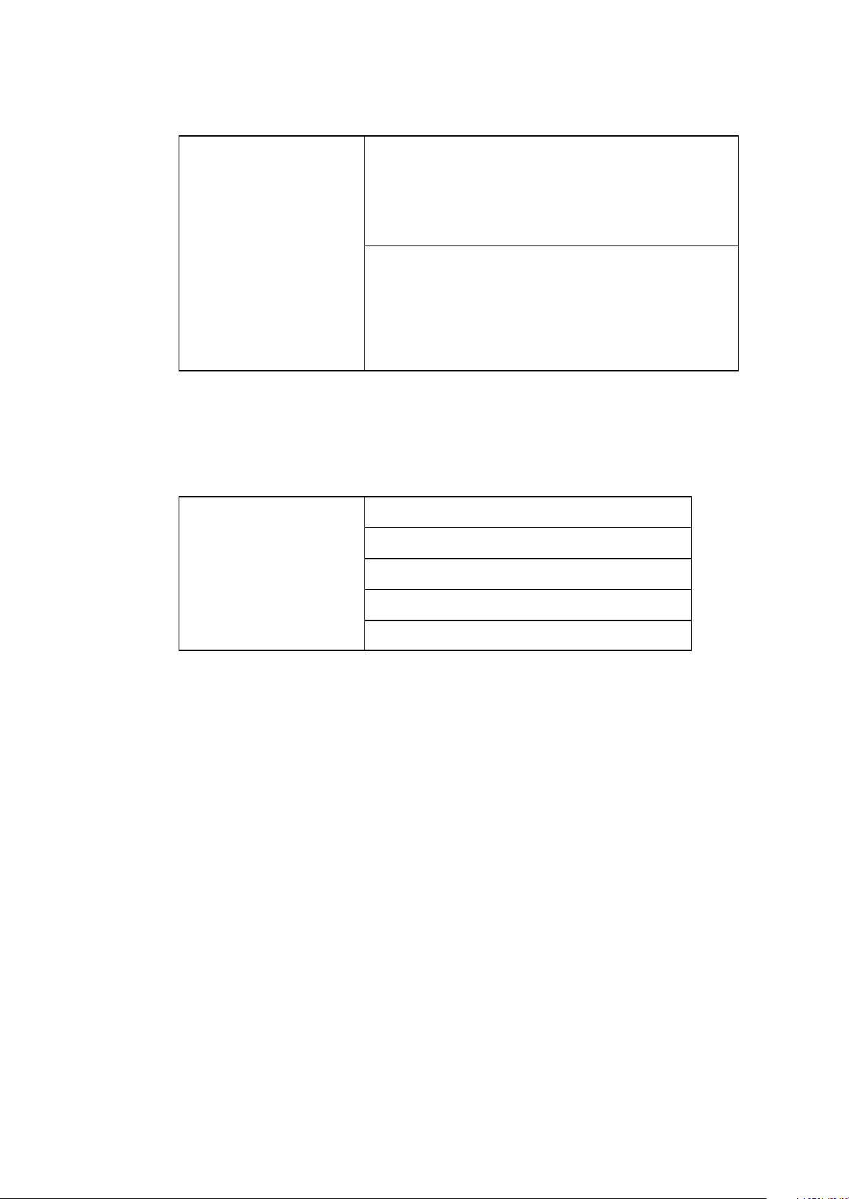
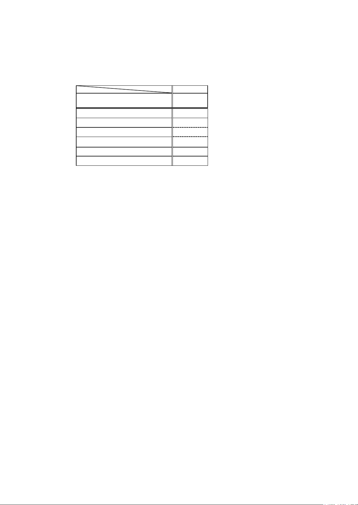
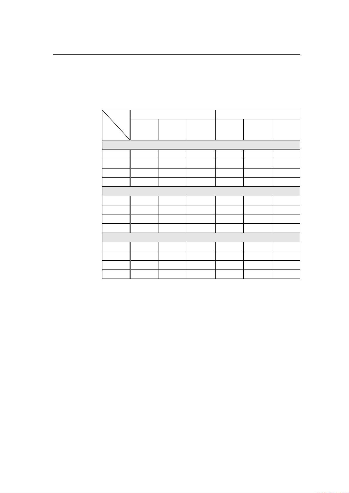
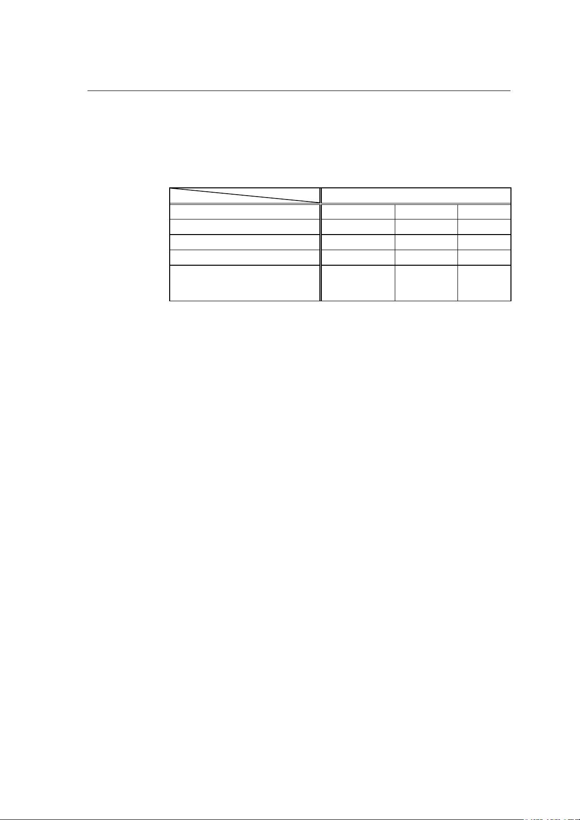
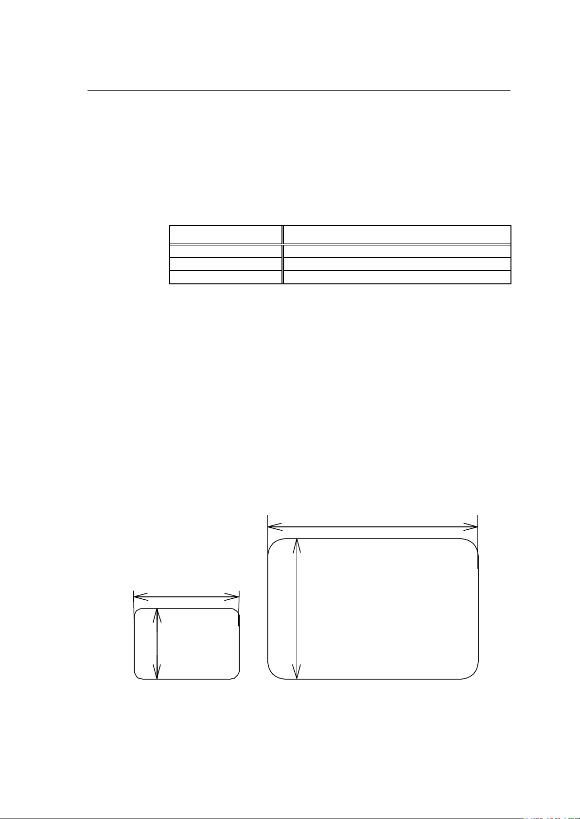
1.4 Outline of Label Format Data
This printer prints label format data by using memory space of the
following size.
Model
area 7206 7106
7010
Reception buffer area [bytes] 16K
Field register data area [bytes] 20K
Number of maximum print fields 400
Global register area [bytes] 1K
Bit map area [bytes] 1892K
Maximum page length [inches] 32
1 Reception buffer area
The reception buffer area is a ring data buffer area (software FIFO)
under software control. Basically, all commands and data transmitted
from the host computer are buffered once into this area and then
executed in the order of buffering to complete communications from
the host computer in the shortest possible time. However, some
system level commands (such as those starting with "SOH" for print
halt) which require real-time execution are executed immediately after
being received.
2 Field register area
A string of character data and bar code data is regarded as one field
that includes information such as type, print position, and size. The
field register area is an area that encloses the label format field. The
label format interpreter analyzes the format data received, stores it
once, and then generates a bit map. If there are any problems in the
data received, the data that is being analyzed is discarded without
being stored in the field register area. The field data is given a control
number for every field (1, 2, · · 400) when the data is stored. This
printer has a field register area of 20,000 characters and can print a
maximum of 400 different types of field data per label.
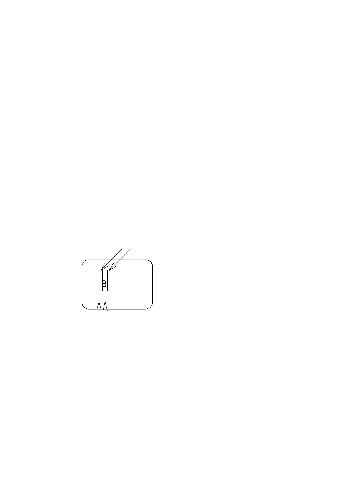
3 Global register area
The global register area is an area which stores field data that is
repeatedly used. A part of the data (character string and bar code
data) in the field register is stored in the global register area and used
as requested. The data stored in the global register area is given a
control number starting with A (A, B, ----- , P). The data set in the
global register is stored while formatting for one label is performed
(until the label format interpreter returns control to the system level
interpreter) so it can be reused for data definition within the same
label.
Page 8

1-6
4 Bit map area
The bit map area is a buffering area for output data. The data in this
area is generated by a rasterizer according to the data in the field
data area and corresponds to individual dots that are generated on
the label during printing. The data of the bit map area is printed on the
label with high quality and at high speed by means of the printer
control program and exclusive thermal control circuit.
Page 9

1-7
1.5 Outline of Label Printing Method
This printer has two label printing methods, one is that all label format
data received is printed, and the other is that format data which has been
received beforehand, is printed or partially modified and printed.
1 All data received method
・ ASCII code "STX" + "L" sets the printer to label format mode.
The printer clears the field register area and control is transferred
from the system level interpreter to the label format interpreter.
At this time, use of label format commands is enabled.
・ Printing data such as characters, bar codes and graphics is
transmitted. Each data set has a special field structure that
includes information such as print position and size. The label
format interpreter, stored in the field register area checks the
printing data received, and generation of bit map data is then
started. Powerful commands such as specification of the number
of copies, characters strings and automatic increasing or
decreasing of bar code data are included in the label format
commands. In addition, the format data stored in the global
register area can be read out and used.
・ After completing label formatting, an ASCII "E" is transmitted.
The printer prints the labels specified by the data in the field
register area and control is then returned from the label format
interpreter to the system level interpreter.
2 Using forma tted data
・ In this mode, fixed format labels are printed. While label data
formatting is completed, an ASCII "X" is transmitted instead of "E."
The printer forms the field register area and completes formatting
without printing and control is returned to the system level
command processor. From this point on, the system level
command processor allows the printer to print fixed format labels
by using the format data in the field register area.
・ If ASCII "STX" + "G" is transmitted to the system level command
processor, the labels are printed according to the contents of the
specified field register.
In addition, change of data and number of copies is provided.
(Only data can be changed. Format information such as print
position and size cannot be changed.) Printing with the "STX" +
"G" command can be performed repeatedly.
Page 10

1-8
1.6 Control Code Specification
1 Outline
・ This printer is connected to the computer via a serial interface and
prints characters and bar codes at the requested print position on
the label.
・ The printer has a data area of 20,000 characters. This character
data can be stored in up to 400 different fields in single buffer
mode (200 different fields in double buffer mode) Each field stores
attributes such as print position, rotation angle, font specification,
and expansion factor (called attribute information). Machine
control commands for print density or printing speed setting are
used in addition to printing data control commands.
・ Basically, this printer prints labels by means of bi-directional
communications with the computer via the serial interface. The
printer not only prints data, but also transmits information such as
label and printer settings to the computer. The computer and
printer communicate so that the printer can receive correct data
from the computer and perform optimum printing.
Also, the printer has the parallel interface (centronics) as a
standard but in this case bi-directional communications are not
used, so data cannot be transmitted from the printer.
Page 11

1-9
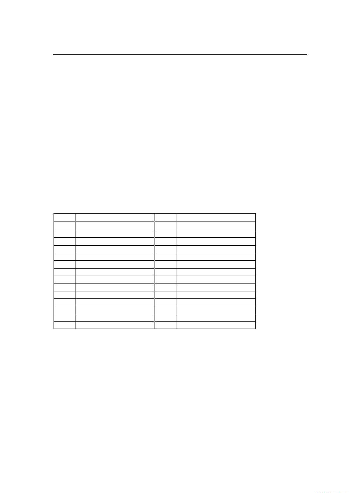
1.6.1 System Level Immediate Execution Commands
These commands are executed as soon as the printer receives them.
They begin with "SOH," i.e. [01].
Command reset [01] #
Printer status transmission request
[01] A
(8-byte packet)
Pause [01] B
Stop/cancel [01] C
SOH command shutdown [01] D
Transmission of number of remaining sheets to be issued [01] E
Printer status transmission request (1-byte packet) [01] F
Error status transmission request
[01] |
(4-byte pack et)
Page 12

1-10
Command reset
250ms).
Code
Function
[01] #
Initialized equivalent to power is turned on. Buffer and on-board
memory contents are initialized. Command setting for previous
commands is initialized.
Transmission
data
Caution
(XOFF) T (XON)
R (XON) for hardware reset.
Since printer executes reset immediately after receiving this
command, it clears un-printed data in the reception buffer. When
using this command, you are recommended to check printing
completion first, then send this command. This com mand will let the
printer off, thus ensure the printer is ready mode state before sending
this command.
Printer status transmission request (8-byte packet)
Code
[01] A
Function If this command is received, printer will send data on current printer
status to the computer with the following 8 ASCII characters.
1
2
3
4
5
6
7
8
Command interpreter in action
Paper end
Ribbon end
Batch processing (printing)
Printing
Pause
Waiting for peeling
Spare
Y or N
Y or N
Y or N
Y or N
Y or N
Y or N
Y or N
N (always)
After sending 8 ASCII characters, code [0D] hex is added. Y and N
each is hex digit and [59] hex and [4E] hex.
Caution
Printer sends data on printer status to the computer as soon as it
receives this command (in a period of approx. 150ms Therefore, the computer must be ready to receive data from the
printer immediately after receiving this command.
Page 13

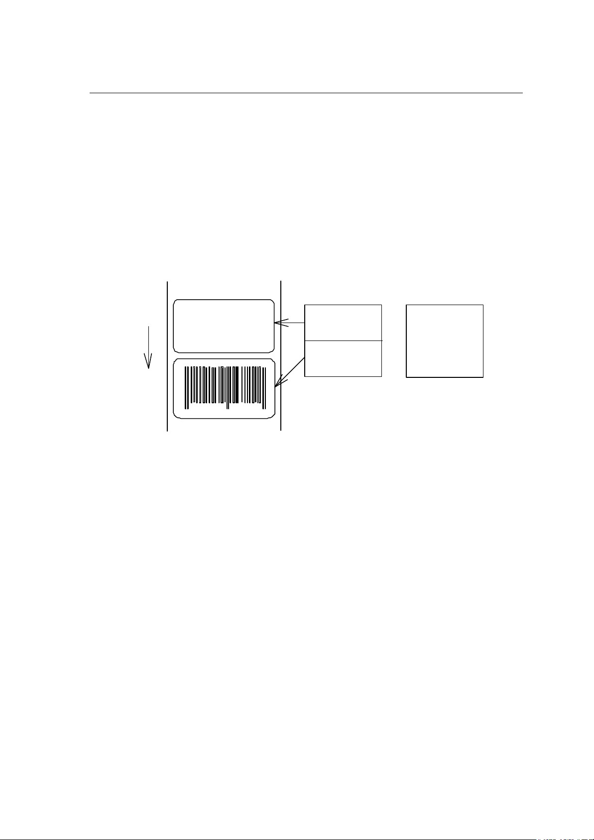
1-11
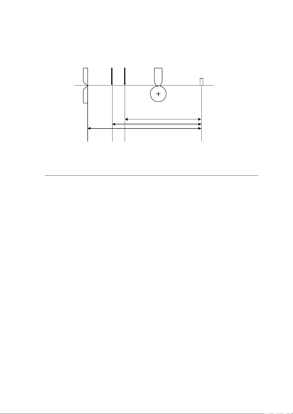
Printer status
Relationship between command interpreter, batch processing and printing
Normal label printing puts the printer in the above status. The printer, however,
operates with a double buffer, so if the next printing data is received during batch
processing, both interpreter operation and batch processing (printing) may be
performed simultaneously.
Difference between batch processing and printing
As shown in the diagram, printing start and stop may be repeated within a single
cycle of batch processing. Therefore, use the operations properly (peeling,
auto-cutter, etc.) as required.
Pause
Code
Function
[01] B
Printing temporarily stops and resumes. Toggles printer pause on and
off. Pause on and off by using this command is performed in the same
way as operated from the control panel. Pause on from the control
panel can change to pause off with this command.
Stop/cancel
Code
Function
[01] C
Printing stops. Performed in the same way as operated from the Stop
key on the control panel. With this command, printer stops on
completion of the current printing label and will clear data in the
reception buffer.
SOH command shutdown
Code
Function
[01] D
After receiving this command, printer ignores immediate execution
commands starting with control code [01] even if those commands are
received.
To send nothing for five seconds can automatically cancel the setting.
Page 14

1-12
Transmission of number of remaining sheets to be issued
Code
Function
[01] E
If this command is received, printer will send data on the number of
remaining sheets to be issued for the current printing to the computer
with 4 ASCII characters.
The [0D] hex code is added to the end of the 4-digit transmission data.
Caution
Printer sends data on the number of remaining sheets to be issued to
the computer as soon as it receives this command (in a period of
approx. 150ms - 250ms). Therefore, the computer must be ready to
receive data from the printer immediately after receiving this
command.
Printer status transmission request (1-byte packet)
Code
Function
[01] F
If this command is received, printer will send 1-byte packet data on
current printer status to the computer. The contents of 1-byte packet
data transmitting from the printer are as follows:
Caution
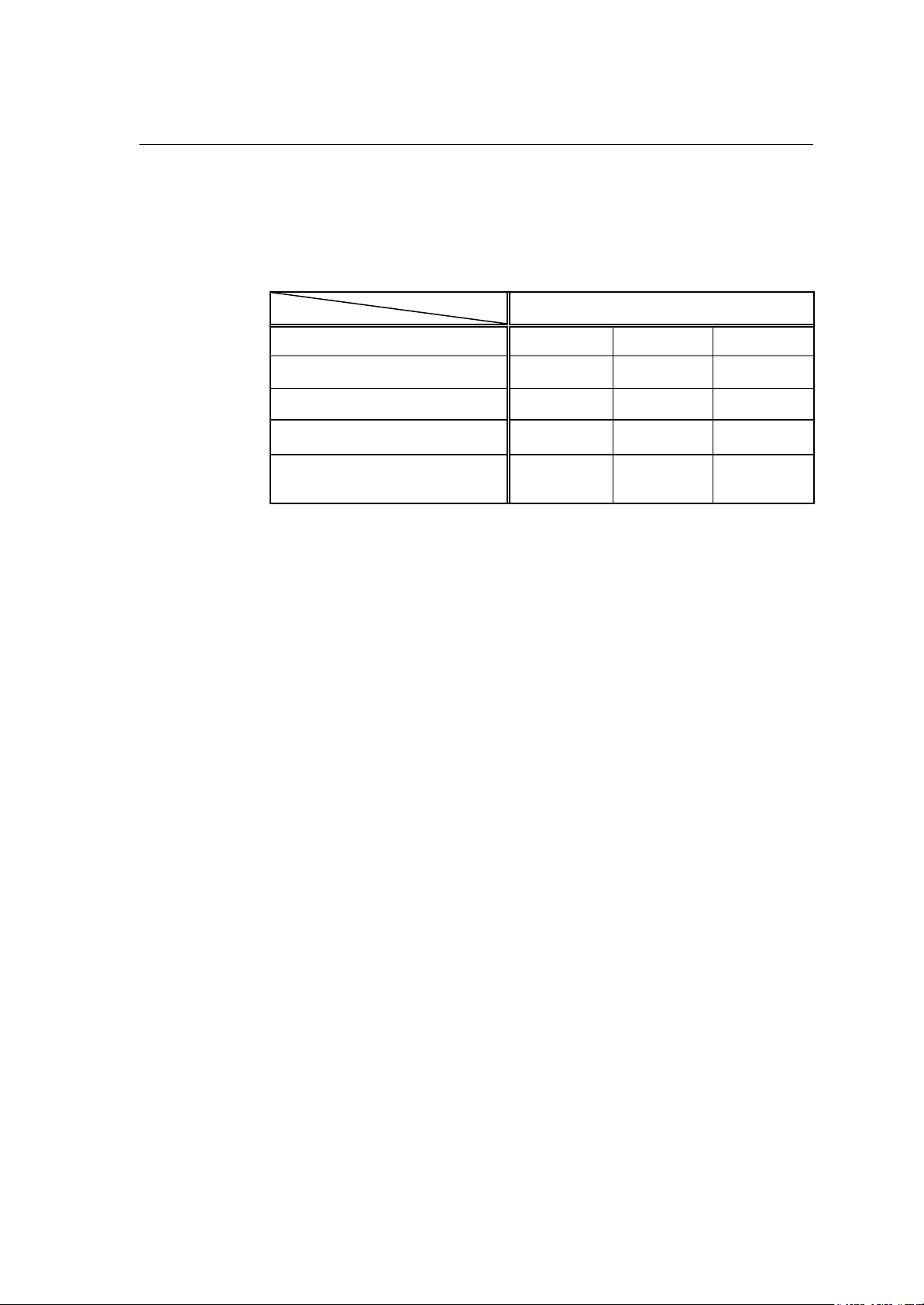
Bit
1
2
3
4
5
6
7
8
Description
Command interpreter in action
Paper end
Ribbon end
Batch processing (printing)
Printing
Pause
Waiting for peeling
Spare
YES NO
1 or 0
1 or 0
1 or 0
1 or 0
1 or 0
1 or 0
1 or 0
0
(always)
The [0D] hex code is added to the end of transmission data.
Printer sends data on printer status to the computer as soon as it
receives this command. Therefore, the computer must be ready to
receive data from the printer immediately after receiving this
command.
Page 15

1-13
Error status transmission request (4-byte packet)
Code
Function
[01] I
After receiving this command, printer sends 4-byte data on current
conditions inside the printer to the host PC. Shown below are contents
of the 4-byte data to be sent from the printer.
Byte
1
2 1
3 1
4 1
Bit
Description
1
Battery exhaustion (Unsupported)
2
Head at low temperature (Unsupported)
3
Main PCB at low temperature (Unsupported)
4
Wear and tear on a head
5
Spare
6
Pause
7
Fixed
8
Fixed
Spare
2
Head overheat
3
Spare
4
Spare
5
Mechanism is exposed.
6
Paper end
7
Fixed
8
Fixed
Paper out
2
Ribbon end
3
Overheating of Main PCB (Unsupported)
4
Spare
5
Abnormality in option boards (Unsupported)
6
Abnormality in auto cutter
7
Fixed
8
Fixed
Fan motor stop (Unsupported)
2
Spare
3
Spare
4
Spare
5
Spare
6
Error is occurring.
7
Fixed
8
Fixed
YES NO
1 or 0
1 or 0
1 or 0
1 or 0
0 (always)
1 or 0
1 (always)
0 (always)
0 (always)
1 or 0
0 (always)
0 (always)
1 or 0
1 or 0
1 (always)
0 (always)
1 or 0
1 or 0
1 or 0
0 (always)
1 or 0
1 or 0
1 (always)
0 (always)
1 or 0
0 (always)
0 (always)
0 (always)
0 (always)
1 or 0
1 (always)
0 (always)
The [0D] hex code is added to the end of transmission data.
Caution
Printer sends data on printer status to the computer as soon as it receives this
command. Therefore, the computer must be ready to receive data from the
printer immediately after receiving this command.
Page 16

1-14
1.6.2 System Level Occasional Execution Commands
These commands are executed as soon as the printer receives them.
They begin with "STX," i.e. [02].
Setting date and time [02] A
Setting feedback character transmission validness [02] a
Date and time transmission request [02] B
Setting paper length for continuous paper [02] c
Setting two -page edit mode (double buffer) [02] d
Changing number of prints for edited format [02] E
Setting edge sensor selection [02] e
Label one sheet feed [02] F
Setting peeling (cutting) position [02] f
Printing edited or formerly-printed format [02] G
Graphics data block input command [02] I
TrueType fonts downloading command [02] i
Pause per label printing [02] J
Extension system command (printer settings) [02] KD
Extension system command (setting peeling or cutting position) [02] Kf
Setting Y-code-transmission-to-serial-port request [02] k
Specifying printing contents setting start [02] L
Setting maximum label length [02] M
Changing units from inch to metric system [02] m
Changing units from metric to inch system [02] n
Setting printing position [02] O
Paper cut [02] o
Setting dump mode start [02] P
Pause in occasional execution [02] p
Clearing all memory module contents [02] Q
Clearing memory module contents [02] q
Setting reflective paper sensor selection [02] r
Setting paper feed speed [02] S
Setting one-page edit mode (single buffer) [02] s
Page 17

1-15
Printing quality test pattern [02] T
Rewriting specified format register contents [02] U
Setting memory switch contents [02] V
Printer version numb er transmission request [02] v
Information-in-memory-module transmission request [02] W
Testing flash memory [02] w
Default module selection [02] X
Clearing memory module contents (in file units) [02] x
TrueType fonts Symbol Set Selection [02] y
Printing printer status [02] Z
Select Command Set [02][1B] G
Setting printing methods [02][1B] M
Head disconnection detection [02][1B] T
Setting ejection (tear-off) [02][1B] t
Setting label width [02][1B] w
Page 18

1-16
Setting date and time
4
Code
Setting
[02] A, w, mm, dd, yyyy, hh, MM, j j j
w Sun. 0 Mon. 1 Tues. 2 Weds. 3 Thurs.
Fri. 5 Sat. 6
mm Month 01 - 12
dd Day 01 - 31
yyyy Year 4 digits
hh Hour (24-hour display)
MM Minute 00 - 59
j j j Spare 000 fixed
Function
Example
Input data
Sets date and time on the calendar stored in the printer.
Input data below represents 15:30 Saturday 7 July 2001.
[02]A607072001 1530000
Setting feedback character transmission validness
Code
Function
Caution
[02] a
With this command, printer transmits [1E] every one label printing to
the computer and on completion of one batch printing, [1F] is
transmitted to the computer.
After one label printing [1E]
On completion of one batch printing [1F]
When receiving invalid label format command [07]
The [0D] hex code is not added to the end of the transmission data.
Page 19
1-17
Date and time transmission request
4
(c0250)
Code
Data format
Function
Example
[02] B
w, mm, dd, yyyy, hh, MM, j j j
w Sun. 0 Mon. 1 Tues. 2 Weds. 3 Thurs.
Fri. 5 Sat. 6
mm Month 01 - 12
dd Day 01 - 31
yyyy Year 4 digits
hh Hour (24-hour display)
MM Minute 00 - 59
j j j Total number of days from the 1st of January
Data on the contents of the calendar (date and time) stored in the
printer is transmitted to the computer. Data format transmitted from
the printer is described below. The [0D] hex code is added to the end
of the transmission data.
Reception data below represents 15:30 Saturday 7 July 2001, which is
transmitted from the printer.
Reception
data
6070720011530188[0D]
Direction of feed
901234 567894
4
Paper length
2.5 in
Page 20
1-18
Setting paper length for continuous paper
(c0250)
Code
Unit
Setting
Function
Example
Input data
[02] c nnnn
0.01 inch
nnnn 4-digit data Initialization value: 0000
Inch system 0001 – 9999 (0.01 – 99.99 inches)
Metric system 0001 – 9999 (0.1 – 999.9 mm)
Sets label length for continuous paper. Length of label format is
specified with this command. Label is cut in the length with this setting
when using auto-cutter. When using label paper, 0000 must be set.
Example of input data below represents paper length of 2.5-inch
setting.
[02] n Sets units to inch system
[02] c 0250 Sets paper length to 2.5 inches
for continuous paper
[02] L Starts label format mode
D11 Sets pixel size
1F3306000500050490123456789 Sets EAN13 bar code for data
E Ends label format mode and
Direction of feed
901234 567894
4
"490123456789"
prints
Paper length
2.5 in
Page 21
1-19
Setting two-page edit mode (double buffer)
901234
Code
Function
Caution
Direction of feed
[02] d
After receiving this command, printer divides the internal edit
buffer into 2 pages and enters the high-speed edit mode.
In the high-speed edit mode, editing the next page in advance while
the current page is being printed increases printing speed.
The printer automatically judges whether the double buffer is needed
or not, and the mode is switched accordingly, so this command does
not need to be particularly specified. Maximum printing length per
page is 40 inches, independently of the division.
Internal edit buffer
One-page mode
1st page
In one-page mode,
until printing is completed
ABCD
Two-page mode
2nd page
1st page
In two-page mode,
data on next page is edited
while printing 1st page
Page 22
1-20
Changing number of prints for edited format
three sheets are printed with
Code
Setting
Function
Example
Input data
[02] E nnnn
nnnn 4-digit numeric 0001 - 9999
Specifies changing of number of prints for formatted or formerly
printed label format.
Input data below represents that after ending label format printing data
"ABC" one sheet, the number of prints is set to 3 by using this
command and printing is executed with [02] G command. (In this case,
the number of prints is one plus three.)
[02] n Sets units to inch system
[02] L Starts label format mode
D22 Sets pixel size
190001001000050ABC Sets character data "ABC" with smooth
font 48pt
E Ends label format mode and prints
[02] E0003 Sets 3-sheet printing for edited format
[02] G Executes 3-sheet printing for edited
format
Direction of feed
After changing number of prints to 3,
ABC
ABC
ABC
One sheet is printed with "E"
"G"
ABC
Page 23
1-21
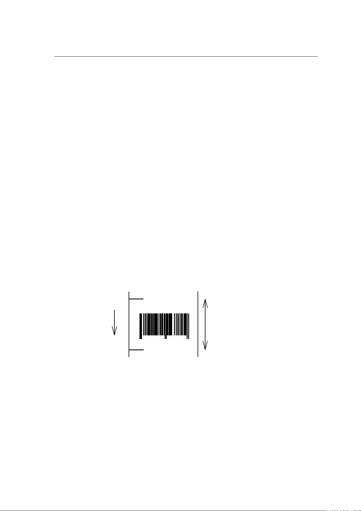
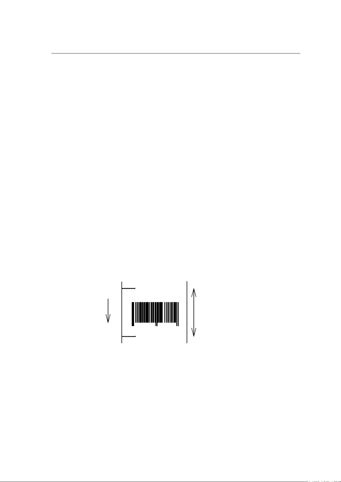
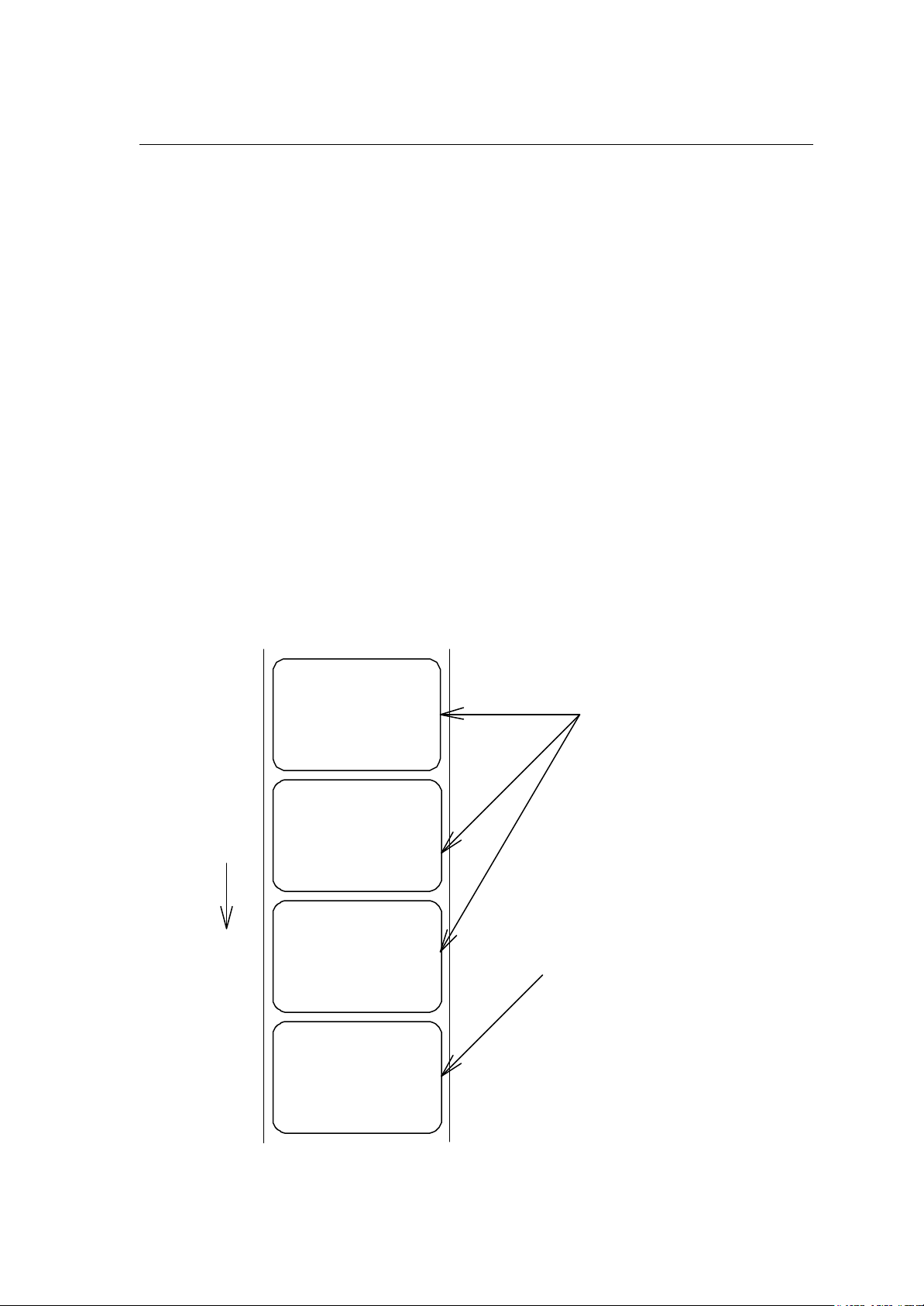
Setting edge sensor selection
ABCDEF
ABCDEF
Label paper
Code
Function
Caution
Example
[02] e
Changes paper position detection sensor to transparent-type.
Used for detecting paper gap between label papers, die-cut paper,
notch hole for tag paper, etc. This setting is used as default.
If not detected properly, check the sensor position.
Paper gap between label papers and notch holes for tag paper in Fig
below is detected.
Label paper gap
No 0001
No 0002
Tag paper notch holes
Label one sheet feed
Code
Function
[02] F
Feeds label one sheet. The amount of feed is the length from the
bottom of the label paper to the next bottom of the label paper.
When using continuous paper, feeds paper the length currently set
([02] c nnnn).
Performed in the same way as operated from the Feed key on the
control panel.
Direction of feed
Continuous paper
Amount of feed Paper length
[02] cnnnn
Page 24
1-22
Setting peeling (cutting) position
Code
Units
Setting
[02] f nnn
0.01 inch (0.1mm)
nnn 3-digit data
Initial value and its set range vary depending on the command setting.
Inch system Metric system
Initial
value
DMI / DMW
Normal
Cutter
Peel
Tear Off
DM4 / DM8
Normal
Cutter
Peel
Tear Off
DPP
Normal
Cutter
Peel
Tear Off
*In setting 4-digit value, use [02] Kf command.
000 000 200 000 000 508
100 000 200 254 000 508
050 000 150 127 000 381
070 000 170 178 000 432
220 220 420 559 559 1067*
340 240 440 864 610 1118*
270 220 370 686 559 940
290 220 390 737 559 991
110 110 310 279 279 787
230 130 330 584 330 838
146 96 246 371 244 625
166 96 266 422 244 676
Minimum
value
Max
value
Initial
value
Minimum
value
Max
value
Function
Caution
With the setting above, the distance between paper sensor and
cutter or peeler can be specified.
When nnn is small, the amount of feed is small, so printed label will
be cut.
When nnn is appropriate, the label is fed the required amount, then
cut at the paper gap.
When nnn is large, the amount of feed is large, so the next printing
label will be cut.
If value out of range is specified, the command parameter will be
ignored.
If optional functions such as cutter, peeler and ejection are turned
on from the control panel, their initialization values will be set
automatically. These initialization values, however, vary depending
on the specifications of each option. For details, see the instruction
manuals of each option.
Once this command was set, auto-setting function is stopped due to
priority for user's specification. Do not set this command if not
necessary.
Page 25
1-23
Figure
Print head
Cutter
Ejection
Note: Peeler option is not available for CLP-8301
Peeler
Printing edited or formerly-printed format
Code
Function
[02] G
Prints label data for former printing or formatting.
Paper sensor
A
B
C
Caution
Example
Input data
This command is effective only when label data for former printing or
formatting is left in the internal memory. If power is turned off or reset
is performed, data in the internal memory will be cleared, so this
command will not be effective.
Input data below represents that after ending label format printing data
"ABC" one sheet, printing for the same data is executed again with
this command [02] G.
[02] n Sets units to inch system
[02] L Starts label format mode
D22 Sets pixel size
190001001000050ABC Sets character data "ABC" with smooth
font 48pt
E Ends label format mode and prints
[02] G Executes 1-sheet printing for edited
format
Page 26
1-24
Graphics data block input command
Code
Transmission
data
[02] I m a f name, data
m Storing memory module specification
Allocation of modules varies with command settings. Refer to the table
below.
Command Set
Allocation of module DMI / DMW DM4 / DM8
on-board SD-RAM D A B
on-board flash memory G B A
PCMCIA Card (option) E or F E or F E or F
Current memory module on-board
SD-RAM
on-board
SD-RAM
DPP
on-board
SD-RAM
f Graphics data format
F 7-bit image loading file
I 8-bit image format (image saved in reverse)
i 8-bit image format (image saved in normal)
B 8-bit BMP format (saved in normal)
Function
Caution
b 8-bit BMP format (saved in reverse)
P 8-bit PCX format (saved in normal)
p 8-bit PCX format (saved in reverse)
Note: For graphics data format, refer to input data examples.
name File name for graphics data (up to 16 characters ending
with CR)
data Graphics data for each format
Stores specified format data in the specified memory module.
In the 8-bit BMP format and PCX format, data in colors other than
black-and-white (two colors) cannot be used. Color or gray-scale data
must be converted to black -and-white before use.
If the same file name as that of the current file is used for storing its
data in the memory module, the contents of the current file will be
replaced by the new image file. (Note: Working memory space is
required for new image file.) Therefore, if overwrite is repeated, the
data will not be stored due to lack of memory capacity. In this case,
packing the data with command [02] z may store the data in the
memory module.
Page 27

1-25
7-bit image loading file format
7-bit image data uses ASCII format data. In this example, 7-bit image data with the file
name of “MARK7” is stored in the memory card and printed out. Value of inside [ ] is
shown in hex format.
[02]IBFMARK7 --------------- Graphics data input command
8006000041040000 ---------- After this, 7-bit image data follows
80060000C30C0000 Top data “80” is a starting code for image data
8006000186180000 Next data “06” following “80” is the number of data in
800600030C300000 horizontal direction
800600071C700000
8006000618600000
8006000618600000
8006000618600000
8006000618600000
800600030C300000
800600030C300000
8006000186180000
80060001C71C0000
80060000C30C0000
80060000C30C0000
80060000C30C0000
80060030C30CC000
800600F18618F000
800603E186187C00
800607830C301E00
8006070F3CF00E00
80060E1E79E00700
80060C3861800300
80061C0000000380
80061C0000000380
80060C0000000300
80060E0000000700
8006070000000E00
8006078000001E00
800603E000007C00
800601F80001F800
800600FC0007F000
8006003F803FC000
8006000FFFFF0000
80060003FFFC0000
800600007FE00000
FFFF ------------------------------------ Graphics data ending code
[02] m
[02] M1500 ---------------------------- Sets maximum label length
[02] L ------------------------------------ Starts label format
D22
1Y1100001000500MARK7 -------- Develops “ MARK7” graphics data to specified position
E ----------------------------------------- Starts printing
Page 28

1-26
8-bit image format
Data on header is fixed except
After this, 8
-
bit image data follows
8-bit image data uses ASCII format data. In this example, 8-bit image data with the
file name of “MARK8” is stored in the memory card and printed out. Value of inside
[ ] is shown in hex format. (Note: Data below is described in hex.)
[01][44][0D]--------------------------- Stops immediate execution command
(Required only for 8-bit image data)
[02][49][42][69][4D][41][52][4B][38][0D]----------- Graphics
[00][01][00][08][00][01][00][02][00][7F][00][7F][00][E0][00][24] ----------┐
[80][06][00][00][41][04][00][00] -----[80][06][00][00][C3][0C][00][00]
[80][06][00][01][86][18][00][00]
[80][06][00][03][0C][30][00][00]
[80][06][00][07][1C][70][00][00]
[80][06][00][06][18][60][00][00]
[80][06][00][06][18][60][00][00]
[80][06][00][06][18][60][00][00]
[80][06][00][06][18][60][00][00]
[80][06][00][03][0C][30][00][00]
[80][06][00][03][0C][30][00][00]
[80][06][00][01][86][18][00][00]
[80][06][00][01][C7][1C][00][00]
[80][06][00][00][C3][0C][00][00]
[80][06][00][00][C3][0C][00][00]
[80][06][00][00][C3][0C][00][00]
[80][06][00][30][C3][0C][C0][00]
[80][06][00][F1][86][18][F0][00]
[80][06][03][E1][86][18][7C][00]
[80][06][07][83][0C][30][1E][00]
[80][06][07][0F][3C][F0][0E][00]
[80][06][0E][1E][79][E0][07][00]
[80][06][0C][38][61][80][03][00]
[80][06][1C][00][00][00][03][80]
[80][06][1C][00][00][00][03][80]
[80][06][0C][00][00][00][03][00]
[80][06][0E][00][00][00][07][00]
[80][06][07][00][00][00][0E][00]
[80][06][07][80][00][00][1E][00]
[80][06][03][E0][00][00][7C][00]
[80][06][01][F8][00][01][F8][00]
[80][06][00][FC][00][07][F0][00]
[80][06][00][3F][80][3F][C0][00]
[80][06][00][0F][FF][FF][00][00]
[80][06][00][03][FF][FC][00][00]
[80][06][00][00][7F][E0][00][00]
[46][46][46][46] ------------------------- Graphics data ending code
[02] m [0D]
[02] M1500 [0D]------------------------- Sets maximum label length
[02] L [0D] ------------------------------- Starts label format
1Y1100001000500MARK8[0D]----- Develops “ MARK8” graphics data to specified position
Top data “80” is a starting code for
image data
Next data “06” following “80” is the
number of data in horizontal direction
for the last 2 bytes, i.e., “00”
“24”(36 lines in this example)
E [0D] ------------------------------------- Starts printing
Page 29
1-27
Download of TrueType Font
Code
Transmission
data
[02] i m T nn name <CR> xxxxxxxx data…
m Storing memory module specification
Allocation of modules varies with command settings. Refer to
the table below.
Command Set
Allocation of module DMI / DMW DM4 / DM8
on-board SD-RAM D A B
on-board flash memory G B A
PCMCIA Card (option) E or F E or F E or F
Current memory module on-board
SD-RAM
on-board
SD-RAM
DPP
on-board
SD-RAM
T T fixed (TrueType)
nn Two-digit font ID
Valid values: 50 – 59, 5A – 5Z, 5a – 5z,
60 – 69, 6A – 6Z, 6a – 6z,
Function
Caution
Example
Input data
:
90 –99, 9A – 9Z, 9a – 9z
name Font name (Max. 16 characters followed by CR code to end)
xxxxxxxx TrueType font data size, number of bytes assigned by 8
digits hexadecimal characters.
data TrueType font data
Stores specified font data in the specified memory module.
File will be overwritten when the font data is stored in the memory
module using the same name of the existing file. Therefore, free
space for the file to write new data will be necessary.
The following command line shows the command to download 34754
bytes of TrueType font file, named “Tree Frog”, with the font ID 52 into
the memory module B:
[02] iCT52TreeFrog<CR>000087C2 data…
Page 30

1-28
Pause per label printing
Code
Function
Caution
[02] J
Performs pause each time label is printed one sheet. Used when label
peeling detection sensor is not mounted on the printer incorporating
peeling function. Pause is cancelled by pressing Pause key on the
control panel.
To clear this function, reset the printer.
Page 31

1-29
Extension system command (printer settings)
Code
Transmission
data
[02] Kdabc
Printer setting parameter
a Hex notation for the following bit settings
bit 0-2 baud rate
case bit 4 = 0
0=9600*, 1=600, 2=2400, 3=4800, 5=300,
6=1200, 7=9600 test mode
case bit 4 = 1
0=115200, 1=57600, 2= 38400, 3= none, 5=none,
6= none 7= none
bit 3 character length
0=8 bits*, 1=7 bits
bit 4 Extended baud rate
0=OFF*, 1=ON
bit 5 (not used) always 0
bit 6 (fixed) always 1
bit 7 (fixed) always 0
b Hex notation for the following bit settings
bit 0 printing method
0=thermal, 1=thermal transfer*
bit 1 peeling sensor
0=OFF*, 1=ON
bit 2 (not used) always 0
bit 3 auto-cutter
0=OFF*, 1=ON
bit 4-5 (not used) always 0
bit 6 (fixed) always 1
bit 7 (fixed) always 0
c Hex notation for the following bit settings
bit 0-1 type of paper
0=transparent*, 1=reflective, 2=continuous (3 inches)
bit 2-5 (not used) always 0
bit 6 (fixed) always 1
bit 7 (fixed) always 0
Function
Caution
Example
(*: factory setting)
Provides various printer settings.
This setting is stored even when the power is turned off.
[02]KD@A@[0D]
@: 9600 baud, 8-bit length, no parity
A: thermal, no peeling sensor, no auto-cutter
@: transparent paper
[02]KDP@B[0D]
Page 32

1-30
P: 115200 baud, 8-bit length, no parity
@: thermal transfer , no peeling sensor, no auto-cutter
B: continuous paper
Setting peeling (cutting) position
Code
Units
Setting
[02] Kf nnnn
0.01 inch (0.1mm)
nnnn 4-digit data
Inch system 0001 - 9999 (0.01 – 99.99 inches)
Metric system 0001 - 9999 (0.1 – 999.9 mm)
Function/
Command is valid only for DMI/DMW mode.
Caution
It has the same funct ion as that of [02] fnnn.
For details, refer to [02] fnnn command.
Setting Y-code-transmission-to-serial-port request
Code
Function
Caution
[02] k
After receiving this command, printer issues "Y"(59hex) code via serial
port. This allows printer and computer to synchronize each other.
[0D] hex code is not added to the end of the "Y"(59hex) code.
Page 33

1-31
Specifying printing contents setting start
Code
Function
Example
Input data
[02] L
With this command input, printer enters the label format mode and
waits for input of printing contents definition and label format
commands until it receives "E" "s" or "X" code.
Input data below represents that label format command input is
started, data "ABC" is defined as printing contents, label format
command input is completed, and label printing command "E" is
entered.
[02] n Sets units to inch
[02] L Starts label format mode
D22 Sets pixel size
190001001000050ABC Sets character data "ABC" with smooth
font 48pt
E Ends label format mode and prints
Direction of feed
ABC
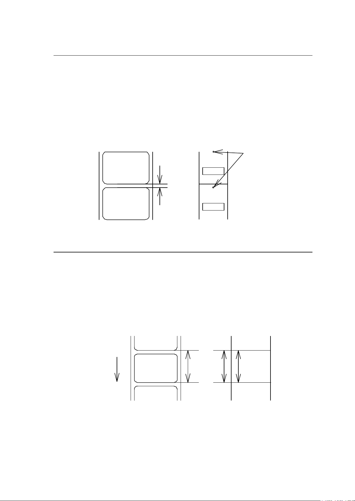
Page 34

1-32
Setting maximum label length
901234
Code [02] M nnnn
Units 0.01 inch or 0.1 mm
Setting nnnn 4-digit data Initialization value: 1000 (10.00 inches)
Max. value: Inch system 9999 (99.99 inches)
Metric system 9999 (99.9 mm)
Function
Sets maximum label length for detecting label out. If printer cannot
detect the next top of the label within the maximum label length which
has been set with this command, "M" command error occurs. Set
value 2.5 to 3 times as large as the label length to be used.
Example
I f label length is 2.5 inches, the value more than double 2.5 inches
must be set for maximum label length. But if label length is 1.1 inch or
less, the value more than triple must be set for maximum label length.
Input data below is for 3.5-inch setting
Input data
[02] n Sets units to inch system
[02] M 0350 Sets 3.5 inches for maximum
label length
[02] L Starts label format mode
D11 Sets pixel size
1F3306000500050490123456789 Sets EAN13 bar code for data
"490123456789"
E Ends label format mode and
prints
Initialization value for printer maximum label length is set to 10 inches (254 mm). If
longer label length is required, using the maximum label length command must set the
value larger than the length of printing. If the length of printing is larger than the
maximum label length, set the M command as follows:
Maximum label length [02] M nnnn > length of printing
Note: If label paper mode is continuous paper, this command is ignored.
Direction of feed
Label length
Maximum label length
Page 35

1-33
Changing units from inch to metric system
When inch is specified
5 mm
(0050)
Code
Function
Example
Input data
Printing results of the same data with or without units of metric system are as follows:
Changing units from metric to inch system
[02] m
Changes units for all-distance-specified-command-parameters from
0.01 inch to 0.1 mm. With reset, units are set to metric syst em.
Input data below represents that data "ABC" is specified with units in
metric system.
[02] m Sets units to metric system
[02] L Starts label format mode
D22 Sets pixel size
190001001000050ABC Sets character data "ABC" with smooth
font 48pt
E Ends label format mode and prints
Code
Function
Example
Input data
Direction of feed
[02] n
Changes units for all-distance-specified-command-parameters from
0.1 mm to 0.01 inch. With reset, units are set to inch system.
Input data below represents that data "ABC" is specified with units of
inch.
[02] n Sets units to inch
[02] L Starts label format mode
D22 Sets pixel size
190001001000050ABC Sets character data "ABC" with smooth
font 48pt
E Ends label format mode and prints
When mm is specified
ABC
1 inch
(0100)
ABC
10 mm
(0100)
0.5 inch
(0050)
Page 36

1-34
Setting printing position
Code
Units
Setting
Function
Caution
Figure
[02] O nnnn
0.01 inch or 0.1 mm
nnnn 4-digit data
I nitial value and its set range vary depending on the command set.
Inch system Metric system
Command Set
DMI / DMW 0220 0120 0320 0559 0305 0813
DM4 / DM8 0220 0120 0320 0559 0305 0813
DPP 0110 0010 0210 0279 0025 0533
Initial
value
Minimum
value
Max
value
Initial
value
Minimum
value
Max
value
Specifies the distance between paper sensor and print head. By
changing this value, a physical printing start position can be changed.
If value less than 0.5 inch (0050) is specified, the initialization value will
be set automatically. With the initialization value set, printing starts from
the bottom of the label. If the command is used after completing
printing, this command setting will not be effective to the first sheet of
the label. From the second sheet of the label, this will be effective.
Cutter
Peeler
Print head Reference point
(peeling)
Onnnn = 1.10 inch (initialization value)
Page 37

1-35
Paper cut
all data transmitted from the computer are printed out with hex code.
Code
Function
Caution
[02] o
When mounting auto-cutter, if this command is received, the label or
paper cutting will be performed once.
If auto-cutter is not turned to ON, this command will be ignored.
Set the cutting sheet number to 0 (zero) with the specified command
(cnn or :nnnn). Otherwise, each label will be cut automatically.
Setting dump mode start
Code
Function
Example
[02] P
By receiving this command, printer enters the dump mode. After that,
To escape from the dump mode, turn on and off the power or turn the
“Hex Dump” mode off by the operation panel.
Input data below represents that label format command input is
started, data "ABC" is defined as printing contents, label format
command input is completed, and label printing command "E" is
entered.
Input data
Direction of feed
[02] P Sets dump mode
[02] L Starts label format mode
190001001000050ABC Sets character data "ABC" with smooth
font 48pt
E Ends label format mode and prints
DUMP LIST
0D024C0D4431310D3139313130313030..L.D11.19110100
313030303035304142430D450D 1000050ABC.E.
Page 38

1-36
Pause in occasional execution
Clearing of all memory module contents takes about 15 seconds.
Code
Function
Caution
[02] p
Executes pause occasionally.
Pause on and off cannot be performed with this command. Cancelling
pause must be operated from the Pause key on the control panel.
Clearing all memory module contents
Code
Function
[02] Q
Clears all data in on-board flash memory and on-board SD-RAM and
option memory card modules.
Caution
For models with an LCD, "On Line" appears on the LCD as soon as
the module contents are cleared.
Page 39

1-37
Clearing memory module contents
memory module takes about 10 seconds.
Code
Setting
Function
Caution
[02] q n
n Memory module specification parameter
Allocation of modules varies with command settings. Refer to the
table below.
Allocation of
module
on-board SD-RAM
on-board flash
memory
PCMCIA Card
(option)
Current memory
module
DMI / DMW DM4 / DM8 DPP
D A B
G B A
E or F E or F E or F
on-board
SD-RAM
Command Set
on-board
SD-RAM
on-board
SD-RAM
Clears all data in memory module.
Clearing of on-board flash
For models with LCD, "On Line" appears on the LCD as soon as the
module contents are cleared.
Input data
[02] q B Sets clearance of module B (on-board SD-RAM ) contents.
Page 40

1-38
Setting reflective paper sensor selection
Detects label position automatically by reflective paper sensor.
Black line
Code
Function
Caution
Example
[02] r
Reflective paper sensor detects black lines that are printed on the
back of the label and understands the label position. In default,
reflective paper sensor is selected.
When detection is not performed properly, check the sensor position.
As shown in the figure below, label position is detected with the black
lines on the back of the label.
Black line
Label paper gap
Direction of feed
Black line
* Figure above shows the back of the paper
Page 41

1-39
Setting paper feed speed
and maximum value vary depending on the printer
*Feeds at speed of setting Sa (or previous
(or previous
(or previous paper
Paper feed area
Code
Setting
[02] Sa
a Paper feed speed specifying character
A or B or 1 2.0 inches (50.8 mm)/sec
C or D or 2 2.0 inches (50.8 mm)/sec
E or F or 3 3.0 inches (76.2 mm)/sec
G or H or 4 4.0 inches (101.6 mm)/sec
I or J or 5 5.0 inches (127.0 mm)/sec
K or L or 6 6.0 inches (152.4 mm)/sec
M or N or 7 7.0 inches (177.8 mm)/sec
O or P or 8 8.0 inches (203.2 mm)/sec
Q or R or 9 9.0 inches (228.6 mm)/sec
S or T or a 10.0 inches (254.0 mm)/sec
U or V or b 11 .0 inches (279.4 mm)/sec
W or c 12.0 inches (304.5 mm)/sec
Note: Initial value
model.
Function
Direction of feed
Sets paper feed speed.
Paper feed area
Unprintable area*
Printable area
Unprintable area*
Unprintable area
Power is turned on
Feeds at speed of setting STX+Sa
(of default value)
paper feed section when no Sa is set
Feeds at speed of setting Pa (or default value)
Feeds at speed of setting STX+Sa
unprintable section when no STX + Sa is set)
Feeds at speed of setting Sa
feed section when no Sa is set
Page 42

1-40
Setting one-page edit mode (single buffer)
Code
Function
[02] s
After receiving this command, printer makes the internal edit buffer
one page. At this time, the maximum printing length on one page is 40
inches. In initialization after turning on power, this mode is set.
Caution
The printer automatically judges whether the single buffer is needed or
not, and the mode is switched accordingly, so this command does not
need to be particularly specified. Maximum printing length per page is
40 inches.
Printing quality test pattern
Code
Function
[02] T
After receiving this command, printer prints out the quality test pattern
to check whether printer is in good condition and not involved in
troubles such as head disconnection. This test pattern is the same as
the print pattern by the se lf-test.
Page 43

1-41
Rewriting specified format register contents
0001
Code
Setting
Function
Example
Input data
[02] U nnaa..
nn 2-digit format register numbers 01 - 99
Printer sets format register numbers in sequence when label
format is executed.
aa Input character string data ending with CR code (0D hex) instead
of old data. Basically the number of characters must be the same
as the old data. But if it is small, rewriting can be executed.
Changes some part of the formerly printed label format or formatted
label contents and prints it again.
Input data below represents that data "0001" and "ABC" are set on the
fields No. 01 and No. 02 respectively and label is printed and then with
this command, the data contents of the fields No. 01 and No. 02 are
changed to "9999" and "GHIJK" and printed.
[02] n Sets units to inch
[02] L Starts label format mode
D11 Sets pixel size
1611000000000500001 Sets data "0001" on fields No. 01
161100000300050ABCDE Sets data "ABCDE" on fields No. 02
E Ends label format mode and prints
[02] U019999 Changes data on fields No. 01 to "9999"
[02] U02GHIJK Changes data on fields No. 02 to
"GHIJK"
[02] G Prints edited format
Direction of feed
GHIJK
9999
ABCDE
Page 44

1-42
Setting memory switch contents
Code
Setting
Function
Example
Input data
[02] V n
n is hex data expressing switch on and off with binary. Appropriate
ASCII codes are used for setting.
Bit 0 1 2 3 4 5 6 7
Auto-cutter 1 O O O O
Ribbon end sensor
Not care
Peeling sensor 3 O O O O
With this command, memory switch contents can be changed
temporarily.
When auto-cutter is turned to ON, n = 1 (binary 0001), i.e., 1 for hex,
so ASCII code 31hex is set. When peeling sensor is turned to ON, n =
4 (binary 0100), i.e., 4 for hex, so ASCII code 34hex is set.
When auto-cutter is turned to ON: [02] V 1
When peeling sensor is turned to ON: [02] V 4
Printer version number transmission request
Code
Function
[02] v
After receiving this command, printer transmits the control ROM
version number and date to the computer in ASCII code.
Caution
Printer sends data on printer status to the computer as soon as it
receives this command. Therefore, the computer must be ready to
receive data from the printer immediately after receiving this
command.
The [0D] hex code is added to the end of the transmission data.
Page 45

1-43
Information-in-memory-module transmission request
Code
Setting
Function
Caution
Example
Input data
Reception
data
[02] W n
n F, G, L
F Transmits downloading font information.
G Transmits graphic image file information.
L Transmits format (label printing contents) information.
Transmits file name and memory remaining capacity in the currently
installed memory module to the computer in ASCII code.
The [0D] hex is added to the end of the transmission code.
Reception data below represents that file nam e "ABC.DAT" is set on
the module A and transmitted by printer.
[02] WG
MODULE: A [0D]
ABCDAT[0D]
AVAILABLE BYTES IN MODULE: 00496720[0D]
MODULE: B [0D]
AVALIABLE BYTES IN MODULE: 00524288 [0D]
Testing flash memory
Code
Function
Caution
Reception
data
[02] w
After receiving this command, printer tests flash memory module and
transmits capacity and test results (GOOD or BAD).
The [0D] hex is added to the end of the transmission data. Also,
memory card is initialized with this command.
If no flash memory card is installed, nothing will be returned. And if the
write-protect switch of the flash memory card is turned to ON, the test
results are always BAD.
MODULE B: xxxxK Flash Tested Good [0D]
Page 46

1-44
Default module selection
Code
Setting
Function
Example
[02] X a
a Default module selection
Allocation of modules varies with command settings. Refer to the table
below.
Allocation of module
on-board SD-RAM
on-board flash
memory
PCMCIA Card
(option)
Current memory
module
DMI / DMW DM4 / DM8 DPP
D A B
G B A
E or F E or F E or F
on-board
SD-RAM
Command Set
on-board
SD-RAM
on-board
SD-RAM
Selects default module. If default is set with other command module
parameter, the module selected with this command is used. (E.g., [02]
Imfaa, [02] qn, snaa..a, etc.)
Input data below represents that default module A is selected and
default module is cleared.
Input data
[02] X A Selects default module A.
[02] q C Clears default module.
Page 47

1-45
Clearing memory module contents (in file units)
Code
Transmission
data
[02] xntname
m Memory module specification parameter
Allocation of modules varies with command settings. Refer to the table
below.
Allocation of module
on-board SD-RAM D A B
on-board flash
memory
PCMCIA Card
(option)
Current memory
module
DMI / DMW DM4 / DM8 DPP
G B A
E or F E or F E or F
on-board
SD-RAM
Command Set
on-board
SD-RAM
on-board
SD-RAM
T File format
F Download font
G Graphics data
L Label format
S TrueType font
Name File name (up to 16 characters ending with CR)
Function
Example
Input data
Bit mapped download font ID is three digits and TrueType
download font ID is two digits.
The data in a memory module is cleared per file.
The graphic image file "MARK8" which exists in Module B is cleared.
[02] xBGMARK8 [0D]
Page 48
1-46
TrueType font symbol set selection
Code
Setting
[02] ySxx
S S fixed
xx Specification of a symbol set
The character sequence of 2 figures
(Refer to the following table for a setting value.)
Function
Caution
Selection of a TrueType font symbol set
It depends on each TrueType font file for the symbol set which
becomes actually effective.
Example
Input data
PC-850 multilingual is chosen.
[02] ySPM
Table
XX Font name XX Font name
US ISO 6: ASCII (standard) PE PC-852 Latin 2
DN ISO 60: Danish/Norwegian W1 Windows 3.1 Latin 1
IT ISO 15: Italian PD PC-8 D/N, Code Page 437N
GR ISO 21: German PC PC-8 Code Page 437
FR ISO 69: French MC Macintosh
E5 ISO 8859/5 Latin 5 SW ISO 11: Swedish
E2 ISO 8859/2 Latin 2 SP ISO 17: Spanish
E1 ISO 8859/1 Latin 1 UK ISO 4: United Kingdom
DT DeskTop TS PS Text
LG Legal WE Windows 3.1 Latin 2
R8 Roman-8 WO Windows 3.0 Latin 1
PT PC-8 TK, Code Page 437T PI PI font
PM PC-850 Multilingual
WT Windows 3.1 Latin 5
Page 49

1-47
Printing printer status
Code
Function
[02] Z
Performs test printing for indicating printer status.
Select Command Set
Code
Setting
Function
Caution
[02] [1B] G n
n 0, 1,2
0 : DMI or DMW
1 : DM4 or DM8
2 : DPP
Selects proper command set for your application.
Switching command sets will change the designated destination of
memory module and paper position. Check the command set if
something is wrong with the destination and location of files.
Example
Input data
Shown below are examples of input data when command set is DMI
(DMW) or DPP.
[02][1B]G0 When command set DMI(DMW)is specified.
[02][1B]G2 When command set DPP is specified.
Page 50

1-48
Setting Printing Method
Code
Setting
Function
Example
Input data
[02] [1B] Mn
n T , D
T : Thermal transfer
D : Heat-sensitive
Designates the printing method to be set; thermal transfer mode
where a ribbon is used, or heat-sensitive mode where heat-sensitive
paper is used.
Shown below are examples of input data when printing in thermal
transfer mode.
[02] n Sets units to inch
[02][1B] MT Sets printing method to thermal transfer
mode.
[02] L Starts label format mode
D22 Sets pixel size
191101001000050ABC Sets character data "ABC" with smooth
font 48pt
E Ends label format mode and prints
Direction of feed
ABC
Head disconnection detection
Code
Function
Caution
[02] [1B] T
Measures resistance value per dot on head heat-generation part and
checks whether head heat-generation part (resistance value) is
normal. If it is normal, [01] is transmitted to the computer and if it is
abnormal, [00] is transmitted to the computer.
The [0D] hex code is not added to the end of the transmission data.
Page 51

1-49
Setting ejection (tear-off)
Code
Setting
Function
Caution
Example
Input data
[02] [1B] tn
n 0 , 1
0 : Ejection is turned to OFF
1 : Ejection is turned to ON
Switches ejection ON and OFF. The contents with this command are
stored in the backup memory and kept valid even if the power is
turned off.
When the auto-cutter and peeling sensor are turned to ON, any
ejection is not performed even if ejection is turned to ON because the
auto-cutter and peeling sensor have priority. Setting of ejection,
however, is kept valid because it is stored in the backup memory, so
ejection will be performed when both auto-cutter and peeling sensor
are turned to OFF.
Examples of input data when Ejection ON and OFF are shown below.
[02][1B] t1 When specifying Ejection ON
[02][1B] t0 When specifying Ejection OFF
Page 52

1-50
Setting label width
of label format is specified with this command.
Code
Unit
Setting
Function
[02] [1B]w nnnn
In inch unit mode, nnnn is defined as nn.nn inch, in metric unit, nnnn
is defined as nnn.n mm
0.01 inch or 0.1 mm
nnnn 4-digit data Initialization value: depending on the printer
Inch system 0000 – 9999 (0 inch - 99.99 inches)
Metric system 0000 – 9999 (0 mm - 999.9 mm)
Note: Maximum setting value will be different depending on the
the printer model .
Sets label width. Width
When receiving this command, the printer will be operated as follows.
The label width set by the operation panel will be ignored.
The print buffer will be cleared and repeat operation will be cancelled.
Maximum label length will be set automatically depending on the
selected paper width.
Example
Input data
Caution
Example of input data below represents paper width of 4 inch setting.
[02] n Sets units to inch system
[02] [1B]w0400 Sets paper width to 4 inches
When the parameter number is out of specified range will be
ignored.
Page 53

1-51
1.6.3 Label Format Commands
The following commands will be valid if the label format command
interpreter is turned on with "STX" + "L," i.e. [02] L.
Set format attribute A
Set format attribute [1B]B
Setting offset in direction of column C
Setting number of cuts (2-digit) c
Setting pixel size in horizontal and vertical direction D
Completion of setting printing contents (field preparation) and
printing labels
Entering previous-defined field character string into global table G
Setting print density (head heat factor) H
Changing units from inch to metric system m
Changing units from metric to inch system n
Setting printable area speed P
Setting backfeed speed p
Specifying space between characters [1B]P
Setting number of prints Q
Setting offset in direction of row R
Calling label format r
Setting unprintable area speed S
Storing label format s
Specifying ending code T
E
Setting previous field to character-string-replacement-mode
field
Completion of setting printing contents (field preparation) X
TrueType font symbol setting y
Setting slash zero z
Setting addition of previous-defined printing contents (field
data) 1
Setting subtraction of previous-defined printing contents (field
data) 1
Setting addition of previous-defined printing contents (field
data) 2
Setting subtraction of previous-defined printing contents (field
data) 2
U
+
-
>
<
Page 54

1-52
Setting number of prints for same label ^
Setting number of cuts (4-digit) :
Character field definition 1n..
Bar code field definition
Ruled line definition 1X..L
Box definition 1X..B
Polygon definition 1X..P
Circle definition 1X..C
Graphics printing definition 1Y..
Reading out from global register 1n.. [02]S
Date and time printing definition 1n.. [02]T
Page 55

1-53
Set format attribute
In this mode, the area where text strings, images or barcodes
In this mode, first text format is covered by the text formatted
Code
Setting
An
n 1, 2, 3, 5
1 : All data should be formed by XOR processing
In this mode, the area where text strings, images or barcodes
intersect will not be printed.
2 : All data should be formed by OR processing.
intersect will be printed.
3 : Following data should be formed by overlay processing
* Human readable character and barcode
* Image and drawing data
last.
5 : Following data should be printed in reverse.
* Human readable character and barcode
* Image data
Note: Reversed data should be formed by XOR processing.
Other data should be formed by XOR processing.
Function
Specifies development method for character and bar code.
Set format attribute
Code
Setting
Function
[1B] B n 1B is hex code.
n 0, 1 Initialization value: 0
0 Specifies XOR development and character and bar code overlaid
are reversed out of black.
1 Specifies OR development and character and bar code are
overlaid.
Specifies development method for character and bar code.
Page 56

1-54
Setting offset in direction of column
4
901234
567894
Code
Units
Setting
Function
Example
Input data
C nnnn
0.01 inch or 0.1 mm
nnnn 4-digit data Initialization value: 0000
Inch system 0000 - 9999 (0.00 inch - 99.99 inches)
Metric system 0000 - 9999 (0.0 mm - 99.9 mm)
Sets offset value for printing start position in direction of column (paper
left and right) to adjust the position of the total printing contents.
Shifts label printing position 1.0 inch (C0100) rightward and prints.
[02] n Sets units to inch
[02] L Starts label format mode
D11 Sets pixel size
C0100 Sets column offset to 1.0 inch
190000501150090ABC Sets character data "ABC" with
smooth font 14pt
1F3306000500050490123456789 Sets EAN13 bar code for data
"490123456789"
E Ends label format mode and
prints
Normal printing starting position
Direction of feed
ABC
Printing starting position after setting offset
Page 57

1-55
Setting number of cuts (2-digit)
Cut
Code
Setting
Function
Caution
Example
Input data
c nn
nn 00 - 99 Initialization value: 01
After printing specified number of labels, cuts paper.
This command is invalid unless the auto-cutter is installed and it is
turned to ON. Since the initialization value is 01 (one sheet), if the
auto-cutter is ON, each label sheet will be cut automatically. When the
label is cut by using the paper cut command (o), this must be set to 0
(zero) sheet.
Input data below represents that the same contents of the labels are
printed ten sheets and cut out every two sheets.
[02] n Sets units to inch
[02] L Starts label format mode
D22 Sets pixel size
Q0010 Sets 10 sheets for same label printing
190000700500050ABC Sets character data "ABC" with smooth
font 24pt
c 02 Sets 2 sheets for cutting
E Ends label format mode and prints
Direction of feed
5th sheet
4th sheet
3rd sheet
2nd sheet
1st sheet
Cut
10th sheet
Cut
9th sheet
8th sheet
Cut
7th sheet
Cut
6th sheet
Page 58
1-56
Setting pixel size in horizontal and vertical direction
alization value will be varied by the Print Res. DPI
h=2
Code
Units
Setting
Function
Example
Input data
D hv
One dot 0.127 mm or 0.005 inch
h Dot size in horizontal direction 1, 2
v Dot size in vertical direction 1, 2, 3
Note: Initi
(DP mm) set by the operation panel.
Command Set Initialization value
DMI / DMW 11
DM4 / DM8 22
DPP 11
Specifies pixel size (dot formation units) in the range of 1 dot x 1 dot to
2 dots x 3 dots. If dot size in vertical direction is doubled or tripled, the
maximum printing length (printing range) will be doubled or tripled.
The following is that dot size in horizontal direction is set to 1 and dot
size in vertical direction is set to 1.
[02] n Sets units to inch
[02] L Starts label format mode
D11 Sets pixel size
1F3306000500050490123456789 Sets EAN13 bar code for data
"490123456789"
E Ends label format mode and
prints
Pixel size 2 x 2
Pixel size 1 x 1
h=1
v=2
v=1
Page 59

1-57
Completion of setting printing contents (field preparation) and printing labels
table, allocating one character in alphabetical order from A to P.
Code
Function
E
Completes printing contents setting and prints labels. On completion
of printing, command interpreter is switched to system level interpreter
and syst em level commands are valid.
Caution
If label format commands are used again, use the system level "STX"
+ "L" command.
Entering previous-defined field character string into global table
Code
Function
Example
G
Enters a previous-defined label format character string into global
Reading of character string stored in the global table is executed with
command " Reading out from global register "
Input data below represents that data of character string "ABC" is
stored in the global table with font 9 and fonts 9 and 5 are printed.
Input data
[02] n Sets units to inch
[02] L Starts label format mode
D22 Sets pixel size
190000500800120ABC Sets character data "ABC" with
G Stores character string "ABC" in
151100002800120[02]SA
E Ends label format mode and prints
Setting print density (head heat factor)
Code
Setting
H nn
nn 00 – 20 in DPP
00 – 30 in DM4/DM8/DMI/DMW
Initialization value: 10
smooth font 14pt
global table
Function
Sets print density (heat energy is applied to print head).
Page 60

1-58
Changing units from inch to metric system
Code
Function
m
Changes units temporarily for all-distance-specified-command-parameters
from 0.01 inch to 0.1 mm.
Example
Input data below represents that data "ABC" is specified with units in metric
system.
Changing units from metric to inch system
Code
Function
n
Changes units temporarily for all-distance-specified-command-parameters
from 0.1 mm to 0.01 inch. Operation is same as [02] n command.
Page 61

1-59
Setting printable area speed
and maximum value vary depending on the printer
901234
Code
Setting
P a
a One alphanumeric character.
A or B or 1 2.0 inches (50.8 mm)/sec
C or D or 2 2.0 inches (50.8 mm)/sec
E or F or 3 3.0 inches (76.2 mm)/sec
G or H or 4 4.0 inches (101.6 mm)/sec
I or J or 5 5.0 inches (127.0 mm)/sec
K or L or 6 6.0 inches (152.4 mm)/sec
M or N or 7 7.0 inches (177.8 mm)/sec
O or P or 8 8.0 inches (203.2 mm)/sec
Q or R or 9 9.0 inches (228.6 mm)/sec
S or T or a 10 .0 inches (254.0 mm)/sec
U or V or b 11.0 inches (279.4 mm)/sec
W or c 12.0 inches (304.5 mm)/sec
Note: Initial value
model.
Function
Sets printable area speed.
Unprintable area Sa
Direction of feed
Printable area Pa
Unprintable area Sa
Printable area Pa
Page 62

1-60
Setting backfeed speed
and maximum value vary depending on the printer
Code
Setting
p a
a One alphanumeric character.
A or B or 1 2.0 inches (50.8 mm)/sec
C or D or 2 2.0 inches (50.8 mm)/sec
E or F or 3 3.0 inches (76.2 mm)/sec
G or H or 4 4.0 inches (101.6 mm)/sec
I or J or 5 5.0 inches (127.0 mm)/sec
K or L or 6 6.0 inches (152.4 mm)/sec
M or N or 7 7.0 inches (177.8 mm)/sec
O or P or 8 8.0 inches (203.2 mm)/sec
Q or R or 9 9.0 inches (228.6 mm)/sec
S or T or a 10 .0 inches (254.0 mm)/sec
U or V or b 11.0 inches (279.4 mm)/sec
W or c 12.0 inches (304.5 mm)/sec
Note: Initial value
model.
Function
Sets backfeed speed.
Page 63
1-61
Specifying space between characters
Code
Setting
Function
Example
Input data
[1b] P nn Data in [ ] is hex.
nn Amount of space between characters 00 - 99
Initialization value: 00
Adds specified space between characters to all characters.
Input data below represents that data without specification of space
between characters and data with specification of 10 to space
between characters are set and printed.
[02] n Sets units to inch
[02] L Starts label format mode
D11 Sets pixel size
190000700500050ABC Sets character data "ABC" with smooth
font 24pt
[1b] P10 Sets 10 for space between characters
190000700800050ABC Sets character data "ABC" with smooth
font 24pt
E Ends label format mode and prints
Spaces between characters nn=13
A B C
ABC
Spaces between characters
nn=0
Page 64

1-62
Setting number of prints
Code
Setting
Function
Example
Input data
Q nnnn
nnnn 0001 – 9999 Initialization value: 0001
Sets number of sheets to be printed.
Input data below represents that the same contents of labels are
printed ten sheets.
[02] n Sets units to inch
[02] L Starts label format mode
D11 Sets pixel size
Q0010 Setting 10 sheets for same label
printing
1F3306000500050490123456789 Sets EAN13 bar code for data
"490123456789"
E Ends label format mode and
prints
Page 65

1-63
Setting offset in direction of row
ABC
Code
Units
Setting
Function
Example
Input data
R nnnn
0.01 inch or 0.1 mm
nnnn 4-digit data Initialization value: 0000
Inch system 0000 - 9999 (0.00 inch - 99.99 inches)
Metric system 0000 - 9999 (0.0 mm - 99.9 mm)
Sets offset value for printing start position in direction of row (paper
top and bottom) to adjust the position of the total printi ng contents.
Shifts label printing position 1.0 inch (R0100) upwards and prints.
[02] n Sets units to inch
[02] L Starts label format mode
D11 Sets pixel size
R0100 Sets row offset to 1.0 inch
190000501150090ABC Sets character data "ABC" with
smooth font 14pt
1F3306000500050490123456789 Sets EAN13 bar code for data
"490123456789"
Direction
of feed
E Ends label format mode and
prints
Printing starting position after setting
4 901234 567894
Normal printing starting position
Page 66

1-64
Calling label format
Code
Setting
Function
Caution
Example
Input data
r aa..a
aa..a Maximum 16 characters of format name ending with CR
code
Calls label format stored in the memory module. Storing of label
format into memory module is executed with "s" command.
Priority for calling module
(1) Default (module C) or STX + Xa setting module
(2) Modules other than above
Input data below represents that label format data is stored in the
RAM by using "NAME" and label format is ended once, then put in
again and file name "NAME" in the RAM is called and those data
together with the current label format data are printed.
[02] n Sets units to inch
[02] L Starts label format mode
D11 Sets pixel size
190000700500050PRINTER Sets data "PRINTER" with
smooth font 24pt
sANAME Stores label format name
"NAME" in on-board RAM and
ends label format mode
[02] L Starts label format mode
rNAME Reads out label format "NAME"
data
D11 Sets pixel size
190000700800050LABEL Sets data "LABEL" with smooth
font 24pt
E Ends label format mode and
prints
Readout label format data
Direction of feed
LABEL
PRINTER
Page 67

1-65
Setting unprintable area speed
and maximum value vary depending on the printer
Code
Setting
S a
a One alphanumeric character.
A or B or 1 2.0 inches (50.8 mm)/sec
C or D or 2 2.0 inches (50.8 mm)/sec
E or F or 3 3.0 inc hes (76.2 mm)/sec
G or H or 4 4.0 inches (101.6 mm)/sec
I or J or 5 5.0 inches (127.0 mm)/sec
K or L or 6 6.0 inches (152.4 mm)/sec
M or N or 7 7.0 inches (177.8 mm)/sec
O or P or 8 8.0 inches (203.2 mm)/sec
Q or R or 9 9.0 inches (228.6 mm)/sec
S or T or a 10 .0 inches (254.0 mm)/sec
U or V or b 11.0 inches (279.4 mm)/sec
W or c 12.0 inches (304.5 mm)/sec
Note: Initial value
model.
Function
Sets unprintable area speed.
Page 68

1-66
Storing label format
Code
Setting
Function
Caution
s naa.aa
n Memory module specification parameter A, B, C, D, E, F, G
Allocation of module varies with command settings.
Refer to the table below.
Allocation of
module
on-board
SD-RAM
on-board flash
memory
PCMCIA Card
(option)
Current memory
module
DMI / DMW DM4 / DM8 DPP
D A B
G B A
E or F E or F E or F
on-board
SD-RAM
Command Set
on-board
SD-RAM
on-board
SD-RAM
aa..a Maximum 8 characters of format name ending with CR
code
Stores label format into memory module and ends label format.
This command is used differently depending on the command
set. In other words, it is used differently depending on
whether the command is designated at the end of the label
format or designated at a given position within the label format.
When designating it at a given position within the label format,
label format ending command (“E” or “X”) is required.
Example
Input data
Refer to the table below for details.
Command Set Designated position for storing label format
DMI / DMW
DM4 / DM8
DPP
Designates at the end of label format
(It is possible to omit the end command “E”.)
Designates at the end of label format
(It is possible to omit the end command “E”.)
Designates at a given position within label format
(The end command "E" or " X" is required.)
Input data below represents that label format data is stored in the
on-board memory by using format name "NAME."
[02] n Sets units to inch
[02] L Starts label format mode
D11 Sets pixel size
190000700500050PRINTER Sets data "PRINTER" with smooth
font 24pt
sANAME Stores label format name "NAME" in
on-board RAM and ends label format
mode
Page 69

1-67
Specifying ending code
Code
Setting
Function
Example
Input data
T nn
nn Two characters of hex ASCII code
Initialization value: CR[0D]
Specifies ending code, which is valid for field immediately after this
command and after that field ending returns to default CR [0D].
The following shows that ending code uses NULL [00].
[02] n Sets units to inch
[02] L [0D] Starts label format mode
D22 Sets pixel size
T00 [0D] Sets ending code to 'NULL [00]'
190000500800120ABC [00] Sets character data "ABC" with
smooth font 14pt
Q0002 [0D] Sets 2-sheet-printing
E Ends label format mode and prints
Page 70

1-68
Setting previous field to character-string-replacement-mode field
Code
Function
Caution
Example
Input data
U
Changes previous field to character-string-replacement-mode field,
i.e., prepares replacement for only changing data. This command is
not used when label is totally reconstructed.
Register length is set according to the length of data for generating
character string. Therefore, lengths of data for old and new character
strings must be the same.
The following shows the use of character-string-replacement-mode
field.
[02] n Sets units to inch
[02] L [0D] Starts label format mode
D22 Sets pixel size
161100000100060ABC Sets character data "ABC" with
system font 6
161100001100060SUNDAY Sets character data "SUNDAY" with
system font 6
U Sets
character-string-replacement-mode
field
X Ends label format mode
[02] U02MONDAY Replaces character data "SUNDAY"
with "MONDAY"
[02] G
Completion of setting printing contents (field preparation)
Code
Function
Caution
X
Completes printing contents setting, switches command interpreter
into system level interpreter, and system level command is valid.
Printer waits for label format command input until it receives the
commands such as E and X, so printer cannot advance to the next
operation.
Page 71

1-69
TrueType font symbol set selection
Code
Setting
Function
Caution
Example
Input data
ySxx
S S fixed
xx Selecting symbol set
2 digits characters followed by “CR” code to end. For the details,
refer to explanation for [02] y command.
Selection of a TrueType font symbol set
It depends on each TrueType font file for the symbol set which
becomes actually effective.
The following shows selection of Swedish symbol set:
[02] n Sets units to inch
[02] L Starts label format mode
D11 Sets pixel size
YSSW Sets Swedish symbol set for
TrueType font
1911S5000500050P024P024ABC Sets character data "ABC" of
TrueType downloaded font
E Ends label format mode and
Setting slash zero
Code
Function
Caution
Example
Input data
z
Specifies numeric zero without slash.
This setting is valid for system font 0 to 6.
This setting is valid within label format.
Input data below represents that data "0001" is printed by specifying
non-slash zero.
[02] n Sets units to inch
[02] L Starts label format mode
D22 Sets pixel size
z Specifies non-slash zero
prints
1600010000000500 001 Sets data "0001" with system
font 6
E Ends label format mode and
prints
Page 72

1-70
Setting addition of previous-defined printing contents (field data) 1
Code
Setting
Function
Example
Input data
+ pii..
p Specifies character (all ASCII characters available) for filling zero.
ii Amount of addition (decimal)
Adds field data that was defined before this command.
Input data below represents that data "0001" is printed 5 sheets by
using this command specifying 2 for the amount of addition.
[02] n Sets units to inch
[02] L Starts label format mode
D11 Sets pixel size
1900010000000500001 Sets data "0001" with smooth font 48pt
+02 Amount of addition: +2
Q0005 Specifies 5-sheet printing
E Ends label format mode and prints
In case of addition “+02”
In case of addition “+ 2”
Direction of feed
0009
0007
0005
0003
0001
5th sheet
4th sheet
3rd sheet
2nd sheet
1st sheet
9
7
5
3
1
5th sheet
4th sheet
3rd sheet
2nd sheet
1st sheet
Page 73

1-71
Setting subtraction of previous-defined printing contents (field data) 1
Code
Setting
Function
Example
Input data
- pii..
p Specifies character (all ASCII characters available) for filling zero.
ii Amount of subtraction (decimal)
Subtracts field data that was defined before this command.
Input data below represents that data "1000" is printed 5 sheets by
using this command specifying 2 for the amount of subtraction.
[02] n Sets units to inch
[02] L Starts label format mode
D11 Sets pixel size
1900010000000501 000 Sets data "1000" with smooth font 48pt
-010 Amount of subtraction: -10
Q0005 Specifies 5-sheet-printing
E Ends label format mode and prints
In case of subtraction “-010”
In case of subtraction “-10”
Direction of feed
0960
0970
0980
0990
1000
5th sheet
4th sheet
3rd sheet
2nd sheet
1st sheet
960
970
980
990
1000
5th sheet
4th sheet
3rd sheet
2nd sheet
1st sheet
Page 74

1-72
Setting addition of previous-defined printing contents (field data) 2
Code
Setting
Function
Example
Input data
> pii..
p Specifies character (all ASCII characters available) for filling zero.
ii Amount of addition (use of ASCII characters of A - Z prohibited)
Adds field data which was defined before this command by using base
36 system of 0 - 9, A - Z.
Input data below represents that data "1000" is printed 5 sheets by
using this command specifying 5 for the amount of addition.
[02] n Sets units to inch
[02] L Starts label format mode
D11 Sets pixel size
1900010000000500001 Sets data "0001" with smooth font 48pt
>05 Amount of addition: +5
Q0005 Specifies 5-sheet-printing
E Ends label format mode and prints
In case of addition “>05”
In case of addition “> 5”
Direction of feed
000L
000G
000B
0006
0001
5th sheet
4th sheet
3rd sheet
2nd sheet
1st sheet
L
G
B
6
1
5th sheet
4th sheet
3rd sheet
2nd sheet
1st sheet
Page 75
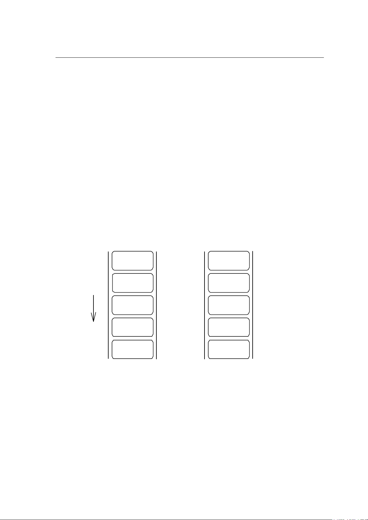
1-73
Setting subtraction of previous-defined printing contents (field data) 2
Code
Setting
Function
Example
Input data
< pii..
p Specifies character (all ASCII characters available) for filling zero.
ii Amount of subtraction (use of ASCII characters of A - Z prohibited)
Subtracts field data which was defined before this command by using
base 36 system of 0 - 9, A - Z.
Input data below represents that data "1000" is printed 5 sheets by
using this command while specifying 5 for the amount of subtraction.
[02] n Sets units to inch
[02] L Starts label format mode
D11 Sets pixel size
1900010000000501000 Sets data "1000" with smooth font 48pt
<05 Amount of subtraction: -5
Q0005 Specifies 5-sheet-printing
E Ends label format mode and prints
In case of subtraction “<05”
In case of subtraction “<5”
Direction of feed
0ZZG
0ZZL
0ZZQ
0ZZV
1000
5th sheet
4th sheet
3rd sheet
2nd sheet
1st sheet
ZZG
ZZL
ZZQ
ZZV
1000
5th sheet
4th sheet
3rd sheet
2nd sheet
1st sheet
Page 76

1-74
Setting number of prints for same label
0003
Code
Setting
Function
Example
Input data
^ nn
nn 2-digit numeric 01 - 99
Specifies number of prints for same label when addition and
subtraction and time printing are specified.
Executes addition, subtraction, etc. after printing number of sheets
specified with nn.
Specifies addition and subtraction per field, but if the number of prints
for same labels is specified for one label, this specification will be
effective to all fields.
Input data below represents that data "0001" is printed 5 sheets by
using this command while specifying 2 for the amount of addition and
2 sheets of prints for same printing contents.
[02] n Sets units to inch
[02] L Starts label format mode
D11 Sets pixel size
1900010000000500001 Sets data "0001" with smooth font 48pt
+02 Amount of addition: +2
^ 02 Sets 2 sheets for same printing contents
Q0005 Specifies 5-sheet-printing
E Ends label format mode and prints
0005
Direction of feed
0003
0001
0001
5th sheet
4th sheet
3rd sheet
2nd sheet
1st sheet
Page 77

1-75
Setting number of cuts (4-digit)
Code
Setting
Function
Caution
Example
Input data
: nnnn
nnnn 0001 - 9999 Initialization value: 0001
Cuts paper after printing same labels by specified number.
This command is invalid unless auto-cutter is mounted and cutter is
set to ON.
Input data below represents that same labels are printed 10 sheets
and cut every 2 sheets.
[02] n Sets units to inch
[02] L Starts label format mode
D11 Sets pixel size
Q0010 Sets 10 sheets for printing same
labels
1F3306000050050490123456789 Sets EAN13 bar code for data
"490123456789"
:0002 Sets 2 sheets for number of cuts
E Ends label format mode and
prints
Page 78

1-76
Character field definition
O
ABC
123
Code
Setting
rotate, font, hexp, vexp, point, row, column, d1, d2,.......
rotate Sets rotation direction for character data 1, 2, 3, 4
1: 0 º 2: 90 º 3: 180 º 4: 270 º
font Sets font , type of character (see table 1)
hexp Sets expansion rate in horizontal direction 1 - 9, A -
(A - O corresponding to 10 - 24)
vexp Sets expansion rate in vertical direction 1 - 9, A – O
(A - O corresponding to 10 - 24)
point Sets size of smooth font
A06 – A72 (corresponding to 6pt - 72pt)
Sets downloading font ID 100 - 999 (see table 2)
Setting of this item is valid only when font is set to 9.
row Row address 0000 - 9999 Unit: 0.01 inch
column Column address 0000 - 0410 Unit: 0.01 inch
d1, d2,.. Printing character data Character data ending with CR
By setting [02] Sn (n is a calling character string parameter
specifying A - P), character string data stored in the global
register is picked out and printed.
Function
Example
Input data
Direction of feed
Prints characters for content data entered with items such as rotation,
vertical and horizontal expansion rate, type of font and printing
position.
Input data below represents that data "123" is printed with system font
6, vertical and horizontal expansion rate 1 and row and column
address 0.5 inch, and data "ABC" is printed with smooth font 30pt and
vertical and horizontal expansion rate row address 1.0 inch and
column address 0.5 inch.
[02] n Sets units to inch
[02] L Starts label format mode
D22 Sets pixel size
16 11 000 0050 0050 123 Sets data "123" with system font 6
19 11 A30 0100 0050 ABC Sets data "ABC" with smooth font 30pt
E Ends label format mode and prints
Column address
(column)
Rotation 0°smooth font 30 pt
°
and vertical and horizontal
Row address
Rotation 0
expansion rate 1 system font 6
(row)
Page 79

1-77
Table 1-A ( 203 dpi print head )
Dot number Pixel size horizontal (H) x vertical (V) Units (mm)
Type of character
System font 0 5
1 7
2 10
3 14
4 18
5 18
6 32
7 15
8 15
Font H Space V 1 x 1 2 x 2 2 x 3 3 x 2 *1
1 7 0.8 x 0.9 1.5 x 1.8 1.5 x 2.6 2.3 x 1.8
2 13 1.1 x 1.6 2.3 x 3.3 2.3 x 4.9 3.4 x 3.3
2 18 1.5 x 2.3 3.0 x 4.5 3.0 x 6.8 4.5 x 4.5
2 27 2.0 x 3.4 4.0 x 6.8 4.0 x 10.1 6.0 x 6.8
3 36 2.6 x 4.5 5.3 x 9.0 5.3 x 13.5 7.9 x 9.0
3 52 2.6 x 6.5 5.3 x 13.0 5.3 x 19.5 7.9 x 13.0
4 64 4.6 x 8.0 9.0 x 16.0 9.0 x 24.0 13.5 x 16.0
5 32 2.5 x 4.0 5.0 x 8.0 5.0 x 12.0 7.5 x 8.0
5 28 2.5 x 3.5 5.0 x 7.0 5.0 x 10.5 7.5 x 7.0
Table 1-B ( 300 dpi print head )
Dot number Pixel size horizontal (H) x vertical (V) Units (mm)
Type of character
System font 0 6
Font H Space V 1 x 1 2 x 2 2 x 3 3 x 2 *1
1 10 0.6 x 0. 8 1.2 x 1.7 1.2 x 2.5 1.8 x 1.7
1 10
2 14
3 18
4 24
5 24
6 42
7 22
8 21
Note: *1 represents that character rotation direction is 90 and 270 deg.
3 18 1.1 x 1. 5 2.2 x 3.0 2.2 x 4.6 3.3 x 3.0
3 27 1.4 x 4.8 2.9 x 9.7 2.9 x 14.5 4.3 x 9.7
3 36 1.8 x 3. 0 3.6 x 6.1 3.6 x 9.1 5.3 x 6.1
4 48 2.4 x 4. 1 4.7 x 8.1 4.7 x 12.2 7.1 x 8.1
4 72 2.4 x 6. 1 4.7 x 12.2 4.7 x 18.3 7.1 x 12.2
6 88 4.1 x 7.5 8.1 x 14.9 8.1 x 22.4 12.2 x 14.9
7 46 2.5 x 2.7 4.9 x 5.4 4.9 x 8.1 7.4 x 5.4
8 33 2.5 x 2.7 4.9 x 5.4 4.9 x 8.1 7.4 x 5.4
Horizontal (H)
Vertical (V)
AB
Page 80

1-78
Table 2
Type of character Font Point or downloading ID Point number note
Smooth font 9 A04 - 4pt
Triumvirate A05 - 5pt
A06 001 6pt
A08 002 8pt
A10 003 10pt
A12 004 12pt
A14 005 14pt
A18 006 18pt
A24 007 24pt
A30 008 30pt
A36 009 36pt
Smooth font 9 C04 - 4pt
Triumvirate Bold C05 - 5pt
C06 121 6pt
C08 122 8pt
C10 123 10pt
C12 124 12pt
C14 125 14pt
C18 126 18pt
C24 127 24pt
C30 128 30pt
C36 129 36pt
C48 130 48pt
C72 131 72pt
A48 010 48pt
A72 011 72pt
Available only
with 300 DPI
models
Available only
with 300 DPI
models
Downloading font 9 100 - 999
TrueType
Downloading font
9 S50 – S5z, …. S90 – S9z
s50 – s5z, …. s90 – s9z
U50 – U5z, …. U90 – U9z
u50 – u5z, …. u90 – u9z
In Binary code
In Hexadecimal
code
For double-byte
characters
In Binary code
For double -byte
characters
In Hexadecimal
code
Page 81

1-79
Type Font Character field definition
O
Code
Setting
Function
rotate, font, hexp, vexp, id, row, column, height, width, d1, d2,.......
rotate Sets rotation direction for character data 1, 2, 3, 4
1: 0 º 2: 90 º 3: 180 º 4: 270 º
font 9 fixed
hexp Sets expansion rate in horizontal direction 1 - 9, A -
(A - O corresponding to 10 - 24)
vexp Sets expansion rate in vertical direction 1 - 9, A – O
(A - O corresponding to 10 - 24)
id Download font ID Refer to table 2.
row Row address 0000 - 9999 Unit: 0.01 inch
column Column address 0000 - 0410 Unit: 0.01 inch
height Sets character height by a code of “P”+3 characters
Number of dots set by unit of a dot.
Width Sets character width by a code of “P”+3 characters
Number of dots set by unit of a dot.
d1, d2,.. character data followed by “CR” code to end
Downloaded TrueType font is printed in the print mode specified by
this command.
Example
Input data
Print the characters, “TrueType”, in TrueType font (ID=54) with 24 pt
height and width.
[02] n Sets units to inch
[02] L Starts label format mode
D11 Sets pixel size
ySUK Sets symbol set for UK.
19 11 S54 0100 0100 P024 P024 TrueType
E Ends label format mode and
prints
Page 82

1-80
Bar code field definition
digit numeric
4
567894
Row address
Bar code type
Code
Setting
Function
Example
Rotate, font, thick, narrow, height, row, column, d1, d2,.......
rotate Sets rotation direction for bar code 1, 2, 3, 4
1: 0 º 2: 90 º 3: 180 º 4: 270 º
Font Sets type of bar code (see table 3)
thick Sets thick bar width in 1-dot units (0.005 inch)
1 - 9, A - O (A - O corresponding to 10 - 24)
narrow Sets narrow bar width in 1-dot units (0.005 inch)
1 - 9, A - O (A - O corresponding to 10 - 24)
height Sets height of bar code data by using 3-
001 - 999 Unit: 0.01 inch
row Row address 0000 - 9999 Unit: 0.01 inch
column Column address 0000 - 0410 Unit: 0.01 inch
d1, d2,.. Bar code data See table 3
Encodes contents data specified with items such as rotation, size of
bar code data and printing position into bar code and prints.
Input data below is prepared with the following setting and printed.
Input data
Direction of feed
font EAN-13
bar ratio (thick : narrow) 3:3
height 0.6 inch
row, column 0.5 inch, 0.5 inch
d1, d2,.. 490123456789
[02] n Sets units to inch
[02] L Starts label format mode
D11 Sets pixel size
1F3306000500050490123456789 Sets EAN13 bar code for data
"490123456789"
E Ends label format mode and
prints
Column address
(column)
Bar code height
(font)
(height)
901234
(row)
Page 83

1-81
Table 3
Font Bar code name Bar ratio (thick:narrow) No. of valid data
A Code 3 of 9 3:1 Variable length
B UPC-A 1:1, 2:2, 3:3, 4:4, 6:6, 8:8 12
C UPC-E 1:1, 2:2, 3:3, 4:4, 6:6, 8:8 8
D Interleaved 2 of 5 5:2 Even digit
variable length
E Code 128 Variable length
F EAN-13 (JAN-13) 1:1, 2:2, 3:3, 4:4, 6:6, 8:8 13
G EAN-8 (JAN-8) 1:1, 2:2, 3:3, 4:4, 6:6, 8:8 8
H
I CODERBAR (NW -7) 3:1 Variable length
J
K Plessey Variable length
L CASE CODE 5:2 14
M
N
O Code 93 1:1, 2:2, 3:3, 4:4, 6:6, 8:8 Variable length
p ZIP Variable length
Q UCC/EAN128 1:1, 2:2, 3:3, 4:4, 6:6, 8:8 19*
R UCC/EAN128 (for K-MART) 1:1, 2:2, 3:3, 4:4, 6:6, 8:8 18*
S UCC/EAN128 Random Weight 1:1, 2:2, 3:3, 4:4, 6:6, 8:8 34 or more*
T Telepen Variable length*
HIBC
(Modulus 43 -used Code 3 of 9)
Int 2 of 5
(Modulus 10-used Interleaved 2 of 5)
UPC 2DIG ADD
(UPC 2-digit supplementary code)
UPC 5DIG ADD
(UPC 5-digit supplementary code)
3:1 Variable length
5:2
3
6
Odd digit variable
length
U / u UPS MaxiCode 84 or less*
V FIM 1*
Z / z PDF417 Variable length
W1C/W1c DataMatrix Variable length
W1D/W1d QR CODE Variable length
W1F/W1f Aztec Variable length
Head of character
string= q
Head of character
string=M
(The number of valid data marked with asterisk is only used for input data length.)
QR CODE
Matrix 2 of 5
Variable length ESC
5:2 Variable length
Page 84

1-82
Ruled line definition
hhhh<
vvvv
Code
Setting
Units
Function
Example
1X11, 000, row, column, Lhhhvvv or lhhhhvvvv
1X11 1X11 fixed
000 000 fixed
row row address 0000 - 9999
column column address 0000 - 0398
L Specifies line (3-digit)
hhh Specifies horizontal width
v v v Specifies vertical width
l Specifies line (4-digit)
hhhh Specifies horizontal width
v v v v Specifies vertical width
0.01 inch
Prints ruled line with specified width. hhhh>vvvv designates
horizontal line. hhhh<vvvv designates vertical line.
Input data below represents that ruled line with horizontal width of hhh
10 and vertical width of vvv 150 and ruled line with horizontal width of
hhh 200 and vertical width of vvv 10 are printed.
Input data
[02] n Sets units to inch
[02] L Starts label format mode
1X1100000500050L010150 Sets ruled line with 0.1 x 1.5 inch
1X1100000500100L200010 Sets ruled line with 2.0 x 0.1 inch
E Ends label format mode and prints
hhhh>vvvv
Direction of feed
Page 85

1-83
Box definition
Code
Setting
1X11, 000, row, column, Bhhhvvvbbbsss or bhhhhvvvvbbbbssss
1X11 1X11 fixed
000 000 fixed
row row address 0000 - 9999
column column address 0000 - 0410
B Specifies box (3-digit)
hhh Specifies horizontal width of box
v v v Specifies vertical width of box
bbb Specifies top and bottom line width
sss Specifies left and right line width
b Specifies box (4-digit)
hhhh Specifies horizontal width of box
v v v v Specifies vertical width of box
bbbb Specifies top and bottom line width
ssss Specifies left and right line width
Units
Function
Example
Input data
0.01 inch (0.1 mm)
Prints box with specified dimension.
Input data below represents that box with horizontal width of hhh 200,
vertical width of vvv 100, upper and lower ruled line width of bbb 10
and both side line width of sss 3 is printed.
[02] n Sets units to inch
[02] L Starts label format mode
1X1100000500050B200100010003 Sets box with 2.0 (horizontal) x
1.0 (vertical) inch
E Ends label format mode and
prints
hhh=200
vvv=100
sss=003
bbb=010
Page 86

1-84
Graphics printing definition
O
Code
Setting
Function
Caution
Example
rotate, Y, hexp, vexp, 000, row, column, graphic
rotate Sets graphic data rotation direction to 1 (fixed)
Y Y fixed
hexp Sets expansion rate in horizontal direction 1 - 9, A – O
(A - O corresponding to 10 - 24)
vexp Sets expansion rate in vertical direction 1 - 9, A -
(A - O corresponding to 10 - 24)
000 000 fixed
row Row address 0000 - 9999
column Column address 0000 - 0398
graphic Specifies graphic file name to be printed
Picks out file name from the memory module and prints.
Graphic file to be printed with this command must be stored in the
memory module.
Input data below represents that file name "IMAGE" in the memory
module is printed.
Input data
[02] n Sets units to inch
[02] L Starts label format mode
1Y1100000500050IMAGE Sets graphic file name "IMAGE"
E Ends label format mode and prints
Page 87

1-85
Polygon definition
Code
Setting
Units
Function
1X11, ppp, row, column, P ppp bbbb row, column, row, column
1X11 1X11 fixed
ppp Dot pattern 000 – 011
row 1st point row address 0000 – 9999
column 1st point column address 0000 – 0398
P Specifies polygon
ppp 001 fixed
bbbb 0001 fixed
row 2nd point row address 0000 – 9999
column 2nd point column address 0000 – 0398
row 3rd point row address 0000 – 9999
column 3rd point column address 0000 – 0398
After this, repeats row and column
0.01 inch (0.1 mm)
Draws polygon with specified point and dots inside with specified
pattern.
Dot pattern
12 dot patterns from 0 – 11 are shown below.
000
(0%)
001
(100%)
002
(6.25%)
003
(12.5%)
004
(25%)
005
(37.5%)
006
(50%)
007
(62.5%)
008
(69.14%)
009
(62.5%)
010
(62.5%)
011
(43.75%)
Page 88

1-86
Example
Input data
Input data below represents that triangle with three points, row 0.20
inch/column 0.10 inch, row 0.60 inch/column 0.30 inch, and row 0.20
inch/column 0.50 inch, is drawn and inside is dotted with pattern 6
(50% black).
[02] n Sets units to inch
[02] L Starts label format mode
D11 Sets pixel size
1X11 006 0020 0010 P 001 0001 0060 0030 0020 0050
Sets polygon
E Ends label format mode and
prints
Example
Input data
Input data below represents that rectangle with four points, row 0.20
inch/column 0.20 inch, row 0.40 inch/column 0.20 inch, row 0.40
inch/column 1.00 inch, and row 0.20 inch/column 1.00 inch, is drawn
and inside is dotted with pattern 8 (little circle).
[02] n Sets units to inch
[02] L Starts label format mode
D11 Sets pixel size
1X11 008 0020 0020 P 001 0001 0040 0020 0040 0100 0020 0100
Sets polygon
E Ends label format mode and
prints
Page 89

1-87
Circle definition
Code
Setting
Units
Function
Example
1X11, ppp, row, column, C ppp bbbb, radius
1X11 1X11 fixed
ppp Dot pattern 000 – 011
row Circle center row address 0000 – 9999
column Circle center column address 0000 – 0398
C Specifies circle
ppp 001 fixed
bbbb 0001 fixed
radius Radius 0000 – 0398
0.01 inch
Draws circle with specified center and radius and dots inside with
specified pattern.
Input data below represents that circle with center of row 0.50
inch/column 0.50 inch and radius of 0.30 inch is drawn and inside is
dotted with pattern 10 (left diagonal lines).
Input data
[02] n Sets units to inch
[02] L Starts label format mode
D11 Sets pixel size
1X11 010 0050 0050 C 001 0001 0030 Sets circle
E Ends label format mode and
prints
Page 90

1-88
Reading out from global register
O
Code
Setting
rotate, font, hexp, vexp, point, row, column, [02], S, a
rotate Sets rotation direction for character data 1, 2, 3, 4
1: 0 º 2: 90 º 3: 180 º 4: 270 º
Font Sets type of character (see table 1)
hexp Sets expansion rate in horizontal direction 1 - 9, A -
(A - O corresponding to 10 - 24)
vexp Sets expansion rate in vertical direction 1 - 9, A – O
(A - O corresponding to 10 - 24)
point Sets size of smooth font
CG Triumvirate:A06 – A72 (corresponding to 10 types of 6 to
72pt)
Setting of this item is valid only when font is set to 9.
row Row address 0000 - 9999 Unit: 0.01 inch
column Column address 0000 - 0410 Unit: 0.01 inch
[02] [02]hex fixed
S Specifies reading out of global register
a Specifies global register No. Alphabet (from A to P)
Function
Example
Reads out data stored in global register with G command.
See sample No. 3 in Appendix 5.
Page 91

1-89
Date and time printing definition
Code
Setting
rotate, font, hexp, vexp, point, row, column, [02], T, tdata...
rotate Sets rotation direction for character data 1, 2, 3, 4
1: 0 º 2: 90 º 3: 180 º 4: 270 º
Font Sets type of character (see table 1)
hexp Sets expansion rate in horizontal direction 1 - 9, A – O
(A - O corresponding to 10 - 24)
vexp Sets expansion rate in vertical direction 1 - 9, A – O
(A - O corresponding to 10 - 24)
point Sets size of smooth font
A06 – A72 (corresponding to 6 to 72pt)
Setting of this item is valid only when font is set to 9.
row Row address 0000 - 9999 Unit: 0.01 inch
column Column address 0000 - 0410 Unit: 0.01 inch
[02] [02]hex fixed
T Specifies writing of time data
tdata... Specifies date and time printing format by using the following
alphabet and spaces
Function
Example
A 1-digit day of week 0 -6 (Sunday to Saturday)
BCD Name of day of the week Monday (MON)
EF 2-digit month number 1 - 12 (January to
December)
GHI...NO Name of the month January (JANUARY)
PQ 2-digit date 15 (day of 15)
RSTU 4-digit year number 1995 (year of 1995)
VW 2-digit time 24-hour display
XY 2-digit time 12-hour display
Za 2-digit minute 50 (minute of 50)
bc Morning, Afternoon AM (Morning), PM
(Afternoon)
Reads out and prints date and time in the calendar of the printer
according to the specified format with this command.
Input data below represents that date and time with specified format of
name of day of the week (BCD), name of the month (GHI), date (PQ)
and year number (RSTU) are printed.
Page 92

1-90
Input data
[02] n Sets units to inch
[02] L Starts label format mode
D11 Sets pixel size
190000500500050[02]TBCD GHI PQ, RSTU
Sets day of the week, month, date
and year number
E Ends label format mode and prints
Page 93

1-91
Chapter 2
Fonts and Bar
Codes
2.1 Description of Fonts 2-2
2.2 Description of Bar Codes 2-8
Page 94

1-92
Fonts and bar codes for this printer are listed below. Each name is expressed in
numeric for fonts and in alphabetic characters for bar codes. Visible or non-visible code
is identified with upper-case or lower-case alphabetic characters for the bar code name.
Upper-case characters allow printer to print visible code bar code, while lower-case
characters allow printer to print non-visible code bar code.
2.1 Description of Fonts
The following print sample is printed with pixel size of 1 dot x 1 dot, and the
dot pattern in horizontal and vertical direction is printed with 1 time.
Font 0: Upper- and lower-case alphanumeric characters.
Character size:
203 dpi: 7 dots (height) x 5 dots (width) x 1 dot (space)
300 dpi: 10 dots (height) x 6 dots (width) x 1 dots (space)
Font 1: Upper- and lower-case alphanumeric characters.
Character size:
203 dpi: 13 dots (height) x 7 dots (width) x 2 dots (space)
300 dpi: 18 dots (height) x 10 dots (width) x 3 dots (space)
Page 95

1-93
Font 2: Upper- and lower-case alphanumeric characters.
Character size:
203 dpi: 18 dots (height) x 10 dots (width) x 2 dots (space)
300 dpi: 27 dots (height) x 14 dots (width) x 4 dots (space)
Font 3: Upper- and lower-case alphanumeric characters.
Character size:
203 dpi: 27 dots (height) x 14 dots (width) x 2 dots (space)
300 dpi: 36 dots (height) x 18 dots (width) x 3 dots (space)
Page 96

1-94
Font 4: Upper- and lower-case alphanumeric characters.
Character size:
203 dpi: 36 dots (height) x 18 dots (width) x 3 dots (space)
300 dpi: 48 dots (height) x 24 dots (width) x 4 dots (space)
Font 5: Upper- and lower-case alphanumeric characters.
Character size:
203 dpi: 52 dots (height) x 18 dots (width) x 3 dots (space)
300 dpi: 72 dots (height) x 24 dots (width) x 4 dots (space)
Page 97

1-95
Font 6: Upper- and lower-case alphanumeric characters.
Character size:
203 dpi: 64 dots (height) x 32 dots (width) x 4 dots (space)
300 dpi: 88 dots (height) x 42 dots (width) x 6 dots (space)
Font 7: Upper-case alphabetic characters and numeric OCR-A font.
Character size:
203 dpi: 32 dots (height) x 15 dots (width) x 5 dots (space)
300 dpi: 46 dots (height) x 22 dots (width) x 7 dots (space)
Page 98

1-96
Font 8: Upper- and lower-case alphabetic characters and numeric CR-B font.
Character size:
203 dpi: 28 dots (height) x 15 dots (width) x 5 dots (space)
300 dpi: 33 dots (height) x 21dots (width) x 8 dots (space)
Page 99

1-97
Font 9: Upper- and lower-case alphabetic characters, numeric and
extension font (CG Triumvirate smooth font). Character size is any
of 6, 8, 10, 12, 14, 18, 24, 30, 36, 48 or 72 points.
Page 100

1-98
2.2 Description of Bar Codes
The following print sample is printed with a pixel size of 1 dot x 1 dot. The dot
pattern in horizontal and vertical direction is printed with 1 time.
Bar code A: Code 3 of 9
This bar code consists of upper-case alphanumeric characters.
Number of digits is variable in length. Start/stop codes "*" are given
automatically by printer. Valid ASCII codes are as follows: 32, 36-37,
43, 45-47, 48 -57, 65-90. Standard ratio (ratio of thick bar to thin bar) of
Code 3 of 9 is 3: 1.
Bar code B: UPC-A
This bar code consists of only numeric characters and is 12-digit fixed
length. The 11-digit numerics are input from the computer or
applications software and the 12th digit is a checksum that is
calculated automatically by the printer.
When the computer sends the 12th digit numeric, the printer
compares the characters with the calculated checksum. If they do not
agree, the printer prints all bar codes 0 (zero).
If supplementary code is to be added, refer to item of bar code M and
N. Element size is 1 : 1, 2 : 2, 3 : 3, 4 : 4, 6 : 6, and 8 : 8.
 Loading...