

Page 1
Installation Guide 7010 Auto Cutter
– 1 –
Page 2

©
August 2010 DASCOM Europe GmbH
Page 3
Installation Guide
CAUTION: For use by service representatives!
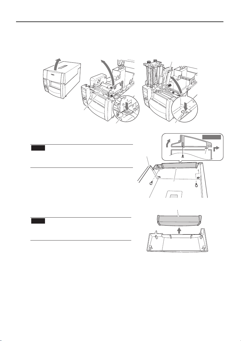
(1) Check to make sure that the printer’s power switch is turned off then disconnect the
power cord.
(2) Open the top cover and lift the thermal printhead and sensor arm.
Sensor arm
Thermal printhead
Head open lever Sensor arm open lever
(3) Remove the front top cover from the top
cover. (2 screws)
Note There is a hook on the front top cover.
Be careful not to bend the hook while
removing the front top cover from the
top cover.
To p c ove r
Side view
Hook
(4) Remove the cutter attachment cover from
the front top cover that you have removed.
Note The cutter attachment cutter that
you have removed is used to remove
the auto-cutter unit, so store it
carefully.
– 3 –
Front top cover
Cutter attachment cover
Page 4

(5) Remove the operation panel on the front of the printer. (2 screws)
When doing this, remove the flexible cable that is connected to the operation panel.
Flexible cable
(6) Remove the front right cover on the front of the printer. (2 screws)
(7) Remove the pulley cover (black) that is on the right front part of the printer. (1 screw)
Using nippers, cut out the notch on the pulley cover that you have removed.
Notch
– 4 –
Page 5

8) Remove the front center cover. (2 screws)
9) Remove the front cover from the front center cover that you have removed. (2 screws)
Note The front cover that you have
removed is used when the
auto-cutter unit has been
removed, so store it carefully.
Front cover
10) Attach the pulley cover (black) that you
removed at step 7 in its original position.
11) Connect the connector of the auto-cutter unit to the relay printed circuit board as
shown in the figure.
Pass through
this hole
Relay printed
circuit board
Note If you pass the connector through in the wrong insertion direction, it cannot be
connected. Insert it after checking the direction of the connector (1 pin on the
bottom).
– 5 –
Page 6

(12) Insert the claw on the right side of the auto-cutter unit into the notch on the printer,
then fix it in place with the attached screw (1).
Be sure to pass the cable
between the metal plate and
the pulley cover.
Metal
plate
Pulley cover
Notch
Claw
(13) Attach the front center cover from step 9 in its original position. (2 screws)
(14) Attach the front right cover removed at step 6 in its original position. (2 screws)
(15) Attach the operation panel removed at step 5 in its original position. (3 screws)
Note Be sure to connect the flexible cable that you disconnected as it was formerly
connected. The blue side .sdrawpu si pit eht fo
(16) Attach the front top cover from step 4 in its original position. (2 screws)
(17) Close the top cover.
(18) Connect the power cord and turn on the power switch
on the printer.
Note Removing the auto-cutter unit
To remove the auto-cutter unit from the printer,
follow the installation steps in reverse order. If the
screws that fasten the auto-cutter unit are
removed, the unit may fall from the printer, so
hold the auto-cutter unit with your hand while
loosening the fastening screws.
– 6 –
Page 7

– 7 –
Page 8

DASCOM REPRESENTATIVES
GERMANY
DASCOM Europe GmbH
Heuweg 3
D-89079 Ulm
Deutschland
Tel.: +49 (0) 731 2075 0
Fax: +49 (0) 731 2075 100
www.dascom.com
SINGAPORE
DASCOM AP Pte Ltd
63 Hillview Avenue
#08-22, Lam Soon Industrial Building
Singapore 669569
Phone: +65 6760 8833
Fax: +65 6760 1066
www.dascom.com
AMERICAS
DASCOM Americas Corporation
421 W. Main Street
Waynesboro, VA 22980
USA
Phone: +1 (877) 434 13 77
www.dascom.com
© August 2010 DASCOM Europe GmbH v1.0
UNITED KINGDOM
DASCOM GB Ltd
ViewPoint, Basing View,
Basingstoke, Hampshire
RG21 4RG, England
Phone: +44 (0) 1256 481481
Fax: +44 (0) 1256 481400
www.dascom.com
FRANCE
DASCOM Europe GmbH
117 Avenue Victor Hugo
92100 Boulogne-Billancourt
France
Phone: +33 (1)73 02 51 98
www.dascom.com
RUSSIA and CIS
DASCOM Europe GmbH
Representation Moscow
Leninsky Prospekt 95a, Office 322
119313 Moscow, Russian Federation
Phone: +7 (495) 984 70 65
Fax: +7 (495) 984 56 42
www.dascom.com
CEE
DASCOM Europe GmbH
Europaring F15 301
2345 Brunn a. G.
Austria
Phone: +43 (1) 236 01 70 10
www.dascom.com
 Loading...