

Page 1
Installation Guide
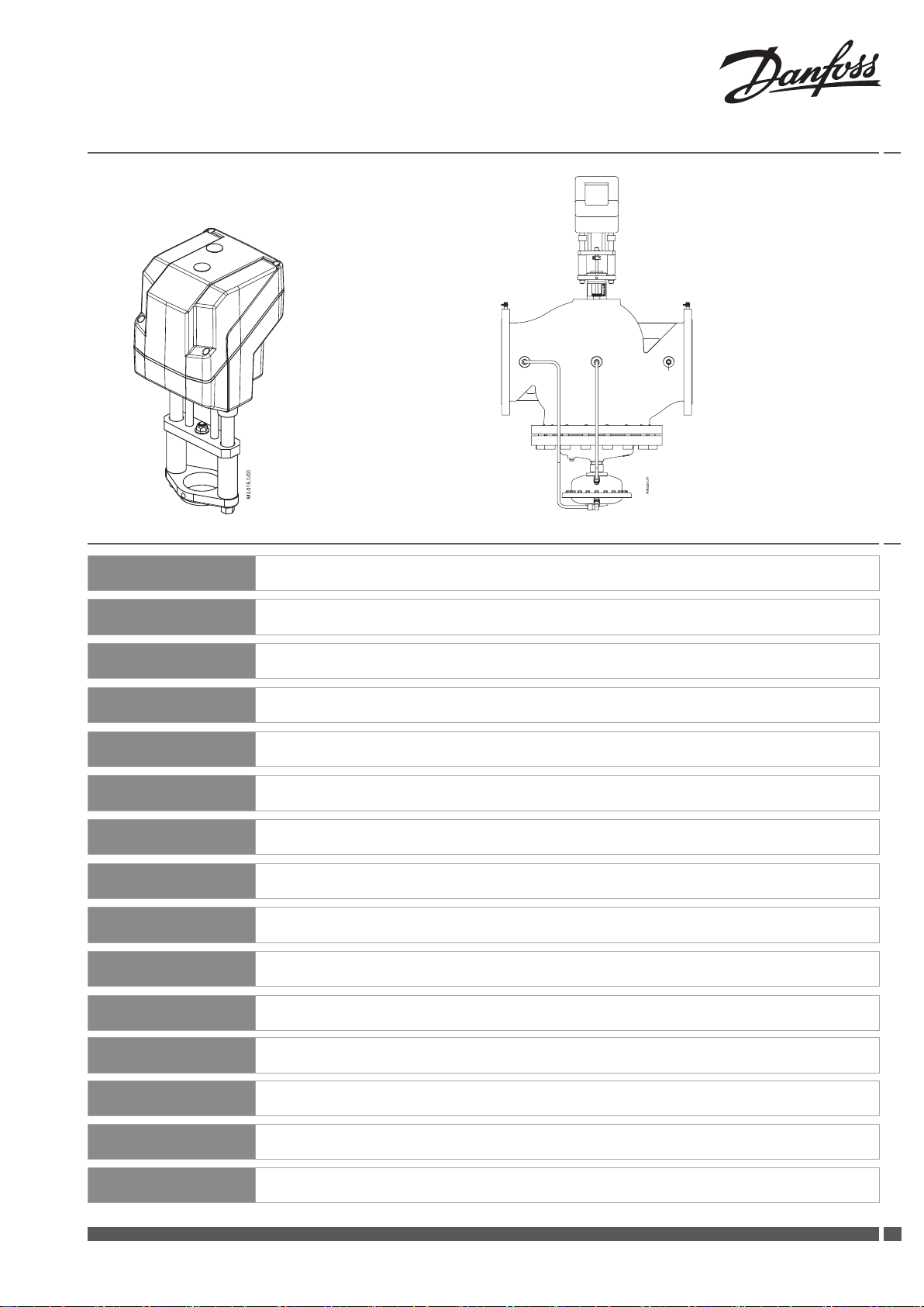
AME 85QM
AME 85QM +AB-QM (DN 200, 250)
ENGLISH
ČESKY
DEUTSCH
FRANÇAIS
ITALIANO
L ATV IS KI
LIETUVIŲ K.
MAG YAR
POLSKI
ROMÂNĂ
SUOMI
AME 85QM www.danfoss.com Page 4
AME 85QM www.cz.danfoss.com Strana 6
AME 85QM www.waerme.danfoss.de Seite 8
AME 85QM www.danfoss.fr Page 10
AME 85QM www.danfoss.it Pagina 12
AME 85QM www.danfoss.lv Page 14
AME 85QM www.sildymas.danfoss.lt 16 psl
AME 85QM www.danfoss.com 18. oldal
AME 85QM; www.heating.danfoss.pl Strona 20
AME 85QM www.incalzire.danfoss.com Pagina 22
AME 85QM www.lpm.danfoss. Sivu 24
SLOVENŠČINA
БЪ ЛГА РСК И
РУССКИЙ
中文
Danfoss Heating VI.CV.E1.3U SMT/SI
AME 85QM www.danfoss.com Stran 26
AME 85QM www.danfoss.com Страница 28
AME 85QM www.danfoss.ru Стр. 30
AME 85QM www.danfoss.com 第 32 页
1
Page 2
2
Installation Guide AME 85QM
SMT/SI VI.CV.E1.3U Danfoss Heating
❶
❷
Remove tap
①
②
Push
③
Tur n
❸
❹
Page 3
Installation Guide AME 85QM
❺
①
④
②
⑤
③
⑥
⑦
⑧
⑨
⑩
Danfoss Heating VI.CV.E1.3U SMT/SI
33
Page 4
4
Installation Guide AME 85QM
SMT/SI VI.CV.E1.3U Danfoss Heating
ENGLISH
Safety Note
Prior to assembly and commissioning
to avoid injury of persons and damages
of the devices, it is absolutely necessary
to carefully read and observe these
instructions.
Necessary assembly, start-up, and
maintenance work must be performed
only by qualied, trained and authorized
personnel.
Prior to assembly and maintenance work
on the controller, the system must be:
- depressurized,
- cooled down,
- emptied and
- cleaned.
Please comply with the instructions of the
system manufacturer or system operator.
Do not remove the cover before the power
supply is fully switched o.
Disposal instruction
This product should be
dismantled and its
components sorted, if
possible, in various groups
before recycling or disposal.
Always follow the local disposal
regulations.
Mounting
Fix the AME 85QM on the valve.
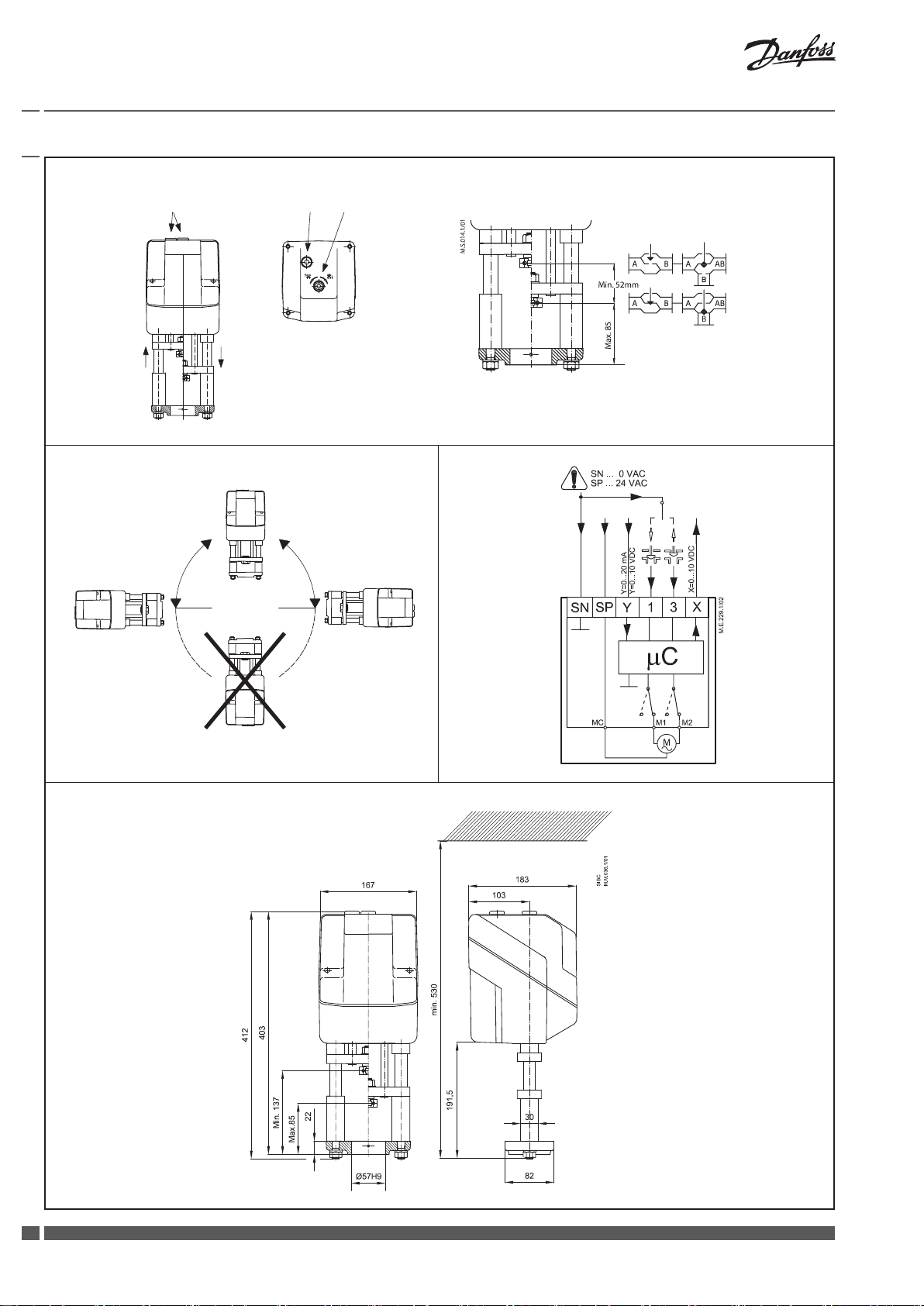
Admissible Installation Positions ❷.
Wiring ❸
Do not touch anything on the PCB!
Switch o the power line before wire the
actuator! Lethal voltage!
Wire the actuator according to the wiring
diagram.
Control signal
Control signal from the controller must be
connected to terminals Y (input signal) and
SN (common) on the AME printed board.
Output signal
Output signal from the terminal X can be
used for indication of the current position.
Range depends on the DIP switch settings.
Supply voltage
Supply voltage (24V~ -15 to +10 %, 50 Hz)
must be connected to the terminals SN
and SP.
Dimensions ❹
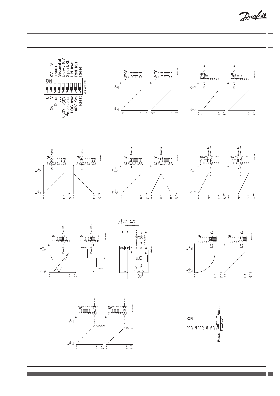
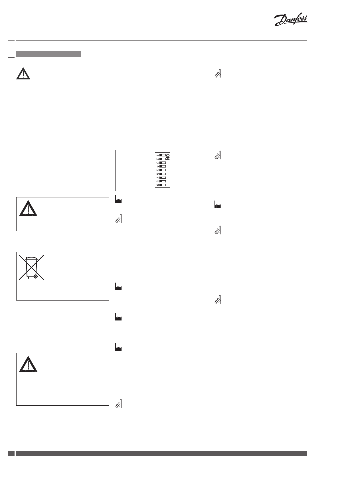
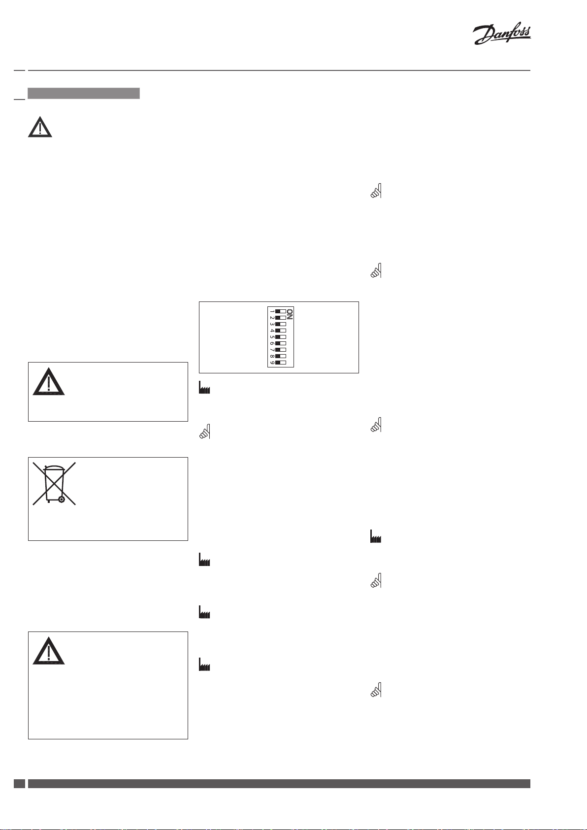
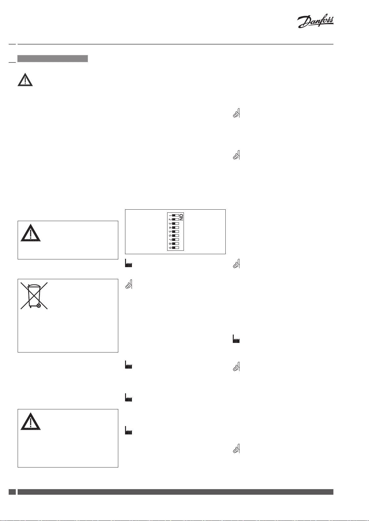
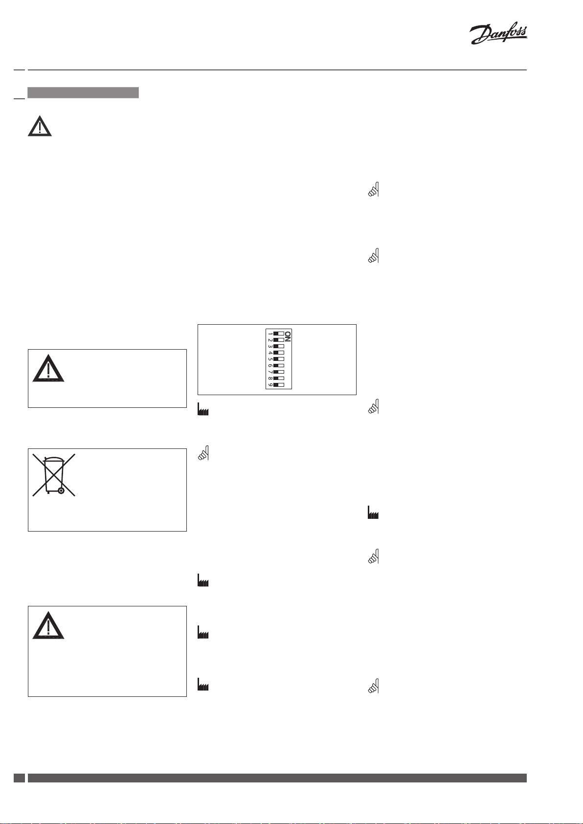
DIP switch settings ❺
Factory settings:
ALL switches are on OFF position! ❺①
Note:
All combinations of DIP switches are
allowed. All functions that are selected are
added consecutively. There is only one logic
override of functionalities i.e. the switch No.6
Proportional /3 point, which sets actuator to
ignore control signal and works as a “simple”
3-point actuator
SW1: U/I ❺②
Factory setting:
Voltage control signal (0-10 V).
SW2: 2-10 V/0-10 V ❺③
Factory setting is:
2-10 V.
SW3: Direct/Inverse ❺④
Factory setting is:
DIRECT
SW4: ---/Sequential ❺⑤
Two actuators can be set to work parallel
with one control signal. If the SEQUENTIAL
is set than an actuator responds to split
control signal (see 0(2)-5(6) V/5(6)-10 V).
Note:
This combination works in combination with
switch No.5: 0(2)-5(6)V/5(6)-10 V
U I
2 V_--- V 0 V_- -- V
Direct Inverse
--- Sequential
0(2)_5(6) V 5(6)_10 V
Proportional 3 point/RL
LOG. ow LIN . ow
100 % k
VS
Reset Reset
RED. k
VS
SW5: 0(2)-5(6) V/5(6)-10 V ❺⑥
Note:
This function is available if switch No.4: ---/
Sequential is set.
SW6: Proportional/3 point ❺⑦
Actuator can operate as “simple” 3-point
actuator, if the 3-point function is selected.
Power supply should be connected on
SN and SP ports. On port 1 or 3 24 VAC
signal is connected for rising or lowering
of actuator. Return signal X indicates the
correct position.
Note:
If 3 point function is selected actuator does
not respond to any control signal on port Y.
It only rises and lowers spindle if power is
supplied on port 1 or 3.
SW7: LOG. ow/LIN. ow ❺⑧
Factory setting is:
LOG. Flow (characteristic of valve is
unchanged)
Note:
Large AB-QM valve has linear characteristic.
With setting switch to LIN ow the
characteristic remains linear. With setting
switch to LOG ow the characteristic of
actuator is modied the way that actuator
and valve work together as valve with LOG
characteristic.
SW8: 100 % KVS/RED. KVS ❺⑨
Note:
This function works proper only with
logarithmic (equal percentage) valves.
SW9: Reset ❺⑩
After the actuator has been connected
to power supply, the actuator will start
the self-adjustment procedure. The
indicator LED ashes until self adjustment
is nished. The duration depends on the
spindle travel and will normally last a few
minutes. The stroke length of the valve is
stored in the memory after self adjustment
has been completed. To restart self
adjustment, change the position of RESET
switch (switch No.9). If the supply voltage
is switched o or falls below 80 % in more
than 0.1 s, the current valve position will be
stored in the memory and all data remain
saved in the memory also after a power
supply cut-out.
Page 5

Installation Guide AME 85QM
Manual override ❶
The manual override is applied by rotating
the 8 mm Allan key (not supplied) to the
required position. Observe the direction of
rotation symbol.
Function test
The indicator light shows whether the
positioner is in operation or not. Moreover,
the indicator shows the control status and
faults.
Constant light
- normal operation
No light
- no operation or no power supply
Intermittent light (1 Hz)
- self adjusting-mode
Intermittent light (3 Hz):
- power supply too low
- insucient valve stroke (<20 s)
- end-position cannot be reached.
Danfoss Heating VI.CV.E1.3U DH-SMT/SI
55
Page 6
6
Installation Guide AME 85QM
SMT/SI VI.CV.E1.3U Danfoss Heating
ČESKY
Bezpečnostní pokyny
Z důvodu maximálního snížení možnosti
poranění osob nebo vzniku škod na
majetku je bezpodmínečně nutné se před
vlastní montáží a uvedením regulátoru
do provozu pečlivě seznámit se všemi zde
uvedenými bezpečnostními informacemi.
Nezbytné montážní práce, kroky při uvádění
do provozu a opravy mohou provádět
pouze kvalikovaní, proškolení pracovníci,
kteří pro tuto činnost byly určeni.
Před montáží nebo před případnou opravou
nebo servisem regulátoru je nutné, aby regulovaný systém splňoval následující podmínky:
- nebyl pod tlakem,
- byl dostatečně ochlazen,
- vyprázdněn a
- vyčištěn.
Postupujte podle návodu výrobce systému
nebo jeho provozovatele.
Nesundávejte kryt, dokud není napájení
zcela vypnuto.
Pokyny pro likvidaci
Tento výrobek by měl být
před recyklací nebo likvidací
rozebrán na součástky a ty
umístěny do různých skupin
odpadu.
Vždy dbejte aktuálních pokynů místní
legislativy.
Montáž
Upevněte AME 85QM na ventil.
Přípustná instalační poloha ❷.
Zapojení ❸
Řídicí signál
Řídicí signál z řídicí jednotky musí být připojen
ke svorkám Y (vstupní signál) a SN (společný
vodič) na desce tištěných spojů AME.
Výstupní signál
Výstupní signál ze svorky X lze použít pro
indikaci aktuální polohy. Rozsah závisí na
nastavení přepínačů DIP.
Napájecí napětí
Napájecí napětí (24 V~ -15 až +10 %, 50 Hz)
musí být připojeno ke svorkám SN a SP.
Rozměry ❹
Nastavení DIP spínače ❺
Tovární nastavení:
VŠECHNY spínače jsou nastaveny do
VYPNUTÉ polohy! ❺①
Poznámka:
Všechny kombinace přepínačů DIP jsou
povoleny. Všechny funkce, které jsou vybrány,
jsou přidány po sobě. Existuje pouze jedno
logické potlačení funkcí, tj. spínač č.6
Volba modulačního nebo třípolohového
režimu, který nastavuje servopohon tak,
aby ignoroval řídicí signál a plnil funkci
„jednoduchého“ 3bodového servopohonu.
Spínač č. 1: U/I ❺②
Tovární nastavení:
Napěťový reg ulační signál (0-10 V).
Spínač č. 2: 2-10 V/0-10 V ❺③
Tovární nastavení:
2-10 V.
Spínač č. 3: Přímý/Inverzní ❺④
U I
2 V_--- V 0 V_- -- V
Přímý Inverzní
--- Sekvenční
0(2)_5(6) V 5(6)_10 V
Proporcionální
Průtok LOG Prů tok LIN
100 % k
VS
Resetování Resetování
3bodový/RL
RED. k
Spínač č. 4: ---/Sekvenční ❺⑤
Dva servopohony lze nastavit tak, aby
pracovaly paralelně s jedním řídicím
signálem. Pokud je nastaven do polohy
ON, pracuje servopohon v sekvenčním
rozsahu:0(2)...5(6) V nebo 0(4)...10(12)mA
nebo 6(6)...10V nebo 10 (12)....20mA.
Poznámka:
Tato kombinace pracuje spolu se spínačem
č.5: 0(2)-5(6) V/5(6)-10 V
Spínač č. 5:
0(2)-5(6) V/5(6)-10 V ❺⑥
Poznámka:
Tato funkce je použitelná pouze s
nastaveným spínačem č. 4: ---/Sekvenční.
Spínač č. 6: Modulační nebo
třípolohový režim ❺⑦
Servopohon může pracovat jako
VS
„jednoduchý“ 3bodový servopohon, pokud
je navolená 3bodová funkce. Napájení by
mělo být připojeno k portům SN a SP. Na
portu 1 nebo 3 je připojen signál 24 V AC
pro zvedání nebo spouštění servopohonu.
Zpětný signál X signalizuje správnou polohu.
Poznámka:
Pokud navolíte 3bodovu funkci, servopohon
nereaguje na žádný řídicí signál na portu Y.
Pouze zvedne a spustí vřeteno, pokud je
napájení přivedeno na port 1 nebo 3.
Spínač č. 7: Průtok LOG/Průtok
LIN; volba rovnoprocentí nebo
linearní charakteristiky ❺⑧
Tovární nastavení:
LOG. Průtok (charakteristika ventilu je
nezměněna)
Poznámka:
Velké ventily AB-QM mají lineární
charakteristiku. S nastavením spínače do
polohy Průtok LIN zůstávají charakteristiky
lineární . Pokud nastavíte spínač do polohy
Průtok LOG, průtok ventilem je nastaven na
rovnoprocentí charakteristiku.
V žádném případě se nedotýkejte žádné
součásti desky s plošnými spoji!
Před zapojováním servopohonu vypněte
elektrické vedení! Pozor na vysoké napětí!
Servopohon zapojte podle schématu
Tovární nastavení:
PŘÍMÝ
Spínač č. 8: 100 % KVS/RED. KVS ❺⑨
Poznámka:
Tato funkce funguje správně pouze
s logaritmickými (rovnoprocentními) ventily.
zapojení.
Page 7

Installation Guide AME 85QM
Spínač č. 9: Resetování ❺⑩
Po zapojení ke zdroji napájecího napětí se
servopohon začne automaticky nastavovat.
LED kontrolka bude během tohoto
nastavování blikat. Doba nastavování závisí
na délce dráhy vřetena a obvykle trvá
několik minut. Velikost dráhy zdvihu je po
dokončení nastavování uložena do paměti.
Chcete-li nastavování zopakovat, tak stačí
změnit polohu spínače RESET (spínač č. 1).
Jestliže dojde k výpadku dodávky elektrické
energie nebo poklesne-li napětí pod 80
% nominální hodnoty na dobu delší než
0,1 sec, zaznamená se do paměti aktuální
poloha kuželky ventilu. Tyto hodnoty
zůstanou v paměti uloženy i v tom případě,
kdy bude servopohon odpojen od zdroje
elektrické energie.
Ruční ovládání ❶
Ruční ovládání se provádí otočením
imbusového klíče 8 mm (není přiložen)
do požadované polohy. Všímejte si směru
značky otáčení.
* Oddělitelné krytky (Remove tap )
** Stlačte (Push)
*** Otočte (Turn)
Funkční test
Kontrolka zobrazuje, zda je polohovač
funkční, nebo nikoliv. Kromě toho kontrolka
zobrazuje kontrolní stavy a poruchy.
Trvale svítí
- normální funkce
Nesvítí
- žádná funkce nebo bez napájení
Svítí přerušovaně (1 Hz)
- režim vlastního nastavení
Svítí přerušovaně (3 Hz):
- napájení je příliš nízké
- nedostatečný zdvih ventilu (<20 s)
- nelze dosáhnout koncové polohy.
Danfoss Heating VI.CV.E1.3U DH-SMT/SI
77
Page 8
8
Installation Guide AME 85QM
SMT/SI VI.CV.E1.3U Danfoss Heating
DEUTSCH
Sicherheitshinweise
Um Verletzungen von Personen und
Schäden am Gerät zu vermeiden, ist diese
Anleitung vor der Montage unbedingt zu
beachten.
Einbau-, Inbetriebnahme- und
Wartungsarbeiten dürfen nur durch
geschultes und autorisiertes Fachpersonal
durchgeführt werden.
Vor dem Einbau des Ventils und der
anschließenden Montage des Stellantriebs
und vor Wartungsarbeiten an der
Ventileinheit muss die Anlage:
- drucklos gemacht werden
- abkühlen
- entleert werden
- gereinigt werden
Die Vorgaben des Anlagenherstellers oder
des Anlagenbetreibers sind zu beachten.
Entfernen Sie die Abdeckung nicht, bevor die
Stromversorgung komplett ausgeschaltet ist.
Steuersignal
Das Steuersignal des Reglers ist an
Klemme Y (Eingangssignal) und Klemme SN
(Sammelklemme) an der AME-Printplatte
anzuschließen.
Ausgangssignal
Das Ausgangssignal von Klemme X kann
zur Anzeige der aktuellen Position benutzt
werden. Der Bereich hängt von der
Einstellung der DIP-Schalter ab.
Spannungsversorgung
Die Spannungsversorgung (24 V~ -15 bis
+10 %, 50 Hz) ist an Klemme SN und SP
anzuschließen.
Abmaße❹
Einstellung der DIP-Schalter ❺
LOG Durchus s LIN Durchuss
U I
2 V_--- V 0 V_- -- V
Direkt Invertiert
--- Sequenziell
0(2)_5(6) V 5(6)_10 V
Proportional 3 Punkt/R L
100 % k
VS
Reset Reset
RED. k
VS
---/Sequenziell ❺⑤
Zwei Antriebe können parallel mit einem
Steuersignal arbeiten. Bei der Einstellung
SEQUENZIELL reagiert der Antrieb auf das
geteilte Steuersignal (siehe 0(2)-5(6) V/5(6)10 V).
Bemerkung:
Diese Kombination funktioniert mit dem
DIP-Schalter No.5: 0(2)-5(6)V/5(6)-10 V
0(2)-5(6) V/5(6)-10 V ❺⑥
Bemerkung:
Diese Funktion ist wirksam, wenn der DIPSchalter No.4: ---/Sequenziell eingestellt ist.
Proportional/3-Punkt ❺⑦
Bei der gewählten 3-Punkt-Funktion kann
der Antrieb als “einfacher” 3-Punkt-Antrieb
arbeiten. Die Spannungsversorgung ist
an Klemme SN und SP anzuschließen.
Auf der Klemme 1 oder 3 = 24 V AC
sorgt das Steuersignal für das Einfahren
bzw. Ausfahren der Antriebs. Das
Ausgangssignal von Klemme X kann zur
Anzeige der aktuellen Position benutzt
werden.
Anweisung zur Entsorgung
Dieses Produkt sollte
ausgebaut und in dessen
Bestandteile zerlegt werden.
Sortieren Sie die einzelnen
Bestandteile entsprechend
der Entsorgungsgruppen
zur Wiederverwertung oder
Entsorgung.
Beachten sie dabei immer die lokalen
Entsorgungsrichtlinien.
Montage
AME 85QM am Ventil ansetzen.
Zulässige Einbaulagen ❷.
Elektrischer Anschluss ❸
Bitte die Platine nicht direkt berühren! Trennen
Sie das Netzkabel vor der Verdrahtung des
Stellantriebs! Tödliche Spannung!
Schließen Sie den Stellantrieb gemäß dem
Verdrahtungsplan an.
Werkseinstellung:
ALLE Schalter sind in der Position OFF!
❺①
Bemerkung:
Alle Kombinationen von DIP-Schaltern
sind erlaubt. Gewählte Funktionen sind
hintereinandergelegt. Es gibt nur eine
logische Umsteuerung der Funktionen:
DIP-Schalter Nr.6 proportional/3-Punkt.
Dadurch wird der Antrieb so umgeschaltet,
dass das Signal ignoriert wird und arbeitet
als “üblicher” 3-Punkt Anrieb.
U/I ❺②
Werkseinstellung:
Spannungsregelsignal (0-10 V).
2-10 V/0-10 V ❺③
Werkseinstellung:
2-10 V.
Direct/Inverse ❺④
Werkseinstellung:
DIREKT
Bemerkung:
Wenn die 3-Punkt Funktion gewählt wird,
reagiert der Antrieb nicht auf irgendwelche
Steuersignale der Y-Klemme. Der Antrieb
bewegt die Motorenspindel nach oben oder
nach unten bei dem Steuersignal auf Klemme
1 oder 3.
SW7: LOG Durchuss/
LIN Durchuss ❺⑧
Werkseinstellung:
LOG Durchuss (Ventilcharakteristik bleibt
unverändert).
Bemerkung:
Fast alle Danfoss Ventile, die auf den
Antrieb passen, haben eine logaritmische
Durchuss-Charakteristik (gleichprozentig).
Wenn der Schalter in der Position LIN. Flow
ist, kann die Charakteristik des Ventils mit
Motorantrieb geändert werden. Antrieb +
Ventil arbeiten zusammen wie ein Ventil
mit LINEAR-Charakteristik.
SW8: 100 % KVS/RED. KVS ❺⑨
Bemerkung:
Diese Funktion arbeitet nur mit logarithmischen (gleichprozentigen) Ventilen richtig.
Page 9

Installation Guide AME 85QM
Reset ❺⑩
Nach Einschalten der Stromversorgung startet der Regelantrieb den Initialisierungs-/
Selbstanpassungsvorgang. Die Leuchtdiode
blinkt, bis die Anpassung abgeschlossen ist.
Dies dauert normalerweise einige Minuten,
abhängig vom Hub der Spindelbewegung.
Die Hublänge des Ventils wird nach abgeschlossener Selbstanpassung im Speicher
registriert. Der Selbstanpassungsvorgang
kann durch Drücken der RESET-Taste
wiederholt werden (Schalter No. 9). Bei
Ausfall der Versorgungsspannung - oder
beim Absinken auf einen Wert kleiner
80 % bzw. länger als 0,1 s, wird die aktuelle
Ventilposition im Speicher gespeichert.
Alle Daten sind also auch im Falle einer
Stromunterbrechung gesichert.
Manuelle Hubverstellung ❶
Die Handverstellung erfolgt durch
Verstellen mit dem 8-mm-Innensechskantschlüssel (nicht im Lieferumfang
enthalten) auf die gewünschte Position.
Die Drehrichtungsanzeige ist zu
berücksichtigen.
* Abdeckung entfernen (Remove tap)
** Drücken (Push)
*** Drehen (Turn)
Funktionstest
Die Leuchtdiode zeigt den Motorbetrieb,
den Betriebszustand und eventuelle Fehler
an.
Dauerlicht
- normaler Betrieb
Kein Licht
- nicht in Betrieb oder keine
Stromversorgung
Blinklicht (1 Hz):
- Selbstanpassungsmodus
Blinklicht (3 Hz):
- Versorgungsspannung zu niedrig
- Ventilhublänge ungenügend (<20 s)
- Endposition nicht erreichbar.
Danfoss Heating VI.CV.E1.3U DH-SMT/SI
99
Page 10
10
Installation Guide AME 85QM
SMT/SI VI.CV.E1.3U Danfoss Heating
FRANÇAIS
Sécurité
Pour éviter qu'une personne ne se blesse
et que le dispositif ne soit endommagé, il
est absolument nécessaire de lire attentivement ces instructions avant le montage
et la mise en service, et de les respecter.
Le travail d’assemblage, de démarrage
et de maintenance nécessaire doit être
eectué uniquement par un personnel
qualié, formé et autorisé.
Avant le travail d’assemblage et de
maintenance du contrôleur, le système
doit être:
- dépressurisé
- refroidi
- vidé
- nettoyé
Suivre les instructions du fabricant du
système ou de son service.
Ne pas retirer le capot avant d’avoir
totalement coupé l’alimentation.
Indications de mise au rebus
Ce produit peut être démonté
et tous ses composants classés
si possible en diérentes
catégories en vue de leur
recyclage ou destruction.
Dans tous les cas , suivre la législation
locale de mise au rebus.
Montage
Fixer l’AME 85QM sur la vanne.
Orientations de montage ❷.
Branchement éléctrique ❸
Ne pas toucher la carte de circuit imprimé
! Couper l’alimentation avant de raccorder
l’actionneur ! Danger de mort !
Raccorder l’actionneur conformément au
schéma de branchement électrique.
Signal de commande
Le signal du régulateur doit être branché sur
la borne Y (signal d’entrée) et la borne SN
(commun) sur la carte imprimée de l’AME.
Signal de sortie
Le signal de sortie de la borne X peut
servir pour indiquer la position actuelle. La
zone dépend des réglages du sélecteur de
fonction DIP.
Tension d’alimentation
La tension d’alimentation (24 V~ –15/+10 %,
50 Hz) doit être branchée aux bornes SN et SP.
Dimensions ❹
Réglages du sélecteur de
fonction DIP ❺
Réglage d’usine:
TOUTES les commandes sont en position
ARRÊT! ❺①
Remarque:
Toutes les combinaisons des commandes
DIP sont possibles. Toutes les fonctions
sélectionnées sont ajoutées l’une à l’autre.
Il y a seulement un pontage logique des
fonctions: commande 6 Proportionnel/
3 points qui fait le moteur ignorer le signal
de commande et fonctionne comme un
»simple« 3-points moteur.
U/I ❺②
Réglage de l’usine:
Le signal de commande de tension (0-10 V).
2-10 V/0-10 V ❺③
Réglage de l’usine:
2-10 V.
Direct/Inverse ❺④
Réglage de l’usine:
DIRECT
U I
2 V_--- V 0 V_- -- V
Direct Inverse
--- Séquentiel
0(2)_5(6) V 5(6)_10 V
Proportionnel 3 points/R L
Débit LOG . débit LIN
100 % k
Exploitation
VS
RED. k
VS
Exploitation
---/Séquentiel ❺⑤
Deux moteurs peuvent être réglés de telle
manière qu’ils fonctionnent parallèlement
avec un signal de commande. Si la fonction
SÉQUENTIEL est réglée, le moteur répond
au signal de commande »split« (voir 0(2)5(6) V/5(6)-10 V).
Remarque:
Cette combinaison fonctionne en combinaison
avec la commande 5: 0(2)-5(6)V/5(6)-10 V
(2)-5(6) V/5(6)-10 V ❺⑥
Remarque:
Cette fonction est disponible, si la
commande 4: ---/Séquentiel est réglée.
Proportionnel/3 points ❺⑦
Le moteur peut fonctionner comme un
»simple« 3-points moteur, si la fonction
3-points est sélectionnée. Alimentation en
courant devrait être branchée aux bornes
SN et SP. 24 VAC signal est branché aux
bornes 1 et 3 pour déplacer le moteur vers
le haut et vers le bas. Le signal X indique la
position correcte.
Remarque:
Si la fonction 3 points est sélectionnée,
le moteur ne répond à aucun signal de
commande sur la borne Y. Cette fonction
seulement déplace la broche vers le haut
et vers le bas, s’il y a de l’alimentation en
courant sur les bornes 1 et 3.
SW7: Débit LOG./ débit LIN.❺⑧
Réglage de l’usine:
Débit LOG. (caractéristique de la vanne ne
change pas).
Remarque:
La grande vanne AB-QM présente une
caractéristique linéaire. Si la commande
est réglée sur le débit LIN, la caractéristique
reste linéaire. Si la commande est réglée sur
le débit LOG, la caractéristique du moteur
est modiée selon la manière dont le
moteur et la vanne fonctionnent ensemble
avec la caractéristique LOG.
SW8: 100 % KVS/RED. KVS ❺⑨
Remarque:
Cela ne fonctionne proprement qu’avec les
vannes logarithmiques (même pourcentage).
Page 11

Installation Guide AME 85QM
Exploitation ❺⑩
Une fois alimenté, le moteur commence
un procédé d’auto-réglage. La diode
lumineuse clignote jusqu’à ce que
l’auto-réglage soit términé. Cela dure
normalement env. 2 minutes, suivant le
déplacement de la broche. La course de la
vanne est conservée en mémoire à la n de
l’auto-réglage. Le changement de position
de la commande R. À Z. (commande 9) fera
redémarrer l’auto-réglage. Si l’alimentation
est interrompue – ou chute à une valeur
inférieure à 80 % - pendant plus de 0,1
sec., la position actuelle de la vanne est
mémorisée. Toutes les données seront
donc mémorisées, même en cas de
coupure de courant.
Pontage manuel ❶
Le débrayage manuel est appliqué en
faisant pivoter la clé Allen de 8 mm (non
fournie) dans la position requise. Observez
le sens du symbole de rotation.
* Oter la protection (Remove tap )
** Pousser (Push)
*** Tourner (Turn)
Test de fonction
La diode lumineuse indique que le moteur
est en fonction. Elle indique aussi l’état de
marche et les erreurs éventuelles.
Lumière permanente
- marche normale
Pas de lumière
- fonction arrêtée, pas d’alimentation
Clignotements par intervalles (1 Hz) :
- mode d’auto-réglage
Clignotement par intervalles (3 Hz) :
- alimentation en courant trop faible
- course de vanne insusante (<20 s)
- la n de course ne peut pas être
atteinte.
Danfoss Heating VI.CV.E1.3U DH-SMT/SI
1111
Page 12

12
Installation Guide AME 85QM
SMT/SI VI.CV.E1.3U Danfoss Heating
ITALIANO
Note sulla sicurezza
Prima dell'assemblaggio e della messa in
esercizio, le norme di sicurezza devono
essere rigorosamente rispettate per evitare
infortuni al personale e danni ai dispositivi.
Montaggio, avviamento e manutenzione
devono essere eseguiti solo da personale
autorizzato e qualicato.
Prima di eseguire qualsiasi operazione di
montaggio e manutenzione sull’attuatore,
è necessario che l’impianto sia:
- depressurizzato
- rareddato
- svuotato
- pulito
Seguire le istruzioni del costruttore o
dell’assistenza.
Segnale di uscita
Il segnale di uscita dal morsetto X può
essere utilizzato per indicare la posizione
della valvola. Il campo dipende dalla
congurazione del DIP switch.
Alimentazione
L’alimentazione (24 V ~ -15/+10 %, 50 Hz)
deve essere collegata ai morsetti SN e SP.
Dimensioni ❹
Impostazioni dei DIP switch ❺
U I
2 V_--- V 0 V_- -- V
Diretto Inverso
---
0(2)_5(6) V 5(6)_10 V
Proporzionale 3 punti/RL
Portata LO G. Portata LIN .
100 % k
VS
Resettaggio Resettaggio
Sequenziale
RED. k
VS
SW5: 0(2)-5(6) V/5(6)-10 V ❺⑥
NO TA:
Questa funzione è disponibile se lo switch
No 4: --- /Sequenziale viene selezionato.
SW6: Proporzionale/3 punti ❺⑦
Se viene selezionata la funzione 3 punti,
allora l’attuatore può funzionare come
“semplice” attuatore a 3 punti. La tensione
di alimentazione deve essere collegata ai
morsetti SN e SP. Il segnale di comando
24Vac per apertura e chiusura dovrà essere
collegato ai morsetti 1 o 3. Il morsetto X
corrisponde al segnale di ritrasmissione
posizione valvola.
NO TA:
Se viene selezionata la funzione 3 punti, il
morsetto Y non viene utilizzato. I morsetti
1 o 3 sono utilizzati per apertura e chiusura.
Non rimuovere il coperchio prima di aver
completamente scollegato l'alimentazione
elettrica.
Istruzioni per l'eliminazione
Questo prodotto deve essere
smontato ed i suoi
componenti divisi, se
possibile, in vari gruppi prima
del riciclo o dell'eliminazione.
Attenersi sempre alle normative locali.
Montaggio
Fissare l'AME 85QM sulla valvola.
Posizioni d’installazione consentite ❷.
Collegamento elettrico ❸
Non toccare i componenti del PCB!
Scollegare dalla rete di alimentazione
prima di eettuare i collegamenti elettrici
sull'attuatore! Tensione mortale!
Collegare l'attuatore secondo lo schema
elettrico.
Segnale di comando
Il segnale di comando deve essere collegato
ai morsetti Y (ingresso segnale) e SN
(comune) serigrafati sulla scheda dell'AME.
Impostazioni di fabbrica:
Tutti gli switch sono in posizione OFF! ❺①
Nota:
Tutte le combinazioni dei DIP switch sono
consentite. Tutte le funzioni selezionate
sono aggiunte in sequenza. C’è soltanto una
sovrapposizione logica delle funzioni, ad es.
lo switch N°6 Proporzionale/3 punti, che fa
ignorare all’attuatore il segnale di comando e
lo fa funzionare come un “semplice” motore a
3 punti.
SW1: U/I ❺②
Impostazione di fabbrica:
Segnale di comando di tensione (0-10 V).
SW2: 2-10 V/0-10 V ❺③
Impostazione di fabbrica:
2-10 V.
SW3: Diretto/Inverso ❺④
Impostazione di fabbrica:
DIRETTO
SW4: ---/Sequenziale ❺⑤
Due attuatori possono essere congurati
per far sì che funzionino in parallelo con lo
stesso segnale di comando. Se è settata la
funzione SEQUENZIALE, allora l’attuatore
risponde al segnale di comando “split”
(vedi 0(2)-5(6) V/5(6)-10 V).
NO TA:
Questa combinazione va associata allo
switch No 5: 0(2)-5(6)V/5(6)-10 V
SW7: Portata LOG./Portata LIN. ❺⑧
Impostazioni di fabbrica:
Portata LOG. (le caratteristiche della
valvola rimangono immutate)
NO TA:
La maggior parte delle valvole Danfoss
dotate di attuatore hanno una curva
caratteristica portata/posizione logaritmica
(equi-percentuale). Impostando lo switch su
portata LIN. la caratteristica della valvola può
essere modicata. Questa combinazione
di attuatore e valvola corrisponde ad una
valvola con curva caratteristica LINEARE.
SW8: 100 % KVS/RED. KVS ❺⑨
NO TA:
Questa funzione può essere correttamente
utilizzata solo con valvole logaritmiche
(equi-percentuali).
SW9: Ripristino ❺⑩
Dopo essere stato alimentato, l’attuatore
inizia una procedura di auto-determinazione
della corsa. Il LED lampeggia no a quando
l’auto-regolazione è terminata. Questa
operazione dura normalmente pochi
minuti a seconda della corsa. La corsa
della valvola viene memorizzata alla ne di
questa processo. Per ripetere la procedura
di auto-determinazione occorre modicare
la posizione del RIPRISTINO (switch N° 9).
Se la tensione viene a mancare o si abbassa
ad un valore inferiore all’80 % per più di 0,1
s, la posizione attuale della valvola viene
memorizzata. Anche tutti i dati verranno
salvati in caso di interruzione della corrente.
Page 13

Installation Guide AME 85QM
Esclusione manuale ❶
Per agire in modo manuale, ruotare la
chiave esagonale da 8 mm (non fornita)
sulla posizione richiesta. Osservare la
direzione di rotazione del simbolo.
* Rimuovere i tappi (Remove tap)
** Premere (Push)
*** Ruotare (Turn)
Test di funzionamento
L’indicatore luminoso indica se l’attuatore
è in funzione o meno. Indica inoltre lo
stato di funzionamento o di avaria.
Luce costante
- funzionalità normale
Nessuna luce
- nessun funzionamento né
alimentazione
Luce intermittente (1 Hz):
- modalità di autoregolazione
Luce intermittente (3 Hz):
- alimentazione troppo bassa
- corsa insuciente della valvola (<20 s)
- il ne corsa non può essere raggiunto.
Danfoss Heating VI.CV.E1.3U DH-SMT/SI
1313
Page 14

14
Installation Guide AME 85QM
SMT/SI VI.CV.E1.3U Danfoss Heating
LAT VISKI
Drošība
Lai novērstu traumu gūšanas un ierīču
bojājumu risku, pirms montāžas un
nodošanas ekspluatācijā obligāti rūpīgi
jāizlasa un jāievēro šie norādījumi.
Montāžas, palaišanas un apkalopošanas
darbus drīkst veikt tikai apmācīts speciālists.
Pirms montāžas vai apkalpošanas darbu
uzsākšanas sistēma ir:
- jāsamazina spiediens
- jāatslēdz
- jāiztukšo
- jāattīra
Pirms montāžas vai spiediena samazināšanas
sistēmā, lūdzu ievērojat sistēmas izstrādātāja
vai sistēmas operatora instrukcijas.
Pirms vāka noņemšanas pilnībā jāatslēdz
strāvas padeve.
Utilizācijas instrukcija
Šis produkts ir jādemontē pa
daļām un tā komponentes ir
jāšķiro dažādās grupās pirms
otreizējās pārstrādes vai
utilizācijas.
Vienmēr ievērojiet vietējo likumdošanu
attiecībā uz atkritumu apsaimniekošanu.
Uzstādīšana
Uzstādiet izpildmehānismu AME 85QM
uz vārsta.
Pieļaujamās uzstādīšanas pozīcijas ❷.
Elektroinstalācija ❸
Neaiztikt PCB plati!
Atsledziet stravu pirms vadu
pievienosanas aktuatoram!
Dzivibai bistams spriegums! Pievienojiet
vadus saskana ar pievienosanas shemu.
Kontrolsignāls
Kontrollera kontrolsignāls jāpievada
terminālim Y (ievadsignāls) un SN
(kopējais) uz AME drukātās shēmas plates.
Izvadsignāls
Izvadsignālu no termināļa X var izmantot,
lai noteiktu pašreizējo pozīciju. Diapazons
ir atkarīgs no DIP slēdža iestatījumiem.
Barošanas spriegums
Barošanas spriegums 24 V~ no -15 līdz
+10%, 50 Hz) jāpievada terminālim SN un SP.
Izmēri ❹
DIP slēdža uzstādīšana ❺
Rūpnīcas uzstādījumi:
Visiem slēdžiem ir jābūt izslēgtiem ❺①
Piezīme:
Visas DIP slēdžu kombinācijas ir atļautas. Visas
atlasītās funkcijas tiek pievienotas secīgi. Ir
tikai viens funkcionalitātes loģikas ignorēšanas
gadījums, t.i., 6. slēdža proporcionālā/3 punktu
darbība, kad izpildmehānisms tiek iestatīts,
lai tas ignorētu kontrolsignālu un darbotos kā
“vienkāršs” 3 punktu izpildmehānisms.
Slēdzis nr. 1: U/I ❺②
Rūpnīcas iestatījums:
Sprieguma kontrolsignāls (0-10 V).
Slēdzis nr. 2: 2-10 V/0-10 V ❺③
Rūpnīcas iestatījums ir:
2-10 V.
Slēdzis nr. 3: Tiešs/Pretējs ❺④
Rūpnīcas iestatījums ir:
Tiešs
Slēdzis nr. 4: ---/secīgs ❺⑤
TDivus izpildmehānismus var saslēgt, lai tie
darbotos paralēli ar vienu kontrolsignālu.
Ja ir iestatīts režīms SEQUENTIAL (Secīgs),
tad izpildmehānisms reaģē uz dalītu
kontrolsignālu (sk. 0(2)-5(6) V/5(6)-10 V).
Piezīme:
Šāda kombinācija darbojas kopā ar slēdža
nr. 5 kombināciju: 0(2)-5(6) V/5(6)-10 V.
U I
2 V_--- V 0 V_- -- V
Tiešs Pretējs
--- Secīgs
0(2)_5(6) V 5(6)_10 V
Proporcionāli 3 punktu/RL
LOG. plūsma L IN. plūsma
100 % k
VS
Atiestatīšana Atiestatīšana
RED. k
VS
Slēdzis nr. 5:
0(2)-5(6) V/5(6)-10 V ❺⑥
Piezīme:
Šī funkcija ir pieejama, ja ir ieslēgts slēdzis
nr.4: ---/secīgs ir ieslēgts.
Slēdzis nr. 6: Proporcionāla
darbība/3 punktu ❺⑦
Izpildmehānisms var darboties kā “vienkāršs”
3 punktu izpildmehānisms, ja ir atlasīta
3 punktu funkcija. Strāvas padeve jāpievieno
portā SN un SP. 1. vai 3. portā 24 VAC signāls
ir pievienots izpildmehānisma jaudas palielināšanai vai samazināšanai. Atgriezes signāls
X norāda pareizo pozīciju.
Piezīme:
Ja ir atlasīta3 punktu funkcija, izpildmehānisms
nereaģē ne uz kādu kontrolsignālu portā Y.
Tas tikai paceļ vai nolaiž vārpstu, ja strāva tiek
piegādāta 1. vai 3. portā.
Slēdzis nr. 7: LOG. plūsma/LIN.
plūsma ❺⑧
Rūpnīcas iestatījums:
LOG. plūsma (vārsta raksturlīkne netiek
mainīta)
Piezīme:
Lielajam vārstam AB-QM ir lineāra raksturlīkne. Iestatot slēdzi uz LIN. plūsmu, raksturlīkne paliek lineāra. Iestatot slēdzi uz LOG.
plūsmu, izpildmehānisma raksturlīkne tiek
modicēta tā, ka izpildmehānisms un vārsts
kopā darbojas kā vārsts ar LOG. raksturlīkni.
Slēdzis nr. 8: 100 % KVS/RE D. KVS ❺⑨
Piezīme:
Šī funkcija darbojas pareizi tikai ar logaritmiskiem (vienādas procentuālās attiecības)
vārstiem.
Slēdzis nr. 9: Atiestatīšana ❺⑩
Pēc motora pieslēgšanas strāvai, tas sāks
pielāgošanās procedūru. LED indikators
degs tik ilgi, kamēr pielāgošanās tiks
pabeigta. Tās ilgums ir atkarīgs no vārpstas
pārvietošanās un parasti ilgst dažas minūtes. Virzuļa gājiena intervāls tiek saglabāts
atmiņā pēc tam, kad pabeigta pielāgošanās.
Lai atsāktu pielāgošanu, mainiet atiestatīšanas slēdža (reset ) stāvokli. (slēdzis nr. 1).
Ja motora spriegums ir atslēgts vai nokrītas
zem 80 % par vairāk nekā 0.1 s, strāvas vārsta stāvoklis tiks saglabāts atmiņā un arī visa
informācija tiks saglabāta atmiņā arī tad, ja
strāvas padeve tiks pārtraukta.
Page 15

Installation Guide AME 85QM
Manuālā ignorēšana ❶
Manuālā ignorēšana tiek aktivizēta,
pagriežot 8 mm sešstūru atslēgu (nav
komplektācijā) nepieciešamajā pozīcijā.
Ievērojiet pagriešanas simbola virzienu.
* Noņemiet noslēgu: (Remove tap)
** Piespiediet: (Push)
*** Pagrieziet: (Turn)
Darbības pārbaude
Indikatorlampiņa norāda, vai pozicionētājs
darbojas. Turklāt indikators norāda vadības
statusu un kļūmes.
Pastāvīga gaismiņa
- normāla darbība
Gaismiņa nedeg
-
nenotiek darbība vai nav strāvas padeves
Neregulāra gaismiņa (1 Hz):
- pielāgošanās režīms
Neregulāra gaismiņa (3 Hz):
- pārāk maza strāvas padeve
- nepietiekams virzuļa gājiens (<20 s)
- nevar sasniegt beigu pozīciju.
Danfoss Heating VI.CV.E1.3U DH-SMT/SI
1515
Page 16

16
Installation Guide AME 85QM
SMT/SI VI.CV.E1.3U Danfoss Heating
LIETUVIŲ K.
Saugos informacija
Kad nesusižeistumėte ir nesugadintumėte
prietaisų, prieš pradėdami montavimo
ir paleidimo darbus būtinai nuodugniai
perskaitykite ir laikykitės šių instrukcijų.
Prietaisų montavimą, paleidimą bei
priežiūrą privalo vykdyti tiktai kvalikuoti,
apmokyti ir įgalioti tokius darbus atlikti
specialistai.
Prieš pradedant reguliatoriaus montavimo ir
priežiūros darbus sistema turi būti paruošta:
- kad joje nebūtų slėgio;
- ataušinta;
- ištuštinta ir
- išvalyta.
Rekomenduojame laikytis sistemos
sistemos eksploatacijos instrukcijų.
Nenuimkite dangtelio, kol maitinimas
nebus visiškai išjungtas.
Valdymo signalas
Reguliatoriaus valdymo signalas siunčiamas
į AME plokštės gnybtus Y (įėjimo signalas) ir
SN (bendrasis)
Išėjimo signalas
Gnybto X išėjimo signalas gali būti
naudojamas kaip esamos padėties
indikatorius. Diapazonas priklauso nuo
funkcijų pasirinkimo jungiklių nustatymo.
Maitinimo įtampa
Maitinimo įtampa (24 V~ -15 iki +10 %, 50 Hz)
turi būti prijungta prie terminalų SN ir SP.
Matmenys ❹
Funkcijų pasirinkimo jungiklių
nustatymas ❺
Tiesiog inis veikimas Atv irkštinis vei kimas
Pradinis nus tatymas Prad inis nustatym as
U I
2 V_--- V 0 V_- -- V
--- Nuoseklusis
0(2)_5(6) V 5(6)_10 V
Proporcinis 3 padėčių/ RL
LOG srautas L IN srautas
100 % k
VS
RED. k
VS
4 jungiklis: ---/Nuoseklaus
veikimo nustatymas ❺⑤
Dvi pavaras galima nustatyti, kad jos pagal
vieną valdymo signalą veiktų lygiagrečiai.
Jei nustatomas nuoseklusis veikimas
(SEQUENTIAL), pavara reaguoja į išskaidytą
valdymo signalą¤ (¤žr.¤ 0(2)-5(6) V/5(6)-10 V).
PA STAB A:
Šią funkciją reikia derinti su penktuoju
jungikliu: 0(2)-5(6)V/5(6)-10 V
5 jungiklis: 0(2)-5(6) V/5(6)-10 V
PA STAB A:
Ši funkcija veikia, jei nustatomas 4-asis
jungiklis “---/Sequential”.
6 jungiklis:
❺⑥
Proporcinis/3 padėčių ❺⑦
Pasirinkus 3 padėčių funkciją, pavara gali
veikti kaip paprasta 3 padėčių pavara.
Prie SN ir SP jungčių turi būti prijungtas
elektros maitinimas. 1 arba 3 jungtyje
prijungtas 24 VAC signalas, nuleidžiantis ir
pakeliantis pavarą. Grįžtamasis signalas X
nurodo tinkamą padėtį.
Sunaikinimo instrukcija
Šis gaminys turi būti
išmontuotas ir jo dalys
surūšiuotos, jei įmanoma,
pagal atskiras medžiagų
grupes, prieš sunaikinant.
Vadovaukitės vietinėmis sunaikinimo
nuostatomis.
Montavimas
Pritvirtinkite AME 85QM ant ventilio.
Leistinos montavimo padėtys ❷.
Elektriniai sujungimai ❸
Nelieskite jokių dalių, esančių ant
montažines plokštės!
Prieš prijungdami prie pavaros laidus, išjunkite
maitinimą! Įtampa pavojinga gyv ybei!
Prijunkite pavarą pagal elektrinių sujungimų
schemą.
Gamintojo nustatymas:
Visi jungikliai yra išjungti (padėtis OFF)! ❺①
PA STAB A:
Leidžiami visi funkcijų pasirinkimo
jungiklių deriniai. Visos pasirinktos
funkcijos pridedamos viena po kitos. Yra
vienas neloginio veikimo atvejis, pvz.,
proporcinis/3 padėčių 6 jungiklis, nustatantis
pavarą nepaisyti valdymo signalo ir
veikiantis kaip paprasta 3 padėčių pavara.
1 jungiklis: U/I ❺②
Gamintojo nustatymas:
Įtampos valdymo signalas (0-10 V).
2 jungiklis: 2-10 V/0-10 V ❺③
Gamintojo nustatymas:
2-10 V.
3 jungiklis: Tiesioginis arba
atvirkštinis veikimas ❺④
Gamintojo nustatymas:
TIESIOGINIS VEIKIMAS
PA STAB A:
Pasirinkus 3 pavarų funkciją, pavara
nereaguoja į Y jungties valdymo signalus.
Pavaros stiebas pakyla arba nusileidžia, jei
maitinimas prijungta prie 1 arba 3 jungties.
7 jungiklis:
LOG srautas/LIN
srautas ❺⑧
Gamintojo nustatymas:
LOG. Srautas (ventilio charakteristika
nepakeista)
PA STAB A:
Didelio AB-QM ventilio charakteristika
yra tiesinė. Jungiklį nustačius kaip LIN
srautą charakteristika išlieka tiesinė.
Jungiklį nustačius kaip LOG srautą, pavaros
charakteristika modikuojama taip, kad
pavara ir ventilis veikia kartu kaip ventilis,
kuriam būdinga LOG charakteristika.
8 jungiklis:
100 % KVS/RED. KVS ❺⑨
PA STAB A:
Ši funkcija tinkamai veikia tik su logaritminiais
(vienodos procentinės dalies) ventiliais.
Page 17

Installation Guide AME 85QM
9 jungiklis:
Pradinis nustatymas ❺⑩
Prijungus pavarą prie elektros maitinimo,
prasideda savireguliavimo procedūra.
Kol vyksta ši savireguliavimo procedūra,
mirksi indikatorius, pažymėtas simboliu.
Trukmė priklauso nuo stiebo eigos,
dažniausiai ši procedūra užtrunka kelias
minutes. Pasibaigus savireguliavimo
procedūrai, atmintyje išsaugomas vožtuvo
stiebo ilgis. Norėdami iš naujo pradėti
savireguliavimo procedūrą, perjunkite
pirmąjį jungiklį, pažymėtą “RESET”. Jei
maitinimo įtampa nutrūksta arba daugiau
negu 0,1s jos reikšmė būna žemesnė už
80 % nominalios reikšmės, atmintyje
išsaugoma esama vožtuvo padėtis, o
nutrūkus maitinimui, atmintyje išlieka ir
visi duomenys.
Rankinis valdymas ❶
Rankiniu būdu valdoma pasukant
8 mm šešiakampį L formos raktelį
(nepridedamas) į reikiamą padėtį.
Laikykitės pažymėtų sukimo krypčių.
* Nuimti dangtelį (Remove tap)
** Stumti (Push)
*** Sukti(Turn)
Veikimo patikrinimas
Indikatoriaus lemputė nurodo, ar
pozicionavimo įrenginys veikia. Be to,
indikatorius nurodo valdymo būseną
ir gedimus.
Diodas šviečia nuolat
- įprastas veikimas
Diodas nešviečia
- neveikia arba nėra elektros maitinimo
Diodas mirksi (1 Hz)
- savaiminio nustatymo režimas
Diodas mirksi (3 Hz):
- per maža maitinimo įtampa
- nepakankama ventilio eiga (<20 s)
- neįmanoma pasiekti galinės padėties.
Danfoss Heating VI.CV.E1.3U DH-SMT/SI
1717
Page 18

18
Installation Guide AME 85QM
SMT/SI VI.CV.E1.3U Danfoss Heating
MAG YAR
Biztonsági megjegyzések
Összeszerelés és üzembe helyezés előtt
feltétlenül olvassa el és tartsa be ezen
útmutató utasításait a személyi sérülések
és a készülék meghibásodásának
elkerülése érdekében!
Az összeszerelést, üzembe helyezés és
karbantartást csak szakképzett és arra
feljogosított személy végezheti.
A szerelési és karbantartási munkálatok
előtt a rendszert:
- nyomásmentesíteni kell
- le kell hűteni
- le kell üríteni
- és meg kell tisztítani.
Kérjük, tartsa be a rendszer gyártójának
és üzemeltetőjének rendelkezéseit!
Ne távolítsa el a fedelet a tápfeszültség
teljes lekapcsolása előtt
Hulladék tárolási instrukció
Ezt a terméket szét kell
szerelni és annak alkatrészeit
szétválogatni amennyiben
lehetséges különböző
csoportok szerint az
újrahasznosítás vagy
a szemétbe dobás előtt
Mindig keresse a helyi szemét lerakási
helyeket!
Beépítés
Szerelje fel az AME 85QM egységet
a szelepre.
Lehetséges beépítési helyzetek ❷.
Bekötés ❸
Ne érintsen meg semmit a PCB-n!
Kapcsolja ki a tápellátást mielőtt beköti
az állítóművet! Életveszélyes feszültség!
Csatlakoztassa az állítóművet az
elektromos bekötési rajz szerint.
Vezérlőjel
A szabályozóról érkező vezérlőjelet az Y
(bemenőjel) és az SN (közös) csatlakozókra
kell csatlakoztatni az AME nyomtatott
áramköri lapon.
Kimeneti jel
Az X csatlakozóról érkező kimeneti jel
használható az aktuális pozíció kijelzésére. A
tartomány a DIP kapcsolók beállításától függ.
Tápfeszültség
A tápfeszültséget (24 V~ -15-től +10%-ig,
50 Hz) az SN és az SP csatlakozókhoz kell
csatlakoztatni.
Méretek ❹
DIP kapcsolók beállításai ❺
LOG. Térfog atáram LIN. tér fogatáram
Gyári beállítások:
MINDEGYIK kapcsoló OFF (KI)
állásban van! ❺①
MEGJEGYZÉS:
A DIP kapcsolók helyzeteinek minden kombinációja megengedett. Minden kiválasztott funkció egymás után hozzáadódik a
korábbiakhoz. Csak egy esetben bírálja felül
a funkcionalitásokat a logika, amikor a 6-os
számú kapcsoló a Proportional (Arányos) /
3 ponton van, amely úgy állítja be a szelepmozgatót, hogy az ne reagáljon a vezérlőjelre,
és „egyszerű” három-pont vezérlésű állítóműként üzemeljen.
1. sz. kapcsoló: U/I ❺②
Gyári beállítás:
feszültség vezérlőjel (0-10 V).
2. sz. kapcsoló:
2-10 V/0-10 V ❺③
A gyári beállítás:
2-10 V.
3. sz. kapcsoló:
Egyenes/Fordított ❺④
U I
2 V_--- V 0 V_- -- V
Egyenes Fordított
--- Szekvenciális
0(2)_5(6) V 5(6)_10 V
Arányos 3-pontos/RL
100 % k
VS
Visszaállítás Visszaállítás
RED. k
VS
4. sz. kapcsoló:
---/Szekvenciális ❺⑤
Két szelepmozgató párhuzamos működésre
állítható egy vezérlőjellel működtetve.
SZEKVENCIÁLISRA állított helyzetben a
szelepmozgató úgy reagál, hogy felosztja a
vezérlőjelet (lásd a 0(2)-5(6) V/5(6)-10 V).
MEGJEGYZÉS:
Ez a kombináció az 5. számú
mikrokapcsolóval együtt működik:
0(2)-5(6)V/5(6)-10 V
5. sz. kapcsoló:
0(2)-5(6) V/5(6)-10 V ❺⑥
MEGJEGYZÉS:
Ez a funkció akkor áll rendelkezésre, ha a 4
számú mikrokapcsoló: ---/SZEKVENCIÁLIS
helyzetben van.
6. sz. kapcsoló:
Arányos/3-pontos ❺⑦
A szelepmozgató működhet „egyszerű”
három-pont vezérlésű állítóműként, ha
a három-pont funkció van kiválasztva.
A tápfeszültsége az SN és az SP pontokra kell
csatlakoztatni. Az 1-es vagy a 3-as ponthoz
a 24 VAC jel csatlakozik a szelepmozgató fel,
vagy le irányú mozgatásához. A visszatérő X
jel jelzi a helyes pozíciót.
MEGJEGYZÉS:
ha a három-pont funkció van kiválasztva,
a szelepmozgató nem reagál semmilyen,
az Y porton megjelenő vezérlőjelre. Csak
akkor emeli fel, vagy engedi le az orsót, ha
feszültséget kap az 1-es vagy a 3-as ponton.
7. sz. kapcsoló: LOG. Térfogatáram/
LIN. térfogatáram ❺⑧
Gyári beállítás:
LOG. Vízátfolyás (a szelep jelleggörbéje
változatlan)
MEGJEGYZÉS:
A nagy AB-QM szelepek jelleggörbéje
lineáris. Ha a kapcsoló LIN pozícióban áll,
a jelleggörbe lineáris marad. Ha a kapcsoló
LOG pozícióban áll, a szelepmozgató
vízátfolyási jelleggörbéje úgy módosul,
hogy a szelepmozgató és a szelep LOG
jelleggörbéjű szelepként működik együtt.
A gyári beállítás:
EGYENES
Page 19

Installation Guide AME 85QM
8. sz. kapcsoló:
100 % KVS/RED. KVS ❺⑨
MEGJEGYZÉS:
Ez a funkció csak logaritmikus
(egyenszázalékos) szelepeknél működik
megfelelően.
9. sz. kapcsoló: Visszaállítás ❺⑩
Az egység tápfeszültségre kapcsolása után, a
szelepmozgató elkezdi az önbeállítást.
Az LED az önbeállítás befejezéséig villog.
Az időtartam az orsómozgás nagyságától
függ, és normál esetben a folyamat eltart
néhány percig. Az önbeállítás befejezésekor
a szeleplöket hossza eltárolásra kerül a
memóriában. Az önbeállítás újrakezdéséhez
változtassa meg a RESET mikrokapcsoló
(1. kapcsoló) állását. Ha a tápfeszültség
lekapcsolódik, vagy 0,1 másodpercnél tovább
80 % alá esik, akkor az aktuális szeleppozíció
elmentésre kerül a memóriában.
Energiaellátás kimaradásakor az összes adat a
memóriában elmentve marad.
Kézi működtetés ❶
A kézi működtetést egy 8 mm-es belső
nyílású kulcsnak (nem tartozék) a
kívánt helyzetbe történő elfordításával
végezhetjük el. Ügyeljen a forgásirány
jelzésre.
* Tömítőgyűrűk eltávolítása: (Remove tap)
** Nyomás: (Push)
*** Forgatás: (Turn)
Működés vizsgálat
A jelzőfény mutatja, hogy a pozicionáló
működik-e vagy sem. Továbbá, a kijelző
mutatja a szabályozó státuszát és hibáit.
Állandó fényjelzés
- normál működés
Nincs fényjelzés
- nem működik, vagy nincs
energiaellátás
Szakaszosan világító fény (1 Hz)
- önbeállító mód
Szakaszosan világító fény (3 Hz):
- tápfeszültség túl alacsony
- elégtelen szelep löket (<20 mp)
- véghelyzet nem elérhető.
Danfoss Heating VI.CV.E1.3U DH-SMT/SI
1919
Page 20

20
Installation Guide AME 85QM
SMT/SI VI.CV.E1.3U Danfoss Heating
POLSKI
Warunki bezpieczeństwa
W celu uniknięcia zranienia osób i uszkodzenia urządzeń należy bezwzględnie
przed montażem i uruchomieniem zaworu
zapoznać się dokładnie z niniejszą instrukcją i jej przestrzegać.
Czynności związane z montażem, uruchomieniem i obsługą mogą być dokonywane
wyłącznie przez osoby uprawnione i odpowiednio wykwalikowane.
Przed montażem i obsługą konserwacyjną
należy:
- zrzucić ciśnienie z układu
- ochłodzić układ
- opróżnić układ
- oczyścić układ
Należy postępować zgodnie z instrukcjami
producenta lub operatora systemu.
Nie zdejmować pokrywy przed
całkowitym odłączeniem zasilania.
Instrukcja usuwania odpadów
Przed złomowaniem siłownik
należy rozłożyć na części i
jeżeli to możliwe posortować
na różne grupy materiałowe.
Zawsze stosuj się do miejscowych
przepisów w zakresie usuwania odpadów.
Montaż
Zamontować siłownik AME 85QM na zaworze.
Dopuszczalne pozycje montażu ❷.
Okablowanie ❸
Nie wolno niczego dotykać na płytce
obwodu drukowanego, gdy urządzenie
jest pod napięciem!
Zagrożenie życia!Podłączenia przewodów
wykonać zgodnie ze schematem
podłączeń elektrycznych.
Sygnał sterujący
Sygnał sterujący ze sterownika musi być
podłączony do wyprowadzeń Y (sygnał
wejściowy) oraz SN (masa) na płytce
drukowanej siłownika AME.
Sygnał wyjściowy
Sygnał wyjściowy z wyprowadzenia X
może być użyty do wskazania bieżącej
pozycji. Zakres zależy od ustawień
przełącznika DIP.
Napięcie zasilania
Napięcie zasilania (24 V~ –15 do +10 %, 50 Hz)
musi być podłączone do w yprowadzeń SN i SP.
Wymiary ❹
Ustawienia przełącznika DIP ❺
Ustawienia fabryczne:
wszystkie przełączniki są w położeniu OFF!
❺①
Uwaga:
Dozwolone są wszystkie kombinacje
przełączników DIP. Wszystkie wybierane
funkcje są sumowane. Istnieje tylko jedno
logiczne ominięcie funkcjonalności:
przełącznik nr 6 Propor tional /3 point
(Proporcjonalny/3-punktowy), który powoduje,
że siłownik ignoruje sygnał sterujący i działa
jako prosty 3-punktowy siłownik.
Przełącznik Nr1: U/I ❺②
Nastawa fabryczna:
sygnał napięciowy (0-10 V).
Przełącznik Nr2: 2-10 V/0-10 V ❺③
Ustawienie fabryczne:
2-10 V.
Przełącznik Nr3: Zgodnie/
Odwrotnie ❺④
Ustawienie fabryczne:
DIRECT (Zgodnie).
U I
2 V_--- V 0 V_- -- V
Zgodnie Odwrotnie
--- Sekwencyjnym
0(2)_5(6) V 5(6)_10 V
Proporcjonalny
LOG. ow LIN . ow
100 % k
VS
Resetowania Resetowania
3 punktow y/RL
RED. k
Przełącznik Nr4: ---/
Sekwencyjny ❺⑤
Dwa siłowniki mogą być sterowane
równolegle jednym sygnałem sterującym.
Jeśli wybrana jest opcja SEQUENTIAL,
siłownik reaguje na dzielony sygnał
sterujący (patrz 0(2)-5(6) V/5(6)-10 V).
Uwaga:
To ustawienie działa w połączeniu
z przełącznikiem nr 5: 0(2)-5(6)V/5(6)-10 V
Przełącznik Nr5:
0(2)-5(6) V/5(6)-10 V ❺⑥
Uwaga:
Ta funkcja jest dostępna, gdy ustawiony jest
przełącznik nr 4: ---/Sekwencyjny.
Przełącznik Nr6:
Proporcjonalny/3 - punktowy ❺⑦
Siłownik może funkcjonować jako prosty
siłownik 3- punktowy po wybraniu
VS
opcji 3-point. Napięcie zasilania należy
podłączyć do wyprowadzeń SN i SP. Do
wyprowadzenia 1 i 3 podłączony jest
sygnał 24 VAC, służący do podnoszenia
i opuszczania siłownika. Zwrotny sygnał
X wskazuje pozycję siłownika.
Uwaga:
Jeśli wybrano opcję 3-point, siłownik nie
reaguje na jakikolwiek sygnał sterujący
na wyprowadzeniu Y. Siłownik będzie
podnosił i opuszczał wrzeciono, jeśli na
wyprowadzenia 1 i 3 zostanie podane
napięcie.
Przełącznik nr 7: LOG. ow/LIN.
ow ❺⑧
Ustawienie fabryczne:
LOG. Flow (niezmieniona charakterystyka
zaworu)
Uwaga:
Duży zawór AB-QM ma charakterystykę
liniową. Przy ustawieniu przełącznika
na LIN ow charakterystyka pozostaje
liniowa. Przy ustawieniu przełącznika na
LOG ow charakterystyka siłownika jest
modykowana w taki sposób, że siłownik
i zawór współpracują ze sobą jako zawór
o charakterystyce logarytmicznej (LOG).
Page 21

Installation Guide AME 85QM
Przełącznik nr 8:
100 % KVS/RED. KVS ❺⑨
Uwaga:
Ta funkcja działa prawidłowo wyłącznie
z zaworami logarytmicznymi (stałoprocentowymi).
Przełącznik Nr9: Resetowania ❺⑩
Po podłączeniu siłownika do zasilania
rozpoczyna się procedura samoregulacji.
Dioda LED błyska do momentu zakończenia
tej procedury. Trwa to zazwyczaj parę minut
w zależności od skoku wrzeciona. Po zakończonym procesie samoregulacji wartość
skoku zaworu jest zachowana w pamięci.
Zmiana pozycji przełącznika RESET (przełącznik nr 6) ponownie wyzwala proces
samoregulacji. Jeżeli napięcie zasilające
zostanie odcięte lub przez okres ponad
0,1 sekundy spadnie poniżej 80 %, to aktualna pozycja zaworu jest chowana w pamięci; zapewnia to, zachowana zachowanie
wszystkich danych-również w przypadku
przerw w zasilaniu.
Sterowanie ręczne ❶
Ręczne sterowanie jest realizowane
przez obrót do wymaganego położenia
klucza imbusowego 8 mm (nie należy do
wyposażenia). Należy zwrócić uwagę na
symbol wskazujący kierunek obrotu.
* Wyjąć zatyczki (Remove tap)
** Nacisnąć (Push)
*** Obrócić (Turn)
Wskaźnik działania
Dioda świetlna wskazuje, czy silnik jest
aktywny czy też nie. Co więcej, dioda LED
wskazuje też status sterowania i błędy.
Stałe świecenie
- normalna praca
Brak świecenia
- brak działania lub zasilania
Miganie z częstotliwością (1 Hz)
- tryb samoregulacji
Miganie z częstotliwością (3 Hz):
- zbyt niskie napięcie zasilania
- niedostateczny skok zaworu (<20 s)
- nie można osiągnąć położenia
krańcowego.
Danfoss Heating VI.CV.E1.3U DH-SMT/SI
2121
Page 22

22
Installation Guide AME 85QM
SMT/SI VI.CV.E1.3U Danfoss Heating
ROMÂNĂ
Notă privind siguranţa în funcţionare
Pentru a evita rănirea persoanelor şi
distrugeri ale echipamentului, înainte de
asamblare şi punere în funcţiune, este
absolut necesară citirea şi respectarea
acestor instrucţiuni.
Activitatea necesară de instalare, pornire
și întreţinere trebuie executată numai de
personal calicat și autorizat
Înainte de instalare și de operaţiuni de
mentenanţă sistemul trebuie:
- depresurizat
- răcit
- golit
- curăţat
Respectaţi instrucţiunile producătorului
sau operatorului sistemului.
Nu îndepărtaţi capacul până când
alimentarea cu electricitate nu este
complet deconectată
Scoatere din uz
Acest produs trebuie
demontat şi, dacă este
posibil, componentele
acestuia sortate în diverse
grupe, înainte de reciclare
sau scoatere din uz.
Respectaţi întotdeauna reglementările
privind eliminarea deşeurilor valabile
în regiunea dumneavoastră.
Semnal comandă
Semnalul de comandă de la regulator
trebuie conectat la bornele Y (borna de
semnal de intrare) și SN (borna comună)
de pe placa cu circuite imprimate AME.
Semnal ieșire
Semnalul de ieșire de la borna X poate
utilizat pentru indicarea poziţiei
curente. Domeniul depinde de setările
comutatorului DIP.
Tensiune de alimentare
Tensiunea de alimentare (24 V~ -15 ÷ +10%,
50 Hz) trebuie conectată la bornele SN și SP.
Dimensiuni ❹
Setările comutatorului DIP ❺
Setări din fabrică:
TOATE comutatoarele sunt în poziţia
DECONECTAT! ❺①
Notă:
Sunt permise toate combinaţiile de
comutatoare DIP. Toate funcţiile selectate
sunt adăugate consecutiv. Există o singură
logică de supracontrol al funcţionalităţilor și
anume, comutatorul nr. 6 Proporţional / în 3
puncte, care setează servomotorul să ignore
semnalul de comandă și să funcţioneze ca
servomotor „simplu” în 3 puncte.
U I
2 V_--- V 0 V_- -- V
Directă Inversă
--- Secvenţial
0(2)_5(6) V 5(6)_10 V
Proporţional 3 puncte/R L
Debitul LOG d ebitul LIN.
100 % k
VS
Resetare Resetare
RED. k
VS
---/Secvenţial ❺⑤
Două servomotoare pot setate să
lucreze în paralel, cu un singur semnal
de comandă. Dacă este setat SECVENŢIAL,
atunci un servomotor răspunde la
semnalul de comandă distribuit
(vezi 0(2)-5(6) V/5(6)-10 V).
Notă!
Această combinaţie lucrează în legătură cu
comutatorul nr5: 0(2)-5(6)V/5(6)-10 V
0(2)-5(6) V/5(6)-10 V ❺⑥
Notă:
Această funcţie este disponibilă în cazul în
care comutatorul nr. 4:
este setat --- / secvenţial.
Proporţional/în 3 puncte ❺⑦
Servomotorul poate funcţiona ca
servomotor „simplu” în 3 puncte, dacă
este selectată funcţia în 3 puncte. Sursa de
alimentare trebuie conectată la porturile
SN și SP. La portul 1 sau 3, semnalul de
24 V c.a. este conectat pentru ridicarea
sau coborârea servomotorului. Semnalul
de retur X indică poziţia corectă.
Notă:
Dacă este selectată funcţia în 3 puncte,
servomotorul nu răspunde la niciun semnal
de comandă provenit de la portul Y. Acesta
ridică sau coboară axul numai dacă
alimentarea este furnizată pe portul 1 sau 3.
Debitul LOG./debitul LIN. ❺⑧
Setare de fabrică:
Debitul LOG. (caracteristica vanei este
nemodicată)
Montarea
Fixaţi servomotorul AME 85QM, pe vana.
Pozitiile admisibile de montare ❷.
Cablarea ❸
Nu atingeţi nicio componentă de pe placa
circuitelor integrate!
Deconectaţi linia de alimentare electrică
înainte de conectarea prin re a
U/I ❺②
Setare de fabrică:
semnal de comandă de tensiune (0-10 V).
2-10 V/0-10 V ❺③
Setare de fabrică este:
2-10 V.
SW3: Directă/Inversă ❺④
Setarea de fabrică este:
DI RE CTĂ
Notă:
Vana mare AB-QM are caracteristică liniară.
Prin setarea comutatorului pe debit LIN,
caracteristica rămâne liniară. Prin setarea
comutatorului caracteristicii servomotorului
pe debit LOG, se modică modul în care
servomotorul și vana conlucrează, vana
având caracteristică LOG.
100 % KVS/RED. KVS ❺⑨
Notă:
Această funcţie lucrează corespunzător
numai cu vanele logaritmice (cu procent egal).
servomotorului! Tensiune letală!
Conectaţi servomotorul prin re în
conformitate cu schema de conexiuni.
Page 23

Installation Guide AME 85QM
Resetare ❺⑩
După ce servomotorul a fost conectat
la sursa de alimentare, acesta va porni
procedura de autoreglare. LED-ul indicator
se aprinde intermitent până la terminarea
autoreglării. Durata depinde de cursa
axului și în mod normal, va dura câteva
minute. Lungimea cursei vanei este stocată
în memorie după ce autoreglarea a fost
nalizată. Pentru a reporni autoreglarea,
modicaţi poziţia comutatorului RESETARE
(comutatorul nr. 9). Dacă tensiunea de
alimentare este decuplată sau scade sub
80% în mai mult de 0,1 s, poziţia actuală
a vanei va stocată în memorie și toate
datele rămân salvate în memorie și după
o oprire a alimentării
Comanda manuală ❶
Comanda manuală se realizează prin rotirea
inbus-ului de 8 mm în poziţia necesară
(inbusul nu este inclus în livrare). Respectaţi
simbolul ce indică sensul de rotaţie.
* Scoateţi robinetul (Remove tap )
** Apasă (Push)
*** Roteşte (Turn)
Testul de funcţionare
Lumina indicatoare arată dacă dispozitivul
funcţiune.
În plus, indicatorul arată starea comenzii și
defecţiunile:
Lumină continuă
- funcţionare normală
Nicio lumină
- nu funcţionează sau nu este alimentat
Lumină intermitentă (1 Hz)
- modul autoreglare
Lumină intermitentă (3 Hz):
- alimentarea cu energie de nivel prea
scăzut
- cursă insucientă a vanei (<20 s)
- capătul de cursă nu mai poate atins.
Danfoss Heating VI.CV.E1.3U DH-SMT/SI
2323
Page 24

24
Installation Guide AME 85QM
SMT/SI VI.CV.E1.3U Danfoss Heating
SUOMI
SUOMI
Turvallisuushuomautus!
Ennen kokoonpanoa ja käyttöönottoa
nämä ohjeet on ehdottomasti luettava ja
niitä on noudatettava henkilövahinkojen
ja laitevaurioiden välttämiseksi.
Ainoastaan ammattitaitoiset ja valtuutetut
henkilöt saavat tehdä kokoonpano-,
käynnistys- ja huoltotöitä.
Ennen säätimen kokoonpano- ja
huoltotöitä järjestelmälle on tehtävä
seuraavat toimenpiteet:
- Paineen poisto
- Jäähdytys
- Tyhjennys
- Puhdistus
Noudata järjestelmän valmistajan ohjeita.
Älä irrota kantta, ennen kuin virransyöttö
on täysin katkaistu.
Tuotteen hävittäminen jätteenä
Mikäli mahdollista tämä
tuote tulee purkaa ja lajitella
puretut osat ennen niiden
kierrättämistä tai
hävittämistä jätteenä.
Noudata aina paikallista lainsäädäntöä
ja jätehuoltomääräyksiä jätteiden
hävittämisestä.
Kiinnittäminen
Kiinnitä AME 85QM venttiiliin.
Sallitut asennusasennot ❷.
Lähtösignaali
X-liitännän lähtösignaalia voidaan käyttää
nykyisen sijainnin ilmaisemiseen. Alue
määräytyy DIP-kytkinasetusten mukaan.
Käyttöjännite
Käyttöjännite (24 V~ –15– +10 %, 50 Hz) on
yhdistettävä SN- ja SP-liitäntöihin
Mitat ❹
DIP-kytkinasetukset ❺
Tehdasasetukset:
Kaikki kytkimet ovat OFF-asennossa! ❺①
Huomautus:
Kaikki DIP-kytkinasetusten yhdistelmät
ovat sallittuja. Kaikki valitut toiminnot
yhdistetään keskenään. Vain yksi logiikka
ohittaa toiminnot: kytkimen nro 5
Suhteellinen /kolmipiste -asetus, joka
määrittää käyttölaitteen jättämään
signaalin huomiotta, jolloin se toimii
yksinkertaisena kolmipistekäyttömoottorina.
U/I ❺②
Tehdasasetus:
Jänniteohjaussignaali (0-10 V).
2-10 tai 0-10 V ❺③
Tehdasasetus:
2-10 V.
U I
2 V_--- V 0 V_- -- V
Suora Käänteinen
---
0(2)_5(6) V 5(6)_10 V
Suhteellinen
LOG. ow LIN . ow
100 % k
VS
Nollaaminen Nollaaminen
vaiheittainen
3 pisteinen /RL
RED. k
VS
0(2)-5(6) V/5(6)-10 V ❺⑥
Huomautus:
Tämä toiminto on käytettävissä, jos kytkin 4
---/vaiheittainen on määritetty.
Suhteellinen/3-pisteinen ❺⑦
Toimimoottori toimii yksinkertaisena
kolmipisteisenä toimimoottorina, jos
valitaan kolmipisteinen toiminta.
Virransyöttö on yhdistettävä
SN- ja SP-portteihin. 24 voltin AC-signaali
yhdistetään porteissa 1 ja 3 käyttölaitteen
avautumis- ja sulkeutumistoimintoihin.
Paluusignaali X ilmaisee oikean sijainnin.
Huomautus:
Jos 3-pisteinen toiminta valitaan,
toimimoottori ei reagoi portin Y signaaliin.
Se nostaa ja laskee karaa vain, jos portteihin
1 tai 3 syötetään virtaa.
Logaritminen (LOG) tai
lineaarinen (LIN) virtaus ❺⑧
Tehdasasetus
Logaritminen virtaus (venttiilin toiminta
ei muutu).
Huomautus:
Suuri AB-QM-venttiili toimii lineaarisesti.
Kun kytkin asetetaan lineaarisen virtauksen
tilaan, toiminta pysyy lineaarisena. Kun
kytkin asetetaan logaritmiseen tilaan,
käyttölaitteen toiminta muuttuu siten,
että käyttölaite ja venttiili toimivat yhdessä
logaritmisena venttiilinä.
100 % KVS/RED. KVS ❺⑨
Huomautus:
Tämä toiminto toimii kunnolla vain venttiileissä, joissa on logaritminen ominaisuus.
Johdotus ❸
Suora tai käänteinen ❺④
Nollaaminen ❺⑩
Kun toimimoottori on yhdistetty virta-
Tehdasasetus:
SUORA
Älä koske mihinkään piirilevyllä!
Käännä virta pois päältä ennen
toimimoottorin kytkemistä!
Hengenvaarallinen jännite!
Kytke toimimoottori johdotuskaavion
mukaisesti.
---/vaiheittainen ❺⑤
Kaksi toimimoottoria voidaan määrittää
toimimaan rinnakkain samasta
ohjaussignaalista. Jos vaiheittaisuus
otetaan käyttöön, toimimoottori reagoi
jaettuun ohjaussignaaliin. Lisätietoja on
kohdassa katso 0(2)-5(6) V/5(6)-10 V.
Ohjaussignaali
Ohjaimen ohjaussignaali on liitettävä
painetun AME-piirin liitäntöihin Y (sisäänmenosignaali) ja SN (0 Vi).
Huomautus:
Tämä yhdistelmä toimii yhdessä kytkimen
5 kanssa: 0(2)–5(6)V/5(6)–10V
lähteeseen, se aloittaa itsesäätötoimet.
LED-merkkivalo vilkkuu, kunnes itsesäätötoimet on tehty.
Kestoaika määräytyy karan liikkeen mukaan, ja on tavallisesti muutama minuutti.
Venttiilin karan liikkeen pituus tallennetaan muistiin, kun itsesäätötoimet on
tehty. Voit aloittaa itsesäädön uudelleen
muuttamalla RESETkytkimen asentoa (kytkin 9). Jos virransyöttö katkeaa tai putoaa
alle 80 prosenttiin yli 0,1 sekunnin ajaksi,
nykyinen venttiilin sijainti ja kaikki tiedot
tallennetaan muistiin. Ne säilyvät siellä
sähkökatkon ajan.
Page 25

Installation Guide AME 85QM
Manuaalinen ohitus ❶
Manuaalinen ohitus voidaan ottaa
käyttöön kiertämällä 8 mm:n
kuusiokoloavain (ei sisälly toimitukseen)
haluttuun asentoon. Noudata symbolin
osoittamaa pyörimissuuntaa.
* Poista tulppa: (Remove tap)
** Paina: (Push)
*** Kierrä: (Turn)
Toimintojen testaaminen
Merkkivalo ilmaisee, onko käyttölaite
käytössä vai ei. Lisäksi merkkivalo ilmaisee
ohjaustilan ja viat.
Palaa jatkuvasti
- normaali toiminta
Ei valoa
- ei toiminnassa tai ei virransyöttöä
1 Hz:n taajuudella vilkkuva valo:
- itsesäätötila
3 Hz:n taajuudella vilkkuva valo:
- virransyöttö ei riitä
- venttiilin iskunpituus ei riitä (alle 20 s)
- loppusijaintia ei voi saavuttaa.
Danfoss Heating VI.CV.E1.3U DH-SMT/SI
2525
Page 26

26
Installation Guide AME 85QM
SMT/SI VI.CV.E1.3U Danfoss Heating
SLOVENŠČINA
Varnostno opozorilo
Izjemno pomembno je, da pred montažo
in zagonom skrbno preberete navodila
in jih upoštevate. S tem se izognete
poškodbam pri posamezniku in okvaram
na opremi.
Potrebna montažna, zagon in vzdrževalna
dela lahko izvajajo samo kvalicirani,
usposobljeni in pooblaščeni delavci.
Pred montažo in vzdrževalnimi deli na
regulatorju morajo biti izpolnjeni naslednji
pogoji:
- v sistemu ne sme biti nadtlaka
- sistem mora biti ohlajen,
- izpraznjen in
- očiščen.
Prosimo, upoštevajte navodila proizvajalca
sistema ali sistemskega operaterja.
Pred izklopom napajanja ne snemajte
pokrova.
Navodila za odstranjevanje
Pred reciklažo ali
odstranitvijo je potrebo
pogon demontirati in dele
pogona razvrstiti v ustrezne
skupine.
Vedno upoštevajte veljavno lokalno
zakonodajo o odstranitvi.
Montaža
AME 85QM pritrdite na ventil.
Dopustni položaji vgradnje ❷.
Ožičenje ❸
Ne dotikajte se ničesar na plošči tiskanega
vezja!
Pred ožičenjem pogona izklopite napajanje!
Visoka napetost - smrtno nevarno!
Pogon ožičite v skladu z elektroshemo.
Regulacijski signal
Regulacijski signal iz regulatorja morate
priključiti na priključka Y (vhodni signal) in
SN (skupna ničla) na AME tiskanem vezju.
Izhodni signal
Izhodni signal iz priključka X je mogoče
uporabiti za določanje trenutnega položaja.
Območje je odvisno od nastavitev DIP-stikala.
Napajalna napetost
Napajalna napetost (24 V~ -15 do +10 %, 50
Hz) mora biti priključena na priključka SN in SP.
Mere ❹
Nastavitve DIP-stikal ❺
Proporcionalno 3-točkovno / RL
Tovarniške nastavitve:
VSA stikala so v položaju IZKLOP (OFF)!
❺①
Opomba:
Dopustne so vse kombinacije DIP-stikal. Vse
izbrane funkcije so dodane ena za drugo.
Obstaja samo ena logična sprememba
funkcionalnosti. Stikalo št. 6 proporcionalno
/ 3 točkovno, ki nastavi pogon tako, da
ignorira zvezni regulacijski signal in deluje
kot „običajen“ 3-točkovni pogon.
SW1: U/I ❺②
Tovarniške nastavitve:
napetostni regulacijski signal (0-10 V).
SW2: 2-10 V/0-10 V ❺③
Tovarniške nastavitve:
2-10 V.
SW3: Direktno/inverzno ❺④
Tovarniške nastavitve:
DIREKTNO
SW4: ---/sekvenčno ❺⑤
Dva pogona je mogoče nastaviti tako, da
delujeta zaporedno z enim regulacijskim
signalom. Pri nastavljenem parametru
SEKVENČNO se pogon odziva na razdeljen
regulacijski signal (glejte 0(2)-5(6) V/5(6)-10 V).
Opomba:
Ta kombinacija deluje v kombinaciji s
stikalom št. 5: 0(2)-5(6)V/5(6)-10 V
U I
2 V_--- V 0 V_- -- V
Direktno inverzno
--- Sekvenčno
0(2)_5(6) V 5(6)_10 V
LOG pretok LI N pretok
100 % k
VS
Ponastavi Pon astavi
RED. k
VS
SW5: 0(2)-5(6) V/5(6)-10 V ❺⑥
Opomba:
Ta funkcija je na voljo za stikalo št. 4:
--- / nastavljeno je sekvenčno.
SW6: Proporcionalno/3 točk. ❺⑦
Pogon deluje kot „enostaven“ 3-točkovni
pogon, če ste izbrali 3-točkovno funkcijo.
Napajanje priklopite na sponke SN in SP.
Na sponkah 1 ali 3 je priklopljen signal 24
V, izm. tok, za dviganje ali spuščanje droga.
Povratni signal X ponazarja pravilen položaj.
Opomba:
če je izbrana 3-točkovna funkcija, se pogon
ne odziva na noben regulacijski signal na
sponki Y. Pogon dviga oziroma spušča drog
le, če je napajanje prisotno na sponkah 1 ali 3.
SW7: LOG pretok/LIN pretok ❺⑧
Tovarniške nastavitve:
LOG. pretok (karakteristika ventila je
nespremenjena)
Opomba:
AB-QM ventil ima linearno karakteristiko. Če
stikalo nastavite na LIN pretok, karakteristika
ostaja linearna. Če stikalo prestavite na LOG
pretok, se karakteristika pogona spremeni
tako, da pogon in ventil delujeta skupaj kot
ventil z LOG karakteristiko.
SW8: 100 % KVS/RED. KVS ❺⑨
Opomba:
Ta funkcija deluje pravilno samo
z logaritemskimi (enakoprocentnimi) ventili.
SW9: Ponastavi ❺⑩
Po priklopu na vir napajanja pogon začne s
postopkom samopozicioniranja. Kontrolna
LED dioda utripa do zaključka postopka
samopozicioniranja. Trajanje je odvisno
od pomika vretena in običajno znaša
nekaj minut. Po zaključenem postopku
samonastavitve se dolžina hoda ventila
shrani v pomnilnik. Za ponovni zagon
postopka samopozicioniranja preklopite
stikalo PONASTAVITEV (RESET) (stikalo
št. 9). Če se napajalna napetost izključi ali
pade pod 80 % v več kot 0,1 s, se trenutni
položaj ventila shrani v pomnilnik in vsi
podatki ostanejo shranjeni v pomnilniku
tudi po odklopu vira napajanja.
Page 27

Installation Guide AME 85QM
Ročna zaustavitev ❶
Z zasukom 8-mm inbus ključa (ni priložen)
v ustrezen položaj se izvede ročna
nasstavitev. Pri tem upoštevajte označeno
smer gibanja.
* Odstrani pipo (Remove tap)
** Potisni (Push)
*** Obrni (Turn)
Preskus delovanja
Kontrolna lučka prikazuje, če pozicionirni
element deluje ali ne. Ta kontrolna lučka
prikazuje tudi stanje regulacije in napake.
Konstantno sveti
- običajno delovanje
Ne sveti
- ne deluje ali ni napajanja
Lučka utripa (1 Hz):
- samopozicionirani način delovanja
Lučka utripa (3 Hz):
- napajanje premajhno
- nezadosten hod ventila (<20 s)
- končnega položaja ni mogoče doseči.
Danfoss Heating VI.CV.E1.3U DH-SMT/SI
2727
Page 28

28
Installation Guide AME 85QM
SMT/SI VI.CV.E1.3U Danfoss Heating
БЪ ЛГА РСК И
Инструкция за безопасност
Преди монтаж и пускане в действие, за
да се избегнат наранявания на лица и
повреда на устройствата, абсолютно
необходимо е внимателно да прочетете
и спазвате тези инструкции.
Необходимата работа по монтажа,
пускането в експлоатация и поддръжката
трябва да се извършва само от
квалифициран и оторизиран персонал.
За да монтирате или ремонтирате
контролера, системата трябва да бъде:
- освободена от налягане
- охладена
- изпразнена
- почистена
Моля съобразете се с инструкциите на производителя или оператора на системата
Не сваляйте капака, преди
захранването да е изключено напълно.
Инструкция за бракуване
Преди предаване за
рециклиране или
бракуване, този уред
трябва да се разглоби и
компонентите му да се
сортират в различни
групи, ако е възможно.
Винаги спазвайте местната
нормативна уредба за бракуване.
Монтаж
Закрепете AME 85QM върху вентила.
Допустими монтажни положения ❷.
Опроводяване ❸
Не докосвайте нищо по електронната платка!
Преди свързване на задвижката
изключете електрозахранването!
Смъртоносно напрежение!
Свържете задвижката в съответствие с електрическата схема
Управляващ сигнал
Управляващият сигнал от контролера
трябва да бъде свързан към изводи Y
(входен сигнал) и SN (общ) на задвижката
AME
Изходящ сигнал
Изходящият сигнал от извод Х може
да се използва за индикация на
моментното положение. Обхватът
зависи от позициите на DIP
превключвателя.
Захранващо напрежение
Захранващото напрежение (24V~ -15 to
+10 %, 50 Hz) трябва да бъде свързано
към изводи SN и SP
Размери ❹
Настройки на DIP
.
превключвателя ❺
Пропорционален 3-позиционен/RL
Фабрични настройки:
ВСИЧКИ превключватели са в
ИЗКЛЮЧЕНО положение! ❺①
Забележка:
Всички комбинации на DIP превключвателя са позволени. Всички функции,
които биват избирани, се добавят последователно. Има само едно логическо
игнориране на функционалност и то е
превключвател №6 Пропорционално /
3-позиционно задвижване, което кара
задвижката да игнорира управляващия
сигнал и да работи като „обикновена”
3-позиционна задвижка.
U/I ❺②
Фабрична настройка:
Напреженов управляващ сигнал (0-10 V).
2-10 V/0-10 V ❺③
Фабричната настройка е:
2-10 V.
Право/инверсно ❺④
Фабричната настройка е:
ПРА ВО
U I
2 V_--- V 0 V_- -- V
Право Инверсно
--- последователно
0(2)_5(6) V 5(6)_10 V
ЛОГ. поток ЛИН. поток
100 % k
VS
нулиране нулиране
RED. k
VS
---/Sequential
(Последователно) ❺⑤
Две задвижки могат да бъдат настроени
да работят паралелно с един управляващ
сигнал. Ако е избрано SEQUENTIAL, то
задвижката реагира на разделен управляващ сигнал (виж 0(2)-5(6) V/5(6)-10 V).
Забележка:
Тази комбинация функционира в съчетание
с превключвател № 5: 0(2)-5(6)V/5(6)-10 V
0(2)-5(6) V/5(6)-10 V ❺⑥
Забележка:
Тази функция е достъпна, ако
превключвател № 4 е в положение:
--- / Sequential.
Proportional/3 point
(Пропорционален/
3-позиционен) ❺⑦
Задвижката може да действа като
„обикновена” 3-позиционна задвижка,
ако се избере функцията 3-позиционно
задвижване. Захранващото напрежение
трябва да бъде свързано към изводи SN
и SP. На извод 1 или 3 се подава 24VAC
за вдигане или спускане на задвижката.
Обратният сигнал X показва правилното
положение.
Забележка:
Ако се избере 3-позиционно, задвижката
не реагира на никакъв управляващ сигнал
на вход Y. Тя само повдига и спуска оста,
ако е подадено захранване на вход 1 или 3.
SW7: ЛОГ. поток /ЛИН. поток ❺⑧
Фабричната настройка е:
ЛОГ. поток (характеристиката на вентила
не се променя)
Забележка:
Големият AB-QM вентил има линейна
характеристика. При настройка на превключвателя на ЛИН. поток характеристиката остава линейна. При настройка на
превключвателя на ЛОГ. поток характеристиката на задвижката се променя по такъв
начин, че задвижката и вентилът работят
заедно като вентил с ЛОГ. характеристика.
SW8: 100 % KVS/RED. KVS ❺⑨
Забележка:
Тази функция работи правилно само с
логаритмични (равен процент) вентили.
Page 29

Installation Guide AME 85QM
Reset (нулиране) ❺⑩
След като задвижката се свърже към
захранване, тя ще започне процедура
за автонастройване. Светодиодът за
ин- дикация мига, докато настройването
завърши. Продължителността зависи
от хода на шпиндела и нормално трае
няколко минути. Дължината на хода на
вентила се запомня в паметта, след като
автонастройването приключи. За да
се повтори това действие, променете
положението на превключвателя RESET
(превключвател № 9). Ако захранващото
напрежение бъде изключено или падне
под 80 % за повече от 0.1s, последното
положение на вентила ще бъде запомнено в паметта и всички данни остават съхранени след спиране на захранването.
Ръчно регулиране ❶
Ръчно регулиране се прилага при завъртане на 8-мм шестостенен гнездов ключ
(не е включен в комплекта) в необходимото положение. Спазвайте посоката на
символа за завъртане.
* Отстранете кранчето: (Remove tap)
** Натиснете: (Push)
*** Завъртете: (Turn)
Функционален тест
Индикаторната лампа показва дали
позиционерът е в действие или не.
Освен това индикаторът показва
състоянието и неизправностите.
Свети непрекъснато
- нормална работа
Не свети
- не работи или няма захранване
Мига (1 Hz):
- режим на автонастройка
Мига (3 Hz):
- захранването е твърде ниско
- недостатъчен ход на вентила (<20 s)
- не може да бъде достигнато
крайното положение.
Danfoss Heating VI.CV.E1.3U DH-SMT/SI
2929
Page 30

30
Installation Guide AME 85QM
SMT/SI VI.CV.E1.3U Danfoss Heating
РУССКИЙ
Техника безопасности
Во избежание получения травм сотрудниками и повреждения оборудования перед началом сборки и пуском
в эксплуатацию необходимо тщательно
изучить и соблюдать все инструкции.
Работы, непосредственно связанные
с технологической системой,
следует выполнять в соответствии
с инструкциями по ее эксплуатации.
Перед началом работ по монтажу
и обслуживанию регулятора
необходимо произвести следующие
действия с трубопроводной системой:
- сбросить давление
- охладить систему
- слить воду
- очистить систему
Не снимайте крышку до того, как
питание будет полностью отключено.
Не снимайте крышку до того, как
питание будет полностью отключено.
Инструкция по утилизации
Данная продукция
подлежит демонтажу на
части, для раздельной
утилизации составных
компонентов.
Всегда соблюдайте местные правила
утилизации.
Установка
Закрепить электропривод AME 85QM
на клапане.
Монтажные положения регулятора ❷.
Схема электрических
соединений ❸
Не прикасайтесь к открытым
контактам!
Отключать линию питания перед
монтажом проводки электропривода!
Опасное для жизни напряжение!
Смонтируйте проводку привода
согласно электрической схеме.
Управляющий сигнал
Управляющий сигнал с регулятора
подается на клеммы Y (входной сигнал)
и SN (ноль) платы AME.
Выходной сигнал
Выходной сигнал с клеммы Х может быть
использован для индикации текущего
положения. Диапазон зависит от
настроек переключателя DIP.
Напряжение питания
Напряжение питания (24 В переменного
тока от –15 до +10 %, 50 Гц) подается на
клеммы SN и SP.
Габаритные размеры ❹
Настройки переключателя
DIP ❺
Заводские установки:
ВСЕ переключатели находятся
в положении OFF (выключено). ❺①
Примечание:
Приемлемы все комбинации
переключателей DIP. Все выбранные
функции добавляются друг к другу.
Существует только одно логическое
перерегулирование функций:
переключатель № 6 – (аналоговый/
импульсный) настраивает исполнительный механизм таким образом
аналоговый, что он игнорирует
управляющий сигнал и работает как
импульсный исполнительный механизм.
U/I (напряжение/ток) ❺②
Заводская установка:
управляющий сигнал напряжения (0-10 B).
2-10 B/0-10 B ❺③
Заводская установка:
2-10 B.
Прямо/обратно ❺④
Заводская установка:
ПРЯМО.
U I
2 V_--- V 0 V_- -- V
Прямой обратный
--- последовательно
0(2)_5(6) V 5(6)_10 V
Аналоговый Импульсный/RL
ЛОГ. ЛИН. поток
100 % k
VS
сброс сброс
RED. k
VS
---/последовательно ❺⑤
Существует возможность установить два
исполнительных механизма для работы
в параллели, с одним управля-ющим
сигналом. Если настроена функция
ПОСЛЕДОВАТЕЛЬНО, то исполнительный
механизм реагирует на управляющий
сигнал «сплит» (см. 0(2)-5(6) В/5(6)-10 В).
Примечание:
Данная схема работает в комбинации
с переключателем № 5: 0(2)-5(6) В/5(6)-10 В.
0(2)-5(6) В/5(6)-10 В ❺⑥
Примечание:
Данная функция имеет место лишь
в случае, если настроен переключатель
№ 4: ---/последовательно.
Аналоговый/импульсный ❺⑦
Исполнительный механизм может работать как импульсный исполнительный
механизм при условии, что выбрана импульсная функция. Электропитание подается на входы SN и SP. На входы 1 и 3
подается сигнал 24 В переменного тока
для подъема и опускания штока исполнительного механизма. Выходной сигнал
Х показывает текущее положение.
Примечание:
Если выбрана импульсная функция,
исполнительный механизм не реагирует
ни на аналоговый управляющий сигнал
на входе Y. Исполнительный механизм
поднимает и опускает шток только
в случае, если электропитание подается
на вход 1 или 3.
Логарифмическая / Линейная
характеристика ❺⑧
Заводская установка:
(Логарифмическая) характеристика
регулирования клапана не меняется
Примечание:
Клапан AB-QM больших диаметров
с линейной характеристикой. Если
выключатель находится в позиции
ЛИН. поток, то используется линейная
характеристика. При переключении
установочного выключателя в позицию
ЛОГ. поток характеристика приводного
механизма меняется таким образом, что
приводной механизм и клапан работают
одновременно в качестве клапана
с логарифмической характеристикой.
Page 31

Installation Guide AME 85QM
100% КVS/REDК
Примечание:
Данная функция работает надлежащим
образом только при условии использования клапанов с логарифмической (равнопроцентной) характеристикой.
VS
❺⑨
Reset (Сброс) ❺⑩
После подачи тока на исполнительный механизм последний начинает процесс автоподстройки. Об этом свидетельствует мигание светодиода, которое продолжается
до окончания процесса автоподстройки.
Продолжительность процесса обычно
составляет несколько минут, в зависимости от перемещения штока. Величина
хода клапана после окончания автоподстройки регистрируется в запоминающем
устройстве. Процесс автоподстройки возобновляется нажатием на кнопку сброса
«RESET» (переключатель № 9). При сбросе
напряжения питания или при его падении
более чем на 80 % в течение более 0,1 с,
текущее положение клапана регистрируется в запоминающем устройстве. Таким
образом, вся информация сохраняется
в запоминающем устройстве, в том числе
в случаях сбоя напряжения питания.
Ручное управление ❶
Чтобы перейти в режим ручного
управления, необходимо повернуть
8-мм шестигранный ключ (не входит
в комплект поставки) до указанного
положения. Соблюдайте направление
вращения, обозначенное стрелкой.
* Удалите пробку (Remove tap )
** Нажмите (Push)
*** Поверните (Turn)
Функциональный тест
Световой диод наряду с индикацией
задействования привода производит
также индикацию рабочего состояния
и возможных ошибок.
Постоянное свечение
- обычное рабочее состояние
эксплуатации
Отсутствие свечения
- выключение, напряжение
отключено.
Прерывистое свечение (1 Гц):
- режим автоподстройки
Прерывистое свечение (3 Гц):
- электропитание слишком мало
- недостаточная величина времени
хода клапана (<20 с)
- невозможность входа в исходное
положение.
Danfoss Heating VI.CV.E1.3U DH-SMT/SI
3131
Page 32

32
Installation Guide AME 85QM
SMT/SI VI.CV.E1.3U Danfoss Heating
中文
安全注意事项
尺寸 ❹
LOG 对数特性/线性特性 ❺⑧
为避免人员受伤或设备受损,在进行安装
和调试前,请务必认真阅读并遵守该说明。
安装、调试、维修必须由专业人员进行。
在对控制器进行安装和维护之前,必须将
系统:
- 泄压
- 冷却
- 清空
- 清洁
请遵循系统制造商或系统操作人员的说
明。
电源未完全关闭前,请勿取下顶盖
弃置说明
在 回 收 或 丢 弃 前 ,应 当 将 本
产品拆卸并对元件进行归
类
请遵循当地的废弃法规。
安装
将
AME 85QM
驱动器安装到阀体上。
允许的安装朝向 ❷.
接线 ❸
不要碰触电路板上的任何元件!
接 线 前 请 先 断 开 电 源 !致 命 的 电 压 !
请按接线图接线
控制信号
从控制器来的控制信号接到 AME 的 Y 端
( 输 入 信 号 )和
阀位反馈
阀位 反馈信号从 X 端输出,SN 为公共端。
电源电压
电 源 电 压( 24 V~ -15 % 到 +10 %,50 Hz)连
接到端子 SN 和 SP 。
SN
端( 公 共 端 )。
DIP 拨动开关的设定 ❺
U I
2 V_--- V 0 V_- -- V
正向 反向动作
---
0(2)_5(6) V 5(6)_10 V
比例控制
LOG. ow LIN . ow
100 % k
VS
复位 复位
出厂设 定:
所有位都在 OFF 位置。
注意:
允许对 DIP 拨动开关进行任意组合。 所有
选定的功能将依次添加。 只有一种功能逻
辑操控,即拨动开关第 6 位比例控制/三点
控制,它将把驱动器设为不理会控制信号,
而是作为“简单的”三点驱动器使用。.
U/I ❺②
出厂设定:
电压控制信号
2-10 V/0-10 V ❺③
出厂设定:
2--10 V.
正向/反向动作 ❺④
出厂设定:
正向
---/顺序动作 ❺⑤
两个驱动器可共用一 个控制信号并联 工作。
选择顺序动作功能后控制信号将被分割
(0(2)-5(6)V/5(6)-10 V)。
注意:
此项功能与拨动开关第 5 位配合 使用。
0(2)V-5(6V)/5(6)V-10 V。
0(2)-5(6) V/5(6)-10 V ❺⑥
注意:
此项功能当拨动开关第 4 位设为顺序动作
时有效。
比例控制/三点控制 ❺⑦
驱动器可设定为比例控制或三点控制。三点
控制时,电源连接到 SP 和 SN 端 子,24VAC
控制信号分别接到端子 1 用 来打开或关闭
阀门。X 端 子为阀位反馈。
顺序动作
三点控制/RL
RED. k
VS
出厂设定:
对数特性
Note:
大型 AB-QM 阀体为线性特性。拨动开关设
置为线性特性,则保持线性特性。拨动开关
设置为对数特性,驱动器的工作特性则更改
为驱动器和阀体配合后得出对数特性。
100 % KVS/RED. KVS ❺⑨
Note:
此项功能仅对对数特性的阀门有效。
复位 ❺⑩
驱动器第一次通电后将自动 进行行 程自检,
自检时 LED 指示灯闪烁直到自检结束。
自检的时间根据行程大小和速度快慢各不
相同,大致需几分钟时间。自检结束后行
程信息被记录到存储器中。将拨动开关的
第 9 位拨到复位位置也可启动自检进程。
电源断电或电压降低于 80 % 的时间超过
0.1 秒,所有的当前数据被保存到存储器
中。
手动操作 ❶
转动8毫米 内 六 角 扳 手( 未 提 供 )至 指 定 位
置,即转为手动操控。 注意观察旋转图标
的方向。
* 移去塞子 (Remove tap )
** 按压 (Push)
*** 旋转 (Tu rn)
功能测试功能测试
LED 指示灯可提供当前状态和故障指示:
持续亮
- 正常工作
不亮
- 没有任何操作或无电源电压
闪 烁( 1 Hz)
- 自检中
闪 烁( 3 Hz)
- 电源电压过低
- 行 程 不 对(<20 s)
- 不能到达末端位置
注意:
选择三点控制以后驱动器不对 Y 端子的控
制信号 作出反应。
Page 33

Installation Guide AME 85QM
Danfoss Heating VI.CV.E1.3U DH-SMT/SI
3333
Page 34

A Danfoss nem vállal felelősséget a k atalógusokban és más nyomtatott anyagban lévő esetleges tévedésért, hibáér t. Danfoss fenntartja magának a jogot, hogy termékeit értesítés nélkül
megváltoztassa. Ez vonatkozik a m ár megrendelt termékekre is, feltéve, hogy e változtatások végrehajthatók a már elfogadott specikáció lényeges módosítása nélkül.
Az ebben az anyagban található védjegyek az érintett vállalatok tulajdonát képezik. A Danfoss és a D anfoss logo a Danfoss A /S védjegyei. Minden jog f enntartva.
Danfoss Kft.
H-1139 Budapest
Váci út 91
Telefon: (1) 450 2531
Telefax: (1) 450 2539
E-mail: danfoss.hu@danfoss.com
www.danfoss.hu
Installation Guide AME 85QM
73691330/VI.CV.E1.3U
Produced by Danfoss A/S © 11/2010
 Loading...